US8116697B2 - System and method for reducing multi-modulation radio transmit range - Google Patents
System and method for reducing multi-modulation radio transmit rangeDownload PDFInfo
- Publication number
- US8116697B2 US8116697B2US11/939,541US93954107AUS8116697B2US 8116697 B2US8116697 B2US 8116697B2US 93954107 AUS93954107 AUS 93954107AUS 8116697 B2US8116697 B2US 8116697B2
- Authority
- US
- United States
- Prior art keywords
- data
- transmitter
- power
- modulation type
- range
- Prior art date
- Legal status (The legal status is an assumption and is not a legal conclusion. Google has not performed a legal analysis and makes no representation as to the accuracy of the status listed.)
- Expired - Fee Related, expires
Links
- 238000000034methodMethods0.000titleclaimsabstractdescription62
- 238000004891communicationMethods0.000claimsdescription17
- 230000005540biological transmissionEffects0.000claimsdescription9
- 230000009467reductionEffects0.000claimsdescription8
- 230000001419dependent effectEffects0.000claimsdescription2
- 230000035945sensitivityEffects0.000description5
- 230000000694effectsEffects0.000description3
- 230000001627detrimental effectEffects0.000description2
- 238000010586diagramMethods0.000description2
- 230000006855networkingEffects0.000description2
- 230000008569processEffects0.000description2
- 101100172132Mus musculus Eif3a geneProteins0.000description1
- 238000013459approachMethods0.000description1
- 238000004590computer programMethods0.000description1
- 238000013500data storageMethods0.000description1
- 238000009434installationMethods0.000description1
- 238000005259measurementMethods0.000description1
- 238000012986modificationMethods0.000description1
- 230000004048modificationEffects0.000description1
- 238000010187selection methodMethods0.000description1
- 238000012360testing methodMethods0.000description1
Images


Classifications
- H—ELECTRICITY
- H04—ELECTRIC COMMUNICATION TECHNIQUE
- H04B—TRANSMISSION
- H04B1/00—Details of transmission systems, not covered by a single one of groups H04B3/00 - H04B13/00; Details of transmission systems not characterised by the medium used for transmission
- H04B1/38—Transceivers, i.e. devices in which transmitter and receiver form a structural unit and in which at least one part is used for functions of transmitting and receiving
- H04B1/40—Circuits
- H04B1/403—Circuits using the same oscillator for generating both the transmitter frequency and the receiver local oscillator frequency
- H04B1/406—Circuits using the same oscillator for generating both the transmitter frequency and the receiver local oscillator frequency with more than one transmission mode, e.g. analog and digital modes
- H—ELECTRICITY
- H04—ELECTRIC COMMUNICATION TECHNIQUE
- H04B—TRANSMISSION
- H04B1/00—Details of transmission systems, not covered by a single one of groups H04B3/00 - H04B13/00; Details of transmission systems not characterised by the medium used for transmission
- H04B1/02—Transmitters
- H04B1/04—Circuits
- H04B2001/0408—Circuits with power amplifiers
- H04B2001/0416—Circuits with power amplifiers having gain or transmission power control
Definitions
- Wireless network communication systemsthat are based on the IEEE 802.11 (generally known as “WiFi”) standard operate using a variety of complex modulation methods.
- Communicating nodessuch as network clients and access points, utilize trial and error methods to choose a transmit modulation method that is deemed by each of the nodes to be most appropriate for the short term signal to noise environment. Modulation methods are typically changed several times a second based on error rates and receive signal strength measurements.
- Table 1shows the typical signal to noise ratio (SNR) required by each of the modulation methods employed in an 802.11a communications systems.
- the noise component of the SNRis generally determined by the receiver noise figure. Most present day receivers operating at normal ambient temperatures have similar noise figures.
- the signal level component of the SNRis generally determined by transmit power, antenna gain, and path loss.
- the path loss componentis commonly simplified to represent the range or distance between the two communicating network nodes.
- the factors that are commonly thought of as representing communications qualityare data rate, range. and Packet Error Rate (PER).
- rangeis a detrimental factor. Transmitting with too much power (range) may cause unintended same channel interference (co-channel interference and overlapping cells) as well as adjacent channel interference (interference on an adjacent channel) for nearby access points (increasing Packet Error Rates). Transmitting with too much power Lange) may also cause other 802.11 radios that belong to other cells to defer transmission per the CSMA/CA specification in the IEEE standard. These factors limit channel re-use, performance and access point density. In some environments it is desired to limit connection range in order to enhance security.
- Transmit powercan be controlled to more precisely define the boundary of a coverage pattern to lower the possibility that clients outside a physical boundary, such as a wall, can connect to a particular access point. Additionally, there are situations where it is desired that the interference on the same channel be minimized between access points of neighboring users in houses, and other multi-tenant units where the density and the proximity of users force a higher degree of channel reuse.
- a methodfor controlling multi-modulation radio transmit range.
- the methodcomprises determining a data modulation type at which a transmitter is operating, and adjusting a transmitter power according to the data modulation type to limit transmit range.
- Each data modulation typemay be determined to operate at a designated transmit power level by determining each data modulation type and arranging in order of a data connection rate corresponding to each data modulation type.
- the difference between a minimum signal-to-noise ratio (SNR) at the connection rate and a minimum SNR at the next higher connection rateis calculated.
- SNRsignal-to-noise ratio
- the transmitter power levelsare calculated for each data connection rate such that the transmitter range is limited and operation at the highest data connection rate is permitted.
- a communication systemto communicate using multiple data modulation types.
- An example communication systemincludes a signal modulator to receive a data signal for transmission and to modulate the data signal for transmission according to one of the multiple data modulation types.
- a signal transmitterreceives a modulated data signal from the signal modulator to transmit the signal over a communications medium at a transmitter power level.
- a transmitter controllerdetermines a data modulation type and adjusts the transmitter power level to limit transmitter range.
- FIG. 1shows a plot of connection rate versus path loss for various receive sensitivity settings.
- FIG. 2shows a plot of connection rate versus path loss for various transmit powers.
- FIG. 3shows a plot of connection rate versus path loss for various nominal transmit powers from table 3.
- FIG. 4is a schematic block diagram illustrating operation of an example system for controlling transmit range in a multi-modulation communication system.
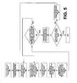
- FIG. 5is a flowchart illustrating operation of an example method for controlling transmit range in a multi-modulation communication system.
- One example approach for reducing multi-modulation transmit rangeis to vary the 802.11 receive sensitivity between ⁇ 90 dBm and ⁇ 60 dBm.
- FIG. 1shows a plot of connection rate versus path loss for various receive sensitivity settings.
- the plot in FIG. 1shows the typical effect upon data rate and range of varying the receive sensitivity of an example access point from example values of ⁇ 90 dBm to ⁇ 65 dBm in 5 dB steps.
- the example valuesare derived from the SNR requirements of the various modulation types of Table 1 and are for illustrative purpose only without being a limitation to the scope of the invention.
- FIG. 1illustrates that reducing the receive threshold preserves the higher data rates and reduces the use of lower less efficient data rates. It is appreciated that all data rates may continue to be supported and in fact may be utilized for various channel co-ordination functions. As an example of a typical 802.11 access point, the transmit power may be varied between a maximum of 20 dBm and a minimum of ⁇ 10 dBm.
- FIG. 2shows a plot of connection rate versus path loss for various transmit powers.
- the typical effect upon data rate and range of varying the transmit power of the example access point from 20 dBm to ⁇ 5 dBm in 5 dB stepsis shown.
- the example valuesmay be derived from the SNR requirements of the various modulation types of Table 1 and are for illustrative purpose only without being a limitation to the scope of the invention.
- FIG. 2shows a much less desirable limiting of range by lowering transmit power.
- the higher more efficient data ratesmay be sacrificed and the lower less efficient data rates may be preserved.
- thisis the opposite of what occurs when reducing receive threshold.
- controlling transmit power along with receiver sensitivity to limit the range of an access pointreduces transmit range and associated interference with nearby access points. This reduction in interference allows higher access point density and improves channel re-use.
- the power at which each modulation type from Table 1 above is transmittedmay be adjusted to limit transmit range while preserving the use of higher more efficient data rates.
- Many variations of actual power selection methodsare possible and useful in example implementations.
- an example methodmakes use of the differences in SNR required to successfully communicate at various modulation rates.
- Table 1in one example, it is possible to derive suitable power levels as shown in Table 2.
- Table 2may be used to specify requirements of a power reduction method which preserves the use of higher more efficient modulation rates while reducing power to limit range and to allow dense access point deployments.
- the transmittermay be set to the desired power level for the desired modulation rate.
- An example method for reducing transmitter powermay first reduce the power designated for the lowest data rate until it has been reduced by the difference in SNR between it and the second lowest data rate.
- the methodmay continue the reduction of power by reducing the power of both the second lowest and the lowest data rate until the second has been reduced by the difference in SNR between it and the third lowest data rate.
- the methodmay further continue the power reductions by reducing the power of each succeeding higher data rate until it has been reduced by the difference in SNR required for the next higher rate while simultaneously reducing power on all lesser data rates.
- Table 3The Results of this example process for an example access point is shown in Table 3.
- FIG. 3shows a plot of connection rate versus path loss for various nominal transmit powers from table 3.
- FIG. 3shows the effects of using modulation dependent transmit power control to reduce the range of an example access point. It is appreciated that by reducing the transmit powers of the lowest least efficient data rates before reducing those of higher more efficient data rates the higher more efficient data rates are preserved while limiting range to allow for dense deployments. It is also appreciated that all data rates may continue to be supported and may be used for various channel co-ordination functions.
- FIG. 4is a schematic block diagram illustrating operation of an example system 400 for controlling transmit range in a multi-modulation communication system.
- the system 400includes a signal modulator 402 , a signal transmitter 404 , an antenna 406 , a power adjuster 408 , a multi-modulation function 410 , and a transmitter controller 412 .
- the signal modulator 402receives a data signal having data formatted for transmission to a receiver (not shown).
- the signal modulator 402modulates the data signal using a selected modulation scheme and couples a modulated signal to the signal transmitter 404 for transmission to a receiver via the antenna 406 .
- the signal modulator 402may receive indication of a selected modulation scheme from the multi-modulation function 410 .
- the multi-modulation function 410may select a modulation scheme from a list of modulation schemes to enable communication of the data signal at a desired data rate.
- the data rates for each modulation schememay be configured to communicate at the data rates listed in Table 1.
- the power adjuster 408adjusts the power level of the signal transmitter 404 as described above with reference to Table 3.
- the power adjuster 408may be controlled by the transmitter controller 412 .
- the transmitter controller 412may implement hardware and software functions that carry out the progression of power level selections described above in deriving the data listed in Table 3.
- the transmitter controller 412may retrieve from data storage a receiver noise figure.
- the receiver noise figuremay be obtained from some data store or determined using any suitable method for calculating a noise figure.
- Specific noise figures for specific receiversmay be stored in a database if such knowledge is available. As described above, most present day receivers operating at normal ambient temperatures have similar noise figures.
- the receiver noise figuremay be used to determine a transmitter power that will achieve a desired SNR.
- the ‘Noise’ component in an example implementationmay be the receiver noise figure.
- the ‘Signal’ componentis a function of the transmitter power, antenna gain and path loss.
- the antenna gainmay be a known parameter available, for example, in computer memory or from a hardware and software function configured to provide the antenna gain.
- the path lossmay be simplified to represent the range or distance between transmitter and receiver. For purposes of determining a transmitter power, the path loss may represent the desired maximum range of the transmitter.
- SNR(Transmitter Power+Antenna Gain+Path Loss)/Noise Figure (Eqn. 1)
- SNR*Noise FigureTransmitter Power+Antenna Gain+Path Loss (Eqn. 2)
- Transmitter Power(SNR*Noise Figure) ⁇ (Antenna Gain+Path Loss) (Eqn. 3)
- Eqn. 3 aboveprovides a relationship that may be implemented as a computer program, for example, to determine the transmitter power that will limit the transmitter range as desired.
- the selected SNRmay be selected based on the desired data rate.
- the transmitter powermay be determined during a configuration of a particular installation of a wireless transmitter and receiver, such as a wireless access point. During such a configuration, a desired limited range may be determined according to the environment of the access point and the locations of neighboring access points.
- the transmitter controller 412may include functions for generating a table of data similar to Table 3. As the transmitter system switches to different modulation methods during operation, the table similar to Table 3 may be used to generate a new power level for the selected modulation method.
- FIG. 5is a flowchart illustrating operation of an example method 500 for controlling transmit range in a multi-modulation communication system.
- the method 500may be implemented using an example system such as the system 400 in FIG. 4 .
- a transmitter power reduction methodis initiated. Initialization may include retrieving parameters and/or querying a user for input such as a desired transmitter range limit. For example, constants such as the antenna gain and receiver noise figure may be determined or retrieved, and the path loss may be defined according to a desired transmitter range.
- minimum transmitter power levels sufficient to communicate signals to a receiver at a predetermined maximum rangeare determined for a selected group of modulation methods.
- a table similar to Table 3may be created and stored for use during operation of the multi-modulation communication system.
- a current modulation methodis identified.
- the first modulation usedis the modulation method specified to operate at the lowest data rate.
- a current modulation method transmitter poweris set to the maximum power (MAX_power) level at which the transmitter may be specified to operate.
- the current transmitter poweris reduced by one increment of the power level. In Table 3, the current transmitter power is reduced by 1 dBm each time the power level is reduced.
- the power level for each of the lower data rate modulation methodsis also reduced by the increment.
- the SNRis calculated for the current modulation method at the current transmitter power.
- the SNR difference between the minimum SNR of the current modulation method and the minimum SNR of the next lowest modulation methodis determined. In one example, the SNR difference may be obtained from a table such as Table 2.
- Decision block 516determines a difference between the current modulation method transmitter power and the next lowest data rate modulation method transmitter power and compared with the SNR difference calculated in step 514 . If the difference between transmitter power levels is the same as the SNR difference calculated at step 514 , the transmitter power at the current modulation method is set to the current transmitter power at step 518 . If the difference between transmitter power levels is not the same as the SNR difference calculated at step 514 , the method proceeds to step 508 where the transmitter power level is reduced for a next test.
- the methoddetermines if a transmitter power level has been determined for each modulation method. If the current modulation method is the modulation method having the highest data rate, the process is complete and the results are stored in a table that may be similar to Table 3. If the current modulation method is not the modulation method having the highest data rate, the modulation method with the next lowest data rate is designated to be the current modulation method at step 522 . The method then proceeds to step 506 where the current transmitter power level is set to MAX power.
- the transmitter controller 412may store a table from which a transmitter power level may be retrieved for a given modulation method to limit the transmitter range to a desired range.
- the transmitter power levelmay be modified by the power adjuster 408 (for example) as the system switches from one modulation method to another.
- a transmitter controlleris described above with reference to FIG. 4 .
- the transmitter controllermay be implemented using hardware and/or software functions.
- the functions implementing a transmitter controllermay be distributed among different functions and components.
Landscapes
- Engineering & Computer Science (AREA)
- Computer Networks & Wireless Communication (AREA)
- Signal Processing (AREA)
- Mobile Radio Communication Systems (AREA)
- Transmitters (AREA)
Abstract
Description
| TABLE 1 | ||||
| Modulation | Data Rate | Required | ||
| (Method) | (Mbps) | SNR (dB) | ||
| BPSK ½ | 6 | 8 | ||
| BPSK ¾ | 9 | 9 | ||
| QPSK ½ | 12 | 11 | ||
| QPSK ¾ | 18 | 13 | ||
| 16-QAM ½ | 24 | 16 | ||
| 16-QAM ¾ | 36 | 20 | ||
| 64-QAM ⅔ | 48 | 24 | ||
| 64-QAM ¾ | 54 | 25 | ||
| In order to simplify the discussions Modulation Methods are often described by their associated Data Rate. For example, 64-QAM ¾ modulation is described as 54 Mbps modulation. | ||||
| TABLE 2 |
| Difference in SNR Required to Maintain Communication |
| for various Modulation Rates |
| Modulation | ||||||||
| Rate | 54 | 48 | 36 | 24 | 18 | 12 | 9 | 6 |
| 54 | 0 | |||||||
| 48 | 3 | 0 | ||||||
| 36 | 5 | 4 | 0 | |||||
| 24 | 9 | 8 | 4 | 0 | ||||
| 18 | 12 | 11 | 7 | 3 | 0 | |||
| 12 | 14 | 13 | 9 | 5 | 2 | 0 | ||
| 9 | 16 | 15 | 11 | 7 | 4 | 2 | 0 | |
| 6 | 19 | 16 | 12 | 8 | 5 | 3 | 1 | 0 |
| TABLE 3 | ||||||||
| 6 | 9 | 12 | 18 | 24 | 36 | 48 | 54 | |
| Nominal | Mbps | Mbps | Mbps | Mbps | Mbps | Mbps | Mbps | Mbps |
| Power | Power | Power | Power | Power | Power | Power | Power | Power |
| dBm | dBm | dBm | dBm | dBm | dBm | dBm | dBm | dBm |
| 20 | 20 | 20 | 20 | 20 | 20 | 20 | 20 | 20 |
| 19 | 19 | 20 | 20 | 20 | 20 | 20 | 20 | 20 |
| 18 | 18 | 19 | 20 | 20 | 20 | 20 | 20 | 20 |
| 17 | 17 | 18 | 20 | 20 | 20 | 20 | 20 | 20 |
| 16 | 16 | 17 | 19 | 20 | 20 | 20 | 20 | 20 |
| 15 | 15 | 16 | 18 | 20 | 20 | 20 | 20 | 20 |
| 14 | 14 | 15 | 17 | 19 | 20 | 20 | 20 | 20 |
| 13 | 13 | 14 | 16 | 18 | 20 | 20 | 20 | 20 |
| 12 | 12 | 13 | 15 | 17 | 20 | 20 | 20 | 20 |
| 11 | 11 | 12 | 14 | 16 | 19 | 20 | 20 | 20 |
| 10 | 10 | 11 | 13 | 15 | 18 | 20 | 20 | 20 |
| 9 | 9 | 10 | 12 | 14 | 17 | 20 | 20 | 20 |
| 8 | 8 | 9 | 11 | 13 | 16 | 20 | 20 | 20 |
| 7 | 7 | 8 | 10 | 12 | 15 | 19 | 20 | 20 |
| 6 | 6 | 7 | 9 | 11 | 14 | 18 | 20 | 20 |
| 5 | 5 | 6 | 8 | 10 | 13 | 17 | 20 | 20 |
| 4 | 4 | 5 | 7 | 9 | 12 | 16 | 20 | 20 |
| 3 | 3 | 4 | 6 | 8 | 11 | 15 | 19 | 20 |
| 2 | 2 | 3 | 5 | 7 | 10 | 14 | 18 | 20 |
| 1 | 1 | 2 | 4 | 6 | 9 | 13 | 17 | 20 |
| 0 | 0 | 1 | 3 | 5 | 8 | 12 | 16 | 19 |
| −1 | −1 | 0 | 2 | 4 | 7 | 11 | 15 | 18 |
| −2 | −2 | −1 | 1 | 3 | 6 | 10 | 14 | 17 |
| −3 | −3 | −2 | 0 | 2 | 5 | 9 | 13 | 16 |
| −4 | −4 | −3 | −1 | 1 | 4 | 8 | 12 | 15 |
| −5 | −5 | −4 | −2 | 0 | 3 | 7 | 11 | 14 |
| −6 | −6 | −5 | −3 | −1 | 2 | 6 | 10 | 13 |
| −7 | −7 | −6 | −4 | −2 | 1 | 5 | 9 | 12 |
| −8 | −8 | −7 | −5 | −3 | 0 | 4 | 8 | 11 |
| −9 | −9 | −8 | −6 | −4 | −1 | 3 | 7 | 10 |
| −10 | −10 | −9 | −7 | −5 | −2 | 2 | 6 | 9 |
SNR=(Transmitter Power+Antenna Gain+Path Loss)/Noise Figure (Eqn. 1)
SNR*Noise Figure=Transmitter Power+Antenna Gain+Path Loss (Eqn. 2)
Transmitter Power=(SNR*Noise Figure)−(Antenna Gain+Path Loss) (Eqn. 3)
Eqn. 3 above provides a relationship that may be implemented as a computer program, for example, to determine the transmitter power that will limit the transmitter range as desired. The selected SNR may be selected based on the desired data rate.
Claims (8)
Priority Applications (1)
| Application Number | Priority Date | Filing Date | Title |
|---|---|---|---|
| US11/939,541US8116697B2 (en) | 2006-11-10 | 2007-11-13 | System and method for reducing multi-modulation radio transmit range |
Applications Claiming Priority (2)
| Application Number | Priority Date | Filing Date | Title |
|---|---|---|---|
| US85814206P | 2006-11-10 | 2006-11-10 | |
| US11/939,541US8116697B2 (en) | 2006-11-10 | 2007-11-13 | System and method for reducing multi-modulation radio transmit range |
Publications (2)
| Publication Number | Publication Date |
|---|---|
| US20080113634A1 US20080113634A1 (en) | 2008-05-15 |
| US8116697B2true US8116697B2 (en) | 2012-02-14 |
Family
ID=39369768
Family Applications (1)
| Application Number | Title | Priority Date | Filing Date |
|---|---|---|---|
| US11/939,541Expired - Fee RelatedUS8116697B2 (en) | 2006-11-10 | 2007-11-13 | System and method for reducing multi-modulation radio transmit range |
Country Status (1)
| Country | Link |
|---|---|
| US (1) | US8116697B2 (en) |
Cited By (3)
| Publication number | Priority date | Publication date | Assignee | Title |
|---|---|---|---|---|
| US20120105154A1 (en)* | 2006-11-09 | 2012-05-03 | Parkervision, Inc. | Switching Power Supply |
| US9413233B2 (en) | 2005-10-24 | 2016-08-09 | Parkervision, Inc. | Switching power supply with dynamically programmed threshold voltage |
| US11647497B2 (en)* | 2018-03-28 | 2023-05-09 | Telefonaktiebolaget Lm Ericsson (Publ) | Uplink scheduling based on upper and lower SNR targets |
Families Citing this family (30)
| Publication number | Priority date | Publication date | Assignee | Title |
|---|---|---|---|---|
| US8081712B2 (en)* | 2007-02-02 | 2011-12-20 | Interdigital Technology Corporation | Method and apparatus for mapping of absolute power grant values in wireless communications |
| RU2480933C2 (en) | 2008-08-20 | 2013-04-27 | Квэлкомм Инкорпорейтед | Muros modulation using linear baseband combinations with linear gaussian pulse shaping for two users on one timeslot used by non-darp and darp remote stations |
| WO2010021635A1 (en)* | 2008-08-20 | 2010-02-25 | Qualcomm Incorporated | Power control method for a geran system to increase geran network capacity |
| CN102131279B (en)* | 2010-11-26 | 2013-08-28 | 华为技术有限公司 | Method and device for adjusting transmission power |
| US10368318B2 (en)* | 2010-12-30 | 2019-07-30 | Telefonaktiebolaget Lm Ericsson (Publ) | Wireless operation in very high density environments |
| JP5594310B2 (en)* | 2012-03-28 | 2014-09-24 | 株式会社デンソー | Vehicle communication device |
| US10231206B2 (en) | 2013-03-15 | 2019-03-12 | DGS Global Systems, Inc. | Systems, methods, and devices for electronic spectrum management for identifying signal-emitting devices |
| US10257728B2 (en) | 2013-03-15 | 2019-04-09 | DGS Global Systems, Inc. | Systems, methods, and devices for electronic spectrum management |
| US10271233B2 (en) | 2013-03-15 | 2019-04-23 | DGS Global Systems, Inc. | Systems, methods, and devices for automatic signal detection with temporal feature extraction within a spectrum |
| US9078162B2 (en) | 2013-03-15 | 2015-07-07 | DGS Global Systems, Inc. | Systems, methods, and devices for electronic spectrum management |
| US10257729B2 (en) | 2013-03-15 | 2019-04-09 | DGS Global Systems, Inc. | Systems, methods, and devices having databases for electronic spectrum management |
| US11646918B2 (en) | 2013-03-15 | 2023-05-09 | Digital Global Systems, Inc. | Systems, methods, and devices for electronic spectrum management for identifying open space |
| US8750156B1 (en) | 2013-03-15 | 2014-06-10 | DGS Global Systems, Inc. | Systems, methods, and devices for electronic spectrum management for identifying open space |
| US12256233B2 (en) | 2013-03-15 | 2025-03-18 | Digital Global Systems, Inc. | Systems and methods for automated financial settlements for dynamic spectrum sharing |
| US10237770B2 (en) | 2013-03-15 | 2019-03-19 | DGS Global Systems, Inc. | Systems, methods, and devices having databases and automated reports for electronic spectrum management |
| US10299149B2 (en) | 2013-03-15 | 2019-05-21 | DGS Global Systems, Inc. | Systems, methods, and devices for electronic spectrum management |
| US12356206B2 (en) | 2013-03-15 | 2025-07-08 | Digital Global Systems, Inc. | Systems and methods for automated financial settlements for dynamic spectrum sharing |
| US10244504B2 (en) | 2013-03-15 | 2019-03-26 | DGS Global Systems, Inc. | Systems, methods, and devices for geolocation with deployable large scale arrays |
| US10257727B2 (en)* | 2013-03-15 | 2019-04-09 | DGS Global Systems, Inc. | Systems methods, and devices having databases and automated reports for electronic spectrum management |
| US10219163B2 (en) | 2013-03-15 | 2019-02-26 | DGS Global Systems, Inc. | Systems, methods, and devices for electronic spectrum management |
| US10038569B2 (en)* | 2016-03-29 | 2018-07-31 | Intel IP Corporation | Self-adapting baud rate |
| WO2018031951A1 (en)* | 2016-08-11 | 2018-02-15 | Hopzero, Inc. | Method and system for limiting the range of data transmissions |
| US10459020B2 (en) | 2017-01-23 | 2019-10-29 | DGS Global Systems, Inc. | Systems, methods, and devices for automatic signal detection based on power distribution by frequency over time within a spectrum |
| US10498951B2 (en) | 2017-01-23 | 2019-12-03 | Digital Global Systems, Inc. | Systems, methods, and devices for unmanned vehicle detection |
| US10700794B2 (en) | 2017-01-23 | 2020-06-30 | Digital Global Systems, Inc. | Systems, methods, and devices for automatic signal detection based on power distribution by frequency over time within an electromagnetic spectrum |
| US12183213B1 (en) | 2017-01-23 | 2024-12-31 | Digital Global Systems, Inc. | Unmanned vehicle recognition and threat management |
| US12205477B2 (en) | 2017-01-23 | 2025-01-21 | Digital Global Systems, Inc. | Unmanned vehicle recognition and threat management |
| US10529241B2 (en) | 2017-01-23 | 2020-01-07 | Digital Global Systems, Inc. | Unmanned vehicle recognition and threat management |
| US10943461B2 (en) | 2018-08-24 | 2021-03-09 | Digital Global Systems, Inc. | Systems, methods, and devices for automatic signal detection based on power distribution by frequency over time |
| US11765668B2 (en)* | 2018-09-28 | 2023-09-19 | Apple Inc. | LTE NR power control for EN-DC |
Citations (2)
| Publication number | Priority date | Publication date | Assignee | Title |
|---|---|---|---|---|
| US20040240424A1 (en)* | 2003-03-06 | 2004-12-02 | Mo-Han Fong | Reverse link enhancement for CDMA 2000 release D |
| US20050025254A1 (en)* | 2003-07-31 | 2005-02-03 | Awad Yassin Aden | Adaptive modulation and coding |
- 2007
- 2007-11-13USUS11/939,541patent/US8116697B2/ennot_activeExpired - Fee Related
Patent Citations (2)
| Publication number | Priority date | Publication date | Assignee | Title |
|---|---|---|---|---|
| US20040240424A1 (en)* | 2003-03-06 | 2004-12-02 | Mo-Han Fong | Reverse link enhancement for CDMA 2000 release D |
| US20050025254A1 (en)* | 2003-07-31 | 2005-02-03 | Awad Yassin Aden | Adaptive modulation and coding |
Cited By (5)
| Publication number | Priority date | Publication date | Assignee | Title |
|---|---|---|---|---|
| US9413233B2 (en) | 2005-10-24 | 2016-08-09 | Parkervision, Inc. | Switching power supply with dynamically programmed threshold voltage |
| US20120105154A1 (en)* | 2006-11-09 | 2012-05-03 | Parkervision, Inc. | Switching Power Supply |
| US8285229B2 (en)* | 2006-11-09 | 2012-10-09 | Parkervision, Inc. | Switching power supply |
| US8498593B2 (en) | 2006-11-09 | 2013-07-30 | Parkervision, Inc. | Switching power supply |
| US11647497B2 (en)* | 2018-03-28 | 2023-05-09 | Telefonaktiebolaget Lm Ericsson (Publ) | Uplink scheduling based on upper and lower SNR targets |
Also Published As
| Publication number | Publication date |
|---|---|
| US20080113634A1 (en) | 2008-05-15 |
Similar Documents
| Publication | Publication Date | Title |
|---|---|---|
| US8116697B2 (en) | System and method for reducing multi-modulation radio transmit range | |
| US9084205B2 (en) | Uplink power control scheme for a wireless communication system | |
| RU2369965C2 (en) | Information on noise from multiple sectors for power control | |
| TWI475904B (en) | Interference control in a wireless communication system | |
| KR100949018B1 (en) | Power control and quality of serviceqos implementation in a communication system | |
| JP4440784B2 (en) | Power control for mobile station in CDMA-TDD system | |
| US8306567B2 (en) | Fast adaptive power control for a variable multirate communications system | |
| US7047032B2 (en) | Power controllable wireless mobile communications system of adaptive modulation and coding scheme and method therefor | |
| JP4270714B2 (en) | Mobile station and mobile radio communication system | |
| CN101627553B (en) | Power control messaging scheme | |
| KR20120088867A (en) | Method and apparatus for adjustments for delta-based power control in wireless communication systems | |
| CN101171811B (en) | Interference Control Method and Device in Wireless Communication System | |
| KR20190035830A (en) | Wireless communication system and wireless communication method | |
| US20030156554A1 (en) | Method for regulating transmission power in a radiocommunications system | |
| US10420034B1 (en) | Systems and methods for adaptively controlling uplink communications parameters by an access point | |
| CN109462862A (en) | One kind is based on probability can close property interference bypassing method | |
| JP2004072663A (en) | Antenna control device | |
| CN101494894B (en) | Backward power control method and control device | |
| US11032826B2 (en) | Radio spectrum sharing leveraging link adaptation in primary network | |
| KR20000056456A (en) | Outer loop power controlling method | |
| Koetz et al. | Efficient adaptation of modulation and coding schemes in high quality home networks |
Legal Events
| Date | Code | Title | Description |
|---|---|---|---|
| AS | Assignment | Owner name:XIRRUS, INC., CALIFORNIA Free format text:ASSIGNMENT OF ASSIGNORS INTEREST;ASSIGNORS:GATES, DIRK ION;MATTHEWS, KIRK;SAUTER, KURT;REEL/FRAME:020426/0774 Effective date:20080115 | |
| ZAAA | Notice of allowance and fees due | Free format text:ORIGINAL CODE: NOA | |
| ZAAB | Notice of allowance mailed | Free format text:ORIGINAL CODE: MN/=. | |
| STCF | Information on status: patent grant | Free format text:PATENTED CASE | |
| AS | Assignment | Owner name:SILICON VALLEY BANK, CALIFORNIA Free format text:SECURITY AGREEMENT;ASSIGNOR:XIRRUS, INC.;REEL/FRAME:028307/0162 Effective date:20120530 | |
| AS | Assignment | Owner name:CARR & FERRELL, LLP, CALIFORNIA Free format text:SECURITY AGREEMENT;ASSIGNOR:XIRRUS, INC.;REEL/FRAME:029923/0752 Effective date:20130208 | |
| AS | Assignment | Owner name:TRIPLEPOINT CAPITAL LLC, CALIFORNIA Free format text:SECURITY AGREEMENT;ASSIGNOR:XIRRUS, INC.;REEL/FRAME:031867/0745 Effective date:20131220 | |
| AS | Assignment | Owner name:CARR & FERRELL LLP, CALIFORNIA Free format text:SECURITY AGREEMENT;ASSIGNOR:XIRRUS, INC.;REEL/FRAME:032380/0252 Effective date:20131119 | |
| AS | Assignment | Owner name:TRIPLEPOINT VENTURE GROWTH BDC CORP., CALIFORNIA Free format text:ASSIGNMENT OF SECURITY AGREEMENT (REEL 031867, FRAME 0745);ASSIGNOR:TRIPLEPOINT CAPITAL LLC;REEL/FRAME:032410/0338 Effective date:20140305 | |
| AS | Assignment | Owner name:XIRRUS, INC., CALIFORNIA Free format text:RELEASE BY SECURED PARTY;ASSIGNOR:CARR & FERRELL LLP;REEL/FRAME:032794/0290 Effective date:20140422 Owner name:XIRRUS, INC., CALIFORNIA Free format text:RELEASE BY SECURED PARTY;ASSIGNOR:CARR & FERRELL LLP;REEL/FRAME:032794/0265 Effective date:20140422 | |
| REMI | Maintenance fee reminder mailed | ||
| FPAY | Fee payment | Year of fee payment:4 | |
| SULP | Surcharge for late payment | ||
| AS | Assignment | Owner name:XIRRUS, INC., CALIFORNIA Free format text:RELEASE OF INTELLECTUAL PROPERTY SECURITY AGREEMENT RECORDED AT REEL 028307/FRAME 0162;ASSIGNOR:SILICON VALLEY BANK;REEL/FRAME:042388/0296 Effective date:20170421 Owner name:XIRRUS, INC., CALIFORNIA Free format text:RELEASE OF SECURITY INTEREST RECORDED AT REEL 031867/FRAME 0745;ASSIGNOR:TRIPLEPOINT VENTURE GROWTH BDC CORP., AS ASSIGNEE OF TRIPLEPOINT CAPITAL LLC;REEL/FRAME:042388/0753 Effective date:20170424 | |
| AS | Assignment | Owner name:XIRRUS LLC, CALIFORNIA Free format text:CONVERSION TO LIMITED LIABILITY COMPANY;ASSIGNOR:XIRRUS, INC.;REEL/FRAME:047100/0874 Effective date:20170601 | |
| AS | Assignment | Owner name:RIVERBED TECHNOLOGY, INC., CALIFORNIA Free format text:ASSIGNMENT OF ASSIGNORS INTEREST;ASSIGNOR:XIRRUS LLC;REEL/FRAME:047706/0936 Effective date:20180814 | |
| AS | Assignment | Owner name:MORGAN STANLEY SENIOR FUNDING, INC., AS COLLATERAL Free format text:PATENT SECURITY AGREEMENT;ASSIGNOR:RIVERBED TECHNOLOGY, INC.;REEL/FRAME:049720/0808 Effective date:20190703 Owner name:MORGAN STANLEY SENIOR FUNDING, INC., AS COLLATERAL AGENT, MARYLAND Free format text:PATENT SECURITY AGREEMENT;ASSIGNOR:RIVERBED TECHNOLOGY, INC.;REEL/FRAME:049720/0808 Effective date:20190703 | |
| AS | Assignment | Owner name:RIVERBED TECHNOLOGY, INC., CALIFORNIA Free format text:RELEASE OF SECURITY INTEREST IN CERTAIN PATENTS;ASSIGNOR:MORGAN STANLEY SENIOR FUNDING, INC.;REEL/FRAME:050016/0600 Effective date:20190807 | |
| MAFP | Maintenance fee payment | Free format text:PAYMENT OF MAINTENANCE FEE, 8TH YEAR, LARGE ENTITY (ORIGINAL EVENT CODE: M1552); ENTITY STATUS OF PATENT OWNER: LARGE ENTITY Year of fee payment:8 | |
| FEPP | Fee payment procedure | Free format text:ENTITY STATUS SET TO UNDISCOUNTED (ORIGINAL EVENT CODE: BIG.); ENTITY STATUS OF PATENT OWNER: LARGE ENTITY | |
| AS | Assignment | Owner name:CAMBIUM NETWORKS, LTD., UNITED KINGDOM Free format text:ASSIGNMENT OF ASSIGNORS INTEREST;ASSIGNOR:RIVERBED TECHNOLOGY, INC.;REEL/FRAME:051894/0194 Effective date:20190805 | |
| FEPP | Fee payment procedure | Free format text:MAINTENANCE FEE REMINDER MAILED (ORIGINAL EVENT CODE: REM.); ENTITY STATUS OF PATENT OWNER: LARGE ENTITY | |
| LAPS | Lapse for failure to pay maintenance fees | Free format text:PATENT EXPIRED FOR FAILURE TO PAY MAINTENANCE FEES (ORIGINAL EVENT CODE: EXP.); ENTITY STATUS OF PATENT OWNER: LARGE ENTITY | |
| STCH | Information on status: patent discontinuation | Free format text:PATENT EXPIRED DUE TO NONPAYMENT OF MAINTENANCE FEES UNDER 37 CFR 1.362 | |
| FP | Lapsed due to failure to pay maintenance fee | Effective date:20240214 |