US8116497B2 - Portable speaker system for outdoor umbrella - Google Patents
Portable speaker system for outdoor umbrellaDownload PDFInfo
- Publication number
- US8116497B2 US8116497B2US11/827,732US82773207AUS8116497B2US 8116497 B2US8116497 B2US 8116497B2US 82773207 AUS82773207 AUS 82773207AUS 8116497 B2US8116497 B2US 8116497B2
- Authority
- US
- United States
- Prior art keywords
- housing body
- housing
- portable
- locker
- outdoor umbrella
- Prior art date
- Legal status (The legal status is an assumption and is not a legal conclusion. Google has not performed a legal analysis and makes no representation as to the accuracy of the status listed.)
- Expired - Fee Related, expires
Links
- 230000005236sound signalEffects0.000claimsabstractdescription20
- 230000008878couplingEffects0.000claimsabstractdescription14
- 238000010168coupling processMethods0.000claimsabstractdescription14
- 238000005859coupling reactionMethods0.000claimsabstractdescription14
- 230000014759maintenance of locationEffects0.000claimsdescription21
- 230000006835compressionEffects0.000claimsdescription7
- 238000007906compressionMethods0.000claimsdescription7
- 235000012489doughnutsNutrition0.000claimsdescription3
- 238000005286illuminationMethods0.000description2
- 230000009471actionEffects0.000description1
- 230000008859changeEffects0.000description1
- LTMHDMANZUZIPE-PUGKRICDSA-NdigoxinChemical compoundC1[C@H](O)[C@H](O)[C@@H](C)O[C@H]1O[C@@H]1[C@@H](C)O[C@@H](O[C@@H]2[C@H](O[C@@H](O[C@@H]3C[C@@H]4[C@]([C@@H]5[C@H]([C@]6(CC[C@@H]([C@@]6(C)[C@H](O)C5)C=5COC(=O)C=5)O)CC4)(C)CC3)C[C@@H]2O)C)C[C@@H]1OLTMHDMANZUZIPE-PUGKRICDSA-N0.000description1
- 230000002452interceptive effectEffects0.000description1
- 230000007257malfunctionEffects0.000description1
- 238000004519manufacturing processMethods0.000description1
- 238000000034methodMethods0.000description1
- 238000012986modificationMethods0.000description1
- 230000004048modificationEffects0.000description1
- 230000036651moodEffects0.000description1
- 230000008569processEffects0.000description1
Images


Classifications
- A—HUMAN NECESSITIES
- A45—HAND OR TRAVELLING ARTICLES
- A45B—WALKING STICKS; UMBRELLAS; LADIES' OR LIKE FANS
- A45B3/00—Sticks combined with other objects
- A—HUMAN NECESSITIES
- A45—HAND OR TRAVELLING ARTICLES
- A45B—WALKING STICKS; UMBRELLAS; LADIES' OR LIKE FANS
- A45B23/00—Other umbrellas
- A45B2023/0031—Cantilever umbrellas or sunshades with a support arm
- A45B2023/0068—Cantilever umbrellas or sunshades with a support arm the support arm being foldable
Definitions
- the present inventionrelates to an outdoor umbrella, and more particularly to a portable speaker system which is adapted to detachably mount to a conventional outdoor umbrella so as to provide an add-on function for the conventional outdoor umbrella without altering its original structure.
- Outdoors umbrellasare set up in many places such as in beach areas, in patio areas, in campsites or in domestic gardens etc. They are usually used for shading sunlight in the daytime.
- a conventional outdoors umbrellausually comprises an umbrella base, a supporting stem upwardly extended therefrom, a foldable awning frame which comprises a plurality of awning supporting arms radically and outwardly extended from an upper end portion of the supporting stem, and a fabric-made awning securely and foldably mounted on the awning supporting arms.
- the outdoors umbrellasare designed for use in outdoors, existence of an electrical power source cannot be guaranteed. Even through there are electrical sources exist, a tedious connection between the audio system and the electrical source is unavoidable in that long wires have to be used.
- the audio systemsmay be compatible with portable dynamos, however, bring a bulky dynamo with the outdoor umbrella is not really a wise decision. Once the electrical connection the audio system is broken, the user is unable to replace the audio system. In other words, once the audio system is malfunction, the mood of all the participants may be ruined.
- a main object of the present inventionis to provide a portable speaker system for an outdoor umbrella, wherein the portable speaker system is adapted to detachably mount to a conventional outdoor umbrella so as to provide an add-on function for the conventional outdoor umbrella without altering its original structure.
- Another object of the present inventionis to provide a portable speaker system for an outdoor umbrella, wherein no electric wire is required to electrically connect the audio system with the outdoor umbrella.
- the portable speaker systemprovides an independent power supply such that the audio system does not require any power supply from the outdoor umbrella.
- Another object of the present inventionis to provide a portable speaker system for an outdoor umbrella, wherein the audio system is adapted to detachably mount to any type of outdoor umbrella having an elongated shaft. Therefore, the user is able to mount the portable speaker system from one outdoor umbrella to another outdoor umbrella easily.
- Another object of the present inventionis to provide a portable speaker system for an outdoor umbrella, wherein the portable speaker system does not significantly alter the original structure of the outdoors umbrella, so as to minimize the manufacturing and marketing costs of the portable speaker system incorporating with the outdoor umbrella.
- Another object of the present inventionis to provide a portable speaker system for an outdoor umbrella, wherein no complicated mechanical and electrical processes are involved in installing and mounting the portable speaker system on the outdoor umbrella.
- Another object of the present inventionis to provide a portable speaker system for an outdoor umbrella, wherein the portable speaker system further provides an added lighting function for providing illumination.
- the present inventionprovides a portable speaker system for an outdoor umbrella having a shaft, comprising:
- a portable housingwhich comprises a first housing body and a second housing body defining a mounting slot when the first and second housing bodies are coupled with each other, wherein the mounting slot has a size for the shaft of the outdoor umbrella fitting therewithin;
- a detachable lockercomprising a first locker provided at the first housing body and a second locker which is provided at the second housing body and is releasably locked with the first locker so as to detachably lock up the second housing body with the first housing body;
- an audio devicewhich comprises a speaker supported in the first housing body and an audio input operatively coupling with the speaker such that when the audio input sends an audio signal to the speaker, the speaker is adapted for producing audio sound as an additional function for the outdoor umbrella.
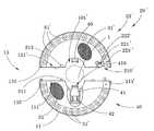
- FIG. 1is a top perspective view of a portable speaker system for an outdoor umbrella according to a preferred embodiment of the present invention.
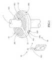
- FIG. 2is a partially schematic view of the portable speaker system according to the above preferred embodiment of the present invention.
- FIG. 3is a bottom view of the portable speaker system according to the above preferred embodiment of the present invention, illustrating the first and second housing bodies being pivotally coupled with each other via a pivot hinge.
- FIG. 4is a sectional view of the adjustable retainer according to the above preferred embodiment of the present invention.
- FIG. 5illustrates an alternative mode of the pivot hinge according to the above preferred embodiment of the present invention, illustrating the first and second housing bodies being detached with each other via a pivot hinge.
- FIG. 6illustrates an alternative mode of the adjustable retainer according to the above preferred embodiment of the present invention.
- FIG. 7illustrates the portable speaker system of the present invention being mounted to the supporting shaft of the outdoor umbrella.
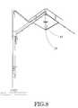
- FIG. 8illustrates the portable speaker system of the present invention being mounted to the upper portion of the awning shaft of the outdoor umbrella.
- FIG. 9illustrates the portable speaker system of the present invention being mounted to the lower portion of the supporting shaft of the outdoor umbrella.
- FIGS. 1 and 2 of the drawingsa portable speaker system for an outdoor umbrella is illustrated, wherein the portable speaker system is adapted to detachably mount to the shaft 1 of the outdoor umbrella.
- the portable speaker system of the present inventionis detachably mounted to the supporting shaft 1 A of the outdoor umbrella.
- the portable speaker system of the present inventionis detachably mounted to the upper and lower portions of the awning shaft 1 B of the outdoor umbrella.
- the portable speaker systemcomprises a portable housing 10 , a detachable locker 20 and an audio device 30 .
- the portable housing 10comprises a first housing body 11 and a second housing body 12 defining a mounting slot 101 when the first and second housing bodies 11 , 12 are coupled with each other, wherein the mounting slot 101 has a size for the shaft 1 of the outdoor umbrella fitting therewithin.
- the detachable locker 20comprises a first locker 21 provided at the first housing body 11 and a second locker 22 which is provided at the second housing body 12 and is releasably locked with the first locker 21 so as to detachably lock up the second housing body 11 with the first housing body 12 .
- the audio device 30comprises two or more speakers 31 supported in the first and second housing bodies 11 , 12 of the portable housing 10 respectively and an audio input 32 operatively coupling with the speakers 31 such that when the audio input 32 sends an audio signal to the speakers 31 , the speakers 31 are adapted for producing audio sound as an additional function for the outdoor umbrella.
- the first and second housing bodies 11 , 12are two identical half circular bodies pivotally coupling with each other via a pivot hinge 13 , wherein each of the first and second housing bodies 11 , 12 has two biasing surfaces 111 , 121 arranged when the biasing surfaces 111 of the first housing body 11 engage with the biasing surfaces 121 of the second housing body 12 respectively, the portable housing 10 is formed to have a donut shape and to define the mounting slot 101 at a center of the portable housing 10 .
- the portable speaker systemfurther comprises a lighting device 50 for providing illumination under the portable housing 10 .
- the lighting device 50comprises a plurality of illuminators 51 spacedly supported in the outer circumferential portion of the first and second housing bodies 11 , 12 and electrically coupling with the audio device 30 ′. Accordingly, each of the illuminators 51 is a LED having a head portion protruded from the bottom sides of the first and second housing bodies 11 , 12 and a tail portion electrically connecting to the audio device 30 .
- the first locker 21comprises a first locking latch 211 outwardly protruded from one of the biasing surfaces 111 of the first housing body 11 .
- the second locker 22comprises a second locking latch 221 movably supported in the second housing body 12 to align with a locking hole 210 on the respective biasing surface 121 of the second housing body 12 , wherein when the first locking latch 211 is engaged with the second is locking latch 221 through the locking hole 210 , the second housing body 12 is locked up with the first housing body 11 .
- the second locker 22further comprises a resilient element 222 supported in the second housing body 12 for applying an urging force against the second locking latch 221 so as to normally retain the second locking latch 221 being locked up with the first locking latch 211 , and a lock actuator 223 coupling with the second locking latch 221 and actuating the second locking latch 221 to disengage with the first locking latch 211 .
- the resilient element 222is a compression spring having two ends coupling with an inner wall of the second housing body 12 and the second locking latch 221 to apply the urging force against the second locking latch 221 .
- the lock actuator 223is coupled with the second locking latch 221 such that when the lock actuator 223 is actuated, the second locking latch 221 is driven to move to disengage with the first locking latch 221 so as to unlock the second housing body 12 from the first housing body 11 . Once the lock actuator 223 is released from its actuated position, the resilient element 222 drives the second locking latch 221 backs to its original position.
- the portable housing 10has an audio outlet formed at a bottom side of each of the first and second housing bodies 11 , 12 , wherein the speakers 31 are aligned with the audio opening for outputting the audio sound through the audio outlet.
- the audio input 32comprises an auxiliary input 321 provided on the portable housing for communicatively connecting a portable music player to receive the audio signal therefrom, such that the audio signal is transmitted to the speakers 31 for music broadcasting.
- the auxiliary input 321is provided on the outer surface of the first housing body 11 for the user to connect the portable music player to the speakers 31 .
- the audio input 32further a wireless receiver 323 supported in the portable housing 10 to electrically connect with the speakers 31 and a wireless transmitter 324 which is wirelessly linked with the wireless receiver 323 and is adapted for connecting with the portable music player to wirelessly sending the audio signal from the portable music player to the speakers 31 for music broadcasting.
- the wireless receiver 323is a FM receiver and the wireless transmitter 324 is a FM transmitter such that the wireless receiver 323 and the wireless transmitter 324 form a wireless link to wirelessly send the audio signal from the portable music player to the speakers 31 . Therefore, when the wireless transmitter 324 is tuned automatically or manually to match the radio frequency of the wireless receiver 323 , the audio device 30 is wirelessly connected with the portable music player.
- the portable housing 10further comprises a device holder 14 provided at the first housing body 11 for detachably holding the portable music player in position, wherein the device holder 14 comprises a plurality of holder arms 141 spacedly extended from a top side of the first housing body 11 to define a holding compartment for securely receiving the portable music player therein.
- the audio device 30further comprises a control panel 33 which is provided at the portable housing 10 , comprising a control circuitry 331 operatively connecting to the speakers 31 to selectively operate and control the speaker and a display screen 332 electrically connected to the control circuitry 331 for displaying an operation status thereof.
- the control circuitry 331is also operatively connected to the wireless receiver 323 to operate and control the wireless receiver 323 . Accordingly, a remote controller can be incorporated to remote control the audio device 30 .
- the control panel 33further comprises a radio broadcasting circuit 333 for receiving radio wave as the audio signal, such that the control panel 33 transmits the audio signal to the speakers 31 for radio broadcasting.
- a radio broadcasting circuit 333for receiving radio wave as the audio signal, such that the control panel 33 transmits the audio signal to the speakers 31 for radio broadcasting.
- the useris able to listen to the music from his or her portable music player or to the radio through the portable speaker system of the present invention.
- the audio device 30further comprises a power supply 35 supported by the portable housing 10 to electrically connect with the speakers 31 and the control panel 33 .
- the power supply 35comprises a solar energy collector 351 for collecting solar energy and a rechargeable battery 352 supported in one of the first and second housing bodies 11 , 12 for storing electrical energy converted from the solar energy, such that the audio device 30 does not require any electrical power from the outdoor umbrella.
- the power supply 35can be electrically connected to the power source of the outdoor umbrella, especially the outdoor umbrella incorporating with a solar energy.
- the solar energy collector 351comprises a plurality of solar collecting panels provided on a top side of the portable housing 10 for solar energy collection. It is worth to mention that the user is able to charge the rechargeable battery 352 by facing the solar energy collector 351 towards the sunlight such that the portable housing 10 is adapted to be mounted at the shaft 1 of the outdoor umbrella as an add-on speaker without any electrical connection to the outdoor umbrella.
- the speakers 31are supported in the first and second housing bodies 11 , 12 respectively, wherein an electric cable 311 are extended between the two corresponding biasing surfaces 111 , 121 of the first and second housing bodies 11 , 12 to electrically connect the speakers 31 with each other. Accordingly, the electric cable 311 not only electrically connects the speakers 31 with each other but also limits a pivot angle between the first and second housing bodies 11 , 12 .
- the portable speaker systemfurther comprises an adjustable retainer 40 for adjusting the size of the mounting slot 101 for the shaft 1 of the outdoor umbrella.
- the adjustable retainer 40comprises a retention arm 41 having a pusher surface 410 facing towards the mounting slot 101 and a control portion 411 rotatably coupling with the second housing body 12 such that when the control portion 411 is driven to rotate, the pusher surface 410 is adjustably move to adjust the size of the mounting slot 101 .
- the control portion 411 of the retention arm 41has an outer threaded portion engaging with an inner threaded portion of a sidewall of the second housing body 12 .
- the adjustable retainer 40further comprises a compression spring 42 coaxially mounted at the retention arm 41 for applying an urging force against the retention arm 41 to push the pusher surface 410 away from the mounting slot 101 .
- a compression spring 42coaxially mounted at the retention arm 41 for applying an urging force against the retention arm 41 to push the pusher surface 410 away from the mounting slot 101 .
- FIG. 5illustrates an alternative mode of the pivot hinge 13 ′.
- the first housing body 11 ′is pivotally coupled with the second housing body 12 ′ via a pivot hinge 13 ′.
- the pivot hinge 13 ′comprises a pivot shaft 131 ′ provided at the first housing body 11 ′ and a detachable coupler 132 ′ which is extended from the second housing body 11 ′ and is detachably coupled with the pivot shaft 131 ′ to pivotally connect the second housing body 12 ′ with the first housing body 11 ′. Therefore, once the detachable coupler 132 ′ couples with the pivot shaft 131 ′, the first and second housing bodies 11 ′, 12 are pivotally moved with respect to the pivot shaft 131 ′.
- the pivot hinge 13 ′not only pivotally connects the first and second housing bodies 11 ′, 12 ′ with each other but also detachably mounts the first and second housing bodies 11 ′, 12 ′ with each other.
- the adjustable retainer 40 ′comprises a retention arm 41 ′, having a pusher surface 410 ′ facing towards the mounting slot 101 ′, slidably mounted the first housing body 11 ′ and an adjustable locker 42 ′ controllably driving the retention arm 41 ′ at a position that when the retention arm 41 ′ is driven towards mounting slot 101 ′, the pusher surface 410 ′ is arranged for biasing against an outer surface of the shaft 1 of the outdoor umbrella until the shaft 1 thereof being fitted at the mounting slot 101 ′ so as to substantially mount the portable housing 10 ′ at the outdoor umbrella.
- the adjustable retainer 42 ′comprises a compression spring supported in the first housing body 11 ′ for applying a pushing force against the retention arm 41 ′ so as to normally push the pusher surface 410 ′ towards the mounting slot 101 ′.
- an electric plug 311 ′is extended from the corresponding biasing surface 111 ′ of the first housing body 11 ′ and is electrically coupled with the speaker 31 ′ thereat.
- An electric socket 312 ′is extended from the corresponding biasing surface 121 ′ of the second housing body 12 ′ and is electrically coupled with the speaker 31 ′ thereat, wherein the electric plug 311 ′ is electrically coupled to the electric socket 312 ′ when the first and second housing bodies 11 ′, 12 ′ are coupled with each other via the pivot hinge 13 ′.
Landscapes
- Structure Of Receivers (AREA)
- Holders For Apparel And Elements Relating To Apparel (AREA)
Abstract
Description
Claims (3)
Priority Applications (1)
| Application Number | Priority Date | Filing Date | Title |
|---|---|---|---|
| US11/827,732US8116497B2 (en) | 2007-07-13 | 2007-07-13 | Portable speaker system for outdoor umbrella |
Applications Claiming Priority (1)
| Application Number | Priority Date | Filing Date | Title |
|---|---|---|---|
| US11/827,732US8116497B2 (en) | 2007-07-13 | 2007-07-13 | Portable speaker system for outdoor umbrella |
Publications (2)
| Publication Number | Publication Date |
|---|---|
| US20090014041A1 US20090014041A1 (en) | 2009-01-15 |
| US8116497B2true US8116497B2 (en) | 2012-02-14 |
Family
ID=40252100
Family Applications (1)
| Application Number | Title | Priority Date | Filing Date |
|---|---|---|---|
| US11/827,732Expired - Fee RelatedUS8116497B2 (en) | 2007-07-13 | 2007-07-13 | Portable speaker system for outdoor umbrella |
Country Status (1)
| Country | Link |
|---|---|
| US (1) | US8116497B2 (en) |
Cited By (15)
| Publication number | Priority date | Publication date | Assignee | Title |
|---|---|---|---|---|
| US20120067252A1 (en)* | 2010-09-21 | 2012-03-22 | Timothy Mallon | Extendable Table for Use with an Outdoor Umbrella |
| US9030829B2 (en) | 2012-10-22 | 2015-05-12 | Oliver Joen-An Ma | Modular accessory |
| US9949540B2 (en) | 2016-05-09 | 2018-04-24 | Shadecraft, Inc. | Automated intelligent shading objects and computer-readable instructions for interfacing with, communicating with and controlling a shading object |
| US10078856B2 (en) | 2016-05-09 | 2018-09-18 | Shadecraft, Inc. | Mobile computing device control of shading object, intelligent umbrella and intelligent shading charging system |
| US10159316B2 (en) | 2016-05-09 | 2018-12-25 | Shadecraft, Inc. | Intelligent shading charging systems |
| US10250817B2 (en) | 2016-05-09 | 2019-04-02 | Armen Sevada Gharabegian | Shading object, intelligent umbrella and intelligent shading charging system integrated camera and method of operation |
| US10327521B2 (en) | 2015-05-22 | 2019-06-25 | Armen Sevada Gharabegian | Intelligent shading objects |
| US10455395B2 (en) | 2016-05-09 | 2019-10-22 | Armen Sevada Gharabegian | Shading object, intelligent umbrella and intelligent shading charging security system and method of operation |
| USD869718S1 (en) | 2018-02-20 | 2019-12-10 | ZHUN-AN Ma | Umbrella attached light |
| US20200060397A1 (en)* | 2018-08-21 | 2020-02-27 | Shadecraft, Inc. | Automation attachment including environmental, motion or directional sensor assemblies utilized with existing parasols or umbrellas |
| US10912357B2 (en) | 2016-05-09 | 2021-02-09 | Shadecraft, LLC | Remote control of shading object and/or intelligent umbrella |
| US11181256B2 (en) | 2018-02-20 | 2021-11-23 | ZHUN-AN Ma | Stand for portable accessory |
| US11578860B2 (en) | 2018-02-20 | 2023-02-14 | ZHUN-AN Ma | Stand for portable accessory |
| US11856347B1 (en) | 2020-01-16 | 2023-12-26 | David M. Roberts | Speaker stand |
| US20240213651A1 (en)* | 2022-12-26 | 2024-06-27 | Verizon Patent And Licensing Inc. | Mounting device |
Families Citing this family (25)
| Publication number | Priority date | Publication date | Assignee | Title |
|---|---|---|---|---|
| US8444104B2 (en)* | 2007-11-14 | 2013-05-21 | Oliver Joen-An Ma | Secure mechanism of portable accessory device for outdoor umbrella |
| US7695153B2 (en)* | 2008-02-05 | 2010-04-13 | Sam Tsai | Umbrella light with audio module |
| US20100202627A1 (en)* | 2009-01-15 | 2010-08-12 | Randolph Gray | Docking System Employing a Solar Energy Charging System |
| ITTE20090001A1 (en)* | 2009-04-08 | 2010-10-09 | Amedeo Ciancetta | SAFETY BOX FOR PARASOL |
| KR101291702B1 (en) | 2012-01-25 | 2013-07-31 | 전주연 | Speaker unit |
| US8608332B1 (en)* | 2012-06-13 | 2013-12-17 | Sergio Minniti | Fan brella |
| USD731166S1 (en)* | 2013-03-13 | 2015-06-09 | Oliver Joen-An Ma | Umbrella hub |
| USD738610S1 (en)* | 2013-09-19 | 2015-09-15 | Oliver Joen-An Ma | Umbrella runner |
| US10722068B2 (en)* | 2014-11-24 | 2020-07-28 | Ken Yocum | Apparatus, system, and method for cooking a meal |
| US20160238205A1 (en)* | 2015-02-13 | 2016-08-18 | Concorde International | Collapsible Shelter Light |
| USD848139S1 (en) | 2015-05-15 | 2019-05-14 | Oliver Joen-An Ma | Umbrella frame |
| USD814172S1 (en) | 2015-05-22 | 2018-04-03 | Oliver Joen-An Ma | Umbrella runner |
| USD820581S1 (en) | 2015-05-22 | 2018-06-19 | Oliver Joen-An Ma | Umbrella runner |
| USD808634S1 (en) | 2016-10-19 | 2018-01-30 | ZHUN-AN Ma | Umbrella runner |
| USD809283S1 (en) | 2016-10-19 | 2018-02-06 | ZHUN-AN Ma | Umbrella runner |
| USD809284S1 (en) | 2016-10-19 | 2018-02-06 | ZHUN-AN Ma | Umbrella runner |
| USD809775S1 (en) | 2016-10-19 | 2018-02-13 | ZHUN-AN Ma | Umbrella runner |
| USD808635S1 (en) | 2016-10-19 | 2018-01-30 | ZHUN-AN Ma | Umbrella runner |
| USD808636S1 (en) | 2016-10-19 | 2018-01-30 | ZHUN-AN Ma | Umbrella runner |
| USD847487S1 (en) | 2017-09-27 | 2019-05-07 | ZHUN-AN Ma | Umbrella runner |
| USD935762S1 (en) | 2019-11-08 | 2021-11-16 | ZHUN-AN Ma | Umbrella runner |
| CN115493126B (en)* | 2022-04-25 | 2025-06-10 | 深圳市傲柏科技有限公司 | Rotating assembly of shed rod lamp |
| CN115493110B (en)* | 2022-04-25 | 2024-12-20 | 深圳市傲柏科技有限公司 | A kind of shed pole lamp which is easy to install |
| USD1047411S1 (en) | 2022-08-26 | 2024-10-22 | Qingdao Activa Shade Inc. | Umbrella hub |
| USD1049609S1 (en) | 2022-08-26 | 2024-11-05 | Qingdao Activa Shade Inc. | Umbrella hub |
Citations (7)
| Publication number | Priority date | Publication date | Assignee | Title |
|---|---|---|---|---|
| US5584564A (en)* | 1995-11-02 | 1996-12-17 | Phyle; Charles E. | Battery operated lighting apparatus |
| US20030002688A1 (en)* | 2001-06-27 | 2003-01-02 | International Business Machines Corporation | Volume regulating and monitoring system |
| US20030102021A1 (en)* | 2001-12-04 | 2003-06-05 | Cohen Ronald B. | Fan assembly for an umbrella |
| US20040256852A1 (en)* | 2003-06-17 | 2004-12-23 | Benedict Charles E. | Non-inertial release safety restraint belt buckle system |
| US20080095382A1 (en)* | 2006-10-06 | 2008-04-24 | Mott Shannon R | Audio system housed by an enclosure with a substantially waterproof seal |
| US20080238270A1 (en)* | 2007-03-27 | 2008-10-02 | Adc Telecommunications, Inc. | Modularized radio frequency band components on removable doors |
| US20080292120A1 (en)* | 2007-05-25 | 2008-11-27 | Wilson Kelce S | Automatically reconfigurable stereo speaker system |
- 2007
- 2007-07-13USUS11/827,732patent/US8116497B2/ennot_activeExpired - Fee Related
Patent Citations (7)
| Publication number | Priority date | Publication date | Assignee | Title |
|---|---|---|---|---|
| US5584564A (en)* | 1995-11-02 | 1996-12-17 | Phyle; Charles E. | Battery operated lighting apparatus |
| US20030002688A1 (en)* | 2001-06-27 | 2003-01-02 | International Business Machines Corporation | Volume regulating and monitoring system |
| US20030102021A1 (en)* | 2001-12-04 | 2003-06-05 | Cohen Ronald B. | Fan assembly for an umbrella |
| US20040256852A1 (en)* | 2003-06-17 | 2004-12-23 | Benedict Charles E. | Non-inertial release safety restraint belt buckle system |
| US20080095382A1 (en)* | 2006-10-06 | 2008-04-24 | Mott Shannon R | Audio system housed by an enclosure with a substantially waterproof seal |
| US20080238270A1 (en)* | 2007-03-27 | 2008-10-02 | Adc Telecommunications, Inc. | Modularized radio frequency band components on removable doors |
| US20080292120A1 (en)* | 2007-05-25 | 2008-11-27 | Wilson Kelce S | Automatically reconfigurable stereo speaker system |
Cited By (24)
| Publication number | Priority date | Publication date | Assignee | Title |
|---|---|---|---|---|
| US8387543B2 (en)* | 2010-09-21 | 2013-03-05 | Timothy Mallon | Extendable table for use with an outdoor umbrella |
| US20120067252A1 (en)* | 2010-09-21 | 2012-03-22 | Timothy Mallon | Extendable Table for Use with an Outdoor Umbrella |
| US9030829B2 (en) | 2012-10-22 | 2015-05-12 | Oliver Joen-An Ma | Modular accessory |
| US9826653B2 (en) | 2012-10-22 | 2017-11-21 | Oliver Joen-An Ma | Modular accessory |
| US10398049B2 (en) | 2012-10-22 | 2019-08-27 | Oliver Joen-An Ma | Modular accessory |
| US10327521B2 (en) | 2015-05-22 | 2019-06-25 | Armen Sevada Gharabegian | Intelligent shading objects |
| US10455395B2 (en) | 2016-05-09 | 2019-10-22 | Armen Sevada Gharabegian | Shading object, intelligent umbrella and intelligent shading charging security system and method of operation |
| US10250817B2 (en) | 2016-05-09 | 2019-04-02 | Armen Sevada Gharabegian | Shading object, intelligent umbrella and intelligent shading charging system integrated camera and method of operation |
| US10159316B2 (en) | 2016-05-09 | 2018-12-25 | Shadecraft, Inc. | Intelligent shading charging systems |
| US10078856B2 (en) | 2016-05-09 | 2018-09-18 | Shadecraft, Inc. | Mobile computing device control of shading object, intelligent umbrella and intelligent shading charging system |
| US10912357B2 (en) | 2016-05-09 | 2021-02-09 | Shadecraft, LLC | Remote control of shading object and/or intelligent umbrella |
| US10813422B2 (en) | 2016-05-09 | 2020-10-27 | Shadecraft, Inc. | Intelligent shading objects with integrated computing device |
| US9949540B2 (en) | 2016-05-09 | 2018-04-24 | Shadecraft, Inc. | Automated intelligent shading objects and computer-readable instructions for interfacing with, communicating with and controlling a shading object |
| USD897019S1 (en) | 2018-02-20 | 2020-09-22 | ZHUN-AN Ma | Umbrella light stand |
| USD869718S1 (en) | 2018-02-20 | 2019-12-10 | ZHUN-AN Ma | Umbrella attached light |
| US12078328B2 (en) | 2018-02-20 | 2024-09-03 | ZHUN-AN Ma | Stand for portable accessory |
| US11181256B2 (en) | 2018-02-20 | 2021-11-23 | ZHUN-AN Ma | Stand for portable accessory |
| US11578860B2 (en) | 2018-02-20 | 2023-02-14 | ZHUN-AN Ma | Stand for portable accessory |
| US12366348B2 (en) | 2018-02-20 | 2025-07-22 | ZHUN-AN Ma | Stand for portable accessory |
| USD1023360S1 (en) | 2018-02-20 | 2024-04-16 | ZHUN-AN Ma | Light stand component |
| US20200060397A1 (en)* | 2018-08-21 | 2020-02-27 | Shadecraft, Inc. | Automation attachment including environmental, motion or directional sensor assemblies utilized with existing parasols or umbrellas |
| US11856347B1 (en) | 2020-01-16 | 2023-12-26 | David M. Roberts | Speaker stand |
| US20240213651A1 (en)* | 2022-12-26 | 2024-06-27 | Verizon Patent And Licensing Inc. | Mounting device |
| US12212036B2 (en)* | 2022-12-26 | 2025-01-28 | Verizon Patent and Lic ensing Inc. | Mounting device |
Also Published As
| Publication number | Publication date |
|---|---|
| US20090014041A1 (en) | 2009-01-15 |
Similar Documents
| Publication | Publication Date | Title |
|---|---|---|
| US8116497B2 (en) | Portable speaker system for outdoor umbrella | |
| US8331598B2 (en) | Audio system for outdoor umbrella | |
| US8297294B2 (en) | Rechargeable battery arrangement for electrical system of outdoor shading device | |
| US9345295B2 (en) | Outdoor umbrella with built-in electro control panel | |
| US8267104B2 (en) | Controller unit with electronic appliance holder for outdoor shading device | |
| US8393341B2 (en) | Audio system for outdoor umbrella | |
| US7778624B2 (en) | Outdoor umbrella with audio system | |
| WO2010098735A1 (en) | Outdoor shading device | |
| US8015988B2 (en) | Rechargeable battery arrangement for electrical system of shading device | |
| US7481547B2 (en) | Functional umbrella hub | |
| US7975711B2 (en) | Secure mechanism of portable accessory device for shading device | |
| US10010143B2 (en) | Umbrella with a bluetooth sound device | |
| US20080056898A1 (en) | Outdoor umbrella with ventilation arrangement | |
| US7497583B2 (en) | Light providing apparatus attachable to umbrella and stand assembly | |
| US20180000241A1 (en) | Combined table-umbrella | |
| US8444104B2 (en) | Secure mechanism of portable accessory device for outdoor umbrella | |
| US8453659B2 (en) | Outdoor AV display arrangement for outdoor shading device | |
| US20080006312A1 (en) | Outdoor umbrella with solar power supply | |
| US20040031510A1 (en) | Outdoor umbrella with solar power supply | |
| US20080053496A1 (en) | Outdoor umbrella with built-in electro control panel | |
| EP4151117B1 (en) | Bluetooth audio component for sunshade | |
| US20190257504A1 (en) | Stand for portable accessory | |
| US20060254636A1 (en) | Sunshade with socket device | |
| US20070242846A1 (en) | Outdoor decorative audio output system | |
| US9445653B2 (en) | Bluetooth audio |
Legal Events
| Date | Code | Title | Description |
|---|---|---|---|
| ZAAA | Notice of allowance and fees due | Free format text:ORIGINAL CODE: NOA | |
| ZAAB | Notice of allowance mailed | Free format text:ORIGINAL CODE: MN/=. | |
| AS | Assignment | Owner name:MA, OLIVER JOEN-AN, CALIFORNIA Free format text:ASSIGNMENT OF ASSIGNORS INTEREST;ASSIGNOR:LI, WANDA YING;REEL/FRAME:027605/0483 Effective date:20111214 | |
| STCF | Information on status: patent grant | Free format text:PATENTED CASE | |
| REMI | Maintenance fee reminder mailed | ||
| FPAY | Fee payment | Year of fee payment:4 | |
| SULP | Surcharge for late payment | ||
| FEPP | Fee payment procedure | Free format text:MAINTENANCE FEE REMINDER MAILED (ORIGINAL EVENT CODE: REM.); ENTITY STATUS OF PATENT OWNER: SMALL ENTITY | |
| FEPP | Fee payment procedure | Free format text:7.5 YR SURCHARGE - LATE PMT W/IN 6 MO, SMALL ENTITY (ORIGINAL EVENT CODE: M2555); ENTITY STATUS OF PATENT OWNER: SMALL ENTITY | |
| MAFP | Maintenance fee payment | Free format text:PAYMENT OF MAINTENANCE FEE, 8TH YR, SMALL ENTITY (ORIGINAL EVENT CODE: M2552); ENTITY STATUS OF PATENT OWNER: SMALL ENTITY Year of fee payment:8 | |
| FEPP | Fee payment procedure | Free format text:MAINTENANCE FEE REMINDER MAILED (ORIGINAL EVENT CODE: REM.); ENTITY STATUS OF PATENT OWNER: SMALL ENTITY | |
| LAPS | Lapse for failure to pay maintenance fees | Free format text:PATENT EXPIRED FOR FAILURE TO PAY MAINTENANCE FEES (ORIGINAL EVENT CODE: EXP.); ENTITY STATUS OF PATENT OWNER: SMALL ENTITY | |
| STCH | Information on status: patent discontinuation | Free format text:PATENT EXPIRED DUE TO NONPAYMENT OF MAINTENANCE FEES UNDER 37 CFR 1.362 | |
| FP | Lapsed due to failure to pay maintenance fee | Effective date:20240214 |