US8116239B2 - Use of a filterbank in an adaptive on-channel repeater utilizing adaptive antenna arrays - Google Patents
Use of a filterbank in an adaptive on-channel repeater utilizing adaptive antenna arraysDownload PDFInfo
- Publication number
- US8116239B2 US8116239B2US12/041,611US4161108AUS8116239B2US 8116239 B2US8116239 B2US 8116239B2US 4161108 AUS4161108 AUS 4161108AUS 8116239 B2US8116239 B2US 8116239B2
- Authority
- US
- United States
- Prior art keywords
- repeater
- signal
- cancellation
- receivers
- frequency
- Prior art date
- Legal status (The legal status is an assumption and is not a legal conclusion. Google has not performed a legal analysis and makes no representation as to the accuracy of the status listed.)
- Expired - Fee Related, expires
Links
Images


Classifications
- H—ELECTRICITY
- H04—ELECTRIC COMMUNICATION TECHNIQUE
- H04B—TRANSMISSION
- H04B7/00—Radio transmission systems, i.e. using radiation field
- H04B7/14—Relay systems
- H04B7/15—Active relay systems
- H04B7/155—Ground-based stations
- H04B7/15564—Relay station antennae loop interference reduction
- H04B7/15585—Relay station antennae loop interference reduction by interference cancellation
- H—ELECTRICITY
- H04—ELECTRIC COMMUNICATION TECHNIQUE
- H04B—TRANSMISSION
- H04B15/00—Suppression or limitation of noise or interference
- H—ELECTRICITY
- H04—ELECTRIC COMMUNICATION TECHNIQUE
- H04B—TRANSMISSION
- H04B7/00—Radio transmission systems, i.e. using radiation field
- H04B7/02—Diversity systems; Multi-antenna system, i.e. transmission or reception using multiple antennas
- H04B7/04—Diversity systems; Multi-antenna system, i.e. transmission or reception using multiple antennas using two or more spaced independent antennas
- H—ELECTRICITY
- H04—ELECTRIC COMMUNICATION TECHNIQUE
- H04B—TRANSMISSION
- H04B7/00—Radio transmission systems, i.e. using radiation field
- H04B7/14—Relay systems
- H04B7/15—Active relay systems
- H04B7/155—Ground-based stations
- H04B7/15528—Control of operation parameters of a relay station to exploit the physical medium
- H04B7/15542—Selecting at relay station its transmit and receive resources
- H—ELECTRICITY
- H04—ELECTRIC COMMUNICATION TECHNIQUE
- H04B—TRANSMISSION
- H04B7/00—Radio transmission systems, i.e. using radiation field
- H04B7/14—Relay systems
- H04B7/15—Active relay systems
- H04B7/155—Ground-based stations
- H04B7/15564—Relay station antennae loop interference reduction
- H04B7/15571—Relay station antennae loop interference reduction by signal isolation, e.g. isolation by frequency or by antenna pattern, or by polarization
Definitions
- the coverage area of a wireless communication networksuch as, for example, a Time Division Duplex (TDD), Frequency Division Duplex (FDD) Wireless-Fidelity (Wi-Fi), Worldwide Interoperability for Microwave Access (Wi-max), Cellular, Global System for Mobile communications (GSM), Code Division Multiple Access (CDMA), or 3G based wireless network can be increased by a repeater.
- exemplary repeatersinclude, for example, frequency translating repeaters or same frequency repeaters which operate in a physical layer or data link layer as defined by the Open Systems Interconnection Basic Reference Model (OSI Model).
- Physical layer repeaterscan be categorized into “same frequency” or “frequency translating” devices.
- the network architecture associated with where the repeater is going to be deployedwill govern type of repeater used. If a same frequency repeater is used, this requires that the repeater receives and transmits on the same frequency concurrently. Accordingly, the repeater must achieve isolation between the receiver and transmitter using various antenna and digital/analog cancellation techniques. If a frequency translating repeater is used, the repeater receives a signal on a first frequency channel and then translates that to a second frequency channel for concurrent transmission. In this manner, isolation between the transmitter and receiver is achieved to a certain extent through frequency separation.
- the antennas for receiving and transmitting as well as repeater circuitryare included within a same packaging in order to achieve manufacturing cost reductions, ease of installation, or the like. This is particularly the case when the repeater is intended for use by a consumer as a residential or small office based device where form factor and ease of installation is an important consideration.
- one antenna or set of antennasusually face, for example, a base station, access point, gateway, or another antenna or set of antennas facing a subscriber device.
- isolation between the receiving and transmitting antennasis a significant factor in overall repeater performance—this is the case whether repeating to the same frequency or repeating to a different frequency. More particularly, if the receiver and the transmitter antennas are not isolated properly, performance of the repeater can significantly deteriorate. Generally, gain of the repeater cannot be greater than the isolation to prevent repeater oscillation or initial de-sensitization. Isolation is generally achieved by physical separation, antenna patterns, or polarization. For frequency translating repeaters, additional isolation may be achieved utilizing band pass filtering, but antenna isolation generally remains a limiting factor in the repeater's performance due to unwanted noise and out of band emissions from the transmitter being received in the receiving antenna's in-band frequency range. The antenna isolation from the receiver to transmitter is an even more critical problem with repeaters operating on same frequencies and where band pass filtering does not provide additional isolation.
- the repeaterAs mentioned above, for a repeater intended for use with consumers, it would be preferable to manufacture the repeater to have a physically small form factor in order to achieve further cost reductions, ease of installation, and the like. However, small form can result in antennas disposed in close proximity, thereby exasperating the isolation problem discussed above.
- an exemplary repeater environmentcomprises, a transmitter, a receiver, an equalized feedback cancellation loop circuitry comprising a filter bank, the cancellation loop being operatively coupled to an antenna array.
- the feedback cancellation loopcan receive signals as input from a cooperating antenna array and provide output signals such as the desired transmit signal to a cooperating transmit antenna array.
- the feedback cancellation loopcan be adapted or controlled by a metric that adapts weights to the feedback cancellation loop such that the metric can be indicative of level of transmitter signal present at a receiver and can be derived based on performing a correlation between the transmitted signal and the receiver signal.
- the metriccan comprise a pre-cancellation correlation metric and a post-cancellation correlation metric.
- the exemplary repeatercan operatively maintain a delay sufficient to ensure that the transmitted signal is de-correlated with a desired receiver signal, time aligned and correlated with the feedback leakage signal.
- weights provided by the metriccan be provided by performing a selected linear algebra technique (e.g. minimum means squared error—MMSE) resulting in a direct calculation of the weights in a closed form in one approach.
- MMSEminimum means squared error
- an exemplary repeater environmentcan operatively perform a method wherein the repeater transmitter leakage signal and desired receive signal are received on M number of receivers; Ns samples are stored on each of multiple receivers as M receiver time blocks from each receiver; a selected number of zeroes are appended onto each of the sets of Ns number time samples from the receivers; a selected NFFT point fast Fourier transform (FFT) is performed on each of the M zero appended receive time blocks; applying M complex spatial weight arrays of a selected length NFFT to an NFFT number of FFT bins on each of the M number of receivers; the weighted frequency bins for the receivers are combined into a composite weighted receiver frequency bin; processing all the frequency bins in parallel, the composite weighted receiver frequency bins to produce post cancellation receive frequency bins respectively; calculating update values by the parallel leakage cancellation block calculates for the feedback loop to which it cooperates based on one or more of time series of composite weighted receiver frequency bins, time series of post cancellation
- a repeater for a wireless communication networkthe repeater operative to provide feedback cancellation comprises: an antenna array comprising one or more antenna elements; and an equalized feedback cancellation loop operatively comprising a filter bank, the cancellation loop being coupled to the antenna array operates on input signals to derive and apply a metric to increase signal isolation and signal gain, wherein the metric is indicative of level of a transmitter signal present at a receiver and is derived based on a correlation between a transmitted signal and a receiver signal, and wherein the repeater has a delay that allows the transmitted signal to be de-correlated with the desired receiver signal, the transmitted signal is time aligned, and the transmitted signal is correlated with a feedback leakage signal, wherein the filter bank is operative to process a bandwidth signal to be repeated into a selected number of narrowband parallel repeater paths that are able to use a selected feedback weight in the canceller.
- a method that facilitates feedback loop cancellation in a repeater environmentcomprises: receiving repeater transmitter leakage signal and receive signal at M number of receivers; storing the received signals as Ns number of time samples; appending the Ns time samples with zero valued samples to for a size NFFT array; performing a fast Fourier transform (FFT) on the received zero appended blocks to generate FFT bins; applying M number of complex spatial receive weights on the M number of receivers to generate weighted receiver signals on a bin by bin basis for the FFT bins; combining the weighted receiver signals to generate a composite weighted signal; producing a post-cancellation receive frequency bin for use in generating automatic gain control (AGC) output frequency bins; applying spatial weighting to the AGC output frequency bins to produce weighted transmit frequency bin arrays; performing an inverse FFT on the transmit frequency bins to produce time domain series that are transmitted to M receivers and summed at the M receivers for cancellation.
- FFTfast Fourier transform
- a computer readable mediumhas stored thereon computer executable instructions for performing at least the following acts: receiving repeater transmitter leakage signal and receive signal at M number of receivers; storing the received signals as Ns number of time samples; appending the Ns time samples with zero valued samples to for a size NFFT array; performing an fast Fourier transform (FFT) on the received blocks to generate FFT bins; applying M number of complex spatial receive weights on the M number of receivers to generate weighted receiver signals on a bin by bin basis for the FFT bins; combining the weighted receiver signals to generate a composite weighted signal; producing a post-cancellation receive frequency bin for use in generating automatic gain control output frequency bins; applying spatial weighting to the AGC output frequency bins to produce weighted transmit frequency bin arrays; performing an inverse FFT on the transmit frequency bins to produce time domain series that are transmitted; receiving the transmitted time domain series on M receivers and summed at the M receivers for cancellation.
- FFTfast Fourier transform
- a processorcomprising a memory having stored thereon computer executable instructions to cause the processor to performing at least the following acts: receiving repeater transmitter leakage signal and receive signal at M number of receivers; storing the received signals as Ns number of time samples; appending the Ns time samples with zero valued samples to for a size NFFT array; performing a fast Fourier transform (FFT) on the received zero appended blocks to generate FFT bins; applying M number of complex spatial receive weights on the M number of receivers to generate weighted receiver signals on a bin by bin basis for the FFT bins; combining the weighted receiver signals to generate a composite weighted signal; producing a post-cancellation receive frequency bin for use in generating automatic gain control output frequency bins; applying spatial weighting to the AGC output frequency bins to produce weighted transmit frequency bin arrays; performing an inverse FFT on the transmit frequency bins to produce time domain series, using an overlap add procedure to produce Ns time samples; receiving the transmitted time domain series on M receivers and summed
- a system that facilitates feedback loop cancellation in a repeater environmentcomprise a means for receiving repeater transmitter leakage signal and receive signal at M number of receivers; a means for storing the received signals as Ns number of time samples; a means for performing a fast Fourier transform (FFT) on the received blocks to generate FFT bins; a means for applying M number of complex spatial receive weights on the M number of receivers to generate weighted receiver signals on a bin by bin basis for the FFT bins; a means for combining the weighted receiver signals to generate a composite weighted signal; a means for producing a post-cancellation receive frequency bin for use in generating automatic gain control output frequency bins; a means for applying spatial weighting to the AGC output frequency bins to produce weighted transmit frequency bin arrays; a means for performing an inverse FFT on the transmit frequency bins to produce time domain series; receiving the transmitted time domain series on M receivers and summed at the M receivers for cancellation.
- FFTfast Fourier transform
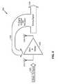
- FIG. 1is a block diagram of an exemplary enclosure of an illustrative repeater in accordance with the herein described systems and methods.
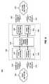
- FIG. 2is a block diagram of exemplary signal propagation for an exemplary RF repeater performing feedback cancellation in accordance with the herein described systems and methods.
- FIG. 3is a block diagram of exemplary antenna repeater components in accordance with the herein described systems and methods.
- FIG. 4is a block diagram of exemplary repeater components in accordance with the herein described systems and methods.
- FIG. 5is a block diagram of the cooperation of exemplary components of an illustrative RF repeater in accordance with the herein described systems and methods.
- FIG. 6is another block diagram of the cooperation of exemplary components of an illustrative RF repeater in accordance with the herein described systems and methods.
- FIG. 7is a block diagram of a frequency division duplexed (FDD) repeater having a dual band array in accordance with the herein described systems and methods.
- FDDfrequency division duplexed
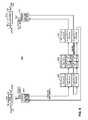
- FIG. 8is a block diagram of an exemplary FDD single band repeater having a digital interference cancellation system in accordance with the herein described systems and methods.
- FIG. 9is a block diagram of an exemplary FDD single band repeaters having a digital interference cancellation system and array in accordance with the herein described systems and methods.
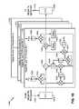
- FIG. 10is a block diagram showing the interaction of exemplary components having feedback cancellation and metric application mechanisms utilizing a filter bank approach in accordance with the herein described systems and methods.
- FIG. 11is a block diagram showing the interaction of exemplary components having feedback cancellation and metric application mechanisms utilizing a filter bank approach cooperating with an antenna array adaptively in accordance with the herein described systems and methods.
- FIG. 12is a graph diagram showing the impact of exemplary deployed feedback cancellation and metric application mechanisms in accordance with the herein described systems and methods.
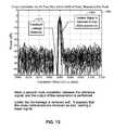
- FIG. 13is another graph diagram showing the impact of exemplary deployed feedback cancellation and metric application mechanisms in accordance with the herein described systems and methods.
- FIG. 14is another graph diagram showing the impact of exemplary deployed feedback cancellation and metric application mechanisms in accordance with the herein described systems and methods.
- FIGS. 15 and 15Aare flow diagrams of an exemplary method performed when deploying a filter bank approach to improve signal cancellation.
- FIG. 16illustrates an exemplary system that facilitates feedback loop cancellation in a repeater environment.
- a componentcan be, but is not limited to being, a process running on a processor, a processor, an object, an executable, a thread of execution, a program, and/or a computer.
- an application running on a computing device and the computing devicecan be a component.
- One or more componentscan reside within a process and/or thread of execution and a component can be localized on one computer and/or distributed between two or more computers.
- these componentscan execute from various computer readable media having various data structures stored thereon.
- the componentsmay communicate by way of local and/or remote processes such as in accordance with a signal having one or more data packets (e.g., data from one component interacting with another component in a local system, distributed system, and/or across a network such as the Internet with other systems by way of the signal).
- components of systems described hereinmay be rearranged and/or complemented by additional components in order to facilitate achieving the various aspects, goals, advantages, etc., described with regard thereto, and are not limited to the precise configurations set forth in a given figure, as will be appreciated by one skilled in the art.
- a wireless terminal or user equipmentcan also be called a system, subscriber unit, subscriber station, mobile station, mobile, mobile device, remote station, remote terminal, UE, user terminal, terminal, wireless communication device, user agent, or user device.
- a wireless terminal or UEcan be a cellular telephone, a cordless telephone, a Session Initiation Protocol (SIP) phone, a wireless local loop (WLL) station, a personal digital assistant (PDA), a handheld device having wireless connection capability, computing device, or other processing device connected to a wireless modem.
- SIPSession Initiation Protocol
- WLLwireless local loop
- PDApersonal digital assistant
- a base stationcan be utilized for communicating with wireless terminal(s) and can also be referred to as an access point, Node B, or some other terminology.
- various aspects or features described hereincan be implemented as a method, apparatus, or article of manufacture using standard programming and/or engineering techniques.
- article of manufactureas used herein is intended to encompass a computer program accessible from any computer-readable device, carrier, or media.
- computer-readable mediacan include but are not limited to magnetic storage devices (e.g., hard disk, floppy disk, magnetic strips, etc.), optical disks (e.g., compact disk (CD), digital versatile disk (DVD), etc.), smart cards, and flash memory devices (e.g., EPROM, card, stick, key drive, etc.).
- various storage media described hereincan represent one or more devices and/or other machine-readable media for storing information.
- a carrier wavecan be employed to carry computer-readable electronic data or instructions such as those used in transmitting and receiving voice mail, in accessing a network such as a cellular network, or in instructing a device to perform a specified function.
- machine-readable mediumrefers to various physical media capable of storing, containing, and/or carrying instruction(s) and/or data (but does not refer to vacuum).
- the herein described systems and methodscan be deployed as machine readable medium as part of wireless channels capable of storing, containing, and/or carrying instructions and/or data.
- the word “exemplary”is used herein to mean serving as an example, instance, or illustration. Any aspect or design described herein as “exemplary” is not necessarily to be construed as preferred or advantageous over other aspects or designs. Rather, use of the word exemplary is intended to present concepts in a concrete fashion.
- the term “or”is intended to mean an inclusive “or” rather than an exclusive “or”. That is, unless specified otherwise, or clear from context, “X employs A or B” is intended to mean any of the natural inclusive permutations. That is, if X employs A; X employs B; or X employs both A and B, then “X employs A or B” is satisfied under any of the foregoing instances.
- the articles “a” and “an” as used in this application and the appended claimsshould generally be construed to mean “one or more” unless specified otherwise or clear from context to be directed to a singular form.
- the terms to “infer” or “inference”refer generally to the process of reasoning about or inferring states of the system, environment, and/or user from a set of observations as captured via events and/or data. Inference can be employed to identify a specific context or action, or can generate a probability distribution over states, for example. The inference can be probabilistic—that is, the computation of a probability distribution over states of interest based on a consideration of data and events. Inference can also refer to techniques employed for composing higher-level events from a set of events and/or data. Such inference results in the construction of new events or actions from a set of observed events and/or stored event data, whether or not the events are correlated in close temporal proximity, and whether the events and data come from one or several event and data sources.
- CDMACode Division Multiple Access
- TDMATime Division Multiple Access
- FDMAFrequency Division Multiple Access
- OFDMAOrthogonal FDMA
- SC-FDMASingle-Carrier FDMA
- a CDMA networkmay implement a radio technology such as Universal Terrestrial Radio Access (UTRA), cdma2000, etc.
- UTRAincludes Wideband-CDMA (W-CDMA), TD-SCDMA, and TD-CDMA.
- cdma2000covers IS-2000, IS-95, and IS-856 standards.
- a TDMA networkmay implement a radio technology such as Global System for Mobile Communications (GSM).
- GSMGlobal System for Mobile Communications
- An OFDMA networkmay implement a radio technology such as Evolved UTRA (E-UTRA), IEEE 802.11, IEEE 802.16, IEEE 802.20, Flash-OFDM®, etc.
- E-UTRA, E-UTRA, and GSMare part of Universal Mobile Telecommunication System (UMTS).
- UMTSUniversal Mobile Telecommunication System
- LTELong Term Evolution
- UTRA, E-UTRA, GSM, UMTS, and LTEare described in documents from an organization named “3rd Generation Partnership Project” (3GPP).
- cdma2000is described in documents from an organization named “3rd Generation Partnership Project 2” (3GPP2).
- Temporal cancellers used in repeater environmentsare provided in related disclosures.
- a multi tap equalizer used in the feedback loop of the cancellercan provide some drawbacks since rate at which it may be adapted is dependent upon the number of time domain taps in the equalizer. While a solution that utilizes equalizer taps helps speed calculations significantly, mathematical complexity of a high number of taps can make speed of calculation or cost of implementation prohibitive for a large number of taps required for a very high degree of performance in the canceller.
- a feedback cancellation solutioncan rely on calculation of a number of equalizer taps in a closed form with simplified complexity. However, it would be beneficial to use a small number of taps, preferably a single one, and cancel very deeply but in a wider bandwidth than a single tap can provide.
- the herein described systems and methodsmay provide benefits compared to other feedback cancellation solutions by utilizing a filter bank approach that operatively provides cancellation depth of received transmitter leakage signal from a desired receive signal while providing a simplified method of calculating feedback equalizer weights in closed form.
- a repeater environmentis achieved by utilizing an FFT based filter bank approach that operatively decomposes a bandwidth signal to be repeated into a selected number of narrowband parallel repeater paths. These parallel narrowband repeater paths are able to use a single feedback weight in each canceller. Additionally, the cancellation loops can illustratively use only a single feedback weight for signal cancellation calculation, which can reduce need for calculation and inversion of a covariance matrix that can be currently required from closed form MMSE calculations. Further, the adaptive array can be optimized on a bin-by-bin basis using a least mean squared adaptive algorithm having a post cancellation correlation metric.
- the exemplary repeater environmentcan perform one or more operations/functions in conjunction with the filter bank approach to increase operational efficiencies including but not limited to digital filtering to allow some of the signal to pass, automatic gain control, and introducing a selected time delay to de-correlate transmit leakage signal from a desired received signal.
- an exemplary filter bank approachcan be used where circular convolution will approximate a linear convolution.
- an anti-distortion techniquecan be accomplished by providing a “zero pad” or appending a number of zero values onto end of a time block of data to be used in FFT block processing.
- a time domain impulse response of the filter functioncan also be zero padded to this same length and size of the FFT performed on the received block. Then in the frequency domain, these two sets of FFT results can be multiplied in parallel to perform filtering. This zero padding in the time domain prior to FFT processing can result in an interpolation in the frequency domain.
- the guideline for approximating linear convolution from the circular convolution process inherent in the frequency domain filtering approachis that FFT size is greater than or equal to number of time domain samples being utilized plus the length of the time domain impulse response of the filter minus one.
- FFT sizeis greater than or equal to number of time domain samples being utilized plus the length of the time domain impulse response of the filter minus one.
- values beyond number of time domain samples of the signalare set to zero to fill the FFT block to the proper size. The same requirement holds for the values beyond the length of the time domain impulse response samples of the filter response.
- the number of zeros to be appended on to the end of the signal samplescan be expressed as: NFFT ⁇ Ns.
- the number of zeros to be appended on the end of the impulse response samplescan be represented as: NFFT ⁇ K.
- Linear convolutioncan be achieved by performing an “overlap and add” or “overlap and save” as described in, Alan V. Oppenheim, Ronald W. Schafer, John R. Buck: Discrete-Time Signal Processing, Prentice Hall, ISBN 0-13-754920-2. Assuming the size of the FFT is equal to Ns+K ⁇ 1, the overlap and add approach involves, after performing the inverse FFT of the resulting (multiplied) FFT bins, taking the last NFFT ⁇ K ⁇ 1 samples from the last block processed in this manner, and adding them to the first NFFT ⁇ K ⁇ 1 samples of the current block.
- the first Ns samples from this “summed” blockcan be used as the time domain samples, while the last NFFT ⁇ K ⁇ 1 samples are retained to be summed to the next block. This accomplishes overlapping the tail of the filter impulse from the last block into the next block to allow the linear convolution to occur as if it had been filtered in the time domain.
- FIG. 1illustrates an exemplary enclosure for an illustrative repeater in accordance with various aspects described herein.
- a dipole dual patch antenna configuration along with repeater electronicscan be efficiently housed in a compact enclosure 100 as shown in FIG. 1 .
- Structure of the enclosure 100can be such that it can be intuitively oriented in at least one of two ways; however, instructions can guide a user in connection with placement of the enclosure to maximize signal reception.
- a ground plane 113incorporated with a printed circuit board (PCB) for the repeater electronics can be arranged between and parallel to two patch antennas 114 and 115 using, for example, standoffs 120 .
- An isolation fence 112can be employed to improve isolation in many instances.
- Each of the patch antennas 114 and 115can be arranged, for example, parallel to the ground plane 113 and can be printed on wiring board or the like, can be constructed of a stamped metal portion embedded in a plastic housing, or can be fabricated differently.
- a planar portion of the PCB associated with the ground plane 113can include a dipole antenna 111 configured, for example, as an embedded trace on the PCB.
- the patch antennas 114 and 115are vertically polarized and the dipole antenna 111 is horizontally polarized, although other embodiments can be used.
- a combination of non-overlapping antenna patterns and opposite polarizationscan be utilized to achieve approximately 40 dB or more of isolation between the receiving and transmitting antennas in a dual dipole dual patch antenna.
- one of the transmitter and the receiveruses one of two dual switched patch antennas having vertical polarization for communication with an access point, while the other of the of the transmitter and the receiver employs the dipole antenna having horizontal polarization.
- This approachwould be particularly applicable when the repeater is meant to repeat an indoor network signal to indoor clients.
- pattern of the antennas transmitting to the clientswould typically need to be generally omni-directional, requiring use of the dual dipole antennas, as direction to the clients is unknown.
- FIG. 2depicts an illustrative block diagram of an exemplary signal flow within illustrative repeater environment 200 .
- a weak received signal (the desired received signal) 220can be received by antenna element 210 , and act as input to gain and delay component 205 .
- Gain and delay component 205can process the weak received signal 220 to produce strong signal 230 as an output from antenna element 215 .
- a transmit signal leakage into receiver 225can also act as input to gain and delay 205 at antenna element 210 for use when processing the weak received signal 220 to generate strong signal 230 .
- the transmit leakage signal into the receiver 225can be generated by a feedback cancellation loop (not shown) operatively coupled to the antenna elements 210 and 215 . That is, the feedback cancellation loop generates a signal to be transmitted by the repeater, some of which is received by receiver 225 as a transmit leakage signal.
- FIG. 3illustrates interaction of antenna elements of an exemplary repeater environment 300 .
- Exemplary repeater environment 300comprises printed circuit board 330 which includes dipole antennas 305 and 320 , and further includes patch antennas 310 and 315 .
- the dipole/patch antenna combinationcan achieve selected isolation between transmit and receive channels to allow for deployment of desired feedback cancellation.
- the antenna configuration of FIG. 3is an example of a configuration of the antenna arrays that may be used in other embodiments described herein (where, e.g., patch antenna 310 is part of one antenna array and patch antenna 315 is part of the other antenna array).
- FIG. 4illustrates one side of another antenna configuration for use in providing selected isolation for an exemplary repeater.
- Antenna configuration 400comprises PCB board 405 having one or more patch antennas 410 and 415 mounted thereto Note that typically there would be a like number of antenna patches on the opposite side of PCB and typically orientated in an opposite or advantageous polarization when compared to the polarization of antennas 410 and 415 , such that a sufficient or even maximum amount of isolation is achieved between the antennas on opposite sides of the PCB.
- PCB board 405can comprise one or more patch antennas 410 and 415 in various configurations and have more than one pair of patch antennas as well as an uneven number of respective patch antennas that make up a superset thereof.
- Antenna configuration 400can with the deployment of patch antennas 410 and 415 along with a like number of antenna on the opposite side of the PCB provide selected isolation between a transmit and receive channel (e.g., transmit channels operatively coupled to one or more patch antennae and receive channels operatively coupled to one or more patch antennae) to cooperate with isolation and amplification provided by an exemplary cooperating feedback cancellation loop (e.g., feedback cancellation loop operatively coupled to an antenna array).
- a transmit and receive channele.g., transmit channels operatively coupled to one or more patch antennae and receive channels operatively coupled to one or more patch antennae
- an exemplary cooperating feedback cancellation loope.g., feedback cancellation loop operatively coupled to an antenna array.
- FIG. 4shows another example of antenna arrays that can be used in embodiments described herein.
- FIG. 5shows exemplary repeater environment 500 operative to perform signal conditioning and amplification using one or more antenna arraya.
- Exemplary repeater environment 500comprises a first antenna array 505 having antenna elements 510 and 515 , second antenna array having antenna elements 530 and 535 , processing circuitry 545 comprising multiple transceiver circuit 520 and controller 525 .
- the antenna arrays 505 and 540can cooperate with multiple transceiver circuit 520 which cooperates with controller 525 as part of operations of exemplary repeater environment 500 .
- Signalscan be received by antenna arrays 505 and 540 and passed to processing circuitry 545 for signal conditioning and processing and then passed back to antenna arrays 505 and 540 for communication with one or more cooperating components (e.g., base station of a CDMA wireless communications network).
- cooperating componentse.g., base station of a CDMA wireless communications network
- antenna arrays 505 and 540can comprise additional antenna elements as required to perform method(s) as described infra to achieve adaptive feedback cancellation realized by cooperation of one or more antenna arrays and the application of one or more metrics, such as one or more correlation results.
- the number and configuration of the antenna arrays described hereinare merely illustrative as the herein described systems and methods contemplate use of varying number of antenna arrays having varying configurations and comprising varying number of antenna elements.
- FIG. 6illustrates interaction of exemplary repeater environment 600 .
- Exemplary repeater environment 600comprises processing circuitry 620 comprising antenna array 645 comprising first antenna 625 and fourth antenna 640 , shielded multiple transceiver element 630 , and antenna array 650 comprising second antenna element 660 and third antenna element 655 .
- downlink signals 610 originating from first network 605can be processed by processing circuitry 620 to generate repeated downlink signals 665 for communication to second network 675
- uplink signals originating from second network 675can be processed by processing circuitry 620 to generate repeated uplink signals 615 for communication to first network 605 .
- Configuration and orientation of the antenna arrays 645 and 650promote selected isolation of the unconditioned uplink and downlink signals provided to processing circuitry 620 and promote desired amplification and gain of such signals.
- exemplary repeater environment 600can comprise additional antenna elements as required to perform method(s) as described herein to achieve adaptive feedback cancellation realized by cooperation of one or more antenna arrays and the application of correlated metric.
- number and configuration of the antenna arrays described hereinare merely illustrative as the herein described systems and methods contemplate use of varying number of antenna arrays having varying configurations and comprising varying number of antenna elements.
- FIG. 7is a block diagram of a four-antenna, multiple-transceiver device 700 configured to operate in multiple bands in accordance with various illustrative implementations. This device 700 can transmit signals freely across two different bands using a variable configuration of the available antennae.
- the device 700can include a shielded multiple-transceiver element 701 having a first side 710 and a second side 712 .
- the shielded multiple-transceiver element 701includes first band transceivers 732 and 748 , first band baseband circuitry 734 , second band transceivers 750 and 754 , second band baseband circuitry 752 , duplexers 724 , 726 , 728 , 730 , 738 , 740 , 744 , and 746 ; diplexers 720 , 722 , 736 , and 742 ; the first side 710 includes antennae 706 and 708 ; and the second side 712 includes antennae 714 and 716 .
- the device 700includes at least one electromagnetic isolation element, as described above, providing electromagnetic (EM) isolation between the antennae 706 and 708 on the first side 710 , and the antennae 714 and 716 on the second side 712 .
- EMelectromagnetic
- the antenna 706can send or receive signals 702 ; the antenna 708 can send or receive signals 704 ; the antenna 714 can send or receive signals 756 ; and the antenna 716 can send or receive signals 718 .
- These antennae 706 , 708 , 714 , and 716may be planar (e.g., patch) antennae, or any other desirable antenna types that may be effectively isolated from each other.
- the first band transceiver 732is connected to the antennae 706 and 708 through the duplexers 724 , 726 , 728 , and 730 , and the diplexers 720 , and 722 to send or receive data via the antennae 706 and 708 .
- the first band transceiver 748is connected to antennae 714 and 742 through duplexers 738 , 740 , 744 , and 746 , and diplexers 736 , and 742 to send or receive data via antennae 714 and 716 .
- the first band baseband circuitry 734is connected between first band transceiver 732 and first band transceiver 748 to provide communication between these two circuits.
- the second band transceiver 750is connected to antennae 706 and 708 through duplexers 728 and 730 , and diplexers 720 and 722 to send or receive data via antennae 706 and 708 .
- the second band transceiver 754is connected to antennae 714 and 716 through duplexers 738 and 740 , and diplexers 736 and 742 to send or receive data via antennae 714 and 716 .
- the second band baseband circuitry 752is connected between second band transceiver 750 and second band transceiver 754 to provide communication between these two circuits.
- Diplexers 720 , 722are connected between antennae 706 and 708 , and duplexers 724 , 726 , 728 , and 730 . They illustratively operate to determine which signals will be passed between antennae 706 and 708 and first band transceiver 732 , and between antennae 706 and 708 and second band transceiver 750 .
- Diplexers 720 , 722are configured to split signals based on frequency, passing signals of a first frequency band to/from duplexers 724 and 726 , and passing signals of a second frequency band to/from duplexers 728 and 730 .
- Duplexers 726 , 728are connected between diplexers 720 , 722 , and first band transceiver 732 ; and duplexers 728 , 730 are connected between diplexers 720 , 722 , and second band transceiver 750 .
- These duplexers 724 , 726 , 728 , 730serve to route signals of slightly different frequencies within the first or second band, respectively, to properly direct transmitted or received signals between first and second band transceivers 732 and 750 and diplexers 720 , 722 .
- Diplexers 738 , 742are connected between antennae 714 and 716 , and duplexers 738 , 740 , 744 , and 746 . They operate, for example, to determine which signals will be passed between antennae 714 and 716 and first band transceiver 748 , and between antennae 714 and 716 and second band transceiver 754 .
- the diplexers 738 , 742are configured to split signals based on frequency, passing signals of the second frequency band to/from duplexers 738 and 740 , and passing signals of the first frequency band to/from duplexers 744 and 746 .
- Duplexers 738 , 740are connected between diplexers 736 , 742 , and second band transceiver 754 ; and duplexers 744 , 746 are connected between diplexers 736 , 742 , and first band transceiver 748 .
- These duplexers 738 , 740 , 744 , 746serve to route signals of slightly different frequencies within the first or second band, respectively, to properly direct transmitted or received signals between first and second band transceivers 748 and 754 and diplexers 736 , 742 .
- duplexers 724 , 726 , 728 , 730 , 738 , 740 , 744 , and 746 , or diplexers 720 , 722 , 736 , and 742may be eliminated, since in some embodiments, certain permutations of band and antenna may be prohibited.
- signals from different bandscan be specifically assigned to certain transmission orientations.
- outputs of duplexers 724 , 726 , 728 , 730 , 738 , 740 , 744 , and 746can be directly connected to antennae 706 , 708 , 714 , or 716 .
- the first bandcould be designated to transmit/receive using a horizontal orientation
- the second bandcould be designated to transmit/receive using a vertical orientation.
- antennaethat are separate from a PCB
- alternate embodimentscould form the antennae directly on the opposite sides of the PCB.
- insulating layers within the PCBcan form the required non-conductive support members to separate the antennae from the ground plane.
- the transceiverwill likely be formed off of the PCB, and connected to the antennae by wiring on the PCB. This sort of integrated structure can provide for a more compact device.
- FIG. 8illustrates exemplary repeater environment 800 operative to deploy an FDD single band with digital interference cancellation system in accordance with performing the exemplary method(s) described herein.
- exemplary repeater environment 800comprises duplexer 804 operatively coupled to an antenna element operative to receive signals from base station 802 and providing input signals to transceiver 806 and is operative to receive signals for processing from transceiver 8066 .
- exemplary repeater environmentcomprises digital repeater baseband component 808 operatively coupled to transceiver 806 and transceiver 810 which is operatively coupled to duplexer 812 .
- duplexeris operatively coupled to an antenna element that allows for the communication of signals to a cooperating subscriber component 814 (e.g., mobile handset).
- the incident and transmitted signalscan be processed by exemplary repeater environment 800 such that an exemplary feedback cancellation method(s) described herein.
- FIG. 9illustrates exemplary repeater environment 900 operative to deploy an FDD single band with digital interference and an antenna array in accordance with the performing the exemplary method(s) described herein.
- exemplary repeater environment 900comprises duplexers 904 , 906 , 914 , and 916 ; transceivers 908 and 912 ; and digital repeater base band 910 .
- Duplexers 904 , 906 , 914 , and 96can be operatively coupled to one or more antenna elements that can receive/transmit signals from base station 902 and subscriber component 918 .
- the incident and transmitted signalscan be processed by exemplary repeater environment 900 according to the exemplary feedback cancellation method(s) described herein.
- FIG. 10is a block diagram showing interaction of exemplary components of an illustrative repeater environment 1000 operative to perform the exemplary method(s) described in herein.
- FIG. 10shows an illustrative implementation of an exemplary repeater environment 1000 deploying weighting calculations and applying metrics as part of a feedback loop cancellation technique.
- Exemplary repeater environment 1000is operative to execute one or more digital receive and transmit processes bins as described by Bin 1 1005 , Bin 2 1010 , Bin 3 1015 , up to Bin N 1020 .
- the inputs and outputs of the digital receive and transmit process bincan comprise fast Fourier transform (FFT) modules 1025 and 1030 .
- FFTfast Fourier transform
- signalscan be incident on antenna element 1035 for processing by repeater environment 1000 .
- the received signalcan be processed according to FFT module 1025 of one or more receive and transmit process bins Bin 1 1005 to Bin N 1020 , the output of which can be passed along to the input of multiplier 1038 , subtraction component 1036 , and multiplier component 1034 .
- the output of multiplier componentcan act as input to adder component 1032 to generate selected values for use in filter bank operations.
- the output of subtraction block 1036can act as input to multiplier 1056 which takes the subtracted signal (e.g., a subtraction of the output of FFT module 1025 and division module 1044 ) and multiply by calculated weights from weight block 1054 .
- multiplier 1056can act as input to multiplier 1060 the output of multiplier 1060 can act as input to summer 1058 which generates a selected value for use in filter bank operations.
- the output of multiplier 1054can also act as input to delay block 1062 that can provide a selected time delay to the processed signal according to one or more filter bank operations.
- the output of delay block 1062can act as input to multiplier 1038 that multiplies the time delay with the output of FFT module 1025 .
- the output of multiplier block 1038can act as input to adder block 1040 , the output of adder block 1040 acting as input to multiplier block 1042 operative to multiply the time delay from delay block 1062 with the output of adder block 1040 .
- the output of multiplier block 1042can act as input to division block 1044 which can divide the output of multiplier block 1042 by summer block 1046 , the output of division block 1044 can act as input to subtraction block 1036 .
- the output of delay block 1062can act as input to multiplier 1050 which can multiply the time delay from delay block 1062 with the output of subtraction block 1036 .
- the output of multiplier block 1050can act as input of adder block 1052 that generates selected values for filter bank operations. Further, the output of delay block 1062 can act as input to multiplier 1048 which multiplies the delay block output with itself. The output of multiplier block 1048 can act as input to adder block 1046 , the output of adder block 1046 can act as input to division block 1044 . Additionally, the output of multiplier block 1056 can act as input to FFT block 1030 that can perform one or more inverse FFT operations. The output of FFT block 1030 can be communicated to one or more cooperating components (e.g., subscriber module) using antenna element 1040 .
- cooperating componentse.g., subscriber module
- FIG. 11is a block diagram showing the interaction of exemplary components and exemplary signal pathways to perform the exemplary methods described herein as performed by exemplary repeater environment 1100 .
- a signalcan received on one of antenna elements 1112 and 1116 can be processed by FFT modules 1110 or 1114 , respectively.
- antenna elements 1176 and 1172can cooperate with FFT modules 1174 and 1170 , respectively.
- the multiple antenna elements 1112 and 1116(as well as 1176 and 1172 ) can comprise an adaptive antenna array operable to cooperate with receive and transmit process bins Bin 1 1102 , Bin 2 1104 , Bin 3 1106 , up to process Bin N 1108 .
- the process binscan represent parallel processing of an incident signal using a filter bank approach such that that a wide band incident signal can be decomposed into one or more narrow band blocks which are processed in the frequency domain according to the processing components described in each of the exemplary processing bins Bin 1 1102 , Bin 2 1104 , Bin 3 1106 , up to Bin N 1008 and signal pathways amongst the processing components as shown by the arrowed lines.
- the processing componentscan comprise weight blocks 1118 , 1168 , 1160 ; multipliers 1120 , 1130 , 1124 , 1132 , 1140 , 1144 , 1146 , 1152 , 1154 , 1164 , and 1162 ; adder blocks 1128 , 1134 , 1148 , 1142 and 1156 .
- Also present among the processing componentsare division block 1138 , subtraction block 1136 , and summer blocks 1122 , and 1158 .
- the illustrative processing componentscooperate as shown by the arrowed lines to perform one or more method for the execution of filter bank approach in promoting signal cancellation between the transmitter components and receiver components of exemplary repeater environment 1100 .
- FIG. 12is graphical diagram showing the cross correlation of a plurality of frequency receive and transmit processing bins (e.g., as shown in FIGS. 10 and 11 and described in the associated text).
- the feedback leakage 1205spikes in relation to the desired signal 1210 , rendering the desired signal drowned by the feedback leakage signal (e.g., signal leaking from the transmit side back to the receiver of an exemplary repeater).
- the power of the feedback leakage signal 1205is around 50 dB where the desired signal is 1210 shown to have a power level of 25 dB.
- the difference between the feedback leakage signal 1205 and the desired signal 1210can significantly impact the performance of the exemplary repeater.
- FIG. 13is a graphical diagram showing a graph plot of the performance gain realized with the application of an exemplary filter bank approach in reducing the impact of the feedback cancellation signal on an exemplary repeater environment.
- the feedback leakage signalis removed as shown by feedback leakage removed box 1310 .
- the desired signal 1320is shown to have a performance improvement of over 20 dB with the application of the filter bank feedback cancellation processing techniques described herein.
- FIG. 14is a three dimensional graphical diagram showing a graph plot of the processing performed by N number of processing bins (X axis) as performed in parallel.
- an input signal 1410can be discretely decomposed and processed in parallel bins according to the filter bank approach described herein.
- the decomposed signale.g., broken down into discrete narrow bands
- the decomposed signalcan be correlated (Y axis) as is shown in FIG. 14 such that the desired signal 1410 can be processed and supported to realize performance improvement (e.g., power improvement—Z axis).
- the peak of the correlation at point 1410shows the specific correlation maximum between the reference transmit signal and the received desired signal summed with the transmitted leakage signal.
- FIG. 12shows the side view on the correlation offset axis. The peak correlation is aligned with point 1205 on FIG. 12 .
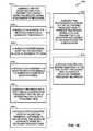
- FIG. 15is a flow diagram of exemplary processing performed in the application of a filter bank when performing feedback cancellation. Processing begins at block 1502 where repeater transmitter leakage signals and desired received signals are received on M receivers. Processing then proceeds to block 1504 where Ns number of samples are stored as M number of receiver time blocks from the receivers. Zero-padding then is applied at block 1506 where (NFFT ⁇ Ns) zeros are appended onto the Ns time samples from the receivers. An NFFT point FFT is then performed on the zero appended receive block at block 1508 .
- Complex spatial weights arrays of length NFFTe.g., M, 1 ⁇ NFFT complex arrays
- the composite weighted receiver frequency binsare processed by a leakage cancellation block in parallel to produce the post cancellation receiver frequency bin at block 1514 .
- the time constant associated with the update of feedback valuescan illustratively maintain a time constant of Tc.
- the calculations of the updated values calculated by the parallel leakage cancellation blockcan be performed by utilizing the single tap MMSE solution using serial samples from individual corresponding frequency bins for the frequency domain signals. Processing continues to FIG. 15A as described by block 1518 .
- FIG. 15Ais a flow diagram describing the continuation of the processing described in a FIG. 15 . As is shown processing continues from block 1518 of FIG. 15 at block 1520 and proceeds. From block 1520 , processing continues to block 1522 where the frequency domain base band filtering and AGC coefficient multiplier block multiplies a set of NFFT coefficients by the post cancellation receive frequency bins to produce the filtered AGC output frequency bins.
- Processingthen proceeds to block 1524 where the automatic gain control calculation block utilized one or more of the pre-correlation leakage frequency bin metric, residual leakage correlation frequency bin metric, power in frequency bin, power out frequency bin metric, and isolation margin per frequency bin metric to perform an automatic gain control calculation on a bin by bin basis as well as the frequency domain filter response array to provide an updated AGC and filter coefficient array.
- the spatial weighting blockcalculates new receiver and transmitter complex spatial weights arrays for the M receivers and N transmitters (M, NFFT arrays, and N, NFFT arrays) based on an LMS algorithm or other adaptive algorithm utilizing residual leakage correlation metric frequency bins operating in parallel and a convergence time (e.g., of greater than 10 times Tc on each of the individual FFT bins).
- the spatial weighting blockapplies N, NFFT complex spatial transmitter weight arrays respectively to N copies of the Filtered AGC output frequency bins to produce N weighted transmit frequency bin arrays at block 1528 .
- a NFFT point inverse FFTis then performed at block 1530 on N weighted transmit frequency bin arrays to produce N time domain series.
- Processingthen proceeds to block 1532 where an overlap add process is performed on each of the N time domain series to produce N transmit time series of length Ns time samples.
- the N repeater transmit signalsare then received at block 1536 at the M number of receivers to form M repeater transmit leakage signals summed with the M desired receive signals.
- FIG. 16illustrates a system 1600 that facilitates feedback loop cancellation in a repeater environment.
- the systemincludes a module 1610 for receiving repeater transmitter leakage signal and receive signal at M number of receivers; a module 1620 for storing the received signals as a number of the signals; a module for performing an FFT on the received blocks to generate FFT bins which will also provide the zero padding functionality; a module 1640 for combining the weighted receiver signals to generate a composite weighted signal; a module 1650 for producing a post-cancellation receive frequency bin for use in generating an automatic gain control (AGC) output frequency bins; a module 1660 for calculating updated values for feedback loop based on one or more time series of composite weighted receiver frequency bins; a module 1670 for applying spatial weighting to the AGC output frequency bins to produce weighted transmit frequency bin arrays; a module 1680 for performing an inverse FFT on the transmit frequency bins, and performing the overlap add functionality, to produce time domain series that are transmitted to M receivers and
- the systems and methods for efficiently representing knowledge of the herein described systems and methodsmay also be applied to the context of resolving in memory data on the same provider.
- the in memory datamay not be backed by a physical store, e.g., it might be used in a graph solver on the CPU to synchronize nodes.
- the herein described systems and methodsmay also be applied in the context of scene graphs, especially as they become more distributed on multi-core architectures and calculations are written directly to an in memory data structure such as a volumetric texture.
- an appropriate API, tool kit, driver code, operating system, control, standalone or downloadable software object, etc.which enables applications and services to use the systems and methods for representing and exchanging knowledge in accordance with the herein described systems and methods.
- the herein described systems and methodscontemplate the use of the herein described systems and methods from the standpoint of an API (or other software object), as well as from a software or hardware object that performs the knowledge exchange in accordance with the herein described systems and methods.
- various implementations of the herein described systems and methodsmay have aspects that are wholly in hardware, partly in hardware and partly in software, as well as in software.
- exemplaryis used herein to mean serving as an example, instance, or illustration.
- the subject matter disclosed hereinis not limited by such examples.
- any aspect or design described herein as “exemplary”is not necessarily to be construed as preferred or advantageous over other aspects or designs, nor is it meant to preclude equivalent exemplary structures and techniques known to those of ordinary skill in the art.
- the terms “includes,” “has,” “contains,” and other similar wordsare used in either the detailed description or the claims, for the avoidance of doubt, such terms are intended to be inclusive in a manner similar to the term “comprising” as an open transition word without precluding any additional or other elements.
- the underlying conceptsmay be applied to any computing device or system in which it is desirable to synchronize data with another computing device or system.
- the synchronization processes of the herein described systems and methodsmay be applied to the operating system of a computing device, provided as a separate object on the device, as part of another object, as a reusable control, as a downloadable object from a server, as a “middle man” between a device or object and the network, as a distributed object, as hardware, in memory, a combination of any of the foregoing, etc.
- a componentmay be, but is not limited to being, a process running on a processor, a processor, an object, an executable, a thread of execution, a program, and/or a computer.
- a componentmay be, but is not limited to being, a process running on a processor, a processor, an object, an executable, a thread of execution, a program, and/or a computer.
- an application running on computer and the computercan be a component.
- One or more componentsmay reside within a process and/or thread of execution and a component may be localized on one computer and/or distributed between two or more computers.
- the methods and apparatus of the herein described systems and methodsmay take the form of program code (i.e., instructions) embodied in tangible media, such as floppy diskettes, CD-ROMs, hard drives, or any other machine-readable storage medium, wherein, when the program code is loaded into and executed by a machine, such as a computer, the machine becomes an apparatus for practicing the herein described systems and methods.
- program code execution on programmable computersthe computing device generally includes a processor, a storage medium readable by the processor (including volatile and non-volatile memory and/or storage elements), at least one input device, and at least one output device.
- One or more programs that may implement or utilize the synchronization services and/or processes of the herein described systems and methods, e.g., through the use of a data processing API, reusable controls, or the like,are preferably implemented in a high level procedural or object oriented programming language to communicate with a computer system.
- the program(s)can be implemented in assembly or machine language, if desired.
- the languagemay be a compiled or interpreted language, and combined with hardware implementations.
- the methods and apparatus of the herein described systems and methodsmay also be practiced via communications embodied in the form of program code that is transmitted over some transmission medium, such as over electrical wiring or cabling, through fiber optics, or via any other form of transmission, wherein, when the program code is received and loaded into and executed by a machine, such as an EPROM, a gate array, a programmable logic device (PLD), a client computer, etc., the machine becomes an apparatus for practicing the herein described systems and methods.
- a machinesuch as an EPROM, a gate array, a programmable logic device (PLD), a client computer, etc.
- PLDprogrammable logic device
- client computeretc.
- the program codeWhen implemented on a general-purpose processor, the program code combines with the processor to provide a unique apparatus that operates to invoke the functionality of the herein described systems and methods.
- any storage techniques used in connection with the herein described systems and methodsmay invariably be a combination of hardware and software.
- the disclosed subject mattermay be implemented as a system, method, apparatus, or article of manufacture using standard programming and/or engineering techniques to produce software, firmware, hardware, or any combination thereof to control a computer or processor based device to implement aspects detailed herein.
- article of manufacture(or alternatively, “computer program product”) where used herein is intended to encompass a computer program accessible from any computer-readable device, carrier, or media.
- computer readable mediacan include but are not limited to magnetic storage devices (e.g., hard disk, floppy disk, magnetic strips . . . ), optical disks (e.g., compact disk (CD), digital versatile disk (DVD) . . . ), smart cards, and flash memory devices (e.g., card, stick).
- a carrier wavecan be employed to carry computer-readable electronic data such as those used in transmitting and receiving electronic mail or in accessing a network such as the Internet or a local area network (LAN).
- various portions of the disclosed systems above and methods belowmay include or consist of artificial intelligence or knowledge or rule based components, sub-components, processes, means, methodologies, or mechanisms (e.g., support vector machines, neural networks, expert systems, Bayesian belief networks, fuzzy logic, data fusion engines, classifiers . . . ).
- Such componentscan automate certain mechanisms or processes performed thereby to make portions of the systems and methods more adaptive as well as efficient and intelligent.
- exemplary network environments of the herein described systems and methodsare described in the context of a networked environment, such as a peer to peer networked environment, one skilled in the art will recognize that the herein described systems and methods are not limited thereto, and that the methods, as described in the present application may apply to any computing device or environment, such as a gaming console, handheld computer, portable computer, etc., whether wired or wireless, and may be applied to any number of such computing devices connected via a communications network, and interacting across the network.
- a variety of computer platformsincluding handheld device operating systems and other application specific operating systems are contemplated, especially as the number of wireless networked devices continues to proliferate.
- the herein described systems and methodsare not so limited, but rather may be implemented in any language to provide methods for representing and exchanging knowledge for a set of nodes in accordance with the herein described systems and methods. Still further, the herein described systems and methods may be implemented in or across a plurality of processing chips or devices, and storage may similarly be effected across a plurality of devices. Therefore, the herein described systems and methods should not be limited to any single embodiment, but rather should be construed in breadth and scope in accordance with the appended claims.
Landscapes
- Engineering & Computer Science (AREA)
- Computer Networks & Wireless Communication (AREA)
- Signal Processing (AREA)
- Radio Relay Systems (AREA)
- Cable Transmission Systems, Equalization Of Radio And Reduction Of Echo (AREA)
- Mobile Radio Communication Systems (AREA)
Abstract
Description
NFFT>=Ns+K−1,
Where, NFFT is the FFT size, Ns can be the number of time samples in the block of signal samples to be processed, and where K is the number of time samples in the impulse response of the filter being used to filter the signal.
The number of zeros to be appended on to the end of the signal samples can be expressed as:
NFFT−Ns.
The number of zeros to be appended on the end of the impulse response samples can be represented as:
NFFT−K.
Claims (22)
Priority Applications (1)
| Application Number | Priority Date | Filing Date | Title |
|---|---|---|---|
| US12/041,611US8116239B2 (en) | 2007-03-02 | 2008-03-03 | Use of a filterbank in an adaptive on-channel repeater utilizing adaptive antenna arrays |
Applications Claiming Priority (2)
| Application Number | Priority Date | Filing Date | Title |
|---|---|---|---|
| US90436807P | 2007-03-02 | 2007-03-02 | |
| US12/041,611US8116239B2 (en) | 2007-03-02 | 2008-03-03 | Use of a filterbank in an adaptive on-channel repeater utilizing adaptive antenna arrays |
Publications (2)
| Publication Number | Publication Date |
|---|---|
| US20080225930A1 US20080225930A1 (en) | 2008-09-18 |
| US8116239B2true US8116239B2 (en) | 2012-02-14 |
Family
ID=39564244
Family Applications (7)
| Application Number | Title | Priority Date | Filing Date |
|---|---|---|---|
| US12/041,603Expired - Fee RelatedUS8599906B2 (en) | 2007-03-02 | 2008-03-03 | Closed form calculation of temporal equalizer weights used in a repeater transmitter leakage cancellation system |
| US12/041,598Active2029-08-17US7907891B2 (en) | 2007-03-02 | 2008-03-03 | Physical layer repeater utilizing real time measurement metrics and adaptive antenna array to promote signal integrity and amplification |
| US12/041,621Expired - Fee RelatedUS8121535B2 (en) | 2007-03-02 | 2008-03-03 | Configuration of a repeater |
| US12/041,611Expired - Fee RelatedUS8116239B2 (en) | 2007-03-02 | 2008-03-03 | Use of a filterbank in an adaptive on-channel repeater utilizing adaptive antenna arrays |
| US12/041,617Expired - Fee RelatedUS7911985B2 (en) | 2007-03-02 | 2008-03-03 | Automatic gain control and filtering techniques for use in on-channel repeater |
| US12/041,615Expired - Fee RelatedUS8619837B2 (en) | 2007-03-02 | 2008-03-03 | Use of adaptive antenna array in conjunction with an on-channel repeater to improve signal quality |
| US12/041,626Expired - Fee RelatedUS7907513B2 (en) | 2007-03-02 | 2008-03-03 | Superimposed composite channel filter |
Family Applications Before (3)
| Application Number | Title | Priority Date | Filing Date |
|---|---|---|---|
| US12/041,603Expired - Fee RelatedUS8599906B2 (en) | 2007-03-02 | 2008-03-03 | Closed form calculation of temporal equalizer weights used in a repeater transmitter leakage cancellation system |
| US12/041,598Active2029-08-17US7907891B2 (en) | 2007-03-02 | 2008-03-03 | Physical layer repeater utilizing real time measurement metrics and adaptive antenna array to promote signal integrity and amplification |
| US12/041,621Expired - Fee RelatedUS8121535B2 (en) | 2007-03-02 | 2008-03-03 | Configuration of a repeater |
Family Applications After (3)
| Application Number | Title | Priority Date | Filing Date |
|---|---|---|---|
| US12/041,617Expired - Fee RelatedUS7911985B2 (en) | 2007-03-02 | 2008-03-03 | Automatic gain control and filtering techniques for use in on-channel repeater |
| US12/041,615Expired - Fee RelatedUS8619837B2 (en) | 2007-03-02 | 2008-03-03 | Use of adaptive antenna array in conjunction with an on-channel repeater to improve signal quality |
| US12/041,626Expired - Fee RelatedUS7907513B2 (en) | 2007-03-02 | 2008-03-03 | Superimposed composite channel filter |
Country Status (10)
| Country | Link |
|---|---|
| US (7) | US8599906B2 (en) |
| EP (7) | EP2119042A2 (en) |
| JP (7) | JP5134016B2 (en) |
| KR (10) | KR101061753B1 (en) |
| CN (7) | CN101675633A (en) |
| BR (6) | BRPI0808540A2 (en) |
| CA (7) | CA2677917C (en) |
| RU (7) | RU2420886C1 (en) |
| TW (7) | TWI370637B (en) |
| WO (7) | WO2008109573A2 (en) |
Cited By (10)
| Publication number | Priority date | Publication date | Assignee | Title |
|---|---|---|---|---|
| US20080225929A1 (en)* | 2007-03-02 | 2008-09-18 | Qualcomm Incorporated | Closed Form Calculation of Temporal Equalizer Weights Used in a Repeater Transmitter Leakage Cancellation System |
| US20100105320A1 (en)* | 2008-10-23 | 2010-04-29 | Fujitsu Limited | Wireless relay device |
| US20100329229A1 (en)* | 2008-02-12 | 2010-12-30 | Dietmar Lipka | Single carrier frequency division multiple access technique |
| US20120014697A1 (en)* | 2009-05-26 | 2012-01-19 | Ming Zhao | Antenna device |
| US8422540B1 (en) | 2012-06-21 | 2013-04-16 | CBF Networks, Inc. | Intelligent backhaul radio with zero division duplexing |
| US20130222184A1 (en)* | 2007-05-21 | 2013-08-29 | Donald C.D. Chang | Receive only smart ground-terminal antenna for geostationary satellites in slightly inclined orbits |
| US8649418B1 (en) | 2013-02-08 | 2014-02-11 | CBF Networks, Inc. | Enhancement of the channel propagation matrix order and rank for a wireless channel |
| US20150092825A1 (en)* | 2013-09-27 | 2015-04-02 | Qualcomm Incorporated | Self-test using internal feedback for transmit signal quality estimation |
| US11368209B2 (en)* | 2019-05-30 | 2022-06-21 | Qualcomm Incorporated | Methods and apparatus for frequency translating repeaters |
| US12436230B2 (en)* | 2022-05-02 | 2025-10-07 | Denso Corporation | Radar device |
Families Citing this family (176)
| Publication number | Priority date | Publication date | Assignee | Title |
|---|---|---|---|---|
| IT1403065B1 (en) | 2010-12-01 | 2013-10-04 | Andrew Wireless Systems Gmbh | DISTRIBUTED ANTENNA SYSTEM FOR MIMO SIGNALS. |
| US8121058B2 (en)* | 2002-12-10 | 2012-02-21 | Investors Life Insurance Corporation | Cognitive IP radio with repeaters |
| US7327803B2 (en) | 2004-10-22 | 2008-02-05 | Parkervision, Inc. | Systems and methods for vector power amplification |
| US7355470B2 (en) | 2006-04-24 | 2008-04-08 | Parkervision, Inc. | Systems and methods of RF power transmission, modulation, and amplification, including embodiments for amplifier class transitioning |
| US20130078934A1 (en) | 2011-04-08 | 2013-03-28 | Gregory Rawlins | Systems and Methods of RF Power Transmission, Modulation, and Amplification |
| US7911272B2 (en) | 2007-06-19 | 2011-03-22 | Parkervision, Inc. | Systems and methods of RF power transmission, modulation, and amplification, including blended control embodiments |
| US8334722B2 (en) | 2007-06-28 | 2012-12-18 | Parkervision, Inc. | Systems and methods of RF power transmission, modulation and amplification |
| US9106316B2 (en) | 2005-10-24 | 2015-08-11 | Parkervision, Inc. | Systems and methods of RF power transmission, modulation, and amplification |
| US8031804B2 (en) | 2006-04-24 | 2011-10-04 | Parkervision, Inc. | Systems and methods of RF tower transmission, modulation, and amplification, including embodiments for compensating for waveform distortion |
| US7937106B2 (en) | 2006-04-24 | 2011-05-03 | ParkerVision, Inc, | Systems and methods of RF power transmission, modulation, and amplification, including architectural embodiments of same |
| CN101553956B (en)* | 2006-12-11 | 2013-03-27 | 高通股份有限公司 | Multiple-antenna device having an isolation element |
| KR100879334B1 (en)* | 2007-03-06 | 2009-01-19 | (주)에어포인트 | Micro integrated interference elimination wireless relay device and method thereof |
| WO2008144017A1 (en) | 2007-05-18 | 2008-11-27 | Parkervision, Inc. | Systems and methods of rf power transmission, modulation, and amplification |
| AU2007353763B2 (en)* | 2007-05-22 | 2013-10-10 | Telstra Corporation Limited | A repeater system for extended cell coverage |
| US7876869B1 (en) | 2007-05-23 | 2011-01-25 | Hypers, Inc. | Wideband digital spectrometer |
| WO2008156800A1 (en) | 2007-06-19 | 2008-12-24 | Parkervision, Inc. | Combiner-less multiple input single output (miso) amplification with blended control |
| ES2330178B1 (en)* | 2007-06-25 | 2010-08-30 | Diseño De Sistemas En Silicio, S.A. | SINGLE REPEATER OF A SINGLE PORT. |
| US8548525B2 (en)* | 2007-06-28 | 2013-10-01 | Fimax Technology Limited | Systems and methods using antenna beam scanning for improved communications |
| CN101926100A (en)* | 2008-01-28 | 2010-12-22 | 诺基亚公司 | System for distributed beamforming of a communication system using relay nodes |
| US8116254B2 (en)* | 2008-01-31 | 2012-02-14 | Powerwave Technologies, Inc. | Wireless repeater with smart uplink |
| FR2928475B1 (en)* | 2008-03-05 | 2010-05-07 | Commissariat Energie Atomique | CONTACTLESS COMMUNICATION DEVICE. |
| KR101457704B1 (en)* | 2008-06-19 | 2014-11-04 | 엘지전자 주식회사 | Radio transceiver and relay station with it |
| US8249540B1 (en) | 2008-08-07 | 2012-08-21 | Hypres, Inc. | Two stage radio frequency interference cancellation system and method |
| EP2351255B1 (en)* | 2008-11-26 | 2012-10-10 | Andrew Wireless Systems GmbH | Single input single output repeater for relaying a multiple input multiple output signal |
| KR101544705B1 (en)* | 2008-12-29 | 2015-08-17 | 연세대학교 산학협력단 | A victim system detection device, a victim system detection method, a communication device, and a communication method |
| JP5165798B2 (en) | 2009-01-12 | 2013-03-21 | テレフオンアクチーボラゲット エル エム エリクソン(パブル) | System and method for canceling feedback interference |
| US8289901B2 (en)* | 2009-03-17 | 2012-10-16 | Cisco Technology, Inc. | Pinning and cascading avoidance in dynamic channel assignment for wireless LANS |
| JP5342294B2 (en)* | 2009-03-26 | 2013-11-13 | 京セラ株式会社 | Radio relay station and radio relay method |
| US8849190B2 (en)* | 2009-04-21 | 2014-09-30 | Andrew Llc | Radio communication systems with integrated location-based measurements for diagnostics and performance optimization |
| US9793982B2 (en) | 2009-04-21 | 2017-10-17 | Commscope Technologies Llc | System for automatic configuration of a mobile communication system |
| US8265546B2 (en) | 2009-05-11 | 2012-09-11 | Qualcomm Incorporated | Gain adjustment stepping control in a wireless repeater |
| US20100284447A1 (en)* | 2009-05-11 | 2010-11-11 | Qualcomm Incorporated | Frequency domain feedback channel estimation for an interference cancellation repeater including sampling of non causal taps |
| US20110116531A1 (en)* | 2009-05-11 | 2011-05-19 | Qualcomm Incorporated | Removal of multiplicative errors in frequency domain channel estimation for wireless repeaters |
| US9049065B2 (en)* | 2009-05-11 | 2015-06-02 | Qualcomm Incorporated | Removal of ICI/ISI errors in frequency domain channel estimation for wireless repeaters |
| US20110032849A1 (en)* | 2009-08-07 | 2011-02-10 | Fimax Technology Limited | Systems and methods for mitigating interference between access points |
| US8285221B2 (en)* | 2009-08-31 | 2012-10-09 | Motorola Mobility Llc | Scalable self-calibrating and configuring radio frequency head for a wireless communication system |
| JP2011055350A (en)* | 2009-09-03 | 2011-03-17 | Japan Radio Co Ltd | Radio relay device and delay wave canceling method |
| KR101301298B1 (en)* | 2009-11-30 | 2013-08-28 | 포항공과대학교 산학협력단 | Rf relay of full-duplex and method for reducing interference of em-level thereof |
| US8605604B1 (en)* | 2009-12-23 | 2013-12-10 | Marvell International Ltd. | WLAN module test system |
| WO2011082122A1 (en)* | 2009-12-28 | 2011-07-07 | Schlumberger Technology Corp. | Downhole data transmission system |
| US8731616B2 (en)* | 2009-12-29 | 2014-05-20 | Kathrein -Werke KG | Active antenna array and method for relaying first and second protocol radio signals in a mobile communications network |
| US9030363B2 (en)* | 2009-12-29 | 2015-05-12 | Kathrein-Werke Ag | Method and apparatus for tilting beams in a mobile communications network |
| US8542623B2 (en) | 2010-01-13 | 2013-09-24 | Qualcomm Incorporated | Use of RF reference in a digital baseband interference cancellation repeater |
| US8948063B2 (en)* | 2010-01-14 | 2015-02-03 | Qualcomm Incorporated | Method and system for real-time calibration and reporting of processing delay |
| IT1398025B1 (en) | 2010-02-12 | 2013-02-07 | Andrew Llc | DISTRIBUTED ANTENNA SYSTEM FOR MIMO COMMUNICATIONS. |
| US8548375B2 (en) | 2010-03-12 | 2013-10-01 | Qualcomm Incorporated | Gain control metric computation in a wireless repeater |
| US10270152B2 (en)* | 2010-03-31 | 2019-04-23 | Commscope Technologies Llc | Broadband transceiver and distributed antenna system utilizing same |
| US8611401B2 (en)* | 2010-04-01 | 2013-12-17 | Adeptence, Llc | Cancellation system for millimeter-wave radar |
| US8559485B2 (en) | 2010-04-08 | 2013-10-15 | Andrew Llc | Autoregressive signal processing for repeater echo cancellation |
| US8346160B2 (en) | 2010-05-12 | 2013-01-01 | Andrew Llc | System and method for detecting and measuring uplink traffic in signal repeating systems |
| US8837307B2 (en) | 2010-05-26 | 2014-09-16 | Qualcomm Incorporated | Two-way ranging messaging scheme |
| US8879407B2 (en) | 2010-05-26 | 2014-11-04 | Qualcomm Incorporated | Two-way ranging messaging scheme |
| US8886148B2 (en)* | 2010-05-26 | 2014-11-11 | Qualcomm Incorporated | Signal based gain control |
| US8812063B2 (en) | 2010-05-26 | 2014-08-19 | Qualcomm Incorporated | Signal characteristic-based leading edge detection |
| US8831141B2 (en) | 2010-06-25 | 2014-09-09 | Qualcomm Incorporated | Leading edge detection |
| US8630211B2 (en) | 2010-06-30 | 2014-01-14 | Qualcomm Incorporated | Hybrid radio architecture for repeaters using RF cancellation reference |
| US8477665B2 (en) | 2010-07-14 | 2013-07-02 | Qualcomm Incorporated | Method in a wireless repeater employing an antenna array for interference reduction |
| US8787248B2 (en)* | 2010-07-14 | 2014-07-22 | Qualcomm Incorporated | Method in a wireless repeater employing an antenna array including vertical and horizontal feeds for interference reduction |
| US8499021B2 (en) | 2010-08-25 | 2013-07-30 | Qualcomm Incorporated | Circuit and method for computing circular convolution in streaming mode |
| KR101496261B1 (en)* | 2010-09-13 | 2015-02-26 | 한국전자통신연구원 | Integrated terminal using supplementary information and communicating method thereof |
| KR20130099984A (en) | 2010-10-01 | 2013-09-06 | 앤드류 엘엘씨 | Distributed antenna system for mimo singnals |
| KR101157136B1 (en)* | 2011-01-04 | 2012-06-22 | 주식회사 에프티씨 | Multi-path repeater and control process of multi-path repeater |
| JP6138795B2 (en)* | 2011-01-19 | 2017-05-31 | インテル コーポレイション | Antenna array structure, device, and transmission / reception method |
| US8451930B2 (en)* | 2011-02-08 | 2013-05-28 | Mitsubishi Electric Research Laboratories, Inc. | Sparse channel estimation using order extension for frequency and time selective MIMO wireless communication networks |
| JP2012175542A (en)* | 2011-02-23 | 2012-09-10 | Japan Radio Co Ltd | Relay apparatus |
| ES2598827T3 (en) | 2011-03-28 | 2017-01-30 | Dolby Laboratories Licensing Corp. | Reduced complexity transformation for a low frequency effects channel |
| KR20120114969A (en) | 2011-04-08 | 2012-10-17 | 한국전자통신연구원 | Data processing method, equalizer and receiver |
| KR20140034895A (en) | 2011-06-02 | 2014-03-20 | 파커비전, 인크. | Antenna control |
| US8699943B2 (en)* | 2011-06-03 | 2014-04-15 | Andrew Llc | Mobile repeater system and method having geophysical location awareness without use of GPS |
| BR112013033527B8 (en) | 2011-06-27 | 2023-01-10 | Viavi Solutions Inc | METHOD FOR DETECTING DISPERSION IN DIGITAL CABLE SYSTEM, APPARATUS FOR IDENTIFYING DIGITAL CATV SIGNAL AND APPARATUS FOR DETERMINING WHETHER A RECEIVED SIGNAL IS A DIGITAL CATV IDENTIFICATION INSERTED BETWEEN ADJACENT DIGITAL CATV CHANNELS |
| US8467363B2 (en) | 2011-08-17 | 2013-06-18 | CBF Networks, Inc. | Intelligent backhaul radio and antenna system |
| CN106935983A (en) | 2011-09-08 | 2017-07-07 | 英特尔公司 | Overlap and aerial array staggeredly |
| US8937874B2 (en) | 2011-09-23 | 2015-01-20 | Qualcomm Incorporated | Adjusting repeater gains based upon received downlink power level |
| US9037094B2 (en) | 2011-10-17 | 2015-05-19 | Golba Llc | Method and system for high-throughput and low-power communication links in a distributed transceiver network |
| US20130109324A1 (en)* | 2011-10-28 | 2013-05-02 | Broadcom Corporation | Reverse channel estimation for rf transceiver with beamforming antenna |
| CN107993673B (en) | 2012-02-23 | 2022-09-27 | 杜比国际公司 | Method, system, encoder, decoder and medium for determining a noise mixing factor |
| US9414372B2 (en)* | 2012-03-16 | 2016-08-09 | Qualcomm Incorporated | Digital filter control for filter tracking speedup |
| US9197982B2 (en) | 2012-08-08 | 2015-11-24 | Golba Llc | Method and system for distributed transceivers for distributed access points connectivity |
| KR101318297B1 (en)* | 2012-11-12 | 2013-10-15 | 국방과학연구소 | Multi-antenna relay system and method for removing self-interference signal based on received snr and closed-loop channel information, and storage medium thereof |
| US9025575B2 (en)* | 2012-11-15 | 2015-05-05 | Telefonaktiebolaget Lm Ericsson (Publ) | Antenna array calibration using traffic signals |
| US9094254B2 (en) | 2012-11-15 | 2015-07-28 | Telefonaktiebolaget L M Ericsson (Publ) | Method and apparatus for antenna array calibration using traffic signals |
| US9226338B2 (en) | 2013-02-05 | 2015-12-29 | Intel Mobile Communications GmbH | Communication terminal device and method for controlling |
| RU2513763C1 (en)* | 2013-02-05 | 2014-04-20 | Открытое акционерное общество "Научно-производственное предприятие "Полет" | Device for relaying discrete signals |
| US9172577B2 (en) | 2013-02-19 | 2015-10-27 | Futurewei Technologies, Inc. | System and method for orthogonal frequency division multiplexing-offset quadrature amplitude modulation |
| US9112589B2 (en)* | 2013-02-26 | 2015-08-18 | Invertix Corporation | Adaptive mode optimizer and mode shifter |
| US9252831B2 (en)* | 2013-03-01 | 2016-02-02 | Qualcomm Incorporated | Multi-tap adaptive filter for transmit signal leakage cancellation |
| CN103199912B (en)* | 2013-03-13 | 2016-09-28 | 哈尔滨海能达科技有限公司 | Signal filtering method and device, base station signal are with the method frequently amplified and repeater |
| US9025646B2 (en)* | 2013-03-14 | 2015-05-05 | Qualcomm, Incorporated | Transmit leakage cancellation |
| KR102046911B1 (en)* | 2013-04-15 | 2019-11-21 | 한국전자통신연구원 | Apparatus and method for generating signal in communication system |
| CA2814303A1 (en) | 2013-04-26 | 2014-10-26 | Cellphone-Mate, Inc. | Apparatus and methods for radio frequency signal boosters |
| EP3512120A1 (en) | 2013-05-07 | 2019-07-17 | Andrew Wireless Systems GmbH | Repeater for a wireless communication network |
| US20140376420A1 (en)* | 2013-06-19 | 2014-12-25 | Mediatek Singapore Pte. Ltd. | Communications apparatus using training signal injected to transmission path for transmission noise suppression/cancellation and related method thereof |
| US20190386625A1 (en)* | 2013-07-03 | 2019-12-19 | Wilson Electronics, Llc | Multiple-port signal booster |
| AU2014284691B2 (en)* | 2013-07-03 | 2017-05-18 | Wilson Electronics, Llc | Remote control application for wireless booster |
| FR3009152B1 (en)* | 2013-07-25 | 2015-07-31 | Thales Sa | METHOD OF MANAGING RF FREQUENCIES IN BROADBAND USE |
| GB2517905A (en)* | 2013-08-02 | 2015-03-11 | Vodafone Ip Licensing Ltd | Telecommunications Relay Function and Data Aggregator |
| US9420557B2 (en) | 2013-08-27 | 2016-08-16 | At&T Mobility Ii Llc | Radio repeater system for avoiding mobile device location interference |
| CN106415435B (en) | 2013-09-17 | 2020-08-11 | 帕克维辛股份有限公司 | Method, apparatus, and system for presenting information-carrying time functions |
| RU2654204C2 (en)* | 2013-09-25 | 2018-05-17 | Сони Корпорейшн | Communication management device, the method for controlling communication, the radio communication device and the method of radio communication |
| US9350402B1 (en) | 2013-10-21 | 2016-05-24 | Leidos, Inc. | Wideband beamformer system |
| US9619227B2 (en) | 2013-11-15 | 2017-04-11 | Qualcomm Incorporated | Vector processing engines (VPEs) employing tapped-delay line(s) for providing precision correlation / covariance vector processing operations with reduced sample re-fetching and power consumption, and related vector processor systems and methods |
| US9792118B2 (en) | 2013-11-15 | 2017-10-17 | Qualcomm Incorporated | Vector processing engines (VPEs) employing a tapped-delay line(s) for providing precision filter vector processing operations with reduced sample re-fetching and power consumption, and related vector processor systems and methods |
| EP3120642B1 (en) | 2014-03-17 | 2023-06-07 | Ubiquiti Inc. | Array antennas having a plurality of directional beams |
| KR101791633B1 (en)* | 2014-03-29 | 2017-10-30 | 주식회사 쏠리드 | Interference cancellation repeater |
| US9781612B2 (en)* | 2014-03-31 | 2017-10-03 | Intel IP Corporation | Correlation-based self-interference suppression |
| US9961561B2 (en)* | 2014-05-06 | 2018-05-01 | Nextivity, Inc. | Integrated repeater |
| KR101510756B1 (en)* | 2014-05-15 | 2015-04-10 | (주)와이브로텍 | mixed mode signal environment based frequency reassign system |
| US10313892B2 (en)* | 2015-12-17 | 2019-06-04 | Belkin International, Inc. | Optimizing placement of a wireless range extender |
| US10284299B2 (en) | 2014-06-02 | 2019-05-07 | Belkin International, Inc. | Optimizing placement of a wireless range extender |
| KR101569697B1 (en)* | 2014-09-05 | 2015-11-17 | 다인시스템(주) | Apparatus and method for heterogeneous relaying on interference cancellation system |
| US10164332B2 (en) | 2014-10-14 | 2018-12-25 | Ubiquiti Networks, Inc. | Multi-sector antennas |
| US9433009B1 (en)* | 2014-10-28 | 2016-08-30 | Sprint Spectrum L.P. | Channel selection based on correlation between air interface quality and level of port-to-port isolation |
| RU2599928C2 (en)* | 2014-11-26 | 2016-10-20 | Александр Сергеевич Тумачек | Method of processing hf signals with stage of adaptive filters with different response with common feedback by decision |
| KR102190358B1 (en) | 2014-12-10 | 2020-12-11 | 삼성전자주식회사 | Apparatus and method for cotrolling gain in communication system |
| WO2016109561A1 (en)* | 2015-01-02 | 2016-07-07 | Cellphone-Mate, Inc. | Apparatus for radio frequency signal boosters |
| US10284268B2 (en) | 2015-02-23 | 2019-05-07 | Ubiquiti Networks, Inc. | Radio apparatuses for long-range communication of radio-frequency information |
| CN107534213B (en)* | 2015-03-11 | 2020-10-20 | 极进网络公司 | Single-band dual parallel network device |
| US9812791B2 (en)* | 2015-03-11 | 2017-11-07 | Aerohive Networks, Inc. | Single band dual concurrent network device |
| US10812174B2 (en) | 2015-06-03 | 2020-10-20 | At&T Intellectual Property I, L.P. | Client node device and methods for use therewith |
| US10756805B2 (en)* | 2015-06-03 | 2020-08-25 | At&T Intellectual Property I, L.P. | Client node device with frequency conversion and methods for use therewith |
| CN106330321B (en)* | 2015-06-24 | 2019-02-05 | 深圳市中兴微电子技术有限公司 | A kind of strong filter cancellation method and device |
| USD823284S1 (en) | 2015-09-02 | 2018-07-17 | Aerohive Networks, Inc. | Polarized antenna |
| CN105138789A (en)* | 2015-09-08 | 2015-12-09 | 浪潮集团有限公司 | Non-linear system equivalent analysis method based on Bussgang theory |
| CN206743244U (en) | 2015-10-09 | 2017-12-12 | 优倍快网络公司 | Multiplexer device |
| US10715302B2 (en) | 2015-10-14 | 2020-07-14 | Wilson Electronics, Llc | Channelization for signal boosters |
| DE102015122420A1 (en)* | 2015-12-21 | 2017-06-22 | Fraunhofer-Gesellschaft zur Förderung der angewandten Forschung e.V. | A transmission arrangement for generating a signal pattern suitable for a location and receiving arrangement for performing a localization |
| US9972893B2 (en)* | 2015-12-29 | 2018-05-15 | Commscope Technologies Llc | Duplexed phased array antennas |
| US10715261B2 (en) | 2016-05-24 | 2020-07-14 | Telefonaktiebolaget Lm Ericsson (Publ) | Method and apparatus for antenna array calibration using on-board receiver |
| WO2017215634A1 (en) | 2016-06-17 | 2017-12-21 | Cellphone-Mate, Inc. | Radio frequency signal boosters for vehicles |
| CN106100717A (en)* | 2016-06-21 | 2016-11-09 | 浪潮(北京)电子信息产业有限公司 | Method and system are analyzed in a kind of linearization of nonlinear system |
| RU172333U1 (en)* | 2016-07-26 | 2017-07-04 | федеральное государственное автономное образовательное учреждение высшего образования "Самарский национальный исследовательский университет имени академика С.П. Королева" | Hardware-software complex for measuring IP network performance metrics |
| US10020869B1 (en) | 2016-11-30 | 2018-07-10 | Sprint Communications Company L.P. | Wireless repeater chain to exert frequency control |
| US10417560B2 (en)* | 2016-12-01 | 2019-09-17 | Via Alliance Semiconductor Co., Ltd. | Neural network unit that performs efficient 3-dimensional convolutions |
| US10395165B2 (en)* | 2016-12-01 | 2019-08-27 | Via Alliance Semiconductor Co., Ltd | Neural network unit with neural memory and array of neural processing units that collectively perform multi-word distance rotates of row of data received from neural memory |
| EP3556027B1 (en)* | 2016-12-16 | 2022-10-05 | Commscope Technologies LLC | Method and apparatus for operating co-located transceivers on the same frequency band |
| US10085223B1 (en) | 2017-01-13 | 2018-09-25 | Sprint Communications Company L.P. | Wireless repeater system to modify an automatic gain control timer |
| US10321332B2 (en) | 2017-05-30 | 2019-06-11 | Movandi Corporation | Non-line-of-sight (NLOS) coverage for millimeter wave communication |
| TWI646732B (en)* | 2017-06-05 | 2019-01-01 | 李學智 | Antenna architecture consisting of multiple sub-arrays and baseband signal processors |
| US10484078B2 (en) | 2017-07-11 | 2019-11-19 | Movandi Corporation | Reconfigurable and modular active repeater device |
| WO2019032813A1 (en) | 2017-08-11 | 2019-02-14 | Cellphone-Mate, Inc. | Radio frequency signal boosters for vehicles |
| US10972193B2 (en) | 2017-09-06 | 2021-04-06 | Telefonaktiebolaget Lm Ericsson (Publ) | Method and apparatus for antenna array calibration with interference reduction |
| EP3704820B1 (en) | 2017-10-31 | 2022-04-27 | Telefonaktiebolaget LM Ericsson (publ) | Orthogonal training signals for transmission in an antenna array |
| US10348371B2 (en) | 2017-12-07 | 2019-07-09 | Movandi Corporation | Optimized multi-beam antenna array network with an extended radio frequency range |
| US10090887B1 (en) | 2017-12-08 | 2018-10-02 | Movandi Corporation | Controlled power transmission in radio frequency (RF) device network |
| US10862559B2 (en) | 2017-12-08 | 2020-12-08 | Movandi Corporation | Signal cancellation in radio frequency (RF) device network |
| US10715244B2 (en)* | 2017-12-29 | 2020-07-14 | Wilson Electronics, Llc | Signal booster with balanced gain control |
| US10590760B2 (en)* | 2018-01-03 | 2020-03-17 | Baker Hughes, A Ge Company, Llc | Real-time monitoring of downhole dynamic events |
| US11436483B2 (en)* | 2018-01-17 | 2022-09-06 | Mediatek Inc. | Neural network engine with tile-based execution |
| RU2707985C2 (en)* | 2018-02-20 | 2019-12-03 | Федеральное государственное казенное военное образовательное учреждение высшего образования "Военная академия Ракетных войск стратегического назначения имени Петра Великого" МО РФ | Automated multifunctional adaptive antenna array |
| US11088457B2 (en) | 2018-02-26 | 2021-08-10 | Silicon Valley Bank | Waveguide antenna element based beam forming phased array antenna system for millimeter wave communication |
| US10637159B2 (en) | 2018-02-26 | 2020-04-28 | Movandi Corporation | Waveguide antenna element-based beam forming phased array antenna system for millimeter wave communication |
| US10439655B1 (en)* | 2018-03-28 | 2019-10-08 | Hewlett Packard Enterprise Development Lp | Transceiver filters |
| CN109391274B (en)* | 2018-09-25 | 2020-06-30 | 中国联合网络通信集团有限公司 | Data processing method and processing device, wireless relay equipment and medium |
| KR102501635B1 (en)* | 2018-09-27 | 2023-02-21 | 후지쯔 가부시끼가이샤 | Base station equipment, terminal equipment and wireless communication systems |
| US11218237B2 (en)* | 2018-09-27 | 2022-01-04 | Wilson Electronics, Llc | Intermediate frequency (IF) filtering for enhanced crossover attenuation in a repeater |
| US11047952B2 (en)* | 2018-12-28 | 2021-06-29 | Qualcomm Incorporated | Mitigating mutual coupling leakage in small form factor devices |
| CN111698026B (en)* | 2019-03-12 | 2023-05-12 | 富士通株式会社 | Polarization state change monitoring method, device and receiver |
| US11101842B2 (en)* | 2019-04-18 | 2021-08-24 | Qualcomm Incorporated | Interference mitigation techniques in directional beamforming repeaters |
| GB2638039A (en)* | 2019-07-05 | 2025-08-13 | Visban Co Ltd | Wireless transceiver |
| US11322127B2 (en)* | 2019-07-17 | 2022-05-03 | Silencer Devices, LLC. | Noise cancellation with improved frequency resolution |
| US11611421B2 (en) | 2019-08-05 | 2023-03-21 | Qualcomm Incorporated | Techniques for in-band repeater control |
| US12267792B2 (en) | 2019-08-13 | 2025-04-01 | Solid, Inc. | Interference cancellation repeater and method of operation thereof |
| KR102283114B1 (en)* | 2020-01-16 | 2021-07-29 | 한국과학기술원 | Iterative interference cancellation receiver with MMSE filter for QAM-FBMC system |
| RU198111U9 (en)* | 2020-03-10 | 2020-12-16 | Акционерное общество "Федеральный научно-производственный центр "Производственное объединение "Старт" имени М.В. Проценко" (АО "ФНПЦ ПО "Старт" им. М.В. Проценко") | Signal repeater for RS-485 interface with bit width correction and minimum transmission delay |
| US11832276B2 (en)* | 2020-08-04 | 2023-11-28 | Qualcomm Incorporated | Techniques for communicating using a relay node |
| US20220045742A1 (en)* | 2020-08-04 | 2022-02-10 | Qualcomm Incorporated | Techniques for forwarding a wireless signal using a digital repeater |
| WO2022074194A1 (en)* | 2020-10-08 | 2022-04-14 | Sony Group Corporation | Configuration of a wireless communication device to facilitate angle-of-arrival measurements at a re-configurable repeater device |
| FI20206138A1 (en)* | 2020-11-11 | 2022-05-12 | Nokia Technologies Oy | Sidelink resource reselection |
| US11363513B1 (en) | 2020-12-16 | 2022-06-14 | Sprint Spectrum L.P. | Proactive control of UE service based on quality of an access node's RF-circuitry as to frequency bands on which the access node operates in coverage zones through which the UE is predicted to move |
| US11889311B2 (en)* | 2020-12-18 | 2024-01-30 | Raytheon Bbn Technologies Corp. | RF repeater and method for semantic-less retransmissions |
| KR102457743B1 (en)* | 2021-03-22 | 2022-10-21 | 박기종 | Multi-path repeater and system including the same |
| KR102457742B1 (en)* | 2021-03-22 | 2022-10-21 | 박기종 | Method for repeating singnals using multi-path repeater |
| CN113777571B (en)* | 2021-08-04 | 2023-08-11 | 中山大学 | A deep learning-based synthesis method for UAV swarm dynamic pattern |
| US20230119096A1 (en)* | 2021-10-15 | 2023-04-20 | Nokia Technologies Oy | Multiple donor supported directional repeater |
| TWI789188B (en) | 2021-12-29 | 2023-01-01 | 悅視界有限公司 | Filter system and operation method thereof |
| CN119232120B (en)* | 2024-12-05 | 2025-03-11 | 厦门市合佳兴电子有限公司 | A radio intelligent filtering method based on wireless base station |
Citations (68)
| Publication number | Priority date | Publication date | Assignee | Title |
|---|---|---|---|---|
| SU961103A1 (en) | 1980-06-05 | 1982-09-23 | Минское Высшее Инженерное Зенитное Ракетное Училище Пво | Apparatus for computing digital filter coefficients |
| SU987804A1 (en) | 1981-07-07 | 1983-01-07 | Минское Высшее Инженерное Зенитное Ракетное Училище Пво | Device for computing digital filter coefficients |
| US4471357A (en) | 1981-10-26 | 1984-09-11 | The United States Of America As Represented By The Administrator Of The National Aeronautics And Space Administration | Pipelined digital SAR azimuth correlator using hybrid FFT/transversal filter |
| SU1226485A1 (en) | 1983-12-23 | 1986-04-23 | Предприятие П/Я А-3325 | Device for implementing discrete fourier transform in radio engineering systems |
| JPS6379429A (en) | 1986-09-24 | 1988-04-09 | Nippon Telegr & Teleph Corp <Ntt> | Radio repeater |
| US4776032A (en) | 1985-05-15 | 1988-10-04 | Nippon Telegraph And Telephone Corporation | Repeater for a same frequency with spillover measurement |
| JPH01188117A (en) | 1988-01-22 | 1989-07-27 | Toshiba Corp | Transversal automatic equalizer |
| US5265150A (en) | 1991-01-30 | 1993-11-23 | At&T Bell Laboratories | Automatically configuring wireless PBX system |
| WO1994010779A1 (en) | 1992-10-27 | 1994-05-11 | Ericsson Ge Mobile Communications Inc. | Multi-mode signal processing |
| JPH0766775A (en) | 1993-08-30 | 1995-03-10 | Kokusai Electric Co Ltd | Relay amplifier |
| WO1998029962A2 (en) | 1997-01-03 | 1998-07-09 | Nokia Telecommunications Oy | Method for repeater management |
| WO1999017476A2 (en) | 1997-09-30 | 1999-04-08 | Nokia Networks Oy | Method of adjusting frequency of cellular radio repeater |
| JP2000077926A (en) | 1998-08-31 | 2000-03-14 | Kdd Corp | Array antenna control device |
| EP1039716A1 (en) | 1999-03-25 | 2000-09-27 | Kabushiki Kaisha Toshiba | OFDM transmission signal repeater and receiver |
| JP2000286772A (en) | 1999-03-31 | 2000-10-13 | Kokusai Electric Co Ltd | Control method of wireless relay amplifier and wireless relay amplifier |
| US6141332A (en) | 1997-02-28 | 2000-10-31 | Interdigital Technology Corporation | Orthogonal code synchronization system and method for spread spectrum CDMA communications |
| JP2000341243A (en) | 1999-03-25 | 2000-12-08 | Toshiba Corp | OFDM transmission signal repeater and receiver |
| US6163572A (en) | 1998-04-29 | 2000-12-19 | Nortel Networks Limited | Method of reducing coefficient leakage noise introduced to an equalizer during steady state operation |
| JP2001007750A (en) | 1999-06-25 | 2001-01-12 | Mitsubishi Electric Corp | Wireless relay device |
| WO2001026248A1 (en) | 1999-10-06 | 2001-04-12 | Qualcomm Incorporated | Candidate system search and soft handoff between frequencies in a multi-carrier mobile communication system |
| US6256506B1 (en) | 1999-12-30 | 2001-07-03 | Motorola, Inc. | Method and system for creating a radio frequency signature for a signature region in a coverage area of a wireless communication system |
| JP2001223628A (en) | 2000-02-10 | 2001-08-17 | Japan Radio Co Ltd | Wireless relay device |
| JP2001285167A (en) | 2000-03-31 | 2001-10-12 | Japan Radio Co Ltd | Relay device |
| JP2001309421A (en) | 2000-04-25 | 2001-11-02 | Matsushita Electric Works Ltd | Position detection system |
| WO2002054628A1 (en) | 2000-12-29 | 2002-07-11 | Kmtelecomm Inc. | Broadband wireless repeater using the beamforming technique for wireless telecommunication service |
| US6445904B1 (en) | 2000-02-17 | 2002-09-03 | Andrew Corporation | Repeater diversity system |
| JP2002300094A (en) | 2001-03-30 | 2002-10-11 | Matsushita Electric Ind Co Ltd | Broadcast relay station device and roundabout cancel method |
| US20030022626A1 (en) | 2000-02-18 | 2003-01-30 | Miquel Xavier Barba | Method for repeating isofrequency signals and isofrequency signal repeater |
| JP2003060616A (en) | 2001-08-22 | 2003-02-28 | Nec Corp | Adaptive routing cancellation apparatus and method therefor |
| JP2003087217A (en) | 2001-09-17 | 2003-03-20 | Sumitomo Electric Ind Ltd | Wraparound canceller |
| US20030124976A1 (en) | 2001-12-28 | 2003-07-03 | Tsuyoshi Tamaki | Multi point wireless transmission repeater system and wireless equipments |
| JP2003273831A (en) | 2002-03-19 | 2003-09-26 | Sumitomo Electric Ind Ltd | Wraparound canceller |
| WO2003093859A1 (en) | 2002-05-03 | 2003-11-13 | Qualcomm, Incorporated | System, method, and apparatus for generating a timing signal |
| US20040001464A1 (en) | 2002-06-27 | 2004-01-01 | Adkins Keith L. | Method and apparatus for forward link gain control in a power controlled repeater |
| JP2004048202A (en) | 2002-07-09 | 2004-02-12 | Kddi Corp | Wireless relay method and device |
| US6697603B1 (en) | 1999-12-13 | 2004-02-24 | Andrew Corporation | Digital repeater |
| US6731904B1 (en) | 1999-07-20 | 2004-05-04 | Andrew Corporation | Side-to-side repeater |
| WO2004045110A1 (en) | 2002-11-08 | 2004-05-27 | Qualcomm, Incorporated | Apparatus and method for determining the location of a repeater |
| US20040110469A1 (en) | 2000-01-14 | 2004-06-10 | Judd Mano D. | Repeaters for wireless communication systems |
| US20040125895A1 (en) | 2002-12-27 | 2004-07-01 | Buckley Michael Eoin | Wireless receiver and method employing forward/backward recursive covariance based filter coefficient generation |
| US6785513B1 (en) | 2001-04-05 | 2004-08-31 | Cowave Networks, Inc. | Method and system for clustered wireless networks |
| JP2004328666A (en) | 2003-04-28 | 2004-11-18 | Matsushita Electric Works Ltd | Wireless relaying apparatus |
| JP2005039336A (en) | 2003-07-15 | 2005-02-10 | Kddi Corp | Interference signal suppression circuit and program |
| US20050068226A1 (en) | 2003-09-30 | 2005-03-31 | Kabushiki Kaisha Toshiba | Pulse compression processor |
| US6889033B2 (en) | 2000-10-18 | 2005-05-03 | Spotwave Wireless Inc. | Intelligent gain control in an on-frequency repeater |
| JP2005223599A (en) | 2004-02-05 | 2005-08-18 | Nippon Hoso Kyokai <Nhk> | Interference canceller, wraparound canceller, and relay apparatus using these cancellers |
| US6934511B1 (en)* | 1999-07-20 | 2005-08-23 | Andrew Corporation | Integrated repeater |
| US20050190822A1 (en) | 2004-02-19 | 2005-09-01 | Ntt Docomo, Inc. | Wireless relay system, wireless relay apparatus, and wireless relay method |
| JP2006020211A (en) | 2004-07-05 | 2006-01-19 | Ntt Docomo Inc | Relay device, communication device, and directivity control method |
| US6990313B1 (en) | 2002-03-14 | 2006-01-24 | Sprint Communications Company L.P. | Wireless repeater with intelligent signal display |
| WO2006011360A1 (en) | 2004-07-30 | 2006-02-02 | Matsushita Electric Industrial Co., Ltd. | Radio communication device and radio communication method |
| US20060030262A1 (en) | 2004-07-29 | 2006-02-09 | Jon James Anderson | Airlink sensing watermarking repeater |
| JP2006060498A (en) | 2004-08-19 | 2006-03-02 | Nippon Hoso Kyokai <Nhk> | Interference canceller and relay apparatus using the interference canceller |
| US7027770B2 (en)* | 2001-05-22 | 2006-04-11 | Andrew Corporation | Repeater for customer premises |
| US20060077920A1 (en) | 2001-09-17 | 2006-04-13 | Kilfoyle Daniel B | Method and system for a channel selective repeater with capacity enhancement in a spread-spectrum wireless network |
| US20060109891A1 (en) | 2004-11-24 | 2006-05-25 | Nokia Corporation | Reduced parallel and pipelined high-order MIMO LMMSE receiver architecture |
| US7068973B1 (en) | 2000-02-25 | 2006-06-27 | Andrew Corporation | Method and apparatus for retransmitting received satellite signals inside a structure |
| US7088953B2 (en) | 2000-10-18 | 2006-08-08 | Spotwave Wireless Canada Inc. | Coverage area signature in an on-frequency repeater |
| US20060205343A1 (en) | 2005-03-11 | 2006-09-14 | Runyon Donald L | Wireless repeater with feedback suppression features |
| WO2006099525A1 (en) | 2005-03-11 | 2006-09-21 | Qualcomm Incorporated | Systems and methods for reducing uplink resources to provide channel performance feedback for adjustment of downlink mimo channel data rates |
| US7130875B2 (en) | 2002-02-20 | 2006-10-31 | Matsushita Electric Industrial Co., Ltd. | Digital filter coefficient setting apparatus and digital filter coefficient setting method |
| US20060264174A1 (en) | 2005-05-20 | 2006-11-23 | Moss Peter N | On-channel repeaters |
| US20070041440A1 (en) | 2005-07-25 | 2007-02-22 | Harris Corporation | Method and device for echo cancellation |
| US20070109962A1 (en) | 2005-11-11 | 2007-05-17 | Alcatel | Method and apparatus for implementing relay |
| US7263293B2 (en) | 2002-06-10 | 2007-08-28 | Andrew Corporation | Indoor wireless voice and data distribution system |
| US7333771B2 (en) | 2005-03-11 | 2008-02-19 | Andrew Corporation | Mounting pedestal for a cellular signal enhancer |
| US20090239521A1 (en) | 2006-02-03 | 2009-09-24 | Behzad Mohebbi | Short range booster |
| US20110002367A1 (en) | 2001-11-12 | 2011-01-06 | Andrew Llc | Digital repeater having bandpass filtering, adaptive pre-equalization and suppression of natural oscillation |
Family Cites Families (29)
| Publication number | Priority date | Publication date | Assignee | Title |
|---|---|---|---|---|
| US3141332A (en)* | 1960-02-05 | 1964-07-21 | Jersey Prod Res Co | Liquid volume compensator |
| JPS61148926A (en) | 1984-12-24 | 1986-07-07 | Kokusai Denshin Denwa Co Ltd <Kdd> | Communication satellite repeater |
| JP2863704B2 (en) | 1994-06-21 | 1999-03-03 | 八木アンテナ株式会社 | Multi-channel mobile radio repeater |
| JP2888174B2 (en)* | 1995-07-24 | 1999-05-10 | 日本電気株式会社 | Interference compensator |
| US5802452A (en) | 1996-01-17 | 1998-09-01 | Gte Government Systems Corporation | Multiple channel radio frequency repeater |
| US5819177A (en)* | 1996-03-20 | 1998-10-06 | Dynamic Telecommunications, Inc. | Fixed wireless terminals with network management method and apparatus |
| US6151296A (en) | 1997-06-19 | 2000-11-21 | Qualcomm Incorporated | Bit interleaving for orthogonal frequency division multiplexing in the transmission of digital signals |
| JP3621239B2 (en) | 1997-10-07 | 2005-02-16 | 株式会社日立国際電気 | Wireless repeater amplifier |
| US6339694B1 (en)* | 1998-03-30 | 2002-01-15 | Airnet Communications Corporation | Method and apparatus employing automatic RF muting and wireless remote control of RF downlink transmission for a wireless repeater |
| ID24882A (en)* | 1998-06-13 | 2000-08-31 | Samsung Electronics Co Ltd | PIRANTI AND METHOD OF MEASUREMENT OF NO-ORTOGONAL VILLAGE FOR COMA COMMUNICATION SYSTEMS |
| WO1999067901A1 (en)* | 1998-06-24 | 1999-12-29 | Sk Telecom Co., Ltd. | Repeating installation using telephone line |
| SE516753C2 (en)* | 1999-06-11 | 2002-02-26 | Allgon Ab | Method and apparatus for determining the stability margin in a repeater |
| KR20010087979A (en) | 2000-03-09 | 2001-09-26 | 고영숙 | Channel selector for wireless repeater having gain adjusting funcution, and channel selecting type wireless repeater using the same |
| CN2465405Y (en)* | 2001-02-23 | 2001-12-12 | 项青松 | direct communication repeater |
| US20030114103A1 (en)* | 2001-12-19 | 2003-06-19 | Radio Frequency Systems, Inc. | Repeater for use in a wireless communication system |
| KR100434336B1 (en)* | 2002-02-21 | 2004-06-04 | 이노에이스(주) | Broadband radio relay apparatus using interference signal rejection of mobile telecommunication system |
| JP2004048197A (en)* | 2002-07-09 | 2004-02-12 | Kddi Corp | Wireless relay device |
| US20060063484A1 (en)* | 2002-10-24 | 2006-03-23 | Proctor James A Jr | Wireless local area network repeater with in-band control channel |
| CN1266976C (en)* | 2002-10-15 | 2006-07-26 | 华为技术有限公司 | Mobile station positioning method and its direct broadcasting station |
| US8078100B2 (en)* | 2002-10-15 | 2011-12-13 | Qualcomm Incorporated | Physical layer repeater with discrete time filter for all-digital detection and delay generation |
| GB2411797B (en) | 2002-12-16 | 2006-03-01 | Widefi Inc | Improved wireless network repeater |
| US6899033B2 (en)* | 2003-04-28 | 2005-05-31 | Jake's Fireworks, Inc. | Firecracker packaging |
| US7508864B2 (en) | 2005-02-14 | 2009-03-24 | Intel Corporation | Apparatus and method of canceling interference |
| KR100941901B1 (en)* | 2005-03-01 | 2010-02-16 | 퀄컴 인코포레이티드 | Channel estimate optimization for multiple transmit modes |
| US20060240784A1 (en) | 2005-04-22 | 2006-10-26 | Qualcomm Incorporated | Antenna array calibration for wireless communication systems |
| JP3930521B2 (en)* | 2005-08-04 | 2007-06-13 | 日本無線株式会社 | Digital television broadcast signal relay device |
| CN100499610C (en)* | 2006-04-14 | 2009-06-10 | 中国人民解放军理工大学 | Low complexity channel estimation method based on orthogonal sequence design |
| US8068783B2 (en)* | 2007-01-24 | 2011-11-29 | Powerwave Technologies, Inc. | Adaptive echo cancellation for an on-frequency RF repeater using a weighted power spectrum |
| RU2420886C1 (en) | 2007-03-02 | 2011-06-10 | Квэлкомм Инкорпорейтед | Repeater configuration |
- 2008
- 2008-03-03RURU2009136418/09Apatent/RU2420886C1/ennot_activeIP Right Cessation
- 2008-03-03JPJP2009552827Apatent/JP5134016B2/ennot_activeExpired - Fee Related
- 2008-03-03EPEP08743661Apatent/EP2119042A2/ennot_activeWithdrawn
- 2008-03-03RURU2009136450/08Apatent/RU2439788C2/ennot_activeIP Right Cessation
- 2008-03-03CNCN200880006633Apatent/CN101675633A/enactivePending
- 2008-03-03BRBRPI0808540-4Apatent/BRPI0808540A2/ennot_activeIP Right Cessation
- 2008-03-03KRKR1020097020687Apatent/KR101061753B1/ennot_activeExpired - Fee Related
- 2008-03-03EPEP08731304Apatent/EP2119041A2/ennot_activeWithdrawn
- 2008-03-03USUS12/041,603patent/US8599906B2/ennot_activeExpired - Fee Related
- 2008-03-03EPEP08731305Apatent/EP2130309A2/ennot_activeWithdrawn
- 2008-03-03RURU2009136426/07Apatent/RU2453998C2/ennot_activeIP Right Cessation
- 2008-03-03CNCN200880006723.5Apatent/CN101641881B/ennot_activeExpired - Fee Related
- 2008-03-03BRBRPI0808538-2Apatent/BRPI0808538A2/ennot_activeIP Right Cessation
- 2008-03-03WOPCT/US2008/055736patent/WO2008109573A2/enactiveApplication Filing
- 2008-03-03USUS12/041,598patent/US7907891B2/enactiveActive
- 2008-03-03USUS12/041,621patent/US8121535B2/ennot_activeExpired - Fee Related
- 2008-03-03CACA2677917Apatent/CA2677917C/ennot_activeExpired - Fee Related
- 2008-03-03TWTW097107379Apatent/TWI370637B/ennot_activeIP Right Cessation
- 2008-03-03KRKR1020117006847Apatent/KR101162125B1/enactiveActive
- 2008-03-03RURU2009136438/08Apatent/RU2464707C2/ennot_activeIP Right Cessation
- 2008-03-03KRKR1020097020726Apatent/KR101123601B1/ennot_activeExpired - Fee Related
- 2008-03-03JPJP2009552829Apatent/JP5118155B2/ennot_activeExpired - Fee Related
- 2008-03-03CNCN200880006672.6Apatent/CN102217211B/ennot_activeExpired - Fee Related
- 2008-03-03RURU2009136417/08Apatent/RU2451412C2/ennot_activeIP Right Cessation
- 2008-03-03TWTW097107355Apatent/TWI370636B/ennot_activeIP Right Cessation
- 2008-03-03WOPCT/US2008/055734patent/WO2008109572A2/enactiveApplication Filing
- 2008-03-03EPEP08731308Apatent/EP2127141A1/ennot_activeWithdrawn
- 2008-03-03BRBRPI0808531-5Apatent/BRPI0808531A2/ennot_activeIP Right Cessation
- 2008-03-03CNCN200880006634.0Apatent/CN101632241B/ennot_activeExpired - Fee Related
- 2008-03-03USUS12/041,611patent/US8116239B2/ennot_activeExpired - Fee Related
- 2008-03-03CACA002677914Apatent/CA2677914A1/ennot_activeAbandoned
- 2008-03-03TWTW097107364Apatent/TW200849873A/enunknown
- 2008-03-03WOPCT/US2008/055733patent/WO2008109571A2/enactiveApplication Filing
- 2008-03-03JPJP2009552825Apatent/JP5043961B2/ennot_activeExpired - Fee Related
- 2008-03-03JPJP2009552824Apatent/JP5155338B2/ennot_activeExpired - Fee Related
- 2008-03-03KRKR1020097020734Apatent/KR101102285B1/ennot_activeExpired - Fee Related
- 2008-03-03EPEP08743660Apatent/EP2137916A2/ennot_activeWithdrawn
- 2008-03-03JPJP2009552830Apatent/JP5290207B2/ennot_activeExpired - Fee Related
- 2008-03-03JPJP2009552826Apatent/JP2010520719A/enactivePending
- 2008-03-03CACA002677912Apatent/CA2677912A1/ennot_activeAbandoned
- 2008-03-03EPEP08731309Apatent/EP2115895A2/ennot_activeWithdrawn
- 2008-03-03CACA002677916Apatent/CA2677916A1/ennot_activeAbandoned
- 2008-03-03KRKR1020097020685Apatent/KR20090115981A/ennot_activeCeased
- 2008-03-03TWTW097107407Apatent/TW200910850A/enunknown
- 2008-03-03USUS12/041,617patent/US7911985B2/ennot_activeExpired - Fee Related
- 2008-03-03USUS12/041,615patent/US8619837B2/ennot_activeExpired - Fee Related
- 2008-03-03BRBRPI0808541-2Apatent/BRPI0808541A2/ennot_activeIP Right Cessation
- 2008-03-03CACA002677952Apatent/CA2677952A1/ennot_activeAbandoned
- 2008-03-03WOPCT/US2008/055737patent/WO2008109574A1/enactiveApplication Filing
- 2008-03-03KRKR1020117006469Apatent/KR101131399B1/ennot_activeExpired - Fee Related
- 2008-03-03CNCN200880006659.0Apatent/CN101682391B/ennot_activeExpired - Fee Related
- 2008-03-03CACA002677845Apatent/CA2677845A1/ennot_activeAbandoned
- 2008-03-03CACA002677955Apatent/CA2677955A1/ennot_activeAbandoned
- 2008-03-03WOPCT/US2008/055738patent/WO2008109575A2/enactiveApplication Filing
- 2008-03-03TWTW097107416Apatent/TWI375424B/ennot_activeIP Right Cessation
- 2008-03-03TWTW097107356Apatent/TWI372530B/ennot_activeIP Right Cessation
- 2008-03-03KRKR1020097020686Apatent/KR20090115982A/ennot_activeCeased
- 2008-03-03EPEP08731307Apatent/EP2127281A1/ennot_activeWithdrawn
- 2008-03-03JPJP2009552828Apatent/JP5155339B2/ennot_activeExpired - Fee Related
- 2008-03-03BRBRPI0808529-3A2Apatent/BRPI0808529A2/ennot_activeIP Right Cessation
- 2008-03-03BRBRPI0808486patent/BRPI0808486A2/ennot_activeIP Right Cessation
- 2008-03-03RURU2009136440/08Apatent/RU2463722C2/ennot_activeIP Right Cessation
- 2008-03-03KRKR1020097020727Apatent/KR101120446B1/ennot_activeExpired - Fee Related
- 2008-03-03RURU2009136448/09Apatent/RU2438257C2/ennot_activeIP Right Cessation
- 2008-03-03WOPCT/US2008/055731patent/WO2008109569A2/enactiveApplication Filing
- 2008-03-03CNCN200880006643.XApatent/CN101622799B/ennot_activeExpired - Fee Related
- 2008-03-03KRKR1020117009044Apatent/KR101164835B1/ennot_activeExpired - Fee Related
- 2008-03-03WOPCT/US2008/055732patent/WO2008109570A2/enactiveApplication Filing
- 2008-03-03KRKR1020097020729Apatent/KR101061754B1/ennot_activeExpired - Fee Related
- 2008-03-03USUS12/041,626patent/US7907513B2/ennot_activeExpired - Fee Related
- 2008-03-03TWTW097107408Apatent/TWI358919B/ennot_activeIP Right Cessation
- 2008-03-03CNCN200880006741.3Apatent/CN101689913B/ennot_activeExpired - Fee Related
Patent Citations (79)
| Publication number | Priority date | Publication date | Assignee | Title |
|---|---|---|---|---|
| SU961103A1 (en) | 1980-06-05 | 1982-09-23 | Минское Высшее Инженерное Зенитное Ракетное Училище Пво | Apparatus for computing digital filter coefficients |
| SU987804A1 (en) | 1981-07-07 | 1983-01-07 | Минское Высшее Инженерное Зенитное Ракетное Училище Пво | Device for computing digital filter coefficients |
| US4471357A (en) | 1981-10-26 | 1984-09-11 | The United States Of America As Represented By The Administrator Of The National Aeronautics And Space Administration | Pipelined digital SAR azimuth correlator using hybrid FFT/transversal filter |
| SU1226485A1 (en) | 1983-12-23 | 1986-04-23 | Предприятие П/Я А-3325 | Device for implementing discrete fourier transform in radio engineering systems |
| US4776032A (en) | 1985-05-15 | 1988-10-04 | Nippon Telegraph And Telephone Corporation | Repeater for a same frequency with spillover measurement |
| JPS6379429A (en) | 1986-09-24 | 1988-04-09 | Nippon Telegr & Teleph Corp <Ntt> | Radio repeater |
| JPH01188117A (en) | 1988-01-22 | 1989-07-27 | Toshiba Corp | Transversal automatic equalizer |
| US5265150A (en) | 1991-01-30 | 1993-11-23 | At&T Bell Laboratories | Automatically configuring wireless PBX system |
| RU2128886C1 (en) | 1992-10-27 | 1999-04-10 | Эриксон джи-и мобил коммьюникейшнз Инк. | Multimode radio communication device and multimode cellular radiophone |
| WO1994010779A1 (en) | 1992-10-27 | 1994-05-11 | Ericsson Ge Mobile Communications Inc. | Multi-mode signal processing |
| JPH0766775A (en) | 1993-08-30 | 1995-03-10 | Kokusai Electric Co Ltd | Relay amplifier |
| WO1998029962A2 (en) | 1997-01-03 | 1998-07-09 | Nokia Telecommunications Oy | Method for repeater management |
| JP2001511960A (en) | 1997-01-03 | 2001-08-14 | ノキア テレコミュニカシオンス オサケ ユキチュア | Repeater management method |
| US6141332A (en) | 1997-02-28 | 2000-10-31 | Interdigital Technology Corporation | Orthogonal code synchronization system and method for spread spectrum CDMA communications |
| WO1999017476A2 (en) | 1997-09-30 | 1999-04-08 | Nokia Networks Oy | Method of adjusting frequency of cellular radio repeater |
| JP2001518739A (en) | 1997-09-30 | 2001-10-16 | ノキア ネットワークス オサケ ユキチュア | How to adjust the frequency of a cellular radio repeater |
| US6163572A (en) | 1998-04-29 | 2000-12-19 | Nortel Networks Limited | Method of reducing coefficient leakage noise introduced to an equalizer during steady state operation |
| JP2000077926A (en) | 1998-08-31 | 2000-03-14 | Kdd Corp | Array antenna control device |
| JP2000341243A (en) | 1999-03-25 | 2000-12-08 | Toshiba Corp | OFDM transmission signal repeater and receiver |
| EP1039716A1 (en) | 1999-03-25 | 2000-09-27 | Kabushiki Kaisha Toshiba | OFDM transmission signal repeater and receiver |
| JP2000286772A (en) | 1999-03-31 | 2000-10-13 | Kokusai Electric Co Ltd | Control method of wireless relay amplifier and wireless relay amplifier |
| JP2001007750A (en) | 1999-06-25 | 2001-01-12 | Mitsubishi Electric Corp | Wireless relay device |
| US6934511B1 (en)* | 1999-07-20 | 2005-08-23 | Andrew Corporation | Integrated repeater |
| US6745003B1 (en) | 1999-07-20 | 2004-06-01 | Andrew Corporation | Adaptive cancellation for wireless repeaters |
| US6731904B1 (en) | 1999-07-20 | 2004-05-04 | Andrew Corporation | Side-to-side repeater |
| WO2001026248A1 (en) | 1999-10-06 | 2001-04-12 | Qualcomm Incorporated | Candidate system search and soft handoff between frequencies in a multi-carrier mobile communication system |
| JP2003511894A (en) | 1999-10-06 | 2003-03-25 | クゥアルコム・インコーポレイテッド | Candidate system search and inter-frequency soft handoff in multi-carrier mobile communication systems |
| US6697603B1 (en) | 1999-12-13 | 2004-02-24 | Andrew Corporation | Digital repeater |
| US6256506B1 (en) | 1999-12-30 | 2001-07-03 | Motorola, Inc. | Method and system for creating a radio frequency signature for a signature region in a coverage area of a wireless communication system |
| US20040110469A1 (en) | 2000-01-14 | 2004-06-10 | Judd Mano D. | Repeaters for wireless communication systems |
| JP2001223628A (en) | 2000-02-10 | 2001-08-17 | Japan Radio Co Ltd | Wireless relay device |
| US6445904B1 (en) | 2000-02-17 | 2002-09-03 | Andrew Corporation | Repeater diversity system |
| US20030022626A1 (en) | 2000-02-18 | 2003-01-30 | Miquel Xavier Barba | Method for repeating isofrequency signals and isofrequency signal repeater |
| JP2003523690A (en) | 2000-02-18 | 2003-08-05 | ミエル・コミュニカシオネス・エセ・ア | Single frequency signal retransmission method and single frequency signal repeater |
| US7068973B1 (en) | 2000-02-25 | 2006-06-27 | Andrew Corporation | Method and apparatus for retransmitting received satellite signals inside a structure |
| JP2001285167A (en) | 2000-03-31 | 2001-10-12 | Japan Radio Co Ltd | Relay device |
| JP2001309421A (en) | 2000-04-25 | 2001-11-02 | Matsushita Electric Works Ltd | Position detection system |
| US6889033B2 (en) | 2000-10-18 | 2005-05-03 | Spotwave Wireless Inc. | Intelligent gain control in an on-frequency repeater |
| US7088953B2 (en) | 2000-10-18 | 2006-08-08 | Spotwave Wireless Canada Inc. | Coverage area signature in an on-frequency repeater |
| WO2002054628A1 (en) | 2000-12-29 | 2002-07-11 | Kmtelecomm Inc. | Broadband wireless repeater using the beamforming technique for wireless telecommunication service |
| JP2002300094A (en) | 2001-03-30 | 2002-10-11 | Matsushita Electric Ind Co Ltd | Broadcast relay station device and roundabout cancel method |
| US6785513B1 (en) | 2001-04-05 | 2004-08-31 | Cowave Networks, Inc. | Method and system for clustered wireless networks |
| US7027770B2 (en)* | 2001-05-22 | 2006-04-11 | Andrew Corporation | Repeater for customer premises |
| JP2003060616A (en) | 2001-08-22 | 2003-02-28 | Nec Corp | Adaptive routing cancellation apparatus and method therefor |
| US20060077920A1 (en) | 2001-09-17 | 2006-04-13 | Kilfoyle Daniel B | Method and system for a channel selective repeater with capacity enhancement in a spread-spectrum wireless network |
| JP2003087217A (en) | 2001-09-17 | 2003-03-20 | Sumitomo Electric Ind Ltd | Wraparound canceller |
| US20110002367A1 (en) | 2001-11-12 | 2011-01-06 | Andrew Llc | Digital repeater having bandpass filtering, adaptive pre-equalization and suppression of natural oscillation |
| US20030124976A1 (en) | 2001-12-28 | 2003-07-03 | Tsuyoshi Tamaki | Multi point wireless transmission repeater system and wireless equipments |
| US7130875B2 (en) | 2002-02-20 | 2006-10-31 | Matsushita Electric Industrial Co., Ltd. | Digital filter coefficient setting apparatus and digital filter coefficient setting method |
| US7035587B1 (en) | 2002-03-14 | 2006-04-25 | Sprint Spectrum L.P. | Method and system for decreasing noise from wireless repeaters |
| US6990313B1 (en) | 2002-03-14 | 2006-01-24 | Sprint Communications Company L.P. | Wireless repeater with intelligent signal display |
| JP2003273831A (en) | 2002-03-19 | 2003-09-26 | Sumitomo Electric Ind Ltd | Wraparound canceller |
| WO2003093859A1 (en) | 2002-05-03 | 2003-11-13 | Qualcomm, Incorporated | System, method, and apparatus for generating a timing signal |
| US7263293B2 (en) | 2002-06-10 | 2007-08-28 | Andrew Corporation | Indoor wireless voice and data distribution system |
| US20040001464A1 (en) | 2002-06-27 | 2004-01-01 | Adkins Keith L. | Method and apparatus for forward link gain control in a power controlled repeater |
| JP2004048202A (en) | 2002-07-09 | 2004-02-12 | Kddi Corp | Wireless relay method and device |
| WO2004045110A1 (en) | 2002-11-08 | 2004-05-27 | Qualcomm, Incorporated | Apparatus and method for determining the location of a repeater |
| US20040147221A1 (en) | 2002-11-08 | 2004-07-29 | Leonid Sheynblat | Apparatus and method for determining the location of a repeater |
| JP2006506033A (en) | 2002-11-08 | 2006-02-16 | クゥアルコム・インコーポレイテッド | Apparatus and method for determining the position of a repeater |
| US20040125895A1 (en) | 2002-12-27 | 2004-07-01 | Buckley Michael Eoin | Wireless receiver and method employing forward/backward recursive covariance based filter coefficient generation |
| JP2004328666A (en) | 2003-04-28 | 2004-11-18 | Matsushita Electric Works Ltd | Wireless relaying apparatus |
| JP2005039336A (en) | 2003-07-15 | 2005-02-10 | Kddi Corp | Interference signal suppression circuit and program |
| US20050068226A1 (en) | 2003-09-30 | 2005-03-31 | Kabushiki Kaisha Toshiba | Pulse compression processor |
| JP2005223599A (en) | 2004-02-05 | 2005-08-18 | Nippon Hoso Kyokai <Nhk> | Interference canceller, wraparound canceller, and relay apparatus using these cancellers |
| JP2005236626A (en) | 2004-02-19 | 2005-09-02 | Ntt Docomo Inc | Wireless relay system, wireless relay device, and wireless relay method |
| US20050190822A1 (en) | 2004-02-19 | 2005-09-01 | Ntt Docomo, Inc. | Wireless relay system, wireless relay apparatus, and wireless relay method |
| JP2006020211A (en) | 2004-07-05 | 2006-01-19 | Ntt Docomo Inc | Relay device, communication device, and directivity control method |
| US20060030262A1 (en) | 2004-07-29 | 2006-02-09 | Jon James Anderson | Airlink sensing watermarking repeater |
| WO2006011360A1 (en) | 2004-07-30 | 2006-02-02 | Matsushita Electric Industrial Co., Ltd. | Radio communication device and radio communication method |
| JP2006060498A (en) | 2004-08-19 | 2006-03-02 | Nippon Hoso Kyokai <Nhk> | Interference canceller and relay apparatus using the interference canceller |
| US20060109891A1 (en) | 2004-11-24 | 2006-05-25 | Nokia Corporation | Reduced parallel and pipelined high-order MIMO LMMSE receiver architecture |
| WO2006099525A1 (en) | 2005-03-11 | 2006-09-21 | Qualcomm Incorporated | Systems and methods for reducing uplink resources to provide channel performance feedback for adjustment of downlink mimo channel data rates |
| WO2006099209A2 (en) | 2005-03-11 | 2006-09-21 | Ems Technologies, Inc. | Remotely controllable and reconfigurable wireless repeater |
| US20060205343A1 (en) | 2005-03-11 | 2006-09-14 | Runyon Donald L | Wireless repeater with feedback suppression features |
| US7333771B2 (en) | 2005-03-11 | 2008-02-19 | Andrew Corporation | Mounting pedestal for a cellular signal enhancer |
| US20060264174A1 (en) | 2005-05-20 | 2006-11-23 | Moss Peter N | On-channel repeaters |
| US20070041440A1 (en) | 2005-07-25 | 2007-02-22 | Harris Corporation | Method and device for echo cancellation |
| US20070109962A1 (en) | 2005-11-11 | 2007-05-17 | Alcatel | Method and apparatus for implementing relay |
| US20090239521A1 (en) | 2006-02-03 | 2009-09-24 | Behzad Mohebbi | Short range booster |
Non-Patent Citations (6)
| Title |
|---|
| Amihai, Koo: "Design of Multiplierless FIR Digital Filters With Two to the N th Power Coefficients" IEEE Transactions On Consumer Electronics, vol. 52, No. 3, Aug. 1987, pp. 109-114, XP011158561. |
| Chen et al., "Transmission Filters With Multiple Flattened Passbands Based on Chirped Moire Gratings" IEEE Photonics Technology Letters, vol. 10, No. 9, Sep. 1998, XP011046212. |
| Dorot, V. et al.: "An Explanatory Dictionary of Modern Computer Terms," 2nd Edition, bhv, Saint Petersburg, 2001, 'Program Product' on p. 339. |
| Juseop Lee, Sarabandi: "Design of Triple-Passband Microwave Filters Using Frequency Transformations" IEEE Transactions On Microwave Theory And Techniques, vol. 56, No. 1, Jan. 2008, pp. 187-193, XP011198986. |
| Macchiarella, Tamiaiio: "Design techniques for dual-Passband filters" IEEE Transactions On Microwave Theory And Techniques, vol. 53, No. 11, Nov. 2005, pp. 3265-3271, XP001512574. |
| Written Opinion -PCT/US2008/055733, International Search Authority, European Patent Office, Mar. 3, 2008. |
Cited By (28)
| Publication number | Priority date | Publication date | Assignee | Title |
|---|---|---|---|---|
| US20080225929A1 (en)* | 2007-03-02 | 2008-09-18 | Qualcomm Incorporated | Closed Form Calculation of Temporal Equalizer Weights Used in a Repeater Transmitter Leakage Cancellation System |
| US20080225931A1 (en)* | 2007-03-02 | 2008-09-18 | Qualcomm Incorporated | Use of Adaptive Antenna Array in Conjunction with an On-Channel Repeater to Improve Signal Quality |
| US8619837B2 (en) | 2007-03-02 | 2013-12-31 | Qualcomm Incorporated | Use of adaptive antenna array in conjunction with an on-channel repeater to improve signal quality |
| US8599906B2 (en) | 2007-03-02 | 2013-12-03 | Qualcomm Incorporated | Closed form calculation of temporal equalizer weights used in a repeater transmitter leakage cancellation system |
| US9287961B2 (en)* | 2007-05-21 | 2016-03-15 | Spatial Digital Systems, Inc. | Receive only smart ground-terminal antenna for geostationary satellites in slightly inclined orbits |
| US20130222184A1 (en)* | 2007-05-21 | 2013-08-29 | Donald C.D. Chang | Receive only smart ground-terminal antenna for geostationary satellites in slightly inclined orbits |
| US8427934B2 (en)* | 2008-02-12 | 2013-04-23 | Telefonaktiebolaget L M Ericsson (Publ) | Single carrier frequency division multiple access technique |
| US20100329229A1 (en)* | 2008-02-12 | 2010-12-30 | Dietmar Lipka | Single carrier frequency division multiple access technique |
| US8238815B2 (en)* | 2008-10-23 | 2012-08-07 | Fujitsu Limited | Wireless relay device |
| US20100105320A1 (en)* | 2008-10-23 | 2010-04-29 | Fujitsu Limited | Wireless relay device |
| US20130070819A1 (en)* | 2009-05-26 | 2013-03-21 | Huawei Technologies Co., Ltd. | Antenna device |
| US8346092B2 (en)* | 2009-05-26 | 2013-01-01 | Huawei Technologies Co., Ltd. | Antenna device |
| US8965213B2 (en)* | 2009-05-26 | 2015-02-24 | Huawei Technologies Co., Ltd. | Antenna device |
| US20120014697A1 (en)* | 2009-05-26 | 2012-01-19 | Ming Zhao | Antenna device |
| US9490918B2 (en) | 2012-06-21 | 2016-11-08 | CBF Networks, Inc. | Zero division duplexing MIMO backhaul radio with adaptable RF and/or baseband cancellation |
| US8638839B2 (en) | 2012-06-21 | 2014-01-28 | CBF Networks, Inc. | Intelligent backhaul radio with co-band zero division duplexing |
| US8948235B2 (en) | 2012-06-21 | 2015-02-03 | CBF Networks, Inc. | Intelligent backhaul radio with co-band zero division duplexing utilizing transmitter to receiver antenna isolation adaptation |
| US11343060B2 (en) | 2012-06-21 | 2022-05-24 | Skyline Partners Technology Llc | Zero division duplexing mimo radio with adaptable RF and/or baseband cancellation |
| US10063363B2 (en) | 2012-06-21 | 2018-08-28 | Skyline Partners Technology Llc | Zero division duplexing MIMO radio with adaptable RF and/or baseband cancellation |
| US8422540B1 (en) | 2012-06-21 | 2013-04-16 | CBF Networks, Inc. | Intelligent backhaul radio with zero division duplexing |
| US10966201B2 (en) | 2013-02-08 | 2021-03-30 | Skyline Partners Technology Llc | Embedded control signaling for self-organizing wireless backhaul radio and systems |
| US9252857B2 (en) | 2013-02-08 | 2016-02-02 | CBF Networks, Inc. | Embedded control signaling for wireless systems |
| US10356782B2 (en) | 2013-02-08 | 2019-07-16 | Skyline Partners Technology Llc | Embedded control signaling for self-organizing wireless backhaul radio and systems |
| US8897340B2 (en) | 2013-02-08 | 2014-11-25 | CBF Networks, Inc. | Enhancement of the channel propagation matrix order and rank for a wireless channel |
| US8649418B1 (en) | 2013-02-08 | 2014-02-11 | CBF Networks, Inc. | Enhancement of the channel propagation matrix order and rank for a wireless channel |
| US20150092825A1 (en)* | 2013-09-27 | 2015-04-02 | Qualcomm Incorporated | Self-test using internal feedback for transmit signal quality estimation |
| US11368209B2 (en)* | 2019-05-30 | 2022-06-21 | Qualcomm Incorporated | Methods and apparatus for frequency translating repeaters |
| US12436230B2 (en)* | 2022-05-02 | 2025-10-07 | Denso Corporation | Radar device |
Also Published As
Similar Documents
| Publication | Publication Date | Title |
|---|---|---|
| US8116239B2 (en) | Use of a filterbank in an adaptive on-channel repeater utilizing adaptive antenna arrays | |
| HK1141157A (en) | Use of adaptive antenna array in conjunction with an on-channel repeater to improve signal quality | |
| HK1140867A (en) | Physical layer repeater utilizing real time measurement metrics and adaptive antenna array to promote signal integrity and amplification |
Legal Events
| Date | Code | Title | Description |
|---|---|---|---|
| AS | Assignment | Owner name:QUALCOMM INCORPORATED, CALIFORNIA Free format text:ASSIGNMENT OF ASSIGNORS INTEREST;ASSIGNORS:PROCTOR, JAMES A.;GAINEY, KENNETH M.;OTTO, JAMES C.;REEL/FRAME:021061/0895 Effective date:20080324 | |
| ZAAA | Notice of allowance and fees due | Free format text:ORIGINAL CODE: NOA | |
| ZAAB | Notice of allowance mailed | Free format text:ORIGINAL CODE: MN/=. | |
| ZAAA | Notice of allowance and fees due | Free format text:ORIGINAL CODE: NOA | |
| ZAAB | Notice of allowance mailed | Free format text:ORIGINAL CODE: MN/=. | |
| ZAAA | Notice of allowance and fees due | Free format text:ORIGINAL CODE: NOA | |
| ZAAB | Notice of allowance mailed | Free format text:ORIGINAL CODE: MN/=. | |
| ZAAA | Notice of allowance and fees due | Free format text:ORIGINAL CODE: NOA | |
| ZAAB | Notice of allowance mailed | Free format text:ORIGINAL CODE: MN/=. | |
| ZAAA | Notice of allowance and fees due | Free format text:ORIGINAL CODE: NOA | |
| ZAAB | Notice of allowance mailed | Free format text:ORIGINAL CODE: MN/=. | |
| STCF | Information on status: patent grant | Free format text:PATENTED CASE | |
| FPAY | Fee payment | Year of fee payment:4 | |
| MAFP | Maintenance fee payment | Free format text:PAYMENT OF MAINTENANCE FEE, 8TH YEAR, LARGE ENTITY (ORIGINAL EVENT CODE: M1552); ENTITY STATUS OF PATENT OWNER: LARGE ENTITY Year of fee payment:8 | |
| FEPP | Fee payment procedure | Free format text:MAINTENANCE FEE REMINDER MAILED (ORIGINAL EVENT CODE: REM.); ENTITY STATUS OF PATENT OWNER: LARGE ENTITY | |
| LAPS | Lapse for failure to pay maintenance fees | Free format text:PATENT EXPIRED FOR FAILURE TO PAY MAINTENANCE FEES (ORIGINAL EVENT CODE: EXP.); ENTITY STATUS OF PATENT OWNER: LARGE ENTITY | |
| STCH | Information on status: patent discontinuation | Free format text:PATENT EXPIRED DUE TO NONPAYMENT OF MAINTENANCE FEES UNDER 37 CFR 1.362 | |
| FP | Lapsed due to failure to pay maintenance fee | Effective date:20240214 |