US8116023B1 - Disk drive comprising preamble aligned zoned servo sectors - Google Patents
Disk drive comprising preamble aligned zoned servo sectorsDownload PDFInfo
- Publication number
- US8116023B1 US8116023B1US12/335,291US33529108AUS8116023B1US 8116023 B1US8116023 B1US 8116023B1US 33529108 AUS33529108 AUS 33529108AUS 8116023 B1US8116023 B1US 8116023B1
- Authority
- US
- United States
- Prior art keywords
- servo
- zone
- sectors
- disk
- clock
- Prior art date
- Legal status (The legal status is an assumption and is not a legal conclusion. Google has not performed a legal analysis and makes no representation as to the accuracy of the status listed.)
- Expired - Fee Related, expires
Links
- 238000000034methodMethods0.000claimsdescription12
- 238000013459approachMethods0.000claimsdescription7
- 230000007704transitionEffects0.000claimsdescription7
- 238000010586diagramMethods0.000description8
- 238000011084recoveryMethods0.000description3
- 238000005070samplingMethods0.000description3
- 230000001360synchronised effectEffects0.000description3
- 239000004065semiconductorSubstances0.000description2
- 230000007423decreaseEffects0.000description1
- 230000000737periodic effectEffects0.000description1
- 230000001902propagating effectEffects0.000description1
- 238000009987spinningMethods0.000description1
- 230000001052transient effectEffects0.000description1
Images


Classifications
- G—PHYSICS
- G11—INFORMATION STORAGE
- G11B—INFORMATION STORAGE BASED ON RELATIVE MOVEMENT BETWEEN RECORD CARRIER AND TRANSDUCER
- G11B5/00—Recording by magnetisation or demagnetisation of a record carrier; Reproducing by magnetic means; Record carriers therefor
- G11B5/48—Disposition or mounting of heads or head supports relative to record carriers ; arrangements of heads, e.g. for scanning the record carrier to increase the relative speed
- G11B5/58—Disposition or mounting of heads or head supports relative to record carriers ; arrangements of heads, e.g. for scanning the record carrier to increase the relative speed with provision for moving the head for the purpose of maintaining alignment of the head relative to the record carrier during transducing operation, e.g. to compensate for surface irregularities of the latter or for track following
- G11B5/596—Disposition or mounting of heads or head supports relative to record carriers ; arrangements of heads, e.g. for scanning the record carrier to increase the relative speed with provision for moving the head for the purpose of maintaining alignment of the head relative to the record carrier during transducing operation, e.g. to compensate for surface irregularities of the latter or for track following for track following on disks
- G11B5/59633—Servo formatting
- G11B5/59655—Sector, sample or burst servo format
- G—PHYSICS
- G11—INFORMATION STORAGE
- G11B—INFORMATION STORAGE BASED ON RELATIVE MOVEMENT BETWEEN RECORD CARRIER AND TRANSDUCER
- G11B5/00—Recording by magnetisation or demagnetisation of a record carrier; Reproducing by magnetic means; Record carriers therefor
- G11B5/48—Disposition or mounting of heads or head supports relative to record carriers ; arrangements of heads, e.g. for scanning the record carrier to increase the relative speed
- G11B5/58—Disposition or mounting of heads or head supports relative to record carriers ; arrangements of heads, e.g. for scanning the record carrier to increase the relative speed with provision for moving the head for the purpose of maintaining alignment of the head relative to the record carrier during transducing operation, e.g. to compensate for surface irregularities of the latter or for track following
- G11B5/596—Disposition or mounting of heads or head supports relative to record carriers ; arrangements of heads, e.g. for scanning the record carrier to increase the relative speed with provision for moving the head for the purpose of maintaining alignment of the head relative to the record carrier during transducing operation, e.g. to compensate for surface irregularities of the latter or for track following for track following on disks
- G11B5/59688—Servo signal format patterns or signal processing thereof, e.g. dual, tri, quad, burst signal patterns
- G—PHYSICS
- G11—INFORMATION STORAGE
- G11B—INFORMATION STORAGE BASED ON RELATIVE MOVEMENT BETWEEN RECORD CARRIER AND TRANSDUCER
- G11B20/00—Signal processing not specific to the method of recording or reproducing; Circuits therefor
- G11B20/10—Digital recording or reproducing
- G11B20/10009—Improvement or modification of read or write signals
- G11B20/10222—Improvement or modification of read or write signals clock-related aspects, e.g. phase or frequency adjustment or bit synchronisation
- G—PHYSICS
- G11—INFORMATION STORAGE
- G11B—INFORMATION STORAGE BASED ON RELATIVE MOVEMENT BETWEEN RECORD CARRIER AND TRANSDUCER
- G11B20/00—Signal processing not specific to the method of recording or reproducing; Circuits therefor
- G11B20/10—Digital recording or reproducing
- G11B20/12—Formatting, e.g. arrangement of data block or words on the record carriers
- G11B2020/1264—Formatting, e.g. arrangement of data block or words on the record carriers wherein the formatting concerns a specific kind of data
- G11B2020/1265—Control data, system data or management information, i.e. data used to access or process user data
- G11B2020/1281—Servo information
- G—PHYSICS
- G11—INFORMATION STORAGE
- G11B—INFORMATION STORAGE BASED ON RELATIVE MOVEMENT BETWEEN RECORD CARRIER AND TRANSDUCER
- G11B20/00—Signal processing not specific to the method of recording or reproducing; Circuits therefor
- G11B20/10—Digital recording or reproducing
- G11B20/12—Formatting, e.g. arrangement of data block or words on the record carriers
- G11B2020/1264—Formatting, e.g. arrangement of data block or words on the record carriers wherein the formatting concerns a specific kind of data
- G11B2020/1265—Control data, system data or management information, i.e. data used to access or process user data
- G11B2020/1287—Synchronisation pattern, e.g. VCO fields
- G—PHYSICS
- G11—INFORMATION STORAGE
- G11B—INFORMATION STORAGE BASED ON RELATIVE MOVEMENT BETWEEN RECORD CARRIER AND TRANSDUCER
- G11B20/00—Signal processing not specific to the method of recording or reproducing; Circuits therefor
- G11B20/10—Digital recording or reproducing
- G11B20/14—Digital recording or reproducing using self-clocking codes
- G11B20/1403—Digital recording or reproducing using self-clocking codes characterised by the use of two levels
- G11B2020/1476—Synchronisation patterns; Coping with defects thereof
- G—PHYSICS
- G11—INFORMATION STORAGE
- G11B—INFORMATION STORAGE BASED ON RELATIVE MOVEMENT BETWEEN RECORD CARRIER AND TRANSDUCER
- G11B20/00—Signal processing not specific to the method of recording or reproducing; Circuits therefor
- G11B20/10—Digital recording or reproducing
- G11B20/14—Digital recording or reproducing using self-clocking codes
- G11B20/1403—Digital recording or reproducing using self-clocking codes characterised by the use of two levels
- G11B2020/1484—Codewords used in servo patterns
Definitions
- Disk drivescomprise a disk and a head connected to a distal end of an actuator arm which is rotated about a pivot by a voice coil motor (VCM) to position the head radially over the disk.
- VCMvoice coil motor
- the diskcomprises a plurality of radially spaced, concentric tracks for recording user data sectors and servo sectors.
- the servo sectorscomprise head positioning information (e.g., a track address) which is read by the head and processed by a servo control system to control the velocity of the actuator arm as it seeks from track to track.
- the data rate of the data sectorsis typically increased toward the outer diameter tracks (where the surface of the disk is spinning faster) in order to achieve a more constant linear bit density across the radius of the disk.
- the data tracksare typically banded together into a number of physical zones, wherein the data rate is constant across a zone, and increased from the inner diameter zones to the outer diameter zones.
- the prior arthas also suggested to record the servo sectors at a varying data rate across the radius of the disk in order to improve format efficiency. Similar to the data sectors, the servo sectors are banded together to form a number of servo zones.
- FIG. 1Ashows a disk drive according to an embodiment of the present invention comprising a disk with a plurality of servo sectors having preambles aligned across multiple servo zones, a head actuated over the disk, and control circuitry.
- FIG. 1Bshows a format of a servo sector according to an embodiment of the present invention and a servo gate window generated when demodulating the servo sector.
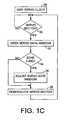
- FIG. 1Cis a flow diagram according to an embodiment of the present invention wherein the servo gate window is adjusted when the head crosses a servo zone boundary.
- FIG. 2Ashows a magnified view of the physical dimensions of the servo sectors across the three servo zones shown in FIG. 1A according to an embodiment of the present invention.
- FIG. 2Billustrates how the servo gate window is adjusted relative to three servo zones according to an embodiment of the present invention.
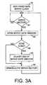
- FIG. 3Ais a flow diagram according to an embodiment wherein a fixed rate servo clock is used to generate the servo gate window, and the end of the servo gate window is adjusted when the head crosses a servo zone boundary.
- FIG. 3Bis a flow diagram according to an embodiment wherein a disk locked servo clock is used to generate the servo gate window, and the interval between servo gate windows is adjusted when the head crosses a servo zone boundary.
- FIG. 4Ashows an embodiment of the present invention wherein the servo gate window is adjusted after detecting the preamble in the servo sector of a new servo zone.
- FIG. 4Bshows an embodiment of the present invention wherein a rate of the servo clock is adjusted after detecting the preamble in the servo sector of a new servo zone.
- FIG. 5shows control circuitry according to an embodiment of the present invention for demodulating the servo sectors and for estimating the current servo zone by processing the servo sector preamble.
- FIG. 1Ashows a disk drive according to an embodiment of the present invention comprising a disk 2 having a plurality of servo sectors 4 0 - 4 N defining a plurality of servo tracks 6 , and a head 8 actuated radially over the disk 2 for generating a read signal 10 .
- FIG. 1Bshows an example format of a servo sector 4 3 including a preamble 12 comprising a periodic pattern for enabling proper gain adjustment and timing synchronization of the read signal 10 .
- the preamble 12comprises a first end and a second end, wherein a servo sync mark 14 is recorded after the second end of the preamble 12 .
- the servo tracks 6form a plurality of servo zones (e.g., servo zones Z 0 , Z 1 , Z 2 ), wherein a servo data rate of the servo sectors in a first servo zone is different than a servo data rate of the servo sectors in a second servo zone.
- the first end of the preambles 12 in the servo sectorsare aligned along a radius of the disk 2 across at least the first servo zone and the second servo zone.
- the sync mark 14 in each servo sector 4comprises a special pattern used to symbol synchronize to a servo data field 16 .
- the servo data field 16stores coarse head positioning information, such as a track address, used to position the head over a target data track during a seek operation.
- Each servo sector 4further comprises groups of servo bursts 18 (e.g., A, B, C and D bursts), which comprise a number of consecutive transitions recorded at precise intervals and offsets with respect to a data track centerline.
- the groups of servo bursts 18provide fine head position information used for centerline tracking while accessing a data track during write/read operations.
- the servo sectors 4 0 - 4 Nmay be written to the disk 2 using any suitable technique, such as with an external servo writer, a media writer, or using the control circuitry 20 within each disk drive to self-servo write the servo sectors 4 0 - 4 N .
- Self servo writingmay involve propagating the servo sectors to servo the head radially over the disk, or by processing seed patterns (e.g., spiral seed patterns) to servo the head radially over the disk.
- a disk-locked clockis typically synchronized to the rotation of the disk (e.g., using a clock track), wherein the disk-locked clock is used to write the servo sectors at the appropriate circumferential location so that the preambles 12 are aligned as shown in FIG. 1A .
- the servo sectors 4 0 - 4 Nmay be stamped onto the surface of the disk using a master stamping disk (i.e., servo pattern printing), or the servo sectors 4 0 - 4 N may be etched onto the surface of the disk so as to have the desired radially aligned preambles 12 as shown in FIG. 1A .
- the control circuitry 20processes the read signal 10 emanating from the head 8 to demodulate the servo sectors 4 0 - 4 N into a position error signal (PES).
- PESposition error signal
- the PESis filtered with a suitable compensation filter to generate a control signal 22 applied to a voice coil motor (VCM) 24 which rotates an actuator arm 26 about a pivot in order to position the head 8 radially over the disk 2 in a direction that reduces the PES.
- VCMvoice coil motor
- FIG. 1Cis a flow diagram executed by the control circuitry 20 according to an embodiment of the present invention wherein a servo clock is generated for servoing the head (step 28 ).
- a servo clockis generated for servoing the head (step 28 ).
- a servo gate windowis opened (step 32 ). If the control circuitry 20 determines that the head 8 has crossed over a servo zone boundary (step 34 ), the servo gate window is adjusted accordingly (step 36 ) and the servo sector demodulated (step 38 ).
- FIG. 2Ashows a magnified view of the physical dimensions of the servo sectors 4 , across the three servo zones in the embodiment of FIG. 1A , wherein the preambles 12 in the servo sectors are aligned along a radius of the disk across the three servo zones Z 0 -Z 2 . Since the data rate increases toward the outer diameter tracks, the physical width of the servo sectors decreases toward the outer diameter servo zones as illustrated by the trapezoidal-shaped servo sectors in FIG. 2A . On the other hand, the physical width of the servo sectors within a zone typically increases towards the outer diameter of the zone.
- FIG. 2Billustrates how the servo gate window is adjusted for each servo zone.
- the servo gate windowis adjusted to account for the change in the data rate of servo sectors.
- the x-axis of FIG. 2Brepresents time in the form of servo clock cycles, and therefore the servo sectors 4 , in each servo zone are shown as having a rectangular shape.
- the servo gate windowis generated using a fixed rate servo clock.
- the T 1 interval(the interval the servo gate window is open) plus the T 2 interval (the interval between servo gate windows) is substantially constant (constant number of servo clock cycles) across the radius of the disk.
- the end of the servo gate windowis adjusted to account for the change in the physical width of the servo sectors. For example, if in FIG. 2B the head transitions from servo zone 0 to servo zone 1 , the T 1 interval is reduced in order to adjust the end of the servo gate window, and the T 2 interval is increased accordingly.
- the servo gate windowis generated using a disk locked servo clock (a servo clock synchronized to the servo data rate).
- a disk locked servo clockWith a disk locked servo clock, the T 1 interval (in servo clock cycles) remains substantially constant across the radius of the disk, whereas the T 2 interval is adjusted. For example, if in FIG. 2B the head transitions from servo zone 0 to servo zone 1 , the T 1 interval remains the same (in servo clock cycles), whereas the T 2 interval is increased to account for the increased recording space between servo sectors.
- FIG. 3Ais a flow diagram according to an embodiment of the present invention wherein a fixed rate servo clock is generated (step 40 ), and when the head approaches a servo sector (step 42 ), the fixed rate servo clock is used to open the servo gate window (step 44 ).
- the headcrosses a servo zone boundary (step 46 )
- the end of the servo gate windowis adjusted (step 48 ) to account for the change in the physical width of the servo sectors, and the servo sector is demodulated (step 50 ).
- FIG. 3Bis a flow diagram according to an embodiment of the present invention wherein a disk locked servo clock is generated (step 52 ), and when the head approaches a servo sector (step 54 ), the disk locked servo clock is used to open the servo gate window (step 56 ).
- the interval between servo gate windowsis adjusted (step 60 ) to account for the increased recording space between servo sectors, and the servo sector is demodulated (step 62 ).
- FIG. 4Aillustrates an embodiment of the present invention wherein when the head crosses from a first servo zone to a second servo zone, the control circuitry 20 adjusts the servo gate window after reading at least part of the preamble in a servo sector in the second servo zone.
- the preamble 12is processed to detect when the head has crossed a servo zone boundary, and therefore when the servo gate window needs adjusting.
- the preamble 12 in the servo sectormay be processed in order to adjust the rate of the servo clock relative to the servo data rate of the second servo zone as illustrated in FIG. 4B .
- FIG. 5shows an example timing circuit comprising a phase locked loop (PLL) for synchronizing a sampling device 64 to the data rate of the read signal 10 .
- An expected sample generator 66generates expected samples 68 corresponding to a target response (e.g., a suitable partial response) relative to the read signal samples 70 .
- a phase detector 72generates a phase error 74 in response to the expected samples 68 and the read signal samples 70 .
- the phase error 74is filtered with a suitable compensation filter 76 to generate a control signal 78 .
- the control signal 78is added 80 to a center frequency 82 to generate a frequency control signal 84 for a voltage controlled oscillator (VCO) 86 .
- VCOvoltage controlled oscillator
- the output 88 of the VCO 86adjusts the frequency of the sampling device 64 until the read signal 10 is sampled synchronously.
- a multiplexer 90selects a nominal center frequency 92 that approximates an average servo data rate out of the plurality of servo zones. Eventually the PLL locks onto the frequency of the preamble 12 that the head is over, and once the servo zone has been identified, the multiplexer 90 selects a center frequency 94 corresponding to the estimated servo zone. Thereafter, when the head 8 crosses a servo zone boundary, the servo zone center frequency 94 is updated after detecting that the head 8 crossed over into a new servo zone.
- the servo zone center frequency 94is generated using an adjustable frequency synthesizer that is programmed to operate at the frequency of the current servo zone.
- the integrator in the compensation filter 76is cleared to account for the new center frequency 82 added to the control signal 78 . Clearing the compensation filter 76 may help the PLL lock faster onto the preamble 12 in the servo sector of the new servo zone.
- the output 88 of the VCO 86may be used as the servo clock (disk locked servo clock) to generate the servo gate window, and in another embodiment, the nominal center frequency 92 (fixed rate servo clock) may be used to generate the servo gate window. In one embodiment, the fixed rate servo clock may be used to generate the servo gate window while the head is crossing a servo zone boundary. Once the disk locked servo clock locks onto the frequency of the new servo zone (e.g., at the end of a seek operation), the servo gate window may be generated using the disk locked servo clock.
- the control signal 78 of the PLLmay be used to estimate a new servo zone.
- the control signal 78represents the offset from the center frequency 94 of the previous servo zone (the difference between the data rate of the previous servo zone and the data rate of the new servo zone).
- the new servo zone center frequency 94is generated as the frequency control signal 84 applied to the VCO 86 after the servo sync mark 14 is detected. In another embodiment, the new servo zone center frequency 94 is generated from a lookup table indexed by the control signal 78 . In one embodiment, the servo zone center frequency 94 is updated after the control circuitry processes the current servo sector of the new servo zone to avoid a timing transient while demodulating the current servo sector.
- timing circuitmay be employed in the embodiments of the present invention, such as an interpolating timing recovery circuit.
- interpolated timing recoverythe read signal is sampled asynchronously and the asynchronous read signal samples are interpolated using an interpolation filter to generate the synchronous read signal samples.
- the interpolating timing recovery circuitgenerates a phase error that is filtered to generate a control signal representing the frequency difference between the data rate of the read signal and the sampling frequency, and therefore provides an estimate of the servo zone.
- Other embodimentsmay be employed to estimate the servo zone, such as by recording a unique servo sync mark 14 in the servo sectors of each servo zone.
- the current servo zonemay be estimated by evaluating which servo sync mark 14 is detected.
- Other embodimentsmay employ suitable frequency detectors for detecting a frequency of the read signal corresponding to each servo zone.
- control circuitrymay be implemented within a read channel integrated circuit, or in a component separate from the read channel, such as a disk controller, or certain steps described above may be performed by a read channel and others by a disk controller.
- the read channel and disk controllerare implemented as separate integrated circuits, and in an alternative embodiment they are fabricated into a single integrated circuit or system on a chip (SOC).
- the control circuitrymay include a suitable preamp circuit implemented as a separate integrated circuit, integrated into the read channel or disk controller circuit, or integrated into an SOC.
- control circuitrycomprises a microprocessor executing instructions, the instructions being operable to cause the microprocessor to perform the steps of the flow diagrams described herein.
- the instructionsmay be stored in any computer-readable medium. In one embodiment, they may be stored on a non-volatile semiconductor memory external to the microprocessor, or integrated with the microprocessor in a SOC. In another embodiment, the instructions are stored on the disk and read into a volatile semiconductor memory when the disk drive is powered on. In yet another embodiment, the control circuitry comprises suitable logic circuitry, such as state machine circuitry.
Landscapes
- Engineering & Computer Science (AREA)
- Signal Processing (AREA)
- Moving Of The Head To Find And Align With The Track (AREA)
- Signal Processing For Digital Recording And Reproducing (AREA)
Abstract
Description
Claims (8)
Priority Applications (1)
| Application Number | Priority Date | Filing Date | Title |
|---|---|---|---|
| US12/335,291US8116023B1 (en) | 2008-12-15 | 2008-12-15 | Disk drive comprising preamble aligned zoned servo sectors |
Applications Claiming Priority (1)
| Application Number | Priority Date | Filing Date | Title |
|---|---|---|---|
| US12/335,291US8116023B1 (en) | 2008-12-15 | 2008-12-15 | Disk drive comprising preamble aligned zoned servo sectors |
Publications (1)
| Publication Number | Publication Date |
|---|---|
| US8116023B1true US8116023B1 (en) | 2012-02-14 |
Family
ID=45561502
Family Applications (1)
| Application Number | Title | Priority Date | Filing Date |
|---|---|---|---|
| US12/335,291Expired - Fee RelatedUS8116023B1 (en) | 2008-12-15 | 2008-12-15 | Disk drive comprising preamble aligned zoned servo sectors |
Country Status (1)
| Country | Link |
|---|---|
| US (1) | US8116023B1 (en) |
Cited By (110)
| Publication number | Priority date | Publication date | Assignee | Title |
|---|---|---|---|---|
| US8576506B1 (en) | 2012-06-21 | 2013-11-05 | Western Digital Technologies, Inc. | Disk drive estimating reader/writer gap across servo zones |
| US8724245B1 (en) | 2012-06-21 | 2014-05-13 | Western Digital Technologies, Inc. | Disk drive employing overlapping servo zones to facilitate servo zone crossing |
| US8743504B1 (en) | 2012-07-25 | 2014-06-03 | Western Digital Technologies, Inc. | Servoing on zoned concentric servo sectors of a first disk surface to write a spiral servo track to a second disk surface |
| US8780477B1 (en) | 2012-06-21 | 2014-07-15 | Western Digital Technologies, Inc. | Disk drive adjusting servo timing to compensate for transient when crossing a servo zone boundary |
| US8824081B1 (en) | 2012-03-13 | 2014-09-02 | Western Digital Technologies, Inc. | Disk drive employing radially coherent reference pattern for servo burst demodulation and fly height measurement |
| US8830617B1 (en) | 2013-05-30 | 2014-09-09 | Western Digital Technologies, Inc. | Disk drive adjusting state estimator to compensate for unreliable servo data |
| US8879191B1 (en) | 2012-11-14 | 2014-11-04 | Western Digital Technologies, Inc. | Disk drive modifying rotational position optimization algorithm to achieve target performance for limited stroke |
| US8891191B1 (en) | 2014-05-06 | 2014-11-18 | Western Digital Technologies, Inc. | Data storage device initializing read signal gain to detect servo seed pattern |
| US8891194B1 (en) | 2013-05-14 | 2014-11-18 | Western Digital Technologies, Inc. | Disk drive iteratively adapting correction value that compensates for non-linearity of head |
| US8896957B1 (en) | 2013-05-10 | 2014-11-25 | Western Digital Technologies, Inc. | Disk drive performing spiral scan of disk surface to detect residual data |
| US8902538B1 (en) | 2013-03-29 | 2014-12-02 | Western Digital Technologies, Inc. | Disk drive detecting crack in microactuator |
| US8902539B1 (en) | 2014-05-13 | 2014-12-02 | Western Digital Technologies, Inc. | Data storage device reducing seek power consumption |
| US8913342B1 (en) | 2014-03-21 | 2014-12-16 | Western Digital Technologies, Inc. | Data storage device adjusting range of microactuator digital-to-analog converter based on operating temperature |
| US8917474B1 (en) | 2011-08-08 | 2014-12-23 | Western Digital Technologies, Inc. | Disk drive calibrating a velocity profile prior to writing a spiral track |
| US8917475B1 (en) | 2013-12-20 | 2014-12-23 | Western Digital Technologies, Inc. | Disk drive generating a disk locked clock using radial dependent timing feed-forward compensation |
| US8922938B1 (en) | 2012-11-02 | 2014-12-30 | Western Digital Technologies, Inc. | Disk drive filtering disturbance signal and error signal for adaptive feed-forward compensation |
| US8922937B1 (en) | 2012-04-19 | 2014-12-30 | Western Digital Technologies, Inc. | Disk drive evaluating multiple vibration sensor outputs to enable write-protection |
| US8922940B1 (en) | 2014-05-27 | 2014-12-30 | Western Digital Technologies, Inc. | Data storage device reducing spindle motor voltage boost during power failure |
| US8922931B1 (en) | 2013-05-13 | 2014-12-30 | Western Digital Technologies, Inc. | Disk drive releasing variable amount of buffered write data based on sliding window of predicted servo quality |
| US8929022B1 (en) | 2012-12-19 | 2015-01-06 | Western Digital Technologies, Inc. | Disk drive detecting microactuator degradation by evaluating frequency component of servo signal |
| US8929021B1 (en) | 2012-03-27 | 2015-01-06 | Western Digital Technologies, Inc. | Disk drive servo writing from spiral tracks using radial dependent timing feed-forward compensation |
| US8934186B1 (en) | 2014-03-26 | 2015-01-13 | Western Digital Technologies, Inc. | Data storage device estimating servo zone to reduce size of track address |
| US8937784B1 (en) | 2012-08-01 | 2015-01-20 | Western Digital Technologies, Inc. | Disk drive employing feed-forward compensation and phase shift compensation during seek settling |
| US8941945B1 (en) | 2014-06-06 | 2015-01-27 | Western Digital Technologies, Inc. | Data storage device servoing heads based on virtual servo tracks |
| US8941939B1 (en) | 2013-10-24 | 2015-01-27 | Western Digital Technologies, Inc. | Disk drive using VCM BEMF feed-forward compensation to write servo data to a disk |
| US8947819B1 (en) | 2012-08-28 | 2015-02-03 | Western Digital Technologies, Inc. | Disk drive implementing hysteresis for primary shock detector based on a more sensitive secondary shock detector |
| US8953278B1 (en) | 2011-11-16 | 2015-02-10 | Western Digital Technologies, Inc. | Disk drive selecting disturbance signal for feed-forward compensation |
| US8953271B1 (en) | 2013-05-13 | 2015-02-10 | Western Digital Technologies, Inc. | Disk drive compensating for repeatable run out selectively per zone |
| US8958169B1 (en) | 2014-06-11 | 2015-02-17 | Western Digital Technologies, Inc. | Data storage device re-qualifying state estimator while decelerating head |
| US8970979B1 (en) | 2013-12-18 | 2015-03-03 | Western Digital Technologies, Inc. | Disk drive determining frequency response of actuator near servo sample frequency |
| US8982490B1 (en) | 2014-04-24 | 2015-03-17 | Western Digital Technologies, Inc. | Data storage device reading first spiral track while simultaneously writing second spiral track |
| US8982501B1 (en) | 2014-09-22 | 2015-03-17 | Western Digital Technologies, Inc. | Data storage device compensating for repeatable disturbance when commutating a spindle motor |
| US8995082B1 (en) | 2011-06-03 | 2015-03-31 | Western Digital Technologies, Inc. | Reducing acoustic noise in a disk drive when exiting idle mode |
| US8995075B1 (en) | 2012-06-21 | 2015-03-31 | Western Digital Technologies, Inc. | Disk drive adjusting estimated servo state to compensate for transient when crossing a servo zone boundary |
| US9001454B1 (en) | 2013-04-12 | 2015-04-07 | Western Digital Technologies, Inc. | Disk drive adjusting phase of adaptive feed-forward controller when reconfiguring servo loop |
| US9007714B1 (en) | 2014-07-18 | 2015-04-14 | Western Digital Technologies Inc. | Data storage device comprising slew rate anti-windup compensation for microactuator |
| US9013824B1 (en) | 2014-06-04 | 2015-04-21 | Western Digital Technologies, Inc. | Data storage device comprising dual read sensors and dual servo channels to improve servo demodulation |
| US9013825B1 (en) | 2014-03-24 | 2015-04-21 | Western Digital Technologies, Inc. | Electronic system with vibration management mechanism and method of operation thereof |
| US9026728B1 (en) | 2013-06-06 | 2015-05-05 | Western Digital Technologies, Inc. | Disk drive applying feed-forward compensation when writing consecutive data tracks |
| US9025269B1 (en) | 2014-01-02 | 2015-05-05 | Western Digital Technologies, Inc. | Disk drive compensating for cycle slip of disk locked clock when reading mini-wedge |
| US9047932B1 (en) | 2014-03-21 | 2015-06-02 | Western Digital Technologies, Inc. | Data storage device adjusting a power loss threshold based on samples of supply voltage |
| US9047919B1 (en) | 2013-03-12 | 2015-06-02 | Western Digitial Technologies, Inc. | Disk drive initializing servo read channel by reading data preceding servo preamble during access operation |
| US9047901B1 (en) | 2013-05-28 | 2015-06-02 | Western Digital Technologies, Inc. | Disk drive measuring spiral track error by measuring a slope of a spiral track across a disk radius |
| US9053727B1 (en) | 2014-06-02 | 2015-06-09 | Western Digital Technologies, Inc. | Disk drive opening spiral crossing window based on DC and AC spiral track error |
| US9053726B1 (en) | 2014-01-29 | 2015-06-09 | Western Digital Technologies, Inc. | Data storage device on-line adapting disturbance observer filter |
| US9053712B1 (en) | 2014-05-07 | 2015-06-09 | Western Digital Technologies, Inc. | Data storage device reading servo sector while writing data sector |
| US9058826B1 (en) | 2014-02-13 | 2015-06-16 | Western Digital Technologies, Inc. | Data storage device detecting free fall condition from disk speed variations |
| US9058834B1 (en) | 2013-11-08 | 2015-06-16 | Western Digital Technologies, Inc. | Power architecture for low power modes in storage devices |
| US9058827B1 (en) | 2013-06-25 | 2015-06-16 | Western Digitial Technologies, Inc. | Disk drive optimizing filters based on sensor signal and disturbance signal for adaptive feed-forward compensation |
| US9064537B1 (en) | 2013-09-13 | 2015-06-23 | Western Digital Technologies, Inc. | Disk drive measuring radial offset between heads by detecting a difference between ramp contact |
| US9070411B1 (en)* | 2013-07-04 | 2015-06-30 | Seagate Technology Llc | Writable servo overlap zones |
| US9076473B1 (en) | 2014-08-12 | 2015-07-07 | Western Digital Technologies, Inc. | Data storage device detecting fly height instability of head during load operation based on microactuator response |
| US9076472B1 (en) | 2014-08-21 | 2015-07-07 | Western Digital (Fremont), Llc | Apparatus enabling writing servo data when disk reaches target rotation speed |
| US9076490B1 (en) | 2012-12-12 | 2015-07-07 | Western Digital Technologies, Inc. | Disk drive writing radial offset spiral servo tracks by reading spiral seed tracks |
| US9076471B1 (en) | 2013-07-31 | 2015-07-07 | Western Digital Technologies, Inc. | Fall detection scheme using FFS |
| US9093105B2 (en) | 2011-12-09 | 2015-07-28 | Western Digital Technologies, Inc. | Disk drive charging capacitor using motor supply voltage during power failure |
| US9099147B1 (en) | 2014-09-22 | 2015-08-04 | Western Digital Technologies, Inc. | Data storage device commutating a spindle motor using closed-loop rotation phase alignment |
| US9111575B1 (en) | 2014-10-23 | 2015-08-18 | Western Digital Technologies, Inc. | Data storage device employing adaptive feed-forward control in timing loop to compensate for vibration |
| US9129630B1 (en) | 2014-12-16 | 2015-09-08 | Western Digital Technologies, Inc. | Data storage device employing full servo sectors on first disk surface and mini servo sectors on second disk surface |
| US9141177B1 (en) | 2014-03-21 | 2015-09-22 | Western Digital Technologies, Inc. | Data storage device employing glitch compensation for power loss detection |
| US9142235B1 (en) | 2009-10-27 | 2015-09-22 | Western Digital Technologies, Inc. | Disk drive characterizing microactuator by injecting sinusoidal disturbance and evaluating feed-forward compensation values |
| US9142249B1 (en) | 2013-12-06 | 2015-09-22 | Western Digital Technologies, Inc. | Disk drive using timing loop control signal for vibration compensation in servo loop |
| US9142225B1 (en) | 2014-03-21 | 2015-09-22 | Western Digital Technologies, Inc. | Electronic system with actuator control mechanism and method of operation thereof |
| US9147418B1 (en) | 2013-06-20 | 2015-09-29 | Western Digital Technologies, Inc. | Disk drive compensating for microactuator gain variations |
| US9147428B1 (en) | 2013-04-24 | 2015-09-29 | Western Digital Technologies, Inc. | Disk drive with improved spin-up control |
| US9153283B1 (en) | 2014-09-30 | 2015-10-06 | Western Digital Technologies, Inc. | Data storage device compensating for hysteretic response of microactuator |
| US9165583B1 (en) | 2014-10-29 | 2015-10-20 | Western Digital Technologies, Inc. | Data storage device adjusting seek profile based on seek length when ending track is near ramp |
| US9171567B1 (en) | 2014-05-27 | 2015-10-27 | Western Digital Technologies, Inc. | Data storage device employing sliding mode control of spindle motor |
| US9171568B1 (en) | 2014-06-25 | 2015-10-27 | Western Digital Technologies, Inc. | Data storage device periodically re-initializing spindle motor commutation sequence based on timing data |
| US9208808B1 (en) | 2014-04-22 | 2015-12-08 | Western Digital Technologies, Inc. | Electronic system with unload management mechanism and method of operation thereof |
| US9208810B1 (en) | 2014-04-24 | 2015-12-08 | Western Digital Technologies, Inc. | Data storage device attenuating interference from first spiral track when reading second spiral track |
| US9208815B1 (en) | 2014-10-09 | 2015-12-08 | Western Digital Technologies, Inc. | Data storage device dynamically reducing coast velocity during seek to reduce power consumption |
| US9214175B1 (en) | 2015-03-16 | 2015-12-15 | Western Digital Technologies, Inc. | Data storage device configuring a gain of a servo control system for actuating a head over a disk |
| US9230593B1 (en) | 2014-12-23 | 2016-01-05 | Western Digital Technologies, Inc. | Data storage device optimizing spindle motor power when transitioning into a power failure mode |
| US9230592B1 (en) | 2014-12-23 | 2016-01-05 | Western Digital Technologies, Inc. | Electronic system with a method of motor spindle bandwidth estimation and calibration thereof |
| US9245577B1 (en) | 2015-03-26 | 2016-01-26 | Western Digital Technologies, Inc. | Data storage device comprising spindle motor current sensing with supply voltage noise attenuation |
| US9245560B1 (en) | 2015-03-09 | 2016-01-26 | Western Digital Technologies, Inc. | Data storage device measuring reader/writer offset by reading spiral track and concentric servo sectors |
| US9245540B1 (en) | 2014-10-29 | 2016-01-26 | Western Digital Technologies, Inc. | Voice coil motor temperature sensing circuit to reduce catastrophic failure due to voice coil motor coil shorting to ground |
| US9251823B1 (en) | 2014-12-10 | 2016-02-02 | Western Digital Technologies, Inc. | Data storage device delaying seek operation to avoid thermal asperities |
| US9269386B1 (en) | 2014-01-29 | 2016-02-23 | Western Digital Technologies, Inc. | Data storage device on-line adapting disturbance observer filter |
| US9286927B1 (en) | 2014-12-16 | 2016-03-15 | Western Digital Technologies, Inc. | Data storage device demodulating servo burst by computing slope of intermediate integration points |
| US9286925B1 (en) | 2015-03-26 | 2016-03-15 | Western Digital Technologies, Inc. | Data storage device writing multiple burst correction values at the same radial location |
| US9343102B1 (en) | 2015-03-25 | 2016-05-17 | Western Digital Technologies, Inc. | Data storage device employing a phase offset to generate power from a spindle motor during a power failure |
| US9343094B1 (en) | 2015-03-26 | 2016-05-17 | Western Digital Technologies, Inc. | Data storage device filtering burst correction values before downsampling the burst correction values |
| US9349401B1 (en) | 2014-07-24 | 2016-05-24 | Western Digital Technologies, Inc. | Electronic system with media scan mechanism and method of operation thereof |
| US9350278B1 (en) | 2014-06-13 | 2016-05-24 | Western Digital Technologies, Inc. | Circuit technique to integrate voice coil motor support elements |
| US9355667B1 (en) | 2014-11-11 | 2016-05-31 | Western Digital Technologies, Inc. | Data storage device saving absolute position at each servo wedge for previous write operations |
| US9355676B1 (en) | 2015-03-25 | 2016-05-31 | Western Digital Technologies, Inc. | Data storage device controlling amplitude and phase of driving voltage to generate power from a spindle motor |
| US9361939B1 (en) | 2014-03-10 | 2016-06-07 | Western Digital Technologies, Inc. | Data storage device characterizing geometry of magnetic transitions |
| US9396751B1 (en) | 2015-06-26 | 2016-07-19 | Western Digital Technologies, Inc. | Data storage device compensating for fabrication tolerances when measuring spindle motor current |
| US9407015B1 (en) | 2014-12-29 | 2016-08-02 | Western Digital Technologies, Inc. | Automatic power disconnect device |
| US9418689B2 (en) | 2014-10-09 | 2016-08-16 | Western Digital Technologies, Inc. | Data storage device generating an operating seek time profile as a function of a base seek time profile |
| US9424868B1 (en) | 2015-05-12 | 2016-08-23 | Western Digital Technologies, Inc. | Data storage device employing spindle motor driving profile during seek to improve power performance |
| US9424871B1 (en) | 2012-09-13 | 2016-08-23 | Western Digital Technologies, Inc. | Disk drive correcting an error in a detected gray code |
| US9437237B1 (en) | 2015-02-20 | 2016-09-06 | Western Digital Technologies, Inc. | Method to detect power loss through data storage device spindle speed |
| US9437231B1 (en) | 2015-09-25 | 2016-09-06 | Western Digital Technologies, Inc. | Data storage device concurrently controlling and sensing a secondary actuator for actuating a head over a disk |
| US9454212B1 (en) | 2014-12-08 | 2016-09-27 | Western Digital Technologies, Inc. | Wakeup detector |
| US9471072B1 (en) | 2013-11-14 | 2016-10-18 | Western Digital Technologies, Inc | Self-adaptive voltage scaling |
| US9484733B1 (en) | 2013-09-11 | 2016-11-01 | Western Digital Technologies, Inc. | Power control module for data storage device |
| US9542966B1 (en) | 2015-07-09 | 2017-01-10 | Western Digital Technologies, Inc. | Data storage devices and methods with frequency-shaped sliding mode control |
| US9564162B1 (en) | 2015-12-28 | 2017-02-07 | Western Digital Technologies, Inc. | Data storage device measuring resonant frequency of a shock sensor by applying differential excitation and measuring oscillation |
| US9581978B1 (en) | 2014-12-17 | 2017-02-28 | Western Digital Technologies, Inc. | Electronic system with servo management mechanism and method of operation thereof |
| US9620160B1 (en) | 2015-12-28 | 2017-04-11 | Western Digital Technologies, Inc. | Data storage device measuring resonant frequency of a shock sensor by inserting the shock sensor into an oscillator circuit |
| US9823294B1 (en) | 2013-10-29 | 2017-11-21 | Western Digital Technologies, Inc. | Negative voltage testing methodology and tester |
| US9886285B2 (en) | 2015-03-31 | 2018-02-06 | Western Digital Technologies, Inc. | Communication interface initialization |
| US9899834B1 (en) | 2015-11-18 | 2018-02-20 | Western Digital Technologies, Inc. | Power control module using protection circuit for regulating backup voltage to power load during power fault |
| US9905256B1 (en)* | 2017-03-16 | 2018-02-27 | Kabushiki Kaisha Toshiba | Magnetic disc apparatus |
| US9959204B1 (en) | 2015-03-09 | 2018-05-01 | Western Digital Technologies, Inc. | Tracking sequential ranges of non-ordered data |
| US10748569B1 (en)* | 2019-03-19 | 2020-08-18 | Kabushiki Kaisha Toshiba | Magnetic disk device and method for demodulating servo demodulation position |
| US20200286517A1 (en)* | 2019-03-08 | 2020-09-10 | Kabushiki Kaisha Toshiba | Magnetic disk device, writing method of servo sector, and method of correcting servo demodulation position |
Citations (13)
| Publication number | Priority date | Publication date | Assignee | Title |
|---|---|---|---|---|
| US5384671A (en)* | 1993-12-23 | 1995-01-24 | Quantum Corporation | PRML sampled data channel synchronous servo detector |
| US5418659A (en) | 1993-12-23 | 1995-05-23 | National Semiconductor Corporation | Reliable time-domain demarcation of split formats in embedded-servo, zoned-data recording disk drives |
| US5796535A (en) | 1995-05-12 | 1998-08-18 | Cirrus Logic, Inc. | Sampled amplitude read channel employing a user data frequency synthesizer and a servo data frequency synthesizer |
| US5956196A (en) | 1993-04-09 | 1999-09-21 | Western Digital Corporation | Disk drive employing dynamically reconfigured read channel to process a read signal at two different frequencies |
| US6084738A (en) | 1997-08-15 | 2000-07-04 | Seagate Technology, Inc. | Writing servo information to a disc drive at a constant density |
| US6118604A (en) | 1997-08-15 | 2000-09-12 | Seagate Technology, Inc. | Constant density servo information in a disc drive |
| US6178056B1 (en) | 1997-03-11 | 2001-01-23 | Western Digital Corporation | Disk drive employing state variable trap registers for providing stored servo and user data state variables to sampled-data channel |
| US6388829B1 (en) | 1999-07-30 | 2002-05-14 | Western Digital Technologies, Inc. | High servo sampling disk drive with minimum overhead |
| US6515813B2 (en)* | 2000-01-17 | 2003-02-04 | International Business Machines Corporation | Method for controlling servo information detection timing and rotational speed of disk, and disk drive |
| US7012773B2 (en) | 2002-04-18 | 2006-03-14 | Fujitsu Limited | Disk device and disk medium, in which a plurality of servo cylinders formed concentrically from the inner diametrical portion to the outer diametrical portion of at least one disk are divided into predetermined areas |
| US7054083B2 (en) | 2003-07-16 | 2006-05-30 | Matsushita Electric Industrial Co., Ltd. | Systems for searching for SAM patterns at multiple nominal frequencies |
| US20070064325A1 (en) | 2005-09-21 | 2007-03-22 | Seagate Technology Llc | Data storage medium with optimized servo format |
| US7212364B1 (en)* | 2004-01-31 | 2007-05-01 | Western Digital Technologies, Inc. | Servo writing a disk drive by synchronizing a servo write clock in response to a sync mark reliability metric |
- 2008
- 2008-12-15USUS12/335,291patent/US8116023B1/ennot_activeExpired - Fee Related
Patent Citations (17)
| Publication number | Priority date | Publication date | Assignee | Title |
|---|---|---|---|---|
| US5956196A (en) | 1993-04-09 | 1999-09-21 | Western Digital Corporation | Disk drive employing dynamically reconfigured read channel to process a read signal at two different frequencies |
| US5418659A (en) | 1993-12-23 | 1995-05-23 | National Semiconductor Corporation | Reliable time-domain demarcation of split formats in embedded-servo, zoned-data recording disk drives |
| US5384671A (en)* | 1993-12-23 | 1995-01-24 | Quantum Corporation | PRML sampled data channel synchronous servo detector |
| US5796535A (en) | 1995-05-12 | 1998-08-18 | Cirrus Logic, Inc. | Sampled amplitude read channel employing a user data frequency synthesizer and a servo data frequency synthesizer |
| US6441981B1 (en) | 1997-03-11 | 2002-08-27 | Western Digital Technologies, Inc. | Disk drive including a recording surface employing servo zones recorded at a channel frequency different from data zones |
| US6178056B1 (en) | 1997-03-11 | 2001-01-23 | Western Digital Corporation | Disk drive employing state variable trap registers for providing stored servo and user data state variables to sampled-data channel |
| US6262857B1 (en) | 1997-03-11 | 2001-07-17 | Western Digital Corporation | Disk drive including a recording surface employing servo zones with banded data zones |
| US6411452B1 (en) | 1997-03-11 | 2002-06-25 | Western Digital Technologies, Inc. | Disk drive employing read error tolerant sync mark detection |
| US6084738A (en) | 1997-08-15 | 2000-07-04 | Seagate Technology, Inc. | Writing servo information to a disc drive at a constant density |
| US6118604A (en) | 1997-08-15 | 2000-09-12 | Seagate Technology, Inc. | Constant density servo information in a disc drive |
| US6388829B1 (en) | 1999-07-30 | 2002-05-14 | Western Digital Technologies, Inc. | High servo sampling disk drive with minimum overhead |
| US6515813B2 (en)* | 2000-01-17 | 2003-02-04 | International Business Machines Corporation | Method for controlling servo information detection timing and rotational speed of disk, and disk drive |
| US7012773B2 (en) | 2002-04-18 | 2006-03-14 | Fujitsu Limited | Disk device and disk medium, in which a plurality of servo cylinders formed concentrically from the inner diametrical portion to the outer diametrical portion of at least one disk are divided into predetermined areas |
| US7054083B2 (en) | 2003-07-16 | 2006-05-30 | Matsushita Electric Industrial Co., Ltd. | Systems for searching for SAM patterns at multiple nominal frequencies |
| US7212364B1 (en)* | 2004-01-31 | 2007-05-01 | Western Digital Technologies, Inc. | Servo writing a disk drive by synchronizing a servo write clock in response to a sync mark reliability metric |
| US20070064325A1 (en) | 2005-09-21 | 2007-03-22 | Seagate Technology Llc | Data storage medium with optimized servo format |
| US7405893B2 (en)* | 2005-09-21 | 2008-07-29 | Seagate Technology Llc | Data storage medium with optimized servo format |
Cited By (118)
| Publication number | Priority date | Publication date | Assignee | Title |
|---|---|---|---|---|
| US9142235B1 (en) | 2009-10-27 | 2015-09-22 | Western Digital Technologies, Inc. | Disk drive characterizing microactuator by injecting sinusoidal disturbance and evaluating feed-forward compensation values |
| US8995082B1 (en) | 2011-06-03 | 2015-03-31 | Western Digital Technologies, Inc. | Reducing acoustic noise in a disk drive when exiting idle mode |
| US8917474B1 (en) | 2011-08-08 | 2014-12-23 | Western Digital Technologies, Inc. | Disk drive calibrating a velocity profile prior to writing a spiral track |
| US8953278B1 (en) | 2011-11-16 | 2015-02-10 | Western Digital Technologies, Inc. | Disk drive selecting disturbance signal for feed-forward compensation |
| US9390749B2 (en) | 2011-12-09 | 2016-07-12 | Western Digital Technologies, Inc. | Power failure management in disk drives |
| US9093105B2 (en) | 2011-12-09 | 2015-07-28 | Western Digital Technologies, Inc. | Disk drive charging capacitor using motor supply voltage during power failure |
| US8824081B1 (en) | 2012-03-13 | 2014-09-02 | Western Digital Technologies, Inc. | Disk drive employing radially coherent reference pattern for servo burst demodulation and fly height measurement |
| US8929021B1 (en) | 2012-03-27 | 2015-01-06 | Western Digital Technologies, Inc. | Disk drive servo writing from spiral tracks using radial dependent timing feed-forward compensation |
| US8934191B1 (en) | 2012-03-27 | 2015-01-13 | Western Digital Technologies, Inc. | Disk drive generating a disk locked clock using radial dependent timing feed-forward compensation |
| US8922937B1 (en) | 2012-04-19 | 2014-12-30 | Western Digital Technologies, Inc. | Disk drive evaluating multiple vibration sensor outputs to enable write-protection |
| US8995075B1 (en) | 2012-06-21 | 2015-03-31 | Western Digital Technologies, Inc. | Disk drive adjusting estimated servo state to compensate for transient when crossing a servo zone boundary |
| US8724245B1 (en) | 2012-06-21 | 2014-05-13 | Western Digital Technologies, Inc. | Disk drive employing overlapping servo zones to facilitate servo zone crossing |
| US8780477B1 (en) | 2012-06-21 | 2014-07-15 | Western Digital Technologies, Inc. | Disk drive adjusting servo timing to compensate for transient when crossing a servo zone boundary |
| US9454989B1 (en) | 2012-06-21 | 2016-09-27 | Western Digital Technologies, Inc. | Disk drive adjusting estimated servo state to compensate for transient when crossing a servo zone boundary |
| US8576506B1 (en) | 2012-06-21 | 2013-11-05 | Western Digital Technologies, Inc. | Disk drive estimating reader/writer gap across servo zones |
| US8743504B1 (en) | 2012-07-25 | 2014-06-03 | Western Digital Technologies, Inc. | Servoing on zoned concentric servo sectors of a first disk surface to write a spiral servo track to a second disk surface |
| US8937784B1 (en) | 2012-08-01 | 2015-01-20 | Western Digital Technologies, Inc. | Disk drive employing feed-forward compensation and phase shift compensation during seek settling |
| US8947819B1 (en) | 2012-08-28 | 2015-02-03 | Western Digital Technologies, Inc. | Disk drive implementing hysteresis for primary shock detector based on a more sensitive secondary shock detector |
| US9424871B1 (en) | 2012-09-13 | 2016-08-23 | Western Digital Technologies, Inc. | Disk drive correcting an error in a detected gray code |
| US8922938B1 (en) | 2012-11-02 | 2014-12-30 | Western Digital Technologies, Inc. | Disk drive filtering disturbance signal and error signal for adaptive feed-forward compensation |
| US8879191B1 (en) | 2012-11-14 | 2014-11-04 | Western Digital Technologies, Inc. | Disk drive modifying rotational position optimization algorithm to achieve target performance for limited stroke |
| US9076490B1 (en) | 2012-12-12 | 2015-07-07 | Western Digital Technologies, Inc. | Disk drive writing radial offset spiral servo tracks by reading spiral seed tracks |
| US8929022B1 (en) | 2012-12-19 | 2015-01-06 | Western Digital Technologies, Inc. | Disk drive detecting microactuator degradation by evaluating frequency component of servo signal |
| US9047919B1 (en) | 2013-03-12 | 2015-06-02 | Western Digitial Technologies, Inc. | Disk drive initializing servo read channel by reading data preceding servo preamble during access operation |
| US8902538B1 (en) | 2013-03-29 | 2014-12-02 | Western Digital Technologies, Inc. | Disk drive detecting crack in microactuator |
| US9001454B1 (en) | 2013-04-12 | 2015-04-07 | Western Digital Technologies, Inc. | Disk drive adjusting phase of adaptive feed-forward controller when reconfiguring servo loop |
| US9147428B1 (en) | 2013-04-24 | 2015-09-29 | Western Digital Technologies, Inc. | Disk drive with improved spin-up control |
| US8896957B1 (en) | 2013-05-10 | 2014-11-25 | Western Digital Technologies, Inc. | Disk drive performing spiral scan of disk surface to detect residual data |
| US8922931B1 (en) | 2013-05-13 | 2014-12-30 | Western Digital Technologies, Inc. | Disk drive releasing variable amount of buffered write data based on sliding window of predicted servo quality |
| US8953271B1 (en) | 2013-05-13 | 2015-02-10 | Western Digital Technologies, Inc. | Disk drive compensating for repeatable run out selectively per zone |
| US8891194B1 (en) | 2013-05-14 | 2014-11-18 | Western Digital Technologies, Inc. | Disk drive iteratively adapting correction value that compensates for non-linearity of head |
| US9047901B1 (en) | 2013-05-28 | 2015-06-02 | Western Digital Technologies, Inc. | Disk drive measuring spiral track error by measuring a slope of a spiral track across a disk radius |
| US8830617B1 (en) | 2013-05-30 | 2014-09-09 | Western Digital Technologies, Inc. | Disk drive adjusting state estimator to compensate for unreliable servo data |
| US9026728B1 (en) | 2013-06-06 | 2015-05-05 | Western Digital Technologies, Inc. | Disk drive applying feed-forward compensation when writing consecutive data tracks |
| US9147418B1 (en) | 2013-06-20 | 2015-09-29 | Western Digital Technologies, Inc. | Disk drive compensating for microactuator gain variations |
| US9058827B1 (en) | 2013-06-25 | 2015-06-16 | Western Digitial Technologies, Inc. | Disk drive optimizing filters based on sensor signal and disturbance signal for adaptive feed-forward compensation |
| US9070411B1 (en)* | 2013-07-04 | 2015-06-30 | Seagate Technology Llc | Writable servo overlap zones |
| US9076471B1 (en) | 2013-07-31 | 2015-07-07 | Western Digital Technologies, Inc. | Fall detection scheme using FFS |
| US9484733B1 (en) | 2013-09-11 | 2016-11-01 | Western Digital Technologies, Inc. | Power control module for data storage device |
| US9064537B1 (en) | 2013-09-13 | 2015-06-23 | Western Digital Technologies, Inc. | Disk drive measuring radial offset between heads by detecting a difference between ramp contact |
| US8941939B1 (en) | 2013-10-24 | 2015-01-27 | Western Digital Technologies, Inc. | Disk drive using VCM BEMF feed-forward compensation to write servo data to a disk |
| US9823294B1 (en) | 2013-10-29 | 2017-11-21 | Western Digital Technologies, Inc. | Negative voltage testing methodology and tester |
| US9058834B1 (en) | 2013-11-08 | 2015-06-16 | Western Digital Technologies, Inc. | Power architecture for low power modes in storage devices |
| US9471072B1 (en) | 2013-11-14 | 2016-10-18 | Western Digital Technologies, Inc | Self-adaptive voltage scaling |
| US9142249B1 (en) | 2013-12-06 | 2015-09-22 | Western Digital Technologies, Inc. | Disk drive using timing loop control signal for vibration compensation in servo loop |
| US8970979B1 (en) | 2013-12-18 | 2015-03-03 | Western Digital Technologies, Inc. | Disk drive determining frequency response of actuator near servo sample frequency |
| US8917475B1 (en) | 2013-12-20 | 2014-12-23 | Western Digital Technologies, Inc. | Disk drive generating a disk locked clock using radial dependent timing feed-forward compensation |
| US9025269B1 (en) | 2014-01-02 | 2015-05-05 | Western Digital Technologies, Inc. | Disk drive compensating for cycle slip of disk locked clock when reading mini-wedge |
| US9053726B1 (en) | 2014-01-29 | 2015-06-09 | Western Digital Technologies, Inc. | Data storage device on-line adapting disturbance observer filter |
| US9269386B1 (en) | 2014-01-29 | 2016-02-23 | Western Digital Technologies, Inc. | Data storage device on-line adapting disturbance observer filter |
| US9058826B1 (en) | 2014-02-13 | 2015-06-16 | Western Digital Technologies, Inc. | Data storage device detecting free fall condition from disk speed variations |
| US9361939B1 (en) | 2014-03-10 | 2016-06-07 | Western Digital Technologies, Inc. | Data storage device characterizing geometry of magnetic transitions |
| US9142225B1 (en) | 2014-03-21 | 2015-09-22 | Western Digital Technologies, Inc. | Electronic system with actuator control mechanism and method of operation thereof |
| US9047932B1 (en) | 2014-03-21 | 2015-06-02 | Western Digital Technologies, Inc. | Data storage device adjusting a power loss threshold based on samples of supply voltage |
| US8913342B1 (en) | 2014-03-21 | 2014-12-16 | Western Digital Technologies, Inc. | Data storage device adjusting range of microactuator digital-to-analog converter based on operating temperature |
| US9141177B1 (en) | 2014-03-21 | 2015-09-22 | Western Digital Technologies, Inc. | Data storage device employing glitch compensation for power loss detection |
| US9013825B1 (en) | 2014-03-24 | 2015-04-21 | Western Digital Technologies, Inc. | Electronic system with vibration management mechanism and method of operation thereof |
| US8934186B1 (en) | 2014-03-26 | 2015-01-13 | Western Digital Technologies, Inc. | Data storage device estimating servo zone to reduce size of track address |
| US9208808B1 (en) | 2014-04-22 | 2015-12-08 | Western Digital Technologies, Inc. | Electronic system with unload management mechanism and method of operation thereof |
| US8982490B1 (en) | 2014-04-24 | 2015-03-17 | Western Digital Technologies, Inc. | Data storage device reading first spiral track while simultaneously writing second spiral track |
| US9208810B1 (en) | 2014-04-24 | 2015-12-08 | Western Digital Technologies, Inc. | Data storage device attenuating interference from first spiral track when reading second spiral track |
| US8891191B1 (en) | 2014-05-06 | 2014-11-18 | Western Digital Technologies, Inc. | Data storage device initializing read signal gain to detect servo seed pattern |
| US9053712B1 (en) | 2014-05-07 | 2015-06-09 | Western Digital Technologies, Inc. | Data storage device reading servo sector while writing data sector |
| US8902539B1 (en) | 2014-05-13 | 2014-12-02 | Western Digital Technologies, Inc. | Data storage device reducing seek power consumption |
| US8922940B1 (en) | 2014-05-27 | 2014-12-30 | Western Digital Technologies, Inc. | Data storage device reducing spindle motor voltage boost during power failure |
| US9171567B1 (en) | 2014-05-27 | 2015-10-27 | Western Digital Technologies, Inc. | Data storage device employing sliding mode control of spindle motor |
| US9053727B1 (en) | 2014-06-02 | 2015-06-09 | Western Digital Technologies, Inc. | Disk drive opening spiral crossing window based on DC and AC spiral track error |
| US9013824B1 (en) | 2014-06-04 | 2015-04-21 | Western Digital Technologies, Inc. | Data storage device comprising dual read sensors and dual servo channels to improve servo demodulation |
| US8941945B1 (en) | 2014-06-06 | 2015-01-27 | Western Digital Technologies, Inc. | Data storage device servoing heads based on virtual servo tracks |
| US8958169B1 (en) | 2014-06-11 | 2015-02-17 | Western Digital Technologies, Inc. | Data storage device re-qualifying state estimator while decelerating head |
| US9350278B1 (en) | 2014-06-13 | 2016-05-24 | Western Digital Technologies, Inc. | Circuit technique to integrate voice coil motor support elements |
| US9171568B1 (en) | 2014-06-25 | 2015-10-27 | Western Digital Technologies, Inc. | Data storage device periodically re-initializing spindle motor commutation sequence based on timing data |
| US9007714B1 (en) | 2014-07-18 | 2015-04-14 | Western Digital Technologies Inc. | Data storage device comprising slew rate anti-windup compensation for microactuator |
| US9349401B1 (en) | 2014-07-24 | 2016-05-24 | Western Digital Technologies, Inc. | Electronic system with media scan mechanism and method of operation thereof |
| US9076473B1 (en) | 2014-08-12 | 2015-07-07 | Western Digital Technologies, Inc. | Data storage device detecting fly height instability of head during load operation based on microactuator response |
| US9076472B1 (en) | 2014-08-21 | 2015-07-07 | Western Digital (Fremont), Llc | Apparatus enabling writing servo data when disk reaches target rotation speed |
| US9099147B1 (en) | 2014-09-22 | 2015-08-04 | Western Digital Technologies, Inc. | Data storage device commutating a spindle motor using closed-loop rotation phase alignment |
| US8982501B1 (en) | 2014-09-22 | 2015-03-17 | Western Digital Technologies, Inc. | Data storage device compensating for repeatable disturbance when commutating a spindle motor |
| US9153283B1 (en) | 2014-09-30 | 2015-10-06 | Western Digital Technologies, Inc. | Data storage device compensating for hysteretic response of microactuator |
| US9208815B1 (en) | 2014-10-09 | 2015-12-08 | Western Digital Technologies, Inc. | Data storage device dynamically reducing coast velocity during seek to reduce power consumption |
| US9418689B2 (en) | 2014-10-09 | 2016-08-16 | Western Digital Technologies, Inc. | Data storage device generating an operating seek time profile as a function of a base seek time profile |
| US9111575B1 (en) | 2014-10-23 | 2015-08-18 | Western Digital Technologies, Inc. | Data storage device employing adaptive feed-forward control in timing loop to compensate for vibration |
| US9165583B1 (en) | 2014-10-29 | 2015-10-20 | Western Digital Technologies, Inc. | Data storage device adjusting seek profile based on seek length when ending track is near ramp |
| US9245540B1 (en) | 2014-10-29 | 2016-01-26 | Western Digital Technologies, Inc. | Voice coil motor temperature sensing circuit to reduce catastrophic failure due to voice coil motor coil shorting to ground |
| US9355667B1 (en) | 2014-11-11 | 2016-05-31 | Western Digital Technologies, Inc. | Data storage device saving absolute position at each servo wedge for previous write operations |
| US9454212B1 (en) | 2014-12-08 | 2016-09-27 | Western Digital Technologies, Inc. | Wakeup detector |
| US9251823B1 (en) | 2014-12-10 | 2016-02-02 | Western Digital Technologies, Inc. | Data storage device delaying seek operation to avoid thermal asperities |
| US9129630B1 (en) | 2014-12-16 | 2015-09-08 | Western Digital Technologies, Inc. | Data storage device employing full servo sectors on first disk surface and mini servo sectors on second disk surface |
| US9286927B1 (en) | 2014-12-16 | 2016-03-15 | Western Digital Technologies, Inc. | Data storage device demodulating servo burst by computing slope of intermediate integration points |
| US9581978B1 (en) | 2014-12-17 | 2017-02-28 | Western Digital Technologies, Inc. | Electronic system with servo management mechanism and method of operation thereof |
| US9230592B1 (en) | 2014-12-23 | 2016-01-05 | Western Digital Technologies, Inc. | Electronic system with a method of motor spindle bandwidth estimation and calibration thereof |
| US9230593B1 (en) | 2014-12-23 | 2016-01-05 | Western Digital Technologies, Inc. | Data storage device optimizing spindle motor power when transitioning into a power failure mode |
| US9761266B2 (en) | 2014-12-23 | 2017-09-12 | Western Digital Technologies, Inc. | Data storage device optimizing spindle motor power when transitioning into a power failure mode |
| US9407015B1 (en) | 2014-12-29 | 2016-08-02 | Western Digital Technologies, Inc. | Automatic power disconnect device |
| US9437237B1 (en) | 2015-02-20 | 2016-09-06 | Western Digital Technologies, Inc. | Method to detect power loss through data storage device spindle speed |
| US9959204B1 (en) | 2015-03-09 | 2018-05-01 | Western Digital Technologies, Inc. | Tracking sequential ranges of non-ordered data |
| US9245560B1 (en) | 2015-03-09 | 2016-01-26 | Western Digital Technologies, Inc. | Data storage device measuring reader/writer offset by reading spiral track and concentric servo sectors |
| US9214175B1 (en) | 2015-03-16 | 2015-12-15 | Western Digital Technologies, Inc. | Data storage device configuring a gain of a servo control system for actuating a head over a disk |
| US9355676B1 (en) | 2015-03-25 | 2016-05-31 | Western Digital Technologies, Inc. | Data storage device controlling amplitude and phase of driving voltage to generate power from a spindle motor |
| US9343102B1 (en) | 2015-03-25 | 2016-05-17 | Western Digital Technologies, Inc. | Data storage device employing a phase offset to generate power from a spindle motor during a power failure |
| US9245577B1 (en) | 2015-03-26 | 2016-01-26 | Western Digital Technologies, Inc. | Data storage device comprising spindle motor current sensing with supply voltage noise attenuation |
| US9286925B1 (en) | 2015-03-26 | 2016-03-15 | Western Digital Technologies, Inc. | Data storage device writing multiple burst correction values at the same radial location |
| US9343094B1 (en) | 2015-03-26 | 2016-05-17 | Western Digital Technologies, Inc. | Data storage device filtering burst correction values before downsampling the burst correction values |
| US9886285B2 (en) | 2015-03-31 | 2018-02-06 | Western Digital Technologies, Inc. | Communication interface initialization |
| US9424868B1 (en) | 2015-05-12 | 2016-08-23 | Western Digital Technologies, Inc. | Data storage device employing spindle motor driving profile during seek to improve power performance |
| US9396751B1 (en) | 2015-06-26 | 2016-07-19 | Western Digital Technologies, Inc. | Data storage device compensating for fabrication tolerances when measuring spindle motor current |
| US9542966B1 (en) | 2015-07-09 | 2017-01-10 | Western Digital Technologies, Inc. | Data storage devices and methods with frequency-shaped sliding mode control |
| US9437231B1 (en) | 2015-09-25 | 2016-09-06 | Western Digital Technologies, Inc. | Data storage device concurrently controlling and sensing a secondary actuator for actuating a head over a disk |
| US9899834B1 (en) | 2015-11-18 | 2018-02-20 | Western Digital Technologies, Inc. | Power control module using protection circuit for regulating backup voltage to power load during power fault |
| US10127952B2 (en) | 2015-11-18 | 2018-11-13 | Western Digital Technologies, Inc. | Power control module using protection circuit for regulating backup voltage to power load during power fault |
| US9620160B1 (en) | 2015-12-28 | 2017-04-11 | Western Digital Technologies, Inc. | Data storage device measuring resonant frequency of a shock sensor by inserting the shock sensor into an oscillator circuit |
| US9564162B1 (en) | 2015-12-28 | 2017-02-07 | Western Digital Technologies, Inc. | Data storage device measuring resonant frequency of a shock sensor by applying differential excitation and measuring oscillation |
| US9905256B1 (en)* | 2017-03-16 | 2018-02-27 | Kabushiki Kaisha Toshiba | Magnetic disc apparatus |
| US20200286517A1 (en)* | 2019-03-08 | 2020-09-10 | Kabushiki Kaisha Toshiba | Magnetic disk device, writing method of servo sector, and method of correcting servo demodulation position |
| US11087796B2 (en)* | 2019-03-08 | 2021-08-10 | Kabushiki Kaisha Toshiba | Magnetic disk device capable of correcting servo demodulation position |
| US11355151B2 (en) | 2019-03-08 | 2022-06-07 | Kabushiki Kaisha Toshiba | Magnetic disk device capable of correcting servo demodulation position |
| US11495261B2 (en) | 2019-03-08 | 2022-11-08 | Kabushiki Kaisha Toshiba | Magnetic disk device capable of correcting servo demodulation position |
| US10748569B1 (en)* | 2019-03-19 | 2020-08-18 | Kabushiki Kaisha Toshiba | Magnetic disk device and method for demodulating servo demodulation position |
Similar Documents
| Publication | Publication Date | Title |
|---|---|---|
| US8116023B1 (en) | Disk drive comprising preamble aligned zoned servo sectors | |
| US8724245B1 (en) | Disk drive employing overlapping servo zones to facilitate servo zone crossing | |
| US7715138B1 (en) | Disk drive estimating a servo zone after synchronously detecting a servo sync mark | |
| US7929238B1 (en) | Disk drive seeking with a fixed rate clock when crossing servo zones to facilitate zoned servo sectors | |
| US8605379B1 (en) | Disk drive averaging phase-offset due to reader/writer gap in order to recover extended servo data | |
| US8780477B1 (en) | Disk drive adjusting servo timing to compensate for transient when crossing a servo zone boundary | |
| US7489464B1 (en) | Servo writing a disk drive using a secondary actuator to control skew angle | |
| US7843662B1 (en) | Servoing on concentric servo sectors of a first disk surface to write a spiral servo track to a second disk surface | |
| US7440210B1 (en) | Servo writing a disk drive by writing multi-bit sync marks in spiral tracks for improved servo writing | |
| US6943978B1 (en) | Servo writing a disk drive by synchronizing a servo write clock to a high frequency signal in a spiral track | |
| US8749911B1 (en) | Disk drive accounting for fractional clock cycle when measuring reader/writer gap | |
| US8432629B1 (en) | Disk drive centering sync frames on sync marks of a spiral track | |
| US8743504B1 (en) | Servoing on zoned concentric servo sectors of a first disk surface to write a spiral servo track to a second disk surface | |
| US7453661B1 (en) | Servo writing a disk drive with a controlled overlap near the middle diameter of the disk | |
| US7688539B1 (en) | Disk drive self servo writing spiral tracks by propagating bursts | |
| US8498076B1 (en) | Disk drive biasing timing recovery measurements for spiral tracks based on radial location of head | |
| US8451697B1 (en) | Disk drive centering demodulation windows on spiral tracks during a seek operation | |
| US7433143B1 (en) | Adjusting track density by changing slope of spiral tracks used to servo write a disk drive | |
| US7248426B1 (en) | Servo writing a disk drive from spiral tracks by shifting a demodulation window an integer number of sync mark intervals | |
| US7068459B1 (en) | Adjusting track density by changing PES algorithm when servo writing a disk drive from spiral tracks | |
| US6967799B1 (en) | Servo writing a disk drive from spiral tracks by generating a time-stamped sync mark detect signal processed by timing recovery firmware | |
| US7251098B1 (en) | Disk drive adjusting write clock frequency to compensate for eccentricity in disk rotation | |
| US7859782B1 (en) | Selecting highest reliability sync mark in a sync mark window of a spiral servo track crossing | |
| US6987636B1 (en) | Adjusting track density over disk radius by changing slope of spiral tracks used to servo write a disk drive | |
| US7518819B1 (en) | Disk drive rewriting servo sectors by writing and servoing off of temporary servo data written in data sectors |
Legal Events
| Date | Code | Title | Description |
|---|---|---|---|
| AS | Assignment | Owner name:WESTERN DIGITAL TECHNOLOGIES, INC., CALIFORNIA Free format text:ASSIGNMENT OF ASSIGNORS INTEREST;ASSIGNOR:KUPFERMAN, HANAN;REEL/FRAME:021981/0343 Effective date:20081215 | |
| STCF | Information on status: patent grant | Free format text:PATENTED CASE | |
| FPAY | Fee payment | Year of fee payment:4 | |
| AS | Assignment | Owner name:JPMORGAN CHASE BANK, N.A., AS COLLATERAL AGENT, ILLINOIS Free format text:SECURITY AGREEMENT;ASSIGNOR:WESTERN DIGITAL TECHNOLOGIES, INC.;REEL/FRAME:038722/0229 Effective date:20160512 Owner name:U.S. BANK NATIONAL ASSOCIATION, AS COLLATERAL AGENT, CALIFORNIA Free format text:SECURITY AGREEMENT;ASSIGNOR:WESTERN DIGITAL TECHNOLOGIES, INC.;REEL/FRAME:038744/0281 Effective date:20160512 Owner name:JPMORGAN CHASE BANK, N.A., AS COLLATERAL AGENT, ILLINOIS Free format text:SECURITY AGREEMENT;ASSIGNOR:WESTERN DIGITAL TECHNOLOGIES, INC.;REEL/FRAME:038744/0481 Effective date:20160512 Owner name:JPMORGAN CHASE BANK, N.A., AS COLLATERAL AGENT, IL Free format text:SECURITY AGREEMENT;ASSIGNOR:WESTERN DIGITAL TECHNOLOGIES, INC.;REEL/FRAME:038722/0229 Effective date:20160512 Owner name:JPMORGAN CHASE BANK, N.A., AS COLLATERAL AGENT, IL Free format text:SECURITY AGREEMENT;ASSIGNOR:WESTERN DIGITAL TECHNOLOGIES, INC.;REEL/FRAME:038744/0481 Effective date:20160512 Owner name:U.S. BANK NATIONAL ASSOCIATION, AS COLLATERAL AGEN Free format text:SECURITY AGREEMENT;ASSIGNOR:WESTERN DIGITAL TECHNOLOGIES, INC.;REEL/FRAME:038744/0281 Effective date:20160512 | |
| AS | Assignment | Owner name:WESTERN DIGITAL TECHNOLOGIES, INC., CALIFORNIA Free format text:RELEASE BY SECURED PARTY;ASSIGNOR:U.S. BANK NATIONAL ASSOCIATION, AS COLLATERAL AGENT;REEL/FRAME:045501/0714 Effective date:20180227 | |
| FEPP | Fee payment procedure | Free format text:MAINTENANCE FEE REMINDER MAILED (ORIGINAL EVENT CODE: REM.); ENTITY STATUS OF PATENT OWNER: LARGE ENTITY | |
| LAPS | Lapse for failure to pay maintenance fees | Free format text:PATENT EXPIRED FOR FAILURE TO PAY MAINTENANCE FEES (ORIGINAL EVENT CODE: EXP.); ENTITY STATUS OF PATENT OWNER: LARGE ENTITY | |
| STCH | Information on status: patent discontinuation | Free format text:PATENT EXPIRED DUE TO NONPAYMENT OF MAINTENANCE FEES UNDER 37 CFR 1.362 | |
| FP | Lapsed due to failure to pay maintenance fee | Effective date:20200214 | |
| AS | Assignment | Owner name:WESTERN DIGITAL TECHNOLOGIES, INC., CALIFORNIA Free format text:RELEASE OF SECURITY INTEREST AT REEL 038744 FRAME 0481;ASSIGNOR:JPMORGAN CHASE BANK, N.A.;REEL/FRAME:058982/0556 Effective date:20220203 |