US8115499B2 - Device with proximity detection capability - Google Patents
Device with proximity detection capabilityDownload PDFInfo
- Publication number
- US8115499B2 US8115499B2US12/470,729US47072909AUS8115499B2US 8115499 B2US8115499 B2US 8115499B2US 47072909 AUS47072909 AUS 47072909AUS 8115499 B2US8115499 B2US 8115499B2
- Authority
- US
- United States
- Prior art keywords
- electrodes
- input
- input electrodes
- individual
- electrode
- Prior art date
- Legal status (The legal status is an assumption and is not a legal conclusion. Google has not performed a legal analysis and makes no representation as to the accuracy of the status listed.)
- Expired - Fee Related, expires
Links
Images


Classifications
- H—ELECTRICITY
- H03—ELECTRONIC CIRCUITRY
- H03K—PULSE TECHNIQUE
- H03K17/00—Electronic switching or gating, i.e. not by contact-making and –breaking
- H03K17/94—Electronic switching or gating, i.e. not by contact-making and –breaking characterised by the way in which the control signals are generated
- H03K17/96—Touch switches
- H03K17/962—Capacitive touch switches
- H03K17/9622—Capacitive touch switches using a plurality of detectors, e.g. keyboard
- G—PHYSICS
- G06—COMPUTING OR CALCULATING; COUNTING
- G06F—ELECTRIC DIGITAL DATA PROCESSING
- G06F1/00—Details not covered by groups G06F3/00 - G06F13/00 and G06F21/00
- G06F1/26—Power supply means, e.g. regulation thereof
- G06F1/32—Means for saving power
- G06F1/3203—Power management, i.e. event-based initiation of a power-saving mode
- G06F1/3206—Monitoring of events, devices or parameters that trigger a change in power modality
- G06F1/3231—Monitoring the presence, absence or movement of users
- G—PHYSICS
- G06—COMPUTING OR CALCULATING; COUNTING
- G06F—ELECTRIC DIGITAL DATA PROCESSING
- G06F1/00—Details not covered by groups G06F3/00 - G06F13/00 and G06F21/00
- G06F1/26—Power supply means, e.g. regulation thereof
- G06F1/32—Means for saving power
- G06F1/3203—Power management, i.e. event-based initiation of a power-saving mode
- G06F1/3234—Power saving characterised by the action undertaken
- G06F1/3287—Power saving characterised by the action undertaken by switching off individual functional units in the computer system
- G—PHYSICS
- G06—COMPUTING OR CALCULATING; COUNTING
- G06F—ELECTRIC DIGITAL DATA PROCESSING
- G06F3/00—Input arrangements for transferring data to be processed into a form capable of being handled by the computer; Output arrangements for transferring data from processing unit to output unit, e.g. interface arrangements
- G06F3/01—Input arrangements or combined input and output arrangements for interaction between user and computer
- G06F3/03—Arrangements for converting the position or the displacement of a member into a coded form
- G06F3/041—Digitisers, e.g. for touch screens or touch pads, characterised by the transducing means
- G06F3/0416—Control or interface arrangements specially adapted for digitisers
- H—ELECTRICITY
- H03—ELECTRONIC CIRCUITRY
- H03K—PULSE TECHNIQUE
- H03K2217/00—Indexing scheme related to electronic switching or gating, i.e. not by contact-making or -breaking covered by H03K17/00
- H03K2217/94—Indexing scheme related to electronic switching or gating, i.e. not by contact-making or -breaking covered by H03K17/00 characterised by the way in which the control signal is generated
- H03K2217/96—Touch switches
- H03K2217/9607—Capacitive touch switches
- H03K2217/960755—Constructional details of capacitive touch and proximity switches
- H03K2217/960765—Details of shielding arrangements
- Y—GENERAL TAGGING OF NEW TECHNOLOGICAL DEVELOPMENTS; GENERAL TAGGING OF CROSS-SECTIONAL TECHNOLOGIES SPANNING OVER SEVERAL SECTIONS OF THE IPC; TECHNICAL SUBJECTS COVERED BY FORMER USPC CROSS-REFERENCE ART COLLECTIONS [XRACs] AND DIGESTS
- Y02—TECHNOLOGIES OR APPLICATIONS FOR MITIGATION OR ADAPTATION AGAINST CLIMATE CHANGE
- Y02D—CLIMATE CHANGE MITIGATION TECHNOLOGIES IN INFORMATION AND COMMUNICATION TECHNOLOGIES [ICT], I.E. INFORMATION AND COMMUNICATION TECHNOLOGIES AIMING AT THE REDUCTION OF THEIR OWN ENERGY USE
- Y02D10/00—Energy efficient computing, e.g. low power processors, power management or thermal management
Definitions
- the present inventiongenerally relates to electronic devices and their methods of operation, and more particularly, arrangements and methods for providing a large area proximity detection capability for electronic devices with multiple input touch-pads, buttons keys, or touch screens.
- Electrodessingular or plural is used herein to refer to these various input elements (e.g., touch-pads, buttons, keys, touch screens, any kind of switches, etc.) whether physical (e.g., an actual structural element) or virtual (e.g., an image on a screen or other display) responsive to a user input.
- Arrays of such electrodes in either physical or virtual formare often referred to as keyboards or keypads.
- Such deviceshave arrays of multiple input electrodes leaving little or no space for a larger electrode or sensor capable of providing general proximity detection.
- Such general proximity detectionis useful, for example, to determine that a user's finger or input stylus is approaching the unit or the electrode array, even before it can be sensed by an individual electrode or, for example, in the case of a cell phone or the like, when the unit is being moved toward the side of one's head or brought close to an ear.
- This capabilityhas not been available in the prior art for devices whose crowded electrode arrays allow little or no space for a separate large area general proximity detection element and is much desired.
- FIGS. 1 and 2are simplified schematic plan views of generalized electronic devices having a large number of input electrodes
- FIGS. 3-6are simplified schematic side or cross-sectional views of portions of the electrode arrays of FIGS. 1 and 2 under various circumstances, illustrating how an approaching input element (e.g., a finger, stylus or ear) can perturb the electric field and therefore the apparent capacitance associated with a particular input electrode, according to the present invention;
- an approaching input elemente.g., a finger, stylus or ear
- FIG. 7is a simplified schematic block diagram of an electronic system for incorporating a proximity detection function using combinations of already available individual input electrodes
- FIGS. 8-10are truth-tables illustrating a method by which the system of FIG. 7 automatically switches between: (a) sensing the state of an individual electrode, and (b) proximity detection using a combination of such individual electrodes so as to respond to both types of inputs; and
- FIGS. 11-13are simplified schematic block diagrams illustrating methods for sensing the state of various individual, group and general proximity input electrodes combinations and modifying the state of the devices of FIGS. 1-2 based thereon, according to still further embodiments of the invention.
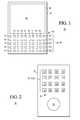
- FIGS. 1 and 2illustrate plan views of exemplary devices 20 , 30 having a large number of input electrodes 24 , 34 on input face 26 , 36 .
- FIG. 1is a plan view of generalized electronic device 20 having viewing screen 22 and x,y array 23 of input electrodes 24 on face 26 of case 25 .
- device 20 of FIG. 1has fifty input electrodes 24 in x,y array 23 , but larger or smaller numbers may be provided in other embodiments.
- FIG. 2is a plan view of generalized electronic device 30 having control wheel 32 and x′,y′ array 33 of input electrodes 34 on face 36 of case 35 .
- Array 23e.g., x,y
- array 33e.g., x′,y′
- X,Ythe row number in the array
- the designation i,jis intended to refer to any electrode of the array from 1,1 to X,Y, that is, the input electrodes in the arrays 23 , 33 can take on values from 1,1 . . . i,j . . . X,Y where X and Y can have any values depending on the number of electrodes in the input array.
- the particular input arrays illustrated hereinare presented by way of example and not limitation.
- Devices 20 and 30differ in that device 20 includes display 22 of some type and device 30 has no display but includes control wheel 32 of some type. Either arrangement or a combination thereof is useful, and the presence or absence of a display and/or control wheel is not important to the illustrated embodiments.
- Such deviceshave self-contained energy supplies (e.g., batteries, fuel cells, etc.) but this is not essential and embodiments described herein apply to both portable and plug-in types of devices and to any type of device intended to receive user input via contact with and/or proximity to input electrodes (real or virtual) by a finger or stylus or analogous instrument controlled by the user or by the input electrodes of the unit as a whole being brought into proximity with a part of the body (e.g., head, ear, etc.) or other large conductive object.
- energy suppliese.g., batteries, fuel cells, etc.
- the terms “input element” and “activation element”are intended to be interpreted broadly and include any object by which the user interacts with the input electrodes, as for example but not limited to one or more fingers, a stylus or various other instruments adapted for approaching or touching the input electrode to register an input or for approaching or touching groups of electrodes, as for example in the situation where the unit is being brought into proximity with a head or ear, etc.
- the parenthetical phrase “e.g., a finger, stylus, or ear”is included in the text that follows at various places as a reminder of the comprehensive definition provided above and not as a further limitation, where the word “stylus” is intended to refer to any hand-held object that may be used to activate input electrodes.
- proximity or touch sensing inputsmay be free standing electrodes, such as are shown in FIGS. 1-2 , or may be incorporated in a display screen in the form of virtual electrodes or may be a combination thereof. Either arrangement is useful.
- useful alternative sensing techniquesare optical sensing, magnetic field sensing and combinations of optical, electric and/or magnetic field sensing, which may be used instead of the electric field sensing illustrated herein.
- the words “input electrode” and equivalents, singular or plural,are intended to include any form of input activation device that is proximity and/or contact sensitive, including but not limited to those mentioned above in either physical or virtual form or both. Further, the designation “electrode” is not intended to imply that actual physical contact between the activation element and the input electrode is required, although it is not precluded. “Proximity sensitive” means that the electrode or other sensing means is adapted to detect the approach of the input element (e.g., a finger, stylus or ear) even before contact is or may be made.
- the input electrodesmay be very small, especially where the device itself is intended to be hand-held and a large number of input electrodes need to be included.
- Common examplesare devices incorporating a “qwerty” keyboard, a 10 to 12-key number and/or symbol pad, and other multifunction input electrode arrays.
- Each electrodeis usually small and the array of electrodes can take up substantially the entire available space on the input face of the device, especially if the device also incorporates a large display.
- Device 20 of FIG. 1illustrates this situation where the combination of display 22 and input electrode array 23 consumes nearly all of the space available on input face 26 of device 20 .
- a problem with this situationis that there is no room left on input face 26 for a large area electrode or sensing element to be used for general proximity detection.
- the various embodiments described hereovercome this limitation by dynamically combining individual input electrodes into a large area common electrode for general proximity sensing purposes, and then automatically returning the electrodes of the combination to individual sensing status. Detection selectivity is enhanced in further embodiments by coupling selected electrodes together to form a driven shield element surrounding or adjacent to a particular electrode that is being sensed. It will be further noted that even though device 30 of FIG. 2 may have sufficient unused space on input surface 36 to accommodate a larger area general proximity detection element, this can add undesirable additional cost. Thus, the various embodiments described herein for achieving the electrical equivalent of a large area proximity detection element are useful even where the device has sufficient space to accommodate a dedicated large area proximity detection element.
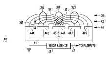
- FIGS. 3-6are simplified schematic side or cross-sectional views of arrangements 40 , 50 , 60 , 60 ′ of portions of electrode arrays 23 , 33 of devices 20 , 30 of FIGS. 1-2 illustrating how approaching input element 38 (e.g., a finger, stylus or ear) can perturb electric field 42 , 52 , 62 , 62 ′ associated with a particular input electrode i,j or combination of input electrodes, according to embodiments of the present invention.
- FIG. 3illustrating arrangement 40 with substrate 41 having thereon centrally located electrodes 441 , 442 , 443 and peripheral electrodes 444 , 445 laterally outboard thereof on substrate 41 .
- Centrally located electrodes 441 - 443 and peripheral electrodes 444 - 445are collectively referred to as electrodes 44 and are assumed in this example to be capacitive elements so that variations in the electric field associated therewith may be detected by sensing changes in the apparent capacitance of the input electrodes.
- middle electrode 441is being driven and sensed, that is, it is coupled by lead 45 to individual electrode driver and sense (IE DR & SENSE) element 46 .
- Adjacent electrodes 442 - 445are coupled to the reference potential of IE DR & SENSE element 46 .
- groundground
- GNDground
- the interior details of substrate 41 , electrodes 44 and IE DR & SENSE element 46are omitted in FIGS. 3-6 to avoid unduly cluttering the drawings.
- Input element 38(e.g., a finger, stylus or ear) is illustrated in three positions located above electrodes 44 of FIG. 2 by similar distances 384 ; wherein middle position 381 is above sensed electrode 441 and positions 382 - 383 are above grounded electrodes 442 - 443 on either side of sensed electrode 441 .
- Lines 371schematically illustrate electric field 42 in FIG. 3 between middle (sensed) electrode 441 and neighboring grounded electrodes 442 - 445 when biased by IE DR & SENSE element 46 .
- IE DR & SENSE element 46comprises, by way of example and not intended to be limiting, a conventional pulsed (e.g., square wave) constant current source (not shown) for driving electrode 441 and a conventional voltage measuring device (not shown) for sensing the voltage appearing on electrode 441 in response to the constant current pulse supplied by IE DR & SENSE element 46 .
- a conventional pulsed (e.g., square wave) constant current sourcefor driving electrode 441
- a conventional voltage measuring device(not shown) for sensing the voltage appearing on electrode 441 in response to the constant current pulse supplied by IE DR & SENSE element 46 .
- Electrode 441is assumed to be substantially a capacitive element, that is, to have negligible ohmic leakage. The voltage on electrode 441 begins to rise as the capacitance associated with electrode 441 is charged by the current drive pulse supplied by IE DR & SENSE element 46 , thereby creating electric field 42 .
- the voltage rise associated with charging the capacitance of electrode 441is detected (i.e., “sensed”) by IE DR & SENSE element 46 .
- the proximity of input element 38e.g., a finger, stylus or ear
- This apparent change in capacitancecauses the voltage response detected by IE DR & SENSE element 46 to be different depending upon the presence or absence and proximity of input element 38 . It is often the case that the closer input element 38 is to sensed electrode 441 , the larger the apparent capacitance and the smaller the voltage rise for a given amount of charge supplied by the current drive pulse from IE DR & SENSE element 46 .
- the voltage response detected by IE DR & SENSE element 46is reported via sensed voltage output 47 to, for example, filter 76 of detection system 70 of FIG. 7 , whose operation is explained later.
- the combination of IE DR & SENSE element 46 and electrode 441can serve as a proximity detector even before physical contact occurs between input element 38 and electrode 441 .
- the proximity response detected by arrangement 40is largest when input element 38 is in position 381 directly over middle (sensed) electrode 441
- the fringing of electric field 42 between middle electrode 441 and adjacent (e.g., grounded) electrodes 442 - 445limits the precision in detecting the topographical location of input element 38 (e.g., a finger, stylus or ear).
- FIG. 4illustrating arrangement 50 with substrate 41 having thereon centrally located electrodes 441 , 442 , 443 and peripheral electrodes 444 , 445 laterally outboard thereof on substrate 41 .
- Centrally located electrodes 441 - 443 and peripheral electrodes 444 - 445are collectively referred to as electrodes 44 and are assumed in this example, as with arrangement 40 , to be capacitive elements.
- middle electrode 441is being driven and sensed, that is, it is coupled by lead 45 to individual electrode driver and sense (IE DR & SENSE) element 46 , the same as in FIG. 3 .
- adjacent electrodes 442 - 445are not coupled to GND as they were in FIG. 3 .
- Sensed voltage output 47 of IE DR & SENSE element 46is coupled for example, to filter 76 of detection system 70 of FIG. 7 and to input 55 of amplifier 56 .
- Output 57 of amplifier 56is coupled to peripheral electrodes 442 - 445 and, in some embodiments, also to input 743 of multiplexer 74 of detection system 70 of FIG. 7 .
- Amplifier 56is desirably an operational amplifier, so that adjacent electrodes 442 - 445 have the same potential as sensed electrode 441 .
- the output of amplifier 56 on lead 57 coupled to electrodes 442 - 445is referred to as the “shield drive voltage,” abbreviated as SDV.
- Electrodes 442 - 445 adjacent to sensed electrode 441function as a driven shield having the same electrical potential (i.e., the SDV) as sensed electrode 441 .
- the SDVelectrical potential
- Remote ground 51can be located anywhere. It will be apparent that input element 38 only perturbs electric field 53 when in position 381 above central electrode 441 and has substantially little or no effect when in positions 382 , 383 .
- arrangement 50is capable of much greater positional accuracy in proximity detection of input element (e.g., a finger, stylus or ear) 38 . While it may provide higher positional accuracy, it is not especially useful for general proximity detection since input element 38 must be close to individual sensed electrode 441 before a significant change in capacitance of electrode 441 can be detected by IE DR & SENSE element 46 .
- FIG. 5illustrating arrangement 60 with substrate 41 having thereon centrally located electrodes 441 , 442 , 443 and peripheral electrodes 444 , 445 generally laterally outboard thereof on substrate 41 .
- Centrally located electrodes 441 - 443 and peripheral electrodes 444 - 445are collectively referred to as electrodes 44 and are assumed in this example to be capacitive elements, as in connection with FIGS. 3-4 .
- central electrode 441is being driven and sensed, that is, it is coupled by lead 65 to proximity driver and sense (PROX DR & SENSE) element 66 .
- Adjacent electrodes 442 - 443are also coupled in parallel with electrode 441 to drive-sense lead 65 .
- Electrodes 444 - 445are coupled to the reference potential of PROX DR & SENSE element 66 , e.g., GND.
- PROX DR & SENSE element 66is similar in construction and operation to IE DR & SENSE element 46 but adapted to operate at higher current since it is driving the combination of several electrodes 441 - 443 , and in some embodiments, may be driving most or all of available electrodes 44 .
- electric field 62schematically indicated by lines 374 extends from parallel coupled electrodes 441 - 443 to GND electrodes 444 - 445 .
- input element 38e.g., a finger, stylus or ear
- input element 38can be in any of positions 381 , 382 ′, 383 ′ as indicated by bracket 386 and at greater distance 385 from combined electrodes 441 - 443 and still have substantial impact on the apparent capacitance of combined electrodes 441 - 443 .
- arrangement 60is better suited to general proximity detection since it can detect the presence of input element 38 over a wider extent 386 and at greater distances 385 from electrodes 441 - 443 .
- PROX DR & SENSE element 66reports changes in apparent capacitance of parallel coupled electrodes 441 - 443 caused by the approach of input element 38 (e.g., a finger, stylus or ear) via sensed voltage output 67 to, for example, filter 76 of detections system 70 of FIG. 7 .
- Arrangement 60 ′ of FIG. 6is substantially similar to arrangement 60 of FIG. 5 and operates in generally the same manner. Accordingly, the discussion of arrangement 60 is generally relevant to arrangement 60 ′.
- Arrangements 60 and 60 ′differ in that substantially all electrodes 441 - 445 of arrangement 60 ′ are coupled in parallel to drive-sense lead 65 of PROX DR & SENSE element 66 so that they act cooperatively.
- Electric field 62 ′(e.g., indicated schematically by lines 375 ) has greater lateral extent, so that input element 38 (e.g., a finger, stylus or ear) is detectable at locations 382 ′′, 383 ′′ over greater lateral spacing 387 and/or at greater distanced 385 ′.
- input element 38e.g., a finger, stylus or ear
- General proximity detectionis a very useful feature. For example, it may be used to “wake-up” a sleeping device from a low power state so as to be ready to detect inputs at specific individual electrodes or otherwise respond to the user or to an incoming signal or other input. As a further example, detecting that a cell phone is being brought into proximity to an ear (or otherwise approaching the head) may be used to prompt the cell phone to answer an incoming call or turn on the microphone in the cell phone or active some other function.
- such a “wake-up” functionmay also be used to turn on internal lights so as to illuminate the individual electrodes and/or portions or all of the display (if present) and/or other elements, which in a darkened or quiescent state would be difficult for the user to see or to activate.
- overall power consumptionnot only can overall power consumption be reduced by facilitating a sleep state and associated wake-up function, but overall usability can be enhanced with little or no additional power consumption by, for example, turning on the internal electrode lights, display screen or other elements, answering an incoming call or turning on an internal microphone or other features and so forth, when an input command or call or equivalent directive is about to be received.
- the availability of general proximity detectionscan be a significant advantage.
- FIG. 7is a simplified schematic block diagram of electronic system 70 for incorporating a proximity detection function using combinations of already available individual input electrodes 44 and FIGS. 8-10 show truth-tables 108 - 110 illustrating a method by which system 70 of FIG. 7 automatically switches between sensing the state of individual electrodes 44 and a general proximity detection function using a parallel connections of such individual electrodes 44 or both.
- System 70is able to establish any of the configurations illustrated in FIGS. 3-6 and automatically accommodates both a general proximity sensing mode (e.g., as in FIGS. 5-6 ) and an individual electrode sensing mode (e.g., as in FIGS. 3-4 ) and combinations thereof.
- a general proximity sensing modee.g., as in FIGS. 5-6
- an individual electrode sensing modee.g., as in FIGS. 3-4
- System 70comprises clock 71 , sequencer 72 associated with multiplexer (MUX) 74 , amplifier 56 , individual electrode driver and sense (IE DR & SENSE) element 46 , proximity driver and sense (PROX DR & SENSE) element 66 , filter 76 , memory 77 , comparator 78 , and system controller 79 .
- Filter 76receives the sensed voltage signals from IE DR & SENSE element 46 and from PROX DR & SENSE element 66 as explained in connection with FIGS. 3-6 .
- Filter 76is preferred but may be omitted in other embodiments or its function may be achieved in other conventional ways. As indicated in FIG.
- filter 76may be a single filter shared by both IE DR & SENSE element 46 and PROX DR & SENSE element 66 , or may comprise separate filters 76 ′, 76 ′′ one for each of elements 46 , 66 each providing outputs 761 , 762 . Either arrangement is useful. Individual filters 76 ′, 76 ′′ are referred to collectively as filter 76 .
- Filter 76is conventional and functions as a low pas filter that strips off higher frequency noise that may be present on the signals coming from drive-sense elements 46 , 66 .
- Output 761 from filter 76is coupled to memory 77 and output 762 is coupled to comparator 78 .
- Memory 77stores the output of filter 76 for one or more drive-sense cycles and then delivers these stored values to comparator 78 .
- the last sense voltage signale.g., from output 47 from IE DR & SENSE element 46 via filter 76
- the last sense voltage signale.g., from output 67 from PROX DR & SENSE element 66 via filter 76
- the last sense voltage signale.g., from output 67 from PROX DR & SENSE element 66 via filter 76
- Memory 77stores the output of filter 76 for one or more drive-sense cycles and then delivers these stored values to comparator 78 .
- the last sense voltage signale.g., from output 47 from IE DR & SENSE element 46 via filter 76
- the last sense voltage signale.g., from output 67 from PROX DR & SENSE element 66 via filter 76
- Filter 76 , memory 77 and comparator 78act cooperatively to compare currently sensed-voltage readings with immediate past readings for the corresponding input elements or to compare currently sensed-voltage readings to a weighted average or other integrated (e.g., smoothed) functions of various past readings, according to the type of comparison function desired by the system designer or user. Techniques for accomplishing such comparison functions are well known in the art.
- comparator 78Based on the threshold criteria built-into filter 76 or comparator 78 and comparison criteria built into memory 77 and comparator 78 , comparator 78 provides output 781 to system controller 79 indicating whether an input element is approaching or has contacted a particular input electrode or, for general proximity sensing or other purposes, a group of input electrodes.
- System controller 78passes on the recognized input electrode proximity or touch to the remainder of the device for appropriate action consistent with whichever input electrode or group of electrodes has been approached or touched or both.
- the details of system controller 79 and the remainder of the devicewill depend upon the particular device being created (e.g., a cell phone, PDA, entertainment device, etc., as have been mentioned earlier) and are within the skill of the designer of such devices.
- system controller 79can also under appropriate circumstances send a signal back to sequencer 72 via MODE SELECT output 792 to change the action of multiplexer 74 to better identify the prospective target of an approaching input element and perform other specialized functions. This is discussed in more detail in connection with FIGS. 9 and 10 .
- IE DR & SENSE element 46provides (via output 45 coupled to I/O connection 741 of MUX 74 ) individual electrode drive current to and senses the resulting voltage building up (collectively the ID&S signals) on the individual electrode to which it is connected by switch array (SA) 75 of multiplexer (MUX) 74 .
- PROX DR & SENSE element 66provides (via output 65 coupled to I/O connection 742 of MUX 74 ) drive current to and senses the resulting voltage (collectively the PD&S signals) building up on the combination of electrodes to which it is connected by SA 75 of MUX 74 .
- output 47 of IE DR & SENSE element 46is also coupled to input 55 of amplifier 56 whose output 57 is coupled to I/O connection 743 of MUX 74 .
- Output 57is an amplified version of the detected voltage portion of the ID&S signal of a particular individual electrode being sensed. This amplified signal is also referred to as the shield drive voltage (abbreviated as “SDV”). Since amplifier 56 is conveniently an operational amplifier, its SDV output 57 matches the voltage signal being sensed on the individual electrode to which IE DR & SENSE element 46 is coupled by MUX 74 .
- I/O connection 744 of MUX 74is coupled to GND.
- I/O ports 73are coupled to the individual electrodes 24 , 34 , 44 of device 20 or 30 of FIGS. 1-2 and/or portions 40 , 50 , 60 , 60 ′ of FIG. 3-6 .
- Switch array (SA) 75couples one or more of I/O ports 73 leading to and from individual electrodes 24 , 34 , 44 to I/O ports 741 , 742 , 743 and/or 744 as indicated in tables 108 - 110 of FIGS. 8-10 .
- SASwitch array
- switch 75i,j
- SA 75switch array
- Clock 71 of system 70provides timing signals ⁇ to sequencer 72 of multiplexer (MUX) 74 via clock output 711 and to such other elements of system 70 as may also use a timing signal via output 712 .
- MUXmultiplexer
- the individual connections of timing signals ⁇ to other elements of system 70are omitted to avoid cluttering the drawing and obscuring the invention, since clock distribution arrangements are well known in the art and within the competence of persons of ordinary skill in electronic design.
- Timing signals ⁇be sufficiently rapid so that the individual electrode and general proximity and/or contact detection functions provided by system 70 occur in a time period less than the time period in which humans can provide input signals to the device, for example, less than the time it takes a finger, stylus or ear to approach and/or touch electrodes 24 , 34 , 44 .
- Sequencer 72generates logical control signals S 1 , S 2 (see tables 108 - 110 of FIGS. 8-10 ) preferably regulated by the timing signals ⁇ from clock 71 .
- Logical control signals S 1 , S 2are fed to switch array (SA) 75 , one of which (e.g., representative switch 75 ( i,j )) is shown in MUX 74 .
- SAswitch array
- logical control signals S 1 , S 2determine which of I/O ports 741 - 744 having respectively ID&S, PD&S, SDV signals and GND are coupled by SW 75 ( i,j ) to I/O port 73 ( i,j ) leading to individual electrode i,j.
- S 1 , S 2can take on the logical values, 11, 10, 01, or 00 where the 1 and 0 indicate opposite binary states. (Even though a comma is used between S 1 , S 2 , no comma is used between the logical state designators 11, 10, 01 and 00 to avoid confusion with the identification of individual electrodes, e.g., 1,1, 2,1, . . .
- sequencer 72 in combination with SA 75can couple any of the 1,1 . . . i,j, . . . X,Y electrodes 24 , 34 , 44 to any combination of I/O ports 741 - 744 having, respectively ID&S, PD&S, SDV signals and GND.
- individual electrodes i,jbe coupled sequentially via I/O ports 73 ( i,j ) individually and in combination through switches 75 ( i,j ) to I/O ports 741 - 744 .
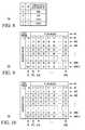
- To couple electrodes sequentiallymeans to couple them one after the other. This sequential coupling may be done in any desired order. How this is accomplished in a preferred embodiment is illustrated in tables 109 - 110 of FIGS. 9-10 . Referring now to table 109 of FIG. 9 , the various electrodes 1,1 . . . i,j, . . .
- electrode 1,1is listed at the top of column 91 ( 1 )
- electrode 2,1at the top of columns 91 ( 2 )
- electrode X,Yat the top of column 91 (N).
- X,Yis individually coupled, one at a time, to one or more of I/O ports 741 - 744 in sequential stages 1 thru N, and collectively coupled in further stage N+1.
- first electrode 1,1 in column 91 ( 1 )is coupled to ID&S I/O port 741 as indicated by the logical state 11 in the 1,1 (i.e., 91 ( 1 )) column of row 90 ( 1 ) and all other electrodes 2,1 . . . X,Y (e.g., in columns 91 ( 2 ) . . . 91 (N)) are coupled to GND port 744 as indicated by logical state 00 in the remainder of entries in row 90 ( 1 ).
- electrode 1,1 in column 91 ( 1 )is coupled to GND port 744 as indicated by logical state 00 in the 1,1 (i.e., 91 ( 1 )) column of row 90 ( 2 )
- second electrode 2 , 1 in column 91 ( 2 )is coupled to ID&S I/O port 741 as indicated by the logical state 11 in the 2,1 ( 91 ( 2 )) column of row 90 ( 2 )
- all other electrodes 3 , 1 . . . X,Y in columns 91 ( 3 ) . . . 91 (N)are coupled to GND port 744 as indicated by logical state 00 in the remainder of entries in row 90 ( 2 ).
- Electrodes 1,1 . . . i,j . . . X,Yhave been individually coupled as shown in table 109 in stages 1 through N, then in stage N+1, electrodes 1,1 . . . i,j . . . X,Y are parallel coupled to PD&S I/O port 742 as indicated by the logical state 10 in columns 91 ( 1 ) thru 91 (N) of row 90 (N+1) of stage N+1.
- Thishas the effect of coupling all of electrodes 24 , 34 , 44 in configuration 60 ′ of FIG. 6 (or configuration 60 of FIG. 5 with outer electrodes 444 - 445 grounded by use of logical state 00 therefore) and provides an effective large area proximity detection capability since all or nearly all electrodes contribute to the effective proximity element area.
- the input electrodesmay also be parallel-coupled in various subgroups of less than all the input electrodes to accomplish various other functions desired by the designer and/or user.
- Such sub-groupingsmay be built into sequencer 72 or programmable, as for example, via mode select control 792 from system controller 79 . An example of such arrangement is given in connection with the discussion of FIGS. 9-10 .
- the time required to cycle from stages 1 thru N+1be less than the approach time of input element 38 (e.g., a finger, stylus or ear).
- this duration T ONbe less than or equal to about 32 microseconds, more conveniently less than or equal to about 1.0 microseconds and preferably less than or equal to about 0.5 microseconds. The time required to sense the achieved voltage does not add significant time.
- T OFFa second approximately equal interval T OFF is provided after the constant current drive and voltage sense is complete to allow the voltage to return substantially to zero before another drive-sense stage is initiated on another input electrode.
- T H80 milliseconds seconds to move input element 38 (e.g., a finger, stylus or ear) in such a way as to significantly influence an individual electrode or composite proximity electrode, that is, to significantly change the apparent capacitance.
- input element 38e.g., a finger, stylus or ear
- T PerStagethe individual input electrode drive-sense time per stage
- TTis less than T H it will appear to the user that the device is responding to any input electrode approach or contact without significant delay, both for general proximity purposes as well as individual electrode proximity or contact purposes.
- input element 38e.g., a finger, stylus or ear
- itwill be detected during the proximity stage (e.g., stage N+1) of each array drive-sense cycle (states 1 through N+1) before it can come into contact with any electrode i,j, and the device actuated as desired by the designer, e.g., electrode array lights turned on, phone answered or whatever.
- input element 38e.g., a finger, stylus or ear
- other wake-up functions or call answering functionscan be executed as the increased proximity of the input element is detected during subsequent overall array drive-sense cycles.
- the devicewill appear to function as if it had a large area independent proximity detection element, when in fact it does not, and the proximity detection function is being achieved by rapidly multiplexing a large number or all of the individual input electrodes together in real time for proximity sensing and then returning them to individual (or subgroup) sensing mode until all have been scanned, and then repeating the multiplexed and individual (or subgroup) scanning steps during the next overall drive-sense cycle.
- a general proximity functioncan be provided for devices that otherwise have no space for a large area dedicated general proximity sensing element.
- Table 110 of FIG. 10A further embodiment of the invention is illustrated in table 110 of FIG. 10 .
- Table 110 of FIG. 10is very similar to table 109 of FIG. 9 , except S 1 , S 2 inputs to determine the logical state of switches 75 ( i,j ) of array 75 are modified so that that instead of coupling various electrodes i,j during stages 1 through N to GND port 744 , as shown by the 00 entries in table 109 of FIG. 9 , in table 110 , such entries are replaced by logical state 01 so that such i,j electrodes are coupled (per table 108 ) to shield drive voltage (SDV) input port 743 .
- SDVshield drive voltage
- system 70can in this further embodiment switch to configuration 110 and vary the combinations of sensed electrodes and surrounding SDV coupled electrodes to narrow the positional identification of the target electrode intended by input element 38 (e.g., a finger, stylus or ear).
- system 70can, using an arrangement similar to that illustrated in table 110 and FIG. 4 , chose each of the four proximate electrodes in turn as sensed electrode 441 coupled to port 741 and surrounded by electrodes coupled to SDV port 743 , thereby forming configuration 50 of FIG. 4 in two dimensions.
- the intended target input electrodecan be better identified because of the improved spatial detection capabilities associated with configuration 50 , especially when executed in two dimensions.
- Any number of proximate electrodes greater than or equal to two input electrodescan be sampled in this way to improve the positional accuracy of proximate input electrode detection.
- the input electrodes being sampled surrounded by or adjacent to SDV coupled electrodesneed not be arranged in a square but may be in any other geometric configuration depending on the number of proximate electrodes involved. Non-limiting examples of such other arrangements are input electrodes arranged in a line, a cross, a polygon, a rectangle, a circle or ellipse or other arbitrary geometrical configuration.
- the particular embodimente.g., arrangements 40 , 50 , 60 , 60 ′ and/or the configurations of tables 109 or 110 , are not fixed but can be varied during the course of the approach of an input element, and the number of individual electrodes arranged in groups dynamically varied to improve the overall functioning of the device. This is a further important advance in the art.
- FIGS. 11-13are simplified schematic block diagrams illustrating methods 200 , 300 , 400 for sensing the state of various combinations of individual, group and general proximity input electrode 23 , 24 , 44 and modifying the state of devices 20 , 30 of FIGS. 1-2 based thereon, according to yet further embodiments of the invention.
- Methods 200 , 300 , 400are executed by system 70 of FIG. 7 , keeping in mind the various input electrode arrangements illustrated in FIGS. 3-6 and further explained in connection with FIGS. 8-10 .
- method 200begins with START 200 and initial step 204 that can occur when device 20 , 30 is powered up.
- initial step 204individual input electrodes 1,1 . . . i,j . . .
- X,Yare sensed one at a time as has been explained in connection with FIGS. 3-4 and 7 - 9 or 3 - 4 , 7 - 8 and 10 , and the result of such sensing operations reported to system controller 79 , which in step 206 , modifies (i.e., changes or alters) the state of devices 20 , 30 via output 791 if a change in state of the sensed electrode has been detected. For example, if system 70 determines that input electrode i,j has received a valid input (either by proximity or actual or virtual touch), where input electrode i,j is, for instance, part of a numerical keypad, then the value ascribed to input key i,j is entered into the device electronics via controller output 791 .
- each individual input electrodeis tested (e.g., sequentially sensed) in turn, as been described for example in connection with FIGS. 8-9 , to determine whether or not a valid input has been received and each such input or lack thereof is reported to device 20 , 30 for appropriate action corresponding to which input(s) have been activated or not activated.
- step 206has been completed for the individual input electrodes, method 200 proceeds to step 208 in which some or all individual input electrodes are coupled together in parallel to form a large area proximity sensing element, as has been described in connection with FIGS. 5-6 and step N+1 of FIG. 9 or 10 .
- step 210the parallel combinations of some or all of electrodes 24 , 34 , 44 is sensed and the result reported in substantially the same manner as for the individual electrodes as has already been explained in connection with the discussion of FIGS. 5-9 and/or 5 - 8 and 10 .
- step 212the state of device 20 , 30 is modified or not according to the results of step 210 , as for example, turning on the lights under the input keys or answering a cell phone incoming call or whatever, when the proximity detect mode of stage N+1 of FIG. 9 or 10 has detected an approaching input element (e.g., a finger, stylus or ear).
- an approaching input elemente.g., a finger, stylus or ear
- step 214the parallel coupled input electrodes arranged in step 208 are decoupled so as to be ready to return to the individual input electrode sensing mode following subsequent query 216 .
- query 216it is determined whether or not device 20 , 30 is still ON, that is still activated. If the outcome of query 216 is YES indicating that device 20 , 30 is still powered up, then as shown by path 217 , method 200 returns to initial step 204 and steps 204 - 214 repeated until the outcome of query 216 is NO, whereupon as shown by path 218 , method 200 proceeds to END 220 .
- steps 204 - 206 and 208 - 214may be performed in any order, that is, the individual electrodes may be sensed in any order and the device state modified accordingly, and the individual electrodes may be grouped in any combination and sensed and the state of the device modified accordingly, etc., before or after the individual electrodes are sensed, etc.
- method 300begins with START 302 and initial step 304 .
- an individual input electrodee.g., electrode i,j
- an individual input electrodeis chosen to be sensed, as has been described in connection with FIGS. 3-4 , 7 - 9 or 3 - 4 and 7 - 9 and 10 .
- the state of the chosen input electrodeis sensed, that is, it is determined, for example by measuring the voltage response when input electrode i,j is driven by a constant current or other charge source, whether the apparent capacitance (e.g., sensed by the voltage rise) of the electrode indicates that an input element is near or in contact with input electrode i,j, as has been previously explained.
- query 308it is determined, for example using a combination of IR DR & SENSE element 46 , filter 76 , memory 77 and comparator 78 , whether or not the sensed signal on input electrode i,j (that is the “state” of electrode i,j) indicates that the activation threshold for such input electrode has been passed.
- the input elemente.g. a finger, stylus or ear
- the input elemente.g. a finger, stylus or ear
- the activation thresholdhas not been passed (e.g., NO outcome of query 308 )
- the input elemente.g., finger, stylus or ear
- the outcome of query 308is NO, then method 300 proceeds via path 309 to query 312 wherein it is determined whether or not all electrodes 1,1 . . . i,j . . . X,Y have been sensed.
- step 316wherein another input electrode (e.g., i+1, j+1) is chosen and method 300 then proceeds back to step 306 so that the sequence of steps 306 - 308 is repeated until a YES outcome is obtained from either query 308 or 312 .
- step 310If the outcome of query 308 is YES, then as shown by path 310 , method 300 proceeds to step 318 wherein the state of the device (e.g., device 20 , 30 ) is changed based on the activation of the individual electrode by approaching or contacting input element 38 (e.g., a finger, stylus or ear).
- input element 38e.g., a finger, stylus or ear
- step 318if in a key-pad, the input electrode corresponding to the + sign has been activated, then system controller 79 issues an “ADD” instruction via output 791 to the device electronics.
- step 318if the outcome of query 312 is YES leading to path 314 , then method 300 proceeds to step 320 in which some or all of the individual input electrodes 24 , 34 , 44 are coupled in parallel, as for example is illustrated in step N+1 of FIG. 9 or 10 and/or in FIGS. 5-6 .
- step 322the state of the parallel coupled input electrodes is sensed as has already been described in connection with FIGS. 5-7 .
- step 324it is determined whether or not the state of the parallel coupled electrodes passes the activation threshold for general proximity detection. This is accomplished in generally the same manner as has already been explained in connection with FIGS. 5-7 for general proximity detection and in connection with step 308 for an individual electrode. If the outcome of query 324 is NO, then as shown by path 325 , method 300 proceeds to decoupling step 330 .
- method 300proceeds via path 326 to step 328 in which the state of the device (e.g., device 20 , 30 ) is changed based on the general proximity activation determined in step 324 , before proceeding to decoupling step 330 wherein the parallel coupled input electrodes are decoupled in preparation for a return to the individual input electrode sensing mode of steps 304 and following. Following decoupling step 330 , method 300 proceeds to query 332 wherein it is determined whether or not the device is still ON (e.g., still powered up).
- the deviceis still ON (e.g., still powered up).
- method 300proceeds via path 333 to initial step 304 and the sequential individual input sense plus parallel coupled input electrodes sense cycle is repeated until the outcome of query 332 is NO, whereupon method 300 proceeds via path 334 to END 336 .
- FIG. 13illustrates method 400 by which the destination of an input element (e.g., a finger or stylus) may be more accurately anticipated, as has been previously mentioned in connection with the discussion of FIGS. 7 and 10 .
- Method 400begins with START 402 and initial step 404 , in which input element 38 (e.g., a finger, stylus or ear) is sensed approaching a group of individual input electrodes. This situation can arise when a subset of individual input electrodes has been grouped together or where, for example, the situation resembles arrangement 40 of FIG.
- input element 38e.g., a finger, stylus or ear
- proximate electrodesmay comprise any number of individual input electrodes, generally adjacent and grouped in some fashion, as for example, arranged in the form of a square, rectangle, polygon, circle, ellipse, triangle, line, cross, and so forth. The precise two dimensional layout in which the proximate electrodes are arranged is not critical.
- system controller 79issues a mode change instruction on output 792 , whereupon sequencer 72 and MUX 74 of system 70 selects one of the proximate electrodes (e.g., electrode i,j) as the sensed electrode coupled to ID&S input 741 of FIG. 7 from IE DR & SENSE element 46 .
- proximate electrodese.g., electrode i,j
- Surrounding or adjacent electrodesare coupled to SDV input 743 of FIG. 7 , so that such non-sensed electrodes act as a driven shield coupled via amplifier 56 to voltage sense output 47 of IE DR & SENSE element 46 .
- the voltage of such driven shield electrodesfollows the voltage of sensed element i,j and the electric field associated with electrode i,j is highly localized (e.g., see FIG. 4 ) so that it may more accurately respond to approaching input element 48 .
- the state of sensed electrode I,jis determined and stored in memory 77 , as has already been explained in connection with the discussion of one or more of FIGS. 3-10 .
- query 412it is determined whether or not all of the proximate electrodes have been sensed and their state stored in memory 77 . (In other embodiments, rather than all results being stored, only those passing a predetermined significance threshold may be stored.).
- step 415in which another of the proximate electrodes is chosen as the sensed electrode and steps 408 - 412 repeated until all proximate electrodes have been sensed using the configuration of arrangement 50 of FIG. 4 and the significant results stored in memory, that is, until the outcome of query 412 is YES.
- Method 400then proceeds to step 417 wherein the stored state values for the various proximate electrodes are compared so that the proximate electrode most perturbed by incoming input element 38 and therefore the closest thereto can be identified.
- query 418it is determined whether or not the closest electrode to the input element can be identified.
- method 400proceeds via path 419 to query 422 wherein it is determined whether a predetermined number M of trials has been completed. The purpose of this query is to prevent system 70 from becoming trapped in an endless loop in case no single input electrode is determined to be the closest to approaching input element 38 . If the outcome of query 422 is NO, indicating that the maximum number M of trials has not been reached, then method 400 loops back via path 423 to steps 406 - 418 and tries again, seeking to identify the closest electrode to input element 38 .
- step 425in which the results of the proceeding steps are reported to system controller 79 .
- Thismay be, for example, the identification of the input electrode closest to approaching input element 38 (e.g., a finger, stylus or ear) or the group of input electrodes closest to input element 38 . The latter situation can occur, for example, when the input element is equally spaced from several input electrodes.
- This informationcan be effectively used by the device (e.g., device 20 , 30 ) in step 426 wherein the state of the device is modified based on the results reported in step 425 , assuming that the results differ significantly from a predetermined action threshold.
- the devicecan use in step 426 the information provided in step 425 to light the input electrode or small group of input electrodes closest to the approaching input element, thereby leading the user into the desired input electrode.
- method 400can proceed to query 428 in which it is determined whether the device is still ON or the described feature still active?.
- method 400can proceed via path 439 back to initial step 404 and the sequence repeated until the outcome of query 428 is NO, whereupon method 400 proceeds to end 432 .
- the capability illustrated in method 400may be always ON (e.g., active whenever device 20 , 30 is powered up) or may be selected by an appropriate ON/OFF switch, in which case query 428 checks to see whether this switch is in the ON of OFF position. Either arrangement is useful.
- the sensing, reporting and modifying steps for the individual input electrodescomprise, choosing an individual input electrode ( 24 , 34 , 44 ) to be sensed, sensing the state of the chosen input electrode ( 24 , 34 , 44 ) by measuring a signal ( 47 ) affected by the approach or contact of an input element ( 38 ) to the chosen input electrode ( 24 , 34 , 44 ), testing whether the measured signal ( 47 ) passes a predetermined threshold, and if YES, changing the state of the device ( 20 , 30 ), and if NO, choosing another individual input electrode ( 24 , 34 , 44 ) and repeating the sensing and threshold testing steps until all input electrodes ( 24 , 34 , 44 ) of interest have been chosen, sensed and threshold tested.
- the methodfurther comprises, first choosing one of the more than one input electrodes ( 24 , 34 , 44 ) as the first chosen input electrode ( 24 , 34 , 44 ) to be sensed and coupling others of the more than one input electrodes ( 24 , 34 , 44 ) to a driven shield signal ( 57 ) derived from the first chosen input electrode ( 24 , 34 , 44 ), first sensing and reporting the state of the first chosen input electrode ( 24 , 34 , 44 ), and second choosing another of the one or more input electrodes ( 24 , 34 , 44 ) as a second chosen input electrode ( 24 , 34 , 44 ) to be sensed and coupling others of the more than one input electrodes ( 24 , 34 , 44 ) to a driven shield signal (
- the step of sensing the state of the individual input electrode ( 24 , 34 , 44 )comprises, driving the individual input electrode with a constant current and measuring the voltage appearing across the individual input electrode as a result of the constant current drive.
- the constant current driveis a constant current pulse of first predetermined duration.
- the step of measuring the voltageoccurs at a second predetermined time after the constant current drive starts.
- the step of reporting the state of the individual input electrodes and modifying the state of the devicecomprise, storing a first sensed state of the individual input electrode in a memory and then comparing the stored first sensed state with a second sensed state determined later in time so as to detect changes between the first and second sensed states and modifying the state of the device based at least in part on such changes.
- the step of sensing and reporting the state of the coupled input electrodescomprises, driving the coupled input electrodes with a constant current and measuring the voltage appearing across the coupled input electrodes as a result of the constant current drive.
- the constant current driveis a constant current pulse of first predetermined duration.
- the step of measuring the voltageoccurs at a second predetermined time after the constant current drive starts.
- an apparatus ( 20 , 30 ) for detecting proximity of an input element ( 38 ),comprising, multiple individual input electrodes ( 24 , 34 , 44 ), an individual electrode drive and sense element ( 46 ) having a drive-sense terminal ( 45 ) adapted to be coupled to the individual input electrodes ( 24 , 34 , 44 ) and having an output terminal ( 47 ) for reporting on the states of the individual input electrode ( 24 , 34 , 44 ) coupled to its drive-sense terminal ( 45 ), a proximity drive and sense element ( 66 ) having a drive-sense terminal ( 65 ) adapted to be coupled to parallel groups of the individual input electrodes and having an output terminal ( 67 ) reporting on the states of the parallel coupled groups of individual input electrodes ( 24 , 34 , 44 ) coupled to its drive-sense terminal ( 65 ), and a multiplexer ( 74 ) for sequentially coupling: (i) the individual input electrodes ( 24 , 34 , 44 ) to the
- the apparatusfurther comprises, a filter ( 76 , 76 ′) for receiving from the output terminal ( 47 ) of the individual electrode drive and sense element ( 46 ) first signals related to the states of the individual input electrodes ( 24 , 34 , 44 ), and a filter ( 76 , 76 ′′) for receiving from the output terminal ( 67 ) of the proximity drive and sense element ( 66 ) second signals related to the states of the parallel coupled individual input electrodes ( 24 , 34 , 44 ).
- the apparatusfurther comprises, a memory ( 77 ) having an input coupled to an output ( 761 ) of the filter ( 76 , 76 ′, 76 ′′) for temporarily storing signals determined by the states of the individual and parallel coupled individual input electrodes ( 24 , 34 , 44 ).
- the apparatusfurther comprises, a comparator ( 78 ) receiving an input from the memory ( 77 ) and an input from the filter ( 76 , 76 ′, 76 ′′) for comparing the state of various individual input electrodes ( 24 , 34 , 44 ) singly or in groups with previous values of the states of the same or other of the various individual input electrodes ( 24 , 34 , 44 ) or groups of electrodes ( 24 , 34 , 44 ).
- a comparator78
- the sensing and storing steps for the proximity or contact state of the individual input electrodes ( 24 , 34 , 44 )are performed sequentially in any order.
- the sensing and storing steps for the proximity or contact state of the one or more groups of input electrodes ( 24 , 34 , 44 )are performed during or after the sensing and storing steps for the proximity or contact state of the individual input electrodes ( 24 , 34 , 44 ).
- a time period used for the sensing, comparing and modifying steps for all input electrodesis less than human reaction time for approaching or contacting an input electrode.
- a time period for the sensing, comparing and modifying steps for an individual input electrodeis less than or equal to about 64 microseconds.
- the step of modifying the state of the device ( 20 , 30 )comprises lighting some of the input electrodes.
- an electronic apparatuscomprising, a plurality of individual input electrodes ( 24 , 34 , 44 ), a touch and proximity detection system ( 70 ) coupled to the plurality of individual input electrodes, wherein in a first mode, the detection system ( 70 ) provides an indication of whether or not an input element ( 38 ) has touched at least one of the individual input electrodes ( 24 , 34 , 44 ) and in a second mode provides an indication of whether or not an input element ( 38 ) is in proximity to a group of at least some of the individual input electrodes ( 24 , 34 , 44 ).
Landscapes
- Engineering & Computer Science (AREA)
- Theoretical Computer Science (AREA)
- General Engineering & Computer Science (AREA)
- Physics & Mathematics (AREA)
- General Physics & Mathematics (AREA)
- Computer Hardware Design (AREA)
- Human Computer Interaction (AREA)
- Computing Systems (AREA)
- Electronic Switches (AREA)
- Position Input By Displaying (AREA)
- User Interface Of Digital Computer (AREA)
- Measurement Of Length, Angles, Or The Like Using Electric Or Magnetic Means (AREA)
- Switches That Are Operated By Magnetic Or Electric Fields (AREA)
Abstract
Description
Claims (21)
Priority Applications (6)
| Application Number | Priority Date | Filing Date | Title |
|---|---|---|---|
| US12/470,729US8115499B2 (en) | 2009-05-22 | 2009-05-22 | Device with proximity detection capability |
| JP2012511872AJP5628904B2 (en) | 2009-05-22 | 2010-05-03 | Proximity detection method and proximity detection apparatus |
| CN2010800222308ACN102439539A (en) | 2009-05-22 | 2010-05-03 | Device with proximity detection capability |
| EP10778097.5AEP2433202A4 (en) | 2009-05-22 | 2010-05-03 | Device with proximity detection capability |
| PCT/US2010/033360WO2010135072A2 (en) | 2009-05-22 | 2010-05-03 | Device with proximity detection capability |
| TW099115843ATWI480556B (en) | 2009-05-22 | 2010-05-18 | Device with proximity detection capability |
Applications Claiming Priority (1)
| Application Number | Priority Date | Filing Date | Title |
|---|---|---|---|
| US12/470,729US8115499B2 (en) | 2009-05-22 | 2009-05-22 | Device with proximity detection capability |
Publications (2)
| Publication Number | Publication Date |
|---|---|
| US20100295559A1 US20100295559A1 (en) | 2010-11-25 |
| US8115499B2true US8115499B2 (en) | 2012-02-14 |
Family
ID=43124173
Family Applications (1)
| Application Number | Title | Priority Date | Filing Date |
|---|---|---|---|
| US12/470,729Expired - Fee RelatedUS8115499B2 (en) | 2009-05-22 | 2009-05-22 | Device with proximity detection capability |
Country Status (6)
| Country | Link |
|---|---|
| US (1) | US8115499B2 (en) |
| EP (1) | EP2433202A4 (en) |
| JP (1) | JP5628904B2 (en) |
| CN (1) | CN102439539A (en) |
| TW (1) | TWI480556B (en) |
| WO (1) | WO2010135072A2 (en) |
Cited By (51)
| Publication number | Priority date | Publication date | Assignee | Title |
|---|---|---|---|---|
| US20110298735A1 (en)* | 2010-06-03 | 2011-12-08 | Shinji Kamaeguchi | Input device |
| US20120057312A1 (en)* | 2010-09-07 | 2012-03-08 | Young-Seok Yoo | Flexible printed circuit board and touch screen panel apparatus having the same |
| US20130187705A1 (en)* | 2010-03-25 | 2013-07-25 | Claus Kaltner | Electrode device, circuit arrangement and method for the approach and touch detection |
| US8543227B1 (en) | 2012-03-02 | 2013-09-24 | Microsoft Corporation | Sensor fusion algorithm |
| US20130307810A1 (en)* | 2012-05-15 | 2013-11-21 | Chimei Innolux Corporation | Capacitive touch panel device |
| US20140035871A1 (en)* | 2010-08-23 | 2014-02-06 | Cypress Semiconductor Corporation | Capacitance Scanning Proximity Detection |
| US8719603B2 (en) | 2012-03-02 | 2014-05-06 | Microsoft Corporation | Accessory device authentication |
| US8873227B2 (en) | 2012-03-02 | 2014-10-28 | Microsoft Corporation | Flexible hinge support layer |
| US8892397B1 (en) | 2009-04-24 | 2014-11-18 | Cypress Semiconductor Corporation | Proximity based gesturing devices, systems and methods |
| US8947353B2 (en) | 2012-06-12 | 2015-02-03 | Microsoft Corporation | Photosensor array gesture detection |
| US8949477B2 (en) | 2012-05-14 | 2015-02-03 | Microsoft Technology Licensing, Llc | Accessory device architecture |
| US8991473B2 (en) | 2012-10-17 | 2015-03-31 | Microsoft Technology Holding, LLC | Metal alloy injection molding protrusions |
| US9064654B2 (en) | 2012-03-02 | 2015-06-23 | Microsoft Technology Licensing, Llc | Method of manufacturing an input device |
| US9069405B2 (en) | 2009-07-28 | 2015-06-30 | Cypress Semiconductor Corporation | Dynamic mode switching for fast touch response |
| US9075566B2 (en) | 2012-03-02 | 2015-07-07 | Microsoft Technoogy Licensing, LLC | Flexible hinge spine |
| US9201185B2 (en) | 2011-02-04 | 2015-12-01 | Microsoft Technology Licensing, Llc | Directional backlighting for display panels |
| US9256089B2 (en) | 2012-06-15 | 2016-02-09 | Microsoft Technology Licensing, Llc | Object-detecting backlight unit |
| US9304549B2 (en) | 2013-03-28 | 2016-04-05 | Microsoft Technology Licensing, Llc | Hinge mechanism for rotatable component attachment |
| US9317072B2 (en) | 2014-01-28 | 2016-04-19 | Microsoft Technology Licensing, Llc | Hinge mechanism with preset positions |
| US9354748B2 (en) | 2012-02-13 | 2016-05-31 | Microsoft Technology Licensing, Llc | Optical stylus interaction |
| US9360893B2 (en) | 2012-03-02 | 2016-06-07 | Microsoft Technology Licensing, Llc | Input device writing surface |
| US9426905B2 (en) | 2012-03-02 | 2016-08-23 | Microsoft Technology Licensing, Llc | Connection device for computing devices |
| US9432070B2 (en) | 2012-10-16 | 2016-08-30 | Microsoft Technology Licensing, Llc | Antenna placement |
| US9448631B2 (en) | 2013-12-31 | 2016-09-20 | Microsoft Technology Licensing, Llc | Input device haptics and pressure sensing |
| US9447620B2 (en) | 2014-09-30 | 2016-09-20 | Microsoft Technology Licensing, Llc | Hinge mechanism with multiple preset positions |
| US9459160B2 (en) | 2012-06-13 | 2016-10-04 | Microsoft Technology Licensing, Llc | Input device sensor configuration |
| US20160349300A1 (en)* | 2015-05-28 | 2016-12-01 | Aisin Seiki Kabushiki Kaisha | Electrostatic sensor |
| US9544504B2 (en) | 2012-11-02 | 2017-01-10 | Microsoft Technology Licensing, Llc | Rapid synchronized lighting and shuttering |
| US9684382B2 (en) | 2012-06-13 | 2017-06-20 | Microsoft Technology Licensing, Llc | Input device configuration having capacitive and pressure sensors |
| US9752361B2 (en) | 2015-06-18 | 2017-09-05 | Microsoft Technology Licensing, Llc | Multistage hinge |
| US9759854B2 (en) | 2014-02-17 | 2017-09-12 | Microsoft Technology Licensing, Llc | Input device outer layer and backlighting |
| US9766733B2 (en)* | 2010-04-16 | 2017-09-19 | Microchip Technology Germany Gmbh | TFT display, OLED interface and method for detecting the spatial position of extremities in a spatial region located in front of the display |
| US9824808B2 (en) | 2012-08-20 | 2017-11-21 | Microsoft Technology Licensing, Llc | Switchable magnetic lock |
| US9864415B2 (en) | 2015-06-30 | 2018-01-09 | Microsoft Technology Licensing, Llc | Multistage friction hinge |
| US9870066B2 (en) | 2012-03-02 | 2018-01-16 | Microsoft Technology Licensing, Llc | Method of manufacturing an input device |
| US10031556B2 (en) | 2012-06-08 | 2018-07-24 | Microsoft Technology Licensing, Llc | User experience adaptation |
| US10037057B2 (en) | 2016-09-22 | 2018-07-31 | Microsoft Technology Licensing, Llc | Friction hinge |
| US10061385B2 (en) | 2016-01-22 | 2018-08-28 | Microsoft Technology Licensing, Llc | Haptic feedback for a touch input device |
| US10107994B2 (en) | 2012-06-12 | 2018-10-23 | Microsoft Technology Licensing, Llc | Wide field-of-view virtual image projector |
| US10120420B2 (en) | 2014-03-21 | 2018-11-06 | Microsoft Technology Licensing, Llc | Lockable display and techniques enabling use of lockable displays |
| US10156889B2 (en) | 2014-09-15 | 2018-12-18 | Microsoft Technology Licensing, Llc | Inductive peripheral retention device |
| US10222889B2 (en) | 2015-06-03 | 2019-03-05 | Microsoft Technology Licensing, Llc | Force inputs and cursor control |
| US10324733B2 (en) | 2014-07-30 | 2019-06-18 | Microsoft Technology Licensing, Llc | Shutdown notifications |
| US10344797B2 (en) | 2016-04-05 | 2019-07-09 | Microsoft Technology Licensing, Llc | Hinge with multiple preset positions |
| US10408862B2 (en) | 2013-10-04 | 2019-09-10 | Microchip Technology Incorporated | Multiple channel capacitive voltage divider scanning method and apparatus |
| US10416799B2 (en) | 2015-06-03 | 2019-09-17 | Microsoft Technology Licensing, Llc | Force sensing and inadvertent input control of an input device |
| US10444895B2 (en) | 2016-06-10 | 2019-10-15 | Japan Display Inc. | Input detection device and electronic device |
| US10528185B2 (en)* | 2013-09-23 | 2020-01-07 | Touchplus Information Corp. | Floating touch method and touch device |
| US10578499B2 (en) | 2013-02-17 | 2020-03-03 | Microsoft Technology Licensing, Llc | Piezo-actuated virtual buttons for touch surfaces |
| USRE48963E1 (en) | 2012-03-02 | 2022-03-08 | Microsoft Technology Licensing, Llc | Connection device for computing devices |
| US11366549B2 (en) | 2020-06-23 | 2022-06-21 | Shenzhen GOODIX Technology Co., Ltd. | Capacitance detection apparatus and electronic device |
Families Citing this family (51)
| Publication number | Priority date | Publication date | Assignee | Title |
|---|---|---|---|---|
| US8902191B2 (en)* | 2009-01-28 | 2014-12-02 | Synaptics Incorporated | Proximity sensing for capacitive touch sensors |
| US8720279B2 (en)* | 2009-05-18 | 2014-05-13 | Freescale Semiconductor, Inc. | Object detection device with variable sensitivity electric field measurement circuit |
| JP2011022744A (en)* | 2009-07-15 | 2011-02-03 | Sanyo Electric Co Ltd | Signal processing circuit for electrostatic capacity type touch sensor |
| US8723827B2 (en) | 2009-07-28 | 2014-05-13 | Cypress Semiconductor Corporation | Predictive touch surface scanning |
| US8605053B2 (en)* | 2009-12-02 | 2013-12-10 | Analog Devices, Inc. | Method and device for detecting user input |
| US10146426B2 (en)* | 2010-11-09 | 2018-12-04 | Nokia Technologies Oy | Apparatus and method for user input for controlling displayed information |
| FR2968421B1 (en)* | 2010-12-01 | 2013-04-05 | St Microelectronics Rousset | CAPACITIVE TOUCH SURFACE CONFIGURED TO MAKE PROXIMITY DETECTION |
| FR2968487B1 (en) | 2010-12-01 | 2012-12-21 | St Microelectronics Rousset | DIRECTIONAL DETECTION DEVICE FOR CAPACITIVE PROXIMITY |
| FR2968485A1 (en)* | 2010-12-01 | 2012-06-08 | St Microelectronics Rousset | Touch-sensitive keys managing method for mobile phone, involves determining proximity detection state based on voltage at terminal, at end of execution of fixed number of cycles or based on number of cycles required to attain threshold |
| FR2968488B1 (en) | 2010-12-01 | 2012-12-21 | St Microelectronics Rousset | METHOD FOR CONTROLLING A CAPACITIVE TOUCH SURFACE |
| FR2968486A1 (en)* | 2010-12-01 | 2012-06-08 | St Microelectronics Rousset | Touch-sensitive keys managing method for mobile phone, involves determining proximity detection state based on voltage at terminal, at end of execution of fixed number of cycles or based on number of cycles required to attain threshold |
| CN102722297B (en)* | 2011-03-30 | 2016-01-13 | 中兴通讯股份有限公司 | A kind of touch panel device and the method realized close to induction thereof |
| JP2014515147A (en) | 2011-06-21 | 2014-06-26 | エンパイア テクノロジー ディベロップメント エルエルシー | Gesture-based user interface for augmented reality |
| DE102011105076B4 (en)* | 2011-06-21 | 2016-12-08 | Austriamicrosystems Ag | System and method for evaluating a module |
| US20130009915A1 (en)* | 2011-07-08 | 2013-01-10 | Nokia Corporation | Controlling responsiveness to user inputs on a touch-sensitive display |
| CN102332282A (en)* | 2011-07-20 | 2012-01-25 | 深圳市君兰电子有限公司 | Performance detection method and system for DVD modules |
| JP2013029949A (en)* | 2011-07-28 | 2013-02-07 | Japan Display East Co Ltd | Touch panel and touch panel built-in display device |
| DE102011056226A1 (en)* | 2011-12-09 | 2013-06-13 | Ident Technology Ag | Sensor system and method for reducing a settling time of a sensor system |
| US9298333B2 (en)* | 2011-12-22 | 2016-03-29 | Smsc Holdings S.A.R.L. | Gesturing architecture using proximity sensing |
| US8884896B2 (en)* | 2012-01-18 | 2014-11-11 | Google Inc. | Computing device user presence detection |
| CN103309435B (en)* | 2012-03-13 | 2016-07-06 | 联想(北京)有限公司 | Close to sensing unit |
| US9201548B2 (en) | 2012-05-03 | 2015-12-01 | Texas Instruments Incorporated | Material-discerning proximity sensing |
| TWI488096B (en)* | 2012-06-05 | 2015-06-11 | Acer Inc | Touch panel driving method and touch device thereof |
| CN102799325B (en)* | 2012-06-21 | 2016-03-30 | 敦泰科技有限公司 | A kind of self-capacitance touch screen detection method, device and system |
| TWI470476B (en)* | 2012-07-19 | 2015-01-21 | Wistron Corp | Electric device with proximity sense structure and proximity sense structure. |
| US20140062945A1 (en)* | 2012-08-21 | 2014-03-06 | Cirque Corporation | Method for increasing a scanning rate on a capacitance sensitive touch sensor having a single drive electrode |
| WO2014031782A2 (en)* | 2012-08-21 | 2014-02-27 | Cirque Corporation | Method for increasing a scanning rate on a capacitance sensitive touch sensor having an xy electrode grid |
| KR102019776B1 (en)* | 2012-10-15 | 2019-09-11 | 삼성디스플레이 주식회사 | Touch sensing system |
| KR102020311B1 (en)* | 2013-01-22 | 2019-09-10 | 엘지전자 주식회사 | Method and terminal for recognizing jesture using muti-channel electrodes approach sensor |
| DE102013102469A1 (en)* | 2013-03-12 | 2014-10-02 | Huf Hülsbeck & Fürst Gmbh & Co. Kg | Capacitive sensor arrangement with shield electrode |
| US20140267137A1 (en)* | 2013-03-14 | 2014-09-18 | Synaptics Incorporated | Proximity sensing using driven ground plane |
| US9542046B2 (en)* | 2013-06-26 | 2017-01-10 | Atmel Corporation | Changing the detection range of a touch sensor |
| US9612677B2 (en)* | 2013-06-28 | 2017-04-04 | Atmel Corporation | Pseudo driven shield |
| US9152285B2 (en)* | 2013-07-30 | 2015-10-06 | Atmel Corporation | Position detection of an object within proximity of a touch sensor |
| JP6076866B2 (en)* | 2013-09-03 | 2017-02-08 | アルプス電気株式会社 | Capacitance type input device |
| JP6133732B2 (en)* | 2013-09-04 | 2017-05-24 | アルプス電気株式会社 | Input device and detection method thereof |
| CN104461344A (en)* | 2013-09-23 | 2015-03-25 | 新益先创科技股份有限公司 | Space control method and space control device |
| GB2518627A (en)* | 2013-09-25 | 2015-04-01 | Nokia Technologies Oy | An apparatus |
| US20150091842A1 (en)* | 2013-09-30 | 2015-04-02 | Synaptics Incorporated | Matrix sensor for image touch sensing |
| GB2518871A (en)* | 2013-10-03 | 2015-04-08 | Nokia Technologies Oy | Sensing |
| TWI628560B (en) | 2014-05-27 | 2018-07-01 | 禾瑞亞科技股份有限公司 | Touch processor |
| US9927933B2 (en)* | 2014-07-10 | 2018-03-27 | Microchip Technology Germany Gmbh | Method and system for gesture detection and touch detection |
| US9794748B2 (en)* | 2014-08-19 | 2017-10-17 | Semtech Corporation | Capacitive proximity sensor and mobile device |
| CN111813257B (en)* | 2015-05-27 | 2023-12-29 | 禾瑞亚科技股份有限公司 | Touch processor, touch device, touch system and touch method |
| CN105467259B (en)* | 2015-11-16 | 2018-06-29 | 上海天马微电子有限公司 | Detection circuit for detecting capacitance sensing line, capacitive touch screen and detection method |
| US10884511B2 (en)* | 2016-06-21 | 2021-01-05 | Pixart Imaging Inc. | Input device with key input and touch input, and operating method thereof |
| CN109683722B (en)* | 2016-06-23 | 2022-03-11 | 株式会社音乐派索 | Electronic equipment with multifunctional man-machine interface |
| CN107565945B (en)* | 2016-06-30 | 2020-12-08 | 原相科技股份有限公司 | Input device with key input and touch input and operation method thereof |
| CN109541286B (en)* | 2018-12-27 | 2020-11-03 | 方圆广电检验检测股份有限公司 | Contact current detection method and tester |
| CN109656430A (en)* | 2019-01-16 | 2019-04-19 | 汕头超声显示器技术有限公司 | A kind of capacitance touch screen with close to detecting function |
| WO2025047692A1 (en)* | 2023-08-28 | 2025-03-06 | アルプスアルパイン株式会社 | Capacitive sensor, sensor sheet, sensor unit, detection circuit, and capacitance detection device |
Citations (15)
| Publication number | Priority date | Publication date | Assignee | Title |
|---|---|---|---|---|
| US4345167A (en) | 1978-07-14 | 1982-08-17 | Calvin Noel M | Capacitance proximity sensor |
| JPH04124736A (en) | 1990-09-14 | 1992-04-24 | Nec Corp | Event information controller for computer system |
| US20030021078A1 (en) | 2001-07-25 | 2003-01-30 | Koninklijke Philips Electronics N.V. | Object sensing |
| US6937951B2 (en) | 2003-06-03 | 2005-08-30 | Siemens Medical Solutions Usa, Inc. | Adaptive proximity sensing |
| US7119554B2 (en) | 2004-07-15 | 2006-10-10 | Fujikura Ltd. | Electrical capacitance proximity sensor |
| US7138809B2 (en) | 2004-05-14 | 2006-11-21 | Fujikura Ltd. | Electrical capacitance proximity sensor |
| JP2007242571A (en) | 2006-03-13 | 2007-09-20 | Fujikura Ltd | Capacitive switch |
| JP2008004465A (en) | 2006-06-26 | 2008-01-10 | Fujikura Ltd | Capacitive switch |
| US20080018611A1 (en)* | 2006-07-18 | 2008-01-24 | Iee International Electronics & Engineering S.A. | Input Device |
| WO2009037379A1 (en) | 2007-09-18 | 2009-03-26 | Senseg Oy | Method and apparatus for sensory stimulation |
| US7583092B2 (en)* | 2007-07-30 | 2009-09-01 | Synaptics Incorporated | Capacitive sensing apparatus that uses a combined guard and sensing electrode |
| US7705611B2 (en)* | 2007-01-31 | 2010-04-27 | Kabushiki Kaisha Toshiba | Sensor device, and portable communication terminal and electronic device using the sensor device |
| US20100107770A1 (en)* | 2007-02-27 | 2010-05-06 | Iee International Electronics & Engineering S.A. | Capacitive pressure sensor |
| US7821274B2 (en)* | 2007-05-07 | 2010-10-26 | Atmel Corporation | Capacitive position sensor |
| US7876105B2 (en)* | 2007-09-25 | 2011-01-25 | Kabushiki Kaisha Toshiba | Sensor device and display apparatus |
Family Cites Families (14)
| Publication number | Priority date | Publication date | Assignee | Title |
|---|---|---|---|---|
| JP2644072B2 (en)* | 1990-09-14 | 1997-08-25 | 松下電工株式会社 | Non-touch switch |
| CN1100387C (en)* | 1995-03-12 | 2003-01-29 | 王祖斌 | CMOS capacitor type proximity switch |
| KR100595922B1 (en)* | 1998-01-26 | 2006-07-05 | 웨인 웨스터만 | Method and apparatus for integrating manual input |
| CN2356337Y (en)* | 1998-11-10 | 1999-12-29 | 华中理工大学 | Capacity mearing sensor |
| GB2366385A (en)* | 2000-09-01 | 2002-03-06 | Ab Automotive Electronics Ltd | Controller for a capacitive sensor |
| US6583676B2 (en)* | 2001-06-20 | 2003-06-24 | Apple Computer, Inc. | Proximity/touch detector and calibration circuit |
| JP2006504948A (en)* | 2002-10-31 | 2006-02-09 | フィリップ、ハラルド | Capacitive position sensor using charge transfer |
| JP4102357B2 (en)* | 2004-11-24 | 2008-06-18 | 三菱電機株式会社 | Object detection device |
| GB2437827B (en)* | 2006-05-05 | 2008-03-26 | Harald Philipp | Touch screen element |
| JP4833729B2 (en)* | 2006-05-10 | 2011-12-07 | 株式会社フジクラ | Capacitive sensor |
| US8564252B2 (en)* | 2006-11-10 | 2013-10-22 | Cypress Semiconductor Corporation | Boost buffer aid for reference buffer |
| JP4848457B2 (en)* | 2007-07-20 | 2011-12-28 | 日本航空電子工業株式会社 | Capacitance sensor, position sensor |
| CN101419522B (en)* | 2008-11-28 | 2010-12-15 | 深圳市汇顶科技有限公司 | Capacitance touch detection device and detection method thereof |
| JP5464878B2 (en)* | 2009-03-24 | 2014-04-09 | アルパイン株式会社 | Navigation device and lane reduction prediction guidance method |
- 2009
- 2009-05-22USUS12/470,729patent/US8115499B2/ennot_activeExpired - Fee Related
- 2010
- 2010-05-03JPJP2012511872Apatent/JP5628904B2/ennot_activeExpired - Fee Related
- 2010-05-03CNCN2010800222308Apatent/CN102439539A/enactivePending
- 2010-05-03EPEP10778097.5Apatent/EP2433202A4/ennot_activeWithdrawn
- 2010-05-03WOPCT/US2010/033360patent/WO2010135072A2/enactiveApplication Filing
- 2010-05-18TWTW099115843Apatent/TWI480556B/ennot_activeIP Right Cessation
Patent Citations (17)
| Publication number | Priority date | Publication date | Assignee | Title |
|---|---|---|---|---|
| US4345167A (en) | 1978-07-14 | 1982-08-17 | Calvin Noel M | Capacitance proximity sensor |
| JPH04124736A (en) | 1990-09-14 | 1992-04-24 | Nec Corp | Event information controller for computer system |
| US20030021078A1 (en) | 2001-07-25 | 2003-01-30 | Koninklijke Philips Electronics N.V. | Object sensing |
| US6937951B2 (en) | 2003-06-03 | 2005-08-30 | Siemens Medical Solutions Usa, Inc. | Adaptive proximity sensing |
| US7076381B2 (en) | 2003-06-03 | 2006-07-11 | Siemens Medical Solutions Usa, Inc. | Adaptive proximity sensing |
| US7138809B2 (en) | 2004-05-14 | 2006-11-21 | Fujikura Ltd. | Electrical capacitance proximity sensor |
| US7119554B2 (en) | 2004-07-15 | 2006-10-10 | Fujikura Ltd. | Electrical capacitance proximity sensor |
| JP2007242571A (en) | 2006-03-13 | 2007-09-20 | Fujikura Ltd | Capacitive switch |
| JP2008004465A (en) | 2006-06-26 | 2008-01-10 | Fujikura Ltd | Capacitive switch |
| US20080018611A1 (en)* | 2006-07-18 | 2008-01-24 | Iee International Electronics & Engineering S.A. | Input Device |
| US20080018608A1 (en)* | 2006-07-18 | 2008-01-24 | Bogdan Serban | Data input device |
| US7705611B2 (en)* | 2007-01-31 | 2010-04-27 | Kabushiki Kaisha Toshiba | Sensor device, and portable communication terminal and electronic device using the sensor device |
| US20100107770A1 (en)* | 2007-02-27 | 2010-05-06 | Iee International Electronics & Engineering S.A. | Capacitive pressure sensor |
| US7821274B2 (en)* | 2007-05-07 | 2010-10-26 | Atmel Corporation | Capacitive position sensor |
| US7583092B2 (en)* | 2007-07-30 | 2009-09-01 | Synaptics Incorporated | Capacitive sensing apparatus that uses a combined guard and sensing electrode |
| WO2009037379A1 (en) | 2007-09-18 | 2009-03-26 | Senseg Oy | Method and apparatus for sensory stimulation |
| US7876105B2 (en)* | 2007-09-25 | 2011-01-25 | Kabushiki Kaisha Toshiba | Sensor device and display apparatus |
Non-Patent Citations (1)
| Title |
|---|
| PCT/US2010/033360 International Search Report and Written Opinion mailed May 3, 2010. |
Cited By (114)
| Publication number | Priority date | Publication date | Assignee | Title |
|---|---|---|---|---|
| US8892397B1 (en) | 2009-04-24 | 2014-11-18 | Cypress Semiconductor Corporation | Proximity based gesturing devices, systems and methods |
| US9069405B2 (en) | 2009-07-28 | 2015-06-30 | Cypress Semiconductor Corporation | Dynamic mode switching for fast touch response |
| US20130187705A1 (en)* | 2010-03-25 | 2013-07-25 | Claus Kaltner | Electrode device, circuit arrangement and method for the approach and touch detection |
| US9166581B2 (en)* | 2010-03-25 | 2015-10-20 | Microchip Technology Germany Gmbh | Electrode device, circuit arrangement and method for the approach and touch detection |
| US10198100B2 (en) | 2010-03-25 | 2019-02-05 | Microchip Technology Germany Gmbh | Electrode device, circuit arrangement and method for the approach and touch detection |
| US9766733B2 (en)* | 2010-04-16 | 2017-09-19 | Microchip Technology Germany Gmbh | TFT display, OLED interface and method for detecting the spatial position of extremities in a spatial region located in front of the display |
| US9046969B2 (en)* | 2010-06-03 | 2015-06-02 | Panasonic Intellectual Property Management Co., Ltd. | Input device |
| US20110298735A1 (en)* | 2010-06-03 | 2011-12-08 | Shinji Kamaeguchi | Input device |
| US9250752B2 (en) | 2010-08-23 | 2016-02-02 | Parade Technologies, Ltd. | Capacitance scanning proximity detection |
| US20140035871A1 (en)* | 2010-08-23 | 2014-02-06 | Cypress Semiconductor Corporation | Capacitance Scanning Proximity Detection |
| US9019226B2 (en)* | 2010-08-23 | 2015-04-28 | Cypress Semiconductor Corporation | Capacitance scanning proximity detection |
| US8283567B2 (en)* | 2010-09-07 | 2012-10-09 | Samsung Display Co., Ltd. | Flexible printed circuit board and touch screen panel apparatus having the same |
| US20120057312A1 (en)* | 2010-09-07 | 2012-03-08 | Young-Seok Yoo | Flexible printed circuit board and touch screen panel apparatus having the same |
| US9201185B2 (en) | 2011-02-04 | 2015-12-01 | Microsoft Technology Licensing, Llc | Directional backlighting for display panels |
| US9354748B2 (en) | 2012-02-13 | 2016-05-31 | Microsoft Technology Licensing, Llc | Optical stylus interaction |
| US9075566B2 (en) | 2012-03-02 | 2015-07-07 | Microsoft Technoogy Licensing, LLC | Flexible hinge spine |
| US9158384B2 (en) | 2012-03-02 | 2015-10-13 | Microsoft Technology Licensing, Llc | Flexible hinge protrusion attachment |
| US8780540B2 (en) | 2012-03-02 | 2014-07-15 | Microsoft Corporation | Flexible hinge and removable attachment |
| US8791382B2 (en) | 2012-03-02 | 2014-07-29 | Microsoft Corporation | Input device securing techniques |
| US8830668B2 (en) | 2012-03-02 | 2014-09-09 | Microsoft Corporation | Flexible hinge and removable attachment |
| US8850241B2 (en) | 2012-03-02 | 2014-09-30 | Microsoft Corporation | Multi-stage power adapter configured to provide low power upon initial connection of the power adapter to the host device and high power thereafter upon notification from the host device to the power adapter |
| US8854799B2 (en) | 2012-03-02 | 2014-10-07 | Microsoft Corporation | Flux fountain |
| US8873227B2 (en) | 2012-03-02 | 2014-10-28 | Microsoft Corporation | Flexible hinge support layer |
| US8724302B2 (en) | 2012-03-02 | 2014-05-13 | Microsoft Corporation | Flexible hinge support layer |
| US8896993B2 (en) | 2012-03-02 | 2014-11-25 | Microsoft Corporation | Input device layers and nesting |
| US8903517B2 (en) | 2012-03-02 | 2014-12-02 | Microsoft Corporation | Computer device and an apparatus having sensors configured for measuring spatial information indicative of a position of the computing devices |
| US8935774B2 (en) | 2012-03-02 | 2015-01-13 | Microsoft Corporation | Accessory device authentication |
| US10963087B2 (en) | 2012-03-02 | 2021-03-30 | Microsoft Technology Licensing, Llc | Pressure sensitive keys |
| US8719603B2 (en) | 2012-03-02 | 2014-05-06 | Microsoft Corporation | Accessory device authentication |
| US8947864B2 (en) | 2012-03-02 | 2015-02-03 | Microsoft Corporation | Flexible hinge and removable attachment |
| US8699215B2 (en) | 2012-03-02 | 2014-04-15 | Microsoft Corporation | Flexible hinge spine |
| US8646999B2 (en) | 2012-03-02 | 2014-02-11 | Microsoft Corporation | Pressure sensitive key normalization |
| US9047207B2 (en) | 2012-03-02 | 2015-06-02 | Microsoft Technology Licensing, Llc | Mobile device power state |
| US8614666B2 (en)* | 2012-03-02 | 2013-12-24 | Microsoft Corporation | Sensing user input at display area edge |
| US9064654B2 (en) | 2012-03-02 | 2015-06-23 | Microsoft Technology Licensing, Llc | Method of manufacturing an input device |
| US8610015B2 (en) | 2012-03-02 | 2013-12-17 | Microsoft Corporation | Input device securing techniques |
| US9619071B2 (en) | 2012-03-02 | 2017-04-11 | Microsoft Technology Licensing, Llc | Computing device and an apparatus having sensors configured for measuring spatial information indicative of a position of the computing devices |
| US9098117B2 (en) | 2012-03-02 | 2015-08-04 | Microsoft Technology Licensing, Llc | Classifying the intent of user input |
| US9111703B2 (en) | 2012-03-02 | 2015-08-18 | Microsoft Technology Licensing, Llc | Sensor stack venting |
| US9116550B2 (en) | 2012-03-02 | 2015-08-25 | Microsoft Technology Licensing, Llc | Device kickstand |
| US9134808B2 (en) | 2012-03-02 | 2015-09-15 | Microsoft Technology Licensing, Llc | Device kickstand |
| US9134807B2 (en) | 2012-03-02 | 2015-09-15 | Microsoft Technology Licensing, Llc | Pressure sensitive key normalization |
| US9146620B2 (en) | 2012-03-02 | 2015-09-29 | Microsoft Technology Licensing, Llc | Input device assembly |
| US9158383B2 (en) | 2012-03-02 | 2015-10-13 | Microsoft Technology Licensing, Llc | Force concentrator |
| US8780541B2 (en) | 2012-03-02 | 2014-07-15 | Microsoft Corporation | Flexible hinge and removable attachment |
| USRE48963E1 (en) | 2012-03-02 | 2022-03-08 | Microsoft Technology Licensing, Llc | Connection device for computing devices |
| US9176900B2 (en) | 2012-03-02 | 2015-11-03 | Microsoft Technology Licensing, Llc | Flexible hinge and removable attachment |
| US9176901B2 (en) | 2012-03-02 | 2015-11-03 | Microsoft Technology Licensing, Llc | Flux fountain |
| US8570725B2 (en) | 2012-03-02 | 2013-10-29 | Microsoft Corporation | Flexible hinge and removable attachment |
| US8564944B2 (en) | 2012-03-02 | 2013-10-22 | Microsoft Corporation | Flux fountain |
| US10013030B2 (en) | 2012-03-02 | 2018-07-03 | Microsoft Technology Licensing, Llc | Multiple position input device cover |
| US9268373B2 (en) | 2012-03-02 | 2016-02-23 | Microsoft Technology Licensing, Llc | Flexible hinge spine |
| US9275809B2 (en) | 2012-03-02 | 2016-03-01 | Microsoft Technology Licensing, Llc | Device camera angle |
| US9298236B2 (en) | 2012-03-02 | 2016-03-29 | Microsoft Technology Licensing, Llc | Multi-stage power adapter configured to provide a first power level upon initial connection of the power adapter to the host device and a second power level thereafter upon notification from the host device to the power adapter |
| US9304948B2 (en) | 2012-03-02 | 2016-04-05 | Microsoft Technology Licensing, Llc | Sensing user input at display area edge |
| US9304949B2 (en) | 2012-03-02 | 2016-04-05 | Microsoft Technology Licensing, Llc | Sensing user input at display area edge |
| US9946307B2 (en) | 2012-03-02 | 2018-04-17 | Microsoft Technology Licensing, Llc | Classifying the intent of user input |
| US9904327B2 (en) | 2012-03-02 | 2018-02-27 | Microsoft Technology Licensing, Llc | Flexible hinge and removable attachment |
| US9870066B2 (en) | 2012-03-02 | 2018-01-16 | Microsoft Technology Licensing, Llc | Method of manufacturing an input device |
| US8548608B2 (en) | 2012-03-02 | 2013-10-01 | Microsoft Corporation | Sensor fusion algorithm |
| US9360893B2 (en) | 2012-03-02 | 2016-06-07 | Microsoft Technology Licensing, Llc | Input device writing surface |
| US9411751B2 (en) | 2012-03-02 | 2016-08-09 | Microsoft Technology Licensing, Llc | Key formation |
| US9426905B2 (en) | 2012-03-02 | 2016-08-23 | Microsoft Technology Licensing, Llc | Connection device for computing devices |
| US9852855B2 (en) | 2012-03-02 | 2017-12-26 | Microsoft Technology Licensing, Llc | Pressure sensitive key normalization |
| US9793073B2 (en) | 2012-03-02 | 2017-10-17 | Microsoft Technology Licensing, Llc | Backlighting a fabric enclosure of a flexible cover |
| US8543227B1 (en) | 2012-03-02 | 2013-09-24 | Microsoft Corporation | Sensor fusion algorithm |
| US9460029B2 (en) | 2012-03-02 | 2016-10-04 | Microsoft Technology Licensing, Llc | Pressure sensitive keys |
| US9766663B2 (en) | 2012-03-02 | 2017-09-19 | Microsoft Technology Licensing, Llc | Hinge for component attachment |
| US9465412B2 (en) | 2012-03-02 | 2016-10-11 | Microsoft Technology Licensing, Llc | Input device layers and nesting |
| US9710093B2 (en) | 2012-03-02 | 2017-07-18 | Microsoft Technology Licensing, Llc | Pressure sensitive key normalization |
| US9678542B2 (en) | 2012-03-02 | 2017-06-13 | Microsoft Technology Licensing, Llc | Multiple position input device cover |
| US9618977B2 (en) | 2012-03-02 | 2017-04-11 | Microsoft Technology Licensing, Llc | Input device securing techniques |
| US8949477B2 (en) | 2012-05-14 | 2015-02-03 | Microsoft Technology Licensing, Llc | Accessory device architecture |
| US9959241B2 (en) | 2012-05-14 | 2018-05-01 | Microsoft Technology Licensing, Llc | System and method for accessory device architecture that passes via intermediate processor a descriptor when processing in a low power state |
| US9348605B2 (en) | 2012-05-14 | 2016-05-24 | Microsoft Technology Licensing, Llc | System and method for accessory device architecture that passes human interface device (HID) data via intermediate processor |
| US20130307810A1 (en)* | 2012-05-15 | 2013-11-21 | Chimei Innolux Corporation | Capacitive touch panel device |
| US10146387B2 (en) | 2012-05-15 | 2018-12-04 | Innocom Technology (Shenzhen) Co., Ltd. | Capacitive touch panel device having electrically-resistive layer |
| US10031556B2 (en) | 2012-06-08 | 2018-07-24 | Microsoft Technology Licensing, Llc | User experience adaptation |
| US10107994B2 (en) | 2012-06-12 | 2018-10-23 | Microsoft Technology Licensing, Llc | Wide field-of-view virtual image projector |
| US8947353B2 (en) | 2012-06-12 | 2015-02-03 | Microsoft Corporation | Photosensor array gesture detection |
| US9952106B2 (en) | 2012-06-13 | 2018-04-24 | Microsoft Technology Licensing, Llc | Input device sensor configuration |
| US9459160B2 (en) | 2012-06-13 | 2016-10-04 | Microsoft Technology Licensing, Llc | Input device sensor configuration |
| US10228770B2 (en) | 2012-06-13 | 2019-03-12 | Microsoft Technology Licensing, Llc | Input device configuration having capacitive and pressure sensors |
| US9684382B2 (en) | 2012-06-13 | 2017-06-20 | Microsoft Technology Licensing, Llc | Input device configuration having capacitive and pressure sensors |
| US9256089B2 (en) | 2012-06-15 | 2016-02-09 | Microsoft Technology Licensing, Llc | Object-detecting backlight unit |
| US9824808B2 (en) | 2012-08-20 | 2017-11-21 | Microsoft Technology Licensing, Llc | Switchable magnetic lock |
| US9432070B2 (en) | 2012-10-16 | 2016-08-30 | Microsoft Technology Licensing, Llc | Antenna placement |
| US8991473B2 (en) | 2012-10-17 | 2015-03-31 | Microsoft Technology Holding, LLC | Metal alloy injection molding protrusions |
| US9544504B2 (en) | 2012-11-02 | 2017-01-10 | Microsoft Technology Licensing, Llc | Rapid synchronized lighting and shuttering |
| US10578499B2 (en) | 2013-02-17 | 2020-03-03 | Microsoft Technology Licensing, Llc | Piezo-actuated virtual buttons for touch surfaces |
| US9304549B2 (en) | 2013-03-28 | 2016-04-05 | Microsoft Technology Licensing, Llc | Hinge mechanism for rotatable component attachment |
| US10528185B2 (en)* | 2013-09-23 | 2020-01-07 | Touchplus Information Corp. | Floating touch method and touch device |
| US10408862B2 (en) | 2013-10-04 | 2019-09-10 | Microchip Technology Incorporated | Multiple channel capacitive voltage divider scanning method and apparatus |
| US9448631B2 (en) | 2013-12-31 | 2016-09-20 | Microsoft Technology Licensing, Llc | Input device haptics and pressure sensing |
| US10359848B2 (en) | 2013-12-31 | 2019-07-23 | Microsoft Technology Licensing, Llc | Input device haptics and pressure sensing |
| US9317072B2 (en) | 2014-01-28 | 2016-04-19 | Microsoft Technology Licensing, Llc | Hinge mechanism with preset positions |
| US9759854B2 (en) | 2014-02-17 | 2017-09-12 | Microsoft Technology Licensing, Llc | Input device outer layer and backlighting |
| US10120420B2 (en) | 2014-03-21 | 2018-11-06 | Microsoft Technology Licensing, Llc | Lockable display and techniques enabling use of lockable displays |
| US10324733B2 (en) | 2014-07-30 | 2019-06-18 | Microsoft Technology Licensing, Llc | Shutdown notifications |
| US10156889B2 (en) | 2014-09-15 | 2018-12-18 | Microsoft Technology Licensing, Llc | Inductive peripheral retention device |
| US9447620B2 (en) | 2014-09-30 | 2016-09-20 | Microsoft Technology Licensing, Llc | Hinge mechanism with multiple preset positions |
| US9964998B2 (en) | 2014-09-30 | 2018-05-08 | Microsoft Technology Licensing, Llc | Hinge mechanism with multiple preset positions |
| US10132652B2 (en)* | 2015-05-28 | 2018-11-20 | Aisin Seiki Kabushiki Kaisha | Electrostatic sensor |
| US20160349300A1 (en)* | 2015-05-28 | 2016-12-01 | Aisin Seiki Kabushiki Kaisha | Electrostatic sensor |
| US10222889B2 (en) | 2015-06-03 | 2019-03-05 | Microsoft Technology Licensing, Llc | Force inputs and cursor control |
| US10416799B2 (en) | 2015-06-03 | 2019-09-17 | Microsoft Technology Licensing, Llc | Force sensing and inadvertent input control of an input device |
| US9752361B2 (en) | 2015-06-18 | 2017-09-05 | Microsoft Technology Licensing, Llc | Multistage hinge |
| US9864415B2 (en) | 2015-06-30 | 2018-01-09 | Microsoft Technology Licensing, Llc | Multistage friction hinge |
| US10606322B2 (en) | 2015-06-30 | 2020-03-31 | Microsoft Technology Licensing, Llc | Multistage friction hinge |
| US10061385B2 (en) | 2016-01-22 | 2018-08-28 | Microsoft Technology Licensing, Llc | Haptic feedback for a touch input device |
| US10344797B2 (en) | 2016-04-05 | 2019-07-09 | Microsoft Technology Licensing, Llc | Hinge with multiple preset positions |
| US10444895B2 (en) | 2016-06-10 | 2019-10-15 | Japan Display Inc. | Input detection device and electronic device |
| US10037057B2 (en) | 2016-09-22 | 2018-07-31 | Microsoft Technology Licensing, Llc | Friction hinge |
| US11366549B2 (en) | 2020-06-23 | 2022-06-21 | Shenzhen GOODIX Technology Co., Ltd. | Capacitance detection apparatus and electronic device |
Also Published As
| Publication number | Publication date |
|---|---|
| TWI480556B (en) | 2015-04-11 |
| JP5628904B2 (en) | 2014-11-19 |
| WO2010135072A2 (en) | 2010-11-25 |
| TW201104261A (en) | 2011-02-01 |
| JP2012527825A (en) | 2012-11-08 |
| EP2433202A2 (en) | 2012-03-28 |
| WO2010135072A3 (en) | 2011-02-03 |
| US20100295559A1 (en) | 2010-11-25 |
| CN102439539A (en) | 2012-05-02 |
| EP2433202A4 (en) | 2014-07-30 |
Similar Documents
| Publication | Publication Date | Title |
|---|---|---|
| US8115499B2 (en) | Device with proximity detection capability | |
| US8278571B2 (en) | Capacitive touchscreen or touchpad for finger and active stylus | |
| JP5902245B2 (en) | Touch sensing system | |
| US9760192B2 (en) | Touch sensing | |
| EP2958000B1 (en) | Touch panel and touch detection circuit | |
| CN102439851B (en) | capacitive sensor device | |
| US8947392B2 (en) | Multi-driver touch panel | |
| US8963858B2 (en) | Use of resistive touch screen as a proximity sensor | |
| US20110298744A1 (en) | Capacitive Touchscreen System with Multiplexers | |
| US10969857B2 (en) | Touch sensor mode transitioning | |
| US10359874B2 (en) | Integrated active matrix touch panel | |
| CN102880338A (en) | Touch display device | |
| KR102242529B1 (en) | Stylus pen and display device using the same | |
| WO2018093518A1 (en) | Apparatus for piezoelectric force detection | |
| US10002280B1 (en) | System and method for controlling a signal in a fingerprint sensing device | |
| US9811708B2 (en) | Method and fingerprint sensing device with finger lost detection | |
| US20120105354A1 (en) | Tactile Feedback Cover Lens for a Capacitive Touchscreen System | |
| KR102034052B1 (en) | Touch input system and method for detecting touch using the same | |
| KR101727590B1 (en) | Method and device of controlling touch sensing display | |
| WO2019127169A1 (en) | Electronic device | |
| US10528178B2 (en) | Capacitive touch sensing with conductivity type determination | |
| KR101727589B1 (en) | Method and device of controlling touch sensing display | |
| KR101678059B1 (en) | Method of controlling touch sensor and stylus device | |
| CN109976595A (en) | A kind of touch base plate, display panel and display device | |
| KR20170065320A (en) | Method of controlling in cell type touch sensing display |
Legal Events
| Date | Code | Title | Description |
|---|---|---|---|
| AS | Assignment | Owner name:FREESCALE SEMICONDUCTOR, INC., TEXAS Free format text:ASSIGNMENT OF ASSIGNORS INTEREST;ASSIGNOR:OSOINACH, BRYCE T.;REEL/FRAME:022989/0153 Effective date:20090430 | |
| AS | Assignment | Owner name:CITIBANK, N.A., NEW YORK Free format text:SECURITY AGREEMENT;ASSIGNOR:FREESCALE SEMICONDUCTOR, INC.;REEL/FRAME:023273/0099 Effective date:20090804 | |
| AS | Assignment | Owner name:FREESCALE SEMICONDUCTOR, INC., TEXAS Free format text:ASSIGNMENT OF ASSIGNORS INTEREST;ASSIGNOR:KO, TAK KWAN VINCENT;REEL/FRAME:024057/0093 Effective date:20100308 | |
| FEPP | Fee payment procedure | Free format text:PAYOR NUMBER ASSIGNED (ORIGINAL EVENT CODE: ASPN); ENTITY STATUS OF PATENT OWNER: LARGE ENTITY | |
| STCF | Information on status: patent grant | Free format text:PATENTED CASE | |
| AS | Assignment | Owner name:CITIBANK, N.A., AS NOTES COLLATERAL AGENT, NEW YORK Free format text:SECURITY AGREEMENT;ASSIGNOR:FREESCALE SEMICONDUCTOR, INC.;REEL/FRAME:030633/0424 Effective date:20130521 Owner name:CITIBANK, N.A., AS NOTES COLLATERAL AGENT, NEW YOR Free format text:SECURITY AGREEMENT;ASSIGNOR:FREESCALE SEMICONDUCTOR, INC.;REEL/FRAME:030633/0424 Effective date:20130521 | |
| AS | Assignment | Owner name:CITIBANK, N.A., AS NOTES COLLATERAL AGENT, NEW YORK Free format text:SECURITY AGREEMENT;ASSIGNOR:FREESCALE SEMICONDUCTOR, INC.;REEL/FRAME:031591/0266 Effective date:20131101 Owner name:CITIBANK, N.A., AS NOTES COLLATERAL AGENT, NEW YOR Free format text:SECURITY AGREEMENT;ASSIGNOR:FREESCALE SEMICONDUCTOR, INC.;REEL/FRAME:031591/0266 Effective date:20131101 | |
| FPAY | Fee payment | Year of fee payment:4 | |
| AS | Assignment | Owner name:FREESCALE SEMICONDUCTOR, INC., TEXAS Free format text:PATENT RELEASE;ASSIGNOR:CITIBANK, N.A., AS COLLATERAL AGENT;REEL/FRAME:037354/0823 Effective date:20151207 | |
| AS | Assignment | Owner name:MORGAN STANLEY SENIOR FUNDING, INC., MARYLAND Free format text:ASSIGNMENT AND ASSUMPTION OF SECURITY INTEREST IN PATENTS;ASSIGNOR:CITIBANK, N.A.;REEL/FRAME:037486/0517 Effective date:20151207 | |
| AS | Assignment | Owner name:MORGAN STANLEY SENIOR FUNDING, INC., MARYLAND Free format text:ASSIGNMENT AND ASSUMPTION OF SECURITY INTEREST IN PATENTS;ASSIGNOR:CITIBANK, N.A.;REEL/FRAME:037518/0292 Effective date:20151207 | |
| AS | Assignment | Owner name:NORTH STAR INNOVATIONS INC., CALIFORNIA Free format text:ASSIGNMENT OF ASSIGNORS INTEREST;ASSIGNOR:FREESCALE SEMICONDUCTOR, INC.;REEL/FRAME:037694/0264 Effective date:20151002 | |
| AS | Assignment | Owner name:MORGAN STANLEY SENIOR FUNDING, INC., MARYLAND Free format text:SECURITY AGREEMENT SUPPLEMENT;ASSIGNOR:NXP B.V.;REEL/FRAME:038017/0058 Effective date:20160218 | |
| AS | Assignment | Owner name:MORGAN STANLEY SENIOR FUNDING, INC., MARYLAND Free format text:CORRECTIVE ASSIGNMENT TO CORRECT THE REMOVE APPLICATION 12092129 PREVIOUSLY RECORDED ON REEL 038017 FRAME 0058. ASSIGNOR(S) HEREBY CONFIRMS THE SECURITY AGREEMENT SUPPLEMENT;ASSIGNOR:NXP B.V.;REEL/FRAME:039361/0212 Effective date:20160218 | |
| AS | Assignment | Owner name:NXP B.V., NETHERLANDS Free format text:PATENT RELEASE;ASSIGNOR:MORGAN STANLEY SENIOR FUNDING, INC.;REEL/FRAME:039707/0471 Effective date:20160805 | |
| AS | Assignment | Owner name:NXP, B.V., F/K/A FREESCALE SEMICONDUCTOR, INC., NETHERLANDS Free format text:RELEASE BY SECURED PARTY;ASSIGNOR:MORGAN STANLEY SENIOR FUNDING, INC.;REEL/FRAME:040925/0001 Effective date:20160912 Owner name:NXP, B.V., F/K/A FREESCALE SEMICONDUCTOR, INC., NE Free format text:RELEASE BY SECURED PARTY;ASSIGNOR:MORGAN STANLEY SENIOR FUNDING, INC.;REEL/FRAME:040925/0001 Effective date:20160912 | |
| AS | Assignment | Owner name:NXP B.V., NETHERLANDS Free format text:RELEASE BY SECURED PARTY;ASSIGNOR:MORGAN STANLEY SENIOR FUNDING, INC.;REEL/FRAME:040928/0001 Effective date:20160622 | |
| AS | Assignment | Owner name:MORGAN STANLEY SENIOR FUNDING, INC., MARYLAND Free format text:CORRECTIVE ASSIGNMENT TO CORRECT THE REMOVE PATENTS 8108266 AND 8062324 AND REPLACE THEM WITH 6108266 AND 8060324 PREVIOUSLY RECORDED ON REEL 037518 FRAME 0292. ASSIGNOR(S) HEREBY CONFIRMS THE ASSIGNMENT AND ASSUMPTION OF SECURITY INTEREST IN PATENTS;ASSIGNOR:CITIBANK, N.A.;REEL/FRAME:041703/0536 Effective date:20151207 | |
| AS | Assignment | Owner name:MORGAN STANLEY SENIOR FUNDING, INC., MARYLAND Free format text:CORRECTIVE ASSIGNMENT TO CORRECT THE REMOVE APPLICATION 12681366 PREVIOUSLY RECORDED ON REEL 039361 FRAME 0212. ASSIGNOR(S) HEREBY CONFIRMS THE SECURITY AGREEMENT SUPPLEMENT;ASSIGNOR:NXP B.V.;REEL/FRAME:042762/0145 Effective date:20160218 Owner name:MORGAN STANLEY SENIOR FUNDING, INC., MARYLAND Free format text:CORRECTIVE ASSIGNMENT TO CORRECT THE REMOVE APPLICATION 12681366 PREVIOUSLY RECORDED ON REEL 038017 FRAME 0058. ASSIGNOR(S) HEREBY CONFIRMS THE SECURITY AGREEMENT SUPPLEMENT;ASSIGNOR:NXP B.V.;REEL/FRAME:042985/0001 Effective date:20160218 | |
| AS | Assignment | Owner name:SHENZHEN XINGUODU TECHNOLOGY CO., LTD., CHINA Free format text:CORRECTIVE ASSIGNMENT TO CORRECT THE TO CORRECT THE APPLICATION NO. FROM 13,883,290 TO 13,833,290 PREVIOUSLY RECORDED ON REEL 041703 FRAME 0536. ASSIGNOR(S) HEREBY CONFIRMS THE THE ASSIGNMENT AND ASSUMPTION OF SECURITYINTEREST IN PATENTS.;ASSIGNOR:MORGAN STANLEY SENIOR FUNDING, INC.;REEL/FRAME:048734/0001 Effective date:20190217 | |
| AS | Assignment | Owner name:NXP B.V., NETHERLANDS Free format text:RELEASE BY SECURED PARTY;ASSIGNOR:MORGAN STANLEY SENIOR FUNDING, INC.;REEL/FRAME:050745/0001 Effective date:20190903 | |
| FEPP | Fee payment procedure | Free format text:MAINTENANCE FEE REMINDER MAILED (ORIGINAL EVENT CODE: REM.); ENTITY STATUS OF PATENT OWNER: LARGE ENTITY | |
| AS | Assignment | Owner name:MORGAN STANLEY SENIOR FUNDING, INC., MARYLAND Free format text:CORRECTIVE ASSIGNMENT TO CORRECT THE REMOVE APPLICATION 12298143 PREVIOUSLY RECORDED ON REEL 042985 FRAME 0001. ASSIGNOR(S) HEREBY CONFIRMS THE SECURITY AGREEMENT SUPPLEMENT;ASSIGNOR:NXP B.V.;REEL/FRAME:051029/0001 Effective date:20160218 Owner name:MORGAN STANLEY SENIOR FUNDING, INC., MARYLAND Free format text:CORRECTIVE ASSIGNMENT TO CORRECT THE REMOVE APPLICATION 12298143 PREVIOUSLY RECORDED ON REEL 042762 FRAME 0145. ASSIGNOR(S) HEREBY CONFIRMS THE SECURITY AGREEMENT SUPPLEMENT;ASSIGNOR:NXP B.V.;REEL/FRAME:051145/0184 Effective date:20160218 Owner name:MORGAN STANLEY SENIOR FUNDING, INC., MARYLAND Free format text:CORRECTIVE ASSIGNMENT TO CORRECT THE REMOVE APPLICATION 12298143 PREVIOUSLY RECORDED ON REEL 039361 FRAME 0212. ASSIGNOR(S) HEREBY CONFIRMS THE SECURITY AGREEMENT SUPPLEMENT;ASSIGNOR:NXP B.V.;REEL/FRAME:051029/0387 Effective date:20160218 Owner name:MORGAN STANLEY SENIOR FUNDING, INC., MARYLAND Free format text:CORRECTIVE ASSIGNMENT TO CORRECT THE REMOVE APPLICATION12298143 PREVIOUSLY RECORDED ON REEL 042985 FRAME 0001. ASSIGNOR(S) HEREBY CONFIRMS THE SECURITY AGREEMENT SUPPLEMENT;ASSIGNOR:NXP B.V.;REEL/FRAME:051029/0001 Effective date:20160218 Owner name:MORGAN STANLEY SENIOR FUNDING, INC., MARYLAND Free format text:CORRECTIVE ASSIGNMENT TO CORRECT THE REMOVE APPLICATION12298143 PREVIOUSLY RECORDED ON REEL 039361 FRAME 0212. ASSIGNOR(S) HEREBY CONFIRMS THE SECURITY AGREEMENT SUPPLEMENT;ASSIGNOR:NXP B.V.;REEL/FRAME:051029/0387 Effective date:20160218 Owner name:MORGAN STANLEY SENIOR FUNDING, INC., MARYLAND Free format text:CORRECTIVE ASSIGNMENT TO CORRECT THE REMOVE APPLICATION 12298143 PREVIOUSLY RECORDED ON REEL 038017 FRAME 0058. ASSIGNOR(S) HEREBY CONFIRMS THE SECURITY AGREEMENT SUPPLEMENT;ASSIGNOR:NXP B.V.;REEL/FRAME:051030/0001 Effective date:20160218 Owner name:MORGAN STANLEY SENIOR FUNDING, INC., MARYLAND Free format text:CORRECTIVE ASSIGNMENT TO CORRECT THE REMOVE APPLICATION12298143 PREVIOUSLY RECORDED ON REEL 042762 FRAME 0145. ASSIGNOR(S) HEREBY CONFIRMS THE SECURITY AGREEMENT SUPPLEMENT;ASSIGNOR:NXP B.V.;REEL/FRAME:051145/0184 Effective date:20160218 | |
| AS | Assignment | Owner name:MORGAN STANLEY SENIOR FUNDING, INC., MARYLAND Free format text:CORRECTIVE ASSIGNMENT TO CORRECT THE REMOVE APPLICATION11759915 AND REPLACE IT WITH APPLICATION 11759935 PREVIOUSLY RECORDED ON REEL 037486 FRAME 0517. ASSIGNOR(S) HEREBY CONFIRMS THE ASSIGNMENT AND ASSUMPTION OF SECURITYINTEREST IN PATENTS;ASSIGNOR:CITIBANK, N.A.;REEL/FRAME:053547/0421 Effective date:20151207 | |
| AS | Assignment | Owner name:NXP B.V., NETHERLANDS Free format text:CORRECTIVE ASSIGNMENT TO CORRECT THE REMOVEAPPLICATION 11759915 AND REPLACE IT WITH APPLICATION11759935 PREVIOUSLY RECORDED ON REEL 040928 FRAME 0001. ASSIGNOR(S) HEREBY CONFIRMS THE RELEASE OF SECURITYINTEREST;ASSIGNOR:MORGAN STANLEY SENIOR FUNDING, INC.;REEL/FRAME:052915/0001 Effective date:20160622 | |
| AS | Assignment | Owner name:NXP, B.V. F/K/A FREESCALE SEMICONDUCTOR, INC., NETHERLANDS Free format text:CORRECTIVE ASSIGNMENT TO CORRECT THE REMOVEAPPLICATION 11759915 AND REPLACE IT WITH APPLICATION11759935 PREVIOUSLY RECORDED ON REEL 040925 FRAME 0001. ASSIGNOR(S) HEREBY CONFIRMS THE RELEASE OF SECURITYINTEREST;ASSIGNOR:MORGAN STANLEY SENIOR FUNDING, INC.;REEL/FRAME:052917/0001 Effective date:20160912 | |
| LAPS | Lapse for failure to pay maintenance fees | Free format text:PATENT EXPIRED FOR FAILURE TO PAY MAINTENANCE FEES (ORIGINAL EVENT CODE: EXP.); ENTITY STATUS OF PATENT OWNER: LARGE ENTITY | |
| STCH | Information on status: patent discontinuation | Free format text:PATENT EXPIRED DUE TO NONPAYMENT OF MAINTENANCE FEES UNDER 37 CFR 1.362 | |
| FP | Lapsed due to failure to pay maintenance fee | Effective date:20200214 |