US8115335B2 - Automatic sensing power systems and methods - Google Patents
Automatic sensing power systems and methodsDownload PDFInfo
- Publication number
- US8115335B2 US8115335B2US12/898,456US89845610AUS8115335B2US 8115335 B2US8115335 B2US 8115335B2US 89845610 AUS89845610 AUS 89845610AUS 8115335 B2US8115335 B2US 8115335B2
- Authority
- US
- United States
- Prior art keywords
- power
- processor
- electrical device
- receptacle
- data
- Prior art date
- Legal status (The legal status is an assumption and is not a legal conclusion. Google has not performed a legal analysis and makes no representation as to the accuracy of the status listed.)
- Expired - Fee Related
Links
Images


Classifications
- H—ELECTRICITY
- H01—ELECTRIC ELEMENTS
- H01R—ELECTRICALLY-CONDUCTIVE CONNECTIONS; STRUCTURAL ASSOCIATIONS OF A PLURALITY OF MUTUALLY-INSULATED ELECTRICAL CONNECTING ELEMENTS; COUPLING DEVICES; CURRENT COLLECTORS
- H01R13/00—Details of coupling devices of the kinds covered by groups H01R12/70 or H01R24/00 - H01R33/00
- H01R13/66—Structural association with built-in electrical component
- G—PHYSICS
- G06—COMPUTING OR CALCULATING; COUNTING
- G06F—ELECTRIC DIGITAL DATA PROCESSING
- G06F1/00—Details not covered by groups G06F3/00 - G06F13/00 and G06F21/00
- G06F1/26—Power supply means, e.g. regulation thereof
- G—PHYSICS
- G06—COMPUTING OR CALCULATING; COUNTING
- G06F—ELECTRIC DIGITAL DATA PROCESSING
- G06F1/00—Details not covered by groups G06F3/00 - G06F13/00 and G06F21/00
- G06F1/26—Power supply means, e.g. regulation thereof
- G06F1/266—Arrangements to supply power to external peripherals either directly from the computer or under computer control, e.g. supply of power through the communication port, computer controlled power-strips
- H—ELECTRICITY
- H01—ELECTRIC ELEMENTS
- H01R—ELECTRICALLY-CONDUCTIVE CONNECTIONS; STRUCTURAL ASSOCIATIONS OF A PLURALITY OF MUTUALLY-INSULATED ELECTRICAL CONNECTING ELEMENTS; COUPLING DEVICES; CURRENT COLLECTORS
- H01R13/00—Details of coupling devices of the kinds covered by groups H01R12/70 or H01R24/00 - H01R33/00
- H01R13/66—Structural association with built-in electrical component
- H01R13/665—Structural association with built-in electrical component with built-in electronic circuit
- H01R13/6675—Structural association with built-in electrical component with built-in electronic circuit with built-in power supply
- H—ELECTRICITY
- H01—ELECTRIC ELEMENTS
- H01R—ELECTRICALLY-CONDUCTIVE CONNECTIONS; STRUCTURAL ASSOCIATIONS OF A PLURALITY OF MUTUALLY-INSULATED ELECTRICAL CONNECTING ELEMENTS; COUPLING DEVICES; CURRENT COLLECTORS
- H01R13/00—Details of coupling devices of the kinds covered by groups H01R12/70 or H01R24/00 - H01R33/00
- H01R13/66—Structural association with built-in electrical component
- H01R13/70—Structural association with built-in electrical component with built-in switch
- H—ELECTRICITY
- H01—ELECTRIC ELEMENTS
- H01R—ELECTRICALLY-CONDUCTIVE CONNECTIONS; STRUCTURAL ASSOCIATIONS OF A PLURALITY OF MUTUALLY-INSULATED ELECTRICAL CONNECTING ELEMENTS; COUPLING DEVICES; CURRENT COLLECTORS
- H01R13/00—Details of coupling devices of the kinds covered by groups H01R12/70 or H01R24/00 - H01R33/00
- H01R13/66—Structural association with built-in electrical component
- H01R13/717—Structural association with built-in electrical component with built-in light source
- H—ELECTRICITY
- H01—ELECTRIC ELEMENTS
- H01R—ELECTRICALLY-CONDUCTIVE CONNECTIONS; STRUCTURAL ASSOCIATIONS OF A PLURALITY OF MUTUALLY-INSULATED ELECTRICAL CONNECTING ELEMENTS; COUPLING DEVICES; CURRENT COLLECTORS
- H01R24/00—Two-part coupling devices, or either of their cooperating parts, characterised by their overall structure
- H01R24/20—Coupling parts carrying sockets, clips or analogous contacts and secured only to wire or cable
- H01R24/22—Coupling parts carrying sockets, clips or analogous contacts and secured only to wire or cable with additional earth or shield contacts
- H—ELECTRICITY
- H01—ELECTRIC ELEMENTS
- H01R—ELECTRICALLY-CONDUCTIVE CONNECTIONS; STRUCTURAL ASSOCIATIONS OF A PLURALITY OF MUTUALLY-INSULATED ELECTRICAL CONNECTING ELEMENTS; COUPLING DEVICES; CURRENT COLLECTORS
- H01R25/00—Coupling parts adapted for simultaneous co-operation with two or more identical counterparts, e.g. for distributing energy to two or more circuits
- H01R25/003—Coupling parts adapted for simultaneous co-operation with two or more identical counterparts, e.g. for distributing energy to two or more circuits the coupling part being secured only to wires or cables
- H—ELECTRICITY
- H01—ELECTRIC ELEMENTS
- H01R—ELECTRICALLY-CONDUCTIVE CONNECTIONS; STRUCTURAL ASSOCIATIONS OF A PLURALITY OF MUTUALLY-INSULATED ELECTRICAL CONNECTING ELEMENTS; COUPLING DEVICES; CURRENT COLLECTORS
- H01R27/00—Coupling parts adapted for co-operation with two or more dissimilar counterparts
- H01R27/02—Coupling parts adapted for co-operation with two or more dissimilar counterparts for simultaneous co-operation with two or more dissimilar counterparts
- H—ELECTRICITY
- H01—ELECTRIC ELEMENTS
- H01R—ELECTRICALLY-CONDUCTIVE CONNECTIONS; STRUCTURAL ASSOCIATIONS OF A PLURALITY OF MUTUALLY-INSULATED ELECTRICAL CONNECTING ELEMENTS; COUPLING DEVICES; CURRENT COLLECTORS
- H01R29/00—Coupling parts for selective co-operation with a counterpart in different ways to establish different circuits, e.g. for voltage selection, for series-parallel selection, programmable connectors
- H—ELECTRICITY
- H02—GENERATION; CONVERSION OR DISTRIBUTION OF ELECTRIC POWER
- H02J—CIRCUIT ARRANGEMENTS OR SYSTEMS FOR SUPPLYING OR DISTRIBUTING ELECTRIC POWER; SYSTEMS FOR STORING ELECTRIC ENERGY
- H02J1/00—Circuit arrangements for DC mains or DC distribution networks
- H02J1/10—Parallel operation of DC sources
- H—ELECTRICITY
- H02—GENERATION; CONVERSION OR DISTRIBUTION OF ELECTRIC POWER
- H02J—CIRCUIT ARRANGEMENTS OR SYSTEMS FOR SUPPLYING OR DISTRIBUTING ELECTRIC POWER; SYSTEMS FOR STORING ELECTRIC ENERGY
- H02J7/00—Circuit arrangements for charging or depolarising batteries or for supplying loads from batteries
- H02J7/00032—Circuit arrangements for charging or depolarising batteries or for supplying loads from batteries characterised by data exchange
- H02J7/00036—Charger exchanging data with battery
- H—ELECTRICITY
- H02—GENERATION; CONVERSION OR DISTRIBUTION OF ELECTRIC POWER
- H02J—CIRCUIT ARRANGEMENTS OR SYSTEMS FOR SUPPLYING OR DISTRIBUTING ELECTRIC POWER; SYSTEMS FOR STORING ELECTRIC ENERGY
- H02J7/00—Circuit arrangements for charging or depolarising batteries or for supplying loads from batteries
- H02J7/00047—Circuit arrangements for charging or depolarising batteries or for supplying loads from batteries with provisions for charging different types of batteries
- G—PHYSICS
- G06—COMPUTING OR CALCULATING; COUNTING
- G06F—ELECTRIC DIGITAL DATA PROCESSING
- G06F2200/00—Indexing scheme relating to G06F1/04 - G06F1/32
- G06F2200/26—Indexing scheme relating to G06F1/26
- G06F2200/261—PC controlled powerstrip
- H—ELECTRICITY
- H01—ELECTRIC ELEMENTS
- H01R—ELECTRICALLY-CONDUCTIVE CONNECTIONS; STRUCTURAL ASSOCIATIONS OF A PLURALITY OF MUTUALLY-INSULATED ELECTRICAL CONNECTING ELEMENTS; COUPLING DEVICES; CURRENT COLLECTORS
- H01R2103/00—Two poles
- H—ELECTRICITY
- H01—ELECTRIC ELEMENTS
- H01R—ELECTRICALLY-CONDUCTIVE CONNECTIONS; STRUCTURAL ASSOCIATIONS OF A PLURALITY OF MUTUALLY-INSULATED ELECTRICAL CONNECTING ELEMENTS; COUPLING DEVICES; CURRENT COLLECTORS
- H01R2201/00—Connectors or connections adapted for particular applications
- H01R2201/04—Connectors or connections adapted for particular applications for network, e.g. LAN connectors
- H—ELECTRICITY
- H01—ELECTRIC ELEMENTS
- H01R—ELECTRICALLY-CONDUCTIVE CONNECTIONS; STRUCTURAL ASSOCIATIONS OF A PLURALITY OF MUTUALLY-INSULATED ELECTRICAL CONNECTING ELEMENTS; COUPLING DEVICES; CURRENT COLLECTORS
- H01R2201/00—Connectors or connections adapted for particular applications
- H01R2201/06—Connectors or connections adapted for particular applications for computer periphery
- H—ELECTRICITY
- H02—GENERATION; CONVERSION OR DISTRIBUTION OF ELECTRIC POWER
- H02J—CIRCUIT ARRANGEMENTS OR SYSTEMS FOR SUPPLYING OR DISTRIBUTING ELECTRIC POWER; SYSTEMS FOR STORING ELECTRIC ENERGY
- H02J2207/00—Indexing scheme relating to details of circuit arrangements for charging or depolarising batteries or for supplying loads from batteries
- H02J2207/40—Indexing scheme relating to details of circuit arrangements for charging or depolarising batteries or for supplying loads from batteries adapted for charging from various sources, e.g. AC, DC or multivoltage
- H—ELECTRICITY
- H02—GENERATION; CONVERSION OR DISTRIBUTION OF ELECTRIC POWER
- H02M—APPARATUS FOR CONVERSION BETWEEN AC AND AC, BETWEEN AC AND DC, OR BETWEEN DC AND DC, AND FOR USE WITH MAINS OR SIMILAR POWER SUPPLY SYSTEMS; CONVERSION OF DC OR AC INPUT POWER INTO SURGE OUTPUT POWER; CONTROL OR REGULATION THEREOF
- H02M1/00—Details of apparatus for conversion
- H02M1/0067—Converter structures employing plural converter units, other than for parallel operation of the units on a single load
- H02M1/008—Plural converter units for generating at two or more independent and non-parallel outputs, e.g. systems with plural point of load switching regulators
- Y—GENERAL TAGGING OF NEW TECHNOLOGICAL DEVELOPMENTS; GENERAL TAGGING OF CROSS-SECTIONAL TECHNOLOGIES SPANNING OVER SEVERAL SECTIONS OF THE IPC; TECHNICAL SUBJECTS COVERED BY FORMER USPC CROSS-REFERENCE ART COLLECTIONS [XRACs] AND DIGESTS
- Y02—TECHNOLOGIES OR APPLICATIONS FOR MITIGATION OR ADAPTATION AGAINST CLIMATE CHANGE
- Y02D—CLIMATE CHANGE MITIGATION TECHNOLOGIES IN INFORMATION AND COMMUNICATION TECHNOLOGIES [ICT], I.E. INFORMATION AND COMMUNICATION TECHNOLOGIES AIMING AT THE REDUCTION OF THEIR OWN ENERGY USE
- Y02D10/00—Energy efficient computing, e.g. low power processors, power management or thermal management
Definitions
- a user who owns six devicesbuys a power strip. While connecting the equipment, the user realizes that two devices use wall-bricks. Upon plugging the bricks into the power strip, the user discovers that only two or three of the six outlets remain open, leaving at least one outlet short. After spending $25-$200, the user expected to be able to use all the outlets, but now must buy one or more additional power strips to plug-in the remaining devices.
- Low-cost power stripsprovide additional outlets, but do not adequately condition or stabilize incoming power, increasing the risk of equipment malfunction or outright failure.
- Moderate to high priced surge protectorsperform well, but bulky wall-bricks often cover multiple outlets, reducing the number of devices that can be connected.
- wall-bricksoften generate heat and electrical interference in addition to passing along the ambient AC conducted sags, spikes, surges, and noise generated by the power-grid and carried along AC power-lines throughout industrial, office, and residential settings. Electrical power disturbance events cause data loss and damage equipment. Wall-bricks pack and travel poorly, create cable-clutter, and are an eyesore.
- Damaged equipment and downtime costsare a growing concern among users. As technology has advanced, business, commerce, home, and industrial users have become increasingly dependant on the health of the networks that supply and manipulate data and information. Additionally, the growing emphasis on network speed and the sheer volume of transactions that can take place in a fraction of a second make the prospect of downtime that much more ominous. The cost to business and industry of human or naturally caused power surges and outages has become substantially more detrimental.
- an automatic sensing power systemincludes a line-cord power system for configuring alternating current (AC) power.
- the line-cord power systemincludes a plurality of direct current (DC) receptacles and a communication system configured to receive a plurality of externally transmitted communications, where each communication includes configuration data that, when processed, identifies at least one selected DC voltage level.
- the line-cord power systemincludes an AC to DC regulator configured to convert AC power to DC power and a plurality of DC to DC regulators.
- Each DC to DC regulatorcorresponds to one of the DC receptacles and is configured to receive the DC power from the AC to DC regulator, to convert the DC power to the selected DC voltage level for the corresponding DC receptacle, and to generate the DC power at the selected DC voltage level for the corresponding DC receptacle.
- Each selected DC voltage levelis independent of other selected DC voltage levels.
- the line-cord power systemalso includes a processor configured to receive the communications from the communication system, to process the communications to determine each selected DC voltage level based on the configuration data of a corresponding communication, to configure each DC to DC regulator to convert the DC power to the selected DC voltage level for the corresponding DC receptacle, and to enable generating the DC power at the selected DC voltage levels to the corresponding DC receptacles.
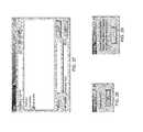
- FIG. 1is a side view of an automatic sensing power system with a detachable module in accordance with an embodiment of the present invention.
- FIG. 2is a top view of an automatic sensing power system with a detachable module in accordance with an embodiment of the present invention.
- FIG. 3is a side view of an automatic sensing power system in accordance with an embodiment of the present invention.
- FIG. 4is a diagram of an automatic sensing power system communicating with one or more electrical devices and an electrical supply in accordance with an embodiment of the present invention.
- FIG. 5is a block diagram of an automatic sensing power system in accordance with an embodiment of the present invention.
- FIG. 6is a block diagram of another automatic sensing power system in accordance with an embodiment of the present invention.
- FIG. 7is a block diagram of another automatic sensing power system in accordance with an embodiment of the present invention.
- FIG. 8is a block diagram of another automatic sensing power system in accordance with an embodiment of the present invention.
- FIG. 9is a block diagram of another automatic sensing power system communicating with a computing device and an electrical device in accordance with an embodiment of the present invention.
- FIG. 10is a block diagram of another automatic sensing power system in accordance with an embodiment of the present invention.
- FIG. 11is a block diagram of another automatic sensing power system in accordance with an embodiment of the present invention.
- FIG. 12is a side view of another automatic sensing power system with a detachable module in accordance with an embodiment of the present invention.
- FIG. 13is a top view of another automatic sensing power system with a detachable module in accordance with another embodiment of the present invention.
- FIG. 14is a side view of another automatic sensing power system in accordance with an embodiment of the present invention.
- FIG. 15is a top view of a line-cord automatic sensing device in accordance with an embodiment of the present invention.
- FIG. 16is a top view of another line-cord automatic sensing device with a connector and adaptors in accordance with an embodiment of the present invention.
- FIG. 17is a top view of other line-cord automatic sensing devices with connectors and DC adaptors in accordance with an embodiment of the present invention.
- FIG. 18is a front view of rack/cabinet mount automatic sensing devices in accordance with an embodiment of the present invention.
- FIG. 19is a front view of a modular power receptacle in a modular wall unit in accordance with an embodiment of the present invention.
- FIG. 20is a front view of a modular wall unit with modular automatic sensing power system receptacles in accordance with an embodiment of the present invention.
- FIG. 21is a front view of modular automatic sensing power system receptacles in accordance with an embodiment of the present invention.
- FIG. 22is a front view of modular automatic sensing power system receptacles in accordance with an embodiment of the present invention.
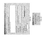
- FIGS. 23-43are screen views of a user interface used with an automatic sensing power system in accordance with an embodiment of the present invention.
- an automatic sensing power system (ASPS) componentis embedded in an electronic device, such as a laptop computer, and a power delivery component resides in an ASPS, such as a power strip or a receptacle.
- the laptopupon connection to the ASPS, the laptop communicates its power requirements to the ASPS via a power cord.
- the ASPSprocesses the request and supplies the appropriate power.
- Inexpensive low voltage electrical cords and modular adaptersreplace the wall-bricks typically supplied with cell and desk phones, personal digital assistants (PDAs), computers, mobile phones, digital cameras, cordless drills, fax machines, and other electrical devices.
- PDAspersonal digital assistants
- the ASPSis programmable and upgradeable.
- the ASPSsolves many problems currently encountered by home, office, and industrial consumers.
- the ASPScouples with single and multi-receptacle plug-in and hard-wired surge suppression devices, AC/DC power converters and transformers, and a wide-range of electronic and electrical appliances, tools, and devices.
- the ASPSeliminates wall-bricks by placing modular DC receptacles in a power system.
- the power systemhas AC and DC receptacles in one unit, thereby eliminating the need for multiple power strips.
- the power systemincludes communication and networking interfaces and systems over which communications may be transmitted, such as through Bluetooth, Ethernet, Firewire, and/or a USB connection.
- the ASPSincludes expanded data line protection, such as for cable, DSL, Ethernet, and modem protection.
- the ASPSintegrates gateway, network, and router capabilities. Another embodiment incorporates data communication over a broadband connection.
- electronic devicescommunicate with and through the power system via a DC connector or an AC connector.
- the ASPSincludes a line-cord device with a detachable wall plug device. Once detached, the wall-plug device can be moved between rooms or offices or taken on the road to replace wall-bricks.
- FIGS. 1-3depict an exemplary embodiment of an automatic sensing power system (ASPS).
- the ASPS 102includes a line-cord device 104 and a detachable wall plug device 106 .
- the line-cord device 104has a housing 108
- the detachable wall plug device 106has a housing 110 .
- the ASPS 102may be only a wall plug device, only a line-cord device, or a combination thereof.
- the ASPS 102also may be embodied in other forms, such as a modular wall plug permanently installed or removably installed in place of a wall receptacle, an alternating current (AC) wall receptacle, or another AC or direct current (DC) device.
- ACalternating current
- DCdirect current
- the ASPS 102may be incorporated in, for example, an electronic device, such as a computer, a laptop computer, a pocket PC, a personal digital assistant (PDA), a mobile phone, a recording device, or another electrical device.
- an electrical devicemeans a device that operates using electricity, including AC and/or DC electricity.
- electrical devicesmay use a portion of the ASPS systems identified below, including those electrical devices previously listed and other electrical devices.
- the line-cord device 104includes one or more AC receptacles 112 - 126 .
- Each AC receptacle 112 - 126includes a power control/indicator 128 - 142 , such as a physical or logical on/off switch used to enable or disable power flow to the associated AC receptacle 112 - 126 .
- the power control/indicators 128 - 142are lighted switches.
- the lighted switchesare lighted when power is enabled to the AC receptacle, and not lighted when power is not enabled to the receptacle.
- the power control/indicator 128 - 142is only an indicator, such as a light, and is not used to enable or disable power to the associated receptacle 112 - 126 .
- a processor within the ASPS 102may be used to enable or disable power to a receptacle, and the power control/indicator 128 - 142 indicates whether or not power is enabled or disabled for that receptacle.
- the power control/indicator 128 - 142is configured to enable and disable power to the associated receptacle, and the power control/indicator includes an indicator, such as a light, to indicate whether power is enabled for the receptacle either by the physical power control or by a processor or other system or method.
- the line-cord device 104also includes one or more automatic sensing (AS) DC receptacles 144 - 148 .
- ASautomatic sensing
- the AS DC receptacles 144 - 148may be used by devices for which the power requirements, including voltage and/or amperage requirements, will be automatically determined. The power requirements for the electrical device connected to the AS DC receptacles 144 - 148 then will be provided to the electrical device, as will be explained more completely below.
- the AS DC receptacles 144 - 148also have an associated power control/indicator 150 - 154 such as a physical or logical on/off switch used to enable or disable power flow to the associated DC receptacle 144 - 148 .
- the power/control indicators 150 - 154are lighted switches.
- the lighted switchesare lighted when power is enabled to the DC receptacle, and not lighted when power is not enabled to the receptacle.
- the power control/indicator 150 - 154is only an indicator, such as a light, and is not used to enable or disable power to the associated receptacle 144 - 148 .
- a processor within the ASPS 102may be used to enable or disable power to a receptacle, and the power control/indicator 150 - 154 depicts whether or not power is enabled or disabled for that receptacle.
- the power control/indicator 150 - 154is configured to enable and disable power to the associated receptacle, and the power control/indicator includes an indicator, such as a light, to indicate whether power is enabled for the receptacle either by the physical power control or by a processor or another system or method.
- the line-cord device 104also has a main power control/indicator 156 .
- the main power control/indicator 156is used to enable or disable power to the line-cord device 104 .
- the main power control/indicator 156includes a fuse device configured to disable power to the line-cord device 104 if power to the line-cord device exceeds selected voltage and/or selected amperage requirements.
- the main power/control indicator 156includes a surge protection device and/or other voltage and/or amperage protection devices.
- the ASPS 102also includes an electrical connector 158 configured to transfer power from an electrical supply to the ASPS 102 .
- the electrical connector 158also is configured to communicate data to and from the ASPS 102 .
- the ASPS 102includes a reset control 160 .
- the reset control 160is used to reset the ASPS 102 , in some instances, if a fuse or other device in the ASPS disables power to the ASPS.
- the ASPS 102includes a data in port 162 and/or a data out port 164 .
- the data ports 162 - 164are used to communicate data to and from the ASPS 102 , such as to a computing device, another data device, or another electrical device.
- the ASPS 102may use one or more communication protocols to transfer data to and from the ASPS.
- the ASPS 102includes a phone in port 166 and/or a phone out port 168 .
- the phone ports 166 - 168are used to communicate voice and/or data communications over a telephone or telephone-related communication device.
- the ASPS 102includes a data communication port 170 .
- the data communication port 170is used to communicate process data, control data, control instructions, update data, electrical device data, and other data with a processing device, a computing device, or another device.
- the data communication port 170is a universal serial bus (USB) port.
- other data communication connectorsmay be used.
- other data communication connections 172 and 174are used to communicate data to and from the ASPS 102 in various formats and using various protocols.
- the data connections 172 - 174include one or more cable ports, such as an in and out cable connection.
- Other types of data connections, networking connections, device connections, and/or device controllersmay be used.
- the detachable wall plug device 106includes AS DC receptacles 176 - 180 .
- the AS DC receptacles 176 - 180have an associated power control/indicator 182 - 186 .
- the AS DC receptacles 176 - 180 and the power control/indicators 182 - 186are the same as those described above.
- the detachable wall plug device 106also includes one or more electrical connectors 188 - 190 , such as module plugs, used to transfer power to the wall plug device.
- the electrical connectors 188 - 190connect to receiving connectors 192 - 194 in the line-cord device 104 .
- AC and/or DC poweris transmitted from the line-cord device 104 to the wall plug device 106 via the electrical connectors 188 - 190 and the receiving connectors 192 - 194 .
- communicationsincluding control instructions and/or data, are transmitted from the line-cord device 104 to the wall plug device 106 via the electrical connectors 188 - 190 and the receiving connectors 192 - 194 .
- one or more electrical connectorsmay be used.
- a standard 3-prong wall plugis depicted in FIGS. 1 and 2 , other electrical connectors may be used.
- the wall plug device 106includes a fuse device. In another embodiment, the wall plug device 106 includes a surge protection device and/or other voltage and/or amperage protection devices. In another embodiment, the wall plug device 106 includes a reset control.
- the ASPS 102includes a grounded indicator 196 and/or a protected indicator 198 .
- the grounded indicator 196indicates that the ASPS 102 is properly grounded to an electrical supply, such as to an AC receptacle. Therefore, the ASPS 102 should provide properly grounded electrical connections for electrical devices connected to the ASPS.
- the ASPS 102also may include a protected indicator 196 in other embodiments.
- the protected indicator 198indicates that surge protection and/or noise filtration systems and/or circuits are functional.
- the wall plug device 106includes a grounded indicator and/or a protected indicator.
- FIG. 4depicts an exemplary embodiment in which an ASPS 102 A communicates with one or more electrical devices 402 , including a computer 404 , a PDA 406 , a mobile phone 408 , and/or another electrical device, via an electrical connection 410 and/or a data communication connection 412 .
- the electrical connection 410 and/or the data communication connection 412are depicted as logical connections.
- the data communication connection 412is optional for some embodiments.
- the electrical connection 410 and/or the data communication connection 412both may use a single physical connection over which both power and data communications are transmitted.
- the electrical connection 410 and/or the data communication connection 412may use one or more physical connections.
- the ASPS 102 Aalso is connected by a connection 414 to a power system 416 and/or a communication system 418 .
- the power system 416is a power source for AC power.
- the ASPS 102 Acommunicates both power and data over the same connection 414 to the power system 416 .
- the power system 416includes one or more of a private power system and/or a public power system.
- data communicationsare transferred to other electrical devices, such as to communications devices or computers, via the power system 416 .
- data communicationsare transmitted to other electrical devices, such as communication devices and/or computers, via the communication system 418 .
- the electrical connection 410is an AC connection. In another example, the electrical connection 410 is a DC connection. In another embodiment, the electrical connection 410 is a two-wire DC cord with a modular connector on one end and a barrel connector on the other end. In another embodiment, the electrical connection 410 is a two-wire DC cord with a modular connector on one end and configured to accept one or more adaptive connectors on the other end.
- connection 414is connected to an electrical supply, such as an AC receptacle in a home, office, or business, to a private or public power system.
- connection 414 to the electrical supplyconnects to a public electrical power grid.
- Private circuitsgenerally connect to the electrical grid via a service entrance panel or subpanel device that may or may not require the AS communication interfaces described herein.
- an automatic sensing (AS) processing systemresides on the ASPS 102 A.
- an AS processing systemresides on the electrical device 402 .
- an AS processing systemdoes not reside on the electrical device 402 .
- the electrical device 402includes one or more of an Ethernet device, a cable device, a digital subscriber line (DSL) device, a satellite device, a dial-up device, an internet protocol (IP) device, or another device configured to communicate data, including voice communications converted to data and transferred as data via the connection 414 .
- the data communicationsare transferred via the power system 416 and/or the communication system 418 to another electrical device, such an Ethernet device, a cable device, a DSL device, a satellite device, a dial-up device, an IP device, or another device configured to transmit or receive communications.
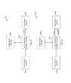
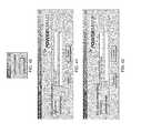
- FIG. 5depicts an exemplary embodiment of an automatic power system (APS).
- the APS 502 of FIG. 5includes an automatic sensing power system (ASPS) 102 B, an electrical supply 504 , an electrical device 506 , and a computing device 508 .
- the ASPS 102 Bis used to automatically determine the power requirements of the electrical device 506 , including voltage and/or amperage requirements, and supply the appropriate power to the electrical device.
- the electrical device 506does not have a power converter. Instead, the electrical device 506 includes a simple electrical connector between the ASPS 102 B and the electrical device.
- the electrical connectoris not a bulky power converter, such as a wall brick.
- the connectormay be a standard power conducting wire, such as those used for a laptop computer, a PDA, a mobile telephone, or another electrical device (without the power converter).
- the ASPS 102 Breceives power from the electrical supply 504 . Upon determining the power requirements, the ASPS 102 B supplies the correct power to the electrical device 506 .
- the ASPS 102 Bcommunicates with the computing device 508 .
- the computing device 508may be a computing device, data device, or another device configured to communicate with the ASPS 102 B.
- the computing device 508receives status data from the ASPS 102 B, including faults, breakdowns in processes, if any, surge identifications, and other status information.
- the ASPS 102 Breceives data from the computing device 508 .
- the ASPS 102 Breceives control data, such as configuration data, from the computing device 508 .
- a useruses the computing device 508 to load the power requirements of the electrical device 506 to the ASPS 102 B.
- the ASPS 102 Bstores the power requirements and uses the power requirements to provide the appropriate power levels, including voltage and/or amperage levels, to the electrical device 506 .
- the ASPS 102 Breceives data from the computing device 508 .
- the computing device 508is configured to transmit power requirements for the electrical device 506 to the ASPS 102 B.
- the ASPS 102 Bis configured to assign a particular receptacle, such as a particular DC or a particular AC receptacle, to the electrical device 506 .
- a usermay plug the electrical device 506 into a particular receptacle in the ASPS 102 B, and the power requirements will be transmitted to the electrical device 506 .
- the computing device 508is configured to enable the particular receptacle for the electrical device 506 .
- the computing device 508also is configured to disable one or more other receptacles, including one or more other AC receptacles and/or DC receptacles.
- disabling one or more receptaclesprovides a safety feature so that the electrical device 506 is not inadvertently plugged into a receptacle with the wrong power requirements, which may result in damaging the electrical device.
- an indicator lightmay indicate whether the receptacle is enabled or disabled to receive power and/or to transmit power to an electrical device.
- the ASPS 102 Bmay receive configuration data and/or control data to configure one or more receptacles.
- the ASPS 102 Bmay configure a first receptacle for a mobile telephone and a second receptacle for a computer.
- the first receptaclewould provide the correct power requirements to the mobile telephone
- the second receptaclewould provide the correct power requirements to the computer.
- the electrical device 506does not require an AS processing system, as described more completely below.
- This embodimentprovides flexibility to the user for devices not having the AS processing system.
- the configuration data and/or control datamay be provided to the ASPS 102 B in a variety of ways.
- the ASPS 102 Breceives configuration data identifying a model of a particular electrical device 506 , such as a device name and/or a model name or number or another identifier.
- data identifying particular electrical devices and their power requirementsreside on the ASPS 102 B.
- the ASPS 102 Bperforms a search, look up, or other process to identify the particular electronic device model and its power requirements from the data stored on the ASPS. The ASPS 102 B then can provide the correct power to the electrical device 506 .
- the ASPS 102 Bis configured to receive the particular power requirements, including voltage and/or amperage requirements, directly from the computing device 508 .
- the ASPS 102 Bis not required to perform a search, look up, or other processing operation to identify a particular electrical device's power requirements.
- the ASPS 102 Bconfigures a particular receptacle for the power requirements.
- FIG. 6depicts another exemplary embodiment of an APS 502 A.
- the electrical device 506 Aincludes an AS processing system.
- poweris transmitted from the ASPS 102 C to the electrical device 506 A.
- datais communicated between the ASPS 102 C and the electrical device 506 A.
- the power and the datamay be transmitted over the same physical connection, one physical connection for the power and another physical connection for the data, or multiple physical connections for the power and/or data.
- the ASPS 102 Cidentifies that an electrical device 506 A has been plugged into one of the receptacles. This identification may be made through hardware, software, firmware, or other methods.
- the electrical device 506 Amakes a circuit when the electrical device is plugged into the receptacle.
- the electrical device 506 Acauses the receptacle to transmit a signal when the electrical device is plugged into the receptacle.
- the electrical device 506 Agenerates a power request upon being connected to the receptacle.
- the requestincludes an identification of the particular electrical device.
- the requestincludes specific power requirements for the electrical device 506 A.
- the ASPS 102 Creceives the request and determines the power requirements for the electrical device 506 A. In one example, the ASPS 102 C identifies the particular electrical device 506 A and searches its data, such as through a look up, a search, or other determination, to identify the power requirements for the electrical device 506 A. The ASPS 102 C provides the appropriate power, including the appropriate voltage and amperage, to the electrical device 506 A.
- the ASPS 102 Creceives a request for power from the electrical device 506 A.
- the requestincludes the specific power requirements.
- the ASPS 102 Cis not required to perform a look up, search, or other determination to identify the power requirements for the electrical device 506 A.
- the ASPS 102 Cprovides the power to the electrical device 506 A according to the power requirements.
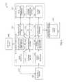
- FIG. 7depicts an exemplary embodiment of one or more processes occurring in the ASPS 102 D, the electrical device 506 B, and the electrical device 506 C.
- the ASPS 102 Dcommunicates with a computing device 508 B, and the ASPS 102 D receives power from the electrical supply 504 .
- the ASPS 102 Dhas an AS processing system 702 .
- the AS processing system 702controls the operations of the ASPS 102 D, including data storage, power conversion, enabling and/or disabling receptacles, generating the correct power to each receptacle, communicating with electrical devices 506 B and 506 C, and communicating with the computing device 508 B.
- the AS processing system 702stores data in, and retrieves data from, the storage device 704 .
- the storage device 704may include, for example, RAM, ROM, EPROM, EEPROM, Flash storage, or another storage device.
- the AS processing system 702also processes communications received from the electrical device 506 B via the AS communication interface 706 .
- the AS processing system 702determines what action to the take based upon the communication from the electrical device 506 B.
- the AS processing system 702also may transmit data and/or other communications to the electrical device 506 B via the AS communication interface 706 B.
- the AS processing system 702controls conversion of power at the power converter 708 .
- the AS processing system 702transmits control signals to the power converter 708 to control the power conversion and subsequent output of the converted power to one or more receptacles.
- the AS processing system 702is configured to control at which receptacle the power is output from the power converter 708 .
- the AS processing system 702may transmit a control signal to the power converter 708 requiring the power converter to output power to a selected receptacle.
- the power converter 708is hard wired to one or more receptacles, and the AS processing system 702 controls hard wired switches from the power converter to one or more receptacles.
- the power converter 708may otherwise output power to particular receptacles in response to control signals from the AS processing system 702 .
- the power converter 708receives power from the power input interface 710 .
- the power input interface 710receives power from the electrical supply 504 .
- the power converter 708includes voltage and/or amperage protection and/or surge protectors. In another embodiment, voltage and/or amperage protection and/or surge protectors are configured between the power output interface 712 and the power converter 708 and/or the AS processing system 702 .
- the AS processing system 702also controls the receptacles in the power output interface 712 .
- the power output interface 712includes one or more AC receptacles and/or one or more DC receptacles.
- the power output interface 712may include one or more power control/indicators, such as those identified in FIGS. 1-3 .
- the power control/indicatorsmay be controlled by the AS processing system 702 or otherwise. Alternately, the power control/indicators may be hard wired to one or more receptacles. In one example, the power control/indicators may indicate that power is enabled or disabled for a particular receptacle based upon power being transferred to the control/indicator. Other examples exist. In another example, the power control/indicator is a physical switch used to disable or enable power to a particular output, regardless of any control processing by the AS processing system 702 .
- the AS processing system 702also may transmit data to, and receive data from, a computing device 508 B or another device via the communication interface 714 .
- the communication interface 714may be used to transmit and/or receive control data, configuration data, status data, or other data.
- the AS processing system 702transmits and/or receives configuration data from the computing device 508 B via the communication interface 714 .
- the AS processing system 702transmits and/or receives configuration data from the computing device 508 B via the communication interface 714 and stores the configuration data in the storage device 704 .
- the configuration datamay be, for example, search data or other data used by the AS processing system 702 to identify power requirements for one or more electrical devices.
- the AS processing system 702also may transmit and/or receive other data, such as communication data, application data, video, voice communications, and other communications via the communication interface 714 to the computing device 508 B or through the electrical supply 504 .
- the electrical supply 504includes a power supply grid.
- the AS processing system 702transmits data via the communication interface 714 to the electrical supply 504 for further communication to another electrical device.
- the AS processing system 702transmits data via the communication interface 714 to the computing device 508 B.
- the data transmitted by the AS processing system 702 via the communication interface 714may be configuration data, status data, or other data used for the operation of the electrical device 506 B or 506 C or other information regarding the electrical devices.
- the datamay be used by a user of the computing device 508 B or another user.
- the AS processing system 702also may transmit data to, and receive data from, a computing device 508 B or another device via a user interface 716 .
- the user interface 716generates data for display by the computing device 508 B or another device.
- the user interface 716may be used to transmit and/or receive control data, configuration data, status data, or other data.
- the user interface 716resides on the ASPS 102 D and generates data for display by the electrical device 506 B.
- the user interface 716resides on the electrical device 506 B, and the ASPS 102 D communicates with the user interface so the user interface can display data and enter control processes and operations, such as selecting a particular voltage for a particular receptacle.
- the communication interface 706 and the communication interface 714are a single interface. In other examples, the communication interface 706 , the communication interface 714 , and/or the user interface 716 are a single interface.
- the electrical device 506 Bhas an electrical device automatic sensing (EDAS) processing system 718 and a power input interface 720 .
- the EDAS processing system 718communicates with the ASPS 102 D via the AS communication interface 706 .
- the EDAS processing system 718includes a processor.
- the EDAS processing system 718includes a storage device, such as an EPROM, EEPROM, Flash storage, or other storage.
- the EDAS processing system 718is configured with hardware, firmware, and/or software configured to communicate with the ASPS 102 D and/or otherwise configure, control, transmit, receive, and/or process communications related to power requirements, statistics, and/or operational requirements of the electrical device 506 B.
- the EDAS processing system 718generates a request for power to the ASPS 102 D via the AS communication interface 706 . In another embodiment, the EDAS processing system 718 receives a communication requesting whether or not the electrical device 506 B is to receive power. In another embodiment, the EDAS processing system 718 processes instructions for transmitting power requirements to the ASPS 102 D or for receiving information regarding power requirements of the electrical device 506 B and the provision of power to the electrical device from the ASPS 102 D.
- the power input interface 720receives power from the ASPS 102 D via the power output interface 712 .
- the power input interface 720may be hardware, such as a plug and/or cord, and/or another device.
- the electrical device 506 Cdoes not include an EDAS processing system. In this embodiment, data is not communicated between the electrical device 506 C and the ASPS 102 D. In this embodiment, the electrical device 506 C receives power at the power input interface 722 from the ASPS 102 D via the power output interface 712 .
- the computing device 508 Bincludes a configuration system used to configure the ASPS 102 D.
- the computing device 508 Bincludes a user interface (UI) used to configure power requirements for particular electrical devices, power requirements or other configurations for particular AC and/or DC receptacles, operational parameters for the ASPS 102 D, and/or other processes of the ASPS 102 D.
- UIuser interface
- the UIenables a user to configure particular receptacles on the ASPS 102 D for particular electrical devices.
- the UIpresents a simple screen or other output to the user, such as with radio buttons to enable or to disable particular receptacles.
- a usermay use the UI to program a DC receptacle for a mobile telephone by setting the voltage and/or amperage requirements of the mobile telephone for a selected receptacle.
- the usermay use the GUI to program a second DC receptacle for a PDA by setting the voltage and/or amperage requirements of the PDA for a selected receptacle.
- the usermay select an identification of the electrical device from a menu or other interface. The electrical device then may be assigned to a particular receptacle.
- the particular receptacle with the associated electrical devicemay be enabled or disabled using a radio button or other entry on the UI.
- an enable and disable buttonis generated for the first receptacle.
- an enable and disable buttonis generated for the second receptacle.
- the ASPSretains the configuration data.
- the ASPS 102 Dmay be reset by the computing device 508 B.
- the ASPS 102 D configurationmay be reset by a reset button, such as the reset button depicted in FIG. 1 .
- the configuration of the ASPS 102 Dmay be reset upon removing power from the device. Other examples exist.
- FIG. 8depicts an exemplary embodiment of an ASPS 102 E communicating with the electrical device 506 D.
- the ASPS 102 Ehas a communication interface 802 through which it communicates to a communication interface 804 of the electrical device.
- the AS processing system 702 Acontrols transmission of communications from, and reception of communications at, the communication interface 802 .
- the communication interface 706 and the communication interface 714are a single interface. In other examples, the communication interface 706 , the communication interface 714 , the user interface 716 , and/or the communication interface 802 are a single interface.
- communications normally transmitted to and from the electrical device 506 D via an Ethernet connection, a cable connection, a DSL connection, a dial-up connection, an IP connection, or another type of connection through which other data may be communicatedare transmitted to the ASPS 102 E for further transmission and from the ASPS to the electrical device.
- the communications being transmitted between the electrical device 506 D and the ASPS 102 Emay occur via one or more physical connections.
- the power transmitted from the ASPS 102 E to the electrical device 506 Dmay be provided over the same physical connection or another physical connection.
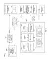
- FIG. 9depicts an exemplary embodiment of another ASPS 102 F communicating with an electrical device 506 E and a computing device 508 D.
- the ASPS 102 Fincludes an AS processing system 702 B.
- the AS processing system 702 Boperates with a power data system 902 , a data update and device control process 904 , and a communication system 906 .
- the power data system 902has data identifying the power requirements for one or more electrical devices.
- the power data system 902includes a voltage and/or amperage database that identifies the voltage and/or amperage requirements for one or more electrical devices.
- the voltage and/or amperage databasemay be used with a look up or other search process by the AS processing system 702 B to identify the power requirements for an electrical device.
- the power data system 902may include other power related data, including configuration data and other operational data.
- the data update and device control process 904is used to automatically update information stored in the power data system 902 .
- the data update and device control process 904includes an automatic database update process used to automatically receive database updates from the computing device 508 D and to automatically store the updated data in the power data system 902 .
- the communication system 906may include a communication interface to the computing device 508 D, a communication interface to the electrical device 506 E, and/or another system configured to receive and/or transmit communications, including instructions and data.
- the communication system 906may include one or more different types of physical connections and/or ports by which communications are received or transmitted.
- the communication system 906also may operate according to one or more communication protocols to receive and/or transmit communications.
- the computing device 508 Dincludes a processor 908 used to control the processes in the computing device.
- the processor 908controls storage of data in, and retrieval of data from, the data storage device 910 .
- the processor 908also receives communications from, and transmits communications to, the communication system 912 .
- the processor 908also receives data from, and transmits data to, the update system 914 .
- the update system 914may include an automated data update process 916 and a manual update process 918 .
- the automated data update process 916is configured to automatically update data, including configuration data, power requirements, and other data, for the ASPS 102 F.
- the manual data update process 918is configured to enable a user to manually update data, including configuration data, power requirements, and other data, to the ASPS 102 F.
- the processor 908controls generation of data to the display 920 , such as data for a GUI or another user interface. Additionally, the processor 908 receives data from an input device 922 , such as a keyboard, a mouse, a pointer, or another input device. The processor 908 also outputs data to other output devices 924 , such as a printer, another electrical device, or another device.
- an input device 922such as a keyboard, a mouse, a pointer, or another input device.
- the processor 908also outputs data to other output devices 924 , such as a printer, another electrical device, or another device.
- the computing device 508 Denables a user to configure the ASPS 102 F, including one or more AC and/or DC receptacles on the ASPS 102 F.
- the configurationincludes enabling and disabling one or more receptacles and providing configuration data, including power requirements, to the ASPS 102 F for one or more receptacles in which one or more electrical devices will be plugged.
- the processor 908generates a GUI to the display 920 . In another embodiment, the processor 908 generates another user interface.
- the GUI or other user interfaceis used to display operational and event logging. In another embodiment, the GUI or other user interface is used to display device operational information and AC and/or DC receptacle controls.
- the electrical device 506 Econnects to the ASPS 102 F. Thereafter, the electrical device 506 E initiates an automatic power request upon the connection at step 926 .
- the ASPS 102 Freceives the request, processes the request, and automatically initiates the power supply to the electrical device 506 E at step 928 .
- systemincludes hardware, firmware, software, and/or other systems used to perform the functional and/or component operations and/or requirements.
- interfaceincludes hardware, firmware, software, and/or other systems used to perform the functional and/or component operations and/or requirements.
- One or more interfaces and/or systemsmay be separated and/or combined in the above-descriptions. Physical and/or logical components may be combined and/or separated.
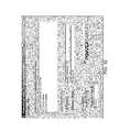
- FIG. 10depicts an exemplary embodiment of an ASPS 102 G.
- a processor 1002controls the operation of the ASPS 102 G.
- Poweris received at the ASPS 102 G from a power system 416 .
- the poweris received at a fuse 1004 .
- the powermay be received into the ASPS 102 G at a resetable switch 1006 , at an on/off switch 1008 , or at another component.
- the fuse 1004enables power to flow from the power system 416 to the ASPS 102 G.
- the fuse 1004terminates the flow of power into the ASPS 102 G when the amperage level or another power level reaches an upper limit.
- the fuse 1004opens the circuit between the power system 416 and the resetable switch 1006 , or other components of the ASPS 102 G, if the resetable switch is not present or when the current from the power system 416 is approximately at or exceeds 30 amps, thereby terminating the flow of electricity to the ASPS 102 G.
- the fuse 1004is replaced after the fuse opens the circuit between the power system 416 and the resetable switch 1006 or other components.
- the fuse 1004is optional in some embodiments.
- the resetable switch 1006temporarily terminates the circuit between the power system 416 and the on/off switch 1008 or other components of the ASPS 102 G if the on/off switch is not present. In one example, if the on/off switch 1008 is not present, the resetable switch 1006 temporarily terminates the circuit between the power system 416 and the optical relay 1010 and the AC to DC switching regulator 1012 .
- the resetable switch 1006can be reset, such as by a user or automatically by another method, to close the circuit and enable power transmission to the components of the ASPS 102 G.
- the resetable switch 1006is a circuit breaker configured to open the circuit when the current level from the power being drawn from the power system 416 is approximately at or exceeds 15 amps.
- the resetable switch 1006is optional in some embodiments.
- the on/off switch 1008enables a user to manually turn power on and off for the ASPS 102 G.
- the on/off switch 1008may be a toggle switch, a push switch, an electronic and/or software driven switch, or another type of switch. It will be appreciated that the on/off switch 1008 may be located logically or physically in another location in the ASPS 102 G, such as before or after the fuse 1004 or the resetable switch 1006 .
- the on/off switch 1008is optional in some embodiments.
- the optical relay 1010isolates the incoming AC power from the processor 1002 and enables the processor to control turning AC power on or off for one or more of the AC receptacles 1014 .
- the optical relay 1010isolates the received AC power and the transmitted AC power from connections from the processor 1002 .
- the optical relay 1010receives one or more signals from the processor 1002 . Based upon the one or more signals, the optical relay 1010 connects AC power to one or more of the AC receptacles 1014 . In one embodiment, the optical relay 1010 connects AC power to one selected AC receptacle. In another embodiment, the optical relay 1010 connects AC power to N selected AC receptacles out of M possible AC receptacles, where N is a number greater than or equal to one, and M is a number greater than or equal to one.
- the optical relay 1010is a TRIAC. In other embodiments, the optical relay 1010 is another transistor device. In other embodiments, the optical relay 1010 is another type of relay configured to isolate the processor 1002 from the incoming AC power and the outgoing AC power to the AC receptacles 1014 .
- the optical relay 1010is optional in some embodiments.
- the AC to DC regulator 1012receives AC power and converts the AC power to DC power.
- the converted DC poweris transmitted to the linear regulator 1016 and to the DC to DC regulator 1018 .
- the AC to DC regulator 1012converts 120 volt AC (VAC) power to 24 volt DC (VDC) power.
- the AC receptacles 1014are configured to transmit power from the ASPS 102 G to one or more electrical devices connected to the AC receptacles.
- the AC receptacles 1014include one or more AC receptacles. In one embodiment, a single AC receptacle is included in the ASPS 102 G. In another embodiment, 8 AC receptacles are included in the ASPS 102 G. In another embodiment, N AC receptacles are included in the ASPS 102 G, where N is a number greater than or equal to one.
- the AC receptacles 1014include one or more 3-prong AC receptacles. In another embodiment, the AC receptacles 1014 include one or more 2-prong AC receptacles. Other embodiments include other types of AC receptacles.
- the AC receptacles 1014are optional in some embodiments.
- an optional switch(not shown) is included between the optical relay 1010 and the AC receptacles 1014 .
- the optional switchenables a user to turn a selected one or more of the AC receptacles 1014 on or off.
- each optional switchincludes one of the indicators 1024 .
- the linear regulator 1016converts the DC power received from the AC to DC regulator 1012 to DC voltages required by other components in the ASPS 102 G.
- the linear regulator 1016provides DC voltage to integrated circuits, linear components, and other components in the ASPS 102 G.
- the linear regulator 1016down converts the 24 VDC voltage received from the AC to DC regulator 1012 and transmits the down-converted DC voltage to the processor 1002 , the optical relay 1010 , the modulator 1020 , the memory 1022 , the indicators 1024 , the reset controller 1026 , and the communication system 1028 .
- the linear regulator 1016outputs 5 volts DC to one or more components of the ASPS 102 G.
- the linear regulator 1016outputs N volts DC to one or more components of the ASPS 102 G, where N is a number greater than or equal to 0.001.
- the DC to DC regulator 1018provides DC power to the DC receptacles 1030 at one or more voltage levels.
- the DC to DC regulator 1018is an adjustable switching regulator configured to convert the 24 VDC incoming power to one or more output DC voltages.
- the DC to DC regulator 1018is a synchronous adjustable switching regulator.
- the DC to DC regulator 1018receives one or more signals from the processor 1002 .
- the DC to DC 1018sets the output DC voltage based upon the one or more signals received from the processor 1002 , and outputs the set voltage to one or more selected DC receptacles 1030 .
- the processor 1002digitally adjusts the output of the DC to DC regulator 1018 and configures the DC to DC regulator to output the selected DC voltage to a selected DC receptacle.
- the DC to DC regulator 1018may receive a first signal from the processor 1002 from which the DC to DC regulator configures a first output DC voltage for 20 VDC and 4.5 amps.
- the DC to DC regulator 1018receives a signal from the processor 1002 from which the DC to DC regulator configures an output DC voltage to a selected DC receptacle for 7.5 VDC and 1 amp. In another example, the DC to DC regulator 1018 receives a signal from the processor 1002 from which the DC to DC regulator 1018 configures an output DC voltage for a selected DC receptacle for 3.7 VDC and 340 milli-amps. Other examples exist.
- the modulator 1020transmits communications to and receives communications from one or more DC receptacles 1030 .
- the modulator 1020enables the ASPS 102 G to transmit communications to an electrical device and receive communications from an electrical device over DC power carrying wire or other cable via the DC receptacles 1030 .
- the modulator 1020also transmits communications to and receives communications from the processor 1002 .
- the modulator 1020modulates communications received from the processor 1002 for transmission to the DC receptacles 1030 .
- the modulator 1020also demodulates communications received from the DC receptacles 1030 for transmission to the processor 1002 .
- the modulator 1020modulates and demodulates communications using voltage modulation.
- the modulator 1020modulates the on and off states of a DC voltage to serially transmit data packets.
- the modulator 1020receives voltage modulated data packets and detects the modulated data packets.
- the modulator 1020reassembles the data packets to a digital form and transmits the digital data to the processor 1002 .
- the modulator 1020 or the processor 1002includes a voltage divider circuit that divides the voltage level of the received data to a lower range. An analog-to-digital converter then converts the divided-voltage into a digital format processable by the processor 1002 .
- one or more communications from the electrical device connected to the DC receptacle 1030includes an identification string or other identification in the communication.
- the identification stringis a series of ASCII characters that correspond to data or a data structure stored in the memory 1022 .
- the electrical device identification and/or the voltage codeare stored as data in the memory 1022 .
- one or more communicationsare transmitted from and received at the modulator 1020 serially.
- the communicationsare formatted using a hexadecimal format.
- one or more of the followingmay be transmitted: a request by the ASPS 102 G if an electrical device is present, an acknowledgment by the electrical device, a request for an identification code from the electronic device, an electronic device identification code, a request for a voltage code, an electrical device voltage code, an instruction to an electrical device to enable DC power for itself, a request from the ASPS for data, an electrical device data download, and other communications.
- one or more of the previously identified communicationsinclude ASCII characters transmitted via the hexadecimal format.
- the modulator 1020transmits and receives communications using frequency shift key modulation. In this embodiment, communications are transmitted and received using a higher bandwidth.
- the modulator 1020transmits and receives carrier signals that are superimposed onto the power generated from the DC to DC regulator 1018 through the DC receptacles 1030 .
- other types of modulation and/or communicationmay be used.
- the memory 1022includes RAM, Flash memory, EEPROM memory, and/or other memory.
- the memory 1022may be used, for example, to store data, data structures, operating parameters, and/or programming, including firmware, software, and other programming.
- the memory 1022stores data received from the processor 1002 .
- the memory 1022also retrieves data and transmits it to the processor 1002 .
- the memory 1022stores product specification data for one or more electrical devices.
- the product specification dataincludes names of one or more electrical devices, model numbers of one or more electrical devices, serial numbers of one or more electrical devices, a product description of one or more electrical devices, and customer numbers for one or more electrical devices. Other data may be included.
- the memory 1022includes data structures identifying voltage requirements for one or more electrical devices.
- the data structurealso includes a designation of the electrical device, such as a model name, a model number, a serial number, or another designation.
- the memory 1022includes data stored by the ASPS 102 G during the operation of the ASPS.
- This datamay include, for example, a voltage setting for a selected DC receptacle, another voltage setting for another selected DC receptacle, a voltage setting for an electrical device, another voltage setting for another electrical device, and other data.
- the ASPS dataalso may include event data, such as for power surges, selected settings for DC receptacles, states of the receptacles, critical events for the ASPS, including data identifying a blown fuse or a broken circuit, when an event occurred, and other data. Other examples exist.
- the memory 1022stores one-time variables and buffer data for the processor 1002 operations. In another embodiment, the memory 1022 includes non-volatile storage for the storage of programming that is executed by the processor 1002 . In another embodiment, the memory 1022 stores other non-volatile variable data, such as event data, data strings, voltage settings, and other product data.
- the indicators 1024indicate a status of one or more states and/or one or more operations for the ASPS 102 G. In one embodiment, the indicators 1024 indicate a status of one or more DC receptacles 1030 and/or one or more AC receptacles 1014 . In one example, the indicator is off, red, or green. If the indicator is off, the receptacle is not powered. If the indicator is green, the receptacle is powered and configured to output power to an electrical device. If the indicator is red, the receptacle is active and available to generate power to a connecting electrical device, but the receptacle is not yet generating power to the electrical device. If the indicator is red and green, an error condition exists.
- the indicators 1024receive one or more control signals from the processor 1002 and operate in accordance with the signals.
- a control signalcauses an indicator to enable a red or green indication.
- the indicators 1024are light emitting diodes (LEDs). In other embodiments, the indicators 1024 are other light emitting devices. In still other embodiments, the indicators are other types of indicating devices. The indicators 1024 are optional in some embodiments.
- the reset controller 1026resets the components on the ASPS 102 G.
- the reset controller 1026provides a memory address to the processor 1002 at which start-up programming is stored.
- the reset controller 1026resets one or more DC receptacles 1030 so that the DC receptacles and the DC to DC regulator 1018 are not set for particular DC output voltages.
- the reset controller 1026resets the AC receptacles 1014 .
- the reset controller 1026resets all logic components on the ASPS 102 G.
- the reset controller 1026is optional in some embodiments.
- the communication system 1028processes communications transmitted from, and communications received at, the communication interface 1032 .
- the communication system 1028formats communications to be transmitted from the ASPS 102 G in a format receivable by the receiving device.
- the communication system 1028formats communications received from a transmitting device connected to the ASPS 102 G so that the formatted communications are processable by the processor 1002 .
- the communication system 1028processes communications for various protocols.
- the communication system 1028processes universal serial bus (USB) based communications.
- USBuniversal serial bus
- the communication system 1028decodes USB data received via the communication interface 1032 and transmits the decoded data to the processor 1002 .
- These communicationsmay include, for example, control commands, data, and programming.
- the communication system 1028also receives communications from the processor 1002 and codes the communications for transmission as USB data via the communication interface 1032 . These communications may include, for example, control commands, data, and programming.
- the communication system 1028may be configured to transmit and receive communications via other protocols.
- the communication system 1028may be configured to transmit and receive communications as internet protocol (IP) packets, analog-based data such as voice data, digitized data, Ethernet-based data, and other types of communication system based data.
- IPinternet protocol
- analog-based datasuch as voice data, digitized data, Ethernet-based data, and other types of communication system based data.
- the communication system 1028is optional in some embodiments.
- the DC receptacles 1030are configured to transmit power from the ASPS 102 G to one or more electrical devices connected to the DC receptacles.
- the DC receptacles 1030include one or more DC receptacles.
- a single DC receptacleis included in the ASPS 102 G.
- N DC receptaclesare included in the ASPS 102 G, where N is a number greater than or equal to one.
- one or more of the DC receptacles 1030are barrel connectors.
- the barrel connectorincludes a ground pin and power pin.
- the DC receptacle in this embodimentis a female barrel connector and is configured to receive a male barrel connector.
- the barrel connectoralso includes a switch and/or switch detector configured to indicate when a mating barrel connector is connected to the barrel connector of the DC receptacle 1030 .
- the processor 1002receives a signal from the switch detector when a mating barrel connector is connected to the connector of the DC receptacle.
- the switch detectorhas a switch lead that is connected to a ground lead when no device is plugged into the barrel connector.
- the switch leadalso is connected to the processor 1002 , and a switch detector signal is transmitted via the switch lead to the processor.
- the processor 1002reads the switch detector signal as a logic 0, which corresponds to ground.
- the switch leadis disconnected from the ground lead.
- the processor 1002reads the switch detector signal as a logic 1, which indicates an electrical device is connected into the barrel connector of the DC receptacle.
- an optional switch(not shown) is included between the DC to DC regulator 1018 and the DC receptacles 1030 .
- the optional switchenables a user to turn a selected one or more of the DC receptacles 1030 on or off.
- each optional switchincludes one of the indicators 1024 .
- the communication interface 1032interfaces to one or more types of communication systems.
- the communication interface 1032is a USB interface.
- the communication interfaceis an RJ-11 or RJ-14 telephone jack interface.
- the communication interfaceis an RJ-45 connector.
- the communication interface 1032is an Ethernet-based interface.
- One or more of the previously referenced communication interfaces and/or one or more other interfacesmay exist in a single embodiment. Other examples exist.
- the communication interface 1032is optional in some embodiments.
- the processor 1002controls the operations of the ASPS 102 G.
- the processor 1002controls the on and off states of the AC receptacles 1014 by enabling and disabling the optical relay 1010 to connect and disconnect the AC input power for output to one or more AC receptacles.
- the processor 1002transmits one or more signals to the optical relay 1010 to make or break a connection for one or more of the AC receptacles 1014 .
- the processor 1002controls the on and off states of the DC receptacles 1030 .
- the processor 1002controls which DC receptacles 1030 will be enabled with DC power.
- the processor 1002determines the DC power level that will be output from the DC to DC regulator 1018 for each DC receptacle.
- the processor 1002transmits a signal to the DC to DC regulator 1018 identifying the DC power level to be output to each DC receptacle and enables the DC power output level for that DC receptacle.
- the processor 1002controls the transmission and reception of data to and from the modulator 1020 .
- the processor 1002receives data from the modulator 1020 and processes the data.
- the datamay include, for example, a specific or approximate DC voltage level required by an electrical device connected to one of the DC receptacles 1030 and/or an identification of the electrical device.
- the processor 1002determines the type of communication that will be made via the modulator 1020 .
- the processor 1002controls the modulation of the modulator 1020 so that communications are made in a format receivable by the electrical device connected to the DC receptacle 1030 .
- the processor 1002also controls demodulation of the modulator 1020 so that communications received from an electrical device are transmitted in a format receivable by the modulator 1020 and processable by the processor 1002 .
- the processor 1002controls the indicators 1024 .
- the processor 1002transmits one or more signals to one or more of the indicators 1024 for an indicator status.
- the indicators 1024are LEDs, and the processor 1002 enables a particular input to cause the LED to turn on. In another example, the processor 1002 enables another input of the LED to cause the LED to light a second color.
- the processor 1002controls start-up of the ASPS 102 G. In addition, upon receiving a reset signal from the reset controller 1026 , the processor 1002 retrieves the start-up programming from memory 1022 and resets the ASPS 102 G.
- the processor 1002processes communications received via the modulator 1020 and the communication system 1028 .
- the processor 1002also transmits communications via the modulator 1020 and the communication system 1028 .
- the processor 1002generates a user interface via the communication system 1028 for display, such as for display on a computer system with a monitor.
- the processor 1002transmits data to the computer system for display.
- the datamay include, for example, voltage levels required for a particular DC receptacle 1030 , instructions to enable a particular DC receptacle for a particular level, instructions to enable or disable one or more AC receptacles 1014 and/or DC receptacles 1030 , or other data.
- the user interfaceresides on a computer system that is communicating with the processor 1002 via the communication system 1028 and the communication interface 1032 .
- the processor 1002transmits data to the computer system for display by the user interface.
- the computer systemtransmits data received from the user interface to the processor 1002 for processing.
- the datamay include, for example, voltage levels required for a particular DC receptacle 1030 , instructions to enable a particular DC receptacle for a particular level, instructions to enable or disable one or more AC receptacles 1014 and/or DC receptacles 1030 , or other data.
- the processor 1002monitors the output from the DC to DC regulator 1018 to identify the actual or approximate actual voltage being generated from the DC to DC regulator to a selected DC receptacle 1030 .
- the raw analog voltage level generated by the DC to DC regulator 1018is used as a feedback signal and is input back to the processor 1002 .
- This feedback signalis indicated by the dashed-line between the processor 1002 and the DC to DC regulator 1018 in FIG. 10 .
- the processor 1002has a voltage divider that divides the feedback signal to a lower DC voltage range, such as between 0 volts and 5 volts, samples the divided feedback signal with an analog-to-digital converter, and uses the sampled feedback signal to determine if any adjustments must be made to the output of the DC to DC regulator 1018 to maintain the proper output DC voltage.
- the voltage divideris a circuit having two resistors.
- the processor 1002transmits an adjustment signal to the DC to DC regulator 1018 to adjust its output of a DC voltage for a particular DC receptacle 1030 .
- the adjustment signalis an analog output signal that is used to inject an offset into the DC to DC regulator 1018 .
- the degree of offsetis linearly related to the output DC voltage of the DC to DC regulator 1018 .
- the GainFactoris a gain specific to the DC to DC regulator 1018 , and its value depends upon the exact design of the DC to DC regulator.
- the Toleranceis a parameter used to express the production tolerance of each DC to DC regulator. Ideally, the Tolerance is 0.
- the feedback loop signalenables the processor 1002 to vary Vadjustment until Voutput is equal to the DC voltage required by the electrical device connected to the particular DC receptacle.
- the adjustment signalincludes a raw digital format, rather than an analog format. Other examples exist.
- the processor 1002when an electrical device is connected to one of the DC receptacles 1030 , the processor 1002 causes a minimal level of DC power to output from the DC to DC regulator 1018 to the DC receptacle.
- the minimal power levelis enough DC power to initiate operations of the electrical device, such as operation of the electrical device's processor, but not enough DC power to fully power the electrical device.
- the minimal power levelis low enough that it will not exceed power levels that may damage the electrical device.
- the minimal power levelenables the processor of the electrical device to communicate with the processor 1002 of the ASPS 102 G.
- the processor of the electrical devicethen is able to transmit the voltage requirements or the electrical device's identification to the processor 1002 of the ASPS 102 G.
- the processor 1002then configures the DC voltage level to be output from the DC to DC regulator 1018 to the DC receptacle 1030 in which the electrical device is connected and enables output of the DC power to that DC receptacle.
- FIG. 11depicts another exemplary embodiment of a ASPS 102 H.
- the ASPS 102 Hincludes DC receptacle 1 1030 A through DC receptacle N 1030 B.
- Each DC receptacle 1030 A- 1030 Bhas an associated detector 1102 - 1104 , such as a detector switch for the barrel connector described above. Other examples exist.
- Each detector 1102 - 1104is configured to enable a signal to the processor 1002 A identifying that an electrical device connector has been connected to the receptacle 1030 A- 1030 B.
- a modulator 1020 A- 1020 Bis configured to communicate between a respective DC receptacle 1030 A- 1030 B and the processor 1002 A.
- the processor 1002 Atransmits communications to the DC receptacles 1030 A- 1030 B via the modulator 1020 A- 1020 B and receives communications from the DC receptacles via the modulators.
- a low current driver 1106 and 1108 and a high current switch 1110 and 1112are associated with each DC receptacle 1030 A- 1030 B.
- the low current drivers 1106 and 1108receive DC power from the DC to DC regulator 1018 A- 1018 B at a low current level and/or a low voltage level.
- the low current drivers 1106 - 1108provide the DC power to the DC receptacles 1030 A- 1030 B.
- the low current driver 1106 - 1108is used to signal to the electrical device connected to the DC receptacle 1030 A- 1030 B that the processor 1002 A will transmit communications to, or receive communications from, the electrical device.
- a low current driver 1106 - 1108includes one or more resistors.
- the high current switches 1110 - 1112receive DC power from the DC to DC regulator 1018 A- 1018 B at a high current level and/or a high voltage level.
- the high current switches 1110 - 1112provide the DC power to the DC receptacles 1030 A- 1030 B.
- the DC power provided by the high current switch 1110 - 1112 to the DC receptacle 1030 A- 1030 Bis used to charge or otherwise power the electrical device connected to the DC receptacle.
- a high current switch 1110 - 1112includes a transistor or multiple transistors configured to receive DC power from the DC to DC regulator 1018 A- 1018 B and to receive an enable signal from the processor 1002 A. Upon receiving the enable signal from the processor 1002 A, the high current switch 1110 - 1112 transmits the DC power to the DC receptacle 1030 A- 1030 B.
- the processor 1002 A and the modulators 1020 A- 1020 Bare configured to communicate using voltage modulation.
- the modulator 1020 A- 1020 Btransmits communications to, and receives communications from, the DC receptacle 1030 A- 1030 B using a hexadecimal format.
- one or more communicationstransmit ASCII-based characters using hexadecimal format.
- the ASPS 102 H of FIG. 11operates as follows.
- the DC receptacle 1030 Aincludes a female barrel connector having a ground pin, a power pin, and a switch pin.
- the detector 1102is the switch pin and switching mechanism in this example.
- the switching mechanismcauses the switch pin to be connected to the ground lead.
- the switch pinalso is connected to an input of the processor 1002 A.
- the processorreads the switch pin signal as a logic 0, which corresponds to ground.
- An electrical device having a male connectoris plugged into the DC female barrel connector receptacle.
- the switch lead of the detector 1102is disconnected from the ground lead.
- pull-up resistorsare connected to the switch lead between the detector 1102 and the processor 1002 A.
- the detector signaltransitions to a logic 1.
- the processor 1002 Adetermines that an electrical device is connected to the DC receptacle 1030 A.
- the processor 1002 Acauses a low current and/or a low voltage driver signal to be generated from the DC to DC regulator 1018 A through the low current driver 1106 to the DC receptacle 1030 A.
- the low current signalis 24 volts DC and less than 5 milli-amps.
- the low current signalis enough power to turn on a processor for the electrical device.
- the low current signallikely does not have sufficient amperage to damage the electrical device.
- the low current driver signalis an indication to the electrical device that one or more communications will be transmitted from the ASPS 102 H to the electrical device.
- the processor 1002 Atransmits a query to the electrical device through the modulator 1020 A and to the DC receptacle 1030 A.
- the modulator 1020 Auses voltage modulation to transmit the communication.
- the processor 1002 Acauses the modulator 1020 A to transmit the communication to the electrical device through the DC receptacle 1030 A.
- the processor 1002 Atransmits a series of enable and disable signals to the modulator 1020 A.
- the modulator 1020 Aoutputs a voltage having an amplitude greater than a minimal amperage, such as 3 volts DC.
- the electrical devicereceives the voltage having the amplitude and recognizes it as a logic 1.
- the modulator 1020 Areceives a disable signal, the modulator either outputs a voltage having a level below the minimal level or does not output any voltage at all.
- the electrical deviceidentifies that the voltage is either below the minimal level or that no voltage is received at all and reads this as a logic 0. Using this method, a series of 1s and 0s are transmitted between the modulator and the electrical device as one more data packets.
- the electrical devicetransmits a communication to the modulator 1020 A through the DC receptacle 1030 A, and the modulator transmits the communication to the processor 1002 A.
- the processor 1002 Ahas a divider circuit that divides the voltage of the communication to a lower voltage, such as voltage between 0 and 5 volts DC.
- the processor 1002 Aalso has an analog-to-digital converter that samples the divided communication.
- the processor 1002 Areads the converted signal and identifies the communication type and the data in the communication.
- the communication from the electrical deviceis an acknowledgment indicating a status OK command.
- the processor 1002 Atransmits a message via the modulator 1020 A requesting a voltage code and an identification string from the electrical device.
- the processor 1002 Areceives a communication from the electrical device via the modulator 1020 A with the voltage code and the identification string for the electrical device.
- the processor 1002 Atransmits a signal to the DC to DC regulator 1018 A for the requested voltage and enables the output from the DC to DC regulator to the high current switch 1110 .
- the processor 1002 Aalso enables the switch for the high current switch 1110 which causes the DC power to flow from the DC to DC regulator 1018 A through the high current switch 1110 and to the DC receptacle 1030 A.
- the processor 1002 Acommunicates with the electrical device while or after the electrical device receives the DC power generated from the DC to DC regulator 1018 A through the high current switch 1110 , the processor 1002 A disables the output from the DC to DC regulator to the high current switch 1110 .
- the processor 1002 Amay accomplish this by disabling the output from the DC to DC regulator 1018 A, disabling the high current switch 1110 , or both.
- the processor 1002 Athen enables a low current and/or low voltage driver signal from the DC to DC regulator 1018 A to the low current driver 1106 .
- the low current driver 1106transmits the low current driver signal to the electrical device through the DC receptacle 1030 A.
- the low current driver signalis a signal to the electrical device that a communication will be transmitted from the processor 1002 A.
- the processor 1002 A and the electrical deviceoperate in a master-slave relationship. In other embodiments, a polling relationship may occur between the processor 1002 A and the electrical device. Other examples exist.
- the processor 1002 Acauses the modulator 1020 A to transmit the communication to the electrical device through the DC receptacle 1030 A.
- the processor 1002 Atransmits a series of enable and disable signals to the modulator 1020 A.
- the modulator 1020 Aoutputs a voltage having an amplitude greater than a minimal amperage, such as 3 volts DC.
- the electrical devicereceives the voltage having the amplitude and recognizes it as a logic 1.
- the modulator 1020 Areceives a disable signal, the modulator either outputs a voltage having a level below the minimal level or does not output any voltage at all.
- the electrical deviceidentifies that the voltage is either below the minimal level or that no voltage is received at all and reads this as a logic 0. Using this method, a series of 1s and 0s are transmitted between the modulator and the electrical device as one or more data packets.
- the electrical devicetransmits one or more data packets to the modulator 1020 A having a voltage amplitude that indicates a logic 1 or a logic 0.
- the voltage levelsare transmitted from the modulator to the divider circuit and the analog-to-digital converter on the processor 1002 A and read by the processor as a logical 0 or a logical 1.
- FIGS. 4-11may be embodied in a line-cord device, a wall-plug device, the line-cord device 104 of FIGS. 1-3 , the detachable wall-plug device 106 of FIGS. 1-3 , each of the line-cord device 104 and the detachable wall-plug device 106 of FIGS. 1-3 , or another device.
- portions of the embodiments of FIGS. 4-11may be embodied in those devices. Other examples exist.
- FIGS. 12-14depict another exemplary embodiment of an ASPS 102 I.
- the detachable wall plug device 106 Aincludes an AC receptacle 1202 .
- the AC receptacle 1202has an associated power control/indicator 1204 .
- the wall plug device 106 Aalso includes a single electrical connector 1206 .
- the electrical connector 1206connects to a receiving connector 1208 in the line-cord device 104 A.
- AC and/or DC poweris transmitted from the line-cord device 104 A to the wall plug device 106 A via the electrical connector 1206 and the receiving connector 1208 .
- communicationsincluding control instructions and/or data, are transmitted from the line-cord device 104 A to the wall plug device 106 A via the electrical connector 1206 and the receiving connector 1208 .
- the electrical connector 1206is a 3-prong electrical plug. In other embodiments, other types of electrical connectors may be used.
- the wall plug device 106 Aalso includes a communication interface 1210 .
- the communication interface 1210is configured to communicate with a corresponding communication interface 1212 in the line-cord device 104 A.
- the communication interface 1210is a female connector
- the corresponding communication interface 1212is a male connector configured to mate with the female connector.
- the corresponding communication interface 1212is a foldable male connector that folds down or to the side when not in use. In one example, the foldable male connector locks into place when in use.
- communicationsmay be transmitted between the line-cord device 104 A and the wall plug device 106 A via the communication interfaces 1210 and 1212 .
- communicationsmay be transmitted via the electrical connector 1206 .
- FIGS. 4-11may be embodied in a line-cord device, a wall-plug device, the line-cord device 104 A of FIGS. 12-14 , the detachable wall-plug device 106 A of FIGS. 12-14 , each of the line-cord device 104 A and the detachable wall-plug device 106 A of FIGS. 12-14 , or another device.
- portions of the embodiments of FIGS. 4-11may be embodied in those devices. Other examples exist.
- FIGS. 15-22depict other embodiments of an automatic sensing power system and/or an automatic power system.
- FIG. 15depicts an embodiment in which line-cord devices 1502 and 1504 incorporate the automatic sensing power system.
- FIG. 16depicts another embodiment of an automatic sensing power system 1602 , including AC receptacles, DC receptacles, and a detachable module, such as the detachable wall plug device.
- FIG. 16also depicts an exemplary embodiment of one type of electrical modular connector 1604 that may be used in connection with the automatic sensing power system, including the receptacles, electrical cords, and/or connectors and adaptors.
- FIG. 17depicts an exemplary embodiment that incorporates an automatic sensing power system 1702 and 1704 in a device that may be plugged into a vehicle receptacle.
- FIG. 18depicts another embodiment in which AC receptacles and DC receptacles are used in a rack mount 1802 and a cabinet mount 1804 automatic sensing power system.
- FIGS. 19-22depict various modular devices using the automatic sensing power system.
- FIG. 19depicts a modular unit 1902 installed in a wall 1904 , such as a modular wall receptacle junction box 1906 .
- the modular wall receptacle junction box 1906 of FIG. 19includes both AC and DC modular receptacles 1908 - 1910 and 1912 - 1914 , respectively.
- FIG. 20depicts removable modular receptacles that may be removably installed in a modular wall receptacle junction box 1906 .
- FIG. 20depicts various modules 2002 - 2008 that may be interchangeably placed in a modular wall receptacle junction box 1906 .
- FIG. 21depicts other wall modules 2102 - 2108 that may be interchangeably and removably installed in modular wall receptacle junction box 1906 .
- the example of FIG. 21includes an AC receptacle 2102 and DC receptacles 2104 - 2108 , each of which include a grounded indicator and/or a protected indicator and/or an enabled or disabled indicator.
- FIG. 22depicts exemplary embodiments of modular power receptacles that may be installed in a modular wall receptacle junction box 1906 .
- Each of the modular power receptaclesmay include a grounded indicator, a protected indicator, and/or an enabled/disabled power indicator.
- the examples of FIG. 22include a lighting module 2202 , a battery recharge module 2204 , a dimmer module 2206 for dimming control of the power output from the dimmer module, and a DC power module 2208 with surge suppression.
- FIGS. 23-43depict an exemplary embodiment of a user interface (UI) 2302 .
- the UIenables a user to determine if an electrical device is connected to the ASPS.
- an electrical deviceis referred to as an automatic sensing-direct current and automatic synchronous-data communication (asDC) device, and the ASPS is referred to as an intelligent power hub.
- AsDCautomatic sensing-direct current and automatic synchronous-data communication
- the UIenables a user to select the voltage to be transmitted from the ASPS to an electrical device and to select the DC receptacle to which it will be generated.
- the UIalso enables a user to turn one or more AC receptacles and/or DC receptacles on or off.
- the UI of FIGS. 23-43is directed to only one AC receptacle (identified as an AC port on the UI) and only one DC receptacle (identified as a DC port on the UI).
- other UIsmay enable selection of multiple AC receptacles and multiple DC receptacles.
- a computeris connected to the power hub through a USB connection in the embodiments of FIGS. 23-43 .
- the UI in this embodimentis generated through the host computer and displayable on the computer's display.
- the UIWhen the computer is not connected to the power hub, the UI indicates that no power hub is connected to the computer and no asDC device is connected to the power hub, as depicted in FIG. 23 .
- the UIWhen the power hub is connected to the computer, the UI indicates that the power hub is connected to the computer via the USB port, as depicted in FIG. 24 .
- the asDC device statusindicates that an asDC device was identified, as depicted in FIG. 26 .
- the asDC device identificationis specified by values in two fields, including a name or identity field and an operating voltage field.
- the name or identity fieldmay contain a string of up to forty characters.
- the deviceis identified as an “asDC Motorola 730” having an operating voltage of 5.29 volts DC. Other examples exist.
- a status change windowis generated, as depicted in FIG. 27 .
- the device statusindicates that no asDC device is connected to the power hub, as indicated in FIG. 28 .
- Non-asDC deviceAn electrical device that is not configured to communicate with the power hub is referred to as a non-asDC device. If a non-asDC device is connected to the power hub, a status change window indicates that the non-asDC device is connected to the power hub, as indicated in FIG. 29 . The status change window suggests that the user manually enable a DC receptacle.
- the usermay select a voltage to be output to a selected DC receptacle, as depicted in FIG. 30 .
- the userselected the voltage level to be output to the selected DC receptacle.
- the userthen selected the “force asDC port ON” to set the DC receptacle to the selected voltage level.
- the usermay elect to turn the AC receptacle on or off, as depicted in FIG. 31 . If the user selects the check box for “AC port on/off,” the user may turn the receptacle on and off. When the AC receptacle is turned on, the power hub status window indicates that the AC port was enabled.
- the AC power for the AC receptacleis turned off.
- the check mark from the check boxdisappears, and a new line is entered for the power hub status indicating that the AC port is disabled, as depicted in FIG. 32 .
- the userturns the power on for the DC receptacle.
- the userselects a different voltage to be output to the DC receptacle.
- the userselects the “force asDC port ON” check box.
- a check markappears in the check box to indicate that the power is being transmitted to the DC receptacle.
- a lineappears in the power hub status indicating that the DC port was forced on, as depicted in FIG. 34 .
- the status linealso indicates the code for the voltage and/or the device name.
- the usermay select the check box for the DC port again to force the DC receptacle off, as indicated in FIG. 35 .
- a status lineis generated to the power hub status indicating that the DC port was forced off.
- the UIenables the user to update the firmware on the power hub, as indicated by FIG. 36 .
- the UIenables the user to select from an open firmware option and a download firmware option.
- the open firmware optionmay be used to locate a file that is to be installed, as indicated in FIG. 37 .
- the userselects the file to be opened, and the contents of the file are checked for integrity. If the integrity check is successful, an integrity check window appears and identifies the firmware as being valid, as indicated in FIG. 38 .
- the firmwareis opened and downloaded.
- a status change windowis generated indicating that the firmware download is starting, as depicted in FIG. 39 . If the download process is successful, a status change window is generated indicating that the download is complete, as depicted in FIG. 40 .
- the usermay select the reset on the power hub or cycle the power supply for the power hub by disconnecting the power supply from the power hub and reconnecting it.
- the usermay relaunch the UI if desired.
- a third option from the advanced menu option from FIG. 36enables a user to change a target configuration of an asDC enabled device.
- an update target properties windowis generated for display, as depicted in FIG. 41 .
- the userenters new values for the asDC device name and its operating voltage, as depicted in FIG. 42 .
- the power hubrecognizes the device and its required operating voltage, as depicted in FIG. 43 .
Landscapes
- Engineering & Computer Science (AREA)
- Theoretical Computer Science (AREA)
- Power Engineering (AREA)
- General Engineering & Computer Science (AREA)
- Physics & Mathematics (AREA)
- General Physics & Mathematics (AREA)
- Computer Hardware Design (AREA)
- Microelectronics & Electronic Packaging (AREA)
- Direct Current Feeding And Distribution (AREA)
- Power Sources (AREA)
- Charge And Discharge Circuits For Batteries Or The Like (AREA)
- General Induction Heating (AREA)
- Remote Monitoring And Control Of Power-Distribution Networks (AREA)
- Current-Collector Devices For Electrically Propelled Vehicles (AREA)
Abstract
Description
Claims (24)
Priority Applications (1)
| Application Number | Priority Date | Filing Date | Title |
|---|---|---|---|
| US12/898,456US8115335B2 (en) | 2003-11-07 | 2010-10-05 | Automatic sensing power systems and methods |
Applications Claiming Priority (4)
| Application Number | Priority Date | Filing Date | Title |
|---|---|---|---|
| US51837403P | 2003-11-07 | 2003-11-07 | |
| US10/983,507US7808122B2 (en) | 2003-11-07 | 2004-11-05 | Automatic sensing power systems and methods |
| US11/334,143US7816808B2 (en) | 2003-11-07 | 2006-01-18 | Automatic sensing power systems and methods |
| US12/898,456US8115335B2 (en) | 2003-11-07 | 2010-10-05 | Automatic sensing power systems and methods |
Related Parent Applications (1)
| Application Number | Title | Priority Date | Filing Date |
|---|---|---|---|
| US11/334,143ContinuationUS7816808B2 (en) | 2003-11-07 | 2006-01-18 | Automatic sensing power systems and methods |
Publications (2)
| Publication Number | Publication Date |
|---|---|
| US20110018345A1 US20110018345A1 (en) | 2011-01-27 |
| US8115335B2true US8115335B2 (en) | 2012-02-14 |
Family
ID=34590252
Family Applications (20)
| Application Number | Title | Priority Date | Filing Date |
|---|---|---|---|
| US10/983,507Expired - Fee RelatedUS7808122B2 (en) | 2003-11-07 | 2004-11-05 | Automatic sensing power systems and methods |
| US11/334,132Expired - LifetimeUS7602079B2 (en) | 2003-11-07 | 2006-01-18 | Automatic sensing power systems and methods |
| US11/334,098Expired - LifetimeUS7579711B2 (en) | 2003-11-07 | 2006-01-18 | Automatic sensing power systems and methods |
| US11/334,094Expired - Fee RelatedUS7242111B2 (en) | 2003-11-07 | 2006-01-18 | Automatic sensing power systems and methods |
| US11/334,143Expired - Fee RelatedUS7816808B2 (en) | 2003-11-07 | 2006-01-18 | Automatic sensing power systems and methods |
| US11/334,082Expired - Fee RelatedUS7816807B2 (en) | 2003-11-07 | 2006-01-18 | Automatic sensing power systems and methods |
| US11/334,084Expired - Fee RelatedUS7285874B2 (en) | 2003-11-07 | 2006-01-18 | Automatic sensing power systems and methods |
| US11/334,078Expired - Fee RelatedUS7812475B2 (en) | 2003-11-07 | 2006-01-18 | Automatic sensing power systems and methods |
| US11/746,391Expired - LifetimeUS7646111B2 (en) | 2003-11-07 | 2007-05-09 | Automatic sensing power systems and methods |
| US11/752,846Expired - Fee RelatedUS7768152B2 (en) | 2003-11-07 | 2007-05-23 | Automatic sensing power systems and methods |
| US11/777,207Expired - Fee RelatedUS7816809B2 (en) | 2003-11-07 | 2007-07-12 | Automatic sensing power systems and methods |
| US11/777,212Expired - Fee RelatedUS7812476B2 (en) | 2003-11-07 | 2007-07-12 | Automatic sensing power systems and methods |
| US11/777,209Expired - Fee RelatedUS7816810B2 (en) | 2003-11-07 | 2007-07-12 | Automatic sensing power systems and methods |
| US11/777,229Expired - LifetimeUS7508092B2 (en) | 2003-11-07 | 2007-07-12 | Automatic sensing power systems and methods |
| US11/777,214Expired - LifetimeUS7514814B2 (en) | 2003-11-07 | 2007-07-12 | Automatic sensing power systems and methods |
| US11/777,224Expired - Fee RelatedUS7485986B2 (en) | 2003-11-07 | 2007-07-12 | Automatic sensing power systems and methods |
| US11/777,216Expired - LifetimeUS7791220B2 (en) | 2003-11-07 | 2007-07-12 | Automatic sensing power systems and methods |
| US11/777,227Expired - Fee RelatedUS7812477B2 (en) | 2003-11-07 | 2007-07-12 | Automatic sensing power systems and methods |
| US11/777,217Expired - Fee RelatedUS7960859B2 (en) | 2003-11-07 | 2007-07-12 | Automatic sensing power systems and methods |
| US12/898,456Expired - Fee RelatedUS8115335B2 (en) | 2003-11-07 | 2010-10-05 | Automatic sensing power systems and methods |
Family Applications Before (19)
| Application Number | Title | Priority Date | Filing Date |
|---|---|---|---|
| US10/983,507Expired - Fee RelatedUS7808122B2 (en) | 2003-11-07 | 2004-11-05 | Automatic sensing power systems and methods |
| US11/334,132Expired - LifetimeUS7602079B2 (en) | 2003-11-07 | 2006-01-18 | Automatic sensing power systems and methods |
| US11/334,098Expired - LifetimeUS7579711B2 (en) | 2003-11-07 | 2006-01-18 | Automatic sensing power systems and methods |
| US11/334,094Expired - Fee RelatedUS7242111B2 (en) | 2003-11-07 | 2006-01-18 | Automatic sensing power systems and methods |
| US11/334,143Expired - Fee RelatedUS7816808B2 (en) | 2003-11-07 | 2006-01-18 | Automatic sensing power systems and methods |
| US11/334,082Expired - Fee RelatedUS7816807B2 (en) | 2003-11-07 | 2006-01-18 | Automatic sensing power systems and methods |
| US11/334,084Expired - Fee RelatedUS7285874B2 (en) | 2003-11-07 | 2006-01-18 | Automatic sensing power systems and methods |
| US11/334,078Expired - Fee RelatedUS7812475B2 (en) | 2003-11-07 | 2006-01-18 | Automatic sensing power systems and methods |
| US11/746,391Expired - LifetimeUS7646111B2 (en) | 2003-11-07 | 2007-05-09 | Automatic sensing power systems and methods |
| US11/752,846Expired - Fee RelatedUS7768152B2 (en) | 2003-11-07 | 2007-05-23 | Automatic sensing power systems and methods |
| US11/777,207Expired - Fee RelatedUS7816809B2 (en) | 2003-11-07 | 2007-07-12 | Automatic sensing power systems and methods |
| US11/777,212Expired - Fee RelatedUS7812476B2 (en) | 2003-11-07 | 2007-07-12 | Automatic sensing power systems and methods |
| US11/777,209Expired - Fee RelatedUS7816810B2 (en) | 2003-11-07 | 2007-07-12 | Automatic sensing power systems and methods |
| US11/777,229Expired - LifetimeUS7508092B2 (en) | 2003-11-07 | 2007-07-12 | Automatic sensing power systems and methods |
| US11/777,214Expired - LifetimeUS7514814B2 (en) | 2003-11-07 | 2007-07-12 | Automatic sensing power systems and methods |
| US11/777,224Expired - Fee RelatedUS7485986B2 (en) | 2003-11-07 | 2007-07-12 | Automatic sensing power systems and methods |
| US11/777,216Expired - LifetimeUS7791220B2 (en) | 2003-11-07 | 2007-07-12 | Automatic sensing power systems and methods |
| US11/777,227Expired - Fee RelatedUS7812477B2 (en) | 2003-11-07 | 2007-07-12 | Automatic sensing power systems and methods |
| US11/777,217Expired - Fee RelatedUS7960859B2 (en) | 2003-11-07 | 2007-07-12 | Automatic sensing power systems and methods |
Country Status (9)
| Country | Link |
|---|---|
| US (20) | US7808122B2 (en) |
| EP (1) | EP1698027B1 (en) |
| JP (2) | JP4221437B2 (en) |
| KR (1) | KR20060103911A (en) |
| AT (1) | ATE461541T1 (en) |
| CA (1) | CA2544962A1 (en) |
| DE (1) | DE602004026108D1 (en) |
| MX (1) | MXPA06005159A (en) |
| WO (1) | WO2005048415A1 (en) |
Cited By (4)
| Publication number | Priority date | Publication date | Assignee | Title |
|---|---|---|---|---|
| US9705270B2 (en)* | 2015-03-20 | 2017-07-11 | Lenovo Enterprise Solutions (Singagapore) Pte. Ltd. | Universal socket solution |
| US20180309320A1 (en)* | 2013-08-06 | 2018-10-25 | Bedrock Automation Plattforms Inc. | Smart power system |
| US20190123524A1 (en)* | 2016-05-02 | 2019-04-25 | Woehner Gmbh & Co., Kg Elektrotechnische Systeme | Method and System for Configuring a Switchgear Cabinet |
| US10446992B2 (en) | 2017-05-03 | 2019-10-15 | Snap-On Incorporated | Power units with power outlets and USB ports |
Families Citing this family (156)
| Publication number | Priority date | Publication date | Assignee | Title |
|---|---|---|---|---|
| DE602004026108D1 (en)* | 2003-11-07 | 2010-04-29 | Mpathx Llc | AUTOMATIC MEASURING POWER SYSTEMS AND METHOD |
| US7800253B2 (en)* | 2003-12-21 | 2010-09-21 | Hewlett-Packard Development Company, L.P. | Transmitting signals over interconnect carrying direct current from power supply to electronic device |
| TWM259392U (en)* | 2004-05-10 | 2005-03-11 | Kerio Technologies Inc | Universal power adaptor |
| US7646107B2 (en)* | 2004-09-30 | 2010-01-12 | Targus Group Internatnional, Inc. | Programmable power adaptor |
| US20060082934A1 (en)* | 2004-10-15 | 2006-04-20 | Dell Products L.P. | Power adapter featuring multiple power outputs |
| US7463139B2 (en)* | 2004-10-18 | 2008-12-09 | Stmicroelectronics, Inc. | Method and system for driving a vehicle trailer tow connector |
| US7710697B2 (en)* | 2004-10-22 | 2010-05-04 | Honeywell International Inc. | Hybrid system for electronically resetable circuit protection |
| US20060104096A1 (en)* | 2004-11-12 | 2006-05-18 | Alfano Donald E | System and method for monitoring power supply operation |
| EP1667009B1 (en)* | 2004-12-06 | 2007-11-14 | STMicroelectronics Pvt. Ltd | A supply voltage identifier |
| JP4584743B2 (en)* | 2005-03-10 | 2010-11-24 | 京セラミタ株式会社 | Operation control system and image forming apparatus |
| US7378755B2 (en)* | 2005-03-31 | 2008-05-27 | Dell Products L.P. | System and method for power application to an information handling system |
| US7466042B2 (en)* | 2005-04-06 | 2008-12-16 | Flexsil, Inc. | Universal DC power |
| US8095243B2 (en)* | 2005-07-11 | 2012-01-10 | Minesh Bhakta | Power monitoring and control system and method |
| US20070029879A1 (en)* | 2005-08-04 | 2007-02-08 | Eldredge James G | Distribution of universal DC power in buildings |
| US7429806B2 (en)* | 2005-10-31 | 2008-09-30 | Xerox Corporation | Smart power supply |
| US7814341B1 (en)* | 2005-12-06 | 2010-10-12 | Justin Corder | Power supply |
| US7831844B2 (en)* | 2005-12-12 | 2010-11-09 | Linear Technology Corporation | Integrated powered device connector in system for supplying power over communication link |
| TWI338986B (en)* | 2006-02-02 | 2011-03-11 | Watlow Electric Mfg | Power controller coupling assemblies |
| US20070290555A1 (en)* | 2006-03-17 | 2007-12-20 | Magnadyne Corporation | Power adaptor |
| US7653823B2 (en)* | 2006-03-20 | 2010-01-26 | Lenovo (Singapore) Pte. Ltd. | Method and apparatus for informing computer of power environment |
| JP4800808B2 (en)* | 2006-03-24 | 2011-10-26 | 富士通セミコンダクター株式会社 | Electronic device, system power supply, and voltage supply method |
| US20070234087A1 (en)* | 2006-03-29 | 2007-10-04 | Lenovo (Singapore) Pte. Ltd. | Method and apparatus for preventing over-current computer operation from limited power source |
| US7814348B2 (en)* | 2006-04-26 | 2010-10-12 | Adaptive Materials, Inc. | Power management apparatus |
| US7612653B2 (en)* | 2006-08-01 | 2009-11-03 | Tyco Electronics Corporation | Wall-mounted network outlet |
| TWI341456B (en)* | 2006-08-07 | 2011-05-01 | Acer Inc | Power management system for use in laptop computer and management method thereof |
| US20080059816A1 (en)* | 2006-08-30 | 2008-03-06 | Frank Patrick Paniagua | Power supply capable of receiving digital communications from electronic devices |
| US8261100B2 (en)* | 2006-08-30 | 2012-09-04 | Green Plug, Inc. | Power adapter capable of communicating digitally with electronic devices using packet-based protocol |
| US8296587B2 (en)* | 2006-08-30 | 2012-10-23 | Green Plug, Inc. | Powering an electrical device through a legacy adapter capable of digital communication |
| US7930043B2 (en) | 2006-09-15 | 2011-04-19 | International Business Machines Corporation | Method and system for discovery, validation and delivery of power through a universal power center |
| JP2008076437A (en)* | 2006-09-19 | 2008-04-03 | Funai Electric Co Ltd | Drive control circuit and projector device |
| US20080104427A1 (en)* | 2006-10-27 | 2008-05-01 | Microsoft Corporation | Multi-stage power supply |
| US7393248B2 (en)* | 2006-11-03 | 2008-07-01 | The Boeing Company | Modular power control system with multipin connectors and airflow conrol module |
| US8073554B2 (en)* | 2006-12-20 | 2011-12-06 | Nortel Networks Limited | System and method for providing power management in a sensor network |
| JP2008167542A (en)* | 2006-12-27 | 2008-07-17 | Shinto Holdings Kk | Power supply device |
| US7745954B1 (en)* | 2007-01-15 | 2010-06-29 | Polsinelli Shughart PC | Power sampling systems and methods |
| US7908101B2 (en) | 2007-02-28 | 2011-03-15 | Stmicroelectronics, Inc. | Integrated circuit and method for monitoring and controlling power and for detecting open load state |
| US20080235514A1 (en)* | 2007-03-22 | 2008-09-25 | Erf Wireless, Inc. | Safeguarding router configuration data |
| DE102007022906B3 (en)* | 2007-05-14 | 2008-08-21 | Cluster Labs Gmbh | Device for electrical power supply of multiple units, has housing provided with multiple energy supply terminals as plug-in connections and terminals are supplied with different electric voltages in operation at terminal contacts |
| US8055927B2 (en)* | 2007-05-23 | 2011-11-08 | International Business Machines Corporation | Structure for analyzing dynamic CPU voltage |
| US7844846B2 (en)* | 2007-05-23 | 2010-11-30 | International Business Machines Corporation | System and method for analyzing dynamic CPU voltage |
| US20080319732A1 (en)* | 2007-06-22 | 2008-12-25 | Farnsworth Jeffrey S | Serial channel emulator |
| US20090108828A1 (en)* | 2007-10-31 | 2009-04-30 | Rajesh Edamula | Adaptive power supply |
| KR101006818B1 (en)* | 2007-12-12 | 2011-01-10 | 이근진 | Outlet Standby Power Reduction Device |
| DE102007063586A1 (en)* | 2007-12-21 | 2009-07-02 | Merten Gmbh & Co. Kg | installation arrangement |
| US7932639B2 (en)* | 2007-12-31 | 2011-04-26 | Intel Corporation | Simultaneous multi-voltage rail voltage regulation messages |
| ITFI20080031A1 (en)* | 2008-02-22 | 2009-08-23 | Wiva Group S R L | MODULAR DEVICE FOR ELECTRIC POWER DISTRIBUTION. |
| USD587719S1 (en)* | 2008-02-25 | 2009-03-03 | Examsoft Worldwide, Inc. | Portable memory stick |
| US8671294B2 (en)* | 2008-03-07 | 2014-03-11 | Raritan Americas, Inc. | Environmentally cognizant power management |
| DE112009000697B4 (en)* | 2008-03-19 | 2021-08-12 | Vertiv Corporation | Customizable power strip |
| US7786618B2 (en)* | 2008-04-02 | 2010-08-31 | American Power Conversion Corporation | Apparatus, system and method for a UPS |
| CN102165665A (en)* | 2008-04-30 | 2011-08-24 | 力登美洲公司 | System and method for efficient association of a power outlet and device |
| US8713342B2 (en)* | 2008-04-30 | 2014-04-29 | Raritan Americas, Inc. | System and method for efficient association of a power outlet and device |
| US7993006B2 (en)* | 2008-04-30 | 2011-08-09 | Dell Products L. P. | System and method for power control for information handling system peripherals |
| TW200947199A (en)* | 2008-05-09 | 2009-11-16 | Asustek Comp Inc | Status signal displaying system |
| US7779278B2 (en)* | 2008-05-29 | 2010-08-17 | Igo, Inc. | Primary side control circuit and method for ultra-low idle power operation |
| US7770039B2 (en)* | 2008-05-29 | 2010-08-03 | iGo, Inc | Primary side control circuit and method for ultra-low idle power operation |
| US7795760B2 (en)* | 2008-07-25 | 2010-09-14 | Igo, Inc. | Load condition controlled power module |
| US7800252B2 (en)* | 2008-06-27 | 2010-09-21 | Igo, Inc. | Load condition controlled wall plate outlet system |
| US7795759B2 (en)* | 2008-06-27 | 2010-09-14 | iGo, Inc | Load condition controlled power strip |
| US8886985B2 (en)* | 2008-07-07 | 2014-11-11 | Raritan Americas, Inc. | Automatic discovery of physical connectivity between power outlets and IT equipment |
| US20100023786A1 (en)* | 2008-07-24 | 2010-01-28 | Liberman Izidor | System and method for reduction of electricity production and demand |
| JP2010041133A (en)* | 2008-07-31 | 2010-02-18 | Panasonic Electric Works Co Ltd | Information outlet apparatus |
| US8433452B2 (en)* | 2008-09-15 | 2013-04-30 | Aclara Power-Line Systems, Inc. | Method for load control using temporal measurements of energy for individual pieces of equipment |
| JP2010073351A (en)* | 2008-09-16 | 2010-04-02 | Panasonic Electric Works Co Ltd | Wiring device |
| AU2009307654A1 (en)* | 2008-10-20 | 2010-04-29 | Raritan Americas, Inc. | System and method for automatic determination of the physical location of data center equipment |
| AU2009308467A1 (en) | 2008-10-21 | 2010-04-29 | Raritan Americas, Inc. | Methods of achieving cognizant power management |
| TWI419431B (en)* | 2008-11-06 | 2013-12-11 | 財團法人工業技術研究院 | Socket with power management ability |
| US7830043B1 (en)* | 2008-11-20 | 2010-11-09 | Google Inc. | Adaptable computer rack for power distribution |
| US8212406B2 (en)* | 2008-12-26 | 2012-07-03 | Yaroslav A. Pichkur | System, socket and plug apparatus for DC power distribution and usage |
| US8319373B2 (en) | 2008-12-26 | 2012-11-27 | Pichkur Yaroslav A | System, socket and plug apparatus for DC power distribution and usage |
| GB2468495A (en)* | 2009-03-10 | 2010-09-15 | Roger Leslie Brown | Inter-engaging electrical socket blocks |
| US8384241B2 (en)* | 2009-03-24 | 2013-02-26 | Ever Win International Corporation | In-wall multi-voltage AC/DC delivery system with AC outlets receptacles and at least one USB power outlet |
| US8639953B2 (en) | 2009-03-27 | 2014-01-28 | Schneider Electric It Corporation | System and method for gathering information using a power device wherein information is associated with at least one external load |
| US8386809B2 (en)* | 2009-03-27 | 2013-02-26 | Schneider Electric It Corporation | System and method for configuring a power device |
| US8732602B2 (en)* | 2009-03-27 | 2014-05-20 | Schneider Electric It Corporation | System and method for altering a user interface of a power device |
| US9231439B2 (en)* | 2009-03-27 | 2016-01-05 | Schneider Electric It Corporation | System and method for estimating an efficiency of a power device |
| US9595742B2 (en)* | 2009-03-27 | 2017-03-14 | Schneider Electric It Corporation | System and method for replacing a battery in an uninterruptible power supply |
| US8476787B2 (en) | 2009-03-27 | 2013-07-02 | Schneider Electric It Corporation | System and method for changing power states of a power device |
| US20100280674A1 (en)* | 2009-04-30 | 2010-11-04 | Reza Jalili | Metering and Regulating the Distribution of Power |
| WO2010141134A1 (en)* | 2009-06-02 | 2010-12-09 | Pocrass Alan L | Modular cable with integral rechargeable power supply |
| US10581243B2 (en)* | 2009-06-26 | 2020-03-03 | Koninklijke Philips N.V. | Power distribution apparatus |
| US8775846B2 (en) | 2009-07-10 | 2014-07-08 | Protonex Technology Corporation | Portable power manager having one or more device ports for connecting with external power loads |
| KR20110006978A (en)* | 2009-07-15 | 2011-01-21 | 한국전자통신연구원 | Centralized computer system |
| US9627903B2 (en) | 2009-07-24 | 2017-04-18 | Robert M. Schwartz | Current sensing circuit disconnect device and method |
| US10992142B2 (en) | 2010-07-26 | 2021-04-27 | Robert M. Schwartz | Current sensing circuit disconnect device and method |
| US10050459B2 (en) | 2010-07-26 | 2018-08-14 | Robert M. Schwartz | Current sensing circuit disconnect device and method |
| US20140035363A1 (en) | 2009-09-25 | 2014-02-06 | Pucline, Llc | Electrical power supplying device having a central power-receptacle assembly supplying electrical power to power plugs, adaptors and modules while concealed from view and managing excess power cord during power supplying operations |
| US8138626B2 (en)* | 2009-10-25 | 2012-03-20 | Greenwave Reality, Pte Ltd. | Power node for energy management |
| US8306639B2 (en)* | 2009-10-25 | 2012-11-06 | Greenwave Reality, Pte, Ltd. | Home automation group selection by color |
| US20110095728A1 (en) | 2009-10-28 | 2011-04-28 | Superior Communications, Inc. | Method and apparatus for recharging batteries in a more efficient manner |
| CN102577234B (en)* | 2009-11-16 | 2013-10-02 | 格立威瑞丽迪有限公司 | Power node for energy management |
| CH702483A2 (en)* | 2009-12-21 | 2011-06-30 | Clustertec Ag | Power supply station for supplying power to an electrical load. |
| JP2011139562A (en)* | 2009-12-28 | 2011-07-14 | Mitsubishi Heavy Ind Ltd | Power supply device and power supply system |
| KR101674941B1 (en)* | 2010-02-25 | 2016-11-10 | 엘지전자 주식회사 | Power supply network using dc power supply and electric apparatus based on the power supply network |
| US8335936B2 (en) | 2010-05-10 | 2012-12-18 | Greenwave Reality, Pte Ltd. | Power node with network switch |
| US8954762B2 (en) | 2010-06-08 | 2015-02-10 | International Business Machines Corporation | Peer to peer power management |
| US20120019062A1 (en)* | 2010-07-26 | 2012-01-26 | Hui Wing-Kin | Power head for above ground pools |
| CN201928060U (en)* | 2010-09-19 | 2011-08-10 | 徐忠方 | Intelligent wall-type charger |
| CN201904797U (en)* | 2010-12-20 | 2011-07-20 | 特通科技有限公司 | Network connector module with switch function |
| US8594854B1 (en)* | 2011-03-15 | 2013-11-26 | Cisco Technology, Inc. | Power sharing group formation |
| WO2012138874A2 (en)* | 2011-04-08 | 2012-10-11 | Volcano Corporation | Medical sensing communication system and method |
| US20120316698A1 (en)* | 2011-06-06 | 2012-12-13 | Reginald Daniel | Electrical power distribution and control system and method for remotely controlling power delivery through IP addressable electrical power supply equipment and scanning a network for power control devices |
| TW201316162A (en)* | 2011-10-14 | 2013-04-16 | Hon Hai Prec Ind Co Ltd | Power supply |
| JP5829903B2 (en)* | 2011-12-22 | 2015-12-09 | ミネベア株式会社 | Power supply system, switching power supply apparatus, control parameter generation apparatus, and program |
| US9703342B2 (en)* | 2012-02-10 | 2017-07-11 | Server Technology, Inc. | System and method for configuring plurality of linked power distribution units in which configuration data of the linked power distribution units are accessible by the remote system |
| US20130234534A1 (en)* | 2012-03-12 | 2013-09-12 | Azurewave Technologies, Inc. | Power socket with wireless communication capability, system having the same and method thereof |
| US8568152B1 (en) | 2012-04-19 | 2013-10-29 | Pass & Seymour, Inc. | Shutter assembly for electrical devices |
| CN103378524B (en) | 2012-04-26 | 2018-11-30 | 恩智浦美国有限公司 | The electric connector of power supply adaptor and power supply adaptor |
| US20130294014A1 (en)* | 2012-05-02 | 2013-11-07 | Server Technology, Inc. | Relay with integrated power sensor |
| USD731432S1 (en) | 2012-07-23 | 2015-06-09 | Pass & Seymour, Inc. | Universal serial bus electrical wiring device |
| USD730835S1 (en) | 2012-07-23 | 2015-06-02 | Pass & Seymour, Inc. | Universal serial bus (USB) electrical wiring device |
| US8550827B1 (en) | 2012-07-25 | 2013-10-08 | Targus Group International, Inc. | Multi-sleeve power tips |
| US8821199B2 (en) | 2012-07-25 | 2014-09-02 | Targus Group International, Inc. | Multi-prong power tip adaptor |
| HK1168988A2 (en)* | 2012-08-10 | 2013-01-11 | Minwa Energy Auto Switch Technology Company Limited | A voltage regulating device |
| KR20140029565A (en)* | 2012-08-28 | 2014-03-11 | 삼성전자주식회사 | Apparatus and method of power control |
| CN103683905A (en)* | 2012-09-07 | 2014-03-26 | 鸿富锦精密工业(深圳)有限公司 | Voltage converter |
| US8487765B1 (en)* | 2012-10-24 | 2013-07-16 | State Farm Mutual Automobile Insurance Company | Method and system for a power strip with automatic equipment disconnect |
| WO2014066639A1 (en)* | 2012-10-24 | 2014-05-01 | Sells Denyveaus | Apparatus comprising power strip and battery |
| FR2997567A1 (en)* | 2012-10-29 | 2014-05-02 | Calo Guillaume Bele | Power strip object, has set of transformers utilized for allowing power gain on each of set of socket outlets according to request of user, and set of power components that is controlled by set of control panels |
| USD696198S1 (en) | 2012-12-11 | 2013-12-24 | Pass & Seymour, Inc. | Electrical wiring device design with vertically oriented low voltage ports and high voltage outlet receptacles |
| DE102013100987B4 (en)* | 2013-01-31 | 2023-06-29 | Phoenix Contact Gmbh & Co. Kg | connection module |
| EP2965416B1 (en) | 2013-03-06 | 2018-12-26 | Hewlett-Packard Development Company, L.P. | Power supply voltage and load consumption control |
| US10162399B2 (en) | 2013-03-06 | 2018-12-25 | Hewlett-Packard Development Company, L.P. | Power supply voltage and load consumption control |
| EP2982030B1 (en) | 2013-04-01 | 2020-11-18 | Galvion Soldier Power, LLC | Power manager |
| US9680656B2 (en) | 2013-04-30 | 2017-06-13 | Manolo Fabio Rivera | Multipurpose wall outlet with USB port |
| WO2014200473A1 (en)* | 2013-06-12 | 2014-12-18 | Schneider Electric It Corporation | Dynamic sensitivity adjustment for adc measurements |
| US9927837B2 (en) | 2013-07-03 | 2018-03-27 | Pucline, Llc | Electrical power supplying system having an electrical power supplying docking station with a multi-function module for use in diverse environments |
| US9496726B2 (en) | 2013-07-31 | 2016-11-15 | Leviton Manufacturing Co., Inc. | Multiport USB charger |
| CN103490249A (en)* | 2013-10-15 | 2014-01-01 | 王菲 | Combined extension socket |
| US9533637B2 (en)* | 2013-10-21 | 2017-01-03 | Fca Us Llc | Smart power outlet system |
| US9985398B2 (en)* | 2014-03-14 | 2018-05-29 | Sheng-Hsin Liao | Wall socket having connecting module and wall switch having connecting module |
| US9356454B2 (en) | 2014-03-17 | 2016-05-31 | Magnadyne Corporation | Apparatus for charging batteries of devices at a selected DC voltage |
| US9625499B2 (en)* | 2014-05-01 | 2017-04-18 | Eaton Corporation | Receptacle indicating relative level of current or energy |
| DE102014111626B4 (en)* | 2014-08-14 | 2016-06-16 | Logicdata Electronic & Software Entwicklungs Gmbh | Electrically adjustable table system |
| WO2016077216A1 (en) | 2014-11-11 | 2016-05-19 | Protonex Technology Corporation | Control module for dc power network |
| GB201509584D0 (en)* | 2015-06-03 | 2015-07-15 | Oe Electrics Ltd | Improvements to apparatus to facilitate electrical device charging and/or operation |
| US10848067B2 (en) | 2015-11-20 | 2020-11-24 | Galvion Soldier Power, Llc | Power manager with reconfigurable power converting circuits |
| US11258366B2 (en) | 2015-11-20 | 2022-02-22 | Galvion Soldier Power, Llc | Power manager with reconfigurable power converting circuits |
| US11108230B2 (en) | 2015-11-20 | 2021-08-31 | Galvion Soldier Power, Llc | Power manager with reconfigurable power converting circuits |
| CN105356176A (en)* | 2015-12-04 | 2016-02-24 | 李曼菲 | Novel power strip |
| USD802533S1 (en) | 2016-03-23 | 2017-11-14 | Protonex Technology Corporation | Portable power manager enclosure |
| TWM532118U (en)* | 2016-06-02 | 2016-11-11 | 群光電能科技股份有限公司 | Power supplying apparatus |
| EP3322077A1 (en) | 2016-11-15 | 2018-05-16 | Nxp B.V. | Dc-dc converter controller |
| US10491005B2 (en)* | 2017-02-24 | 2019-11-26 | Hall Labs Llc | Intelligent current limiting to enable chaining of AC appliances |
| US10283952B2 (en) | 2017-06-22 | 2019-05-07 | Bretford Manufacturing, Inc. | Rapidly deployable floor power system |
| CN107612591A (en)* | 2017-08-10 | 2018-01-19 | 广西大学 | A kind of wideband power is registered one's residence terminal system |
| US12119701B2 (en) | 2018-09-18 | 2024-10-15 | Leviton Manufacturing Co., Inc. | Systems and methods for universal serial bus (USB) power delivery with multiple charging ports |
| US10923941B2 (en) | 2018-09-18 | 2021-02-16 | Leviton Manufacturing Company, Inc. | Systems and methods for universal serial bus (USB) power delivery with multiple charging ports |
| US11101649B2 (en)* | 2018-12-12 | 2021-08-24 | Intel Corporation | Interface circuitry with multiple direct current power contacts |
| ES1232395Y (en)* | 2019-06-21 | 2019-10-07 | Bartosz Zygmunt Rogowiec | CABLE SWITCH WITH USB CHARGER |
| EP3830653A1 (en) | 2019-10-25 | 2021-06-09 | Hewlett-Packard Development Company, L.P. | Logic circuitry package |
| US12155263B2 (en) | 2021-08-06 | 2024-11-26 | Galvion Ltd. | Helmet-mounted power system |
| USD1062615S1 (en) | 2021-12-21 | 2025-02-18 | Galvion Soldier Power, Llc | Power pack |
| US12326707B2 (en) | 2022-05-16 | 2025-06-10 | Galvion Ltd. | Method and system of providing a uniform messaging platform in a heterogeneous environment |
| US12202406B2 (en)* | 2022-09-28 | 2025-01-21 | Ford Global Technologies, Llc | Systems and methods to guide an individual to an electrical power outlet in a vehicle |
| US12199387B1 (en)* | 2024-08-09 | 2025-01-14 | Guangli Zeng | Overload prevention device for multi-country power converter |
Citations (79)
| Publication number | Priority date | Publication date | Assignee | Title |
|---|---|---|---|---|
| US4335445A (en) | 1979-02-26 | 1982-06-15 | Kepco, Inc. | System for interfacing computers with programmable power supplies |
| US4659941A (en) | 1985-07-19 | 1987-04-21 | The United States Of America As Represented By The Secretary Of The Air Force | Power sensing device |
| US4761725A (en) | 1986-08-01 | 1988-08-02 | Unisys Corporation | Digitally controlled A.C. to D.C. power conditioner |
| US4915639A (en) | 1988-11-08 | 1990-04-10 | B.A.S.E.C. Industries, Ltd. | "Smart" AC receptacle and complementary plug |
| US5051720A (en) | 1989-11-13 | 1991-09-24 | Secure Telecom, Inc. | Remote control system using power line of remote site |
| US5079410A (en) | 1991-01-25 | 1992-01-07 | General Electric Company | Power control system adaptable to a plurality of supply voltages |
| US5103110A (en) | 1989-10-20 | 1992-04-07 | Keltronics Corporation | Programmable power supply |
| US5300864A (en) | 1992-10-06 | 1994-04-05 | Almic Industries | Programmable lighting control system |
| US5329491A (en) | 1993-06-30 | 1994-07-12 | Intel Corporation | Nonvolatile memory card with automatic power supply configuration |
| US5347211A (en) | 1993-03-11 | 1994-09-13 | Innova Electronics Corporation | Selectable output power converter |
| US5406091A (en) | 1993-05-27 | 1995-04-11 | Ford Motor Company | Communication network optical isolation circuit |
| US5481730A (en) | 1992-01-24 | 1996-01-02 | Compaq Computer Corp. | Monitoring and control of power supply functions using a microcontroller |
| US5488572A (en) | 1994-05-04 | 1996-01-30 | Compaq Computer Corp. | Portable computer system for docking to an expansion base unit |
| US5532914A (en) | 1993-04-30 | 1996-07-02 | Fujitsu Limited | DC-DC converter apparatus |
| US5550729A (en) | 1994-06-09 | 1996-08-27 | Digital Equipment Corporation | Power sequencing control |
| US5570002A (en) | 1994-02-18 | 1996-10-29 | Ergo Mechanical Systems, Incorporated | Universal power-supply connection system for multiple electronic devices |
| US5652893A (en) | 1994-12-13 | 1997-07-29 | 3Com Corporation | Switching hub intelligent power management |
| US5847950A (en) | 1997-02-19 | 1998-12-08 | Electronic Measurements, Inc. | Control system for a power supply |
| US5886422A (en) | 1997-07-30 | 1999-03-23 | Spartec International Corporation | Universal electric power controller |
| US5900684A (en) | 1998-04-14 | 1999-05-04 | Am Group, Corporation | Power supply system for failsafe supply of different DC voltages |
| US5905370A (en) | 1997-05-06 | 1999-05-18 | Fairchild Semiconductor Corporation | Programmable step down DC-DC converter controller |
| US5928365A (en) | 1995-11-30 | 1999-07-27 | Kabushiki Kaisha Toshiba | Computer system using software controlled power management method with respect to the main memory according to a program's main memory utilization states |
| US5939868A (en) | 1996-03-29 | 1999-08-17 | Intel Corporation | Method and apparatus for automatically controlling integrated circuit supply voltages |
| US5958056A (en) | 1995-05-26 | 1999-09-28 | Intel Corporation | Method and apparatus for selecting operating voltages in a backplane bus |
| US5973948A (en) | 1996-06-19 | 1999-10-26 | Advanced Mobile Solutions, Inc. | Universal linear power supply |
| US6029215A (en) | 1994-11-08 | 2000-02-22 | Texas Instruments Incorporated | Computer ducking station with internal microprocessor |
| US6058030A (en) | 1997-11-20 | 2000-05-02 | Intersil Corporation | Multiple output DC-to-DC converter having enhanced noise margin and related methods |
| US6137188A (en) | 1999-05-28 | 2000-10-24 | 3Com Corporation | Method for shared voltage regulation with multiple devices |
| US6149319A (en) | 1993-02-10 | 2000-11-21 | Cirrus Logic, Inc. | Computer system host adapter for controlling signal levels to peripheral cards |
| US6172891B1 (en) | 1999-03-26 | 2001-01-09 | Dell Usa, L.P. | AC voltage adapter with integrated DC voltage power supply connector |
| US6232675B1 (en) | 1998-11-14 | 2001-05-15 | Hewlett-Packard Company | Power distribution apparatus comprising relay devices for controlling current flow along power paths of the power distribution apparatus |
| US6262567B1 (en) | 1997-08-01 | 2001-07-17 | Lsi Logic Corporation | Automatic power supply sensing with on-chip regulation |
| US6282673B1 (en) | 1997-05-13 | 2001-08-28 | Micron Technology, Inc. | Method of recording information system events |
| US6327663B2 (en) | 1998-10-21 | 2001-12-04 | Advanced Micro Devices, Inc. | System and method for processor dual voltage detection and over stress protection |
| US20020000793A1 (en) | 2000-06-30 | 2002-01-03 | Shigeto Hanaki | Electric power supply system |
| US6396169B1 (en) | 2000-02-29 | 2002-05-28 | 3Com Corporation | Intelligent power supply control for electronic systems requiring multiple voltages |
| US20020071290A1 (en) | 2000-12-13 | 2002-06-13 | Dae-Young Youn | Power supply for both AC and DC |
| US6445087B1 (en) | 2000-06-23 | 2002-09-03 | Primax Electronics Ltd. | Networking power plug device with automated power outlet control |
| US6448672B1 (en) | 2000-02-29 | 2002-09-10 | 3Com Corporation | Intelligent power supply control for electronic systems requiring multiple voltages |
| US6459175B1 (en) | 1997-11-17 | 2002-10-01 | Patrick H. Potega | Universal power supply |
| USD465200S1 (en) | 2002-01-25 | 2002-11-05 | David A Duryea | Programmable power strip |
| US6477179B1 (en) | 1997-05-09 | 2002-11-05 | Sony Corporation | Data receiving device and data receiving method |
| US20020187682A1 (en) | 2001-06-06 | 2002-12-12 | Lincoln Clifford F. | Electrical load balancing power module |
| US20030014677A1 (en) | 1999-06-28 | 2003-01-16 | Apple Computer, Inc. | Apparatus and method for awakening bus circuitry from a low power state |
| US6512682B2 (en) | 2001-03-29 | 2003-01-28 | Intel Corporation | Power supply with interface to determine power requirements of devices coupled thereto |
| US6538341B1 (en) | 1999-06-17 | 2003-03-25 | Solarc Innovative Solarprodukte Gmbh. | Universal power supply for different small electrical devices |
| US20030060243A1 (en) | 2001-09-24 | 2003-03-27 | Burrus Philip H. | Cable or module identification apparatus and method |
| US20030073342A1 (en) | 2001-10-11 | 2003-04-17 | Geyer Import-Export Gesellschaft M. B. H. | Terminal block with several receptacles |
| US20030086279A1 (en) | 2001-11-05 | 2003-05-08 | Laurence Bourdillon | System and method for regulating multiple outputs in a dc-dc converter |
| US20030129869A1 (en) | 1995-07-07 | 2003-07-10 | Henry Milan | Modular outlet strip |
| JP2003216284A (en) | 2002-01-25 | 2003-07-31 | Fuji Photo Film Co Ltd | Power unit and electronic equipment |
| US6634896B1 (en) | 1997-06-27 | 2003-10-21 | Patrick Potega | Method and apparatus for transferring electrical signals among electrical devices |
| US6643158B2 (en) | 2001-10-31 | 2003-11-04 | Mobility Electronics, Inc. | Dual input AC/DC to programmable DC output converter |
| US6650560B2 (en) | 2001-12-03 | 2003-11-18 | Mobility Electronics, Inc. | Dual input AC and DC power supply having a programmable DC output utilizing single-loop optical feedback |
| US6651178B1 (en) | 2000-02-29 | 2003-11-18 | 3Com Corporation | Communication module having power supply requirement identification |
| US6653814B1 (en) | 2002-06-28 | 2003-11-25 | Motorola Inc. | Method for determining power supply compatibility in a portable device |
| US20030230934A1 (en) | 2002-06-17 | 2003-12-18 | Cordelli Gary Gerard | Modular power supply with multiple and interchangeable output units for AC- and DC-powered equipment |
| US20040003304A1 (en) | 2002-06-28 | 2004-01-01 | Kabushiki Kaisha Toshiba | Electronic apparatus and power supply method |
| US6697897B1 (en) | 1999-10-28 | 2004-02-24 | Microchip Technology Incorporated | Data communication interface between host and slave processors |
| US6700808B2 (en) | 2002-02-08 | 2004-03-02 | Mobility Electronics, Inc. | Dual input AC and DC power supply having a programmable DC output utilizing a secondary buck converter |
| US6715022B1 (en) | 1998-08-06 | 2004-03-30 | Mobility Electronics | Unique serial protocol minicking parallel bus |
| US6744150B2 (en) | 2001-12-03 | 2004-06-01 | Neven V. Rendic | Outlet strip controlled by PC using low voltage powertap |
| US6751109B2 (en) | 2001-10-31 | 2004-06-15 | Mobility Electronics, Inc. | Dual input AC/DC/ battery operated power supply |
| RU2231902C2 (en) | 2002-08-08 | 2004-06-27 | Общество с ограниченной ответственностью Специальное конструкторское бюро "Локальные автоматизированные системы" | Method and device for converting voltage of any kind into desired voltage incorporating regulation function |
| US20040130213A1 (en) | 2003-01-07 | 2004-07-08 | Goldsholl Kenneth Andrew | Multiple outlet DC power module |
| US6765365B2 (en) | 2001-12-28 | 2004-07-20 | Smart Power Solutions, Inc. | External battery pack apparatus |
| US6791853B2 (en) | 2001-12-03 | 2004-09-14 | Mobility Electronics, Inc. | Dual input AC/DC power converter having a programmable peripheral power hub module |
| US6804243B1 (en) | 1999-11-22 | 2004-10-12 | Texas Instruments Incorporated | Hardware acceleration for segmentation of message packets in a universal serial bus peripheral device |
| US20040207521A1 (en) | 2000-09-13 | 2004-10-21 | New York Air Brake Corporation | Trainline controller electronics |
| US20040218411A1 (en) | 2002-12-19 | 2004-11-04 | Luu Daniel V. H. | Multi-outlet AC/DC adapter |
| US6829547B2 (en) | 2002-04-29 | 2004-12-07 | Tektronix, Inc. | Measurement test instrument and associated voltage management system for accessory device |
| WO2005013456A1 (en) | 2003-08-01 | 2005-02-10 | Pn Telecom Co., Ltd | Data cable for detecting power source automatically |
| US20050102043A1 (en) | 2003-11-07 | 2005-05-12 | Menas Gregory W. | Automatic sensing power systems and methods |
| US20050204070A1 (en) | 2004-03-09 | 2005-09-15 | Shaver Charles N. | Systems and methods for configuring ports |
| US20060046653A1 (en) | 2004-09-01 | 2006-03-02 | Bilhan Kirbas | Systems and methods for bluetooth resource conservation |
| US20060168459A1 (en) | 2005-01-25 | 2006-07-27 | Dwelley David M | Providing data communication between power supply device and powered device in system for supplying power over communication link |
| US20060223579A1 (en) | 2005-04-04 | 2006-10-05 | Parrish Whitaker | Universal battery charger and data transfer system |
| US20070260902A1 (en) | 2001-04-19 | 2007-11-08 | Renesas Technology Corp. | Method of and device for detecting cable connection |
| US7745954B1 (en) | 2007-01-15 | 2010-06-29 | Polsinelli Shughart PC | Power sampling systems and methods |
Family Cites Families (7)
| Publication number | Priority date | Publication date | Assignee | Title |
|---|---|---|---|---|
| EP0346307A3 (en) | 1988-06-09 | 1991-03-06 | Nordiskafilt Ab | Wet press felt to be used in a papermaking machine |
| JPH038888U (en) | 1989-06-13 | 1991-01-28 | ||
| JPH08182191A (en) | 1994-12-26 | 1996-07-12 | Hitachi Ltd | Power adapter |
| JP3840319B2 (en)* | 1997-08-26 | 2006-11-01 | 富士通テン株式会社 | Current communication circuit using power line |
| WO2001043266A1 (en) | 1999-12-10 | 2001-06-14 | Am Group Corp. | Electrical power strip with ac to dc power supply |
| JP2001217758A (en)* | 2000-01-31 | 2001-08-10 | San'eisha Mfg Co Ltd | Power supply system |
| US8653814B2 (en) | 2010-01-06 | 2014-02-18 | Vrhalibis, Llc | Housing for a magnetometer, a combination including a magnetometer within a waterproof housing, and a system and method for location and removal of unexploded ordinance underwater |
- 2004
- 2004-11-05DEDE200460026108patent/DE602004026108D1/ennot_activeExpired - Lifetime
- 2004-11-05ATAT04810580Tpatent/ATE461541T1/ennot_activeIP Right Cessation
- 2004-11-05JPJP2006539737Apatent/JP4221437B2/ennot_activeExpired - Fee Related
- 2004-11-05USUS10/983,507patent/US7808122B2/ennot_activeExpired - Fee Related
- 2004-11-05WOPCT/US2004/037326patent/WO2005048415A1/enactiveApplication Filing
- 2004-11-05KRKR1020067011186Apatent/KR20060103911A/ennot_activeWithdrawn
- 2004-11-05EPEP20040810580patent/EP1698027B1/ennot_activeExpired - Lifetime
- 2004-11-05MXMXPA06005159Apatent/MXPA06005159A/ennot_activeApplication Discontinuation
- 2004-11-05CACA 2544962patent/CA2544962A1/ennot_activeAbandoned
- 2006
- 2006-01-18USUS11/334,132patent/US7602079B2/ennot_activeExpired - Lifetime
- 2006-01-18USUS11/334,098patent/US7579711B2/ennot_activeExpired - Lifetime
- 2006-01-18USUS11/334,094patent/US7242111B2/ennot_activeExpired - Fee Related
- 2006-01-18USUS11/334,143patent/US7816808B2/ennot_activeExpired - Fee Related
- 2006-01-18USUS11/334,082patent/US7816807B2/ennot_activeExpired - Fee Related
- 2006-01-18USUS11/334,084patent/US7285874B2/ennot_activeExpired - Fee Related
- 2006-01-18USUS11/334,078patent/US7812475B2/ennot_activeExpired - Fee Related
- 2007
- 2007-05-09USUS11/746,391patent/US7646111B2/ennot_activeExpired - Lifetime
- 2007-05-23USUS11/752,846patent/US7768152B2/ennot_activeExpired - Fee Related
- 2007-07-12USUS11/777,207patent/US7816809B2/ennot_activeExpired - Fee Related
- 2007-07-12USUS11/777,212patent/US7812476B2/ennot_activeExpired - Fee Related
- 2007-07-12USUS11/777,209patent/US7816810B2/ennot_activeExpired - Fee Related
- 2007-07-12USUS11/777,229patent/US7508092B2/ennot_activeExpired - Lifetime
- 2007-07-12USUS11/777,214patent/US7514814B2/ennot_activeExpired - Lifetime
- 2007-07-12USUS11/777,224patent/US7485986B2/ennot_activeExpired - Fee Related
- 2007-07-12USUS11/777,216patent/US7791220B2/ennot_activeExpired - Lifetime
- 2007-07-12USUS11/777,227patent/US7812477B2/ennot_activeExpired - Fee Related
- 2007-07-12USUS11/777,217patent/US7960859B2/ennot_activeExpired - Fee Related
- 2008
- 2008-09-10JPJP2008232563Apatent/JP2009027918A/enactivePending
- 2010
- 2010-10-05USUS12/898,456patent/US8115335B2/ennot_activeExpired - Fee Related
Patent Citations (118)
| Publication number | Priority date | Publication date | Assignee | Title |
|---|---|---|---|---|
| US4335445A (en) | 1979-02-26 | 1982-06-15 | Kepco, Inc. | System for interfacing computers with programmable power supplies |
| US4659941A (en) | 1985-07-19 | 1987-04-21 | The United States Of America As Represented By The Secretary Of The Air Force | Power sensing device |
| US4761725A (en) | 1986-08-01 | 1988-08-02 | Unisys Corporation | Digitally controlled A.C. to D.C. power conditioner |
| US4915639A (en) | 1988-11-08 | 1990-04-10 | B.A.S.E.C. Industries, Ltd. | "Smart" AC receptacle and complementary plug |
| US5103110A (en) | 1989-10-20 | 1992-04-07 | Keltronics Corporation | Programmable power supply |
| US5051720A (en) | 1989-11-13 | 1991-09-24 | Secure Telecom, Inc. | Remote control system using power line of remote site |
| US5079410A (en) | 1991-01-25 | 1992-01-07 | General Electric Company | Power control system adaptable to a plurality of supply voltages |
| US5481730A (en) | 1992-01-24 | 1996-01-02 | Compaq Computer Corp. | Monitoring and control of power supply functions using a microcontroller |
| US5300864A (en) | 1992-10-06 | 1994-04-05 | Almic Industries | Programmable lighting control system |
| US6149319A (en) | 1993-02-10 | 2000-11-21 | Cirrus Logic, Inc. | Computer system host adapter for controlling signal levels to peripheral cards |
| US5347211A (en) | 1993-03-11 | 1994-09-13 | Innova Electronics Corporation | Selectable output power converter |
| US5532914A (en) | 1993-04-30 | 1996-07-02 | Fujitsu Limited | DC-DC converter apparatus |
| US5406091A (en) | 1993-05-27 | 1995-04-11 | Ford Motor Company | Communication network optical isolation circuit |
| US5329491A (en) | 1993-06-30 | 1994-07-12 | Intel Corporation | Nonvolatile memory card with automatic power supply configuration |
| US5570002A (en) | 1994-02-18 | 1996-10-29 | Ergo Mechanical Systems, Incorporated | Universal power-supply connection system for multiple electronic devices |
| US5488572A (en) | 1994-05-04 | 1996-01-30 | Compaq Computer Corp. | Portable computer system for docking to an expansion base unit |
| US5550729A (en) | 1994-06-09 | 1996-08-27 | Digital Equipment Corporation | Power sequencing control |
| US6029215A (en) | 1994-11-08 | 2000-02-22 | Texas Instruments Incorporated | Computer ducking station with internal microprocessor |
| US5652893A (en) | 1994-12-13 | 1997-07-29 | 3Com Corporation | Switching hub intelligent power management |
| US5958056A (en) | 1995-05-26 | 1999-09-28 | Intel Corporation | Method and apparatus for selecting operating voltages in a backplane bus |
| US20030129869A1 (en) | 1995-07-07 | 2003-07-10 | Henry Milan | Modular outlet strip |
| US5928365A (en) | 1995-11-30 | 1999-07-27 | Kabushiki Kaisha Toshiba | Computer system using software controlled power management method with respect to the main memory according to a program's main memory utilization states |
| US5939868A (en) | 1996-03-29 | 1999-08-17 | Intel Corporation | Method and apparatus for automatically controlling integrated circuit supply voltages |
| US5973948A (en) | 1996-06-19 | 1999-10-26 | Advanced Mobile Solutions, Inc. | Universal linear power supply |
| US5847950A (en) | 1997-02-19 | 1998-12-08 | Electronic Measurements, Inc. | Control system for a power supply |
| US5905370A (en) | 1997-05-06 | 1999-05-18 | Fairchild Semiconductor Corporation | Programmable step down DC-DC converter controller |
| US6477179B1 (en) | 1997-05-09 | 2002-11-05 | Sony Corporation | Data receiving device and data receiving method |
| US6282673B1 (en) | 1997-05-13 | 2001-08-28 | Micron Technology, Inc. | Method of recording information system events |
| US6634896B1 (en) | 1997-06-27 | 2003-10-21 | Patrick Potega | Method and apparatus for transferring electrical signals among electrical devices |
| US5886422A (en) | 1997-07-30 | 1999-03-23 | Spartec International Corporation | Universal electric power controller |
| US6262567B1 (en) | 1997-08-01 | 2001-07-17 | Lsi Logic Corporation | Automatic power supply sensing with on-chip regulation |
| US6459175B1 (en) | 1997-11-17 | 2002-10-01 | Patrick H. Potega | Universal power supply |
| US6058030A (en) | 1997-11-20 | 2000-05-02 | Intersil Corporation | Multiple output DC-to-DC converter having enhanced noise margin and related methods |
| US5900684A (en) | 1998-04-14 | 1999-05-04 | Am Group, Corporation | Power supply system for failsafe supply of different DC voltages |
| US6715022B1 (en) | 1998-08-06 | 2004-03-30 | Mobility Electronics | Unique serial protocol minicking parallel bus |
| US6327663B2 (en) | 1998-10-21 | 2001-12-04 | Advanced Micro Devices, Inc. | System and method for processor dual voltage detection and over stress protection |
| US6232675B1 (en) | 1998-11-14 | 2001-05-15 | Hewlett-Packard Company | Power distribution apparatus comprising relay devices for controlling current flow along power paths of the power distribution apparatus |
| US6172891B1 (en) | 1999-03-26 | 2001-01-09 | Dell Usa, L.P. | AC voltage adapter with integrated DC voltage power supply connector |
| US6137188A (en) | 1999-05-28 | 2000-10-24 | 3Com Corporation | Method for shared voltage regulation with multiple devices |
| US6538341B1 (en) | 1999-06-17 | 2003-03-25 | Solarc Innovative Solarprodukte Gmbh. | Universal power supply for different small electrical devices |
| US20030014677A1 (en) | 1999-06-28 | 2003-01-16 | Apple Computer, Inc. | Apparatus and method for awakening bus circuitry from a low power state |
| US6697897B1 (en) | 1999-10-28 | 2004-02-24 | Microchip Technology Incorporated | Data communication interface between host and slave processors |
| US6804243B1 (en) | 1999-11-22 | 2004-10-12 | Texas Instruments Incorporated | Hardware acceleration for segmentation of message packets in a universal serial bus peripheral device |
| US6448672B1 (en) | 2000-02-29 | 2002-09-10 | 3Com Corporation | Intelligent power supply control for electronic systems requiring multiple voltages |
| US6396169B1 (en) | 2000-02-29 | 2002-05-28 | 3Com Corporation | Intelligent power supply control for electronic systems requiring multiple voltages |
| US6651178B1 (en) | 2000-02-29 | 2003-11-18 | 3Com Corporation | Communication module having power supply requirement identification |
| US6445087B1 (en) | 2000-06-23 | 2002-09-03 | Primax Electronics Ltd. | Networking power plug device with automated power outlet control |
| US20020000793A1 (en) | 2000-06-30 | 2002-01-03 | Shigeto Hanaki | Electric power supply system |
| US20040207521A1 (en) | 2000-09-13 | 2004-10-21 | New York Air Brake Corporation | Trainline controller electronics |
| US20020071290A1 (en) | 2000-12-13 | 2002-06-13 | Dae-Young Youn | Power supply for both AC and DC |
| US6512682B2 (en) | 2001-03-29 | 2003-01-28 | Intel Corporation | Power supply with interface to determine power requirements of devices coupled thereto |
| US20070260902A1 (en) | 2001-04-19 | 2007-11-08 | Renesas Technology Corp. | Method of and device for detecting cable connection |
| US20020187682A1 (en) | 2001-06-06 | 2002-12-12 | Lincoln Clifford F. | Electrical load balancing power module |
| US20030060243A1 (en) | 2001-09-24 | 2003-03-27 | Burrus Philip H. | Cable or module identification apparatus and method |
| US6811444B2 (en) | 2001-10-11 | 2004-11-02 | Geyer Import-Export Gesellschaft M.B.H. | Terminal block with several receptacles for AC and DC |
| US20030073342A1 (en) | 2001-10-11 | 2003-04-17 | Geyer Import-Export Gesellschaft M. B. H. | Terminal block with several receptacles |
| US6775163B2 (en) | 2001-10-31 | 2004-08-10 | Mobility Electronics Inc. | Dual input AC/DC to programmable DC output converter |
| US6643158B2 (en) | 2001-10-31 | 2003-11-04 | Mobility Electronics, Inc. | Dual input AC/DC to programmable DC output converter |
| US6751109B2 (en) | 2001-10-31 | 2004-06-15 | Mobility Electronics, Inc. | Dual input AC/DC/ battery operated power supply |
| US20030086279A1 (en) | 2001-11-05 | 2003-05-08 | Laurence Bourdillon | System and method for regulating multiple outputs in a dc-dc converter |
| US6650560B2 (en) | 2001-12-03 | 2003-11-18 | Mobility Electronics, Inc. | Dual input AC and DC power supply having a programmable DC output utilizing single-loop optical feedback |
| US6744150B2 (en) | 2001-12-03 | 2004-06-01 | Neven V. Rendic | Outlet strip controlled by PC using low voltage powertap |
| US6791853B2 (en) | 2001-12-03 | 2004-09-14 | Mobility Electronics, Inc. | Dual input AC/DC power converter having a programmable peripheral power hub module |
| US6765365B2 (en) | 2001-12-28 | 2004-07-20 | Smart Power Solutions, Inc. | External battery pack apparatus |
| JP2003216284A (en) | 2002-01-25 | 2003-07-31 | Fuji Photo Film Co Ltd | Power unit and electronic equipment |
| USD465200S1 (en) | 2002-01-25 | 2002-11-05 | David A Duryea | Programmable power strip |
| US6700808B2 (en) | 2002-02-08 | 2004-03-02 | Mobility Electronics, Inc. | Dual input AC and DC power supply having a programmable DC output utilizing a secondary buck converter |
| US6829547B2 (en) | 2002-04-29 | 2004-12-07 | Tektronix, Inc. | Measurement test instrument and associated voltage management system for accessory device |
| US20030230934A1 (en) | 2002-06-17 | 2003-12-18 | Cordelli Gary Gerard | Modular power supply with multiple and interchangeable output units for AC- and DC-powered equipment |
| US20040003304A1 (en) | 2002-06-28 | 2004-01-01 | Kabushiki Kaisha Toshiba | Electronic apparatus and power supply method |
| US6653814B1 (en) | 2002-06-28 | 2003-11-25 | Motorola Inc. | Method for determining power supply compatibility in a portable device |
| RU2231902C2 (en) | 2002-08-08 | 2004-06-27 | Общество с ограниченной ответственностью Специальное конструкторское бюро "Локальные автоматизированные системы" | Method and device for converting voltage of any kind into desired voltage incorporating regulation function |
| US20040218411A1 (en) | 2002-12-19 | 2004-11-04 | Luu Daniel V. H. | Multi-outlet AC/DC adapter |
| US20040130213A1 (en) | 2003-01-07 | 2004-07-08 | Goldsholl Kenneth Andrew | Multiple outlet DC power module |
| WO2005013456A1 (en) | 2003-08-01 | 2005-02-10 | Pn Telecom Co., Ltd | Data cable for detecting power source automatically |
| US20070252439A1 (en) | 2003-11-07 | 2007-11-01 | Mpathx, Llc | Automatic Sensing Power Systems and Methods |
| US20070257559A1 (en) | 2003-11-07 | 2007-11-08 | Mpathx, Llc | Automatic Sensing Power Systems and Methods |
| US20060119994A1 (en) | 2003-11-07 | 2006-06-08 | Mpathx, Llc | Automatic sensing power systems and methods |
| US20060119993A1 (en) | 2003-11-07 | 2006-06-08 | Mpathx, Llc | Automatic sensing power systems and methods |
| US20060129252A1 (en) | 2003-11-07 | 2006-06-15 | Mpathx, Llc | Automatic sensing power systems and methods |
| US20060129253A1 (en) | 2003-11-07 | 2006-06-15 | Mpathx, Llc | Automatic sensing power systems and methods |
| US7816810B2 (en) | 2003-11-07 | 2010-10-19 | Menas Gregory W | Automatic sensing power systems and methods |
| US7816807B2 (en) | 2003-11-07 | 2010-10-19 | Menas Gregory W | Automatic sensing power systems and methods |
| US20060183510A1 (en) | 2003-11-07 | 2006-08-17 | Mpathx, Llc | Automatic sensing power systems and methods |
| US20060202557A1 (en) | 2003-11-07 | 2006-09-14 | Mpathx, Llc | Automatic sensing power systems and methods |
| US7816808B2 (en) | 2003-11-07 | 2010-10-19 | Menas Gregory W | Automatic sensing power systems and methods |
| US7242111B2 (en) | 2003-11-07 | 2007-07-10 | Mpathx, Llc | Automatic sensing power systems and methods |
| US20070205666A1 (en) | 2003-11-07 | 2007-09-06 | Mpathx, Llc | Automatic sensing power systems and methods |
| US20070225833A1 (en) | 2003-11-07 | 2007-09-27 | Mpathx, Llc | Automatic Sensing Power Systems and Methods |
| US7285874B2 (en) | 2003-11-07 | 2007-10-23 | Mpathx, Llc | Automatic sensing power systems and methods |
| US20070252438A1 (en) | 2003-11-07 | 2007-11-01 | Mpathx, Llc | Automatic Sensing Power Systems and Methods |
| US20060119182A1 (en) | 2003-11-07 | 2006-06-08 | Mpathx, Llc | Automatic sensing power systems and methods |
| US20070252436A1 (en) | 2003-11-07 | 2007-11-01 | Mpathx, Llc | Automatic Sensing Power Systems and Methods |
| US20070252437A1 (en) | 2003-11-07 | 2007-11-01 | Mpathx, Llc | Automatic Sensing Power Systems and Methods |
| US20050102043A1 (en) | 2003-11-07 | 2005-05-12 | Menas Gregory W. | Automatic sensing power systems and methods |
| US20070257560A1 (en) | 2003-11-07 | 2007-11-08 | Mpathx, Llc | Automatic Sensing Power Systems and Methods |
| US7816809B2 (en) | 2003-11-07 | 2010-10-19 | Menas Gregory W | Automatic sensing power systems and methods |
| US20070273215A1 (en) | 2003-11-07 | 2007-11-29 | Mpathx, Llc | Automatic Sensing Power Systems and Methods |
| US20070273208A1 (en) | 2003-11-07 | 2007-11-29 | Mpathx, Llc | Automatic Sensing Power Systems and Methods |
| US7485986B2 (en) | 2003-11-07 | 2009-02-03 | Mpathx, Llc | Automatic sensing power systems and methods |
| US7508092B2 (en) | 2003-11-07 | 2009-03-24 | Mpathx, Llc | Automatic sensing power systems and methods |
| US7514814B2 (en) | 2003-11-07 | 2009-04-07 | Mpathx, Llc | Automatic sensing power systems and methods |
| US7579711B2 (en) | 2003-11-07 | 2009-08-25 | Mpathx, Llc | Automatic sensing power systems and methods |
| US7602079B2 (en) | 2003-11-07 | 2009-10-13 | Mpathx, Llc | Automatic sensing power systems and methods |
| US7646111B2 (en) | 2003-11-07 | 2010-01-12 | Mpathx, Llc | Automatic sensing power systems and methods |
| US7812475B2 (en) | 2003-11-07 | 2010-10-12 | Menas Gregory W | Automatic sensing power systems and methods |
| US7768152B2 (en) | 2003-11-07 | 2010-08-03 | Mpathx, Llc | Automatic sensing power systems and methods |
| US7791220B2 (en) | 2003-11-07 | 2010-09-07 | Polsinelli Shughart PC | Automatic sensing power systems and methods |
| US7808122B2 (en) | 2003-11-07 | 2010-10-05 | Menas Gregory W | Automatic sensing power systems and methods |
| US7812477B2 (en) | 2003-11-07 | 2010-10-12 | Menas Gregory W | Automatic sensing power systems and methods |
| US7812476B2 (en) | 2003-11-07 | 2010-10-12 | Menas Gregory W | Automatic sensing power systems and methods |
| US20050204070A1 (en) | 2004-03-09 | 2005-09-15 | Shaver Charles N. | Systems and methods for configuring ports |
| US20060046653A1 (en) | 2004-09-01 | 2006-03-02 | Bilhan Kirbas | Systems and methods for bluetooth resource conservation |
| US20060168459A1 (en) | 2005-01-25 | 2006-07-27 | Dwelley David M | Providing data communication between power supply device and powered device in system for supplying power over communication link |
| US20060223579A1 (en) | 2005-04-04 | 2006-10-05 | Parrish Whitaker | Universal battery charger and data transfer system |
| US7812478B1 (en) | 2007-01-15 | 2010-10-12 | Menas Gregory W | Power sampling systems and methods |
| US7812479B1 (en) | 2007-01-15 | 2010-10-12 | Menas Gregory W | Power sampling systems and methods |
| US7745954B1 (en) | 2007-01-15 | 2010-06-29 | Polsinelli Shughart PC | Power sampling systems and methods |
Non-Patent Citations (86)
| Title |
|---|
| Cherry Semiconductor, "5 Bit Synchronous CPU Controller With Power-Good and Current Limit", CS-5166, Jul. 30, 2998, pp. 1-23. |
| Embedded Pentium Processor Family Developer's Manual, Chapter 18.0 Hardware Interface, Intel, 1997 pp. 1-65. |
| English translation of Notice of Reasons for Rejection for Japanese Patent Application No. 2006-539737, Automatic Sensing Power Systems and Methods, dated Sep. 26, 2007, 3 pages. |
| International Preliminary Examination Report, dated Feb. 1, 2006, PCT/US2004/037326, Automatic Sensing Power Systems and Methods, 61 pages. |
| International Search Report and Written Opinion, dated Mar. 22, 2005, PCT/US2004/037326, Automatic Sensing Power Systems and Methods, 12 pages. |
| Issue Notification for U.S. Appl. No. 11/77,216, Automatic Sensing Power Systems and Methods, dated Aug. 18, 2010, 1 page. |
| Issue Notification for U.S. Appl. No. 11/931,310, Power Sampling Systems and Methods, dated Jun. 9, 2010, 1 page. |
| Linear Technology, 5-Bit Programmable Synchronous Switching Regulator Controller for Pentium II Processor, LTC 1553, 1994, pp. 1-24. |
| Linear Technology, 5-Bit Programmable Synchronous Switching Regulator Controller for Pentium II Processor, LTC 1753, Sep. 1998, pp. 1-24. |
| Notice of Allowance and Fee(s) Due and Notice of Allowability, dated Aug. 31, 2007, 11/334,084, Automatic Sensing Power Systems and Methods, 5 pages. |
| Notice of Allowance and Fee(s) Due and Notice of Allowability, dated Feb. 7, 2007, U.S. Appl. No. 11/334,094, Automatic Sensing Power Systems and Methods, 4 pages. |
| Notice of Allowance and Fee(s) Due and Notice of Allowability, dated Mar. 9, 2007, U.S. Appl. No. 11/334,084, Automatic Sensing Power Systems and Methods, 5 pages. |
| Notice of Allowance for U.S. Appl. No. 11/334,078, Automatic Sensing Power Systems and Methods, dated Aug. 4, 2010, 6 pages. |
| Notice of Allowance for U.S. Appl. No. 11/334,082, Automatic Sensing Power Systems and Methods, dated Jun. 25, 2010, 6 pages. |
| Notice of Allowance for U.S. Appl. No. 11/334,098, Automatic Sensing Power Systems and Methods, dated Feb. 23, 2009, 6 pages. |
| Notice of Allowance for U.S. Appl. No. 11/334,132, Automatic Sensing Power Systems and Methods, dated Feb. 26, 2009, 6 pages. |
| Notice of Allowance for U.S. Appl. No. 11/334,143, Automatic Sensing Power Systems and Methods, dated Jun. 10, 2010, 6 pages. |
| Notice of Allowance for U.S. Appl. No. 11/746,391, Automatic Sensing Power Systems and Methods, dated Oct. 22, 2008, 5 pages. |
| Notice of Allowance for U.S. Appl. No. 11/752,846, Automatic Sensing Power Systems and Methods, dated Mar. 25, 2010, 9 pages. |
| Notice of Allowance for U.S. Appl. No. 11/77,214, Automatic Sensing Power Systems and Methods, dated Dec. 3, 2008, 6 pages. |
| Notice of Allowance for U.S. Appl. No. 11/777,207, Automatic Sensing Power Systems and Methods, dated Aug. 9, 2010, 6 pages. |
| Notice of Allowance for U.S. Appl. No. 11/777,209, Automatic Sensing Power Systems and Methods, dated Aug. 5, 2010, 6 pages. |
| Notice of Allowance for U.S. Appl. No. 11/777,212, Automatic Sensing Power Systems and Methods, dated Aug. 13, 2010, 6 pages. |
| Notice of Allowance for U.S. Appl. No. 11/777,214, Automatic Sensing Power Systems and Methods, dated Jan. 9, 2009, 6 pages. |
| Notice of Allowance for U.S. Appl. No. 11/777,216, Automatic Sensing Power Systems and Methods, dated Apr. 21, 2010, 6 pages. |
| Notice of Allowance for U.S. Appl. No. 11/777,224, Automatic Sensing Power Systems and Methods, dated Dec. 3, 2008, 6 pages. |
| Notice of Allowance for U.S. Appl. No. 11/777,227, Automatic Sensing Power Systems and Methods, dated Aug. 9, 2010, 6 pages. |
| Notice of Allowance for U.S. Appl. No. 11/777,229, Automatic Sensing Power Systems and Methods, dated Jan. 12, 2009, 5 pages. |
| Notice of Allowance for U.S. Appl. No. 11/931,420, Power Sampling Systems and Methods, dated Jun. 7, 2010, 8 pages. |
| Notice of Allowance for U.S. Appl. No. 11/931,426, Power Sampling Systems and Methods, dated Jul. 13, 2010, 9 pages. |
| Office Action for U.S. Appl. No. 11/334,078, Automatic Sensing Power Systems and Methods, dated Dec. 28, 2007, 17 pages. |
| Office Action for U.S. Appl. No. 11/334,078, Automatic Sensing Power Systems and methods, dated Dec. 5, 2008, 11 pages. |
| Office Action for U.S. Appl. No. 11/334,078, Automatic Sensing Power Systems and Methods, dated Feb. 19, 2009, 8 pages. |
| Office Action for U.S. Appl. No. 11/334,078, Automatic Sensing Power Systems and Methods, dated May 28, 2008, 6 pages. |
| Office Action for U.S. Appl. No. 11/334,082, Automatic Sensing Power Systems and Methods, dated Feb. 11, 2009, 8 pages. |
| Office Action for U.S. Appl. No. 11/334,082, Automatic Sensing Power Systems and Methods, dated Jan. 28, 2008, 8 pages. |
| Office Action for U.S. Appl. No. 11/334,082, Automatic Sensing Power Systems and Methods, dated May 29, 2008, 6 pages. |
| Office Action for U.S. Appl. No. 11/334,082, Automatic Sensing Power Systems and Methods, dated Nov. 13, 2008, 10 pages. |
| Office Action for U.S. Appl. No. 11/334,082, Automatic Sensing Power Systems and Methods, dated Oct. 13, 2009, 13 pages. |
| Office Action for U.S. Appl. No. 11/334,098, Automatic Sensing Power Systems and Methods, dated Feb. 12, 2008, 6 pages. |
| Office Action for U.S. Appl. No. 11/334,098, Automatic Sensing Power Systems and Methods, dated Nov. 26, 2008, 10 pages. |
| Office Action for U.S. Appl. No. 11/334,132, Automatic Sensing Power Systems and Methods, dated Apr. 7, 2008, 6 pages. |
| Office Action for U.S. Appl. No. 11/334,132, Automatic Sensing Power Systems and Methods, dated Nov. 7, 2008, 12 pages. |
| Office Action for U.S. Appl. No. 11/334,143, Automatic Sensing Power Systems and Methods, dated Dec. 2, 2008, 11 pages. |
| Office Action for U.S. Appl. No. 11/334,143, Automatic Sensing Power Systems and Methods, dated Feb. 19, 2009, 11 pages. |
| Office Action for U.S. Appl. No. 11/334,143, Automatic Sensing Power Systems and Methods, dated Jan. 22, 2010, 13 pages. |
| Office Action for U.S. Appl. No. 11/334,143, Automatic Sensing Power Systems and Methods, dated May 29, 2008, 7 pages. |
| Office Action for U.S. Appl. No. 11/334,143, Automatic Sensing Power Systems and Methods, dated Nov. 2, 2007, 19 pages. |
| Office Action for U.S. Appl. No. 11/746,391, Automatic Sensing Power Systems and Methods, dated Feb. 22, 2008, 6 pages. |
| Office Action for U.S. Appl. No. 11/746,391, Automatic Sensing Power Systems and Methods, dated Sep. 24, 2007, 5 pages. |
| Office Action for U.S. Appl. No. 11/777,207, Automatic Sensing Power Systems and Methods, dated May 7, 2009, 5 pages. |
| Office Action for U.S. Appl. No. 11/777,207, Automatic Sensing Power Systems, dated Aug. 7, 2008, 6 pages. |
| Office Action for U.S. Appl. No. 11/777,209, Automatic Sensing Power Systems and Methods, dated Aug. 7, 2008, 4 pages. |
| Office Action for U.S. Appl. No. 11/777,209, Automatic Sensing Power Systems and Methods, dated May 14, 2009, 10 pages. |
| Office Action for U.S. Appl. No. 11/777,212, Automatic Sensing Power Systems and methods, dated Aug. 5, 2009, 9 pages. |
| Office Action for U.S. Appl. No. 11/777,212, Automatic Sensing Power Systems and Methods, dated Oct. 2, 2008, 5 pages. |
| Office Action for U.S. Appl. No. 11/777,214, Automatic Sensing Power Systems and Methods, dated Nov. 29, 2007, 19 pages. |
| Office Action for U.S. Appl. No. 11/777,216, Automatic Sensing Power Systems and Methods, dated Sep. 14, 2009, 5 pages. |
| Office Action for U.S. Appl. No. 11/777,217, Automatic Sensing Power Systems and Methods, dated Aug. 18, 2010, 8 pages. |
| Office Action for U.S. Appl. No. 11/777,217, Automatic Sensing Power Systems and Methods, dated Sep. 2, 2009, 10 pages. |
| Office Action for U.S. Appl. No. 11/777,224, Automatic Sensing Power Systems and Methods, dated Jan. 7, 2008, 4 pages. |
| Office Action for U.S. Appl. No. 11/777,227, Automatic Sensing Power Systems and Methods, dated Jun. 5, 2009, 5 pages. |
| Office Action for U.S. Appl. No. 11/777,227, Automatic Sensing Power Systems and Methods, dated Sep. 29, 2008, 5 pages. |
| Office Action for U.S. Appl. No. 11/777,229, Automatic Sensing Power Systems and Methods, dated Apr. 2, 2008, 5 pages. |
| Office Action, dated Jul. 25, 2006, 11/224,094, Automatic Sensing Power Systems and Methods, 11 pages. |
| Office Action, dated Jul. 25, 2006, 11/334,084, Automatic Sensing Power Systems and Methods, 10 pages. |
| PCT International Search Report, PCT/US2009/30149. |
| PCT International Search Report, PCT/US2009/30160. |
| PCT International Search Report, PCT/US2010/01294. |
| PCT Written Opinion of the International Search Authority, PCT/US2010/01294. |
| PCT Written Opinion of the International Searching Authority, PCT/US2009/30149. |
| PCT Written Opinion of the International Searching Authority, PCT/US2009/30160. |
| Pentium Processor with MMX Technology, Chapter 9.0 Electrical Specifications, Intel, 1997, pp. 21-36. |
| Supplemental Notice of Allowability for U.S. Appl. No. 11/77,214, Automatic Sensing Power Systems and Methods, dated Mar. 6, 2009, 2 pages. |
| Supplemental Notice of Allowability for U.S. Appl. No. 11/777,229, Automatic Sensing Power Systems and Methods, dated Feb. 19, 2009, 2 pages. |
| Supplemental Office Action for U.S. Appl. No. 11/777,217, Automatic Sensing Power Systems and Methods, dated Mar. 3, 2010, 9 pages. |
| Translation of Decision of refusal for Japanese Patent Application No. 2006-539737, entitled Automatic Sensing Power Systems and Methods, 2 pages. |
| Translation of Japanese Patent Publication No. 2003216284, entitled Power Unit and Electronic equipment, 34 pages. |
| Translation of Japanese Patent Publication No. H08182191, entitled Power Source Adaptor, 13 pages. |
| Translation of the Extract of Cited Reference 2 (JPA (Laid-Open) No. 2003-216284) and Figures 1 and 2, cited in Notice of Reasons for Rejection, mailed Oct. 2, 2007, 3 pages. |
| U.S. Appl. No. 11/736,391, filed May 9, 2007, entitled Automatic Sensing Power Systems and Methods, 78 pages. |
| U.S. Appl. No. 11/752,846, filed May 23, 2007, entitled Automatic Sensing Power Systems and Methods, 80 pages. |
| U.S. Appl. No. 11/777,207, filed Jul. 12, 2007, Automatic Sensing Power Systems and Methods, 76 pages. |
| Unitrode, "Average Current Mode Synchronous Controller With 5-Bit DAC", UCC28821-1, Nov. 1998, pp. 1-13. |
| VRM 8.3 DC-DC Converter Design Guidelines, Intel, Mar. 1999, Order No. 243870-002, pp. 1-14. |
| Written Opinion, dated Aug. 26, 2005, PCT/US2004/037326, Automatic Sensing Power Systems and Methods, 5 pages. |
Cited By (9)
| Publication number | Priority date | Publication date | Assignee | Title |
|---|---|---|---|---|
| US20180309320A1 (en)* | 2013-08-06 | 2018-10-25 | Bedrock Automation Plattforms Inc. | Smart power system |
| US10944289B2 (en)* | 2013-08-06 | 2021-03-09 | Bedrock Automation Plattforms Inc. | Smart power system |
| US20210194278A1 (en)* | 2013-08-06 | 2021-06-24 | Bedrock Automation Platforms Inc. | Smart power system |
| US11605953B2 (en)* | 2013-08-06 | 2023-03-14 | Bedrock Automation Platforms Inc. | Smart power system |
| US12062921B2 (en) | 2013-08-06 | 2024-08-13 | Analog Devices, Inc. | Smart power system |
| US9705270B2 (en)* | 2015-03-20 | 2017-07-11 | Lenovo Enterprise Solutions (Singagapore) Pte. Ltd. | Universal socket solution |
| US20190123524A1 (en)* | 2016-05-02 | 2019-04-25 | Woehner Gmbh & Co., Kg Elektrotechnische Systeme | Method and System for Configuring a Switchgear Cabinet |
| US10998699B2 (en)* | 2016-05-02 | 2021-05-04 | Woehner Gmbh & Co. | Method and system for configuring a switch cabinet |
| US10446992B2 (en) | 2017-05-03 | 2019-10-15 | Snap-On Incorporated | Power units with power outlets and USB ports |
Also Published As
Similar Documents
| Publication | Publication Date | Title |
|---|---|---|
| US8115335B2 (en) | Automatic sensing power systems and methods | |
| US7812479B1 (en) | Power sampling systems and methods |
Legal Events
| Date | Code | Title | Description |
|---|---|---|---|
| AS | Assignment | Owner name:POLSINELLI SHUGHART PC, MISSOURI Free format text:ASSIGNMENT OF ASSIGNORS INTEREST;ASSIGNOR:MPATHX, LLC;REEL/FRAME:025102/0298 Effective date:20090828 | |
| AS | Assignment | Owner name:MPATHX, LLC, KANSAS Free format text:ASSIGNMENT OF ASSIGNORS INTEREST;ASSIGNORS:MENAS, GREGORY W.;MILLER, BRENT A.;SPANO, STEVE;SIGNING DATES FROM 20060110 TO 20081221;REEL/FRAME:025108/0635 | |
| AS | Assignment | Owner name:MPATHX, LLC, KANSAS Free format text:CORRECTION TO AN ASSIGNMENT EXECUTION DATE ON A COVER SHEET PREVIOUSLY FILED. THE ASSIGNMENT IS LOCATED AT REEL 025108/FRAME0635;ASSIGNORS:MENAS, GREGORY;MILLER, BRENT A.;SPANO, STEVE;SIGNING DATES FROM 20051221 TO 20060110;REEL/FRAME:025127/0676 | |
| AS | Assignment | Owner name:GREEN PLUG, INC., CALIFORNIA Free format text:ASSIGNMENT OF ASSIGNORS INTEREST;ASSIGNOR:POLSINELLI SHUGHART PC;REEL/FRAME:025161/0209 Effective date:20101018 | |
| AS | Assignment | Owner name:MPATHX, LLC, KANSAS Free format text:ASSIGNMENT OF ASSIGNORS INTEREST;ASSIGNORS:MENAS, GREGORY W.;MILLER, BRENT A.;SPANO, STEVE;SIGNING DATES FROM 20051221 TO 20060110;REEL/FRAME:025206/0555 Owner name:POLSINELLI SHUGHART PC, MISSOURI Free format text:ASSIGNMENT OF ASSIGNORS INTEREST;ASSIGNOR:MPATHX, LLC;REEL/FRAME:025207/0036 Effective date:20090828 | |
| REMI | Maintenance fee reminder mailed | ||
| LAPS | Lapse for failure to pay maintenance fees | ||
| STCH | Information on status: patent discontinuation | Free format text:PATENT EXPIRED DUE TO NONPAYMENT OF MAINTENANCE FEES UNDER 37 CFR 1.362 | |
| FP | Lapsed due to failure to pay maintenance fee | Effective date:20160214 |