US8114362B2 - Automatic pipette identification - Google Patents
Automatic pipette identificationDownload PDFInfo
- Publication number
- US8114362B2 US8114362B2US11/243,940US24394005AUS8114362B2US 8114362 B2US8114362 B2US 8114362B2US 24394005 AUS24394005 AUS 24394005AUS 8114362 B2US8114362 B2US 8114362B2
- Authority
- US
- United States
- Prior art keywords
- tip
- nozzle
- sleeve
- pipette
- force
- Prior art date
- Legal status (The legal status is an assumption and is not a legal conclusion. Google has not performed a legal analysis and makes no representation as to the accuracy of the status listed.)
- Expired - Fee Related, expires
Links
Images


Classifications
- G—PHYSICS
- G01—MEASURING; TESTING
- G01N—INVESTIGATING OR ANALYSING MATERIALS BY DETERMINING THEIR CHEMICAL OR PHYSICAL PROPERTIES
- G01N35/00—Automatic analysis not limited to methods or materials provided for in any single one of groups G01N1/00 - G01N33/00; Handling materials therefor
- G01N35/10—Devices for transferring samples or any liquids to, in, or from, the analysis apparatus, e.g. suction devices, injection devices
- B—PERFORMING OPERATIONS; TRANSPORTING
- B01—PHYSICAL OR CHEMICAL PROCESSES OR APPARATUS IN GENERAL
- B01L—CHEMICAL OR PHYSICAL LABORATORY APPARATUS FOR GENERAL USE
- B01L3/00—Containers or dishes for laboratory use, e.g. laboratory glassware; Droppers
- B01L3/02—Burettes; Pipettes
- B01L3/0275—Interchangeable or disposable dispensing tips
- B01L3/0279—Interchangeable or disposable dispensing tips co-operating with positive ejection means
- B—PERFORMING OPERATIONS; TRANSPORTING
- B01—PHYSICAL OR CHEMICAL PROCESSES OR APPARATUS IN GENERAL
- B01L—CHEMICAL OR PHYSICAL LABORATORY APPARATUS FOR GENERAL USE
- B01L2200/00—Solutions for specific problems relating to chemical or physical laboratory apparatus
- B01L2200/14—Process control and prevention of errors
- B01L2200/143—Quality control, feedback systems
- B—PERFORMING OPERATIONS; TRANSPORTING
- B01—PHYSICAL OR CHEMICAL PROCESSES OR APPARATUS IN GENERAL
- B01L—CHEMICAL OR PHYSICAL LABORATORY APPARATUS FOR GENERAL USE
- B01L2300/00—Additional constructional details
- B01L2300/02—Identification, exchange or storage of information
- B01L2300/021—Identification, e.g. bar codes
- G—PHYSICS
- G01—MEASURING; TESTING
- G01N—INVESTIGATING OR ANALYSING MATERIALS BY DETERMINING THEIR CHEMICAL OR PHYSICAL PROPERTIES
- G01N35/00—Automatic analysis not limited to methods or materials provided for in any single one of groups G01N1/00 - G01N33/00; Handling materials therefor
- G01N35/02—Automatic analysis not limited to methods or materials provided for in any single one of groups G01N1/00 - G01N33/00; Handling materials therefor using a plurality of sample containers moved by a conveyor system past one or more treatment or analysis stations
- G01N35/04—Details of the conveyor system
- G01N2035/0474—Details of actuating means for conveyors or pipettes
- G01N2035/0491—Position sensing, encoding; closed-loop control
- G01N2035/0493—Locating samples; identifying different tube sizes
- G—PHYSICS
- G01—MEASURING; TESTING
- G01N—INVESTIGATING OR ANALYSING MATERIALS BY DETERMINING THEIR CHEMICAL OR PHYSICAL PROPERTIES
- G01N35/00—Automatic analysis not limited to methods or materials provided for in any single one of groups G01N1/00 - G01N33/00; Handling materials therefor
- G01N35/10—Devices for transferring samples or any liquids to, in, or from, the analysis apparatus, e.g. suction devices, injection devices
- G01N2035/1027—General features of the devices
- G01N2035/103—General features of the devices using disposable tips
- Y—GENERAL TAGGING OF NEW TECHNOLOGICAL DEVELOPMENTS; GENERAL TAGGING OF CROSS-SECTIONAL TECHNOLOGIES SPANNING OVER SEVERAL SECTIONS OF THE IPC; TECHNICAL SUBJECTS COVERED BY FORMER USPC CROSS-REFERENCE ART COLLECTIONS [XRACs] AND DIGESTS
- Y10—TECHNICAL SUBJECTS COVERED BY FORMER USPC
- Y10T—TECHNICAL SUBJECTS COVERED BY FORMER US CLASSIFICATION
- Y10T436/00—Chemistry: analytical and immunological testing
- Y10T436/25—Chemistry: analytical and immunological testing including sample preparation
- Y10T436/2575—Volumetric liquid transfer
Definitions
- This inventionrelates to pipettes, and more particularly to pipettes having automatic mechanisms for identifying and/or removing tips.
- Pipettesare commonly utilized to aspirate a fluid from one container or other source and to dispense the fluid to a second container or other receptacle. Since the fluid being aspirated and dispensed is frequently analyzed or otherwise tested after being dispensed, and in order for such testing or analysis to be accurate, it is important that a sample not be contaminated by fluid from a prior aspirated sample. While it is possible to wash a pipette tip between aspirations in order to reduce or eliminate such contamination, and for some pipette systems, particularly those utilizing fluid displacement, this is frequently done, washing the tips is expensive and time-consuming, and it is frequently difficult to remove all contaminants. Therefore, for many pipettes, particularly air displacement pipettes, it is cheaper and easier to replace the pipette tip after each use.
- a related problemis that there are a variety of tips available for use with a given pipette and the pipette volume settings, particularly where these settings are automatically performed, need to be slightly adjusted for some tips to obtain the desired volumes of aspirated and/or dispensed fluid.
- the tipsmay for example have different length, volume, orifice diameter/size, shape and/or surface treatment (for example a low liquid retention coating).
- the tipsmay also be filtered or unfiltered, and if filtered, may have various special filtering elements, the presence and nature of filtering elements being a major factor in requiring volume adjustments for the pipette.
- the pipettecould easily and quickly identify the tip being mounted as part of the tip mounting process without requiring any operator input, and could provide some type of feedback to the operator, for example when there is a change in tip used, to minimize inadvertent use of the wrong tip.
- the tip mounting and removal problems indicated aboveare generally overcome in accordance with the teachings of this invention by storing part of the force used by the operator to mount the tip to a nozzle, actively limiting the force with which the tip is mounted to the nozzle, providing a sensory feedback to the operator when the tip is properly positioned on the nozzle and releasing the mechanical energy stored during the mounting of the tip in response to operator activation to facilitate the automatic removal of the tip.
- An overforce capabilitymay be provided to supplement the stored energy for the removal of a stuck tip.
- Mechanisms used for the abovemay also be utilized in solving the tip identification problem.
- the inventionprovides a mechanism for facilitating the removal of a tip from a pipette nozzle which includes a spring loaded ejector sleeve through which the nozzle passes, the sleeve terminating near the end of the nozzle to which the tip is mounted when the sleeve is in a normal position, the sleeve being moved away from the end of the nozzle against the spring load when the tip is mounted to the nozzle.
- the sleeveincludes a first latch portion which mates with a second latch portion of the pipette when the sleeve is in a retracted position to which it is moved when a tip is properly mounted to the nozzle to hold the sleeve in the retracted position against the spring load, a third latch portion being provided which is operable to unmate the first and second latch portions, freeing the sleeve to return in response to the spring load to its normal position.
- the sleeveengages the tip before reaching the normal position to facilitate removal of the tip.
- the tip removal mechanismmay include an overforce mechanism operable to supplement the spring load in moving the sleeve to its normal position against a stuck tip to further facilitate removal of the tip.
- the first latch portionis a keyhole slot formed in the sleeve
- the second latch portionis a detent having a large portion which fits in an enlarged portion of the slot when the sleeve is in its retracted position and a small portion sized to fit in a narrow portion of the slot, the narrow portion being adjacent to the detent except when the sleeve is in the retracted position.
- the third latch portionis a button operable for moving the small portion of the detent into the slot to unlatch the sleeve.
- the detentmay be spring-biased to move the large portion of the detent into the slot.
- the first latch portionis a projection at a proximal end of the sleeve
- the second latch portionis a mating lip on a latch plate biased to have the lip engage the projection when the sleeve is in its retracted position
- the third latch portionis a portion of the latch plate which is manually operable to move the plate against its bias to move the lip away from the projection, permitting the sleeve to return to its normal position.
- an angled surface on the platemay be provided which is positioned to engage an angled surface associated with the sleeve when the latch plate is moved beyond the point where the lip no longer engages the projection, the interaction of the two angled surfaces supplementing the spring load in moving the sleeve to its normal position against a stuck tip to further facilitate removal of the tip.
- the tip removal mechanismpreferably also includes a mechanism for controlling the force with which a tip is mounted to the nozzle.
- This mechanism for controllingmay include mounting the nozzle to be movable away from a tip mounting force and against a bias spring.
- the bias springpreferably has less load than the spring load applied to the ejector sleeve.
- the ejector sleeveis preferably moved away from the tip receiving end of the nozzle by the tip.
- the ejector sleevemay be moved away from the end of the nozzle by the protrusion adjacent the tip being mounted.
- the mating of the first and second latch portionsresults in an operator perceptible feedback output, for example an audio, tactile or visual feedback output.
- the inventionalso includes a mechanism for facilitating the removal of a pipette tip from a pipette nozzle which includes an ejector normally biased to a first position near an end of the nozzle to which the tip is mounted and movable as the tip is mounted to the nozzle against the bias, the ejector reaching a retracted position when the tip is fully mounted; and a latch for maintaining the ejector in the retracted position, the latch including a selectively operable latch release, the bias returning the ejector to its first position when the latch release is operated to facilitate ejection of the tip mounted to the nozzle.
- An overforce mechanismmay be provided which is operable to supplement the bias in moving the ejector to its normal position against a stuck tip to further facilitate removal of the tip.
- a mechanismis preferably also provided for controlling the force with which the tip is mounted to the nozzle.
- Theremay also be a plurality of different tip types, each of which contacts both the ejector and the nozzle as it is mounted to the nozzle and moves against a bias force, each tip having a different base configuration which results in a difference in the relative displacement of the nozzle to the ejector.
- a mechanismcan be provided for detecting such difference in relative displacement to identify tip type.
- the inventionmay also include a mechanism for detecting the type of pipette tip being mounted to a pipette nozzle which includes a sleeve mechanism surrounding the nozzle, at least one of the sleeve mechanism and nozzle being mounted to be selectively retracted when in contact with a tip as a tip is pressed on the nozzle to be mounted thereto, each tip type having a different base configuration which results in a difference in the relative displacement of the nozzle to the sleeve mechanism, a mechanism being provided for detecting such difference in relative displacement to thus identify tip type.
- the mechanism for detectingmay include a sensor generating an output when the sleeve is retracted for its selected stroke and a detector for nozzle retraction, the detector output when the sensor generates an output being indicative of tip type.
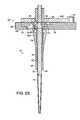
- FIGS. 1A and 1Bare side sectional views of a first embodiment of the invention shown in the released and latched positions respectively.
- FIG. 1Cis a top sectional view of the embodiment shown in FIGS. 1A and 1B .
- FIGS. 2A , 2 B and 2 Care side sectional views for an alternative embodiment of the invention shown in the released, latched and overforce positions respectively.
- FIG. 2Dis a sectional view taken along the line D-D in FIG. 2A .
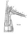
- FIGS. 3A and 3Bare a partial side sectional view and a top sectional view respectively for a third embodiment of the invention shown in the released position, and FIGS. 3C and 3D are the same views respectively of this embodiment in the latched position.
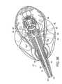
- FIG. 4is a side cut-away view of an alternative tip-identification embodiment of the invention.
- FIGS. 1A-1Ca first embodiment of the invention is shown wherein a tip 10 is mounted to a nozzle 12 which is part of a nozzle assembly 14 .
- Assembly 14includes a housing 16 having an outer sleeve 16 A and an inner sleeve 16 B.
- An ejector sleeve 18surrounds nozzle 12 , extending to a point near the distal end of the nozzle to which tip 10 is mounted, and fits at its proximal end between sleeves 16 A and 16 B of housing 16 .
- Nozzle 12is spring biased to the released position shown in FIG. 1A by a compression spring 20 extending between ring 22 fixed to nozzle 12 and the end of housing sleeve 16 B.
- Ejector sleeve 18is also spring biased to the released position of FIG. 1A by a compression spring 24 extending between an interior shoulder 26 of sleeve 18 and a shoulder 28 on inner housing sleeve 16 B.
- a flexible connectionfor example a flexible hose, should be provided connecting the nozzle to its drive piston or other drive mechanism for aspiration and dispensing.
- a latch mechanism 30which includes a button 32 mounted in outer sleeve 16 A of the housing.
- Button 32is biased toward the latched position shown in FIG. 1B by compression spring 34 mounted inside collar 36 extending from housing sleeve 16 A, spring 34 extending between an outside wall of housing sleeve 16 A and an inside wall of button 32 .
- Button 32has an enlarged, generally circular, inner end 38 and a narrower shaft portion 40 connecting the large end 38 to the remainder of the button 32 .
- Sleeve 18has a keyhole slot formed on the side thereof adjacent button 32 , the slot having an enlarged forward portion 42 which is slightly larger than enlarged tip 38 of button 32 , and a narrower rear portion 44 ( FIG. 1B ) which is slightly larger than shaft portion 40 of the latch button, but significantly smaller than enlarged portion 38 .
- the nozzle assembly 14is initially in the released position shown in FIG. 1A .
- the first thing that happensis that the bottom of tip 10 engages the distal or outer end 48 of ejector sleeve 18 , pushing sleeve 18 into housing 16 between housing sleeve 16 A and 16 B against the bias force of spring 24 .
- the tipeventually makes contact with the nozzle and becomes mounted thereto.
- nozzle 12moves rearward in housing 16 against the bias of spring 20 , preventing excessive force from being applied to mount tip 10 to nozzle 12 .
- the force with which the tip is mounted to the nozzleis thus carefully controlled so as to be enough to seal the nozzle/tip joint and to keep the tip in place, while still leaving the tip easily removable.
- sleeve 18is ultimately moved against the bias of spring 24 to a position where the enlarged portion 42 of the slot in sleeve 18 is adjacent large portion 38 of button 32 .
- button 32is moved outward under the bias force of spring 34 to move enlarged portion 38 into opening 42 in ejector sleeve 18 , thereby latching nozzle assembly 14 in the latched position shown in FIG. 1B .
- the click from latch 30 engagingprovides an audible feedback to the operator, and the movement of button 32 also provides a tactile and visual feedback to the operator, that the tip is fully mounted so that the operator may terminate the mounting operation. If the user continued to exert force after latching occurs, sleeve 48 ultimately bottoms against housing 16 , thus limiting travel of tip 10 and limiting the mounting force on the tip to that exerted by compressed spring 20 .
- nozzle 12is moved by its bias spring 20 to the position shown in FIG. 1B , this being the final position of the nozzle assembly with the tip mounted and the assembly in its latched position.
- springs 20 and 24such that spring 24 has significantly greater force than spring 20 , for example spring 24 being a three-pound spring and spring 20 a two-pound spring, the force with which the ejector sleeve strikes tip 10 when the ejector sleeve is unlatched will be sufficiently greater than the controlled force with which the tip is mounted to the nozzle to result in the tip being automatically ejected from nozzle 12 by ejector sleeve 18 as it moves to its released position.
- the energy stored in spring 24 when tip 10 is mounted to nozzle 12is utilized to automatically eject the tip when use of the tip has been completed.
- FIGS. 2A-2Dshow an alternative embodiment of the invention which has an alternative latch mechanism 30 ′ and also has an overforce feature not present in the embodiment of FIGS. 1A-1B .
- sleeve 18 ′rather than having a keyhole slot formed in its side, has a flange 60 with a shoulder 62 and an angled outer wall 64 formed at the bottom or inner end thereof.
- Latch 30 ′includes a slotted plate 66 which is biased to the latched position shown in FIG. 2B by tension spring 67 extending between posts fixed to housing portion 16 C and to plate 66 .
- Plate 66also has an extended groove 68 formed on the inner side thereof, which groove may for example extend for approximately 90° and which has an upper shoulder 70 .
- Plate 66slides on a housing member 16 C and is guided by four pins 72 extending from housing member 16 C, which pins fit in mating slots 74 in plate 66 (see FIG. 2D ).
- Plate 66has an insert 76 with an angled inner wall 78 .
- Plate 66also has an opening 80 in its top through which sleeve 18 ′ and nozzle 12 extend.
- latch assembly 30 ′is initially in the released position shown in FIG. 2A .
- tip 10when tip 10 is mounted over nozzle 12 , it initially makes contact with shoulder 48 of sleeve 18 ′ moving the sleeve into the nozzle assembly against the force of spring 24 .
- latch 30 ′When latch 30 ′ is to be released, the operator presses on surface 82 of plate 66 , moving the plate to its released position against the bias force applied thereto by spring 67 . This moves shoulder 70 of slot 60 away from flange 62 , permitting ejector sleeve 18 ′ to be moved to its released position by spring 24 . As for the prior embodiment, with spring 24 having a significantly greater force than spring 20 , this results in shoulder 48 of the ejector sleeve striking tip 10 with sufficient force to eject the tip from nozzle 12 .
- FIGS. 3A-3Dillustrate still another embodiment of the invention, which embodiment is utilized in conjunction with a pipette of the type described in application Ser. No. 09/873,522 of the applicant entitled HAND HELD PIPETTE which is being filed concurrently herewith.
- the pipette of this embodimentis substantially the same as the pipettes of the prior embodiments except for the latching mechanism 30 ′′.
- ejector sleeve 18 ′terminates in an angled flange 60 ( FIG. 3B ) having a shoulder 62 as for the embodiment of FIGS. 2A-2D .
- FIG. 3Bangled flange 60 having a shoulder 62 as for the embodiment of FIGS. 2A-2D .
- shoulder 62engages an internal end of a housing component 16 A′′ when the mechanism is in its released position to define the end position of the ejector sleeve.
- shoulder 62engages shoulders 90 of flanges 92 at the end of fingers 94 .
- button 32 ′′is depressed, fingers 94 are moved down to move flange 92 , and surface 90 thereof, out of contact with surface 62 of flange 60 , permitting ejector sleeve 18 ′ to return to the release position in a manner previously described to effect the ejection of tip 10 .
- FIGS. 3A-3Doperates in substantially the same way as the embodiments previously described.
- FIG. 4illustrates an embodiment of the invention which may be used, either alone or in combination with the prior embodiments, to permit the type of tip 10 being mounted to the pipette to be automatically detected.
- tips 10may have different dimensions, for example different length, volume, shape, orifice size, etc., may have different surface treatment, including no treatment or for example a low liquid retention treatment, may have a filter or no filter, may have different filters, or may have other different features.
- Tip differencescan require slight differences in pipette calibration, and use of the wrong tip can cause other problems. It is therefore desirable that the pipette be able to automatically detect the tip being mounted thereto both to facilitate proper calibration settings for the tip being used and to assure that the proper tip is being utilized.
- FIG. 4illustrates how the movable sleeve 18 and other mechanisms described above can be adapted to also perform tip type detection.
- nozzle 12is connected at a point remote from the tip, for example at the inner end of the nozzle, to a position detector 100 , which is shown in the figure as a linear encoder.
- a sensor 102is also provided to detect when sleeve 18 has moved by its full stroke. Where a latch 30 is provided, as for the previous embodiments, operation of the latch may be detected to indicate full stroke for the sleeve.
- sensor 102includes a flag 104 mounted to move with sleeve 18 and a sensor 106 , for example an optical sensor, which triggers when the flag reaches the sensor. While not shown in FIG. 4 to simplify the figure, this embodiment would also include springs 20 and 24 and related components, and may include a latch 30 when also used as a detipper.
- each different tip typeis designed to have slightly different base diameter, taper or other base dimension which does not affect its function, but which changes the point on the tip at which nozzle 12 makes contact with the tip 10 relative to the tip end making contact with shoulder 48 of sleeve 18 .
- Thismay also be achieved by providing an internal ring or shoulder 108 or some other feature on the inside of the tip base, the spacing of such shoulder from the base end of the tip or some other characteristic of the feature being controlled to indicate the tip type.
- Other detectable variations in the tip baseare also possible to provide an indication of tip type.
- the variations in the tip base indicated aboveresult in there being variations in the displacement of nozzle 12 for different tip types when detector 102 indicates that a full stroke has occurred for sleeve 18 .
- the reading from encoder 100 when sensor 102 generates an outputcan serve as an indication of tip type, a processor controlling the pipetting operation correlating the encoder reading with the appropriate tip type.
- encoder 100may be a simple switch which is closed for the displacement D for one tip type, but not the other.
- the release button strokecould be parallel to the axis of the nozzle, or at some other appropriate angle thereto.
- the release buttonshave been shown as being manually operable, automatic or semi-automatic release of the sleeve is also possible, for example in response to a pipetting operation being detected as completed, or for semi-automatic, in response to the operator closing a suitable contact.
- an extending sleeve or other suitable element of the rackmay co-act with shoulder 48 to retract ejector sleeve 18 to its latched position either instead of or in cooperation with tip 10 .
- This mechanismmay for example be employed in applications where the pipette has multiple nozzles to each of which tips are simultaneously mounted from a rack containing the tips. Other modifications in the detipping mechanism would be apparent to one skilled in the art.
- nozzles and tipshave been shown as having mating conical external and internal surfaces respectively, this is also not a limitation on the invention, nozzles and/or tips having other shapes capable of mating and sealing also being usable. Selected features could appear on the tips and/or nozzle to facilitate mating and sealing. It is also possible that when, for example, the end of the tip contacts the sleeve, it triggers the release of the nozzle to enter the tip with a controlled force, slightly displacing the tip end from the sleeve. For detipping, the nozzle could be retracted under spring or other suitable force to engage the end of the tip mounted to the end of the nozzle against the shoulder of the sleeve to effect detipping. Other mechanisms for achieving relative motion between the nozzle and sleeve are also possible.
- detipping mechanisms and tip detection mechanismscan be used together, each can also be used independently of the other.
- the detector or encoder 100 and sensor 102 used for tip detection and the location of such detector/sensormay vary with application, the specific such elements and locations discussed above being for purposes of illustration only.
- a sleeve mechanism other than full sleeve 18could be utilized as the ejector for detipping and/or for interacting with the tip and moving relative to the nozzle for tip identification.
Landscapes
- Chemical & Material Sciences (AREA)
- Health & Medical Sciences (AREA)
- General Health & Medical Sciences (AREA)
- Life Sciences & Earth Sciences (AREA)
- Analytical Chemistry (AREA)
- Biochemistry (AREA)
- Physics & Mathematics (AREA)
- General Physics & Mathematics (AREA)
- Immunology (AREA)
- Pathology (AREA)
- Clinical Laboratory Science (AREA)
- Chemical Kinetics & Catalysis (AREA)
- Automatic Analysis And Handling Materials Therefor (AREA)
- Devices For Use In Laboratory Experiments (AREA)
- Sampling And Sample Adjustment (AREA)
Abstract
Description
Claims (7)
Priority Applications (1)
| Application Number | Priority Date | Filing Date | Title |
|---|---|---|---|
| US11/243,940US8114362B2 (en) | 2000-06-26 | 2005-10-04 | Automatic pipette identification |
Applications Claiming Priority (4)
| Application Number | Priority Date | Filing Date | Title |
|---|---|---|---|
| US21420600P | 2000-06-26 | 2000-06-26 | |
| US09/873,842US6749812B2 (en) | 2000-06-26 | 2001-06-04 | Automatic pipette detipping |
| US10/612,252US6977062B2 (en) | 2000-06-26 | 2003-07-01 | Automatic pipette identification |
| US11/243,940US8114362B2 (en) | 2000-06-26 | 2005-10-04 | Automatic pipette identification |
Related Parent Applications (1)
| Application Number | Title | Priority Date | Filing Date |
|---|---|---|---|
| US10/612,252ContinuationUS6977062B2 (en) | 2000-06-26 | 2003-07-01 | Automatic pipette identification |
Publications (2)
| Publication Number | Publication Date |
|---|---|
| US20060104866A1 US20060104866A1 (en) | 2006-05-18 |
| US8114362B2true US8114362B2 (en) | 2012-02-14 |
Family
ID=22798204
Family Applications (3)
| Application Number | Title | Priority Date | Filing Date |
|---|---|---|---|
| US09/873,842Expired - LifetimeUS6749812B2 (en) | 2000-06-26 | 2001-06-04 | Automatic pipette detipping |
| US10/612,252Expired - Fee RelatedUS6977062B2 (en) | 2000-06-26 | 2003-07-01 | Automatic pipette identification |
| US11/243,940Expired - Fee RelatedUS8114362B2 (en) | 2000-06-26 | 2005-10-04 | Automatic pipette identification |
Family Applications Before (2)
| Application Number | Title | Priority Date | Filing Date |
|---|---|---|---|
| US09/873,842Expired - LifetimeUS6749812B2 (en) | 2000-06-26 | 2001-06-04 | Automatic pipette detipping |
| US10/612,252Expired - Fee RelatedUS6977062B2 (en) | 2000-06-26 | 2003-07-01 | Automatic pipette identification |
Country Status (5)
| Country | Link |
|---|---|
| US (3) | US6749812B2 (en) |
| EP (1) | EP1296762A2 (en) |
| JP (1) | JP2004501745A (en) |
| AU (1) | AU2001275195A1 (en) |
| WO (1) | WO2002000345A2 (en) |
Cited By (5)
| Publication number | Priority date | Publication date | Assignee | Title |
|---|---|---|---|---|
| US11369954B2 (en) | 2019-10-25 | 2022-06-28 | Mettler-Toledo Rainin, LLC | Powered positive displacement pipette assembly |
| US11389792B2 (en) | 2019-10-25 | 2022-07-19 | Mettler-Toledo Rainin, LLC | Syringe for powered positive displacement pipette |
| US11446672B2 (en) | 2019-10-25 | 2022-09-20 | Mettler-Toledo Rainin, LLC | Powered positive displacement pipette syringe piston grasping mechanism |
| US11471878B2 (en) | 2019-10-25 | 2022-10-18 | Mettler-Toledo Rainin, LLC | Powered positive displacement pipette |
| US11911767B2 (en) | 2019-10-25 | 2024-02-27 | Mettler-Toledo Rainin, LLC | Positive displacement pipette syringe identification system |
Families Citing this family (49)
| Publication number | Priority date | Publication date | Assignee | Title |
|---|---|---|---|---|
| DE19917375C2 (en)* | 1999-04-16 | 2001-09-27 | Hamilton Bonaduz Ag Bonaduz | Pipetting unit |
| DE69911474T2 (en)* | 1999-05-18 | 2004-07-22 | Socorex Isba S.A., | PIPETTE WITH DEVICE FOR EJECTING PIPETTE TIPS |
| FI108281B (en)* | 1999-07-07 | 2001-12-31 | Biohit Oyj | Suction device and method for use in a suction device |
| US6532837B1 (en)* | 2000-02-03 | 2003-03-18 | Rainin Instrument, Llc | Pipette device with tip ejector utilizing stored energy |
| US6749812B2 (en)* | 2000-06-26 | 2004-06-15 | Vistalab Technologies | Automatic pipette detipping |
| EP1296763B1 (en)* | 2000-06-26 | 2016-05-11 | Vistalab Technologies, Inc. | Handheld pipette |
| JP4271835B2 (en)* | 2000-08-18 | 2009-06-03 | アークレイ株式会社 | Pipette device |
| US7125520B2 (en)* | 2001-04-25 | 2006-10-24 | Oyster Bay Pump Works, Inc. | Reagent addition system and method |
| US7335337B1 (en)* | 2001-09-11 | 2008-02-26 | Smith James C | Ergonomic pipette tip and adapters |
| DE60237627D1 (en) | 2001-10-16 | 2010-10-21 | Matrix Technologies Corp | HAND-pipetting |
| US7284454B2 (en)* | 2004-05-27 | 2007-10-23 | Matrix Technologies Corporation | Hand held pipette |
| US20060027033A1 (en)* | 2002-10-16 | 2006-02-09 | Richard Cote | Hand-held pipette employing voice recognition control |
| FI120861B (en)* | 2002-11-08 | 2010-04-15 | Biohit Oyj | a multichannel pipette, |
| DE10330985A1 (en)* | 2003-07-09 | 2005-02-17 | Tecpharma Licensing Ag | Device for administering a fluid product with optical scanning |
| DE102004003433B4 (en)* | 2004-01-21 | 2006-03-23 | Eppendorf Ag | Pipetting device with a discharge device for pipette tips |
| US7641859B2 (en)* | 2004-02-11 | 2010-01-05 | Matrix Technologies Corporation | Pipette tip mounting and ejection assembly and associated pipette tip |
| CA2512353A1 (en)* | 2004-07-16 | 2006-01-16 | Stemcell Technologies Inc. | Automated pipette machine |
| ATE442201T1 (en)* | 2005-02-04 | 2009-09-15 | Hoffmann La Roche | PIPETTE FOR DISPOSABLE TIPS OF DIFFERENT SIZES |
| CA2634130C (en) | 2005-12-21 | 2021-08-03 | Meso Scale Technologies, Llc | Assay apparatuses, methods and reagents |
| EP1887330B1 (en)* | 2006-08-11 | 2009-11-18 | Biohit Oyj | Method for testing pipettes |
| US7662343B2 (en)* | 2006-10-24 | 2010-02-16 | Viaflo Corporation | Locking pipette tip and mounting shaft |
| US7662344B2 (en)* | 2006-10-24 | 2010-02-16 | Viaflo Corporation | Locking pipette tip and mounting shaft |
| US7794664B2 (en) | 2006-11-16 | 2010-09-14 | Idexx Laboratories, Inc. | Pipette tip |
| GB0717462D0 (en)* | 2007-09-07 | 2007-10-17 | Mole Genetics As | Liquid delivery apparatus |
| GB0717452D0 (en)* | 2007-09-07 | 2007-10-17 | Mole Genetics As | Separation apparatus |
| US20090071267A1 (en)* | 2007-09-17 | 2009-03-19 | Greg Mathus | Pipette tip ejection mechanism |
| USD620602S1 (en) | 2008-01-03 | 2010-07-27 | Vistalab Technologies, Inc. | Pipette |
| US20100058114A1 (en)* | 2008-08-29 | 2010-03-04 | Eads Na Defense Security And Systems Solutions, Inc. | Systems and methods for automated management of compliance of a target asset to predetermined requirements |
| US8277757B2 (en)* | 2009-09-29 | 2012-10-02 | Integra Biosciences Corp. | Pipette tip mounting shaft |
| US8236256B2 (en) | 2010-04-27 | 2012-08-07 | Thomas Friedlander | Apparatus and method for efficient and precise transfer of liquids |
| CN103282781B (en) | 2010-11-23 | 2015-10-14 | 安德鲁联合有限公司 | Apparatus and method for programmable manipulation of pipettes |
| WO2012162101A1 (en)* | 2011-05-20 | 2012-11-29 | Geneforge, Inc. | Drop-in nozzle |
| PL2633913T3 (en)* | 2012-03-01 | 2020-03-31 | Eppendorf Ag | Pipette device and multi-channel pipette device |
| MX2012010987A (en)* | 2012-09-24 | 2014-03-24 | Diana Elizabeth Calva Mendez | Pipette comprising a mobile nozzle. |
| EP3112026B1 (en)* | 2015-06-30 | 2018-03-14 | Sartorius Biohit Liquid Handling Oy | Pipette with a tip removal mechanism, a method for removing a tip, and a method for pipetting |
| CN106582907B (en)* | 2015-10-15 | 2021-05-18 | 常州福生生物技术有限公司 | Pipette capable of automatically withdrawing suction head |
| US11065614B2 (en) | 2016-06-15 | 2021-07-20 | Hamilton Company | Pipetting device, pipette tip coupler, and pipette tip: devices and methods |
| US11235318B2 (en) | 2016-06-15 | 2022-02-01 | Hamilton Company | Pipetting device, pipette tip coupler, and pipette tip: devices and methods |
| US10898892B2 (en) | 2016-06-15 | 2021-01-26 | Hamilton Company | Pipetting device, pipette tip coupler, and pipette tip: devices and methods |
| CN110465343B (en) | 2016-06-15 | 2022-06-14 | 汉密尔顿公司 | Pipetting devices, pipette tip couplers and pipette tips: devices and methods |
| WO2018015419A1 (en)* | 2016-07-22 | 2018-01-25 | Tecan Trading Ag | Pipette tip for an automated pipetting device and production method thereof |
| CH712735A1 (en)* | 2016-07-22 | 2018-01-31 | Tecan Trading Ag | Pipetting device with a liquid volume sensor and liquid processing system. |
| CH712764A2 (en)* | 2016-07-22 | 2018-01-31 | Tecan Trading Ag | Pipette tip comprising a volume measuring electrode and method for their preparation and pipetting device. |
| EP3560596A1 (en)* | 2018-04-23 | 2019-10-30 | Eppendorf AG | Pipette for use with a pipette tip and pipette family comprising multiple pipettes with different nominal volumes |
| EP3831486A1 (en) | 2019-12-06 | 2021-06-09 | Eppendorf AG | Pipette tip family comprising pipette tips for use with pipettes of a pipette family and pipette family comprising pipettes for use with pipette tips of a pipette tip family |
| EP3851191A1 (en)* | 2020-01-17 | 2021-07-21 | Eppendorf AG | Plunger lift pipette, data processing apparatus and system and method for operating a plunger-lift pipette |
| DE102020104422A1 (en) | 2020-02-19 | 2021-08-19 | Hamilton Bonaduz Ag | Method for assigning a pipette tip to a pipette tip class based on its pneumatic behavior |
| JP7576267B2 (en)* | 2021-02-05 | 2024-10-31 | 大成建設株式会社 | Remotely operated pipette device and structure for mounting pipette to robot arm |
| DE202021101129U1 (en) | 2021-03-05 | 2022-06-08 | Brand Gmbh + Co Kg | pipetting device |
Citations (103)
| Publication number | Priority date | Publication date | Assignee | Title |
|---|---|---|---|---|
| US586781A (en) | 1897-07-20 | Housek | ||
| US1923279A (en) | 1931-08-01 | 1933-08-22 | Sameshima Naotaro | Laundry sprayer |
| US2066977A (en) | 1935-04-27 | 1937-01-05 | Lawrence E Iler | Liquid dispenser |
| US2086348A (en) | 1936-09-26 | 1937-07-06 | Bernhardt Rudolph | Spraying apparatus |
| US2091404A (en) | 1936-12-02 | 1937-08-31 | Fred L Hicks | Pipette |
| US2710658A (en) | 1950-07-24 | 1955-06-14 | Charles K Huthsing | Fire extinguisher |
| US2796204A (en) | 1956-05-10 | 1957-06-18 | Math Moe | Dispenser cap for containers |
| US2876846A (en) | 1955-11-29 | 1959-03-10 | Gen Pacific Corp | Fire extinguisher head assembly |
| US3039500A (en) | 1959-01-22 | 1962-06-19 | Goldberg Moshe Levy | Pipette filling and liquid dispensing device |
| US3129854A (en) | 1961-08-21 | 1964-04-21 | Drackett Co | Dispensing device |
| US3134506A (en) | 1960-11-07 | 1964-05-26 | David G Way | Holder and puncturing device for cans |
| US3244009A (en) | 1963-08-22 | 1966-04-05 | Becton Dickinson Co | Automatic pipette |
| US3246559A (en) | 1961-12-26 | 1966-04-19 | Beckman Instruments Inc | Force feed cuvette |
| US3251420A (en) | 1964-04-20 | 1966-05-17 | Fire Guard Corp | Fire extinguisher with bottom mounted cartridge |
| US3558014A (en) | 1968-10-15 | 1971-01-26 | Bio Logics Inc | Automatic proportioner |
| US3719087A (en) | 1966-04-08 | 1973-03-06 | R Thiers | Pipetting apparatus and method |
| US3732735A (en) | 1971-06-17 | 1973-05-15 | Medical Laboratory Automation | Pipettes |
| US3754687A (en) | 1971-09-21 | 1973-08-28 | Kontes Glass Co | A multi-positional pipetting dispenser |
| US3757585A (en)* | 1968-08-16 | 1973-09-11 | Heller Labor | Pipette apparatus |
| US3786683A (en) | 1972-09-12 | 1974-01-22 | Alphamedics Mfg Corp | Hand-operated pipette |
| US3853012A (en) | 1971-10-04 | 1974-12-10 | Medical Laboratory Automation | Pipettes |
| US3933048A (en) | 1974-02-12 | 1976-01-20 | Medical Laboratory Automation, Inc. | Pipettes |
| US3954014A (en) | 1974-12-16 | 1976-05-04 | Becton, Dickinson And Company | Multiple shot pipetter |
| US3983375A (en)* | 1974-05-22 | 1976-09-28 | The United States Of America As Represented By The Secretary Of The Army | Tiltester |
| US3991617A (en) | 1974-10-15 | 1976-11-16 | Marteau D Autry Eric J H | Device for ejecting the removable tip of a pipette |
| US4151750A (en) | 1977-02-17 | 1979-05-01 | Kommandiittiyhtio Finnpipette Osmo A. Suovaniemi | Device for detaching and removing a disposable tip of a pipette |
| US4164870A (en) | 1978-04-10 | 1979-08-21 | Medical Laboratory Automation, Inc. | Pipettes |
| US4257268A (en) | 1979-08-24 | 1981-03-24 | Data Packaging Corporation | Pipetter |
| US4257267A (en) | 1978-10-18 | 1981-03-24 | Bohr Scientific Corporation | Dispenser unit with lockable actuating lever |
| US4263257A (en) | 1978-09-08 | 1981-04-21 | Metsaele Seppo Juhani | Pipette |
| US4283950A (en)* | 1978-08-04 | 1981-08-18 | Kommandiittiyhtio Finnpipette Osmo A. Suovaniemi | Device for detaching and removing a disposable tip of a pipette |
| US4298575A (en)* | 1978-09-04 | 1981-11-03 | Lkb Clinicon Aktiebolag | Pipetting and dosing device |
| US4369665A (en) | 1978-01-11 | 1983-01-25 | Indicon Inc. | Manually holdable automatic pipette |
| US4475666A (en) | 1981-08-31 | 1984-10-09 | American Hospital Supply Corporation | Automated liquid dispenser control |
| US4478094A (en)* | 1983-01-21 | 1984-10-23 | Cetus Corporation | Liquid sample handling system |
| US4528161A (en) | 1981-08-31 | 1985-07-09 | American Hospital Supply Corp. | Probe for automated liquid dispenser |
| US4567780A (en)* | 1984-03-12 | 1986-02-04 | American Hospital Supply Corporation | Hand-held pipette with disposable capillary |
| US4598840A (en) | 1983-10-11 | 1986-07-08 | Burg Donald E | Snap-in cartridge diluter |
| GB2172218A (en) | 1985-02-15 | 1986-09-17 | Rocket Of London Ltd | Pipetter tips for pipetters |
| US4671123A (en) | 1984-02-16 | 1987-06-09 | Rainin Instrument Co., Inc. | Methods and apparatus for pipetting and/or titrating liquids using a hand held self-contained automated pipette |
| US4679446A (en)* | 1985-09-09 | 1987-07-14 | Baxter Travenol Laboratories, Inc. | Multi-volume displacement pipette |
| US4690005A (en) | 1984-11-02 | 1987-09-01 | Labstystems Oy | Diluting dosage device |
| US4790176A (en) | 1986-11-27 | 1988-12-13 | Marteau D Autry Eric | Process and device for calibrating a sampling and metering pipette |
| US4815541A (en) | 1987-06-29 | 1989-03-28 | Arrington Richard C | Fire extinguisher |
| US4821586A (en) | 1988-02-25 | 1989-04-18 | Medical Laboratory Automation, Inc. | Programmable pipette |
| US4873059A (en)* | 1985-12-20 | 1989-10-10 | Fuji Photo Film Co., Ltd. | Pipette device |
| US4967604A (en) | 1985-12-17 | 1990-11-06 | Hamilton Bonaduz | Pipette and pipetting apparatus |
| US4988481A (en) | 1989-01-30 | 1991-01-29 | Labsystems Oy | Electrical pipette |
| EP0421785A2 (en) | 1989-10-04 | 1991-04-10 | Drummond Scientific Company | Pipetter device |
| EP0437906A1 (en) | 1990-01-17 | 1991-07-24 | Minoru Atake | System for measuring liquid |
| US5104624A (en) | 1989-10-20 | 1992-04-14 | Costar Corporation | Pipetter |
| US5214968A (en) | 1992-01-06 | 1993-06-01 | Drummond Scientific Company | Pipet filling and discharge device |
| US5320810A (en)* | 1992-05-13 | 1994-06-14 | Integrated Instrument Services, Inc. | Pipette with an axially stationary volume adjusting wheel |
| US5389341A (en) | 1992-06-24 | 1995-02-14 | Labsystems Oy | Knob pipette |
| US5394789A (en) | 1993-07-08 | 1995-03-07 | Evans; John P. | Manually operable device for metering air through a valve system for drawing into, retaining and evacuating material from a chamber |
| US5403553A (en) | 1992-04-13 | 1995-04-04 | Labsystems Oy | Jet part pipette |
| US5432085A (en)* | 1992-11-10 | 1995-07-11 | Warren; Richard J. | Cell feeder/harvester assembly |
| US5505097A (en) | 1991-02-05 | 1996-04-09 | Suovaniemi; Osmo | Pipette |
| US5509318A (en) | 1993-10-13 | 1996-04-23 | Manostat Corporation | Memory Mopet |
| US5585068A (en)* | 1990-02-20 | 1996-12-17 | Biochemical Diagnostics, Inc. | Apparatus for automatically separating a compound from a plurality of discrete liquid specimens |
| US5611784A (en) | 1993-06-30 | 1997-03-18 | Hamilton Company | Manual dispensing aid for a syringe |
| US5614153A (en) | 1995-05-26 | 1997-03-25 | Rainin Instrument Co., Inc. | Pipette tip ejector |
| US5616871A (en) | 1995-09-28 | 1997-04-01 | Drummond Scientific Company | Pipet gun assembly |
| US5620661A (en) | 1993-12-10 | 1997-04-15 | Eppendorf-Netherler-Hinz Gmbh | Pipette system |
| US5687884A (en) | 1994-03-21 | 1997-11-18 | Labcatal (Societe Anonyme) | Metering device for dispensing constant unit doses |
| US5747709A (en) | 1996-03-07 | 1998-05-05 | Nichiryo Co., Ltd. | Repetitive pipette |
| US5770159A (en) | 1994-08-16 | 1998-06-23 | Marteau D'autry; Eric | Pipette for dispensing successive volumes of liquid |
| US5792424A (en) | 1996-03-05 | 1998-08-11 | Rainin Instrument Co., Inc. | Manual pipette with delayed-action home position latch |
| US5807524A (en) | 1996-08-06 | 1998-09-15 | Rainin Instrument Co., Inc. | Pipette tip with pipette surface contamination protector |
| US5924603A (en) | 1995-03-10 | 1999-07-20 | Taplast Spa | Pump made of plastic for dispensing products from containers |
| US5970806A (en) | 1996-11-13 | 1999-10-26 | Labsystems Oy | Multi-cylinder pipette |
| US6090348A (en) | 1997-03-14 | 2000-07-18 | Becton, Dickinson And Company | Method for programming an electronic pipetter |
| US6105819A (en) | 1998-06-19 | 2000-08-22 | Allure Home Creation Co., Inc. | Container with a structural improvement |
| US6132582A (en)* | 1998-09-14 | 2000-10-17 | The Perkin-Elmer Corporation | Sample handling system for a multi-channel capillary electrophoresis device |
| US6197259B1 (en) | 1998-11-06 | 2001-03-06 | Rainin Instrument Co., Inc. | Easy eject pipette tip |
| US6240791B1 (en) | 1998-08-07 | 2001-06-05 | James W. Kenney | User-replaceable pipette gun grip |
| WO2001057490A1 (en) | 2000-02-03 | 2001-08-09 | Rainin Instrument Llc. | Pipette device with tip ejector utilizing stored energy |
| US20010019701A1 (en) | 1999-04-01 | 2001-09-06 | Ralf Braun | Method and device for detecting the type of replaceable piston-cylinder units for pipetting or dosing apparatus |
| US6299841B1 (en) | 1999-03-05 | 2001-10-09 | Rainin Instrument Co., Inc. | Bilaterally symmetrical battery powered microprocessor controlled lightweight hand-holdable electronic pipette |
| US20010036425A1 (en)* | 1995-10-12 | 2001-11-01 | Michel Gazeau | Device for transferring samples of micro-amounts of liquids |
| US20010035429A1 (en) | 2000-04-19 | 2001-11-01 | Colquhoun Mary Ellen | Liquid soap dispensing container |
| US6324925B1 (en) | 1998-06-10 | 2001-12-04 | Biohit Oyj | Suction device with means for removing a replaceable tip |
| US20020001545A1 (en) | 2000-06-26 | 2002-01-03 | Cronenberg Richard A. | Automatic pipette identification and detipping |
| US20020020233A1 (en) | 2000-08-03 | 2002-02-21 | Nobuyuki Baba | Hybrid pipette |
| US6365110B1 (en) | 2000-03-09 | 2002-04-02 | Rainin Instrument | Blowout springless manual air displacement pipette with mechanical assist for aiding in locating and maintaining pipette plunger at a home position |
| US6368872B1 (en)* | 1999-10-22 | 2002-04-09 | Tecan Trading Ag | Apparatus and method for chemical processing |
| US6428750B1 (en) | 2000-02-17 | 2002-08-06 | Rainin Instrument, Llc | Volume adjustable manual pipette with quick set volume adjustment |
| US6524531B1 (en) | 1999-09-14 | 2003-02-25 | Pharmacopeia, Inc. | Hand-held dispenser/aspirator |
| US6540964B2 (en) | 1999-12-24 | 2003-04-01 | Brand Gmbh + Co Kg | Pipette for a pipette system |
| US20030074988A1 (en) | 2001-07-06 | 2003-04-24 | Osmo Suovaniemi | Pipette device |
| US20030082078A1 (en) | 2001-10-30 | 2003-05-01 | Rainin Instrument, Llc | Pipette with improved pipette tip and mounting shaft |
| US20030099578A1 (en) | 2001-10-16 | 2003-05-29 | Richard Cote | Hand-held pipettor |
| US6627446B1 (en)* | 1998-07-02 | 2003-09-30 | Amersham Biosciences (Sv) Corp | Robotic microchannel bioanalytical instrument |
| US6737023B1 (en) | 1998-11-06 | 2004-05-18 | Rainin Instrument, Llc | Pipette with improved pipette tip mounting shaft |
| US6787111B2 (en)* | 1998-07-02 | 2004-09-07 | Amersham Biosciences (Sv) Corp. | Apparatus and method for filling and cleaning channels and inlet ports in microchips used for biological analysis |
| US20040208795A1 (en) | 2003-04-16 | 2004-10-21 | Hiroatsu Toi | Automatic liquid handling system |
| US6861034B1 (en) | 2000-11-22 | 2005-03-01 | Xerox Corporation | Priming mechanisms for drop ejection devices |
| US6874699B2 (en)* | 2002-10-15 | 2005-04-05 | Wisconsin Alumni Research Foundation | Methods and apparata for precisely dispensing microvolumes of fluids |
| US6878554B1 (en)* | 2000-03-20 | 2005-04-12 | Perkinelmer Las, Inc. | Method and apparatus for automatic pin detection in microarray spotting instruments |
| US20060051246A1 (en)* | 2004-09-07 | 2006-03-09 | Hiroatsu Toi | Automatic dispenser |
| US20060233669A1 (en)* | 1999-04-16 | 2006-10-19 | Armin Panzer | Pipette tip, pipette device, and combination of pipette tip and pipette device |
| US7276336B1 (en)* | 1999-07-22 | 2007-10-02 | Agilent Technologies, Inc. | Methods of fabricating an addressable array of biopolymer probes |
| US7870797B2 (en)* | 2006-04-03 | 2011-01-18 | Artel, Inc. | Apparatus and method for aspirating and dispensing liquid |
Family Cites Families (1)
| Publication number | Priority date | Publication date | Assignee | Title |
|---|---|---|---|---|
| US2876204A (en)* | 1951-12-07 | 1959-03-03 | Exxon Research Engineering Co | Wax-polyethylene-polyisobutylene |
- 2001
- 2001-06-04USUS09/873,842patent/US6749812B2/ennot_activeExpired - Lifetime
- 2001-06-04WOPCT/US2001/018026patent/WO2002000345A2/enactiveApplication Filing
- 2001-06-04JPJP2002505118Apatent/JP2004501745A/enactivePending
- 2001-06-04AUAU2001275195Apatent/AU2001275195A1/ennot_activeAbandoned
- 2001-06-04EPEP01941878Apatent/EP1296762A2/ennot_activeWithdrawn
- 2003
- 2003-07-01USUS10/612,252patent/US6977062B2/ennot_activeExpired - Fee Related
- 2005
- 2005-10-04USUS11/243,940patent/US8114362B2/ennot_activeExpired - Fee Related
Patent Citations (109)
| Publication number | Priority date | Publication date | Assignee | Title |
|---|---|---|---|---|
| US586781A (en) | 1897-07-20 | Housek | ||
| US1923279A (en) | 1931-08-01 | 1933-08-22 | Sameshima Naotaro | Laundry sprayer |
| US2066977A (en) | 1935-04-27 | 1937-01-05 | Lawrence E Iler | Liquid dispenser |
| US2086348A (en) | 1936-09-26 | 1937-07-06 | Bernhardt Rudolph | Spraying apparatus |
| US2091404A (en) | 1936-12-02 | 1937-08-31 | Fred L Hicks | Pipette |
| US2710658A (en) | 1950-07-24 | 1955-06-14 | Charles K Huthsing | Fire extinguisher |
| US2876846A (en) | 1955-11-29 | 1959-03-10 | Gen Pacific Corp | Fire extinguisher head assembly |
| US2796204A (en) | 1956-05-10 | 1957-06-18 | Math Moe | Dispenser cap for containers |
| US3039500A (en) | 1959-01-22 | 1962-06-19 | Goldberg Moshe Levy | Pipette filling and liquid dispensing device |
| US3134506A (en) | 1960-11-07 | 1964-05-26 | David G Way | Holder and puncturing device for cans |
| US3129854A (en) | 1961-08-21 | 1964-04-21 | Drackett Co | Dispensing device |
| US3246559A (en) | 1961-12-26 | 1966-04-19 | Beckman Instruments Inc | Force feed cuvette |
| US3244009A (en) | 1963-08-22 | 1966-04-05 | Becton Dickinson Co | Automatic pipette |
| US3251420A (en) | 1964-04-20 | 1966-05-17 | Fire Guard Corp | Fire extinguisher with bottom mounted cartridge |
| US3719087A (en) | 1966-04-08 | 1973-03-06 | R Thiers | Pipetting apparatus and method |
| US3757585A (en)* | 1968-08-16 | 1973-09-11 | Heller Labor | Pipette apparatus |
| US3558014A (en) | 1968-10-15 | 1971-01-26 | Bio Logics Inc | Automatic proportioner |
| US3732735A (en) | 1971-06-17 | 1973-05-15 | Medical Laboratory Automation | Pipettes |
| US3754687A (en) | 1971-09-21 | 1973-08-28 | Kontes Glass Co | A multi-positional pipetting dispenser |
| US3853012A (en) | 1971-10-04 | 1974-12-10 | Medical Laboratory Automation | Pipettes |
| US3786683A (en) | 1972-09-12 | 1974-01-22 | Alphamedics Mfg Corp | Hand-operated pipette |
| US3933048A (en) | 1974-02-12 | 1976-01-20 | Medical Laboratory Automation, Inc. | Pipettes |
| US3983375A (en)* | 1974-05-22 | 1976-09-28 | The United States Of America As Represented By The Secretary Of The Army | Tiltester |
| US3991617A (en) | 1974-10-15 | 1976-11-16 | Marteau D Autry Eric J H | Device for ejecting the removable tip of a pipette |
| USRE32210E (en) | 1974-10-15 | 1986-07-22 | Device for ejecting the removable tip of a pipette | |
| US3954014A (en) | 1974-12-16 | 1976-05-04 | Becton, Dickinson And Company | Multiple shot pipetter |
| US4151750A (en) | 1977-02-17 | 1979-05-01 | Kommandiittiyhtio Finnpipette Osmo A. Suovaniemi | Device for detaching and removing a disposable tip of a pipette |
| US4369665A (en) | 1978-01-11 | 1983-01-25 | Indicon Inc. | Manually holdable automatic pipette |
| US4164870A (en) | 1978-04-10 | 1979-08-21 | Medical Laboratory Automation, Inc. | Pipettes |
| US4283950A (en)* | 1978-08-04 | 1981-08-18 | Kommandiittiyhtio Finnpipette Osmo A. Suovaniemi | Device for detaching and removing a disposable tip of a pipette |
| US4298575A (en)* | 1978-09-04 | 1981-11-03 | Lkb Clinicon Aktiebolag | Pipetting and dosing device |
| US4263257A (en) | 1978-09-08 | 1981-04-21 | Metsaele Seppo Juhani | Pipette |
| US4257267A (en) | 1978-10-18 | 1981-03-24 | Bohr Scientific Corporation | Dispenser unit with lockable actuating lever |
| US4257268A (en) | 1979-08-24 | 1981-03-24 | Data Packaging Corporation | Pipetter |
| US4475666A (en) | 1981-08-31 | 1984-10-09 | American Hospital Supply Corporation | Automated liquid dispenser control |
| US4528161A (en) | 1981-08-31 | 1985-07-09 | American Hospital Supply Corp. | Probe for automated liquid dispenser |
| US4478094A (en)* | 1983-01-21 | 1984-10-23 | Cetus Corporation | Liquid sample handling system |
| US4478094B1 (en)* | 1983-01-21 | 1988-04-19 | ||
| US4598840A (en) | 1983-10-11 | 1986-07-08 | Burg Donald E | Snap-in cartridge diluter |
| US4671123A (en) | 1984-02-16 | 1987-06-09 | Rainin Instrument Co., Inc. | Methods and apparatus for pipetting and/or titrating liquids using a hand held self-contained automated pipette |
| US4567780A (en)* | 1984-03-12 | 1986-02-04 | American Hospital Supply Corporation | Hand-held pipette with disposable capillary |
| US4690005A (en) | 1984-11-02 | 1987-09-01 | Labstystems Oy | Diluting dosage device |
| GB2172218A (en) | 1985-02-15 | 1986-09-17 | Rocket Of London Ltd | Pipetter tips for pipetters |
| US4679446A (en)* | 1985-09-09 | 1987-07-14 | Baxter Travenol Laboratories, Inc. | Multi-volume displacement pipette |
| US4967604A (en) | 1985-12-17 | 1990-11-06 | Hamilton Bonaduz | Pipette and pipetting apparatus |
| US4873059A (en)* | 1985-12-20 | 1989-10-10 | Fuji Photo Film Co., Ltd. | Pipette device |
| US4790176A (en) | 1986-11-27 | 1988-12-13 | Marteau D Autry Eric | Process and device for calibrating a sampling and metering pipette |
| US4815541A (en) | 1987-06-29 | 1989-03-28 | Arrington Richard C | Fire extinguisher |
| US4821586A (en) | 1988-02-25 | 1989-04-18 | Medical Laboratory Automation, Inc. | Programmable pipette |
| US4988481A (en) | 1989-01-30 | 1991-01-29 | Labsystems Oy | Electrical pipette |
| EP0421785A2 (en) | 1989-10-04 | 1991-04-10 | Drummond Scientific Company | Pipetter device |
| US5104625A (en) | 1989-10-04 | 1992-04-14 | Drummond Scientific Company | Pipetter device |
| US5104624A (en) | 1989-10-20 | 1992-04-14 | Costar Corporation | Pipetter |
| EP0437906A1 (en) | 1990-01-17 | 1991-07-24 | Minoru Atake | System for measuring liquid |
| US5585068A (en)* | 1990-02-20 | 1996-12-17 | Biochemical Diagnostics, Inc. | Apparatus for automatically separating a compound from a plurality of discrete liquid specimens |
| US5505097A (en) | 1991-02-05 | 1996-04-09 | Suovaniemi; Osmo | Pipette |
| US5214968A (en) | 1992-01-06 | 1993-06-01 | Drummond Scientific Company | Pipet filling and discharge device |
| US5403553A (en) | 1992-04-13 | 1995-04-04 | Labsystems Oy | Jet part pipette |
| US5320810A (en)* | 1992-05-13 | 1994-06-14 | Integrated Instrument Services, Inc. | Pipette with an axially stationary volume adjusting wheel |
| US5389341A (en) | 1992-06-24 | 1995-02-14 | Labsystems Oy | Knob pipette |
| US5432085A (en)* | 1992-11-10 | 1995-07-11 | Warren; Richard J. | Cell feeder/harvester assembly |
| US5611784A (en) | 1993-06-30 | 1997-03-18 | Hamilton Company | Manual dispensing aid for a syringe |
| US5394789A (en) | 1993-07-08 | 1995-03-07 | Evans; John P. | Manually operable device for metering air through a valve system for drawing into, retaining and evacuating material from a chamber |
| US5509318A (en) | 1993-10-13 | 1996-04-23 | Manostat Corporation | Memory Mopet |
| US5620661A (en) | 1993-12-10 | 1997-04-15 | Eppendorf-Netherler-Hinz Gmbh | Pipette system |
| US5687884A (en) | 1994-03-21 | 1997-11-18 | Labcatal (Societe Anonyme) | Metering device for dispensing constant unit doses |
| US5770159A (en) | 1994-08-16 | 1998-06-23 | Marteau D'autry; Eric | Pipette for dispensing successive volumes of liquid |
| US5924603A (en) | 1995-03-10 | 1999-07-20 | Taplast Spa | Pump made of plastic for dispensing products from containers |
| US5614153A (en) | 1995-05-26 | 1997-03-25 | Rainin Instrument Co., Inc. | Pipette tip ejector |
| US5616871A (en) | 1995-09-28 | 1997-04-01 | Drummond Scientific Company | Pipet gun assembly |
| US20010036425A1 (en)* | 1995-10-12 | 2001-11-01 | Michel Gazeau | Device for transferring samples of micro-amounts of liquids |
| US5792424A (en) | 1996-03-05 | 1998-08-11 | Rainin Instrument Co., Inc. | Manual pipette with delayed-action home position latch |
| US5747709A (en) | 1996-03-07 | 1998-05-05 | Nichiryo Co., Ltd. | Repetitive pipette |
| US5807524A (en) | 1996-08-06 | 1998-09-15 | Rainin Instrument Co., Inc. | Pipette tip with pipette surface contamination protector |
| US5970806A (en) | 1996-11-13 | 1999-10-26 | Labsystems Oy | Multi-cylinder pipette |
| US6090348A (en) | 1997-03-14 | 2000-07-18 | Becton, Dickinson And Company | Method for programming an electronic pipetter |
| US6324925B1 (en) | 1998-06-10 | 2001-12-04 | Biohit Oyj | Suction device with means for removing a replaceable tip |
| US6105819A (en) | 1998-06-19 | 2000-08-22 | Allure Home Creation Co., Inc. | Container with a structural improvement |
| US6627446B1 (en)* | 1998-07-02 | 2003-09-30 | Amersham Biosciences (Sv) Corp | Robotic microchannel bioanalytical instrument |
| US6787111B2 (en)* | 1998-07-02 | 2004-09-07 | Amersham Biosciences (Sv) Corp. | Apparatus and method for filling and cleaning channels and inlet ports in microchips used for biological analysis |
| US6240791B1 (en) | 1998-08-07 | 2001-06-05 | James W. Kenney | User-replaceable pipette gun grip |
| US6132582A (en)* | 1998-09-14 | 2000-10-17 | The Perkin-Elmer Corporation | Sample handling system for a multi-channel capillary electrophoresis device |
| US6197259B1 (en) | 1998-11-06 | 2001-03-06 | Rainin Instrument Co., Inc. | Easy eject pipette tip |
| US6737023B1 (en) | 1998-11-06 | 2004-05-18 | Rainin Instrument, Llc | Pipette with improved pipette tip mounting shaft |
| US6299841B1 (en) | 1999-03-05 | 2001-10-09 | Rainin Instrument Co., Inc. | Bilaterally symmetrical battery powered microprocessor controlled lightweight hand-holdable electronic pipette |
| US20010019701A1 (en) | 1999-04-01 | 2001-09-06 | Ralf Braun | Method and device for detecting the type of replaceable piston-cylinder units for pipetting or dosing apparatus |
| US20060233669A1 (en)* | 1999-04-16 | 2006-10-19 | Armin Panzer | Pipette tip, pipette device, and combination of pipette tip and pipette device |
| US7276336B1 (en)* | 1999-07-22 | 2007-10-02 | Agilent Technologies, Inc. | Methods of fabricating an addressable array of biopolymer probes |
| US6524531B1 (en) | 1999-09-14 | 2003-02-25 | Pharmacopeia, Inc. | Hand-held dispenser/aspirator |
| US6368872B1 (en)* | 1999-10-22 | 2002-04-09 | Tecan Trading Ag | Apparatus and method for chemical processing |
| US6540964B2 (en) | 1999-12-24 | 2003-04-01 | Brand Gmbh + Co Kg | Pipette for a pipette system |
| WO2001057490A1 (en) | 2000-02-03 | 2001-08-09 | Rainin Instrument Llc. | Pipette device with tip ejector utilizing stored energy |
| US20030074989A1 (en) | 2000-02-03 | 2003-04-24 | Rainin Instrument, Llc | Pipette device with tip ejector utilizing stored energy |
| US6532837B1 (en) | 2000-02-03 | 2003-03-18 | Rainin Instrument, Llc | Pipette device with tip ejector utilizing stored energy |
| US6428750B1 (en) | 2000-02-17 | 2002-08-06 | Rainin Instrument, Llc | Volume adjustable manual pipette with quick set volume adjustment |
| US6365110B1 (en) | 2000-03-09 | 2002-04-02 | Rainin Instrument | Blowout springless manual air displacement pipette with mechanical assist for aiding in locating and maintaining pipette plunger at a home position |
| US6878554B1 (en)* | 2000-03-20 | 2005-04-12 | Perkinelmer Las, Inc. | Method and apparatus for automatic pin detection in microarray spotting instruments |
| US20010035429A1 (en) | 2000-04-19 | 2001-11-01 | Colquhoun Mary Ellen | Liquid soap dispensing container |
| US20060104866A1 (en)* | 2000-06-26 | 2006-05-18 | Vistalab Technologies, Inc. | Automatic pipette identification and detipping |
| US20020001545A1 (en) | 2000-06-26 | 2002-01-03 | Cronenberg Richard A. | Automatic pipette identification and detipping |
| US20020020233A1 (en) | 2000-08-03 | 2002-02-21 | Nobuyuki Baba | Hybrid pipette |
| US6861034B1 (en) | 2000-11-22 | 2005-03-01 | Xerox Corporation | Priming mechanisms for drop ejection devices |
| US20030074988A1 (en) | 2001-07-06 | 2003-04-24 | Osmo Suovaniemi | Pipette device |
| US20030099578A1 (en) | 2001-10-16 | 2003-05-29 | Richard Cote | Hand-held pipettor |
| US20030082078A1 (en) | 2001-10-30 | 2003-05-01 | Rainin Instrument, Llc | Pipette with improved pipette tip and mounting shaft |
| US6874699B2 (en)* | 2002-10-15 | 2005-04-05 | Wisconsin Alumni Research Foundation | Methods and apparata for precisely dispensing microvolumes of fluids |
| US20040208795A1 (en) | 2003-04-16 | 2004-10-21 | Hiroatsu Toi | Automatic liquid handling system |
| US20060051246A1 (en)* | 2004-09-07 | 2006-03-09 | Hiroatsu Toi | Automatic dispenser |
| US7870797B2 (en)* | 2006-04-03 | 2011-01-18 | Artel, Inc. | Apparatus and method for aspirating and dispensing liquid |
Non-Patent Citations (3)
| Title |
|---|
| Eppendorf EDOS 5221, Instruction Manual, Eppendorf, Germany. |
| Handi-Pet Pipetting Gun, General Diagnostics, 1973. |
| The Automatic Pipette, American Diagnostica. |
Cited By (7)
| Publication number | Priority date | Publication date | Assignee | Title |
|---|---|---|---|---|
| US11369954B2 (en) | 2019-10-25 | 2022-06-28 | Mettler-Toledo Rainin, LLC | Powered positive displacement pipette assembly |
| US11389792B2 (en) | 2019-10-25 | 2022-07-19 | Mettler-Toledo Rainin, LLC | Syringe for powered positive displacement pipette |
| US11446672B2 (en) | 2019-10-25 | 2022-09-20 | Mettler-Toledo Rainin, LLC | Powered positive displacement pipette syringe piston grasping mechanism |
| US11471878B2 (en) | 2019-10-25 | 2022-10-18 | Mettler-Toledo Rainin, LLC | Powered positive displacement pipette |
| US11850582B2 (en) | 2019-10-25 | 2023-12-26 | Mettler-Toledo Rainin, LLC | Powered positive displacement dispensing methods |
| US11911767B2 (en) | 2019-10-25 | 2024-02-27 | Mettler-Toledo Rainin, LLC | Positive displacement pipette syringe identification system |
| US12246315B2 (en) | 2019-10-25 | 2025-03-11 | Mettler-Toledo Rainin, LLC | Powered positive displacement pipette assembly |
Also Published As
| Publication number | Publication date |
|---|---|
| US20060104866A1 (en) | 2006-05-18 |
| WO2002000345A2 (en) | 2002-01-03 |
| US20040094638A1 (en) | 2004-05-20 |
| AU2001275195A1 (en) | 2002-01-08 |
| US20020001545A1 (en) | 2002-01-03 |
| EP1296762A2 (en) | 2003-04-02 |
| WO2002000345A3 (en) | 2002-06-20 |
| US6977062B2 (en) | 2005-12-20 |
| JP2004501745A (en) | 2004-01-22 |
| US6749812B2 (en) | 2004-06-15 |
Similar Documents
| Publication | Publication Date | Title |
|---|---|---|
| US8114362B2 (en) | Automatic pipette identification | |
| KR102782228B1 (en) | Electric displacement pipette | |
| KR102850643B1 (en) | Syringe for electric positive displacement pipette | |
| EP0979145B1 (en) | Combination of a pipette device and pipette tip with pipette surface contamination protector and use | |
| US12246315B2 (en) | Powered positive displacement pipette assembly | |
| US20240189825A1 (en) | Positive displacement pipette syringe identification system | |
| US11007517B2 (en) | Sub-one microliter pipette | |
| US4050316A (en) | Pipette aspirator device | |
| KR102782313B1 (en) | Electric Displacement Pipette Syringe Piston Grabber Device | |
| KR102871925B1 (en) | Positive displacement pipette syringe identification system | |
| CN114786817B (en) | Electric external piston type distribution method | |
| US20240066518A1 (en) | Multi-Tiered Pipette Tip Holder and Ejection Mechanism for a Dynamic Broad Volumetric Range Pipette |
Legal Events
| Date | Code | Title | Description |
|---|---|---|---|
| STCF | Information on status: patent grant | Free format text:PATENTED CASE | |
| FEPP | Fee payment procedure | Free format text:PAYOR NUMBER ASSIGNED (ORIGINAL EVENT CODE: ASPN); ENTITY STATUS OF PATENT OWNER: SMALL ENTITY | |
| REMI | Maintenance fee reminder mailed | ||
| FPAY | Fee payment | Year of fee payment:4 | |
| SULP | Surcharge for late payment | ||
| FEPP | Fee payment procedure | Free format text:MAINTENANCE FEE REMINDER MAILED (ORIGINAL EVENT CODE: REM.); ENTITY STATUS OF PATENT OWNER: SMALL ENTITY | |
| LAPS | Lapse for failure to pay maintenance fees | Free format text:PATENT EXPIRED FOR FAILURE TO PAY MAINTENANCE FEES (ORIGINAL EVENT CODE: EXP.); ENTITY STATUS OF PATENT OWNER: SMALL ENTITY | |
| STCH | Information on status: patent discontinuation | Free format text:PATENT EXPIRED DUE TO NONPAYMENT OF MAINTENANCE FEES UNDER 37 CFR 1.362 | |
| FP | Lapsed due to failure to pay maintenance fee | Effective date:20200214 | |
| AS | Assignment | Owner name:VISTABLAB TECHNOLOGIES, LLC, DELAWARE Free format text:CHANGE OF NAME;ASSIGNOR:VISTABLAB TECHNOLOGIES, INC.;REEL/FRAME:061162/0670 Effective date:20220323 Owner name:VISTABLAB TECHNOLOGIES, INC., NEW YORK Free format text:ASSIGNMENT OF ASSIGNORS INTEREST;ASSIGNOR:CRONENBERG, RICHARD A.;REEL/FRAME:060791/0333 Effective date:20010530 | |
| AS | Assignment | Owner name:VISTALAB TECHNOLOGIES, LLC, DELAWARE Free format text:CORRECTIVE ASSIGNMENT TO CORRECT THE THE NAME OF THE ASSIGNEE PREVIOUSLY RECORDED ON REEL 61162 FRAME 670. ASSIGNOR(S) HEREBY CONFIRMS THE CHANGE OF NAME;ASSIGNOR:VISTALAB TECHNOLOGIES, INC.;REEL/FRAME:069631/0520 Effective date:20220323 | |
| AS | Assignment | Owner name:VISTALAB TECHNOLOGIES LLC, NEW YORK Free format text:CHANGE OF ADDRESS;ASSIGNOR:VISTALAB TECHNOLOGIES LLC;REEL/FRAME:071689/0121 Effective date:20250620 |