US8114181B2 - Reflux trap device - Google Patents
Reflux trap deviceDownload PDFInfo
- Publication number
- US8114181B2 US8114181B2US12/319,031US31903108AUS8114181B2US 8114181 B2US8114181 B2US 8114181B2US 31903108 AUS31903108 AUS 31903108AUS 8114181 B2US8114181 B2US 8114181B2
- Authority
- US
- United States
- Prior art keywords
- distal
- chamber
- trap
- diffuser
- gas
- Prior art date
- Legal status (The legal status is an assumption and is not a legal conclusion. Google has not performed a legal analysis and makes no representation as to the accuracy of the status listed.)
- Active, expires
Links
- 238000010992refluxMethods0.000titleclaimsabstractdescription39
- 239000012530fluidSubstances0.000claimsabstractdescription31
- 238000001356surgical procedureMethods0.000claimsabstractdescription8
- 239000007789gasSubstances0.000claimsdescription74
- 239000011261inert gasSubstances0.000claimsdescription14
- 239000000523sampleSubstances0.000claimsdescription9
- 239000004020conductorSubstances0.000claimsdescription2
- 210000002381plasmaAnatomy0.000description16
- 210000001519tissueAnatomy0.000description11
- XKRFYHLGVUSROY-UHFFFAOYSA-NArgonChemical compound[Ar]XKRFYHLGVUSROY-UHFFFAOYSA-N0.000description4
- 239000000446fuelSubstances0.000description4
- 238000000034methodMethods0.000description4
- 210000004369bloodAnatomy0.000description3
- 239000008280bloodSubstances0.000description3
- 210000001124body fluidAnatomy0.000description3
- 238000005345coagulationMethods0.000description3
- 230000015271coagulationEffects0.000description3
- 238000004891communicationMethods0.000description3
- 238000010276constructionMethods0.000description3
- 239000012535impuritySubstances0.000description3
- 239000007788liquidSubstances0.000description2
- 238000000926separation methodMethods0.000description2
- 229910052786argonInorganic materials0.000description1
- 230000005465channelingEffects0.000description1
- 238000011109contaminationMethods0.000description1
- 230000000694effectsEffects0.000description1
- 230000005484gravityEffects0.000description1
- 238000003780insertionMethods0.000description1
- 230000037431insertionEffects0.000description1
- 239000003915liquefied petroleum gasSubstances0.000description1
- 230000037361pathwayEffects0.000description1
Images


Classifications
- A—HUMAN NECESSITIES
- A61—MEDICAL OR VETERINARY SCIENCE; HYGIENE
- A61B—DIAGNOSIS; SURGERY; IDENTIFICATION
- A61B18/00—Surgical instruments, devices or methods for transferring non-mechanical forms of energy to or from the body
- A61B18/04—Surgical instruments, devices or methods for transferring non-mechanical forms of energy to or from the body by heating
- A61B18/042—Surgical instruments, devices or methods for transferring non-mechanical forms of energy to or from the body by heating using additional gas becoming plasma
Definitions
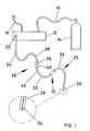
- the surgical probe 20comprises an electrode 28 disposed within a distal gas feed conduit including a first distal gas feed conduit section 30 and a second distal gas feed conduit section 32 terminating in an ingiter tip 34 disposed at the distal portion 35 of the surgical probe 20 to receive radio frequency power from the electrosurgical generator 12 to generate plasma when the igniter tip 34 is in close proximity to grounded tissue of a patient.
- the connector 26comprises a first connector member 36 affixed to the distal portion 38 of the proximal gas feed conduit 24 and a second connector member 40 affixed to the proximal portion 42 of the first distal gas feed conduit section 30 .
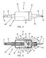
- the baffle 64further includes a substantially frustum conical diffuser member generally indicated as 82 including an inclined surface 84 terminating in a substantially flat or convex surface or trap 85 extending from the baffle element or base 76 into the proximal diffuser chamber 60 such that the inert gas G fed into the diffuser chamber 60 from the inert gas source 14 through a proximal gas inlet port 86 formed in the first shell member 50 of the trap housing impigns on the inclined surface 84 and the substantially flat or convex surface or tip 85 of the substantially frustum conical diffuser member 82 and directed or diffused through the gas flow apertures 80 into the distal deflection chamber 62 and through a distal gas outlet port 88 formed in the second shell member 52 of the trap housing to the surgical site on the patient (not shown) as shown in FIG.
- a substantially frustum conical diffuser membergenerally indicated as 82 including an inclined surface 84 terminating in a substantially flat or convex surface or trap 85 extending from the baffle element
Landscapes
- Health & Medical Sciences (AREA)
- Surgery (AREA)
- Engineering & Computer Science (AREA)
- Life Sciences & Earth Sciences (AREA)
- Biomedical Technology (AREA)
- Otolaryngology (AREA)
- Nuclear Medicine, Radiotherapy & Molecular Imaging (AREA)
- Plasma & Fusion (AREA)
- Physics & Mathematics (AREA)
- Heart & Thoracic Surgery (AREA)
- Medical Informatics (AREA)
- Molecular Biology (AREA)
- Animal Behavior & Ethology (AREA)
- General Health & Medical Sciences (AREA)
- Public Health (AREA)
- Veterinary Medicine (AREA)
- Surgical Instruments (AREA)
Abstract
Description
Claims (20)
Priority Applications (1)
| Application Number | Priority Date | Filing Date | Title |
|---|---|---|---|
| US12/319,031US8114181B2 (en) | 2008-12-31 | 2008-12-31 | Reflux trap device |
Applications Claiming Priority (1)
| Application Number | Priority Date | Filing Date | Title |
|---|---|---|---|
| US12/319,031US8114181B2 (en) | 2008-12-31 | 2008-12-31 | Reflux trap device |
Publications (2)
| Publication Number | Publication Date |
|---|---|
| US20100162893A1 US20100162893A1 (en) | 2010-07-01 |
| US8114181B2true US8114181B2 (en) | 2012-02-14 |
Family
ID=42283355
Family Applications (1)
| Application Number | Title | Priority Date | Filing Date |
|---|---|---|---|
| US12/319,031Active2030-04-28US8114181B2 (en) | 2008-12-31 | 2008-12-31 | Reflux trap device |
Country Status (1)
| Country | Link |
|---|---|
| US (1) | US8114181B2 (en) |
Cited By (11)
| Publication number | Priority date | Publication date | Assignee | Title |
|---|---|---|---|---|
| US20130221972A1 (en)* | 2012-02-28 | 2013-08-29 | Shimadzu Corporation | Discharge ionization current detector |
| US8608816B2 (en)* | 2012-01-10 | 2013-12-17 | Buffalo Filter Llc | Fluid filtration device and system |
| US9415160B2 (en) | 2012-05-21 | 2016-08-16 | Buffalo Filter Llc | Fluid filtration device and system |
| WO2017059228A1 (en) | 2015-10-02 | 2017-04-06 | Elucent Medical, Inc. | Signal tag detection components, devices, and systems |
| US9730764B2 (en) | 2015-10-02 | 2017-08-15 | Elucent Medical, Inc. | Signal tag detection components, devices, and systems |
| US10154799B2 (en) | 2016-08-12 | 2018-12-18 | Elucent Medical, Inc. | Surgical device guidance and monitoring devices, systems, and methods |
| US10278779B1 (en) | 2018-06-05 | 2019-05-07 | Elucent Medical, Inc. | Exciter assemblies |
| US11344382B2 (en) | 2014-01-24 | 2022-05-31 | Elucent Medical, Inc. | Systems and methods comprising localization agents |
| EP4302720A2 (en) | 2015-10-02 | 2024-01-10 | Elucent Medical, Inc. | Signal tag detection systems |
| US12210920B2 (en) | 2020-09-16 | 2025-01-28 | Elucent Medical, Inc. | Systems and methods comprising linked localization agents |
| US12364506B2 (en) | 2012-12-12 | 2025-07-22 | Buffalo Filter Llc | Filtration device and system |
Families Citing this family (1)
| Publication number | Priority date | Publication date | Assignee | Title |
|---|---|---|---|---|
| CN112472328B (en)* | 2020-12-03 | 2021-12-31 | 杨燕 | Dental handpiece of clearance is taken in anti-return |
Citations (18)
| Publication number | Priority date | Publication date | Assignee | Title |
|---|---|---|---|---|
| US540539A (en)* | 1895-06-04 | Air-brake branch-pipe drain-cu p | ||
| US1171530A (en)* | 1915-03-17 | 1916-02-15 | William C Michaels | Spark-arrester. |
| US3403497A (en)* | 1966-03-11 | 1968-10-01 | Allied Chem | Process and apparatus for liquid/gas separation |
| US6080228A (en)* | 1996-09-05 | 2000-06-27 | Jgc Corporation | Gas transfer pipe arrangement |
| US6090175A (en)* | 1999-02-02 | 2000-07-18 | Richard; Kenneth L. | Air inlet for a dust collector |
| US6099523A (en)* | 1995-06-27 | 2000-08-08 | Jump Technologies Limited | Cold plasma coagulator |
| US20030150195A1 (en)* | 2002-02-08 | 2003-08-14 | Chang Jo Won | Personal air cleaning apparatus |
| US20040128962A1 (en)* | 2003-01-03 | 2004-07-08 | Jeanfreau Bryan S. | Burp gas filtering and deodorizing device |
| US20070137484A1 (en)* | 2005-12-21 | 2007-06-21 | Porous Media | Operating room body gas evacuation system |
| US7258712B2 (en)* | 1997-11-21 | 2007-08-21 | Jlj Medical Devices International, Llc | Smoke evacuation system |
| US20070225700A1 (en)* | 2004-06-11 | 2007-09-27 | Erbe Elektromedizin Gmbh | Apparatus for Argon-Plasma Coagulation |
| US20070245699A1 (en)* | 2006-04-25 | 2007-10-25 | Vance Products Inc., D/B/A/ Cook Urological Inc. | Apparatus and method for collection of particulate matter during percutaneous procedures |
| US7311707B2 (en)* | 2002-06-27 | 2007-12-25 | Erbe Elektromedizin Gmbh | Connecting device for an electrosurgical instrument |
| US7335199B2 (en)* | 2000-02-22 | 2008-02-26 | Rhytec Limited | Tissue resurfacing |
| US7431748B2 (en)* | 2005-04-15 | 2008-10-07 | Enerco Group, Inc. | Separation device |
| US20090000484A1 (en)* | 2003-09-22 | 2009-01-01 | Tekran Instruments Corporation | Conditioning system and method for use in the measurement of mercury in gaseous emissions |
| US7799104B2 (en)* | 2006-04-24 | 2010-09-21 | Guido Valentini | Dust collection container with bladed element for power tool with suction capacity |
| US7979957B2 (en)* | 2008-11-04 | 2011-07-19 | Meyer Gretchen A | Apparatus for collecting lightweight packing particulates |
- 2008
- 2008-12-31USUS12/319,031patent/US8114181B2/enactiveActive
Patent Citations (20)
| Publication number | Priority date | Publication date | Assignee | Title |
|---|---|---|---|---|
| US540539A (en)* | 1895-06-04 | Air-brake branch-pipe drain-cu p | ||
| US1171530A (en)* | 1915-03-17 | 1916-02-15 | William C Michaels | Spark-arrester. |
| US3403497A (en)* | 1966-03-11 | 1968-10-01 | Allied Chem | Process and apparatus for liquid/gas separation |
| US6099523A (en)* | 1995-06-27 | 2000-08-08 | Jump Technologies Limited | Cold plasma coagulator |
| US6080228A (en)* | 1996-09-05 | 2000-06-27 | Jgc Corporation | Gas transfer pipe arrangement |
| US7258712B2 (en)* | 1997-11-21 | 2007-08-21 | Jlj Medical Devices International, Llc | Smoke evacuation system |
| US7959698B2 (en)* | 1997-11-21 | 2011-06-14 | Coopersurgical, Inc. | Smoke evacuation system |
| US20110041468A1 (en)* | 1997-11-21 | 2011-02-24 | JLJ Medical Devices International LLC, a Minnesota corporation | Smoke Evacuation System |
| US6090175A (en)* | 1999-02-02 | 2000-07-18 | Richard; Kenneth L. | Air inlet for a dust collector |
| US7335199B2 (en)* | 2000-02-22 | 2008-02-26 | Rhytec Limited | Tissue resurfacing |
| US20030150195A1 (en)* | 2002-02-08 | 2003-08-14 | Chang Jo Won | Personal air cleaning apparatus |
| US7311707B2 (en)* | 2002-06-27 | 2007-12-25 | Erbe Elektromedizin Gmbh | Connecting device for an electrosurgical instrument |
| US20040128962A1 (en)* | 2003-01-03 | 2004-07-08 | Jeanfreau Bryan S. | Burp gas filtering and deodorizing device |
| US20090000484A1 (en)* | 2003-09-22 | 2009-01-01 | Tekran Instruments Corporation | Conditioning system and method for use in the measurement of mercury in gaseous emissions |
| US20070225700A1 (en)* | 2004-06-11 | 2007-09-27 | Erbe Elektromedizin Gmbh | Apparatus for Argon-Plasma Coagulation |
| US7431748B2 (en)* | 2005-04-15 | 2008-10-07 | Enerco Group, Inc. | Separation device |
| US20070137484A1 (en)* | 2005-12-21 | 2007-06-21 | Porous Media | Operating room body gas evacuation system |
| US7799104B2 (en)* | 2006-04-24 | 2010-09-21 | Guido Valentini | Dust collection container with bladed element for power tool with suction capacity |
| US20070245699A1 (en)* | 2006-04-25 | 2007-10-25 | Vance Products Inc., D/B/A/ Cook Urological Inc. | Apparatus and method for collection of particulate matter during percutaneous procedures |
| US7979957B2 (en)* | 2008-11-04 | 2011-07-19 | Meyer Gretchen A | Apparatus for collecting lightweight packing particulates |
Cited By (25)
| Publication number | Priority date | Publication date | Assignee | Title |
|---|---|---|---|---|
| US8608816B2 (en)* | 2012-01-10 | 2013-12-17 | Buffalo Filter Llc | Fluid filtration device and system |
| US20130221972A1 (en)* | 2012-02-28 | 2013-08-29 | Shimadzu Corporation | Discharge ionization current detector |
| US9134274B2 (en)* | 2012-02-28 | 2015-09-15 | Shimadzu Corporation | Discharge ionization current detector |
| US9415160B2 (en) | 2012-05-21 | 2016-08-16 | Buffalo Filter Llc | Fluid filtration device and system |
| US12364506B2 (en) | 2012-12-12 | 2025-07-22 | Buffalo Filter Llc | Filtration device and system |
| US11344382B2 (en) | 2014-01-24 | 2022-05-31 | Elucent Medical, Inc. | Systems and methods comprising localization agents |
| US11135034B2 (en) | 2015-10-02 | 2021-10-05 | Elucent Medical, Inc. | Signal tag detection components, devices, and systems |
| US9730764B2 (en) | 2015-10-02 | 2017-08-15 | Elucent Medical, Inc. | Signal tag detection components, devices, and systems |
| US10245119B2 (en) | 2015-10-02 | 2019-04-02 | Elucent Medical, Inc. | Signal tag detection components, devices, and systems |
| US10245118B2 (en) | 2015-10-02 | 2019-04-02 | Elucent Medical, Inc. | Signal tag detection components, devices, and systems |
| WO2017059228A1 (en) | 2015-10-02 | 2017-04-06 | Elucent Medical, Inc. | Signal tag detection components, devices, and systems |
| US10751145B2 (en) | 2015-10-02 | 2020-08-25 | Elucent Medical, Inc. | Signal tag detection components, devices, and systems |
| US9987097B2 (en) | 2015-10-02 | 2018-06-05 | Elucent Medical, Inc. | Signal tag detection components, devices, and systems |
| US12245902B2 (en) | 2015-10-02 | 2025-03-11 | Elucent Medical, Inc. | Signal tag detection components, devices, and systems |
| EP4302720A2 (en) | 2015-10-02 | 2024-01-10 | Elucent Medical, Inc. | Signal tag detection systems |
| US11786333B2 (en) | 2015-10-02 | 2023-10-17 | Elucent Medical, Inc. | Signal tag detection components, devices, and systems |
| US10154799B2 (en) | 2016-08-12 | 2018-12-18 | Elucent Medical, Inc. | Surgical device guidance and monitoring devices, systems, and methods |
| US11298044B2 (en) | 2016-08-12 | 2022-04-12 | Elucent Medical, Inc. | Surgical device guidance and monitoring devices, systems, and methods |
| US12357192B2 (en) | 2016-08-12 | 2025-07-15 | Elucent Medical, Inc. | Surgical device guidance and monitoring devices, systems, and methods |
| US11540885B2 (en) | 2018-06-05 | 2023-01-03 | Elucent Medical, Inc. | Orthogonally isolated exciter with field steering |
| US11666391B2 (en) | 2018-06-05 | 2023-06-06 | Elucent Medical, Inc. | Exciter assemblies |
| US12186029B2 (en) | 2018-06-05 | 2025-01-07 | Elucent Medical, Inc. | Exciter assemblies |
| US11185375B2 (en) | 2018-06-05 | 2021-11-30 | Elucent Medical, Inc. | Exciter assemblies |
| US10278779B1 (en) | 2018-06-05 | 2019-05-07 | Elucent Medical, Inc. | Exciter assemblies |
| US12210920B2 (en) | 2020-09-16 | 2025-01-28 | Elucent Medical, Inc. | Systems and methods comprising linked localization agents |
Also Published As
| Publication number | Publication date |
|---|---|
| US20100162893A1 (en) | 2010-07-01 |
Similar Documents
| Publication | Publication Date | Title |
|---|---|---|
| US8114181B2 (en) | Reflux trap device | |
| US7763018B2 (en) | Cool-tip thermocouple including two-piece hub | |
| US8267934B2 (en) | Electrosurgical tool | |
| EP3616638B1 (en) | Bi-polar surgical instrument | |
| JP4078297B2 (en) | Sonde device | |
| US5669907A (en) | Plasma enhanced bipolar electrosurgical system | |
| US20020103485A1 (en) | Electrosurgical pencil with a smoke evacuating blade | |
| US7195630B2 (en) | Converting cutting and coagulating electrosurgical device and method | |
| JP5622838B2 (en) | Endoscopic surgical instrument | |
| US6802842B2 (en) | Electrosurgical tonsilar and adenoid electrode | |
| US6406476B1 (en) | Bipolar, fluid assisted coagulator/ablator probe for arthroscopy | |
| US7621911B2 (en) | Disposable/removable tubing set for use with an electrosurgical instrument | |
| CN109310462B (en) | Monopolar electrosurgical instrument, electrosurgical system, and method of manufacturing an electrosurgical instrument | |
| US20160051313A1 (en) | Attachment for Electrosurgical System | |
| US11191565B2 (en) | Surgical access port and assembly | |
| CN107847268A (en) | Multi-Feature Electrosurgical Instruments | |
| US20160235462A1 (en) | System and Method for Plasma Sealing of Tissue | |
| US20090318918A1 (en) | Suction ablator | |
| JP2022067074A (en) | Electric surgical instrument, electric surgical device, and method for operating electric surgical device | |
| US20230310057A1 (en) | Surgical cautery electrode and handpiece with integral smoke evacuation lumen | |
| CN104161588B (en) | electrosurgical tool and system | |
| US12396781B2 (en) | Electrosurgical pencil integrating module and an electrosurgical device possessing module thereof | |
| CN117598778A (en) | Water and electricity sword |
Legal Events
| Date | Code | Title | Description |
|---|---|---|---|
| AS | Assignment | Owner name:BOVIE MEDICAL CORPORATION,FLORIDA Free format text:ASSIGNMENT OF ASSIGNORS INTEREST;ASSIGNOR:GOGOLIN, GARY GERARD;REEL/FRAME:022093/0867 Effective date:20081223 Owner name:BOVIE MEDICAL CORPORATION, FLORIDA Free format text:ASSIGNMENT OF ASSIGNORS INTEREST;ASSIGNOR:GOGOLIN, GARY GERARD;REEL/FRAME:022093/0867 Effective date:20081223 | |
| STCF | Information on status: patent grant | Free format text:PATENTED CASE | |
| FEPP | Fee payment procedure | Free format text:PAYOR NUMBER ASSIGNED (ORIGINAL EVENT CODE: ASPN); ENTITY STATUS OF PATENT OWNER: SMALL ENTITY | |
| FPAY | Fee payment | Year of fee payment:4 | |
| AS | Assignment | Owner name:APYX MEDICAL CORPORATION, FLORIDA Free format text:CHANGE OF NAME;ASSIGNOR:BOVIE MEDICAL CORPORATION;REEL/FRAME:049166/0484 Effective date:20190109 | |
| MAFP | Maintenance fee payment | Free format text:PAYMENT OF MAINTENANCE FEE, 8TH YR, SMALL ENTITY (ORIGINAL EVENT CODE: M2552); ENTITY STATUS OF PATENT OWNER: SMALL ENTITY Year of fee payment:8 | |
| AS | Assignment | Owner name:MIDCAP FUNDING IV TRUST, MARYLAND Free format text:SECURITY INTEREST;ASSIGNOR:APYX MEDICAL CORPORATION;REEL/FRAME:062913/0001 Effective date:20230217 | |
| MAFP | Maintenance fee payment | Free format text:PAYMENT OF MAINTENANCE FEE, 12TH YR, SMALL ENTITY (ORIGINAL EVENT CODE: M2553); ENTITY STATUS OF PATENT OWNER: SMALL ENTITY Year of fee payment:12 | |
| AS | Assignment | Owner name:PERCEPTIVE CREDIT HOLDINGS IV, LP, AS ADMINISTRATIVE AGENT, NEW YORK Free format text:SECURITY INTEREST;ASSIGNOR:APYX MEDICAL CORPORATION;REEL/FRAME:065523/0013 Effective date:20231108 | |
| AS | Assignment | Owner name:APYX MEDICAL CORPORATION, FLORIDA Free format text:RELEASE BY SECURED PARTY;ASSIGNOR:MIDCAP FUNDING IV TRUST;REEL/FRAME:065612/0105 Effective date:20231108 |