US8114163B2 - Method and apparatus for adjusting height and angle for a radial head - Google Patents
Method and apparatus for adjusting height and angle for a radial headDownload PDFInfo
- Publication number
- US8114163B2 US8114163B2US10/999,297US99929704AUS8114163B2US 8114163 B2US8114163 B2US 8114163B2US 99929704 AUS99929704 AUS 99929704AUS 8114163 B2US8114163 B2US 8114163B2
- Authority
- US
- United States
- Prior art keywords
- component
- head
- prosthesis system
- inner core
- stem
- Prior art date
- Legal status (The legal status is an assumption and is not a legal conclusion. Google has not performed a legal analysis and makes no representation as to the accuracy of the status listed.)
- Expired - Lifetime, expires
Links
Images


Classifications
- A—HUMAN NECESSITIES
- A61—MEDICAL OR VETERINARY SCIENCE; HYGIENE
- A61F—FILTERS IMPLANTABLE INTO BLOOD VESSELS; PROSTHESES; DEVICES PROVIDING PATENCY TO, OR PREVENTING COLLAPSING OF, TUBULAR STRUCTURES OF THE BODY, e.g. STENTS; ORTHOPAEDIC, NURSING OR CONTRACEPTIVE DEVICES; FOMENTATION; TREATMENT OR PROTECTION OF EYES OR EARS; BANDAGES, DRESSINGS OR ABSORBENT PADS; FIRST-AID KITS
- A61F2/00—Filters implantable into blood vessels; Prostheses, i.e. artificial substitutes or replacements for parts of the body; Appliances for connecting them with the body; Devices providing patency to, or preventing collapsing of, tubular structures of the body, e.g. stents
- A61F2/02—Prostheses implantable into the body
- A61F2/30—Joints
- A61F2/38—Joints for elbows or knees
- A61F2/3804—Joints for elbows or knees for elbows
- A—HUMAN NECESSITIES
- A61—MEDICAL OR VETERINARY SCIENCE; HYGIENE
- A61F—FILTERS IMPLANTABLE INTO BLOOD VESSELS; PROSTHESES; DEVICES PROVIDING PATENCY TO, OR PREVENTING COLLAPSING OF, TUBULAR STRUCTURES OF THE BODY, e.g. STENTS; ORTHOPAEDIC, NURSING OR CONTRACEPTIVE DEVICES; FOMENTATION; TREATMENT OR PROTECTION OF EYES OR EARS; BANDAGES, DRESSINGS OR ABSORBENT PADS; FIRST-AID KITS
- A61F2/00—Filters implantable into blood vessels; Prostheses, i.e. artificial substitutes or replacements for parts of the body; Appliances for connecting them with the body; Devices providing patency to, or preventing collapsing of, tubular structures of the body, e.g. stents
- A61F2/02—Prostheses implantable into the body
- A61F2/30—Joints
- A61F2/46—Special tools for implanting artificial joints
- A61F2/4637—Special tools for implanting artificial joints for connecting or disconnecting two parts of a prosthesis
- A—HUMAN NECESSITIES
- A61—MEDICAL OR VETERINARY SCIENCE; HYGIENE
- A61F—FILTERS IMPLANTABLE INTO BLOOD VESSELS; PROSTHESES; DEVICES PROVIDING PATENCY TO, OR PREVENTING COLLAPSING OF, TUBULAR STRUCTURES OF THE BODY, e.g. STENTS; ORTHOPAEDIC, NURSING OR CONTRACEPTIVE DEVICES; FOMENTATION; TREATMENT OR PROTECTION OF EYES OR EARS; BANDAGES, DRESSINGS OR ABSORBENT PADS; FIRST-AID KITS
- A61F2/00—Filters implantable into blood vessels; Prostheses, i.e. artificial substitutes or replacements for parts of the body; Appliances for connecting them with the body; Devices providing patency to, or preventing collapsing of, tubular structures of the body, e.g. stents
- A61F2/02—Prostheses implantable into the body
- A61F2/30—Joints
- A61F2002/30001—Additional features of subject-matter classified in A61F2/28, A61F2/30 and subgroups thereof
- A61F2002/30316—The prosthesis having different structural features at different locations within the same prosthesis; Connections between prosthetic parts; Special structural features of bone or joint prostheses not otherwise provided for
- A61F2002/30329—Connections or couplings between prosthetic parts, e.g. between modular parts; Connecting elements
- A61F2002/30383—Connections or couplings between prosthetic parts, e.g. between modular parts; Connecting elements made by laterally inserting a protrusion, e.g. a rib into a complementarily-shaped groove
- A61F2002/30387—Dovetail connection
- A—HUMAN NECESSITIES
- A61—MEDICAL OR VETERINARY SCIENCE; HYGIENE
- A61F—FILTERS IMPLANTABLE INTO BLOOD VESSELS; PROSTHESES; DEVICES PROVIDING PATENCY TO, OR PREVENTING COLLAPSING OF, TUBULAR STRUCTURES OF THE BODY, e.g. STENTS; ORTHOPAEDIC, NURSING OR CONTRACEPTIVE DEVICES; FOMENTATION; TREATMENT OR PROTECTION OF EYES OR EARS; BANDAGES, DRESSINGS OR ABSORBENT PADS; FIRST-AID KITS
- A61F2/00—Filters implantable into blood vessels; Prostheses, i.e. artificial substitutes or replacements for parts of the body; Appliances for connecting them with the body; Devices providing patency to, or preventing collapsing of, tubular structures of the body, e.g. stents
- A61F2/02—Prostheses implantable into the body
- A61F2/30—Joints
- A61F2002/30001—Additional features of subject-matter classified in A61F2/28, A61F2/30 and subgroups thereof
- A61F2002/30316—The prosthesis having different structural features at different locations within the same prosthesis; Connections between prosthetic parts; Special structural features of bone or joint prostheses not otherwise provided for
- A61F2002/30535—Special structural features of bone or joint prostheses not otherwise provided for
- A61F2002/30604—Special structural features of bone or joint prostheses not otherwise provided for modular
- A—HUMAN NECESSITIES
- A61—MEDICAL OR VETERINARY SCIENCE; HYGIENE
- A61F—FILTERS IMPLANTABLE INTO BLOOD VESSELS; PROSTHESES; DEVICES PROVIDING PATENCY TO, OR PREVENTING COLLAPSING OF, TUBULAR STRUCTURES OF THE BODY, e.g. STENTS; ORTHOPAEDIC, NURSING OR CONTRACEPTIVE DEVICES; FOMENTATION; TREATMENT OR PROTECTION OF EYES OR EARS; BANDAGES, DRESSINGS OR ABSORBENT PADS; FIRST-AID KITS
- A61F2/00—Filters implantable into blood vessels; Prostheses, i.e. artificial substitutes or replacements for parts of the body; Appliances for connecting them with the body; Devices providing patency to, or preventing collapsing of, tubular structures of the body, e.g. stents
- A61F2/02—Prostheses implantable into the body
- A61F2/30—Joints
- A61F2/38—Joints for elbows or knees
- A61F2/3804—Joints for elbows or knees for elbows
- A61F2002/3827—Radial components
- A—HUMAN NECESSITIES
- A61—MEDICAL OR VETERINARY SCIENCE; HYGIENE
- A61F—FILTERS IMPLANTABLE INTO BLOOD VESSELS; PROSTHESES; DEVICES PROVIDING PATENCY TO, OR PREVENTING COLLAPSING OF, TUBULAR STRUCTURES OF THE BODY, e.g. STENTS; ORTHOPAEDIC, NURSING OR CONTRACEPTIVE DEVICES; FOMENTATION; TREATMENT OR PROTECTION OF EYES OR EARS; BANDAGES, DRESSINGS OR ABSORBENT PADS; FIRST-AID KITS
- A61F2220/00—Fixations or connections for prostheses classified in groups A61F2/00 - A61F2/26 or A61F2/82 or A61F9/00 or A61F11/00 or subgroups thereof
- A61F2220/0025—Connections or couplings between prosthetic parts, e.g. between modular parts; Connecting elements
Definitions
- the present inventionrelates to a radial implant and more specifically relates to a method and apparatus for adjusting the height and/or the angle of the radial implant.
- the proximal aspect of the radius, or radial headis frequently injured either in isolation or in combination with injury to other bony or ligamentous structures of the elbow joint.
- the radial headmay also be fractured in association with injuries to the forearm axis, including disruptions of the interosseous membrane between the radius and the ulna. Whether in isolation or in combination with other injuries, fractures of the radial head can be difficult to treat.
- Fractures of the radial headare either reconstructable or unreconstructable.
- a certain percentage of fracturesare not amenable to reconstruction due to the degree comminution or severity of the fracture.
- unreconstructable radial head fracturesresult from high energy trauma and are therefore frequently associated with significant injuries to other osseous or ligamentous structures of the elbow joint or forearm.
- restoration of the stabilizing function of the radial headis critical to allow the ligaments of the elbow or forearm to heal in appropriate relationships, thereby restoring stability to the elbow or forearm. This stabilizing function depends, in part, upon re-establishing the appropriate distance between the capitellum and the proximal shaft of the radius.
- Prosthetic replacement of the radial headhas evolved rather slowly.
- the first widely used prosthetic radial headwas introduced in the 1970's and was composed of silicone. Silicone implants placed in various joints throughout the body led to “silicone synovitis,” in which the silicone induced an inflammatory response within the joint. Further, silicone radial head prostheses were found to be incapable of resisting the stresses to which the radial head is subjected, rendering it less useful in stabilizing the injured elbow or forearm.
- a modular prosthesis system for replacement of a head portion of a radiusincludes a head component having a first connection portion that connects to a second connection portion and a collar component having the second connection portion and a third connection portion.
- the systemalso includes a stem component including a fourth connection portion that connects with the third connection portion, the stem component having a stem anchoring portion that connects to the radius.
- FIG. 1is a front view of a stem component
- FIG. 2is a side view of the stem component from a perspective perpendicular to that of FIG. 1 ;
- FIG. 3is a top view of the stem component
- FIG. 4is a front view of an inner core of a head component
- FIG. 5is a side view of the inner core of the head component from a perspective perpendicular to that of FIG. 4 ;
- FIG. 6is a top view of the inner core of the head component
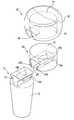
- FIG. 7is a front view of an outer shell of the head component
- FIG. 8is a side view of an outer shell of a head component from a perspective perpendicular to that of FIG. 7 ;
- FIG. 9is an exploded perspective view of an assembly of a stem component, a inner core, and an outer shell;
- FIG. 10is a perspective view of an assembled prostheses
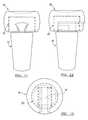
- FIG. 11is a front view of an assembled prostheses
- FIG. 12is a side view of an assembled prostheses from a perspective perpendicular to that of FIG. 11 ;
- FIG. 13is a top view of an assembled prostheses
- FIG. 14is a posterior oblique view of a human elbow depicting a radial head prostheses in position within a proximal radius bone and articulating with a capitellum of a distal humerus;
- FIGS. 15 and 16are perspective views of a tool that can be used to insert or remove a head component from a stem component via a translational force;
- FIG. 17is a perspective view of the head component showing the outer shell body completely enveloping the inner core
- FIG. 18is similar to FIG. 17 but shows the head component disassembled
- FIG. 19Ais a perspective view of the head component showing the inner core extending beneath the outer shell body
- FIG. 19Bis similar to FIG. 19A but shows a mechanical fastener securing the outer shell body to the inner core;
- FIG. 19Cis similar to FIG. 19A but shows the head components as a single piece
- FIG. 20is similar to FIG. 19 but shows the head component disassembled
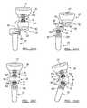
- FIG. 21Ais a perspective view of the head component, the stem component and a collar component
- FIG. 21Bis similar to FIG. 21A but shows an alternative configuration between the head component, the stem component and the collar component;
- FIG. 22is similar to FIG. 21A but the components are assembled
- FIG. 23are perspective views of exemplary alternative connections between components of the modular prosthesis.
- FIG. 24is similar to FIG. 21A but shows an angled collar component
- FIG. 25is similar to FIG. 24 but the components are assembled
- FIGS. 26A-26Dare perspective views of exemplary alternative connections between the head component, the stem component and the collar component.
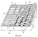
- FIG. 27is perspective view of a kit including a plurality of head components, stem components and collar components having various sizes, shapes and configurations.
- Ring headis defined as the essentially cylindrical protrusion found at the proximal end of a radius bone.
- radial headcan also be used to modify or describe the prostheses of the present invention.
- Longitudinal axisis an imaginary line that is defined by the center of the stem component in the direction of intramedullary canal insertion.
- the “longitudinal axis”is also roughly defined as running parallel to a centerline running between the proximal and distal end of the radius bone.
- Transverse axisor “assembly axis” is an axis that intersects the longitudinal axis.
- the transverse axiscan be linear or non-linear.
- the axiscan be arcuate, provided the assembly axis intersects the longitudinal axis.
- angles >0° and ⁇ 180°qualify as “transverse.”
- the transverse axiscan be from 45° to 135° with respect to the longitudinal axis in order to significantly benefit from the modular assembly benefits described herein. In many instances, an essentially perpendicular transverse axis with respect to the longitudinal axis will be present.
- Protuberancecan include any protuberance functional with the present invention, particularly with respect to certain locking mechanisms.
- protuberancescan be convexities.
- Concavityis intended to describe an open space defined by a mounting portion of a stem component, or an inner core. With respect to a locking mechanism, the concavity can be configured to inversely match and accept a protuberance, though this is not required.
- “Intramedullary”shall mean the within the marrow cavity of a bone.
- “Native”is used to describe the condition of the bone or the head of a bone prior to damage or removal.
- a radial head prosthesisthat enables the assembly without having to significantly remove or manipulate bone and tissue as part of an overhead assembly.
- a sliding mechanism for the assembly of the modular radial head prostheses as described hereinimprovement over the commercially available prosthetics can be achieved.
- a sliding mechanism in conjunction with a locking mechanismenables the secure attachment and reasonable removal of a head component from an intact stem component, without the disadvantages associated with head component insertion along the longitudinal axis.
- a stem component 10is shown in FIG. 1 .
- the stem component 10comprises an anchoring portion 12 and a mounting portion 14 .
- the anchoring portion 12is the portion that is anchored within a canal of the proximal radius, providing support to the radial head prosthetic as a whole.
- the anchoring portion 12is tapered and can be coated or textured to allow bone ingrowth after insertion into the radius bone of a patient.
- the anchoring portioncan be cemented, press fit, and/or impacted into the intramedullary canal as is known by those skilled in the art. If a cement is used, then a cement such as, for example, methyl methacrylate, can be used.
- the mounting portion 14is configured as a dovetail shaped mount when viewed from the front perspective shown in FIG. 1 .
- the stem protuberances 16 a , 16 bare formed of a rigid material such as metal, alloy, or ceramic. If the rigid material is metal or alloy, appropriate materials can include, for example, titanium, stainless steel, and cobalt chrome.
- FIG. 2a side view of the stem component 10 shown.
- the stem protuberances 16 aare configured to span a distance of approximately one half of the depth of the mounting portion.
- the stem protuberance 16 b(not shown) is configured similarly.
- FIG. 3a top view of the stem component 10 is shown.
- the stem protuberances 16 a , 16 bare not visible from this perspective, and thus, are shown as dashed lines.
- the stem component shown in FIGS. 1-3has the dual purpose of attaching the prostheses to the radius bone, as well as to provide a mechanism to mount a head component (not shown) to the stem component.
- the head componentcan be a single unit, in the embodiment shown in the subsequent figures, the head component comprises an outer shell and an inner core.
- the practical reason for thisis that it is often desirable to have a rigid outer shell, while having a less rigid inner core when utilizing the locking mechanism described in FIGS. 1-13 .
- the inner corecan be a rigid material as well.
- FIGS. 3-6show an embodiment of the inner core
- FIGS. 7-8show an embodiment of the outer shell.
- the inner core and the outer shellwill generally be pre-assembled prior to surgery.
- An inner core 20 of a head componentis shown.
- An inner core body 22defines the shape of the inner core 20 and can be constructed of a polymeric resin, such as, for example, a high molecular weight polyethylene. Additionally, the outer dimension of the inner core body 22 can be cylindrical in shape. Attached to the inner core body are a pair of inner core protuberances 24 a , 24 b .
- the inner core body 22 and the inner core protuberances 24 a , 24 bdefine an inner core open channel or groove 26 that can be slidably connected to the mounting portion (not shown) of the stem component (not shown).
- the inner core protuberances 24 a , 24 bcan be constructed of the same material as the inner core body 22 , though this is not required.
- the inner core body 22 and the inner core protuberances 24 a , 24 bcan be a single polymeric or copolymeric unit.
- the inner core protuberances 24 a , 24 bare constructed of a compressible material so that the inner core protuberances 24 a , 24 b can pass by the stem protuberances (not shown) as part of a locking mechanism.
- the inner core protuberances 24 a , 24 bare configured such that they span only a portion of the depth of the open channel 26 .
- the inner core protuberances 24 a , 24 bare positioned opposite the stem protuberances (not shown) such that when the head component is in place on the stem component, all of the protuberances act together to form a locking mechanism.
- the inner core open channel 26does not traverse completely through the inner core body 22 .
- the inner core groove 26is just long enough such that when the mounting portion of the stem component (not shown) is tracked within the inner core open channel 26 , the mounting portion and the inner core 20 will be coaxial.
- a radial head component 30is shown.
- An outer shell body 32is fashioned to approximate the dimensions of a damaged or removed radial head. Thus, the outer dimension is roughly cylindrical, having a slightly concaved top portion 37 for natural articulation with the capitellum (not shown). Because outer shell body 32 is the portion of the prostheses that will articulate with the capitellum upon joint movement, this structure can be constructed of a biologically acceptable rigid material. Such a material can include, for example, metal, alloy, or ceramic. If the rigid material is metal or alloy, appropriate materials can include, for example, titanium, stainless steel, and cobalt chrome.
- the outer shell body 32also defines an inner hollow 34 that accepts the inner core (not shown) when the head component is fully constructed.
- an outer shell open channel or groove 36is present that essentially matches the inner core open channel or groove (not shown) such that the mounting portion (not shown) can be inserted into the aligned grooves.
- the outer shell body 32 and the inner core (not shown)can both be cylindrical components that define dovetail shaped grooves, which substantially fits the dovetail shaped mount of the stem component. If the inner core 20 and the outer shell body 32 are two different materials (as in the present embodiment), then the two components can be fitted together with a bonding cement, friction fit, and/or other known techniques.
- the outer shell open channel or groove 36can be present at only one edge of the outer shell body 32 and its edges can be tapered to avoid damage to the articular cartilage of the proximal radio-ulnar joint.
- the outer shell body 32should be composed of metal suitable for biologic implantation, and be shaped to approximate the dimensions of the radial head. If the surgeon requires assistance in selecting an appropriately sized head component, then an estimate of the patient's anatomy can be ascertained using plastic trials (not shown) provided for this purpose. Though not required, the edges of the outer shell groove 36 can be tapered to avoid damage to the proximal radio-ulnar joint.
- the radial head component 30is shown having an outer shell body 32 , which defines an outer shell hollow 34 .
- the outer shell hollow 34fits over an outer dimension of the inner core body 22 of the inner core 20 .
- a pair of the stem protuberances 16 a , 16 bcan pass over a pair of the inner core protuberances 24 a , 24 b , as the inner core protuberances 24 a , 24 b are configured to compress.
- the stem protuberances 16 a , 16 bcompletely pass over the inner core protuberances 24 a , 24 b , the stem protuberances can lock into a pair of inner core concavities 25 a , 25 b , respectively.
- the inner core concavities 25 a , 25 bare configured in dimension to inversely match the stem protuberances 16 a , 16 b such that a locking action occurs.
- an abutment of the protuberancesoccurs and can prevent unwanted motion between the head component and the stem component after the prostheses is inserted.
- the protuberancesalso serve to prevent the head component from slipping off the stem component without intentional force, e.g., during removal by a surgeon.
- the stem componentcan be placed in a canal of the radius bone, followed by the fitting of the head component.
- FIG. 10shows the stem component, the inner core 20 and the outer shell body 32 in a completed assembly configuration.
- the cylindrical inner core 20 componentfits centrally within the outer shell body 32 .
- the mounting portion 14 of the stem component 10is inserted fully within the core and shell, all three components will be configured coaxially.
- the outer shell body 32 and the inner core 20are shown as two separate components, in practice, the outer shell body 32 and the inner core 20 can be assembled and sterilized prior to attachment to the mounting portion 14 of the stem component 10 .
- the surgeonwould only be required to slide the assembled head component onto the stem component 10 by lining up the open channels 26 , 36 with the mounting portion 14 , and sliding the radial head component 30 into place.
- FIGS. 11-13additional views of an assembled prosthesis are shown.
- the protuberances 16 a , 16 b , 24 a , 24 bcan be slid past opposing protuberances under sufficient translational force.
- the protuberancesare shaped such that the force required to press the protuberances past their opposing protuberances is intentional and reasonable, but not excessive.
- FIG. 14is a posterior oblique view of the human elbow depicting the radial head prostheses in position within the proximal radius bone 38 and articulating with the capitellum 39 of the distal humerus.
- the anchoring portion 12is within the medullary canal of the proximal radius 38
- the radial head 30is articulating with the capitellum 39 of the distal humerus.
- FIGS. 15 and 16a tool 40 is shown that can be used with the prostheses of the present invention is shown.
- the tool 40is positioned in a first orientation with respect to proximal radius 38 for inserting the radial head component 30 onto the mounting portion 14 .
- the tool 40is positioned in a second orientation with respect to the proximal radius 38 for removing the radial head component 30 from the mounting portion.
- a first arm 42 and a second arm 44are shown that enable or surgeon to create translational force 45 to be placed on the radial head component 30 .
- the first arm 42 and the second arm 44are tracked parallel to one another by a track 46 and a slider 48 .
- the second arm 44is connected to a handle 52 by a hinge 50 .
- the handle 52is designed such that by applying a squeezing force 51 , translational force 45 is applied to the head component 30 .
- the translational force mechanismis a lever.
- At the end of the first arm 42is a pulling member 54 that acts to stabilize the proximal radius 38 (or alternatively, the mounting portion 14 ).
- At the end of the second arm 44is a pushing member 56 for pushing the radial head component 30 onto the mounting portion 14 .
- the same tool 40 as described in FIG. 15can be used by flipping it upside down.
- the first arm 42now acts to provide the translational force 45 and the second arm 44 stabilizes the proximal radius 38 (or alternatively, the mounting portion 14 ).
- the armsare characterized as the first arm 42 and the second arm 44 for convenience only. It would be apparent to one skilled in the art that the first arm or the second arm can function as the stabilizer. Likewise, the first arm or the second arm can act to provide desired translational force.
- the toolcan press the components onto one another while maintaining alignment of the dovetail shaped mount and groove.
- the rigidity provided by the polyethyleneis sufficient to secure the modular components to each other. Removal is accomplished by generating sufficient translational pressure on the head component with the use of a specially designed handle.
- This toolbinds the far end of the head component while stabilizing the proximal radius bone, and thereby the stem component. Translational force is generated which presses the protuberances of the inner core past the protuberances of the mounting portion, thereby releasing the head component from the stem component.
- a procedure that can be followed for the insertion of the modular radial head prosthesesis as follows. If necessary, after resection of a substantially unreconstructable radial head bone, a proximal edge of the radius bone can be removed by transverse sawing or some other removal technique. After the damaged radial head has been removed, the medullary canal of the bone can then be broached with one or more of a series of broaches, the shapes of which approximate the various stem sizes available. Once an appropriate size stem component size has been selected, the anchoring portion can be inserted into the proximal radius bone such that the mounting portion protrudes from the proximal radius bone. The head component can then selected based upon parameters such as proper ligament tensioning, circumference, and height.
- the forearmcan be rotated so that the mounting portion is positioned to receive the head portion, i.e., an assembled outer shell/inner core combination or a single piece head component.
- the head componentcomprises an outer shell and an inner core
- the head componentcan either be assembled at the time of manufacture or by the surgeon. In any event, the outer shell groove and the inner core groove should be position such that the grooves line up for accepting the mounting portion.
- a clickwill be palpable as the stem protuberances and the inner core protuberances slip fully past each other.
- the prostheseswill then be secure within the canal of the proximal radius bone and is positioned to articulate with the capitellum of the distal humerus.
- a modular prostheses system for replacement of the radial head portion of the radius bonecomprising a stem component and a head component.
- the stem componentcomprises an anchoring portion and a mounting portion
- the head componentcan have an open channel configured to connect to the mounting portion along an assembly axis that is transverse to a longitudinal axis of the stem component.
- the connectioncan be by a sliding motion.
- the transverse anglewill generally be from about 45° to 135° with respect to the longitudinal axis. This is due to the fact that as you approach angles closer to parallel with the longitudinal axis, the head component becomes more difficult to put in place. In many incidences, the assembly axis will intersect the longitudinal axis at essentially a perpendicular angle.
- the systemcan further comprise a locking mechanism to prevent the open channel of the head component from indeliberately sliding on the mounting portion once connected to the mounting portion. This is desirable because once the prosthesis has become part of the functioning elbow joint, any slippage could require surgery for repair. Thus, the only circumstance wherein sliding should be allowed should occur at the hand of the surgeon, with deliberate action.
- the locking mechanismcan be configures such as that shown in FIGS. 1-13 , or by any other locking mechanism known by those skilled in the mechanical arts. For example, after sliding the head component onto the mounting portion, the head component can be locked in place with a pin or screw.
- the mounting portioncan be configured for allowing the head component to slide along a single axis via the open channel.
- FIGS. 1-13Such an embodiment is shown in FIGS. 1-13 where the dovetail-shaped mounting portion is inversely matched with a dovetailed-shaped groove.
- head componentcan be slid onto the mounting portion along a single axis only.
- the head componentcan be inserted and removed from the mounting portion with a specially designed tool.
- the system of the present inventioncan further comprise a tool for inserting and removing the head component while the stem component is in place within a radial canal.
- a toolcan comprise a first arm for inserting the head component onto the mounting portion or removing the head component from the mounting portion; a second arm for stabilizing the radius bone; and a translational force mechanism for moving the first arm while the second arm stabilizes the radius bone.
- translationand “stabilizing” are used loosely depending on whether the tool is being used for insertion or removal of the head component, the arm acting to provide the translational force and the arm act to provide stabilization can be changed.
- the termsare relative as to the action, rather than to the specific structure.
- the first arm carrying out the translational insertiondoes so by a pushing force
- the second armstabilizes the radius bone by a pulling force.
- the first armremoves the head component by a pulling force (i.e., the tool is flipped over, and the second arm stabilizes the radius bone by a pushing force).
- a method for fitting a damaged radius bone with a modular radial head prosthesescomprising the steps of securing a stem component partially within a proximal intramedullary canal of the damaged radius bone such that a mounting portion of stem component is exposed above the damaged radius bone; selecting a head component that will provide a desired result; and sliding the head component onto the mounting portion in a direction along an assembly axis that is transverse to a longitudinal axis of the stem component.
- a preliminary step of removing a radial head of the damaged radius boneis carried out prior to fitting the radius bone with the prostheses of the present invention, though there can be circumstances where this preliminary step is not necessary.
- the stem componentmay be desirable to carry out the preliminary step of sizing the stem component to securely fit within the proximal canal. This can be done using a set of broaches designed for this purpose.
- the stem componentcan be secured within the intramedullary canal by one of a number of techniques including the use of cement, firm pressure into the canal, or impacting the stem component into the canal, for example.
- the next step of selecting an appropriate head componentis carried out. Considerations can include assessing a desired tensioning of one or more ligaments attached to the radius bone and/or assessing the height and shape of the head component to be used. Aid in this area can be provided by the use of trials designed for this purpose. Such trials can be plastic structures configured to approximate the size and shape of the head component to be ultimately placed on the mounting portion. It is appreciated that the trials can be made of other suitable materials.
- the inner core 20 and the outer shell body 32 of the radial head component 30are shown.
- the outer shell body 32can be comprised of ultra high molecular weight polyethylene.
- the outer shell body 32can also be comprised of a suitable metal material such as cobalt chrome, titanium, or other biocompatible material.
- the inner core 20can also be made of a material that is identical to the radial head component 30 ( FIG. 19B ) or as above described made of a softer material ( FIG. 19A ) that can otherwise be compressed when inserted over the stem protuberances 16 a , 16 b or any other biocompatible material, as above detailed and as shown in FIG. 1 .
- the inner core 20 and the outer shell body 32are comprised of the same material ( FIG. 19B ), for example, a metal such as cobalt chrome or titanium.
- a mechanical fastener 60can be used to secure the outer shell body 32 to the inner core 20 in lieu of the compressible inner core protuberances 24 a , 24 b ( FIG. 4 ).
- the head component 30can be made of single piece of biocompatible material ( FIG. 19C ), such that the head component is a unitary construction. It is appreciated that a plurality of the fasteners 60 can be used to secure the outer shell body 32 to the inner core 20 .
- other types of exemplary connectionsmay be used such as chemical bonding, shrink fit and taper junctions.
- outer shell body 32can be configured to snap fit onto the inner core 20 , while another method can include mechanical threading on the inner core 20 with complementary mechanical threading on the outer shell body 32 .
- the outer body shell 32 of the radial head component 30can also be configured to completely envelope the inner core 20 , as shown in FIGS. 17 and 18 , or otherwise be positioned over the inner core 20 as to not cover the open channel 26 thus exposing varying lengths of the inner core 20 , as shown in FIGS. 19A , 19 B and 20 .
- a collar component 62can be used to connect the radial head component 30 to the stem component 10 .
- the collar component 62can have a collar open channel 64 and a collar mounting location 66 , which are complementary to the head open channel 36 and the stem mounting location 14 , respectively.
- the collar component 62can be configured to vertically align the radial head component 30 and the stem component 10 , as shown in FIG. 22 .
- An angled collar component 68can also be configured to provide a pre-determined angle between the radial head component 30 and the stem component 10 , as shown in FIG. 25 .
- the angled collar component 68can be configured at various angles, for example, between vertical (i.e., 180°) and narrower angles to match the native geometry of the bones, as shown in FIG. 14 . It can be appreciated that the radial head component 30 and the stem component 10 can attach to the collar component 62 or the angled collar component 68 regardless of its length or angle.
- the radial head component 30can have a unitary construction (i.e., one-piece), thus omitting the inner core 20 and outer shell body 32 .
- the radial head component 30can be constructed of metal such as cobalt chrome, titanium or any other suitable biocompatible material for implementation into the human body.
- the radial head component 30can be secured to either the stem mounting portion 14 or the collar mounting portion 66 of the collar component 62 with a suitable mechanical fastener 60 .
- the head component 30includes a first connection portion 70 that connects to a second connection portion 72 on the collar component 62 .
- the collar component 62also includes a third connection portion 74 that connects to a fourth connection portion 76 on the stem component 10 .
- the second connection portion 72can be distal from the third connection portion 74 and can be on opposite ends of the collar component 62 .
- the first connection portion 70can be the open channel 26 on the head component 30 .
- the second connection portioncan be the collar mounting portion 66 .
- the third connection portion 76can be the collar open channel 64 .
- the fourth connection portion 78can be the mounting portion of 14 on the stem component 10 . As shown in FIG.
- the first connection portion 70can be a head component mounting portion 78 .
- the second connection portioncan be the collar open channel 64 .
- the third connection portion 74can be the collar mounting portion 66 .
- the fourth connection portion 76can be a stem component open channel 80 .
- the various components of the modular prosthesis systemcan use various connection portions with myriad configurations.
- the mounting portion on the various componentsis configured in a T-shaped protrusion generally indicated by reference numeral 82 .
- a complementary open channel 84is similarly configured in a T-shape to accept the T-shaped protrusion 82 .
- FIG. 23it can be appreciated that other configurations are suitable such as, but not limited to, a cylindrical configuration 86 , a dove-tail configuration 88 , and a star shaped configuration 90 .
- various fitscan be used such as, but not limited to, an interference fit, a taper lock fit and a sliding fit secured by a mechanical fastener 60 .
- the mechanical fastener 60can be inserted through an aperture and contact the T-shaped protrusion.
- the mechanical fastenercan also connect to the T-shaped protrusion such that the fastener 60 can be inserted through a fastener aperture 92 in the open channel and/or in the mounting location.
- the fastenercan be placed at various angles and position to further secure the components of the prosthesis.
- a collar length 94( FIG. 22 ) and a collar angle 96 ( FIG. 24 ) can be variable among multiple collar components 62 , 68 , while the collar mounting location 66 and the collar open channel 64 can have a fixed dimension to facilitate interchangeability among other stem components 10 and head components 30 .
- an inner core length 98can vary such that the inner core body 22 can be completely contained within the head component inner hollow 34 or extend beyond an outer body shell aperture 100 .
- various dimensionssuch as length, diameter, thickness etc. can be varied to more closely match the native bone structure of the patient, as shown in FIG. 14 .
- a threaded post 102 and a complementary threaded aperture 104can be used to connect the collar component 62 to the head component 30 and the stem component 10 .
- the first connection portion 70 of the head component 30can include the threaded aperture 104 .
- the second connection portion 72 of the collar component 62can include the threaded post 102 that can engage with and connect to the complimentary threaded aperture 104 on the head component 30 .
- the third connection portion 74 of the collar component 62can include the above described T-shaped protrusion 82 .
- the fourth connection portion 76 of the stem component 10can include the above described T-shaped channel 84 , which can connect with the T-shaped protrusion 82 included on the third connection portion 74 of the collar component 62 .
- the angled collar component 68FIG. 26D
- the collar component 62FIGS. 26A-26C
- the first connection portion 70 on the head component 30can include the T-shaped protrusion 82 .
- the second connection portion 72 of the collar component 62can include the complimentary T-shaped channel 84 that can connect with and engage the T-shaped protrusion 82 included on the first connection portion 70 of the head component 30 .
- the third connection portion 74 of the collar component 62can include the threaded post 102 .
- the fourth connection portion 76 of the stem component 10can include the complementary threaded aperture 104 that can engage to and connect with the threaded post 102 included on the third connection portion 74 of the collar component 62 .
- the first connection portion 70 of the head component 30can include the threaded aperture 104 .
- the second connection portion 72 of the collar component 62can include the threaded post 102 which can engage with and connect to the threaded aperture 104 included on the first connection portion of the head component 30 .
- the third connection portion 74 of the collar component 62can also include the threaded post 102 .
- the first connection portion 76 on the stem component 10can include the threaded aperture 104 that can engage with and connect to the threaded post 102 on the third connection portion 74 of the collar component 62 .
- the first connection portion 70 of the head component 30can include the threaded aperture 104 .
- the second connection portion 72 of the angle collar 68can include the threaded post 102 , which can engage with and connect to the threaded aperture 104 .
- the third connection portion of the angle collar 68can also include the threaded post 102 .
- the fourth connection portion 76 of the stem component 10can include the threaded aperture 104 , which can engage with and connect to the threaded post 102 .
- height 94 ( FIG. 26C ) and/or angle 96 of either the collar component 62 or angled collar component 68can be varied to accommodate the native bone structure, as shown in FIG. 14 .
- the height 106FIG.
- first connection portion 70 , the second connection portion 72 , the third connection portion 74 and the fourth connection portion 76can be configured in various ways including, but not limited to, the respective threaded posts 102 and threaded apertures 104 and various combinations thereof.
- a kit 108is shown including exemplary stem components 10 , collar components 62 , angled collar components 68 and head components 30 .
- the kit 108can include a collection of various sizes and shapes of the above-mentioned components.
- the kit 108can include a plurality of angled collar component 68 having varying collar angles 94 .
- the kit 108can include a plurality of head components 30 having varying shaped concave top portions 37 that complement the native bone to which they will contact.
- the kit 108can also include a plurality of stem components 10 such that each of the stem components 10 has varying size anchor portions 12 in thickness, taper design and/or length.
- the kit 108can include a plurality of collar components 62 having varying collar lengths 92 to further accommodate the native bone structure. It can be appreciated that the kit 108 can include numerous head components 30 , angled collar components 68 , collar components 62 , and stem components 10 of various sizes, shapes and configurations so that the modular prosthesis system can be assembled to closely match the native bone structure.
- the kit 108provides the plurality of head components 30 , angled collar components 68 , collar components 62 , and stem components 10 that can be assembled and adjusted during a medical procedure to provide a fit that can be in-situ determined and adjusted. It can be appreciated that a medical professional can determine a proper length and angle and select among the components of the kit 108 to achieve the proper length and angle. Nevertheless, the medical professional can select and substitute components in-situ to adjust to achieve the proper length and angle.
Landscapes
- Health & Medical Sciences (AREA)
- Orthopedic Medicine & Surgery (AREA)
- Transplantation (AREA)
- Heart & Thoracic Surgery (AREA)
- Oral & Maxillofacial Surgery (AREA)
- Cardiology (AREA)
- Engineering & Computer Science (AREA)
- Biomedical Technology (AREA)
- Physical Education & Sports Medicine (AREA)
- Vascular Medicine (AREA)
- Life Sciences & Earth Sciences (AREA)
- Animal Behavior & Ethology (AREA)
- General Health & Medical Sciences (AREA)
- Public Health (AREA)
- Veterinary Medicine (AREA)
- Prostheses (AREA)
Abstract
Description
Claims (39)
Priority Applications (11)
| Application Number | Priority Date | Filing Date | Title |
|---|---|---|---|
| US10/999,297US8114163B2 (en) | 2000-04-10 | 2004-11-29 | Method and apparatus for adjusting height and angle for a radial head |
| US12/578,052US8425615B2 (en) | 2000-04-10 | 2009-10-13 | Method and apparatus for adjusting height and angle for a radial head |
| US12/794,196US8920509B2 (en) | 2000-04-10 | 2010-06-04 | Modular radial head prosthesis |
| US12/827,568US8366781B2 (en) | 2000-04-10 | 2010-06-30 | Modular prosthesis and use thereof for replacing a radial head |
| US12/872,600US20100312349A1 (en) | 2000-04-10 | 2010-08-31 | Modular prosthesis and use thereof for replacing a radial head |
| US13/025,597US8110005B2 (en) | 2000-04-10 | 2011-02-11 | Modular prosthesis and use thereof for replacing a radial head |
| US13/041,864US20110144759A1 (en) | 2000-04-10 | 2011-03-07 | Modular prosthesis and use thereof for replacing a radial head |
| US13/324,328US8535382B2 (en) | 2000-04-10 | 2011-12-13 | Modular radial head prostheses |
| US13/343,991US9333084B2 (en) | 2000-04-10 | 2012-01-05 | Modular prosthesis and use thereof for replacing a radial head |
| US13/968,658US9439784B2 (en) | 2000-04-10 | 2013-08-16 | Modular radial head prosthesis |
| US14/541,548US9579208B2 (en) | 2000-04-10 | 2014-11-14 | Modular radial head prosthesis |
Applications Claiming Priority (4)
| Application Number | Priority Date | Filing Date | Title |
|---|---|---|---|
| US19544400P | 2000-04-10 | 2000-04-10 | |
| US09/828,745US6656225B2 (en) | 2000-04-10 | 2001-04-09 | Modular radial head prostheses |
| US10/464,043US20030212457A1 (en) | 2000-04-10 | 2003-06-18 | Modular radial head prosthesis |
| US10/999,297US8114163B2 (en) | 2000-04-10 | 2004-11-29 | Method and apparatus for adjusting height and angle for a radial head |
Related Parent Applications (2)
| Application Number | Title | Priority Date | Filing Date |
|---|---|---|---|
| US09/828,745Continuation-In-PartUS6656225B2 (en) | 2000-04-10 | 2001-04-09 | Modular radial head prostheses |
| US10/464,043Continuation-In-PartUS20030212457A1 (en) | 2000-04-10 | 2003-06-18 | Modular radial head prosthesis |
Related Child Applications (5)
| Application Number | Title | Priority Date | Filing Date |
|---|---|---|---|
| US12/578,052ContinuationUS8425615B2 (en) | 2000-04-10 | 2009-10-13 | Method and apparatus for adjusting height and angle for a radial head |
| US12/827,568ContinuationUS8366781B2 (en) | 2000-04-10 | 2010-06-30 | Modular prosthesis and use thereof for replacing a radial head |
| US12/872,600ContinuationUS20100312349A1 (en) | 2000-04-10 | 2010-08-31 | Modular prosthesis and use thereof for replacing a radial head |
| US13/025,597ContinuationUS8110005B2 (en) | 2000-04-10 | 2011-02-11 | Modular prosthesis and use thereof for replacing a radial head |
| US13/041,864ContinuationUS20110144759A1 (en) | 2000-04-10 | 2011-03-07 | Modular prosthesis and use thereof for replacing a radial head |
Publications (2)
| Publication Number | Publication Date |
|---|---|
| US20050075735A1 US20050075735A1 (en) | 2005-04-07 |
| US8114163B2true US8114163B2 (en) | 2012-02-14 |
Family
ID=46303393
Family Applications (7)
| Application Number | Title | Priority Date | Filing Date |
|---|---|---|---|
| US10/999,297Expired - LifetimeUS8114163B2 (en) | 2000-04-10 | 2004-11-29 | Method and apparatus for adjusting height and angle for a radial head |
| US12/578,052Expired - Fee RelatedUS8425615B2 (en) | 2000-04-10 | 2009-10-13 | Method and apparatus for adjusting height and angle for a radial head |
| US12/827,568Expired - Fee RelatedUS8366781B2 (en) | 2000-04-10 | 2010-06-30 | Modular prosthesis and use thereof for replacing a radial head |
| US12/872,600AbandonedUS20100312349A1 (en) | 2000-04-10 | 2010-08-31 | Modular prosthesis and use thereof for replacing a radial head |
| US13/025,597Expired - LifetimeUS8110005B2 (en) | 2000-04-10 | 2011-02-11 | Modular prosthesis and use thereof for replacing a radial head |
| US13/041,864AbandonedUS20110144759A1 (en) | 2000-04-10 | 2011-03-07 | Modular prosthesis and use thereof for replacing a radial head |
| US13/343,991Expired - Fee RelatedUS9333084B2 (en) | 2000-04-10 | 2012-01-05 | Modular prosthesis and use thereof for replacing a radial head |
Family Applications After (6)
| Application Number | Title | Priority Date | Filing Date |
|---|---|---|---|
| US12/578,052Expired - Fee RelatedUS8425615B2 (en) | 2000-04-10 | 2009-10-13 | Method and apparatus for adjusting height and angle for a radial head |
| US12/827,568Expired - Fee RelatedUS8366781B2 (en) | 2000-04-10 | 2010-06-30 | Modular prosthesis and use thereof for replacing a radial head |
| US12/872,600AbandonedUS20100312349A1 (en) | 2000-04-10 | 2010-08-31 | Modular prosthesis and use thereof for replacing a radial head |
| US13/025,597Expired - LifetimeUS8110005B2 (en) | 2000-04-10 | 2011-02-11 | Modular prosthesis and use thereof for replacing a radial head |
| US13/041,864AbandonedUS20110144759A1 (en) | 2000-04-10 | 2011-03-07 | Modular prosthesis and use thereof for replacing a radial head |
| US13/343,991Expired - Fee RelatedUS9333084B2 (en) | 2000-04-10 | 2012-01-05 | Modular prosthesis and use thereof for replacing a radial head |
Country Status (1)
| Country | Link |
|---|---|
| US (7) | US8114163B2 (en) |
Cited By (20)
| Publication number | Priority date | Publication date | Assignee | Title |
|---|---|---|---|---|
| US20090216330A1 (en)* | 2004-09-23 | 2009-08-27 | Christophe Geisert | System and method for an intervertebral implant |
| US20150250472A1 (en)* | 2014-03-07 | 2015-09-10 | Arthrosurface Incorporated | Delivery System for Articular Surface Implant |
| US9439784B2 (en) | 2000-04-10 | 2016-09-13 | Biomet Manufacturing, Llc | Modular radial head prosthesis |
| US9579208B2 (en) | 2000-04-10 | 2017-02-28 | Biomet Manufacturing, Llc | Modular radial head prosthesis |
| US9636228B2 (en) | 2007-02-10 | 2017-05-02 | Howmedica Osteonics Corp. | Radial head implant |
| US9655726B2 (en) | 2004-12-01 | 2017-05-23 | Mayo Foundation For Medical Research And Education | Radial-capitellar implant |
| US9901452B2 (en) | 2013-03-14 | 2018-02-27 | Imds Corporation | Radial head implant |
| US10357372B2 (en) | 2013-03-28 | 2019-07-23 | Mayo Foundation For Medical Education And Research | Radial head trials |
| US10478200B2 (en) | 2009-04-17 | 2019-11-19 | Arthrosurface Incorporated | Glenoid resurfacing system and method |
| US10624748B2 (en) | 2014-03-07 | 2020-04-21 | Arthrosurface Incorporated | System and method for repairing articular surfaces |
| US10624749B2 (en) | 2003-02-24 | 2020-04-21 | Arthrosurface Incorporated | Trochlear resurfacing system and method |
| US10624752B2 (en) | 2006-07-17 | 2020-04-21 | Arthrosurface Incorporated | Tibial resurfacing system and method |
| US10695096B2 (en) | 2013-04-16 | 2020-06-30 | Arthrosurface Incorporated | Suture system and method |
| US10945743B2 (en) | 2009-04-17 | 2021-03-16 | Arthrosurface Incorporated | Glenoid repair system and methods of use thereof |
| US10959740B2 (en) | 2006-12-11 | 2021-03-30 | Arthrosurface Incorporated | Retrograde resection apparatus and method |
| US11160663B2 (en) | 2017-08-04 | 2021-11-02 | Arthrosurface Incorporated | Multicomponent articular surface implant |
| US11191552B2 (en) | 2012-07-03 | 2021-12-07 | Arthrosurface, Incorporated | System and method for joint resurfacing and repair |
| US11478358B2 (en) | 2019-03-12 | 2022-10-25 | Arthrosurface Incorporated | Humeral and glenoid articular surface implant systems and methods |
| US11607319B2 (en) | 2014-03-07 | 2023-03-21 | Arthrosurface Incorporated | System and method for repairing articular surfaces |
| US11712276B2 (en) | 2011-12-22 | 2023-08-01 | Arthrosurface Incorporated | System and method for bone fixation |
Families Citing this family (40)
| Publication number | Priority date | Publication date | Assignee | Title |
|---|---|---|---|---|
| US8114163B2 (en) | 2000-04-10 | 2012-02-14 | Biomet Manufacturing Corp. | Method and apparatus for adjusting height and angle for a radial head |
| US9155626B2 (en) | 2012-09-10 | 2015-10-13 | Acumed Llc | Radial head prosthesis with floating articular member |
| US7892287B2 (en)* | 2004-09-27 | 2011-02-22 | Depuy Products, Inc. | Glenoid augment and associated method |
| US7927335B2 (en) | 2004-09-27 | 2011-04-19 | Depuy Products, Inc. | Instrument for preparing an implant support surface and associated method |
| US7160331B2 (en)* | 2004-12-01 | 2007-01-09 | Mayo Foundation For Medical Research And Education | Sigmoid notch implant |
| GB0506398D0 (en)* | 2005-03-30 | 2005-05-04 | Benoist Girard Sas | Femoral prosthetic component |
| US7749278B2 (en)* | 2005-05-09 | 2010-07-06 | Smith & Nephew, Inc. | Method of implanting using a set of femoral prostheses |
| US10398561B2 (en) | 2007-09-26 | 2019-09-03 | DePuy Synthes Products, Inc. | Talar implant system and method |
| FR2923154B1 (en)* | 2007-11-05 | 2009-12-25 | Ass Guepar | PROSTHETIC ASSEMBLY OF AN ARTICULATION COMPRISING A SERIES OF RODS OF A DIFFERENT SIZE AND HAVING A JOINT HEAD FOR RECEIVING A CUPULE |
| US8052755B2 (en)* | 2008-05-09 | 2011-11-08 | Remi Sciences, Inc. | Ulnar head prosthesis system |
| US7875082B2 (en)* | 2008-05-09 | 2011-01-25 | Remi Sciences, Inc. | Ulnar head prosthesis system |
| US8968411B2 (en)* | 2009-12-17 | 2015-03-03 | Zimmer, Inc. | Modular elbow prosthesis |
| GB201006716D0 (en)* | 2010-04-22 | 2010-06-09 | Depuy Ireland | A composite trial prosthesis |
| RU2012157129A (en) | 2010-06-08 | 2014-07-20 | Смит Энд Нефью, Инк. | IMPLANT AND METHODS OF ITS MANUFACTURE |
| US8465548B2 (en) | 2010-11-24 | 2013-06-18 | DePuy Synthes Products, LLC | Modular glenoid prosthesis |
| US8480750B2 (en) | 2010-11-24 | 2013-07-09 | DePuy Synthes Products, LLC | Modular glenoid prosthesis |
| US8617250B2 (en) | 2011-06-17 | 2013-12-31 | Biomet Manufacturing, Llc | Revision knee tibial locking mechanism |
| US8968412B2 (en) | 2011-06-30 | 2015-03-03 | Depuy (Ireland) | Trialing system for a knee prosthesis and method of use |
| US8845744B2 (en)* | 2012-01-09 | 2014-09-30 | Biomet Manufacturing, Llc | Ulnar head implant |
| US8936647B2 (en) | 2012-06-22 | 2015-01-20 | Zimmer, Inc. | Elbow prosthesis |
| US10201374B2 (en) | 2012-06-22 | 2019-02-12 | Zimmer, Inc. | Assembly tool for a prosthesis |
| DE102014204326A1 (en)* | 2014-03-10 | 2015-09-10 | Waldemar Link Gmbh & Co. Kg | Connecting device for connecting two prosthesis parts and set with such a connection device and two prosthesis parts |
| US9861491B2 (en) | 2014-04-30 | 2018-01-09 | Depuy Ireland Unlimited Company | Tibial trial system for a knee prosthesis |
| US10632001B2 (en)* | 2014-12-17 | 2020-04-28 | Integra Lifesciences Corporation | Orthopedic implant sizing instruments, systems, and methods |
| US9597203B2 (en)* | 2015-03-25 | 2017-03-21 | Tornier, Inc. | Modular humeral implant |
| US9763792B2 (en)* | 2015-10-01 | 2017-09-19 | Acumed Llc | Radial head prosthesis with rotate-to-lock interface |
| US10195056B2 (en) | 2015-10-19 | 2019-02-05 | Depuy Ireland Unlimited Company | Method for preparing a patient's tibia to receive an implant |
| US10537445B2 (en) | 2015-10-19 | 2020-01-21 | Depuy Ireland Unlimited Company | Surgical instruments for preparing a patient's tibia to receive an implant |
| CN105193522B (en)* | 2015-10-26 | 2017-08-15 | 北京威高亚华人工关节开发有限公司 | A kind of capitulum radii replacement prosthesis |
| CN110913804B (en)* | 2017-04-04 | 2022-03-15 | 托尼尔公司 | Elbow joint prosthesis |
| US10780568B2 (en) | 2017-04-10 | 2020-09-22 | Mark David Gusack | Configurable tool set for manipulating objects |
| US10563698B2 (en)* | 2017-09-05 | 2020-02-18 | Schaeffler Technologies AG & Co. KG | Bearing assembly with an integrated seal |
| US11020234B2 (en) | 2018-02-20 | 2021-06-01 | Synthes Gmbh | Radial head orthopedic implant apparatus and method of using same |
| US11813166B2 (en) | 2018-03-05 | 2023-11-14 | Synthes Gmbh | Trial radial head implant |
| US11129719B2 (en) | 2018-03-05 | 2021-09-28 | Synthes Gmbh | Trial radial head implant |
| KR20210086640A (en) | 2018-10-03 | 2021-07-08 | 토르니에, 인코포레이티드 | elbow joint prosthesis |
| AU2019375490B2 (en) | 2018-11-09 | 2021-09-02 | Signature Orthopaedics Europe Ltd | A revision knee system |
| CN114630628B (en) | 2019-09-04 | 2025-09-26 | 新特斯有限责任公司 | Trial radial head implant |
| US11992412B2 (en)* | 2020-03-18 | 2024-05-28 | In2Bones Usa, Llc | Radial head fracture treatment system |
| AU2023201257A1 (en)* | 2022-03-02 | 2023-09-21 | Howmedica Osteonics Corp. | Bone reattachment system |
Citations (333)
| Publication number | Priority date | Publication date | Assignee | Title |
|---|---|---|---|---|
| US2682265A (en) | 1951-12-28 | 1954-06-29 | Marie B Collison | Trochanteric plate and artificial femoral head |
| US2719522A (en) | 1952-07-08 | 1955-10-04 | Stephen S Hudack | Articular replacement |
| US2765787A (en) | 1954-08-02 | 1956-10-09 | Leon L Pellet | Hip arthroplasty with flexible securing means |
| US2781758A (en) | 1954-01-29 | 1957-02-19 | Chevalier Michel Jacques | Artificial femoral head |
| US2785673A (en) | 1952-05-06 | 1957-03-19 | Anderson Roger | Femoral prosthesis |
| US3064645A (en) | 1961-01-23 | 1962-11-20 | Raymond P Ficat | Damped prosthesis forming a substitute for the coxo-femoral articulation |
| US3067740A (en) | 1959-09-08 | 1962-12-11 | Edward J Haboush | Hip joint prosthesis |
| US3102536A (en) | 1960-12-07 | 1963-09-03 | Robert M Rose | Hip prosthesis |
| US3658056A (en) | 1968-04-25 | 1972-04-25 | Arnold H Huggler | Hip joint prosthesis |
| US3670724A (en) | 1970-03-12 | 1972-06-20 | David N Bosacco | Prosthetic or fracture device and method |
| US3694820A (en) | 1969-08-25 | 1972-10-03 | Nat Res Dev | Prosthetic shoulder joint |
| US3782373A (en) | 1972-05-22 | 1974-01-01 | Orthopedic Equipment Co | Drill jig for a femoral prosthesis |
| US3806957A (en) | 1972-05-04 | 1974-04-30 | Y Shersher | Endoprosthesis of the proximal portion of the femur |
| US3814089A (en) | 1971-09-24 | 1974-06-04 | W Deyerle | Drill jig for total hip prosthesis |
| US3818512A (en) | 1973-05-08 | 1974-06-25 | Y Shersher | Artificial hip-joint with detachable insert |
| US3852830A (en) | 1973-02-15 | 1974-12-10 | Richards Mfg Co | Knee prosthesis |
| US3859669A (en) | 1972-05-04 | 1975-01-14 | Yakov Isaevich Shersher | Artificial hip-joint and a method for its installation |
| US3863273A (en) | 1973-09-20 | 1975-02-04 | Meditec Inc | Orthopedic prosthetic implant devices |
| US3874003A (en) | 1972-04-06 | 1975-04-01 | Oscobal Ag | Artificial hip joint |
| US3906550A (en) | 1973-12-27 | 1975-09-23 | William Rostoker | Prosthetic device having a porous fiber metal structure |
| US3916451A (en) | 1974-10-25 | 1975-11-04 | Frederick F Buechel | Floating center prosthetic joint |
| US3918441A (en) | 1974-09-17 | 1975-11-11 | Philip E Getscher | Intramedullary hip pin |
| US3974527A (en) | 1973-11-19 | 1976-08-17 | Yakov Isaevich Shersher | Artificial hip-joint for arthroplasty |
| US3979778A (en) | 1976-01-14 | 1976-09-14 | Stroot Jerome H | Shoulder prosthesis |
| US3987499A (en) | 1973-08-10 | 1976-10-26 | Sybron Corporation | Surgical implant and method for its production |
| US4004300A (en) | 1974-10-14 | 1977-01-25 | Thomas Anthony English | Femoral prosthesis |
| US4030143A (en) | 1975-01-31 | 1977-06-21 | National Research Development Corporation | Endoprosthetic bone joint devices |
| US4040131A (en) | 1976-04-29 | 1977-08-09 | Howmedica, Inc. | Trispherical prosthetic shoulder device |
| US4042980A (en) | 1975-03-13 | 1977-08-23 | National Research Development Corporation | Endoprosthetic shoulder joint device |
| US4051559A (en) | 1974-12-27 | 1977-10-04 | Mahay & Cie | Total prosthesis of the hip |
| US4079469A (en) | 1975-12-12 | 1978-03-21 | Thomas Gordon Wadsworth | Elbow joint endoprosthesis |
| US4115875A (en) | 1976-04-26 | 1978-09-26 | Andre Rambert | Hip prosthesis |
| US4129902A (en) | 1977-07-11 | 1978-12-19 | Harmon Stanley D | Elbow prosthesis |
| US4131956A (en) | 1977-02-14 | 1979-01-02 | Richards Manufacturing Company, Inc. | Elbow prosthesis |
| EP0000549A1 (en) | 1977-07-29 | 1979-02-07 | Bayer Ag | Endoprosthesis |
| US4219893A (en) | 1977-09-01 | 1980-09-02 | United States Surgical Corporation | Prosthetic knee joint |
| US4242758A (en) | 1977-06-01 | 1981-01-06 | University Of Leeds Industrial Service Ltd. | Elbow prosthesis |
| US4245360A (en) | 1978-03-06 | 1981-01-20 | Paul Brinckmann | Partial pelvic prosthesis |
| US4261062A (en) | 1979-03-22 | 1981-04-14 | The Regents Of The University Of California | Natural shoulder joint prosthesis |
| US4280231A (en) | 1979-06-14 | 1981-07-28 | Swanson Alfred B | Elbow prosthesis |
| US4301552A (en) | 1977-05-20 | 1981-11-24 | Wright Manufacturing Company | Endoprosthetic joint device |
| US4301553A (en) | 1975-08-15 | 1981-11-24 | United States Surgical Corporation | Prosthetic knee joint |
| US4378607A (en) | 1978-05-31 | 1983-04-05 | Wadsworth Thomas G | Elbow replacement prosthesis |
| US4383337A (en) | 1980-10-22 | 1983-05-17 | Zimmer Usa, Inc. | Elbow prosthesis |
| US4404691A (en) | 1980-03-11 | 1983-09-20 | Howmedica International Inc. | Modular prosthesis assembly |
| US4406023A (en) | 1982-04-19 | 1983-09-27 | Harris William H | Stemmed femoral component for the human hip |
| US4407022A (en) | 1978-08-04 | 1983-10-04 | Steinzeug- und Kunststoffwerke Friedrichsfeld GmbH | Femur component for an artificial hip joint |
| US4430761A (en) | 1981-02-19 | 1984-02-14 | Sulzer Brothers Limited | Joint endoprosthesis |
| FR2519248B1 (en) | 1981-12-31 | 1984-04-27 | Timoteo Michel | |
| US4459708A (en) | 1979-07-10 | 1984-07-17 | Bernard Buttazzoni | Joint prosthesis |
| US4488319A (en) | 1981-10-26 | 1984-12-18 | Clemson University | Method of two-stage implantation of a joint prosthesis and prosthetic product |
| US4521924A (en) | 1983-03-01 | 1985-06-11 | University Of Utah | Electrically driven artificial arm |
| US4532660A (en) | 1982-05-17 | 1985-08-06 | National Research Development Corporation | Endoprosthetic bone joint devices |
| US4550450A (en) | 1984-07-24 | 1985-11-05 | Kinnett James G | Total shoulder prosthesis system |
| EP0163121A1 (en) | 1984-05-11 | 1985-12-04 | Waldemar Link (GmbH & Co.) | Arrangement for producing an endoprosthesis anatomically made to measure |
| US4578081A (en) | 1982-02-17 | 1986-03-25 | Howmedica International, Inc. | Bone prosthesis |
| US4624674A (en) | 1982-02-24 | 1986-11-25 | Pappas Michael J | Spherical kinematic joint |
| US4645506A (en) | 1983-06-27 | 1987-02-24 | Waldemar Link Gmbh & Co. | Hip joint endoprosthesis with a stem to be anchored in the femur |
| US4655778A (en) | 1985-08-12 | 1987-04-07 | Harrington Arthritis Research Center | Joint prosthesis |
| US4676797A (en) | 1983-11-08 | 1987-06-30 | Mecron Medizinische Produkte Gmbh | Unit for resection prosthesis |
| US4687486A (en) | 1983-03-04 | 1987-08-18 | Mecron Medizinische Produkte Gmbh | Implant, particularly endoprosthesis |
| US4686978A (en) | 1978-08-07 | 1987-08-18 | Wadsworth Thomas G | Instrumentation for implantation of an elbow prosthesis |
| US4693724A (en) | 1985-01-31 | 1987-09-15 | Rhenter Jean L | Total hip prosthesis with primary fixation |
| US4693723A (en) | 1983-05-02 | 1987-09-15 | Commissariat A L'energie Atomique | Shoulder prosthesis |
| US4698063A (en) | 1982-05-03 | 1987-10-06 | Link Helmut D | Device for embedding in bone, in particular a femoral hip-joint prosthesis |
| US4728333A (en) | 1985-04-05 | 1988-03-01 | Masse Andre A | Modular prosthesis kit |
| EP0278807A2 (en) | 1987-02-09 | 1988-08-17 | Jean Lannelongue | Shoulder prosthesis |
| US4769040A (en) | 1986-11-18 | 1988-09-06 | Queen's University At Kingston | Tibial prosthesis |
| US4770852A (en) | 1985-07-16 | 1988-09-13 | Terumo Kabushiki Kaisha | Hollow fiber membrane for an artificial lung |
| DE3605630C2 (en) | 1986-02-21 | 1988-12-01 | Orthoplant Endoprothetik Gmbh, 2800 Bremen, De | |
| US4790854A (en) | 1982-02-17 | 1988-12-13 | Howmedica International Inc. | Bone prosthesis assembly |
| FR2619502A1 (en) | 1987-08-19 | 1989-02-24 | Matco | Cranial or total shoulder prosthesis |
| US4822370A (en) | 1986-01-14 | 1989-04-18 | Orthoplant Endoprothetik | Hip joint femoral prosthesis |
| US4822366A (en) | 1986-10-16 | 1989-04-18 | Boehringer Mannheim Corporation | Modular knee prosthesis |
| US4827919A (en) | 1986-10-27 | 1989-05-09 | Pfizer Hospital Products Group, Inc. | Femoral spacer |
| US4834758A (en) | 1988-05-26 | 1989-05-30 | New York Society For The Relief Of The Ruptured And Crippled, Maintaining The Hospital For Special Surgery | Bone prosthesis for the leg and thigh |
| US4840632A (en) | 1984-03-16 | 1989-06-20 | Kampner Stanley L | Hip prosthesis |
| US4842606A (en) | 1986-03-15 | 1989-06-27 | Mecron Medizinische Produkte Gmbh | Bone implant |
| EP0325566A2 (en) | 1988-01-22 | 1989-07-26 | Salus S.R.L. | Artificial articulation, in particular an artificial knee-joint |
| US4865605A (en) | 1988-02-02 | 1989-09-12 | Dines David M | Modular shoulder prosthesis |
| US4865609A (en) | 1988-03-02 | 1989-09-12 | Bioconcepts, Inc. | Modular joint prosthesis assembly and method of removing |
| US4871369A (en) | 1987-11-23 | 1989-10-03 | Pfizer Hospital Products Group, Inc. | Long stem hip implant |
| DE3205577C2 (en) | 1981-02-23 | 1989-11-02 | Inc. Zweigniederlassung Kiel 2314 Schönkirchen Howmedica International | Endoprosthesis for femoral or tibial articular bone parts and adjacent femoral or tibial bone sections |
| US4878917A (en) | 1986-04-25 | 1989-11-07 | Mecron Medizinische Produkte Gmbh | Modular assembly for a shaft prosthesis |
| US4883489A (en) | 1986-09-02 | 1989-11-28 | S&G Implants Gmbh | Pelvis part prosthesis |
| FR2632516A1 (en) | 1988-06-10 | 1989-12-15 | Guy Esteve | Single-compartment knee prosthesis comprising a tibial plate with metal seat |
| US4895572A (en) | 1988-11-25 | 1990-01-23 | Ira Chernoff | Interlocking femoral prosthesis device |
| US4904266A (en) | 1988-06-27 | 1990-02-27 | Barber Forrest C | Bone joint implant and method |
| US4908034A (en) | 1983-12-01 | 1990-03-13 | National Research Development Corporation | Endoprosthetic bone joint components |
| US4908032A (en) | 1987-03-09 | 1990-03-13 | Waldemar Link Gmbh & Co. | Reconstruction prosthesis |
| US4919670A (en) | 1988-02-03 | 1990-04-24 | Intermedics Orthopedics, Inc. | Modular humeral prosthesis |
| US4919678A (en) | 1987-06-12 | 1990-04-24 | Mecron Medizinische Produkte Gmbh | Hip joint prosthesis having a cylindrical shaft portion |
| US4921500A (en) | 1989-02-28 | 1990-05-01 | Osteonics Corp. | Femoral head adaptor for interoperative assembly |
| US4932974A (en) | 1989-07-06 | 1990-06-12 | Pappas Michael J | Prosthetic device with predetermined crystal orientation |
| US4938772A (en) | 1988-10-26 | 1990-07-03 | Sulzer Brothers Limited | Femoral prosthesis |
| US4938773A (en) | 1989-01-18 | 1990-07-03 | Strand John A | Hip joint prosthesis |
| US4944757A (en) | 1988-11-07 | 1990-07-31 | Martinez David M | Modulator knee prosthesis system |
| US4950298A (en) | 1988-04-08 | 1990-08-21 | Gustilo Ramon B | Modular knee joint prosthesis |
| EP0390883A1 (en) | 1988-09-09 | 1990-10-10 | Draenert Klaus | Hip-joint prosthesis and use thereof. |
| US4963152A (en) | 1986-10-27 | 1990-10-16 | Intermedics Orthopedics, Inc. | Asymmetric prosthetic tibial component |
| US4963155A (en) | 1989-08-30 | 1990-10-16 | Zimmer, Inc. | Attachment mechanism for modular surgical products |
| US4978357A (en) | 1987-06-12 | 1990-12-18 | Mecron Medizinische Produkte Gmbh | Endoprosthesis |
| US4979957A (en) | 1989-09-11 | 1990-12-25 | Zimmer, Inc. | Textured prosthetic implant |
| US4985037A (en) | 1989-05-22 | 1991-01-15 | Petersen Thomas D | Universal modular prosthesis stem extension |
| US4986833A (en) | 1989-05-05 | 1991-01-22 | Worland Richard L | Glenoid component for an artificial shoulder joint |
| US4995883A (en) | 1989-02-08 | 1991-02-26 | Smith & Nephew Richards Inc. | Modular hip prosthesis |
| US4997444A (en) | 1989-12-28 | 1991-03-05 | Zimmer, Inc. | Implant having varying modulus of elasticity |
| US5002578A (en) | 1990-05-04 | 1991-03-26 | Venus Corporation | Modular hip stem prosthesis apparatus and method |
| US5002581A (en) | 1989-11-03 | 1991-03-26 | Dow Corning Wright Corporation | Modular hip joint prosthesis with adjustable anteversion |
| US5002580A (en) | 1988-10-07 | 1991-03-26 | Pfizer Hospital Products Group, Inc. | Prosthetic device and method of implantation |
| US5007933A (en) | 1989-01-31 | 1991-04-16 | Osteonics Corp. | Modular knee prosthesis system |
| US5015257A (en) | 1989-03-20 | 1991-05-14 | Zimmer, Inc. | Prosthetic interpositional device/coupler |
| US5019103A (en) | 1990-02-05 | 1991-05-28 | Boehringer Mannheim Corporation | Tibial wedge system |
| US5019108A (en) | 1990-02-02 | 1991-05-28 | Bertin Kim C | Modular implant |
| US5030234A (en) | 1989-12-12 | 1991-07-09 | Pappas Michael J | Prosthetic device with modular stem |
| US5030237A (en) | 1983-06-24 | 1991-07-09 | Queen's University At Kingston | Elbow prosthesis |
| US5032130A (en) | 1989-03-21 | 1991-07-16 | Bristol-Myers Squibb Company | Hip prosthesis |
| US5035717A (en) | 1988-05-12 | 1991-07-30 | Brooks Peter J | Insert and method of using same |
| US5061271A (en) | 1989-02-27 | 1991-10-29 | Boehringer Mannheim Corporation | Tool for separating components of a modular joint prosthesis |
| US5066304A (en) | 1989-03-20 | 1991-11-19 | Zimmer, Inc. | Prosthetic interpositional device/coupler |
| US5071435A (en) | 1990-12-20 | 1991-12-10 | Albert Fuchs | Extendible bone prosthesis |
| US5074879A (en) | 1990-10-26 | 1991-12-24 | Pappas Michael J | Prosthetic device with modular stem |
| US5080676A (en) | 1988-10-18 | 1992-01-14 | University College London | Attachment device |
| US5080685A (en) | 1986-08-15 | 1992-01-14 | Boehringer Mannheim Corporation | Modular hip prosthesis |
| EP0474320A1 (en) | 1988-02-03 | 1992-03-11 | Howmedica Inc. | Femoral distractor |
| US5108451A (en) | 1991-01-31 | 1992-04-28 | Forte Mark R | Femoral component of a hip joint prosthesis |
| US5108437A (en) | 1988-09-14 | 1992-04-28 | Pfizer Hospital Products Group, Inc. | Modular prosthesis |
| US5108452A (en) | 1989-02-08 | 1992-04-28 | Smith & Nephew Richards Inc. | Modular hip prosthesis |
| US5116379A (en) | 1988-09-15 | 1992-05-26 | Mclardy Smith Peter D | Prosthesis |
| US5135529A (en) | 1989-11-03 | 1992-08-04 | Dow Corning Wright Corporation | Instrument for implanting modular hip joint prosthesis with adjustable anteversion and method of using said instrument |
| US5139529A (en) | 1987-01-20 | 1992-08-18 | Terumo Kabushiki Kaisha | Porous polypropylene membrane and methods for production thereof |
| GB2253147A (en) | 1991-02-07 | 1992-09-02 | Finsbury | Knee prosthesis |
| US5147386A (en) | 1988-08-22 | 1992-09-15 | Techmedica, Inc. | Securable pistoning finger prosthesis |
| US5147406A (en) | 1991-04-22 | 1992-09-15 | Zimmer, Inc. | Femoral component for a knee joint prosthesis having a modular cam and stem |
| US5152796A (en) | 1988-12-27 | 1992-10-06 | Johnson & Johnson Orthopaedics, Inc. | Modular knee prosthesis |
| US5156627A (en) | 1987-03-30 | 1992-10-20 | Regents Of The University Of California | Collarless femoral hip prosthesis |
| US5163961A (en) | 1991-04-17 | 1992-11-17 | Harwin Steven F | Compression-fit hip prosthesis and procedures for implantation thereof |
| US5169401A (en) | 1991-12-20 | 1992-12-08 | Zimmer, Inc. | Surgical reamer assembly |
| US5181925A (en) | 1991-04-22 | 1993-01-26 | Zimmer, Inc. | Femoral component for a knee joint prosthesis having a modular cam and stem |
| US5181928A (en) | 1986-08-15 | 1993-01-26 | Boehringer Mannheim Corporation | Modular hip prosthesis |
| US5192320A (en) | 1987-07-11 | 1993-03-09 | Dainippon Ink And Chemicals Inc. | Artificial lung and method of using it |
| EP0531263A1 (en) | 1991-08-08 | 1993-03-10 | Gemed Ltd | Knee prosthesis provided with articulations between femoral and tibial components and their respective stems |
| US5194066A (en) | 1988-01-11 | 1993-03-16 | Boehringer Mannheim Corporation | Modular joint prosthesis |
| DE4230438A1 (en) | 1991-09-23 | 1993-03-25 | Steven F Schutzer | Hip prosthesis with modular attachments |
| US5201881A (en) | 1991-08-13 | 1993-04-13 | Smith & Nephew Richards Inc. | Joint prosthesis with improved shock absorption |
| US5201768A (en) | 1990-01-08 | 1993-04-13 | Caspari Richard B | Prosthesis for implant on the tibial plateau of the knee |
| US5201882A (en) | 1989-11-03 | 1993-04-13 | Paxson Robert D | Modular hip joint prosthesis with adjustable anteversion |
| EP0538895A2 (en) | 1991-10-25 | 1993-04-28 | Peter Dr. Habermeyer | Cement-free endosprosthesis |
| US5207711A (en) | 1990-01-08 | 1993-05-04 | Caspari Richard B | Knee joint prosthesis |
| US5207682A (en) | 1992-02-04 | 1993-05-04 | Cripe Philip H | Adjustable drill guide |
| US5211666A (en) | 1991-04-22 | 1993-05-18 | New York University | Hip joint femoral component endoprosthesis with a lateral load-transferring support surface |
| EP0549480A1 (en) | 1991-12-27 | 1993-06-30 | Etablissements TORNIER | Modular humeral prosthesis |
| EP0552950A1 (en) | 1992-01-21 | 1993-07-28 | Howmedica International Inc. | Tibial element for a replacement knee prosthesis |
| US5246459A (en) | 1992-02-24 | 1993-09-21 | Elias Sarmed G | Modular tibial support pegs for the tibial component of a prosthetic knee replacement system |
| FR2689756A1 (en) | 1992-04-08 | 1993-10-15 | Fabrication Etu Realisa Implan | Articulated joint head - has offset shank with recesses at various points for locking screw to give improved positioning |
| US5261915A (en) | 1992-04-16 | 1993-11-16 | Scott M. Durlacher | Femur bone rasp with adjustable handle |
| US5271737A (en) | 1992-09-04 | 1993-12-21 | U.S. Medical Products, Inc. | Tibial prosthetic implant with offset stem |
| US5282865A (en) | 1992-06-22 | 1994-02-01 | Osteonics Corp. | Humeral shoulder prosthesis |
| US5290313A (en) | 1992-11-23 | 1994-03-01 | Zimmer, Inc. | Offset prosthetic stem extension |
| US5314479A (en) | 1986-08-15 | 1994-05-24 | Depuy Inc. | Modular prosthesis |
| US5314494A (en) | 1987-11-03 | 1994-05-24 | Orthopaedic Technology B.V. | Endo-prosthesis, a femoral head prosthesis and an acetabulum prosthesis |
| US5316550A (en) | 1986-04-07 | 1994-05-31 | Mark Forte | Prosthesis with flexible intramedullary stem |
| US5326363A (en) | 1992-09-14 | 1994-07-05 | Zimmer, Inc. | Provisional implant |
| US5326368A (en) | 1992-09-22 | 1994-07-05 | Howmedica, Inc. | Modular acetabular cup |
| US5330534A (en) | 1992-02-10 | 1994-07-19 | Biomet, Inc. | Knee joint prosthesis with interchangeable components |
| US5336266A (en) | 1990-01-08 | 1994-08-09 | Caspari Richard B | Knee joint prosthesis |
| US5336268A (en) | 1991-12-17 | 1994-08-09 | Dr. Ing. H.C.F. Porsche Ag | Adjustable hip joint endoprosthesis |
| US5342363A (en) | 1992-11-30 | 1994-08-30 | Wright Medical Technology, Inc. | Medical instrument and procedure |
| US5344461A (en) | 1993-02-12 | 1994-09-06 | Zimmer, Inc. | Modular implant provisional |
| US5358529A (en) | 1993-03-05 | 1994-10-25 | Smith & Nephew Richards Inc. | Plastic knee femoral implants |
| US5358527A (en) | 1991-03-22 | 1994-10-25 | Forte Mark R | Total knee prosthesis with resurfacing and posterior stabilization capability |
| US5358534A (en) | 1993-04-29 | 1994-10-25 | Howmedica Inc. | Femoral component for a hip prosthesis |
| US5370701A (en) | 1990-09-28 | 1994-12-06 | Arch Development Corporation | Rotating/sliding contrained prosthetic knee |
| US5370699A (en) | 1993-01-21 | 1994-12-06 | Orthomet, Inc. | Modular knee joint prosthesis |
| DE4320086A1 (en) | 1993-06-17 | 1994-12-22 | Peter Brehm | Modular shaft for a revision hip prosthesis system |
| US5395401A (en) | 1991-06-17 | 1995-03-07 | Bahler; Andre | Prosthetic device for a complex joint |
| US5397360A (en) | 1993-02-11 | 1995-03-14 | Osteonics Corp. | Modular components for prosthetic implants |
| EP0645126A2 (en) | 1993-07-21 | 1995-03-29 | Societe Civile Essor | Posteriorly stabilized bicondylar knee joint prosthesis |
| US5405395A (en) | 1993-05-03 | 1995-04-11 | Wright Medical Technology, Inc. | Modular femoral implant |
| US5405394A (en) | 1992-03-24 | 1995-04-11 | Smith & Nephew Richards, Inc. | Dual composition coupler for modular medical implants |
| US5405403A (en) | 1994-03-18 | 1995-04-11 | Mikhail; W. E. Michael | Femoral prosthesis with anti-rotation feature for ball |
| US5425779A (en) | 1992-08-05 | 1995-06-20 | U.S. Medical Products, Inc. | Prosthetic implant for joint structures |
| US5425777A (en) | 1992-12-23 | 1995-06-20 | Sarkisian; James S. | Artificial finger joint |
| US5431658A (en) | 1994-02-14 | 1995-07-11 | Moskovich; Ronald | Facilitator for vertebrae grafts and prostheses |
| US5443512A (en) | 1990-10-30 | 1995-08-22 | Zimmer, Inc. | Orthopaedic implant device |
| US5458651A (en) | 1992-01-28 | 1995-10-17 | Howmedica International | Femoral component for a hip prosthesis |
| US5458637A (en) | 1994-11-21 | 1995-10-17 | Zimmer, Inc. | Orthopaedic base component with modular augmentation block |
| US5458644A (en) | 1991-12-18 | 1995-10-17 | Eska Medical Gmbh & Co. | Knee joint endoprosthesis |
| EP0683649A1 (en) | 1993-02-09 | 1995-11-29 | Howmedica Inc. | Modular hip prosthesis |
| FR2720626A1 (en) | 1994-06-03 | 1995-12-08 | Provis Sa | Prosthetic set of the knee joint. |
| US5480453A (en) | 1992-11-20 | 1996-01-02 | Burke; Dennis W. | Collar for femoral implant and method and apparatus for installation thereof |
| US5480443A (en) | 1992-01-31 | 1996-01-02 | Elias; Sarmed G. | Artifical implant component and method for securing same |
| FR2721820A1 (en) | 1994-06-30 | 1996-01-05 | Ysebaert Sa | KNEE PROSTHETIC JOINT, IN PARTICULAR ONE-COMPARTMENTAL KNEE PROSTHESIS, OR JOINT PROSTHESIS |
| US5489310A (en) | 1994-06-27 | 1996-02-06 | Mikhail; W. E. Michael | Universal glenoid shoulder prosthesis and method for implanting |
| US5489309A (en) | 1993-01-06 | 1996-02-06 | Smith & Nephew Richards Inc. | Modular humeral component system |
| US5507822A (en) | 1993-04-23 | 1996-04-16 | Societe Dite Jbs Societe Anonyme | Ball-and-socket jointed two-part thumb prosthesis |
| US5507833A (en) | 1992-02-10 | 1996-04-16 | Kim-Med, Inc. | Hip replacement system and method for implanting the same |
| US5507818A (en) | 1994-06-30 | 1996-04-16 | Mclaughlin; John A. | Multipolar joint endoprosthesis |
| US5507817A (en) | 1994-02-22 | 1996-04-16 | Kirschner Medical Corporation | Modular humeral prosthesis for reconstruction of the humerus |
| US5507832A (en) | 1993-10-26 | 1996-04-16 | Howmedica, Inc. | Prosthesis with integral proximal spacer |
| US5507827A (en) | 1993-06-08 | 1996-04-16 | Eska Medical Gmbh & Co. | Pelvis part endoprosthesis |
| US5509935A (en) | 1994-02-16 | 1996-04-23 | Wright Medical Technology, Inc. | Intramedullary implant with optimized geometric stiffness |
| US5549686A (en) | 1994-06-06 | 1996-08-27 | Zimmer, Inc. | Knee prosthesis having a tapered cam |
| US5549682A (en) | 1994-06-16 | 1996-08-27 | Roy; Stephen C. | Shoulder joint prosthesis with angular adjustment |
| US5549702A (en) | 1994-10-25 | 1996-08-27 | Smith & Nephew Richards Inc. | Flexible orthopaedic stem apparatus |
| US5549687A (en) | 1992-12-10 | 1996-08-27 | Wright Medical Technology, Inc. | Retrofit posterior stabilizing housing implant for replacement knee prosthesis |
| US5549703A (en) | 1995-02-16 | 1996-08-27 | Smith & Nephew Richards Inc. | Orthopedic prosthesis apparatus with improved taper locking connection |
| US5549705A (en) | 1993-10-26 | 1996-08-27 | Howmedica, Inc. | Prosthesis with integral proximal spacer |
| US5554192A (en) | 1994-10-05 | 1996-09-10 | Zimmer, Inc. | Intramedullary implant stem and centralizer |
| US5556433A (en) | 1994-12-01 | 1996-09-17 | Johnson & Johnson Professional, Inc. | Modular knee prosthesis |
| US5571193A (en) | 1992-03-12 | 1996-11-05 | Kampner; Stanley L. | Implant with reinforced resorbable stem |
| US5580352A (en) | 1990-06-06 | 1996-12-03 | Sekel; Ronald | Distal shaft with fast and slow screw threads |
| US5591233A (en) | 1990-06-01 | 1997-01-07 | Depuy Dupont Orthopaedics | Metal/composite hybrid orthopedic implants |
| US5593449A (en) | 1994-03-04 | 1997-01-14 | Smith & Nephew Richards Inc. | Dual taper stem extension for knee prosthesis |
| US5609641A (en) | 1995-01-31 | 1997-03-11 | Smith & Nephew Richards Inc. | Tibial prosthesis |
| US5609645A (en) | 1994-10-28 | 1997-03-11 | Intermedics, Inc. | Knee revision prosthesis with shims |
| DE19548154A1 (en) | 1995-12-22 | 1997-06-26 | Sq Services Ag | Humerus head prosthesis with shaft, neck part and cap |
| US5645607A (en) | 1995-03-02 | 1997-07-08 | Zimmer, Inc. | Hip stem provisional having adjustable neck offsets |
| US5653764A (en) | 1994-02-17 | 1997-08-05 | Murphy; Stephen B. | Modular hip prosthesis with discrete selectable angular orientation |
| US5653765A (en) | 1994-07-01 | 1997-08-05 | Ortho Development Corporation | Modular prosthesis |
| US5658344A (en) | 1995-12-29 | 1997-08-19 | Johnson & Johnson Professional, Inc. | Tibial insert reinforcement pin |
| US5658340A (en) | 1993-08-16 | 1997-08-19 | Howmedica Gmbh | Endoprosthesis for a shoulder joint |
| US5658352A (en) | 1988-09-09 | 1997-08-19 | Draenert; Klaus | Hip prosthesis and its use |
| US5683469A (en) | 1995-02-15 | 1997-11-04 | Smith & Nephew, Inc. | Tibial trial prosthesis and bone preparation system |
| US5683472A (en) | 1995-12-29 | 1997-11-04 | Johnson & Johnson Professional, Inc. | Femoral stem attachment for a modular knee prosthesis |
| EP0809986A2 (en) | 1996-05-28 | 1997-12-03 | Howmedica International Inc. | Tibial element for a replacement knee prosthesis |
| US5697977A (en) | 1994-03-18 | 1997-12-16 | Pisharodi; Madhavan | Method and apparatus for spondylolisthesis reduction |
| US5702460A (en) | 1995-02-15 | 1997-12-30 | Smith & Nephew, Inc. | Revision femoral trial prosthesis |
| US5702485A (en) | 1992-11-20 | 1997-12-30 | Burke; Dennis W. | Collared prosthetic device with centering fins |
| US5702484A (en) | 1995-01-11 | 1997-12-30 | Biomet Deutschland Gmbh | Endoprosthesis |
| US5702463A (en) | 1996-02-20 | 1997-12-30 | Smith & Nephew Inc. | Tibial prosthesis with polymeric liner and liner insertion/removal instrument |
| US5702464A (en) | 1996-02-20 | 1997-12-30 | Smith & Nephew Inc. | Modular trial tibial insert |
| US5702480A (en) | 1992-10-13 | 1997-12-30 | Kropf; Philipp Rolf | Modular hip joint prosthesis |
| US5702457A (en) | 1994-11-18 | 1997-12-30 | Tornier Sa | Humeral prosthesis incorporating a sphere |
| US5713901A (en) | 1993-07-30 | 1998-02-03 | Tock; Gideon Raphael | Reticulated orthopaedic element to exploit the medullary canal of the long bones |
| US5725594A (en) | 1994-07-14 | 1998-03-10 | Ortho Development Corporation | Proximal conical stem |
| US5725595A (en) | 1994-11-08 | 1998-03-10 | Orthopaedic Innovations, Inc. | Cannulated cementless hip stem prosthesis |
| US5725592A (en) | 1996-10-29 | 1998-03-10 | Hayes Medical, Inc. | Modular prosthesis having neck component connected to stem component through cavity in body component |
| US5725587A (en) | 1995-12-14 | 1998-03-10 | Zimmer, Inc. | Acetabular cup assembly |
| US5728163A (en) | 1996-01-23 | 1998-03-17 | Maksene; Philippe | Phalangeal joint prosthesis |
| US5746771A (en) | 1996-09-30 | 1998-05-05 | Wright Medical Technology, Inc. | Calcar collar instrumentation |
| US5755807A (en) | 1996-06-17 | 1998-05-26 | Folsom Metal Products | Implant module unit and rotating seal for prosthetic joint |
| US5755803A (en) | 1994-09-02 | 1998-05-26 | Hudson Surgical Design | Prosthetic implant |
| US5755805A (en) | 1996-07-25 | 1998-05-26 | Whiteside; Leo A. | Tapered prosthesis component |
| US5755811A (en) | 1995-08-25 | 1998-05-26 | Zimmer, Inc. | Prosthetic implant with fins |
| US5755800A (en) | 1996-12-23 | 1998-05-26 | Johnson & Johnson Professional, Inc. | Modular joint prosthesis augmentation system |
| US5766255A (en) | 1996-12-23 | 1998-06-16 | Johnson & Johnson Professional, Inc. | Modular joint prosthesis stabilization and augmentation system |
| US5766261A (en) | 1996-02-01 | 1998-06-16 | Osteonics Corp. | Femoral revision broach with modular trial components and method |
| US5769093A (en) | 1994-12-09 | 1998-06-23 | Xomed Surgical Products, Inc. | Method of relieving synovial fluid pressure |
| US5776194A (en) | 1996-04-25 | 1998-07-07 | Nuvana Medical Innovations, Llc | Intermedullary rod apparatus and methods of repairing proximal humerus fractures |
| US5776201A (en) | 1995-10-02 | 1998-07-07 | Johnson & Johnson Professional, Inc. | Modular femoral trial system |
| US5776204A (en) | 1996-05-24 | 1998-07-07 | Howmedica Inc. | Asymmetric hip stem |
| US5782920A (en) | 1996-11-14 | 1998-07-21 | Johnson & Johnson Professional, Inc. | Offset coupling for joint prosthesis |
| US5782922A (en) | 1997-02-07 | 1998-07-21 | Biomet, Inc. | Method and apparatus for replacing the capitellum |
| US5782921A (en) | 1996-07-23 | 1998-07-21 | Johnson & Johnson Professional, Inc. | Modular knee prosthesis |
| US5800558A (en) | 1997-02-19 | 1998-09-01 | Lahaise, Sr.; Gerard A. | Hip prosthesis |
| US5824096A (en) | 1994-12-12 | 1998-10-20 | Biomedical Engineering Trust I | Hinged knee prosthesis with condylar bearing |
| US5824097A (en) | 1996-07-23 | 1998-10-20 | Johnson & Johnson Professional, Inc. | Medical fastening system |
| DE19722389A1 (en) | 1997-05-28 | 1998-12-10 | Eska Implants Gmbh & Co | Modular arthrodesic knee joint |
| US5855619A (en) | 1994-06-06 | 1999-01-05 | Case Western Reserve University | Biomatrix for soft tissue regeneration |
| US5858020A (en) | 1995-12-05 | 1999-01-12 | Metagen, Llc | Modular prosthesis |
| US5860969A (en) | 1997-04-30 | 1999-01-19 | Biomet, Inc. | Version adjustment instrument for modular femoral components and method of using same |
| US5863297A (en) | 1995-10-11 | 1999-01-26 | Osteobiologics, Inc. | Moldable, hand-shapable biodegradable implant material |
| US5871548A (en) | 1996-12-07 | 1999-02-16 | Johnson & Johnson Professional, Inc. | Modular acetabular reinforcement system |
| US5871547A (en) | 1996-03-01 | 1999-02-16 | Saint-Gobain/Norton Industrial Ceramics Corp. | Hip joint prosthesis having a zirconia head and a ceramic cup |
| US5871541A (en) | 1993-11-23 | 1999-02-16 | Plus Endoprothetik, Ag | System for producing a knee-joint endoprosthesis |
| US5876459A (en) | 1996-08-30 | 1999-03-02 | Powell; Douglas Hunter | Adjustable modular orthopedic implant |
| US5879391A (en) | 1996-09-30 | 1999-03-09 | Johnson & Johnson Professional, Inc. | Modular prosthesis |
| US5879393A (en) | 1997-05-21 | 1999-03-09 | Smith & Nephew, Inc. | Trial femoral prosthesis for use in knee joint replacement surgery |
| US5879395A (en) | 1997-01-23 | 1999-03-09 | Tornier Sa | Total elbow prosthesis |
| US5888208A (en) | 1997-03-26 | 1999-03-30 | Johnson & Johnson Professional, Inc. | Modular hip trial for long stems |
| US5888245A (en) | 1997-05-21 | 1999-03-30 | Bristol-Myers Squibb Company | Rotational alignment guide for a prosthetic hip stem implant and method of using same |
| US5888203A (en) | 1995-03-09 | 1999-03-30 | Goldberg; Robert | Biaxial ligamentous-restrained prostheses for upper and lower extremity arthroplasties |
| US5906644A (en) | 1996-08-30 | 1999-05-25 | Powell; Douglas Hunter | Adjustable modular orthopedic implant |
| US5906210A (en) | 1997-06-12 | 1999-05-25 | Stuckenbrock Medizintechnik Gmbh | Surgical procedure for restoration of stability and painfree rotation of the distal radio-ulnar joint |
| US5928286A (en) | 1996-05-28 | 1999-07-27 | Howmedica International Inc. | Tibial element for a replacement knee prosthesis |
| US5928285A (en) | 1997-05-30 | 1999-07-27 | Bristol-Myers Squibb Co. | Orthopaedic implant having an articulating surface with a conforming and translational surface |
| US5928289A (en) | 1996-02-08 | 1999-07-27 | Deckner; Andregeorges | Anchoring rod used particularly in prostheses |
| US5931871A (en) | 1993-10-21 | 1999-08-03 | Allo Pro Ag | Kit of parts for a modular femur head prosthesis, in particular, a reoperation prosthesis, and a femur head prosthesis from such a kit of parts |
| US5935172A (en) | 1996-06-28 | 1999-08-10 | Johnson & Johnson Professional, Inc. | Prosthesis with variable fit and strain distribution |
| GB2334090A (en) | 1998-02-06 | 1999-08-11 | Gary R Markham | Thermally insulated containers for liquids |
| US5944756A (en) | 1994-02-22 | 1999-08-31 | Johnson & Johnson Professional, Inc. | Modular prosthesis with offset attachment mechanism |
| US5944758A (en) | 1996-10-09 | 1999-08-31 | Minnesota Mining And Manufacturing Company | Shoulder prosthesis |
| GB2334890A (en) | 1998-03-17 | 1999-09-08 | Randall J Huebner | Shoulder prosthesis |
| US5951606A (en) | 1992-11-20 | 1999-09-14 | Burke; Dennis W. | Centering device for femoral implant and method and apparatus for implementation thereof |
| US5972033A (en) | 1996-10-01 | 1999-10-26 | Norton Desmarquest Fine Ceramics | Hip joint prosthesis having a 22.22 mm zirconia femoral head and a 12/14 size stem |
| US5976178A (en) | 1996-11-07 | 1999-11-02 | Vascular Science Inc. | Medical grafting methods |
| US5981828A (en) | 1996-03-11 | 1999-11-09 | Board Of Trustees Of The University Of Arkansas | Composite allograft, press, and methods |
| US6004352A (en) | 1997-01-10 | 1999-12-21 | Sulzer Orthopaedie Ag | Tibia platform for an artificial knee joint |
| US6010535A (en) | 1998-04-30 | 2000-01-04 | Shah; Mrugesh K. | Joint replacement system |
| US6015437A (en) | 1997-04-18 | 2000-01-18 | Headcorn Instrumentation Ltd. | Shoulder prosthesis |
| US6015431A (en) | 1996-12-23 | 2000-01-18 | Prograft Medical, Inc. | Endolumenal stent-graft with leak-resistant seal |
| US6045581A (en) | 1997-12-12 | 2000-04-04 | Sulzer Orthopedics Inc. | Implantable prosthesis having textured bearing surfaces |
| US6045582A (en) | 1998-09-25 | 2000-04-04 | Sulzer Orthopedics Inc. | Implantable humeral shoulder prosthesis having extended articular surface |
| US6162253A (en) | 1997-12-31 | 2000-12-19 | Iowa State University Research Foundation, Inc. | Total elbow arthroplasty system |
| US6214053B1 (en) | 1998-06-04 | 2001-04-10 | Benoist Girard Sas | Prosthesis with centralizer and centralizer for use therewith |
| US6214014B1 (en) | 1998-05-19 | 2001-04-10 | Mcgann William A. | Acetabular total hip component alignment system for accurate intraoperative positioning in inclination |
| US6217616B1 (en) | 1998-09-09 | 2001-04-17 | Ascension Orthopedics, Inc. | Elbow prosthesis |
| US6270529B1 (en) | 1999-09-01 | 2001-08-07 | Wright Medical Technology, Inc. | Modular implant for replacing end of radius and having drainage passage for trapped fluid |
| US6277123B1 (en)* | 1999-09-10 | 2001-08-21 | Depuy Orthopaedics, Inc. | Prosthesis positioning apparatus and method for implanting a prosthesis |
| US6306171B1 (en) | 1998-12-09 | 2001-10-23 | Iowa State University Research Foundation, Inc. | Total elbow arthroplasty system |
| US20010037154A1 (en) | 2000-04-10 | 2001-11-01 | Martin Christopher Harris | Modular radial head prostheses |
| US6319286B1 (en) | 2000-03-13 | 2001-11-20 | Exactech, Inc | Modular hip prosthesis |
| US6352560B1 (en) | 1998-07-03 | 2002-03-05 | Van Straten Beheer B.V. | Joint prosthesis |
| US6361566B1 (en) | 2000-03-10 | 2002-03-26 | Bashar Al-Hafez | Hip prosthesis |
| US6379387B1 (en) | 1999-05-14 | 2002-04-30 | Tornier Sa | Elbow prosthesis |
| US6383223B1 (en) | 1997-06-18 | 2002-05-07 | BAEHLER ANDRé | Endoprosthesis for a joint, especially a finger, toe or wrist joint |
| US6432110B1 (en) | 1992-02-20 | 2002-08-13 | Wright Medical Technology, Inc. | Modular trial instrument with interlock mechanism |
| US6440142B1 (en) | 2001-04-27 | 2002-08-27 | Third Millennium Engineering, Llc | Femoral ring loader |
| US6494913B1 (en) | 1998-03-17 | 2002-12-17 | Acumed, Inc. | Shoulder prosthesis |
| US6527775B1 (en) | 2000-09-22 | 2003-03-04 | Piper Medical, Inc. | Intramedullary interlocking fixation device for the distal radius |
| US6589282B2 (en) | 1999-12-31 | 2003-07-08 | Implex Corporation | Modular shoulder prostheses |
| US6603638B2 (en) | 2000-07-04 | 2003-08-05 | Sony Corporation | Floating-type head slider and recording/reproducing apparatus employing the same |
| US20030149485A1 (en) | 2002-02-04 | 2003-08-07 | Tornier Sa | Prosthetic element comprising two components and process for assembling such a prosthetic element |
| US6709459B1 (en) | 2000-08-31 | 2004-03-23 | Mayo Foundation For Medical Education And Research | Radial implant system |
| US6942699B2 (en) | 2001-07-11 | 2005-09-13 | Biomet, Inc. | Shoulder prosthesis |
| US20050216090A1 (en) | 2004-03-11 | 2005-09-29 | O'driscoll Shawn W | Systems for bone replacement |
| US7153310B2 (en) | 2001-07-16 | 2006-12-26 | Spinecore, Inc. | Vertebral bone distraction instruments |
| US7179259B1 (en) | 2004-06-04 | 2007-02-20 | Biomet Manufacturing Corp. | Instrument assembly for lateral implant |
| US7462182B2 (en) | 2004-08-10 | 2008-12-09 | Warsaw Orthopedic, Inc. | Reducing instrument for spinal surgery |
| US7507255B2 (en) | 2001-07-16 | 2009-03-24 | Spinecore, Inc. | Insertion tool for use with trial intervertebral distraction spacers |
| US7534266B2 (en) | 2003-05-27 | 2009-05-19 | Ulrich Gmbh & Co. Kg | Implant and instrument for placement and distraction of the implant |
| US7559941B2 (en) | 2003-06-30 | 2009-07-14 | Depuy Products, Inc. | Instrument for delivery of implant |
| US7575580B2 (en) | 2005-04-15 | 2009-08-18 | Warsaw Orthopedic, Inc. | Instruments, implants and methods for positioning implants into a spinal disc space |
| US7637952B2 (en) | 2002-03-11 | 2009-12-29 | Zimmer Spine, Inc. | Instrumentation and procedure for implanting spinal implant devices |
| US20100030339A1 (en) | 2000-04-10 | 2010-02-04 | Biomet Manufacturing Corp. | Method and apparatus for adjusting height and angle for a radial head |
| US7666189B2 (en) | 2004-09-29 | 2010-02-23 | Synthes Usa, Llc | Less invasive surgical system and methods |
| US7722675B2 (en) | 2001-07-16 | 2010-05-25 | Spinecore, Inc. | Instruments for reorienting vertebral bones for the treatment of scoliosis |
| US7749252B2 (en) | 2005-03-21 | 2010-07-06 | Kyphon Sarl | Interspinous process implant having deployable wing and method of implantation |
| US7749269B2 (en) | 2005-03-28 | 2010-07-06 | Warsaw Orthopedic, Inc. | Spinal system and method including lateral approach |
| US7758584B2 (en) | 2006-04-11 | 2010-07-20 | Synthes Usa, Llc | Minimally invasive fixation system |
| US7763031B2 (en) | 2005-03-01 | 2010-07-27 | Howmedica Osteonics Corp. | Acetabular shell removal instrument |
| US20100241236A1 (en) | 2000-04-10 | 2010-09-23 | Biomet Manufacturing Corp. | Modular Radial Head Prosthesis |
Family Cites Families (26)
| Publication number | Priority date | Publication date | Assignee | Title |
|---|---|---|---|---|
| US351656A (en)* | 1886-10-26 | Wrench | ||
| US786844A (en)* | 1904-05-06 | 1905-04-11 | William Josiah Sanders | Wrench. |
| US1412293A (en)* | 1920-07-28 | 1922-04-11 | Sewell Benjamin F Brooke | Quick-acting multiple-purpose implement |
| US1696991A (en)* | 1927-01-20 | 1929-01-01 | Weber Peter | Tube jack |
| US2167599A (en)* | 1939-04-04 | 1939-07-25 | Rudolph R Yanits | Car coupling tool |
| US2625848A (en)* | 1950-01-21 | 1953-01-20 | James R Davies | Wrench for radiator caps |
| DE2413317C3 (en)* | 1974-03-20 | 1980-03-06 | Karl-Heinz Dr.-Ing. 4000 Duesseldorf Pahl | Device for the production of molded parts from plastic with a circulating conveyor system for mutually identical mold carriers |
| US4052917A (en)* | 1977-01-21 | 1977-10-11 | Beryl Gee | Jar and bottle cap opener |
| CA1237553A (en) | 1982-01-21 | 1988-06-07 | Benjamin S. Meyer | Artificial joint fixation to bone and sleeve therefor |
| US4877020A (en)* | 1984-11-30 | 1989-10-31 | Vich Jose M O | Apparatus for bone graft |
| US4753235A (en)* | 1986-09-24 | 1988-06-28 | Hasson Harrith M | Forceps-type surgical instrument |
| US5258007A (en)* | 1992-05-14 | 1993-11-02 | Robert F. Spetzler | Powered surgical instrument |
| DE4329016A1 (en)* | 1993-08-30 | 1995-03-09 | Heidenhain Gmbh Dr Johannes | Procedure for creating and / or changing NC programs |
| US5423855A (en)* | 1994-02-15 | 1995-06-13 | Sofamor, S.N.C. | Capped locking clamp for manipulation of surgical implants |
| US5782830A (en)* | 1995-10-16 | 1998-07-21 | Sdgi Holdings, Inc. | Implant insertion device |
| AU7456596A (en) | 1995-10-31 | 1997-05-22 | Clarence F. Batchelder | Prosthetic joint and method of manufacture |
| EP0802561B1 (en)* | 1996-04-19 | 2000-07-19 | Patent-Treuhand-Gesellschaft für elektrische Glühlampen mbH | Halogen lamp |
| US6500208B1 (en) | 1998-10-16 | 2002-12-31 | Biomet, Inc. | Nonmodular joint prosthesis convertible in vivo to a modular prosthesis |
| US6319257B1 (en)* | 1999-12-20 | 2001-11-20 | Kinamed, Inc. | Inserter assembly |
| US6613092B1 (en) | 2000-07-19 | 2003-09-02 | Centerpulse Orthopedics Inc. | Stem taper adapter |
| KR100440999B1 (en)* | 2001-11-08 | 2004-07-21 | 삼성전자주식회사 | Starting control apparatus for home automation and therof method |
| FR2833480B1 (en) | 2001-12-13 | 2004-01-30 | Fixano | WRIST JOINT PROSTHESIS AND SET OF ELEMENTS FOR MAKING THIS PROSTHESIS |
| US20040254581A1 (en) | 2003-02-04 | 2004-12-16 | Leclair Walter J. | Furcated bone screw |
| US20060195196A1 (en) | 2005-02-26 | 2006-08-31 | Zimmer Technology, Inc. | Modular tibial implant with a mortise coupling |
| US7833274B2 (en) | 2007-05-16 | 2010-11-16 | Zimmer, Inc. | Knee system and method of making same |
| US8157866B2 (en) | 2007-11-05 | 2012-04-17 | Biomet Manufacturing Corp. | Method and apparatus for performing a less invasive shoulder procedure |
- 2004
- 2004-11-29USUS10/999,297patent/US8114163B2/ennot_activeExpired - Lifetime
- 2009
- 2009-10-13USUS12/578,052patent/US8425615B2/ennot_activeExpired - Fee Related
- 2010
- 2010-06-30USUS12/827,568patent/US8366781B2/ennot_activeExpired - Fee Related
- 2010-08-31USUS12/872,600patent/US20100312349A1/ennot_activeAbandoned
- 2011
- 2011-02-11USUS13/025,597patent/US8110005B2/ennot_activeExpired - Lifetime
- 2011-03-07USUS13/041,864patent/US20110144759A1/ennot_activeAbandoned
- 2012
- 2012-01-05USUS13/343,991patent/US9333084B2/ennot_activeExpired - Fee Related
Patent Citations (369)
| Publication number | Priority date | Publication date | Assignee | Title |
|---|---|---|---|---|
| US2682265A (en) | 1951-12-28 | 1954-06-29 | Marie B Collison | Trochanteric plate and artificial femoral head |
| US2785673A (en) | 1952-05-06 | 1957-03-19 | Anderson Roger | Femoral prosthesis |
| US2719522A (en) | 1952-07-08 | 1955-10-04 | Stephen S Hudack | Articular replacement |
| US2781758A (en) | 1954-01-29 | 1957-02-19 | Chevalier Michel Jacques | Artificial femoral head |
| US2765787A (en) | 1954-08-02 | 1956-10-09 | Leon L Pellet | Hip arthroplasty with flexible securing means |
| US3067740A (en) | 1959-09-08 | 1962-12-11 | Edward J Haboush | Hip joint prosthesis |
| US3102536A (en) | 1960-12-07 | 1963-09-03 | Robert M Rose | Hip prosthesis |
| US3064645A (en) | 1961-01-23 | 1962-11-20 | Raymond P Ficat | Damped prosthesis forming a substitute for the coxo-femoral articulation |
| US3658056A (en) | 1968-04-25 | 1972-04-25 | Arnold H Huggler | Hip joint prosthesis |
| US3694820A (en) | 1969-08-25 | 1972-10-03 | Nat Res Dev | Prosthetic shoulder joint |
| US3670724A (en) | 1970-03-12 | 1972-06-20 | David N Bosacco | Prosthetic or fracture device and method |
| US3814089A (en) | 1971-09-24 | 1974-06-04 | W Deyerle | Drill jig for total hip prosthesis |
| US3874003A (en) | 1972-04-06 | 1975-04-01 | Oscobal Ag | Artificial hip joint |
| US3806957A (en) | 1972-05-04 | 1974-04-30 | Y Shersher | Endoprosthesis of the proximal portion of the femur |
| US3859669A (en) | 1972-05-04 | 1975-01-14 | Yakov Isaevich Shersher | Artificial hip-joint and a method for its installation |
| US3782373A (en) | 1972-05-22 | 1974-01-01 | Orthopedic Equipment Co | Drill jig for a femoral prosthesis |
| US3852830A (en) | 1973-02-15 | 1974-12-10 | Richards Mfg Co | Knee prosthesis |
| US3818512A (en) | 1973-05-08 | 1974-06-25 | Y Shersher | Artificial hip-joint with detachable insert |
| US3987499A (en) | 1973-08-10 | 1976-10-26 | Sybron Corporation | Surgical implant and method for its production |
| US3863273A (en) | 1973-09-20 | 1975-02-04 | Meditec Inc | Orthopedic prosthetic implant devices |
| US3974527A (en) | 1973-11-19 | 1976-08-17 | Yakov Isaevich Shersher | Artificial hip-joint for arthroplasty |
| US3906550A (en) | 1973-12-27 | 1975-09-23 | William Rostoker | Prosthetic device having a porous fiber metal structure |
| US3918441A (en) | 1974-09-17 | 1975-11-11 | Philip E Getscher | Intramedullary hip pin |
| US4004300A (en) | 1974-10-14 | 1977-01-25 | Thomas Anthony English | Femoral prosthesis |
| US3916451A (en) | 1974-10-25 | 1975-11-04 | Frederick F Buechel | Floating center prosthetic joint |
| US4051559A (en) | 1974-12-27 | 1977-10-04 | Mahay & Cie | Total prosthesis of the hip |
| US4030143A (en) | 1975-01-31 | 1977-06-21 | National Research Development Corporation | Endoprosthetic bone joint devices |
| US4042980A (en) | 1975-03-13 | 1977-08-23 | National Research Development Corporation | Endoprosthetic shoulder joint device |
| US4301553A (en) | 1975-08-15 | 1981-11-24 | United States Surgical Corporation | Prosthetic knee joint |
| US4079469A (en) | 1975-12-12 | 1978-03-21 | Thomas Gordon Wadsworth | Elbow joint endoprosthesis |
| US3979778A (en) | 1976-01-14 | 1976-09-14 | Stroot Jerome H | Shoulder prosthesis |
| US4115875A (en) | 1976-04-26 | 1978-09-26 | Andre Rambert | Hip prosthesis |
| US4040131A (en) | 1976-04-29 | 1977-08-09 | Howmedica, Inc. | Trispherical prosthetic shoulder device |
| US4131956A (en) | 1977-02-14 | 1979-01-02 | Richards Manufacturing Company, Inc. | Elbow prosthesis |
| US4301552A (en) | 1977-05-20 | 1981-11-24 | Wright Manufacturing Company | Endoprosthetic joint device |
| US4242758A (en) | 1977-06-01 | 1981-01-06 | University Of Leeds Industrial Service Ltd. | Elbow prosthesis |
| US4129902A (en) | 1977-07-11 | 1978-12-19 | Harmon Stanley D | Elbow prosthesis |
| EP0000549A1 (en) | 1977-07-29 | 1979-02-07 | Bayer Ag | Endoprosthesis |
| US4219893A (en) | 1977-09-01 | 1980-09-02 | United States Surgical Corporation | Prosthetic knee joint |
| US4245360A (en) | 1978-03-06 | 1981-01-20 | Paul Brinckmann | Partial pelvic prosthesis |
| US4378607A (en) | 1978-05-31 | 1983-04-05 | Wadsworth Thomas G | Elbow replacement prosthesis |
| US4407022A (en) | 1978-08-04 | 1983-10-04 | Steinzeug- und Kunststoffwerke Friedrichsfeld GmbH | Femur component for an artificial hip joint |
| US4686978A (en) | 1978-08-07 | 1987-08-18 | Wadsworth Thomas G | Instrumentation for implantation of an elbow prosthesis |
| US4261062A (en) | 1979-03-22 | 1981-04-14 | The Regents Of The University Of California | Natural shoulder joint prosthesis |
| US4280231A (en) | 1979-06-14 | 1981-07-28 | Swanson Alfred B | Elbow prosthesis |
| US4459708A (en) | 1979-07-10 | 1984-07-17 | Bernard Buttazzoni | Joint prosthesis |
| US4404691A (en) | 1980-03-11 | 1983-09-20 | Howmedica International Inc. | Modular prosthesis assembly |
| US4383337A (en) | 1980-10-22 | 1983-05-17 | Zimmer Usa, Inc. | Elbow prosthesis |
| US4430761A (en) | 1981-02-19 | 1984-02-14 | Sulzer Brothers Limited | Joint endoprosthesis |
| DE3205577C2 (en) | 1981-02-23 | 1989-11-02 | Inc. Zweigniederlassung Kiel 2314 Schönkirchen Howmedica International | Endoprosthesis for femoral or tibial articular bone parts and adjacent femoral or tibial bone sections |
| US4488319A (en) | 1981-10-26 | 1984-12-18 | Clemson University | Method of two-stage implantation of a joint prosthesis and prosthetic product |
| FR2519248B1 (en) | 1981-12-31 | 1984-04-27 | Timoteo Michel | |
| US4764171A (en) | 1982-02-17 | 1988-08-16 | Howmedica International Inc. | Bone prosthesis assembly for a knee joint |
| US4578081A (en) | 1982-02-17 | 1986-03-25 | Howmedica International, Inc. | Bone prosthesis |
| US4790854A (en) | 1982-02-17 | 1988-12-13 | Howmedica International Inc. | Bone prosthesis assembly |
| US4624674A (en) | 1982-02-24 | 1986-11-25 | Pappas Michael J | Spherical kinematic joint |
| US4406023A (en) | 1982-04-19 | 1983-09-27 | Harris William H | Stemmed femoral component for the human hip |
| US4698063A (en) | 1982-05-03 | 1987-10-06 | Link Helmut D | Device for embedding in bone, in particular a femoral hip-joint prosthesis |
| US4532660A (en) | 1982-05-17 | 1985-08-06 | National Research Development Corporation | Endoprosthetic bone joint devices |
| US4521924A (en) | 1983-03-01 | 1985-06-11 | University Of Utah | Electrically driven artificial arm |
| US4687486A (en) | 1983-03-04 | 1987-08-18 | Mecron Medizinische Produkte Gmbh | Implant, particularly endoprosthesis |
| US4693723A (en) | 1983-05-02 | 1987-09-15 | Commissariat A L'energie Atomique | Shoulder prosthesis |
| US5030237A (en) | 1983-06-24 | 1991-07-09 | Queen's University At Kingston | Elbow prosthesis |
| US4645506A (en) | 1983-06-27 | 1987-02-24 | Waldemar Link Gmbh & Co. | Hip joint endoprosthesis with a stem to be anchored in the femur |
| US4676797A (en) | 1983-11-08 | 1987-06-30 | Mecron Medizinische Produkte Gmbh | Unit for resection prosthesis |
| US4908034A (en) | 1983-12-01 | 1990-03-13 | National Research Development Corporation | Endoprosthetic bone joint components |
| US4840632A (en) | 1984-03-16 | 1989-06-20 | Kampner Stanley L | Hip prosthesis |
| US4658808A (en) | 1984-05-11 | 1987-04-21 | Waldemar Link Gmbh & Co. | Arrangement for preparing an anatomically measured endoprosthesis |
| EP0163121A1 (en) | 1984-05-11 | 1985-12-04 | Waldemar Link (GmbH & Co.) | Arrangement for producing an endoprosthesis anatomically made to measure |
| US4550450A (en) | 1984-07-24 | 1985-11-05 | Kinnett James G | Total shoulder prosthesis system |
| US4693724A (en) | 1985-01-31 | 1987-09-15 | Rhenter Jean L | Total hip prosthesis with primary fixation |
| US4728333A (en) | 1985-04-05 | 1988-03-01 | Masse Andre A | Modular prosthesis kit |
| US4770852A (en) | 1985-07-16 | 1988-09-13 | Terumo Kabushiki Kaisha | Hollow fiber membrane for an artificial lung |
| US4655778A (en) | 1985-08-12 | 1987-04-07 | Harrington Arthritis Research Center | Joint prosthesis |
| US4822370A (en) | 1986-01-14 | 1989-04-18 | Orthoplant Endoprothetik | Hip joint femoral prosthesis |
| DE3605630C2 (en) | 1986-02-21 | 1988-12-01 | Orthoplant Endoprothetik Gmbh, 2800 Bremen, De | |
| US4842606A (en) | 1986-03-15 | 1989-06-27 | Mecron Medizinische Produkte Gmbh | Bone implant |
| US5316550A (en) | 1986-04-07 | 1994-05-31 | Mark Forte | Prosthesis with flexible intramedullary stem |
| US4878917A (en) | 1986-04-25 | 1989-11-07 | Mecron Medizinische Produkte Gmbh | Modular assembly for a shaft prosthesis |
| US5080685A (en) | 1986-08-15 | 1992-01-14 | Boehringer Mannheim Corporation | Modular hip prosthesis |
| US5370706A (en) | 1986-08-15 | 1994-12-06 | Depuy Inc. | Modular hip prosthesis |
| US5314479A (en) | 1986-08-15 | 1994-05-24 | Depuy Inc. | Modular prosthesis |
| US5286260A (en) | 1986-08-15 | 1994-02-15 | Depuy Inc. | Modular hip prosthesis |
| US5181928A (en) | 1986-08-15 | 1993-01-26 | Boehringer Mannheim Corporation | Modular hip prosthesis |
| US4883489A (en) | 1986-09-02 | 1989-11-28 | S&G Implants Gmbh | Pelvis part prosthesis |
| US4822366A (en) | 1986-10-16 | 1989-04-18 | Boehringer Mannheim Corporation | Modular knee prosthesis |
| US4827919A (en) | 1986-10-27 | 1989-05-09 | Pfizer Hospital Products Group, Inc. | Femoral spacer |
| US4963152A (en) | 1986-10-27 | 1990-10-16 | Intermedics Orthopedics, Inc. | Asymmetric prosthetic tibial component |
| US4769040A (en) | 1986-11-18 | 1988-09-06 | Queen's University At Kingston | Tibial prosthesis |
| US5139529A (en) | 1987-01-20 | 1992-08-18 | Terumo Kabushiki Kaisha | Porous polypropylene membrane and methods for production thereof |
| EP0278807A2 (en) | 1987-02-09 | 1988-08-17 | Jean Lannelongue | Shoulder prosthesis |
| US4919669A (en) | 1987-02-09 | 1990-04-24 | Jean Lannelongue | Shoulder prosthesis |
| US4908032A (en) | 1987-03-09 | 1990-03-13 | Waldemar Link Gmbh & Co. | Reconstruction prosthesis |
| US5156627A (en) | 1987-03-30 | 1992-10-20 | Regents Of The University Of California | Collarless femoral hip prosthesis |
| US4978357A (en) | 1987-06-12 | 1990-12-18 | Mecron Medizinische Produkte Gmbh | Endoprosthesis |
| US4919678A (en) | 1987-06-12 | 1990-04-24 | Mecron Medizinische Produkte Gmbh | Hip joint prosthesis having a cylindrical shaft portion |
| US5192320A (en) | 1987-07-11 | 1993-03-09 | Dainippon Ink And Chemicals Inc. | Artificial lung and method of using it |
| FR2619502A1 (en) | 1987-08-19 | 1989-02-24 | Matco | Cranial or total shoulder prosthesis |
| US5314494A (en) | 1987-11-03 | 1994-05-24 | Orthopaedic Technology B.V. | Endo-prosthesis, a femoral head prosthesis and an acetabulum prosthesis |
| US4871369A (en) | 1987-11-23 | 1989-10-03 | Pfizer Hospital Products Group, Inc. | Long stem hip implant |
| US5194066A (en) | 1988-01-11 | 1993-03-16 | Boehringer Mannheim Corporation | Modular joint prosthesis |
| US4923472A (en) | 1988-01-22 | 1990-05-08 | Salus S.R.L. | Artificial knee-joint |
| EP0325566A2 (en) | 1988-01-22 | 1989-07-26 | Salus S.R.L. | Artificial articulation, in particular an artificial knee-joint |
| US4865605A (en) | 1988-02-02 | 1989-09-12 | Dines David M | Modular shoulder prosthesis |
| US4919670A (en) | 1988-02-03 | 1990-04-24 | Intermedics Orthopedics, Inc. | Modular humeral prosthesis |
| EP0474320A1 (en) | 1988-02-03 | 1992-03-11 | Howmedica Inc. | Femoral distractor |
| US4865609A (en) | 1988-03-02 | 1989-09-12 | Bioconcepts, Inc. | Modular joint prosthesis assembly and method of removing |
| US4950298A (en) | 1988-04-08 | 1990-08-21 | Gustilo Ramon B | Modular knee joint prosthesis |
| US5035717A (en) | 1988-05-12 | 1991-07-30 | Brooks Peter J | Insert and method of using same |
| US4834758A (en) | 1988-05-26 | 1989-05-30 | New York Society For The Relief Of The Ruptured And Crippled, Maintaining The Hospital For Special Surgery | Bone prosthesis for the leg and thigh |
| FR2632516A1 (en) | 1988-06-10 | 1989-12-15 | Guy Esteve | Single-compartment knee prosthesis comprising a tibial plate with metal seat |
| US4904266A (en) | 1988-06-27 | 1990-02-27 | Barber Forrest C | Bone joint implant and method |
| US5147386A (en) | 1988-08-22 | 1992-09-15 | Techmedica, Inc. | Securable pistoning finger prosthesis |
| EP0617933A1 (en) | 1988-09-09 | 1994-10-05 | DRAENERT, Klaus, Dr.med. | Hip-joint prosthesis and use thereof |
| US5658352A (en) | 1988-09-09 | 1997-08-19 | Draenert; Klaus | Hip prosthesis and its use |
| EP0390883A1 (en) | 1988-09-09 | 1990-10-10 | Draenert Klaus | Hip-joint prosthesis and use thereof. |
| US5800560A (en) | 1988-09-09 | 1998-09-01 | Draenert; Klaus | Hip prosthesis with adjustable head |
| US5108437A (en) | 1988-09-14 | 1992-04-28 | Pfizer Hospital Products Group, Inc. | Modular prosthesis |
| US5116379A (en) | 1988-09-15 | 1992-05-26 | Mclardy Smith Peter D | Prosthesis |
| US5002580A (en) | 1988-10-07 | 1991-03-26 | Pfizer Hospital Products Group, Inc. | Prosthetic device and method of implantation |
| US5080676A (en) | 1988-10-18 | 1992-01-14 | University College London | Attachment device |
| US4938772A (en) | 1988-10-26 | 1990-07-03 | Sulzer Brothers Limited | Femoral prosthesis |
| US4944757A (en) | 1988-11-07 | 1990-07-31 | Martinez David M | Modulator knee prosthesis system |
| US4895572A (en) | 1988-11-25 | 1990-01-23 | Ira Chernoff | Interlocking femoral prosthesis device |
| US5152796A (en) | 1988-12-27 | 1992-10-06 | Johnson & Johnson Orthopaedics, Inc. | Modular knee prosthesis |
| US4938773A (en) | 1989-01-18 | 1990-07-03 | Strand John A | Hip joint prosthesis |
| US5007933A (en) | 1989-01-31 | 1991-04-16 | Osteonics Corp. | Modular knee prosthesis system |
| US5507830A (en) | 1989-02-08 | 1996-04-16 | Smith & Nephew Richards Inc. | Modular hip prosthesis |
| US4995883A (en) | 1989-02-08 | 1991-02-26 | Smith & Nephew Richards Inc. | Modular hip prosthesis |
| US5108452A (en) | 1989-02-08 | 1992-04-28 | Smith & Nephew Richards Inc. | Modular hip prosthesis |
| US5061271A (en) | 1989-02-27 | 1991-10-29 | Boehringer Mannheim Corporation | Tool for separating components of a modular joint prosthesis |
| US4921500A (en) | 1989-02-28 | 1990-05-01 | Osteonics Corp. | Femoral head adaptor for interoperative assembly |
| US5015257A (en) | 1989-03-20 | 1991-05-14 | Zimmer, Inc. | Prosthetic interpositional device/coupler |
| US5066304A (en) | 1989-03-20 | 1991-11-19 | Zimmer, Inc. | Prosthetic interpositional device/coupler |
| US5032130A (en) | 1989-03-21 | 1991-07-16 | Bristol-Myers Squibb Company | Hip prosthesis |
| US4986833A (en) | 1989-05-05 | 1991-01-22 | Worland Richard L | Glenoid component for an artificial shoulder joint |
| US4985037A (en) | 1989-05-22 | 1991-01-15 | Petersen Thomas D | Universal modular prosthesis stem extension |
| US4932974A (en) | 1989-07-06 | 1990-06-12 | Pappas Michael J | Prosthetic device with predetermined crystal orientation |
| US4963155A (en) | 1989-08-30 | 1990-10-16 | Zimmer, Inc. | Attachment mechanism for modular surgical products |
| US4979957A (en) | 1989-09-11 | 1990-12-25 | Zimmer, Inc. | Textured prosthetic implant |
| US5135529A (en) | 1989-11-03 | 1992-08-04 | Dow Corning Wright Corporation | Instrument for implanting modular hip joint prosthesis with adjustable anteversion and method of using said instrument |
| US5002581A (en) | 1989-11-03 | 1991-03-26 | Dow Corning Wright Corporation | Modular hip joint prosthesis with adjustable anteversion |
| US5201882A (en) | 1989-11-03 | 1993-04-13 | Paxson Robert D | Modular hip joint prosthesis with adjustable anteversion |
| US5030234A (en) | 1989-12-12 | 1991-07-09 | Pappas Michael J | Prosthetic device with modular stem |
| US4997444A (en) | 1989-12-28 | 1991-03-05 | Zimmer, Inc. | Implant having varying modulus of elasticity |
| US5201768A (en) | 1990-01-08 | 1993-04-13 | Caspari Richard B | Prosthesis for implant on the tibial plateau of the knee |
| US5207711A (en) | 1990-01-08 | 1993-05-04 | Caspari Richard B | Knee joint prosthesis |
| US5336266A (en) | 1990-01-08 | 1994-08-09 | Caspari Richard B | Knee joint prosthesis |
| US5019108A (en) | 1990-02-02 | 1991-05-28 | Bertin Kim C | Modular implant |
| US5019103A (en) | 1990-02-05 | 1991-05-28 | Boehringer Mannheim Corporation | Tibial wedge system |
| US5002578A (en) | 1990-05-04 | 1991-03-26 | Venus Corporation | Modular hip stem prosthesis apparatus and method |
| US5591233A (en) | 1990-06-01 | 1997-01-07 | Depuy Dupont Orthopaedics | Metal/composite hybrid orthopedic implants |
| US5580352A (en) | 1990-06-06 | 1996-12-03 | Sekel; Ronald | Distal shaft with fast and slow screw threads |
| US5370701A (en) | 1990-09-28 | 1994-12-06 | Arch Development Corporation | Rotating/sliding contrained prosthetic knee |
| US5074879A (en) | 1990-10-26 | 1991-12-24 | Pappas Michael J | Prosthetic device with modular stem |
| US5443512A (en) | 1990-10-30 | 1995-08-22 | Zimmer, Inc. | Orthopaedic implant device |
| US5071435A (en) | 1990-12-20 | 1991-12-10 | Albert Fuchs | Extendible bone prosthesis |
| US5108451A (en) | 1991-01-31 | 1992-04-28 | Forte Mark R | Femoral component of a hip joint prosthesis |
| GB2253147A (en) | 1991-02-07 | 1992-09-02 | Finsbury | Knee prosthesis |
| US5219362A (en) | 1991-02-07 | 1993-06-15 | Finsbury (Instruments) Limited | Knee prosthesis |
| US5800552A (en) | 1991-03-22 | 1998-09-01 | Forte; Mark R. | Mechanically linked hinged total knee prosthesis |
| US5358527A (en) | 1991-03-22 | 1994-10-25 | Forte Mark R | Total knee prosthesis with resurfacing and posterior stabilization capability |
| US5163961A (en) | 1991-04-17 | 1992-11-17 | Harwin Steven F | Compression-fit hip prosthesis and procedures for implantation thereof |
| US5181925A (en) | 1991-04-22 | 1993-01-26 | Zimmer, Inc. | Femoral component for a knee joint prosthesis having a modular cam and stem |
| US5211666A (en) | 1991-04-22 | 1993-05-18 | New York University | Hip joint femoral component endoprosthesis with a lateral load-transferring support surface |
| US5147406A (en) | 1991-04-22 | 1992-09-15 | Zimmer, Inc. | Femoral component for a knee joint prosthesis having a modular cam and stem |
| US5395401A (en) | 1991-06-17 | 1995-03-07 | Bahler; Andre | Prosthetic device for a complex joint |
| EP0531263A1 (en) | 1991-08-08 | 1993-03-10 | Gemed Ltd | Knee prosthesis provided with articulations between femoral and tibial components and their respective stems |
| US5201881A (en) | 1991-08-13 | 1993-04-13 | Smith & Nephew Richards Inc. | Joint prosthesis with improved shock absorption |
| DE4230438A1 (en) | 1991-09-23 | 1993-03-25 | Steven F Schutzer | Hip prosthesis with modular attachments |
| FR2682031A1 (en) | 1991-09-23 | 1993-04-09 | Schutzer Steven | PROSTHETIC IMPLANT, IN PARTICULAR HIP PROSTHESIS, AND ADDED BLOCK FOR THIS IMPLANT. |
| US5201769A (en) | 1991-09-23 | 1993-04-13 | Schutzer Steven F | Hip stem with proximal build-up blocks |
| EP0538895A2 (en) | 1991-10-25 | 1993-04-28 | Peter Dr. Habermeyer | Cement-free endosprosthesis |
| US5336268A (en) | 1991-12-17 | 1994-08-09 | Dr. Ing. H.C.F. Porsche Ag | Adjustable hip joint endoprosthesis |
| US5458644A (en) | 1991-12-18 | 1995-10-17 | Eska Medical Gmbh & Co. | Knee joint endoprosthesis |
| US5169401A (en) | 1991-12-20 | 1992-12-08 | Zimmer, Inc. | Surgical reamer assembly |
| EP0549480A1 (en) | 1991-12-27 | 1993-06-30 | Etablissements TORNIER | Modular humeral prosthesis |
| US5358526A (en) | 1991-12-27 | 1994-10-25 | Etablissements Tornier | Modular shoulder prosthesis |
| DE69304936T2 (en) | 1992-01-21 | 1997-02-06 | Howmedica | Shin part for knee replacement prosthesis |
| EP0552950A1 (en) | 1992-01-21 | 1993-07-28 | Howmedica International Inc. | Tibial element for a replacement knee prosthesis |
| US5413605A (en) | 1992-01-21 | 1995-05-09 | Howmedica International, Inc. | Tibial element for a replacement knee prosthesis |
| US5458651A (en) | 1992-01-28 | 1995-10-17 | Howmedica International | Femoral component for a hip prosthesis |
| US5480443A (en) | 1992-01-31 | 1996-01-02 | Elias; Sarmed G. | Artifical implant component and method for securing same |
| US5207682A (en) | 1992-02-04 | 1993-05-04 | Cripe Philip H | Adjustable drill guide |
| US5507833A (en) | 1992-02-10 | 1996-04-16 | Kim-Med, Inc. | Hip replacement system and method for implanting the same |
| US5997577A (en) | 1992-02-10 | 1999-12-07 | Herrington; Stephen Michael | Knee joint prosthesis |
| US5330534A (en) | 1992-02-10 | 1994-07-19 | Biomet, Inc. | Knee joint prosthesis with interchangeable components |
| US6432110B1 (en) | 1992-02-20 | 2002-08-13 | Wright Medical Technology, Inc. | Modular trial instrument with interlock mechanism |
| US5246459A (en) | 1992-02-24 | 1993-09-21 | Elias Sarmed G | Modular tibial support pegs for the tibial component of a prosthetic knee replacement system |
| US6013104A (en) | 1992-03-12 | 2000-01-11 | Kampner; Stanley L. | Implant with reinforced resorbable stem |
| US5571193A (en) | 1992-03-12 | 1996-11-05 | Kampner; Stanley L. | Implant with reinforced resorbable stem |
| US5405394A (en) | 1992-03-24 | 1995-04-11 | Smith & Nephew Richards, Inc. | Dual composition coupler for modular medical implants |
| FR2689756A1 (en) | 1992-04-08 | 1993-10-15 | Fabrication Etu Realisa Implan | Articulated joint head - has offset shank with recesses at various points for locking screw to give improved positioning |
| US5261915A (en) | 1992-04-16 | 1993-11-16 | Scott M. Durlacher | Femur bone rasp with adjustable handle |
| US5282865A (en) | 1992-06-22 | 1994-02-01 | Osteonics Corp. | Humeral shoulder prosthesis |
| US5425779A (en) | 1992-08-05 | 1995-06-20 | U.S. Medical Products, Inc. | Prosthetic implant for joint structures |
| US5271737A (en) | 1992-09-04 | 1993-12-21 | U.S. Medical Products, Inc. | Tibial prosthetic implant with offset stem |
| US5326363A (en) | 1992-09-14 | 1994-07-05 | Zimmer, Inc. | Provisional implant |
| US5326368A (en) | 1992-09-22 | 1994-07-05 | Howmedica, Inc. | Modular acetabular cup |
| US5702480A (en) | 1992-10-13 | 1997-12-30 | Kropf; Philipp Rolf | Modular hip joint prosthesis |
| US5480453A (en) | 1992-11-20 | 1996-01-02 | Burke; Dennis W. | Collar for femoral implant and method and apparatus for installation thereof |
| US5951606A (en) | 1992-11-20 | 1999-09-14 | Burke; Dennis W. | Centering device for femoral implant and method and apparatus for implementation thereof |
| US5725596A (en) | 1992-11-20 | 1998-03-10 | Burke; Dennis W. | Clamp for use with a bone prosthesis |
| US5702485A (en) | 1992-11-20 | 1997-12-30 | Burke; Dennis W. | Collared prosthetic device with centering fins |
| US5290313A (en) | 1992-11-23 | 1994-03-01 | Zimmer, Inc. | Offset prosthetic stem extension |
| US5342363A (en) | 1992-11-30 | 1994-08-30 | Wright Medical Technology, Inc. | Medical instrument and procedure |
| US5549687A (en) | 1992-12-10 | 1996-08-27 | Wright Medical Technology, Inc. | Retrofit posterior stabilizing housing implant for replacement knee prosthesis |
| US5425777A (en) | 1992-12-23 | 1995-06-20 | Sarkisian; James S. | Artificial finger joint |
| US5489309A (en) | 1993-01-06 | 1996-02-06 | Smith & Nephew Richards Inc. | Modular humeral component system |
| US5370699A (en) | 1993-01-21 | 1994-12-06 | Orthomet, Inc. | Modular knee joint prosthesis |
| US5549706A (en) | 1993-02-09 | 1996-08-27 | Howmedica Inc. | Modular hip prosthesis |
| EP0683649A1 (en) | 1993-02-09 | 1995-11-29 | Howmedica Inc. | Modular hip prosthesis |
| US5397360A (en) | 1993-02-11 | 1995-03-14 | Osteonics Corp. | Modular components for prosthetic implants |
| US5344461A (en) | 1993-02-12 | 1994-09-06 | Zimmer, Inc. | Modular implant provisional |
| US5358529A (en) | 1993-03-05 | 1994-10-25 | Smith & Nephew Richards Inc. | Plastic knee femoral implants |
| US5507822A (en) | 1993-04-23 | 1996-04-16 | Societe Dite Jbs Societe Anonyme | Ball-and-socket jointed two-part thumb prosthesis |
| US5358534A (en) | 1993-04-29 | 1994-10-25 | Howmedica Inc. | Femoral component for a hip prosthesis |
| US5405395A (en) | 1993-05-03 | 1995-04-11 | Wright Medical Technology, Inc. | Modular femoral implant |
| US5507827A (en) | 1993-06-08 | 1996-04-16 | Eska Medical Gmbh & Co. | Pelvis part endoprosthesis |
| DE4320086A1 (en) | 1993-06-17 | 1994-12-22 | Peter Brehm | Modular shaft for a revision hip prosthesis system |
| EP0645126A2 (en) | 1993-07-21 | 1995-03-29 | Societe Civile Essor | Posteriorly stabilized bicondylar knee joint prosthesis |
| US5713901A (en) | 1993-07-30 | 1998-02-03 | Tock; Gideon Raphael | Reticulated orthopaedic element to exploit the medullary canal of the long bones |
| US5658340A (en) | 1993-08-16 | 1997-08-19 | Howmedica Gmbh | Endoprosthesis for a shoulder joint |
| US5931871A (en) | 1993-10-21 | 1999-08-03 | Allo Pro Ag | Kit of parts for a modular femur head prosthesis, in particular, a reoperation prosthesis, and a femur head prosthesis from such a kit of parts |
| US5507832A (en) | 1993-10-26 | 1996-04-16 | Howmedica, Inc. | Prosthesis with integral proximal spacer |
| US5507832B1 (en) | 1993-10-26 | 1999-07-27 | Howmedica | Prosthesis with integral proximal spacer |
| US5549705A (en) | 1993-10-26 | 1996-08-27 | Howmedica, Inc. | Prosthesis with integral proximal spacer |
| US5871541A (en) | 1993-11-23 | 1999-02-16 | Plus Endoprothetik, Ag | System for producing a knee-joint endoprosthesis |
| US5431658A (en) | 1994-02-14 | 1995-07-11 | Moskovich; Ronald | Facilitator for vertebrae grafts and prostheses |
| US5509935A (en) | 1994-02-16 | 1996-04-23 | Wright Medical Technology, Inc. | Intramedullary implant with optimized geometric stiffness |
| US5653764A (en) | 1994-02-17 | 1997-08-05 | Murphy; Stephen B. | Modular hip prosthesis with discrete selectable angular orientation |
| US5507817A (en) | 1994-02-22 | 1996-04-16 | Kirschner Medical Corporation | Modular humeral prosthesis for reconstruction of the humerus |
| US5702486A (en) | 1994-02-22 | 1997-12-30 | Kirschner Medical Corporation | Modular humeral prosthesis for reconstruction of the humerus |
| US5944756A (en) | 1994-02-22 | 1999-08-31 | Johnson & Johnson Professional, Inc. | Modular prosthesis with offset attachment mechanism |
| US5593449A (en) | 1994-03-04 | 1997-01-14 | Smith & Nephew Richards Inc. | Dual taper stem extension for knee prosthesis |
| US5405403A (en) | 1994-03-18 | 1995-04-11 | Mikhail; W. E. Michael | Femoral prosthesis with anti-rotation feature for ball |
| US5697977A (en) | 1994-03-18 | 1997-12-16 | Pisharodi; Madhavan | Method and apparatus for spondylolisthesis reduction |
| EP0689808A1 (en) | 1994-06-03 | 1996-01-03 | Provis S.A. | Knee joint prosthetic set |
| FR2720626A1 (en) | 1994-06-03 | 1995-12-08 | Provis Sa | Prosthetic set of the knee joint. |
| US5855619A (en) | 1994-06-06 | 1999-01-05 | Case Western Reserve University | Biomatrix for soft tissue regeneration |
| US5549686A (en) | 1994-06-06 | 1996-08-27 | Zimmer, Inc. | Knee prosthesis having a tapered cam |
| US5549682A (en) | 1994-06-16 | 1996-08-27 | Roy; Stephen C. | Shoulder joint prosthesis with angular adjustment |
| US5489310A (en) | 1994-06-27 | 1996-02-06 | Mikhail; W. E. Michael | Universal glenoid shoulder prosthesis and method for implanting |
| FR2721820A1 (en) | 1994-06-30 | 1996-01-05 | Ysebaert Sa | KNEE PROSTHETIC JOINT, IN PARTICULAR ONE-COMPARTMENTAL KNEE PROSTHESIS, OR JOINT PROSTHESIS |
| US5507818A (en) | 1994-06-30 | 1996-04-16 | Mclaughlin; John A. | Multipolar joint endoprosthesis |
| US5653765A (en) | 1994-07-01 | 1997-08-05 | Ortho Development Corporation | Modular prosthesis |
| US5725594A (en) | 1994-07-14 | 1998-03-10 | Ortho Development Corporation | Proximal conical stem |
| US5755803A (en) | 1994-09-02 | 1998-05-26 | Hudson Surgical Design | Prosthetic implant |
| US5554192A (en) | 1994-10-05 | 1996-09-10 | Zimmer, Inc. | Intramedullary implant stem and centralizer |
| US5549702A (en) | 1994-10-25 | 1996-08-27 | Smith & Nephew Richards Inc. | Flexible orthopaedic stem apparatus |
| US5609645A (en) | 1994-10-28 | 1997-03-11 | Intermedics, Inc. | Knee revision prosthesis with shims |
| US5725595A (en) | 1994-11-08 | 1998-03-10 | Orthopaedic Innovations, Inc. | Cannulated cementless hip stem prosthesis |
| US5702457A (en) | 1994-11-18 | 1997-12-30 | Tornier Sa | Humeral prosthesis incorporating a sphere |
| US5458637A (en) | 1994-11-21 | 1995-10-17 | Zimmer, Inc. | Orthopaedic base component with modular augmentation block |
| US5556433A (en) | 1994-12-01 | 1996-09-17 | Johnson & Johnson Professional, Inc. | Modular knee prosthesis |
| US5769093A (en) | 1994-12-09 | 1998-06-23 | Xomed Surgical Products, Inc. | Method of relieving synovial fluid pressure |
| US5824096A (en) | 1994-12-12 | 1998-10-20 | Biomedical Engineering Trust I | Hinged knee prosthesis with condylar bearing |
| US5702484A (en) | 1995-01-11 | 1997-12-30 | Biomet Deutschland Gmbh | Endoprosthesis |
| US5609641A (en) | 1995-01-31 | 1997-03-11 | Smith & Nephew Richards Inc. | Tibial prosthesis |
| US5683469A (en) | 1995-02-15 | 1997-11-04 | Smith & Nephew, Inc. | Tibial trial prosthesis and bone preparation system |
| US5702460A (en) | 1995-02-15 | 1997-12-30 | Smith & Nephew, Inc. | Revision femoral trial prosthesis |
| US5776200A (en) | 1995-02-15 | 1998-07-07 | Smith & Nephew, Inc. | Tibial trial prosthesis and bone preparation system |
| US5549703A (en) | 1995-02-16 | 1996-08-27 | Smith & Nephew Richards Inc. | Orthopedic prosthesis apparatus with improved taper locking connection |
| US5645607A (en) | 1995-03-02 | 1997-07-08 | Zimmer, Inc. | Hip stem provisional having adjustable neck offsets |
| US5888203A (en) | 1995-03-09 | 1999-03-30 | Goldberg; Robert | Biaxial ligamentous-restrained prostheses for upper and lower extremity arthroplasties |
| US5755811A (en) | 1995-08-25 | 1998-05-26 | Zimmer, Inc. | Prosthetic implant with fins |
| US5776201A (en) | 1995-10-02 | 1998-07-07 | Johnson & Johnson Professional, Inc. | Modular femoral trial system |
| US5863297A (en) | 1995-10-11 | 1999-01-26 | Osteobiologics, Inc. | Moldable, hand-shapable biodegradable implant material |
| US5858020A (en) | 1995-12-05 | 1999-01-12 | Metagen, Llc | Modular prosthesis |
| US5725587A (en) | 1995-12-14 | 1998-03-10 | Zimmer, Inc. | Acetabular cup assembly |
| DE19548154A1 (en) | 1995-12-22 | 1997-06-26 | Sq Services Ag | Humerus head prosthesis with shaft, neck part and cap |
| US5658344A (en) | 1995-12-29 | 1997-08-19 | Johnson & Johnson Professional, Inc. | Tibial insert reinforcement pin |
| US5683472A (en) | 1995-12-29 | 1997-11-04 | Johnson & Johnson Professional, Inc. | Femoral stem attachment for a modular knee prosthesis |
| US5728163A (en) | 1996-01-23 | 1998-03-17 | Maksene; Philippe | Phalangeal joint prosthesis |
| US5766261A (en) | 1996-02-01 | 1998-06-16 | Osteonics Corp. | Femoral revision broach with modular trial components and method |
| US5928289A (en) | 1996-02-08 | 1999-07-27 | Deckner; Andregeorges | Anchoring rod used particularly in prostheses |
| US5702463A (en) | 1996-02-20 | 1997-12-30 | Smith & Nephew Inc. | Tibial prosthesis with polymeric liner and liner insertion/removal instrument |
| US5702464A (en) | 1996-02-20 | 1997-12-30 | Smith & Nephew Inc. | Modular trial tibial insert |
| US5871547A (en) | 1996-03-01 | 1999-02-16 | Saint-Gobain/Norton Industrial Ceramics Corp. | Hip joint prosthesis having a zirconia head and a ceramic cup |
| US5981828A (en) | 1996-03-11 | 1999-11-09 | Board Of Trustees Of The University Of Arkansas | Composite allograft, press, and methods |
| US5776194A (en) | 1996-04-25 | 1998-07-07 | Nuvana Medical Innovations, Llc | Intermedullary rod apparatus and methods of repairing proximal humerus fractures |
| US5776204A (en) | 1996-05-24 | 1998-07-07 | Howmedica Inc. | Asymmetric hip stem |
| US6007581A (en) | 1996-05-24 | 1999-12-28 | Stryker Technologies Corporation | Asymmetric hip stem |
| EP0809986A2 (en) | 1996-05-28 | 1997-12-03 | Howmedica International Inc. | Tibial element for a replacement knee prosthesis |
| US5928286A (en) | 1996-05-28 | 1999-07-27 | Howmedica International Inc. | Tibial element for a replacement knee prosthesis |
| US5879394A (en) | 1996-05-28 | 1999-03-09 | Howmedica International Inc. | Tibial element for a replacement knee prosthesis |
| US5755807A (en) | 1996-06-17 | 1998-05-26 | Folsom Metal Products | Implant module unit and rotating seal for prosthetic joint |
| US5935172A (en) | 1996-06-28 | 1999-08-10 | Johnson & Johnson Professional, Inc. | Prosthesis with variable fit and strain distribution |
| US5782921A (en) | 1996-07-23 | 1998-07-21 | Johnson & Johnson Professional, Inc. | Modular knee prosthesis |
| US5824097A (en) | 1996-07-23 | 1998-10-20 | Johnson & Johnson Professional, Inc. | Medical fastening system |
| US5755805A (en) | 1996-07-25 | 1998-05-26 | Whiteside; Leo A. | Tapered prosthesis component |
| US5876459A (en) | 1996-08-30 | 1999-03-02 | Powell; Douglas Hunter | Adjustable modular orthopedic implant |
| US5906644A (en) | 1996-08-30 | 1999-05-25 | Powell; Douglas Hunter | Adjustable modular orthopedic implant |
| US5879391A (en) | 1996-09-30 | 1999-03-09 | Johnson & Johnson Professional, Inc. | Modular prosthesis |
| US5746771A (en) | 1996-09-30 | 1998-05-05 | Wright Medical Technology, Inc. | Calcar collar instrumentation |
| US5972033A (en) | 1996-10-01 | 1999-10-26 | Norton Desmarquest Fine Ceramics | Hip joint prosthesis having a 22.22 mm zirconia femoral head and a 12/14 size stem |
| US5944758A (en) | 1996-10-09 | 1999-08-31 | Minnesota Mining And Manufacturing Company | Shoulder prosthesis |
| US5902340A (en) | 1996-10-29 | 1999-05-11 | Hayes Medical, Inc. | Method of assembling a modular prosthesis used for bone replacement |
| US5725592A (en) | 1996-10-29 | 1998-03-10 | Hayes Medical, Inc. | Modular prosthesis having neck component connected to stem component through cavity in body component |
| US5976178A (en) | 1996-11-07 | 1999-11-02 | Vascular Science Inc. | Medical grafting methods |
| US5782920A (en) | 1996-11-14 | 1998-07-21 | Johnson & Johnson Professional, Inc. | Offset coupling for joint prosthesis |
| US5871548A (en) | 1996-12-07 | 1999-02-16 | Johnson & Johnson Professional, Inc. | Modular acetabular reinforcement system |
| US5755800A (en) | 1996-12-23 | 1998-05-26 | Johnson & Johnson Professional, Inc. | Modular joint prosthesis augmentation system |
| US6015431A (en) | 1996-12-23 | 2000-01-18 | Prograft Medical, Inc. | Endolumenal stent-graft with leak-resistant seal |
| US5766255A (en) | 1996-12-23 | 1998-06-16 | Johnson & Johnson Professional, Inc. | Modular joint prosthesis stabilization and augmentation system |
| US6004352A (en) | 1997-01-10 | 1999-12-21 | Sulzer Orthopaedie Ag | Tibia platform for an artificial knee joint |
| US5879395A (en) | 1997-01-23 | 1999-03-09 | Tornier Sa | Total elbow prosthesis |
| US5782922A (en) | 1997-02-07 | 1998-07-21 | Biomet, Inc. | Method and apparatus for replacing the capitellum |
| US5800558A (en) | 1997-02-19 | 1998-09-01 | Lahaise, Sr.; Gerard A. | Hip prosthesis |
| US5888208A (en) | 1997-03-26 | 1999-03-30 | Johnson & Johnson Professional, Inc. | Modular hip trial for long stems |
| US6015437A (en) | 1997-04-18 | 2000-01-18 | Headcorn Instrumentation Ltd. | Shoulder prosthesis |
| US5860969A (en) | 1997-04-30 | 1999-01-19 | Biomet, Inc. | Version adjustment instrument for modular femoral components and method of using same |
| US5888245A (en) | 1997-05-21 | 1999-03-30 | Bristol-Myers Squibb Company | Rotational alignment guide for a prosthetic hip stem implant and method of using same |
| US5879393A (en) | 1997-05-21 | 1999-03-09 | Smith & Nephew, Inc. | Trial femoral prosthesis for use in knee joint replacement surgery |
| DE19722389A1 (en) | 1997-05-28 | 1998-12-10 | Eska Implants Gmbh & Co | Modular arthrodesic knee joint |
| US5928285A (en) | 1997-05-30 | 1999-07-27 | Bristol-Myers Squibb Co. | Orthopaedic implant having an articulating surface with a conforming and translational surface |
| US5906210A (en) | 1997-06-12 | 1999-05-25 | Stuckenbrock Medizintechnik Gmbh | Surgical procedure for restoration of stability and painfree rotation of the distal radio-ulnar joint |
| US6383223B1 (en) | 1997-06-18 | 2002-05-07 | BAEHLER ANDRé | Endoprosthesis for a joint, especially a finger, toe or wrist joint |
| US6045581A (en) | 1997-12-12 | 2000-04-04 | Sulzer Orthopedics Inc. | Implantable prosthesis having textured bearing surfaces |
| US6162253A (en) | 1997-12-31 | 2000-12-19 | Iowa State University Research Foundation, Inc. | Total elbow arthroplasty system |
| GB2334090A (en) | 1998-02-06 | 1999-08-11 | Gary R Markham | Thermally insulated containers for liquids |
| GB2334890A (en) | 1998-03-17 | 1999-09-08 | Randall J Huebner | Shoulder prosthesis |
| US6494913B1 (en) | 1998-03-17 | 2002-12-17 | Acumed, Inc. | Shoulder prosthesis |
| US7297163B2 (en) | 1998-03-17 | 2007-11-20 | Acumed Llc | Shoulder prosthesis |
| US5961555A (en) | 1998-03-17 | 1999-10-05 | Huebner; Randall J. | Modular shoulder prosthesis |
| US6010535A (en) | 1998-04-30 | 2000-01-04 | Shah; Mrugesh K. | Joint replacement system |
| US6214014B1 (en) | 1998-05-19 | 2001-04-10 | Mcgann William A. | Acetabular total hip component alignment system for accurate intraoperative positioning in inclination |
| US6214053B1 (en) | 1998-06-04 | 2001-04-10 | Benoist Girard Sas | Prosthesis with centralizer and centralizer for use therewith |
| US6352560B1 (en) | 1998-07-03 | 2002-03-05 | Van Straten Beheer B.V. | Joint prosthesis |
| US6217616B1 (en) | 1998-09-09 | 2001-04-17 | Ascension Orthopedics, Inc. | Elbow prosthesis |
| US6045582A (en) | 1998-09-25 | 2000-04-04 | Sulzer Orthopedics Inc. | Implantable humeral shoulder prosthesis having extended articular surface |
| US6306171B1 (en) | 1998-12-09 | 2001-10-23 | Iowa State University Research Foundation, Inc. | Total elbow arthroplasty system |
| US6379387B1 (en) | 1999-05-14 | 2002-04-30 | Tornier Sa | Elbow prosthesis |
| EP1051954B1 (en) | 1999-05-14 | 2004-03-10 | Tornier Sa | Elbow prosthesis |
| US6270529B1 (en) | 1999-09-01 | 2001-08-07 | Wright Medical Technology, Inc. | Modular implant for replacing end of radius and having drainage passage for trapped fluid |
| US6361563B2 (en) | 1999-09-01 | 2002-03-26 | Wright Medical Technology, Inc. | Radial head implant system including modular implant and modular radial head locking instrument |
| US6277123B1 (en)* | 1999-09-10 | 2001-08-21 | Depuy Orthopaedics, Inc. | Prosthesis positioning apparatus and method for implanting a prosthesis |
| US6589282B2 (en) | 1999-12-31 | 2003-07-08 | Implex Corporation | Modular shoulder prostheses |
| US6361566B1 (en) | 2000-03-10 | 2002-03-26 | Bashar Al-Hafez | Hip prosthesis |
| US6319286B1 (en) | 2000-03-13 | 2001-11-20 | Exactech, Inc | Modular hip prosthesis |
| US20100241236A1 (en) | 2000-04-10 | 2010-09-23 | Biomet Manufacturing Corp. | Modular Radial Head Prosthesis |
| US20100312349A1 (en) | 2000-04-10 | 2010-12-09 | Biomet Manufacturing Corp. | Modular prosthesis and use thereof for replacing a radial head |
| US20030212457A1 (en) | 2000-04-10 | 2003-11-13 | Martin Christopher Harris | Modular radial head prosthesis |
| US6656225B2 (en) | 2000-04-10 | 2003-12-02 | Biomet Manufacturing Corp. | Modular radial head prostheses |
| US20100262252A1 (en) | 2000-04-10 | 2010-10-14 | Biomet Manufacturing Corp. | Modular prosthesis and use thereof for replacing a radial head |
| US20100030339A1 (en) | 2000-04-10 | 2010-02-04 | Biomet Manufacturing Corp. | Method and apparatus for adjusting height and angle for a radial head |
| US20010037154A1 (en) | 2000-04-10 | 2001-11-01 | Martin Christopher Harris | Modular radial head prostheses |
| US6603638B2 (en) | 2000-07-04 | 2003-08-05 | Sony Corporation | Floating-type head slider and recording/reproducing apparatus employing the same |
| US6709459B1 (en) | 2000-08-31 | 2004-03-23 | Mayo Foundation For Medical Education And Research | Radial implant system |
| US6527775B1 (en) | 2000-09-22 | 2003-03-04 | Piper Medical, Inc. | Intramedullary interlocking fixation device for the distal radius |
| US6440142B1 (en) | 2001-04-27 | 2002-08-27 | Third Millennium Engineering, Llc | Femoral ring loader |
| US7404795B2 (en) | 2001-04-27 | 2008-07-29 | Spinecore, Inc. | Femoral ring loader |
| US6942699B2 (en) | 2001-07-11 | 2005-09-13 | Biomet, Inc. | Shoulder prosthesis |
| US7507255B2 (en) | 2001-07-16 | 2009-03-24 | Spinecore, Inc. | Insertion tool for use with trial intervertebral distraction spacers |
| US7153310B2 (en) | 2001-07-16 | 2006-12-26 | Spinecore, Inc. | Vertebral bone distraction instruments |
| US7722675B2 (en) | 2001-07-16 | 2010-05-25 | Spinecore, Inc. | Instruments for reorienting vertebral bones for the treatment of scoliosis |
| US20030149485A1 (en) | 2002-02-04 | 2003-08-07 | Tornier Sa | Prosthetic element comprising two components and process for assembling such a prosthetic element |
| US7637952B2 (en) | 2002-03-11 | 2009-12-29 | Zimmer Spine, Inc. | Instrumentation and procedure for implanting spinal implant devices |
| US7534266B2 (en) | 2003-05-27 | 2009-05-19 | Ulrich Gmbh & Co. Kg | Implant and instrument for placement and distraction of the implant |
| US7559941B2 (en) | 2003-06-30 | 2009-07-14 | Depuy Products, Inc. | Instrument for delivery of implant |
| US20050216090A1 (en) | 2004-03-11 | 2005-09-29 | O'driscoll Shawn W | Systems for bone replacement |
| US7179259B1 (en) | 2004-06-04 | 2007-02-20 | Biomet Manufacturing Corp. | Instrument assembly for lateral implant |
| US7462182B2 (en) | 2004-08-10 | 2008-12-09 | Warsaw Orthopedic, Inc. | Reducing instrument for spinal surgery |
| US7666189B2 (en) | 2004-09-29 | 2010-02-23 | Synthes Usa, Llc | Less invasive surgical system and methods |
| US7763031B2 (en) | 2005-03-01 | 2010-07-27 | Howmedica Osteonics Corp. | Acetabular shell removal instrument |
| US7749252B2 (en) | 2005-03-21 | 2010-07-06 | Kyphon Sarl | Interspinous process implant having deployable wing and method of implantation |
| US7749269B2 (en) | 2005-03-28 | 2010-07-06 | Warsaw Orthopedic, Inc. | Spinal system and method including lateral approach |
| US7575580B2 (en) | 2005-04-15 | 2009-08-18 | Warsaw Orthopedic, Inc. | Instruments, implants and methods for positioning implants into a spinal disc space |
| US7758584B2 (en) | 2006-04-11 | 2010-07-20 | Synthes Usa, Llc | Minimally invasive fixation system |
Non-Patent Citations (12)
| Title |
|---|
| Biomet Merck, "Liverpool Radial Head Replacement" brochure, 2001 (6 pages). |
| Biomet, Orthopedics, Inc., "Liverpool(TM) Radial Head Replacement, Operative Technique" brochure, 2002 (6 pages). |
| Biomet, Orthopedics, Inc., "Liverpool™ Radial Head Replacement, Operative Technique" brochure, 2002 (6 pages). |
| Finkemeier, Christopher, M.D., and Olmstead, Stephen, M.D., Drawing dated Mar. 5, 1999 and related Expired Confidential Disclosure Agreement dated Feb. 23, 1999. |
| Morrey, B.F., M.D., "Radical Head Fracture," The Elbow and Its Disorders, pp. 355-381, Chapter 20, The Mayo Foundation. |
| Non-Final Office Action for U.S. Appl. No. 13/041,864, mailed Jun. 10, 2011. |
| Notice of Allowance mailed Dec. 20, 2004 for related U.S. Appl. No. 10/464,043, filed Jun. 18, 2003. |
| Notice of Allowance mailed Jun. 24, 2003 for related U.S. Appl. No. 09/828,745, filed Apr. 9, 2001 (Issued Pat. No. 6,656,225, Dec. 2, 2003). |
| Office Action mailed Aug. 24, 2004 for related U.S. Appl. No. 10/464,043, filed Jun. 18, 2003. |
| Office Action mailed Dec. 30, 2003 for related U.S. Appl. No. 10/464,043, filed Jun. 18, 2003. |
| Office Action mailed Mar. 18, 2003 for related U.S. Appl. No. 09/828,745, filed Apr. 9, 2001 (Issued Pat. No. 6,656,225, Dec. 2, 2003). |
| Office Action mailed Sep. 26, 2002 for related U.S. Appl. No. 09/828,745, filed Apr. 9, 2001 (Issued Pat. No. 6,656,225, Dec. 2, 2003). |
Cited By (30)
| Publication number | Priority date | Publication date | Assignee | Title |
|---|---|---|---|---|
| US9439784B2 (en) | 2000-04-10 | 2016-09-13 | Biomet Manufacturing, Llc | Modular radial head prosthesis |
| US9579208B2 (en) | 2000-04-10 | 2017-02-28 | Biomet Manufacturing, Llc | Modular radial head prosthesis |
| US10624749B2 (en) | 2003-02-24 | 2020-04-21 | Arthrosurface Incorporated | Trochlear resurfacing system and method |
| US11337819B2 (en) | 2003-02-24 | 2022-05-24 | Arthrosurface Incorporated | Trochlear resurfacing system and method |
| US20090216330A1 (en)* | 2004-09-23 | 2009-08-27 | Christophe Geisert | System and method for an intervertebral implant |
| US9216024B2 (en)* | 2004-09-23 | 2015-12-22 | DePuy Synthes Products, Inc. | System and method for an intervertebral implant |
| US9655726B2 (en) | 2004-12-01 | 2017-05-23 | Mayo Foundation For Medical Research And Education | Radial-capitellar implant |
| US10624752B2 (en) | 2006-07-17 | 2020-04-21 | Arthrosurface Incorporated | Tibial resurfacing system and method |
| US11471289B2 (en) | 2006-07-17 | 2022-10-18 | Arthrosurface Incorporated | Tibial resurfacing system and method |
| US10959740B2 (en) | 2006-12-11 | 2021-03-30 | Arthrosurface Incorporated | Retrograde resection apparatus and method |
| US9636228B2 (en) | 2007-02-10 | 2017-05-02 | Howmedica Osteonics Corp. | Radial head implant |
| US10478200B2 (en) | 2009-04-17 | 2019-11-19 | Arthrosurface Incorporated | Glenoid resurfacing system and method |
| US10945743B2 (en) | 2009-04-17 | 2021-03-16 | Arthrosurface Incorporated | Glenoid repair system and methods of use thereof |
| US11478259B2 (en) | 2009-04-17 | 2022-10-25 | Arthrosurface, Incorporated | Glenoid resurfacing system and method |
| US11712276B2 (en) | 2011-12-22 | 2023-08-01 | Arthrosurface Incorporated | System and method for bone fixation |
| US11191552B2 (en) | 2012-07-03 | 2021-12-07 | Arthrosurface, Incorporated | System and method for joint resurfacing and repair |
| US9901452B2 (en) | 2013-03-14 | 2018-02-27 | Imds Corporation | Radial head implant |
| US10952861B2 (en) | 2013-03-14 | 2021-03-23 | Mayo Foundation For Medical Education And Research | Radial head implant |
| US10357372B2 (en) | 2013-03-28 | 2019-07-23 | Mayo Foundation For Medical Education And Research | Radial head trials |
| US10695096B2 (en) | 2013-04-16 | 2020-06-30 | Arthrosurface Incorporated | Suture system and method |
| US11648036B2 (en) | 2013-04-16 | 2023-05-16 | Arthrosurface Incorporated | Suture system and method |
| US11607319B2 (en) | 2014-03-07 | 2023-03-21 | Arthrosurface Incorporated | System and method for repairing articular surfaces |
| US10624748B2 (en) | 2014-03-07 | 2020-04-21 | Arthrosurface Incorporated | System and method for repairing articular surfaces |
| US10575957B2 (en) | 2014-03-07 | 2020-03-03 | Arthrosurface Incoporated | Anchor for an implant assembly |
| US10624754B2 (en) | 2014-03-07 | 2020-04-21 | Arthrosurface Incorporated | System and method for repairing articular surfaces |
| US11083587B2 (en) | 2014-03-07 | 2021-08-10 | Arthrosurface Incorporated | Implant and anchor assembly |
| US20150250472A1 (en)* | 2014-03-07 | 2015-09-10 | Arthrosurface Incorporated | Delivery System for Articular Surface Implant |
| US11766334B2 (en) | 2014-03-07 | 2023-09-26 | Arthrosurface Incorporated | System and method for repairing articular surfaces |
| US11160663B2 (en) | 2017-08-04 | 2021-11-02 | Arthrosurface Incorporated | Multicomponent articular surface implant |
| US11478358B2 (en) | 2019-03-12 | 2022-10-25 | Arthrosurface Incorporated | Humeral and glenoid articular surface implant systems and methods |
Also Published As
| Publication number | Publication date |
|---|---|
| US8110005B2 (en) | 2012-02-07 |
| US20100030339A1 (en) | 2010-02-04 |
| US8366781B2 (en) | 2013-02-05 |
| US20050075735A1 (en) | 2005-04-07 |
| US20110125276A1 (en) | 2011-05-26 |
| US20100262252A1 (en) | 2010-10-14 |
| US8425615B2 (en) | 2013-04-23 |
| US9333084B2 (en) | 2016-05-10 |
| US20110144759A1 (en) | 2011-06-16 |
| US20100312349A1 (en) | 2010-12-09 |
| US20120109323A1 (en) | 2012-05-03 |
Similar Documents
| Publication | Publication Date | Title |
|---|---|---|
| US8114163B2 (en) | Method and apparatus for adjusting height and angle for a radial head | |
| US9579208B2 (en) | Modular radial head prosthesis | |
| US6656225B2 (en) | Modular radial head prostheses | |
| US9439784B2 (en) | Modular radial head prosthesis | |
| US10925742B2 (en) | Elbow prosthesis | |
| US9937048B2 (en) | Femoral stem including an anchor to facilitate assembly and implantation | |
| EP1482878B1 (en) | Intramedullary trial fixation device | |
| EP2055274B1 (en) | Taper Sleeve Extractor | |
| US5061271A (en) | Tool for separating components of a modular joint prosthesis | |
| US6475242B1 (en) | Arthroplasty joint assembly | |
| US4834081A (en) | Tool for removing modular joint prosthesis | |
| EP1398006A2 (en) | Duo-fixation prosthetic joints | |
| JP2004113803A (en) | Joint part, rammer, method for providing shoulder arthroplasty, and kit for the same | |
| NO323673B1 (en) | Prosthesis for long bones and subject to a modular system | |
| US12433753B2 (en) | Unicompartmental knee arthroplasty systems and methods | |
| EP2422717B1 (en) | Instrument for guiding resection of a greater tubercle | |
| US20190298530A1 (en) | Radial Head Orthopedic Implant Apparatus and Method of Using Same | |
| US7824409B2 (en) | Modular impaction grafting tamps | |
| CA1330688C (en) | Modular joint prosthesis |
Legal Events
| Date | Code | Title | Description |
|---|---|---|---|
| AS | Assignment | Owner name:BIOMET MANUFACTURING CORP., INDIANA Free format text:ASSIGNMENT OF ASSIGNORS INTEREST;ASSIGNORS:BERELSMAN, BRIAN K.;PARROTT, RUSSELL M.;MARTIN, CHRISTOPHER H. M.D.;REEL/FRAME:016034/0196;SIGNING DATES FROM 20041115 TO 20041118 Owner name:BIOMET MANUFACTURING CORP., INDIANA Free format text:ASSIGNMENT OF ASSIGNORS INTEREST;ASSIGNORS:BERELSMAN, BRIAN K.;PARROTT, RUSSELL M.;MARTIN, CHRISTOPHER H. M.D.;SIGNING DATES FROM 20041115 TO 20041118;REEL/FRAME:016034/0196 | |
| AS | Assignment | Owner name:BIOMET MANUFACTURING CORP., INDIANA Free format text:ASSIGNMENT OF ASSIGNORS INTEREST;ASSIGNORS:LEE, DONALD H.;GRAHAM, THOMAS J.;SIGNING DATES FROM 20050613 TO 20050801;REEL/FRAME:017035/0263 Owner name:BIOMET MANUFACTURING CORP., INDIANA Free format text:ASSIGNMENT OF ASSIGNORS INTEREST;ASSIGNORS:LEE, DONALD H.;GRAHAM, THOMAS J.;REEL/FRAME:017035/0263;SIGNING DATES FROM 20050613 TO 20050801 | |
| AS | Assignment | Owner name:BANK OF AMERICA, N.A., AS ADMINISTRATIVE AGENT FOR Free format text:SECURITY AGREEMENT;ASSIGNORS:LVB ACQUISITION, INC.;BIOMET, INC.;REEL/FRAME:020362/0001 Effective date:20070925 | |
| STCF | Information on status: patent grant | Free format text:PATENTED CASE | |
| CC | Certificate of correction | ||
| AS | Assignment | Owner name:BIOMET MANUFACTURING, LLC, INDIANA Free format text:CHANGE OF NAME;ASSIGNOR:BIOMET MANUFACTURING CORPORATION;REEL/FRAME:030656/0702 Effective date:20130603 | |
| REMI | Maintenance fee reminder mailed | ||
| FPAY | Fee payment | Year of fee payment:4 | |
| SULP | Surcharge for late payment | ||
| AS | Assignment | Owner name:LVB ACQUISITION, INC., INDIANA Free format text:RELEASE OF SECURITY INTEREST IN PATENTS RECORDED AT REEL 020362/ FRAME 0001;ASSIGNOR:BANK OF AMERICA, N.A., AS ADMINISTRATIVE AGENT;REEL/FRAME:037155/0133 Effective date:20150624 Owner name:BIOMET, INC., INDIANA Free format text:RELEASE OF SECURITY INTEREST IN PATENTS RECORDED AT REEL 020362/ FRAME 0001;ASSIGNOR:BANK OF AMERICA, N.A., AS ADMINISTRATIVE AGENT;REEL/FRAME:037155/0133 Effective date:20150624 | |
| MAFP | Maintenance fee payment | Free format text:PAYMENT OF MAINTENANCE FEE, 8TH YEAR, LARGE ENTITY (ORIGINAL EVENT CODE: M1552); ENTITY STATUS OF PATENT OWNER: LARGE ENTITY Year of fee payment:8 | |
| MAFP | Maintenance fee payment | Free format text:PAYMENT OF MAINTENANCE FEE, 12TH YEAR, LARGE ENTITY (ORIGINAL EVENT CODE: M1553); ENTITY STATUS OF PATENT OWNER: LARGE ENTITY Year of fee payment:12 |