US8114120B2 - System and method for actuating a laparoscopic surgical instrument - Google Patents
System and method for actuating a laparoscopic surgical instrumentDownload PDFInfo
- Publication number
- US8114120B2 US8114120B2US12/547,219US54721909AUS8114120B2US 8114120 B2US8114120 B2US 8114120B2US 54721909 AUS54721909 AUS 54721909AUS 8114120 B2US8114120 B2US 8114120B2
- Authority
- US
- United States
- Prior art keywords
- slot
- tip
- actuation rod
- tips
- proximal end
- Prior art date
- Legal status (The legal status is an assumption and is not a legal conclusion. Google has not performed a legal analysis and makes no representation as to the accuracy of the status listed.)
- Expired - Fee Related
Links
Images


Classifications
- A—HUMAN NECESSITIES
- A61—MEDICAL OR VETERINARY SCIENCE; HYGIENE
- A61B—DIAGNOSIS; SURGERY; IDENTIFICATION
- A61B17/00—Surgical instruments, devices or methods
- A61B17/32—Surgical cutting instruments
- A61B17/3201—Scissors
- A—HUMAN NECESSITIES
- A61—MEDICAL OR VETERINARY SCIENCE; HYGIENE
- A61B—DIAGNOSIS; SURGERY; IDENTIFICATION
- A61B17/00—Surgical instruments, devices or methods
- A61B17/16—Instruments for performing osteoclasis; Drills or chisels for bones; Trepans
- A61B17/1604—Chisels; Rongeurs; Punches; Stamps
- A61B17/1606—Chisels; Rongeurs; Punches; Stamps of forceps type, i.e. having two jaw elements moving relative to each other
- A61B17/1608—Chisels; Rongeurs; Punches; Stamps of forceps type, i.e. having two jaw elements moving relative to each other the two jaw elements being linked to two elongated shaft elements moving longitudinally relative to each other
- A—HUMAN NECESSITIES
- A61—MEDICAL OR VETERINARY SCIENCE; HYGIENE
- A61B—DIAGNOSIS; SURGERY; IDENTIFICATION
- A61B17/00—Surgical instruments, devices or methods
- A61B17/28—Surgical forceps
- A61B17/29—Forceps for use in minimally invasive surgery
- A—HUMAN NECESSITIES
- A61—MEDICAL OR VETERINARY SCIENCE; HYGIENE
- A61B—DIAGNOSIS; SURGERY; IDENTIFICATION
- A61B17/00—Surgical instruments, devices or methods
- A61B17/32—Surgical cutting instruments
- A—HUMAN NECESSITIES
- A61—MEDICAL OR VETERINARY SCIENCE; HYGIENE
- A61B—DIAGNOSIS; SURGERY; IDENTIFICATION
- A61B17/00—Surgical instruments, devices or methods
- A61B17/32—Surgical cutting instruments
- A61B17/320016—Endoscopic cutting instruments, e.g. arthroscopes, resectoscopes
- A—HUMAN NECESSITIES
- A61—MEDICAL OR VETERINARY SCIENCE; HYGIENE
- A61B—DIAGNOSIS; SURGERY; IDENTIFICATION
- A61B17/00—Surgical instruments, devices or methods
- A61B17/28—Surgical forceps
- A61B17/29—Forceps for use in minimally invasive surgery
- A61B2017/2926—Details of heads or jaws
- A61B2017/2932—Transmission of forces to jaw members
- A61B2017/2933—Transmission of forces to jaw members camming or guiding means
- A61B2017/2934—Transmission of forces to jaw members camming or guiding means arcuate shaped guiding means
- A—HUMAN NECESSITIES
- A61—MEDICAL OR VETERINARY SCIENCE; HYGIENE
- A61B—DIAGNOSIS; SURGERY; IDENTIFICATION
- A61B17/00—Surgical instruments, devices or methods
- A61B17/28—Surgical forceps
- A61B17/29—Forceps for use in minimally invasive surgery
- A61B2017/2926—Details of heads or jaws
- A61B2017/2932—Transmission of forces to jaw members
- A61B2017/2933—Transmission of forces to jaw members camming or guiding means
- A61B2017/2936—Pins in guiding slots
Definitions
- This inventiongenerally relates to laparoscopic surgical instruments and, in particular, to a system and method for actuating the tips of a laparoscopic surgical instrument.
- Laparoscopic surgical instruments or devices that use actuating blades or tipsare typically activated by some mechanical means. In most cases, the surgical instruments or devices use an actuation rod to translate motion from a handle at one end to a tip at the opposite end of the device. Common to laparoscopic scissors and graspers is an actuation rod that includes a pin that works in conjunction with a slot in the tips. Moving the actuation rod cams the pin in the slot which opens and closes the tips.
- the blades or tipstypically have slots proximal to the pivot and because of this configuration, the back end of the blades or tips need to be quite large. When used on a grasper and the tips are in their open position, the back end of the tips extend out beyond the outside diameter of the grasper shaft and look like “wings.” This may be a problem for the user and, in particular, the patient as they can catch or interfere on tissue or other devices during use.
- the inventionis directed to a pin and slot design where the driving slots are moved from the blades or tips to the actuation rod in one aspect of the invention.
- the back end of each blade or tipcan be dramatically reduced in area so that during full deflection, very little or no part of the blade or tip extends beyond the outside diameter of the outer tube or shaft. This ensures that nothing catches on the blades or tips during grasper use and the shrink tubing found on the scissors would not be deformed. This can be done because the area for the slots is not needed.
- the usable area for the drive slots on the blade or tip of the actuation rodis maximized to the overall diameter of the outer tube or shaft which provides additional leverage to the blades or tips.
- the depth of the slotcan be varied such that increased tension can be placed on the blades or tips during actuation.
- the inventionis directed to a surgical instrument comprising an elongate tube extending along an axis including an actuation rod coaxially slidable within the elongate tube, a first tip including a first pin formed on a proximal end surface of the first tip, and a second tip including a second pin formed on a proximal end surface of the second tip, the second tip pivotally connected to the first tip at a common pivot pin operably connected to the elongate tube to open and close the tips in response to movement of the actuation rod.
- the actuation rodhas a slot to accept the pins of the first and second tips, the slot has camming surfaces for the pins to slide within the slot, and the proximal ends of the tips extend minimally outside the diameter of the elongate tube during actuation of the tips. In another aspect, the proximal ends of the tips do not extend outside the diameter of the elongate tube during actuation of the tips.
- the actuation rodcan be formed by machining, stamping, overmolding, casting, or metal injection molding.
- the pinscan be formed on the proximal end surfaces of the tips by press fitting, threading, welding or bonding.
- the actuation rodcan be a tongue actuation rod or a fork actuation rod.
- the rodcan include a through slot on each side of the rod, which may be curved and transverse to one another.
- the tongue actuation rodcan also include two curved and transverse slots on opposing sides of the tongue. It is appreciated that the slots can be open-ended or closed-ended. As stated above, the slot may have a depth that varies along the length of the slot. In particular, the different depth of the slot provides different tension along the tip.
- the tongue actuation rodincludes means for ratcheting the tips into a desired position; the ratcheting means may include a series of detents.
- a surgical instrumentcomprising an elongate tube extending along an axis including an actuation rod coaxially operable within the elongate tube, a first tip including a first cam slot with a first camming surface, and a second tip including a second cam slot with a second camming surface, the second tip pivotally connected to the first tip at a common pivot pin operably connected to the elongate tube to open and close the tips in response to movement of the actuation rod.
- the actuation rodincludes a third slot to hold a floating drive pin, the floating drive pin is placed through the first and second cam slots, and the proximal ends of the tips extend minimally outside the diameter of the elongate tube during actuation of the tips.
- the proximal ends of the tipsdo not extend outside the diameter of the elongate tube during actuation of the tips.
- the third slotmay be a vertical slot and the elongate tube may further comprise a floating drive pin slot at the proximal portion of the tube.
- a surgical instrumentcomprising a shaft assembly extending along an axis including a rotatable outer shaft and a coaxial inner rod, a first tip including a first pin formed on a proximal end surface of the first tip, and a second tip including a second pin formed on a proximal end surface of the second tip, the second tip pivotally connected to the first tip at a common pivot pin operably connected to the shaft assembly to open and close the tips in response to movement of the outer shaft.
- the outer shafthas a slot to accept the pins of the first and second tips, the slot has camming surfaces for the pins to slide within the slot, and the proximal ends of the tips extend minimally outside the diameter of the shaft assembly during actuation of the tips, which are actuated by rotating the outer shaft.
- the proximal ends of the tipsdo not extend outside the diameter of the elongate tube during actuation of the tips.
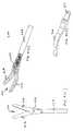
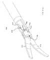
- FIG. 1illustrates a perspective view of a laparoscopic view of a surgical instrument of the prior art
- FIG. 2illustrates a side cutaway view of a tool mechanism of the surgical instrument of FIG. 1 in the open position
- FIG. 3is an exploded perspective view of FIG. 2 ;
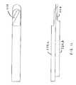
- FIGS. 4( a )- 4 ( c )illustrate a perspective view of a laparoscopic surgical instrument of the invention, a perspective view of a blade or tip of the tool mechanism of the invention, and a side view of FIG. 4( a ), respectively;
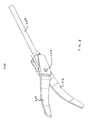
- FIG. 5illustrates a perspective view of an assembled surgical instrument of the invention having mobile tips and an actuation rod
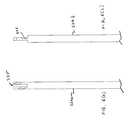
- FIGS. 6( a ) and 6 ( b )illustrate a fork actuation rod and a tongue actuation rod of the invention, respectively;
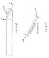
- FIGS. 7( a ) and 7 ( b )illustrate a perspective view and a side view of the fork actuation rod having slots on both sides of the fork end;
- FIGS. 7( c ) and 7 ( d )illustrate a perspective view and a side view of an actuation rod having a slot with an open end in accordance with another aspect of the invention
- FIGS. 7( e ) and 7 ( f )illustrate a perspective view and a side view of an actuation rod having a curved slot in accordance with another aspect of the invention
- FIGS. 8( a ) and 8 ( b )illustrate a side view and a cross-section view of an actuation rod having an angled slot in accordance with another aspect of the invention
- FIG. 8( c )illustrates a slot in an actuation rod having a detent or elevation shift to temporarily lock or ratchet the tips into a desired position in accordance with another aspect of the invention
- FIG. 8( d )illustrates a slot in an actuation rod having a locking mechanism in accordance with another aspect of the invention
- FIG. 9illustrates a perspective view of an assembled surgical instrument having a fixed tip and a mobile tip in accordance with another aspect of the invention.
- FIGS. 10( a ) and 10 ( b )illustrate perspective views of a surgical instrument having an actuation rod with a vertical slot to hold a floating drive pin in accordance with another aspect of the invention
- FIG. 11illustrates an actuation rod that is split into at least two pieces to provide independent motion to the tips in accordance with another aspect of the invention.
- FIG. 12illustrates an outer tube or shaft having slots to actuate the pins in the tips of a surgical instrument in accordance with another aspect of the invention.
- FIG. 1there is shown a perspective view of a laparoscopic surgical instrument 100 of the prior art as shown in U.S. Pat. No. 5,626,609, which is incorporated herein by reference.
- the surgical instrument 100typically comprises a handle assembly 10 having a fixed handle 12 and a pivoting handle 14 . Extending from the handle assembly 10 is a shaft assembly 20 comprising an outer tube 22 and an inner actuation rod 24 .
- the actuation rod 24slides in the outer tube 20 in a coaxial relationship.
- the outer tube 22may be secured to the fixed handle 12
- the actuation rod 24may be secured to the pivoting handle 14 .
- a tool mechanism 30Attached at a distal end of the shaft assembly 20 is a tool mechanism 30 , which comprises of a lower jaw 32 and an upper jaw 34 .
- the tool mechanism 30is connected to the shaft assembly 20 at pivot point 36 through linkage mechanism 40 .
- linkage mechanism 40is actuated to pivot jaws 32 and 34 about pivot point 36 to open and close the jaws.
- a tool mechanism 30 a of the prior artwhich includes, for example, a first scissor blade 32 a and a second scissor blade 34 a .
- a housing member 50is attached to the outer tube 22
- the tool mechanism 30 ais attached to the housing member 50 .
- the actuation rod 24slides through the outer tube 22 towards the tool mechanism 30 a .
- scissor blades 32 a , 34 aare provided with cam slots 38 and 39 , respectively, which slots accept a bearing post 60 which is attached to inner rod 24 .
- this tool mechanism 30 ais when the blades 32 a , 34 a are open, the tail end of the blades pass through slot 70 in housing member 50 to allow the blades to open. That is, the tail end of the blades 32 a , 34 a extend out beyond the outside diameter of the surgical instrument and look like “wings.” This may be a problem for the user as they can catch or interfere on tissue or other devices during use.
- the wingscan stretch and deform the plastic shrink tubing that is used to insulate the shaft assembly 20 .
- thiscan be problematic in that when the instrument is withdrawn from a trocar after a procedure, the deformed tubing may not relax and it may catch on the end of the cannula, thereby pulling the trocar out of the patient.
- a surgical instrument 200in accordance with a first aspect of the invention having a tool mechanism 210 including a first blade or tip 212 and a second blade or tip 214 , each of which has a pin 218 and 216 , respectively, formed at the proximal end.
- the pins 218 , 216are fixed, typically by welding, to blades or tips 212 , 214 and extend outwardly of the surface of the back end of the blades or tips 212 , 214 .
- the blades or tips 212 , 214are overlapped in a scissors configuration and are held in a pivotal relationship with an outer tube by a common pin 220 .
- a novel feature of the inventionis it includes the tool mechanism 210 that interacts with a slotted actuation rod 224 as further explained below. It is appreciated that because the blades or tips 212 , 214 include pins 218 , 216 , rather than slots, much area is not needed on the back ends. This is beneficial because the “wingspan” of the blades or tips 212 , 214 when opened is minimized if not eliminated. In addition, the overall strength of the blades or tips 212 , 214 and the rod 224 is maximized because both the rod and the blades are integral or are single piece components.
- the fork actuation rod 224can be formed in a number of different ways.
- the desired featurescan be machined from a solid rod or tube of a desired diameter.
- a strip of metalcan be stamped with the desired slots at the end, then the tube can be rolled into a particular diameter where the slotted end can form a “fork”.
- the fork features at the end of the actuation rodcan be overmolded onto a shaft to provide a cost effective component.
- the tongue actuation rodit can be formed in a similar way to the fork actuation rod. More specifically, machining the detail in the tip is an option as is overmolding the detail.
- the end of the actuation rodcan also be formed as a separate part, i.e., molded, machined, cast, MIM, etc., with the feature detail in it and then attached to a standard length shaft by means of a thread, snap, adhesive, welding process or some other attachment method.
- FIG. 5there is shown a perspective view of the tool mechanism 210 of FIG. 4 being connected to the actuation rod 224 .
- the blades or tips 212 , 214can be formed from conventional stamping and then heat treated.
- the blades or tips 212 , 214can be formed from a blank of pre-hardened material and then EDM cut, waterjet cut, laser cut or even machined to obtain the final shape.
- pins 218 , 216 in the back ends of the blades or tips 212 , 214can be formed directly onto the blades or pins themselves, or they can be added after the pins have been manufactured.
- the pins 218 , 216can be locked in any one or a combination of the following ways: press-fitted, swaged, threaded and/or welded.
- a multitude of processescan be used.
- a sheet of materialcan be machined to include a pivot hole as well as the pin.
- the sheetcan then be heat treated and sent to a form grinder, which can grind one profile of the blade or tip.
- the ground platecan then be sent to be EDM cut and the second profile can be cut out. This type of process can yield numbers components, with the drive pin integrally located, with relatively low cost.
- MIMmetal injection molding
- PMpowder metallurgy
- the “wingspan” of the bladescan be reduced or eliminated because the back end does not need to endcase the slot, but rather a small pin which minimizes the chance of catching on tissue, other instruments or suture.
- the end of the actuation rodwhich can be a fork design 224 a or a tongue design 224 b .
- a through slot 226can be formed on each side of the rod 224 a .
- the back end of the blades or tipscan be inserted into the rod where the pin of the first blade or tip can be locked into the first slot and the pin of the second blade or tip can be locked into the opposing second slot.
- the blades or tipscan be fixed by a common pivot point on the outer tube or shaft. When the actuation rod is moved in one direction, the blades or tips will cam via the pins and the slots 226 .
- the pin that locks each blade or tip into the shaftcan be integral to the blades or tips or they can be separate components.
- the tongue design 224 bcan include a slot 226 on each side of the tongue as further discussed below.
- FIGS. 7( a ) and 7 ( b )there are shown a perspective view and a side view of the actuation rod 224 incorporating slots 226 on both sides of the tongue end, respectively.
- the blades or tipscan have pins on the back end that nest in the slots of the rod.
- the rodmay be pushed forward or pulled backwards to cam the blades or tips, which are pivoted by a common pivot point that is attached to the outer tube or shaft.
- the slots 226can include an open or closed end slot (or combination of both) as desired.
- FIGS. 7( e ) and 7 ( f )illustrate an actuation rod having a curved slot in accordance with another aspect of the invention. It is appreciated that as the jaw providing the blades or tips of the invention articulates a pivot point, the distance between the pin and slot and the hinge vary depending on the actuation rod position. Accordingly, the curved slot of the invention can be used to compensate for this phenomenon and provide for a more linear relation between the actuation rod and the jaw motion. For example, the slot can be shaped to provide for more control as the blades or tips are nearing the closed position, and greater acceleration as the blades or tips are near the opened position. With this aspect, the instrument can be tuned to provide the desired instrument control and user feedback.
- a slot 226 b for the tonguecan be formed such that it has an angle to it.
- the depth of the slot 226 b at one end (‘B’) 227may be deeper or shallower than at the other end (‘A’) 228 .
- FIG. 8( c )there is shown a slot 226 c having a detent or elevation shift 229 to temporarily “lock” or “ratchet” the blade or tip into a desired position without affecting the linear motion of the jaws relative to the handle actuation.
- FIG. 8( d )illustrates that a slot 226 d can also be formed with different cross sections, e.g., slot 226 d having a locking mechanism with a dovetail profile 230 . With this embodiment, the mating pin on the blades or tips can match the slot to “lock” it in.
- both blades or tips 212 , 214do not need to be mobile. That is, one blade 212 may be fixed while the other blade 214 may actuate.
- the mobile blade 214may contain a pin 300 and an actuation rod 302 that would contain only one slot to actuate the blade 214 .
- FIGS. 10( a ) and 10 ( b )illustrate a surgical instrument 400 providing a floating drive pin 402 in an actuation rod 410 .
- the actuation rod 410includes a vertical slot 404 to allow the drive pin 402 to float in.
- the drive pin 402is positioned through slots 406 , 408 of blades or tips 412 , 414 , respectively, and is located in the actuation rod slot.
- An outer shaft tip 416has a floating pin slot 418 from the tip in.
- the floating drive pin 402slides in this slot and is contained therein.
- a pivot pin 420is located at the tip of the shaft to lock the tip assembly in place. Referring to FIG.
- the slots or channels 226can be of any of the above-described design, however, the actuation rod is split into a plurality of multiple pieces 224 c , 224 d to provide independent motion to the blades or tips. This would be useful if the blades or tips need to be articulated at different speeds, or over different distances.
- FIG. 12there is shown another aspect of the invention where the slot or channel is located in an outer shaft 524 rather in the actuation rod.
- the blades or tips 512 , 514are similar to those of the previous design, except pin 516 of blade 512 , for example, extends to the outer shaft 524 , which includes slots 518 to receive pins 516 , 520 of blades or tips 512 , 514 , respectively.
- blades or tips 512 , 514are actuated by rotating the outer shaft 524 , which cause pins 516 , 520 to cam along the slots 518 in the outer shaft 524 and actuate the blades 512 , 514 open and closed.
- the outer shaft 524can also be made up of multiple pieces and can include a channel rather than a through slot.
Landscapes
- Health & Medical Sciences (AREA)
- Surgery (AREA)
- Life Sciences & Earth Sciences (AREA)
- Medical Informatics (AREA)
- Animal Behavior & Ethology (AREA)
- Engineering & Computer Science (AREA)
- Biomedical Technology (AREA)
- Heart & Thoracic Surgery (AREA)
- Veterinary Medicine (AREA)
- Molecular Biology (AREA)
- Nuclear Medicine, Radiotherapy & Molecular Imaging (AREA)
- General Health & Medical Sciences (AREA)
- Public Health (AREA)
- Orthopedic Medicine & Surgery (AREA)
- Pathology (AREA)
- Dentistry (AREA)
- Oral & Maxillofacial Surgery (AREA)
- Ophthalmology & Optometry (AREA)
- Surgical Instruments (AREA)
Abstract
Description
- (1) The back end of each blade or tip is reduced in area so that during full deflection, very little or no part of the blade or tip extends beyond the outside diameter of the outer tube or shaft. This ensures that nothing catches on the blades or tips during grasper use and the shrink tubing found on scissors would not be deformed. This can be done because the area for the slots is not needed;
- (2) The usable area for the drive slots on the blade or tip of the actuation rod is maximized to the overall diameter of the outer tube or shaft which provides additional leverage to the blades or tips; and
- (3) If channels are used on the actuation rod, the depth of the channels can be varied such that increased tension can be placed on the blades during actuation.
Claims (14)
Priority Applications (1)
| Application Number | Priority Date | Filing Date | Title |
|---|---|---|---|
| US12/547,219US8114120B2 (en) | 2004-02-27 | 2009-08-25 | System and method for actuating a laparoscopic surgical instrument |
Applications Claiming Priority (3)
| Application Number | Priority Date | Filing Date | Title |
|---|---|---|---|
| US54874704P | 2004-02-27 | 2004-02-27 | |
| US11/059,806US7578832B2 (en) | 2004-02-27 | 2005-02-17 | System for actuating a laparoscopic surgical instrument |
| US12/547,219US8114120B2 (en) | 2004-02-27 | 2009-08-25 | System and method for actuating a laparoscopic surgical instrument |
Related Parent Applications (1)
| Application Number | Title | Priority Date | Filing Date |
|---|---|---|---|
| US11/059,806ContinuationUS7578832B2 (en) | 2004-02-27 | 2005-02-17 | System for actuating a laparoscopic surgical instrument |
Publications (2)
| Publication Number | Publication Date |
|---|---|
| US20090318954A1 US20090318954A1 (en) | 2009-12-24 |
| US8114120B2true US8114120B2 (en) | 2012-02-14 |
Family
ID=34960959
Family Applications (2)
| Application Number | Title | Priority Date | Filing Date |
|---|---|---|---|
| US11/059,806Active2026-01-28US7578832B2 (en) | 2004-02-27 | 2005-02-17 | System for actuating a laparoscopic surgical instrument |
| US12/547,219Expired - Fee RelatedUS8114120B2 (en) | 2004-02-27 | 2009-08-25 | System and method for actuating a laparoscopic surgical instrument |
Family Applications Before (1)
| Application Number | Title | Priority Date | Filing Date |
|---|---|---|---|
| US11/059,806Active2026-01-28US7578832B2 (en) | 2004-02-27 | 2005-02-17 | System for actuating a laparoscopic surgical instrument |
Country Status (5)
| Country | Link |
|---|---|
| US (2) | US7578832B2 (en) |
| EP (2) | EP2022417B1 (en) |
| JP (1) | JP2007525285A (en) |
| DE (2) | DE602005020534D1 (en) |
| WO (1) | WO2005092216A1 (en) |
Cited By (2)
| Publication number | Priority date | Publication date | Assignee | Title |
|---|---|---|---|---|
| US20130066230A1 (en)* | 2011-09-13 | 2013-03-14 | Changqing Li | Single piece biopsy forceps |
| US20130190793A1 (en)* | 2011-07-11 | 2013-07-25 | Herbert D. Huddleston | Method and apparatus for minimally invasive skin and soft-tissue incisions |
Families Citing this family (127)
| Publication number | Priority date | Publication date | Assignee | Title |
|---|---|---|---|---|
| US7559893B2 (en) | 1998-12-01 | 2009-07-14 | Atropos Limited | Wound retractor device |
| US6254534B1 (en) | 1999-10-14 | 2001-07-03 | Atropos Limited | Retractor |
| US7998068B2 (en) | 1998-12-01 | 2011-08-16 | Atropos Limited | Instrument access device |
| US7537564B2 (en) | 1998-12-01 | 2009-05-26 | Atropos Limited | Wound retractor device |
| CN100512766C (en) | 1998-12-01 | 2009-07-15 | 阿特波斯有限公司 | A surgical device for retracting and/or sealing an incision |
| US7540839B2 (en) | 1999-10-14 | 2009-06-02 | Atropos Limited | Wound retractor |
| JP5190169B2 (en) | 2000-10-19 | 2013-04-24 | アプライド メディカル リソーシーズ コーポレイション | Surgical access instruments and methods |
| EP2422829B1 (en) | 2001-08-14 | 2013-03-06 | Applied Medical Resources Corporation | Surgical access sealing apparatus |
| US6958037B2 (en) | 2001-10-20 | 2005-10-25 | Applied Medical Resources Corporation | Wound retraction apparatus and method |
| EP2343032B1 (en) | 2002-06-05 | 2012-05-09 | Applied Medical Resources Corporation | Wound retractor |
| US9271753B2 (en) | 2002-08-08 | 2016-03-01 | Atropos Limited | Surgical device |
| DE60314464T2 (en) | 2002-09-19 | 2008-02-14 | Atropos Ltd., Bray | SURGICAL WOUND RETRACTOR |
| US20050020884A1 (en) | 2003-02-25 | 2005-01-27 | Hart Charles C. | Surgical access system |
| US7468041B2 (en)* | 2003-06-26 | 2008-12-23 | Depuy Products, Inc. | Modular surgical instrument with reciprocable implement |
| CA2533204A1 (en) | 2003-08-06 | 2005-02-17 | Applied Medical Resources Corporation | Surgical device with tack-free gel and method of manufacture |
| US7163510B2 (en) | 2003-09-17 | 2007-01-16 | Applied Medical Resources Corporation | Surgical instrument access device |
| US8114107B2 (en)* | 2003-11-05 | 2012-02-14 | Applied Medical Resources Corporation | Laparoscopic scissor blades |
| JP2009501045A (en) | 2005-07-15 | 2009-01-15 | アトロポス・リミテッド | Wound retractor |
| AU2006304141B2 (en) | 2005-10-14 | 2012-07-05 | Applied Medical Resources Corporation | Gel cap for wound retractor |
| US7655004B2 (en) | 2007-02-15 | 2010-02-02 | Ethicon Endo-Surgery, Inc. | Electroporation ablation apparatus, system, and method |
| US7815662B2 (en) | 2007-03-08 | 2010-10-19 | Ethicon Endo-Surgery, Inc. | Surgical suture anchors and deployment device |
| US8075572B2 (en) | 2007-04-26 | 2011-12-13 | Ethicon Endo-Surgery, Inc. | Surgical suturing apparatus |
| US8100922B2 (en) | 2007-04-27 | 2012-01-24 | Ethicon Endo-Surgery, Inc. | Curved needle suturing tool |
| EP2146644A4 (en) | 2007-05-11 | 2012-07-18 | Applied Med Resources | Surgical retractor |
| WO2008141291A1 (en) | 2007-05-11 | 2008-11-20 | Applied Medical Resources Corporation | Surgical retractor with gel pad |
| WO2008149332A1 (en) | 2007-06-05 | 2008-12-11 | Atropos Limited | An instrument access device |
| US8657740B2 (en) | 2007-06-05 | 2014-02-25 | Atropos Limited | Instrument access device |
| US8579897B2 (en) | 2007-11-21 | 2013-11-12 | Ethicon Endo-Surgery, Inc. | Bipolar forceps |
| US8262655B2 (en) | 2007-11-21 | 2012-09-11 | Ethicon Endo-Surgery, Inc. | Bipolar forceps |
| US8568410B2 (en) | 2007-08-31 | 2013-10-29 | Ethicon Endo-Surgery, Inc. | Electrical ablation surgical instruments |
| US20090112059A1 (en) | 2007-10-31 | 2009-04-30 | Nobis Rudolph H | Apparatus and methods for closing a gastrotomy |
| US8480657B2 (en) | 2007-10-31 | 2013-07-09 | Ethicon Endo-Surgery, Inc. | Detachable distal overtube section and methods for forming a sealable opening in the wall of an organ |
| CA2711116C (en) | 2008-01-22 | 2017-08-29 | Applied Medical Resources Corporation | Surgical instrument access device |
| US8262680B2 (en) | 2008-03-10 | 2012-09-11 | Ethicon Endo-Surgery, Inc. | Anastomotic device |
| US8277475B2 (en) | 2008-05-09 | 2012-10-02 | Applied Medical Resources Corporation | Laparoscopic scissors |
| US8652150B2 (en) | 2008-05-30 | 2014-02-18 | Ethicon Endo-Surgery, Inc. | Multifunction surgical device |
| US8317806B2 (en) | 2008-05-30 | 2012-11-27 | Ethicon Endo-Surgery, Inc. | Endoscopic suturing tension controlling and indication devices |
| US8070759B2 (en) | 2008-05-30 | 2011-12-06 | Ethicon Endo-Surgery, Inc. | Surgical fastening device |
| US8679003B2 (en) | 2008-05-30 | 2014-03-25 | Ethicon Endo-Surgery, Inc. | Surgical device and endoscope including same |
| US8771260B2 (en) | 2008-05-30 | 2014-07-08 | Ethicon Endo-Surgery, Inc. | Actuating and articulating surgical device |
| US8114072B2 (en) | 2008-05-30 | 2012-02-14 | Ethicon Endo-Surgery, Inc. | Electrical ablation device |
| US8906035B2 (en) | 2008-06-04 | 2014-12-09 | Ethicon Endo-Surgery, Inc. | Endoscopic drop off bag |
| US8403926B2 (en) | 2008-06-05 | 2013-03-26 | Ethicon Endo-Surgery, Inc. | Manually articulating devices |
| US8361112B2 (en) | 2008-06-27 | 2013-01-29 | Ethicon Endo-Surgery, Inc. | Surgical suture arrangement |
| US8888792B2 (en) | 2008-07-14 | 2014-11-18 | Ethicon Endo-Surgery, Inc. | Tissue apposition clip application devices and methods |
| US8262563B2 (en) | 2008-07-14 | 2012-09-11 | Ethicon Endo-Surgery, Inc. | Endoscopic translumenal articulatable steerable overtube |
| US8211125B2 (en) | 2008-08-15 | 2012-07-03 | Ethicon Endo-Surgery, Inc. | Sterile appliance delivery device for endoscopic procedures |
| US8529563B2 (en) | 2008-08-25 | 2013-09-10 | Ethicon Endo-Surgery, Inc. | Electrical ablation devices |
| US8241204B2 (en) | 2008-08-29 | 2012-08-14 | Ethicon Endo-Surgery, Inc. | Articulating end cap |
| US8480689B2 (en) | 2008-09-02 | 2013-07-09 | Ethicon Endo-Surgery, Inc. | Suturing device |
| US8409200B2 (en) | 2008-09-03 | 2013-04-02 | Ethicon Endo-Surgery, Inc. | Surgical grasping device |
| US8114119B2 (en) | 2008-09-09 | 2012-02-14 | Ethicon Endo-Surgery, Inc. | Surgical grasping device |
| US8337394B2 (en) | 2008-10-01 | 2012-12-25 | Ethicon Endo-Surgery, Inc. | Overtube with expandable tip |
| CA2739910C (en) | 2008-10-13 | 2017-06-06 | Applied Medical Resources Corporation | Single port access system |
| US8157834B2 (en) | 2008-11-25 | 2012-04-17 | Ethicon Endo-Surgery, Inc. | Rotational coupling device for surgical instrument with flexible actuators |
| US8172772B2 (en) | 2008-12-11 | 2012-05-08 | Ethicon Endo-Surgery, Inc. | Specimen retrieval device |
| US8361066B2 (en) | 2009-01-12 | 2013-01-29 | Ethicon Endo-Surgery, Inc. | Electrical ablation devices |
| US8828031B2 (en) | 2009-01-12 | 2014-09-09 | Ethicon Endo-Surgery, Inc. | Apparatus for forming an anastomosis |
| US9226772B2 (en) | 2009-01-30 | 2016-01-05 | Ethicon Endo-Surgery, Inc. | Surgical device |
| US8252057B2 (en) | 2009-01-30 | 2012-08-28 | Ethicon Endo-Surgery, Inc. | Surgical access device |
| US8037591B2 (en) | 2009-02-02 | 2011-10-18 | Ethicon Endo-Surgery, Inc. | Surgical scissors |
| US8375955B2 (en) | 2009-02-06 | 2013-02-19 | Atropos Limited | Surgical procedure |
| US20100298853A1 (en)* | 2009-05-22 | 2010-11-25 | Slater Charles R | Endoscopic Instrument Having Rotatably Mounted End Effector Assembly |
| US8690909B2 (en)* | 2009-05-22 | 2014-04-08 | Charles R. Slater | Endoscopic instrument with bi-laterally widened cam-slot at end effector |
| US20100298854A1 (en)* | 2009-05-22 | 2010-11-25 | Slater Charles R | Endoscopic Instrument with Control Member Having Decreasing Torsional and Flexural Stiffness Along Its Length |
| US9277932B2 (en)* | 2009-05-22 | 2016-03-08 | Slatr Surgical Holdings Llc | Endoscopic scissors instrument with friction enhancing tissue stops |
| US9566082B2 (en)* | 2009-05-22 | 2017-02-14 | Slatr Surgical Holdings Llc | Endoscopic instrument |
| BRPI1012156A2 (en)* | 2009-05-22 | 2016-04-05 | Apollo Endosurgery Inc | endoscopic instrument. |
| US20110029010A1 (en)* | 2009-07-28 | 2011-02-03 | Salvatore Castro | Flexible dissecting forceps |
| WO2011033495A1 (en) | 2009-09-17 | 2011-03-24 | Atropos Limited | An instrument access device |
| US20110098704A1 (en) | 2009-10-28 | 2011-04-28 | Ethicon Endo-Surgery, Inc. | Electrical ablation devices |
| US8608652B2 (en) | 2009-11-05 | 2013-12-17 | Ethicon Endo-Surgery, Inc. | Vaginal entry surgical devices, kit, system, and method |
| US8496574B2 (en) | 2009-12-17 | 2013-07-30 | Ethicon Endo-Surgery, Inc. | Selectively positionable camera for surgical guide tube assembly |
| US8353487B2 (en) | 2009-12-17 | 2013-01-15 | Ethicon Endo-Surgery, Inc. | User interface support devices for endoscopic surgical instruments |
| US9028483B2 (en) | 2009-12-18 | 2015-05-12 | Ethicon Endo-Surgery, Inc. | Surgical instrument comprising an electrode |
| US8506564B2 (en) | 2009-12-18 | 2013-08-13 | Ethicon Endo-Surgery, Inc. | Surgical instrument comprising an electrode |
| US9005198B2 (en) | 2010-01-29 | 2015-04-14 | Ethicon Endo-Surgery, Inc. | Surgical instrument comprising an electrode |
| US9339341B2 (en)* | 2010-02-08 | 2016-05-17 | Intuitive Surgical Operations, Inc. | Direct pull surgical gripper |
| USD648434S1 (en)* | 2010-05-07 | 2011-11-08 | Karl Storz Gmbh & Co. Kg | Forceps inserts for laparoscopic Procedures |
| USD641873S1 (en)* | 2010-06-09 | 2011-07-19 | Karl Storz Gmbh & Co. Kg | Forceps for transanal videoendoscopic rectal surgery |
| USD641872S1 (en)* | 2010-06-09 | 2011-07-19 | Karl Storz Gmbh & Co. Kg | Forceps for transanal videoendoscopic rectal surgery |
| USD641874S1 (en)* | 2010-06-09 | 2011-07-19 | Karl Storz Gmbh & Co. Kg | Forceps for transanal videoendoscopic rectal surgery |
| JP5704858B2 (en)* | 2010-08-24 | 2015-04-22 | Hoya株式会社 | Endoscopy forceps |
| US8523893B2 (en) | 2010-09-30 | 2013-09-03 | Applied Medical Resources Corporation | Laparoscopic scissors |
| US9289115B2 (en) | 2010-10-01 | 2016-03-22 | Applied Medical Resources Corporation | Natural orifice surgery system |
| JP6396657B2 (en) | 2010-10-01 | 2018-09-26 | アプライド メディカル リソーシーズ コーポレイション | Natural orifice surgery system |
| US10092291B2 (en) | 2011-01-25 | 2018-10-09 | Ethicon Endo-Surgery, Inc. | Surgical instrument with selectively rigidizable features |
| US9254169B2 (en) | 2011-02-28 | 2016-02-09 | Ethicon Endo-Surgery, Inc. | Electrical ablation devices and methods |
| US9233241B2 (en) | 2011-02-28 | 2016-01-12 | Ethicon Endo-Surgery, Inc. | Electrical ablation devices and methods |
| US9314620B2 (en) | 2011-02-28 | 2016-04-19 | Ethicon Endo-Surgery, Inc. | Electrical ablation devices and methods |
| US9049987B2 (en) | 2011-03-17 | 2015-06-09 | Ethicon Endo-Surgery, Inc. | Hand held surgical device for manipulating an internal magnet assembly within a patient |
| US8758236B2 (en) | 2011-05-10 | 2014-06-24 | Applied Medical Resources Corporation | Wound retractor |
| EP2522280B1 (en) | 2011-05-11 | 2016-03-02 | University Of Dundee | Medical instrument for grasping an object, in particular a needle holder |
| US9636169B2 (en)* | 2011-09-19 | 2017-05-02 | Covidien Lp | Electrosurgical instrument |
| US8986199B2 (en) | 2012-02-17 | 2015-03-24 | Ethicon Endo-Surgery, Inc. | Apparatus and methods for cleaning the lens of an endoscope |
| US20150327751A1 (en)* | 2012-04-25 | 2015-11-19 | Industry-University Cooperation Foundation Hanyang University Erica Campus | Bendable end-effector |
| US9427255B2 (en) | 2012-05-14 | 2016-08-30 | Ethicon Endo-Surgery, Inc. | Apparatus for introducing a steerable camera assembly into a patient |
| US9078662B2 (en) | 2012-07-03 | 2015-07-14 | Ethicon Endo-Surgery, Inc. | Endoscopic cap electrode and method for using the same |
| WO2014008492A1 (en)* | 2012-07-06 | 2014-01-09 | Intuitive Surgical Operations, Inc. | Remotely actuated surgical gripper with seize resistance |
| US9545290B2 (en) | 2012-07-30 | 2017-01-17 | Ethicon Endo-Surgery, Inc. | Needle probe guide |
| US10314649B2 (en) | 2012-08-02 | 2019-06-11 | Ethicon Endo-Surgery, Inc. | Flexible expandable electrode and method of intraluminal delivery of pulsed power |
| US9572623B2 (en) | 2012-08-02 | 2017-02-21 | Ethicon Endo-Surgery, Inc. | Reusable electrode and disposable sheath |
| US9277957B2 (en) | 2012-08-15 | 2016-03-08 | Ethicon Endo-Surgery, Inc. | Electrosurgical devices and methods |
| US10098527B2 (en) | 2013-02-27 | 2018-10-16 | Ethidcon Endo-Surgery, Inc. | System for performing a minimally invasive surgical procedure |
| US20140257416A1 (en)* | 2013-03-06 | 2014-09-11 | Nathan Meyer | Percutaneous rod inserter |
| JP2016512725A (en) | 2013-03-15 | 2016-05-09 | アプライド メディカル リソーシーズ コーポレイション | Mechanical gel surgical access instrument |
| WO2014172676A1 (en)* | 2013-04-20 | 2014-10-23 | Apollo Endosurgery, Inc. | Flexible endoscopic torqueable devices |
| CN103445858B (en)* | 2013-09-13 | 2015-09-16 | 安徽奥弗医疗设备科技股份有限公司 | A kind of heat setting cutter |
| CN103445862B (en)* | 2013-09-13 | 2015-11-11 | 安徽奥弗医疗设备科技股份有限公司 | A kind of connecting device of heat setting cutter gripper jaw |
| EP3169510B1 (en) | 2014-07-18 | 2018-10-03 | Applied Medical Resources Corporation | Method for manufacturing gels having permanent tack free coatings |
| KR20240172766A (en) | 2014-08-15 | 2024-12-10 | 어플라이드 메디컬 리소시스 코포레이션 | Natural orifice surgery system |
| USD761961S1 (en) | 2014-11-07 | 2016-07-19 | Karl Storz Gmbh & Co. Kg | Forceps insert for laparoscopic procedures |
| WO2016085930A2 (en) | 2014-11-25 | 2016-06-02 | Applied Medical Resources Corporation | Circumferential wound retraction with support and guidance structures |
| USD789535S1 (en) | 2015-06-17 | 2017-06-13 | Karl Storz Gmbh & Co. Kg | Shaft instrument for shaving tissue |
| USD791321S1 (en) | 2015-06-17 | 2017-07-04 | Karl Storz Gmbh & Co. Kg | Shaft instrument for shaving tissue |
| US10368908B2 (en) | 2015-09-15 | 2019-08-06 | Applied Medical Resources Corporation | Surgical robotic access system |
| WO2017062850A2 (en) | 2015-10-07 | 2017-04-13 | Applied Medical Resources Corporation | Wound retractor with multi-segment outer ring |
| AU2017324450B2 (en) | 2016-09-12 | 2022-09-29 | Applied Medical Resources Corporation | Surgical robotic access system for irregularly shaped robotic actuators and associated robotic surgical instruments |
| US10925628B2 (en)* | 2017-09-18 | 2021-02-23 | Novuson Surgical, Inc. | Tissue engagement apparatus for theapeutic ultrasound apparatus and method |
| US20190254644A1 (en)* | 2018-02-22 | 2019-08-22 | Boston Scientific Limited | Biopsy forceps with cam mechanism |
| US11612447B2 (en) | 2018-07-19 | 2023-03-28 | Intuitive Surgical Operations, Inc. | Medical devices having three tool members |
| US11103245B2 (en)* | 2018-12-31 | 2021-08-31 | Cilag Gmbh International | Knife for surgical stapler and associated method of manufacture with MIM and hip |
| CN110051425B (en)* | 2019-05-15 | 2023-11-14 | 成都五义医疗科技有限公司 | Improved slender shaft assembly and surgical instrument |
| CN113952025B (en)* | 2019-05-15 | 2023-05-26 | 成都五义医疗科技有限公司 | Slender shaft assembly comprising static tube assembly and movable rod assembly for minimally invasive surgery |
| US11191586B2 (en)* | 2019-07-02 | 2021-12-07 | Jamison Alexander | Removable tip for use with electrosurgical devices |
| EP4027897B1 (en) | 2020-02-03 | 2025-04-16 | Boston Scientific Limited | Biopsy forceps with tissue piercing member |
| DK181495B1 (en)* | 2021-05-10 | 2024-03-12 | Flexlogical Aps | End effector for minimally invasive surgery |
Citations (19)
| Publication number | Priority date | Publication date | Assignee | Title |
|---|---|---|---|---|
| US5176699A (en) | 1991-06-05 | 1993-01-05 | Harold Markham | Surgical device with double jaw actuation |
| EP0537574A2 (en) | 1991-10-18 | 1993-04-21 | United States Surgical Corporation | Endoscopic surgical instrument |
| US5219357A (en) | 1990-05-31 | 1993-06-15 | Tnco, Inc. | Micro-instrument |
| US5275615A (en)* | 1992-09-11 | 1994-01-04 | Anthony Rose | Medical instrument having gripping jaws |
| US5281220A (en) | 1992-01-13 | 1994-01-25 | Blake Joseph W Iii | Endoscopic instrument |
| US5383888A (en) | 1992-02-12 | 1995-01-24 | United States Surgical Corporation | Articulating endoscopic surgical apparatus |
| US5496347A (en) | 1993-03-30 | 1996-03-05 | Olympus Optical Co., Ltd. | Surgical instrument |
| US5496317A (en) | 1993-05-04 | 1996-03-05 | Gyrus Medical Limited | Laparoscopic surgical instrument |
| US5626609A (en) | 1990-10-05 | 1997-05-06 | United States Surgical Corporation | Endoscopic surgical instrument |
| US5700276A (en) | 1995-06-10 | 1997-12-23 | Olympus Winter & Ibe Gmbh | Surgical forceps |
| US5728113A (en) | 1994-10-07 | 1998-03-17 | United States Surgical Corporation | Endoscopic vascular suturing apparatus |
| US5810879A (en) | 1997-02-27 | 1998-09-22 | Microline, Inc. | Laparoscopic instrument |
| US5849022A (en) | 1994-07-29 | 1998-12-15 | Olympus Optical Co., Ltd. | Medical instrument for use in combination with endoscopes |
| US5893874A (en)* | 1997-02-07 | 1999-04-13 | Smith & Nephew, Inc. | Surgical instrument |
| DE20001492U1 (en) | 2000-01-27 | 2000-06-21 | Aesculap AG & Co. KG, 78532 Tuttlingen | Surgical tubular shaft instrument |
| US6228083B1 (en)* | 1997-11-14 | 2001-05-08 | Sherwood Services Ag | Laparoscopic bipolar electrosurgical instrument |
| DE20121161U1 (en) | 2001-01-31 | 2002-04-04 | Olympus Winter & Ibe Gmbh, 22045 Hamburg | Endoscopic instrument |
| US20020143358A1 (en)* | 2001-02-13 | 2002-10-03 | Domingo Nicanor A. | Method and apparatus for micro-dissection of vascular occlusions |
| DE20309774U1 (en) | 2003-06-20 | 2003-10-02 | Aesculap AG & Co. KG, 78532 Tuttlingen | Surgical instrument couple has a form/fit union with the power transmission link |
- 2005
- 2005-02-17EPEP08170110Apatent/EP2022417B1/ennot_activeCeased
- 2005-02-17DEDE602005020534Tpatent/DE602005020534D1/ennot_activeExpired - Lifetime
- 2005-02-17USUS11/059,806patent/US7578832B2/enactiveActive
- 2005-02-17WOPCT/US2005/005105patent/WO2005092216A1/enactiveApplication Filing
- 2005-02-17DEDE602005012482Tpatent/DE602005012482D1/ennot_activeExpired - Lifetime
- 2005-02-17JPJP2007500887Apatent/JP2007525285A/enactivePending
- 2005-02-17EPEP05713752Apatent/EP1718224B1/ennot_activeCeased
- 2009
- 2009-08-25USUS12/547,219patent/US8114120B2/ennot_activeExpired - Fee Related
Patent Citations (21)
| Publication number | Priority date | Publication date | Assignee | Title |
|---|---|---|---|---|
| US5219357A (en) | 1990-05-31 | 1993-06-15 | Tnco, Inc. | Micro-instrument |
| US5626609A (en) | 1990-10-05 | 1997-05-06 | United States Surgical Corporation | Endoscopic surgical instrument |
| US5176699A (en) | 1991-06-05 | 1993-01-05 | Harold Markham | Surgical device with double jaw actuation |
| EP0537574A2 (en) | 1991-10-18 | 1993-04-21 | United States Surgical Corporation | Endoscopic surgical instrument |
| US5281220A (en) | 1992-01-13 | 1994-01-25 | Blake Joseph W Iii | Endoscopic instrument |
| US5383888A (en) | 1992-02-12 | 1995-01-24 | United States Surgical Corporation | Articulating endoscopic surgical apparatus |
| US5607450A (en) | 1992-02-12 | 1997-03-04 | United States Surgical Corporation | Articulating endoscopic surgical apparatus |
| US5275615A (en)* | 1992-09-11 | 1994-01-04 | Anthony Rose | Medical instrument having gripping jaws |
| US5496347A (en) | 1993-03-30 | 1996-03-05 | Olympus Optical Co., Ltd. | Surgical instrument |
| US5496317A (en) | 1993-05-04 | 1996-03-05 | Gyrus Medical Limited | Laparoscopic surgical instrument |
| US5849022A (en) | 1994-07-29 | 1998-12-15 | Olympus Optical Co., Ltd. | Medical instrument for use in combination with endoscopes |
| US5728113A (en) | 1994-10-07 | 1998-03-17 | United States Surgical Corporation | Endoscopic vascular suturing apparatus |
| US5700276A (en) | 1995-06-10 | 1997-12-23 | Olympus Winter & Ibe Gmbh | Surgical forceps |
| US5893874A (en)* | 1997-02-07 | 1999-04-13 | Smith & Nephew, Inc. | Surgical instrument |
| US6007561A (en) | 1997-02-07 | 1999-12-28 | Smith & Nephew North America | Surgical instrument |
| US5810879A (en) | 1997-02-27 | 1998-09-22 | Microline, Inc. | Laparoscopic instrument |
| US6228083B1 (en)* | 1997-11-14 | 2001-05-08 | Sherwood Services Ag | Laparoscopic bipolar electrosurgical instrument |
| DE20001492U1 (en) | 2000-01-27 | 2000-06-21 | Aesculap AG & Co. KG, 78532 Tuttlingen | Surgical tubular shaft instrument |
| DE20121161U1 (en) | 2001-01-31 | 2002-04-04 | Olympus Winter & Ibe Gmbh, 22045 Hamburg | Endoscopic instrument |
| US20020143358A1 (en)* | 2001-02-13 | 2002-10-03 | Domingo Nicanor A. | Method and apparatus for micro-dissection of vascular occlusions |
| DE20309774U1 (en) | 2003-06-20 | 2003-10-02 | Aesculap AG & Co. KG, 78532 Tuttlingen | Surgical instrument couple has a form/fit union with the power transmission link |
Non-Patent Citations (7)
| Title |
|---|
| "Invitation to Pay Additional Fees", International Application No. PCT/US2005/005105, and communication relating to the "Results of the Partial International Search". |
| Co-Pending U.S. Appl. No. 10/976,505, filed Oct. 29, 2004. Title: Multiple-Angle Scissor Blade. |
| Co-Pending U.S. Appl. No. 11/334,027, filed Jan. 18, 2006. Title: Disposable Laparoscopic Instrument. |
| Co-Pending U.S. Appl. No. 11/345,964, filed Feb. 2, 2006. Title: Surgical Instrument With Removable Shaft Apparatus and Method. |
| Co-Pending U.S. Appl. No. 11/735,798, filed Apr. 16, 2007. Title: Laparoscopic Scissor Blade. |
| European Patent Office, European Search Report dated Dec. 17, 2008, for European Patent Application No. EP 08 17 0110. |
| International Search Report and Written Opinion of the International Searching Authority for PCT application No. PCt/US2005/005105, mailing date Aug. 23, 2005. |
Cited By (5)
| Publication number | Priority date | Publication date | Assignee | Title |
|---|---|---|---|---|
| US20130190793A1 (en)* | 2011-07-11 | 2013-07-25 | Herbert D. Huddleston | Method and apparatus for minimally invasive skin and soft-tissue incisions |
| US9089357B2 (en)* | 2011-07-11 | 2015-07-28 | Herbert D. Huddleston | Multi-functional double bladed surgical tool |
| US20130066230A1 (en)* | 2011-09-13 | 2013-03-14 | Changqing Li | Single piece biopsy forceps |
| US9456840B1 (en)* | 2012-05-01 | 2016-10-04 | Herbert D. Huddleston | Multi-functional double bladed surgical tool |
| US10299822B1 (en)* | 2012-05-01 | 2019-05-28 | Herbert D. Huddleston | Double bladed surgical tool in combination with a targeting guide |
Also Published As
| Publication number | Publication date |
|---|---|
| EP1718224A1 (en) | 2006-11-08 |
| JP2007525285A (en) | 2007-09-06 |
| US20050192598A1 (en) | 2005-09-01 |
| US7578832B2 (en) | 2009-08-25 |
| EP2022417A1 (en) | 2009-02-11 |
| DE602005020534D1 (en) | 2010-05-20 |
| DE602005012482D1 (en) | 2009-03-12 |
| EP1718224B1 (en) | 2009-01-21 |
| WO2005092216A1 (en) | 2005-10-06 |
| US20090318954A1 (en) | 2009-12-24 |
| EP2022417B1 (en) | 2010-04-07 |
Similar Documents
| Publication | Publication Date | Title |
|---|---|---|
| US8114120B2 (en) | System and method for actuating a laparoscopic surgical instrument | |
| JP4242044B2 (en) | Curved laparoscope with arc-shaped part of two kinds of curvature | |
| US5707392A (en) | Hermaphroditic stamped forceps jaw for disposable endoscopic biopsy forceps and method of making the same | |
| US20060161190A1 (en) | Disposable laparoscopic instrument | |
| US7105005B2 (en) | Arteriotomy scissors for minimally invasive surgical procedures | |
| EP0687446B1 (en) | Surgical incision members for endoscopic suturing apparatus | |
| US8568443B1 (en) | Surgical grapser tool and actuation mechanism | |
| US20170000483A1 (en) | Surgical instrument | |
| US9179929B2 (en) | Laparoscopic scissors | |
| US5275612A (en) | Insulating ferrule for disposable laparoscopic surgical instrument | |
| CN101156801A (en) | Grasping forceps mechanism | |
| WO1997013459A1 (en) | Stamped clevis for endoscopic instruments and method of making the same | |
| US8523893B2 (en) | Laparoscopic scissors | |
| KR20190117629A (en) | Jaw assembly and biopsy sample collection member for surgical instruments | |
| US20140005689A1 (en) | Suture cutter | |
| KR102724262B1 (en) | A soft tissue cutting tool having a self-locking, multi-position, and linearly actuated retractable blade or hook by a slide button. | |
| US20220151596A1 (en) | Locking Forceps | |
| JPH06315462A (en) | Scissors forceps for endoscope |
Legal Events
| Date | Code | Title | Description |
|---|---|---|---|
| AS | Assignment | Owner name:APPLIED MEDICAL RESOURCES CORPORATION, CALIFORNIA Free format text:ASSIGNMENT OF ASSIGNORS INTEREST;ASSIGNORS:JOHNSON, GARY M.;AHLBERG, RUSSELL E.;OKIHISA, DAVID;AND OTHERS;REEL/FRAME:023144/0358;SIGNING DATES FROM 20050215 TO 20050216 Owner name:APPLIED MEDICAL RESOURCES CORPORATION, CALIFORNIA Free format text:ASSIGNMENT OF ASSIGNORS INTEREST;ASSIGNORS:JOHNSON, GARY M.;AHLBERG, RUSSELL E.;OKIHISA, DAVID;AND OTHERS;SIGNING DATES FROM 20050215 TO 20050216;REEL/FRAME:023144/0358 | |
| ZAAA | Notice of allowance and fees due | Free format text:ORIGINAL CODE: NOA | |
| ZAAB | Notice of allowance mailed | Free format text:ORIGINAL CODE: MN/=. | |
| STCF | Information on status: patent grant | Free format text:PATENTED CASE | |
| AS | Assignment | Owner name:CITIBANK, N.A., TEXAS Free format text:SECURITY AGREEMENT;ASSIGNOR:APPLIED MEDICAL RESOURCES CORPORATION;REEL/FRAME:028115/0276 Effective date:20120417 | |
| FPAY | Fee payment | Year of fee payment:4 | |
| AS | Assignment | Owner name:JPMORGAN CHASE BANK, N.A., AS ADMINISTRATIVE AGENT, ILLINOIS Free format text:SECURITY INTEREST;ASSIGNOR:APPLIED MEDICAL RESOURCES CORPORATION;REEL/FRAME:042669/0725 Effective date:20170531 Owner name:JPMORGAN CHASE BANK, N.A., AS ADMINISTRATIVE AGENT Free format text:SECURITY INTEREST;ASSIGNOR:APPLIED MEDICAL RESOURCES CORPORATION;REEL/FRAME:042669/0725 Effective date:20170531 | |
| MAFP | Maintenance fee payment | Free format text:PAYMENT OF MAINTENANCE FEE, 8TH YEAR, LARGE ENTITY (ORIGINAL EVENT CODE: M1552); ENTITY STATUS OF PATENT OWNER: LARGE ENTITY Year of fee payment:8 | |
| AS | Assignment | Owner name:CITIBANK, N.A., TEXAS Free format text:SECURITY INTEREST;ASSIGNOR:APPLIED MEDICAL RESOURCES CORPORATION;REEL/FRAME:056683/0001 Effective date:20210625 | |
| AS | Assignment | Owner name:APPLIED MEDICAL RESOURCES CORPORATION, CALIFORNIA Free format text:RELEASE BY SECURED PARTY;ASSIGNOR:JPMORGAN CHASE BANK, N.A.;REEL/FRAME:056751/0169 Effective date:20210625 | |
| FEPP | Fee payment procedure | Free format text:MAINTENANCE FEE REMINDER MAILED (ORIGINAL EVENT CODE: REM.); ENTITY STATUS OF PATENT OWNER: LARGE ENTITY | |
| AS | Assignment | Owner name:BMO BANK N.A., AS ADMINISTRATIVE AGENT, CALIFORNIA Free format text:SECURITY INTEREST;ASSIGNOR:APPLIED MEDICAL RESOURCES CORPORATION;REEL/FRAME:066702/0123 Effective date:20240227 | |
| AS | Assignment | Owner name:APPLIED MEDICAL RESOURCES CORPORATION, CALIFORNIA Free format text:RELEASE BY SECURED PARTY;ASSIGNOR:CITIBANK N.A., AS ADMINISTRATIVE AGENT;REEL/FRAME:066796/0262 Effective date:20240129 Owner name:APPLIED MEDICAL RESOURCES CORPORATION, CALIFORNIA Free format text:RELEASE BY SECURED PARTY;ASSIGNOR:CITIBANK N.A., AS ADMINISTRATIVE AGENT;REEL/FRAME:066795/0595 Effective date:20240129 | |
| LAPS | Lapse for failure to pay maintenance fees | Free format text:PATENT EXPIRED FOR FAILURE TO PAY MAINTENANCE FEES (ORIGINAL EVENT CODE: EXP.); ENTITY STATUS OF PATENT OWNER: LARGE ENTITY | |
| STCH | Information on status: patent discontinuation | Free format text:PATENT EXPIRED DUE TO NONPAYMENT OF MAINTENANCE FEES UNDER 37 CFR 1.362 | |
| FP | Lapsed due to failure to pay maintenance fee | Effective date:20240214 |