US8114097B2 - Flexible instrument - Google Patents
Flexible instrumentDownload PDFInfo
- Publication number
- US8114097B2 US8114097B2US11/762,772US76277207AUS8114097B2US 8114097 B2US8114097 B2US 8114097B2US 76277207 AUS76277207 AUS 76277207AUS 8114097 B2US8114097 B2US 8114097B2
- Authority
- US
- United States
- Prior art keywords
- catheter
- medical system
- drive unit
- robotic medical
- shaft
- Prior art date
- Legal status (The legal status is an assumption and is not a legal conclusion. Google has not performed a legal analysis and makes no representation as to the accuracy of the status listed.)
- Expired - Fee Related, expires
Links
Images


Classifications
- A—HUMAN NECESSITIES
- A61—MEDICAL OR VETERINARY SCIENCE; HYGIENE
- A61B—DIAGNOSIS; SURGERY; IDENTIFICATION
- A61B17/00—Surgical instruments, devices or methods
- A61B17/04—Surgical instruments, devices or methods for suturing wounds; Holders or packages for needles or suture materials
- A61B17/0469—Suturing instruments for use in minimally invasive surgery, e.g. endoscopic surgery
- A—HUMAN NECESSITIES
- A61—MEDICAL OR VETERINARY SCIENCE; HYGIENE
- A61B—DIAGNOSIS; SURGERY; IDENTIFICATION
- A61B17/00—Surgical instruments, devices or methods
- A61B17/04—Surgical instruments, devices or methods for suturing wounds; Holders or packages for needles or suture materials
- A61B17/0483—Hand-held instruments for holding sutures
- A—HUMAN NECESSITIES
- A61—MEDICAL OR VETERINARY SCIENCE; HYGIENE
- A61B—DIAGNOSIS; SURGERY; IDENTIFICATION
- A61B17/00—Surgical instruments, devices or methods
- A61B17/064—Surgical staples, i.e. penetrating the tissue
- A61B17/0644—Surgical staples, i.e. penetrating the tissue penetrating the tissue, deformable to closed position
- A—HUMAN NECESSITIES
- A61—MEDICAL OR VETERINARY SCIENCE; HYGIENE
- A61B—DIAGNOSIS; SURGERY; IDENTIFICATION
- A61B17/00—Surgical instruments, devices or methods
- A61B17/068—Surgical staplers, e.g. containing multiple staples or clamps
- A61B17/0682—Surgical staplers, e.g. containing multiple staples or clamps for applying U-shaped staples or clamps, e.g. without a forming anvil
- A—HUMAN NECESSITIES
- A61—MEDICAL OR VETERINARY SCIENCE; HYGIENE
- A61B—DIAGNOSIS; SURGERY; IDENTIFICATION
- A61B34/00—Computer-aided surgery; Manipulators or robots specially adapted for use in surgery
- A61B34/20—Surgical navigation systems; Devices for tracking or guiding surgical instruments, e.g. for frameless stereotaxis
- A—HUMAN NECESSITIES
- A61—MEDICAL OR VETERINARY SCIENCE; HYGIENE
- A61B—DIAGNOSIS; SURGERY; IDENTIFICATION
- A61B34/00—Computer-aided surgery; Manipulators or robots specially adapted for use in surgery
- A61B34/30—Surgical robots
- A—HUMAN NECESSITIES
- A61—MEDICAL OR VETERINARY SCIENCE; HYGIENE
- A61B—DIAGNOSIS; SURGERY; IDENTIFICATION
- A61B34/00—Computer-aided surgery; Manipulators or robots specially adapted for use in surgery
- A61B34/30—Surgical robots
- A61B34/35—Surgical robots for telesurgery
- A—HUMAN NECESSITIES
- A61—MEDICAL OR VETERINARY SCIENCE; HYGIENE
- A61B—DIAGNOSIS; SURGERY; IDENTIFICATION
- A61B34/00—Computer-aided surgery; Manipulators or robots specially adapted for use in surgery
- A61B34/30—Surgical robots
- A61B34/37—Leader-follower robots
- A—HUMAN NECESSITIES
- A61—MEDICAL OR VETERINARY SCIENCE; HYGIENE
- A61B—DIAGNOSIS; SURGERY; IDENTIFICATION
- A61B34/00—Computer-aided surgery; Manipulators or robots specially adapted for use in surgery
- A61B34/70—Manipulators specially adapted for use in surgery
- A—HUMAN NECESSITIES
- A61—MEDICAL OR VETERINARY SCIENCE; HYGIENE
- A61B—DIAGNOSIS; SURGERY; IDENTIFICATION
- A61B34/00—Computer-aided surgery; Manipulators or robots specially adapted for use in surgery
- A61B34/70—Manipulators specially adapted for use in surgery
- A61B34/71—Manipulators operated by drive cable mechanisms
- A—HUMAN NECESSITIES
- A61—MEDICAL OR VETERINARY SCIENCE; HYGIENE
- A61B—DIAGNOSIS; SURGERY; IDENTIFICATION
- A61B34/00—Computer-aided surgery; Manipulators or robots specially adapted for use in surgery
- A61B34/70—Manipulators specially adapted for use in surgery
- A61B34/72—Micromanipulators
- A—HUMAN NECESSITIES
- A61—MEDICAL OR VETERINARY SCIENCE; HYGIENE
- A61B—DIAGNOSIS; SURGERY; IDENTIFICATION
- A61B34/00—Computer-aided surgery; Manipulators or robots specially adapted for use in surgery
- A61B34/70—Manipulators specially adapted for use in surgery
- A61B34/77—Manipulators with motion or force scaling
- A—HUMAN NECESSITIES
- A61—MEDICAL OR VETERINARY SCIENCE; HYGIENE
- A61B—DIAGNOSIS; SURGERY; IDENTIFICATION
- A61B90/00—Instruments, implements or accessories specially adapted for surgery or diagnosis and not covered by any of the groups A61B1/00 - A61B50/00, e.g. for luxation treatment or for protecting wound edges
- A61B90/36—Image-producing devices or illumination devices not otherwise provided for
- B—PERFORMING OPERATIONS; TRANSPORTING
- B25—HAND TOOLS; PORTABLE POWER-DRIVEN TOOLS; MANIPULATORS
- B25J—MANIPULATORS; CHAMBERS PROVIDED WITH MANIPULATION DEVICES
- B25J3/00—Manipulators of leader-follower type, i.e. both controlling unit and controlled unit perform corresponding spatial movements
- B25J3/04—Manipulators of leader-follower type, i.e. both controlling unit and controlled unit perform corresponding spatial movements involving servo mechanisms
- B—PERFORMING OPERATIONS; TRANSPORTING
- B25—HAND TOOLS; PORTABLE POWER-DRIVEN TOOLS; MANIPULATORS
- B25J—MANIPULATORS; CHAMBERS PROVIDED WITH MANIPULATION DEVICES
- B25J9/00—Programme-controlled manipulators
- B25J9/10—Programme-controlled manipulators characterised by positioning means for manipulator elements
- B25J9/104—Programme-controlled manipulators characterised by positioning means for manipulator elements with cables, chains or ribbons
- A—HUMAN NECESSITIES
- A61—MEDICAL OR VETERINARY SCIENCE; HYGIENE
- A61B—DIAGNOSIS; SURGERY; IDENTIFICATION
- A61B17/00—Surgical instruments, devices or methods
- A61B17/00234—Surgical instruments, devices or methods for minimally invasive surgery
- A—HUMAN NECESSITIES
- A61—MEDICAL OR VETERINARY SCIENCE; HYGIENE
- A61B—DIAGNOSIS; SURGERY; IDENTIFICATION
- A61B17/00—Surgical instruments, devices or methods
- A61B17/04—Surgical instruments, devices or methods for suturing wounds; Holders or packages for needles or suture materials
- A61B17/0487—Suture clamps, clips or locks, e.g. for replacing suture knots; Instruments for applying or removing suture clamps, clips or locks
- A—HUMAN NECESSITIES
- A61—MEDICAL OR VETERINARY SCIENCE; HYGIENE
- A61B—DIAGNOSIS; SURGERY; IDENTIFICATION
- A61B17/00—Surgical instruments, devices or methods
- A61B17/28—Surgical forceps
- A61B17/29—Forceps for use in minimally invasive surgery
- A—HUMAN NECESSITIES
- A61—MEDICAL OR VETERINARY SCIENCE; HYGIENE
- A61B—DIAGNOSIS; SURGERY; IDENTIFICATION
- A61B17/00—Surgical instruments, devices or methods
- A61B17/34—Trocars; Puncturing needles
- A61B17/3417—Details of tips or shafts, e.g. grooves, expandable, bendable; Multiple coaxial sliding cannulas, e.g. for dilating
- A61B17/3421—Cannulas
- A—HUMAN NECESSITIES
- A61—MEDICAL OR VETERINARY SCIENCE; HYGIENE
- A61B—DIAGNOSIS; SURGERY; IDENTIFICATION
- A61B17/00—Surgical instruments, devices or methods
- A61B17/34—Trocars; Puncturing needles
- A61B17/3462—Trocars; Puncturing needles with means for changing the diameter or the orientation of the entrance port of the cannula, e.g. for use with different-sized instruments, reduction ports, adapter seals
- A—HUMAN NECESSITIES
- A61—MEDICAL OR VETERINARY SCIENCE; HYGIENE
- A61B—DIAGNOSIS; SURGERY; IDENTIFICATION
- A61B17/00—Surgical instruments, devices or methods
- A61B2017/00017—Electrical control of surgical instruments
- A61B2017/00022—Sensing or detecting at the treatment site
- A61B2017/00026—Conductivity or impedance, e.g. of tissue
- A—HUMAN NECESSITIES
- A61—MEDICAL OR VETERINARY SCIENCE; HYGIENE
- A61B—DIAGNOSIS; SURGERY; IDENTIFICATION
- A61B17/00—Surgical instruments, devices or methods
- A61B2017/00017—Electrical control of surgical instruments
- A61B2017/00022—Sensing or detecting at the treatment site
- A61B2017/00084—Temperature
- A61B2017/00088—Temperature using thermistors
- A—HUMAN NECESSITIES
- A61—MEDICAL OR VETERINARY SCIENCE; HYGIENE
- A61B—DIAGNOSIS; SURGERY; IDENTIFICATION
- A61B17/00—Surgical instruments, devices or methods
- A61B17/00234—Surgical instruments, devices or methods for minimally invasive surgery
- A61B2017/00238—Type of minimally invasive operation
- A61B2017/00243—Type of minimally invasive operation cardiac
- A—HUMAN NECESSITIES
- A61—MEDICAL OR VETERINARY SCIENCE; HYGIENE
- A61B—DIAGNOSIS; SURGERY; IDENTIFICATION
- A61B17/00—Surgical instruments, devices or methods
- A61B17/00234—Surgical instruments, devices or methods for minimally invasive surgery
- A61B2017/00292—Surgical instruments, devices or methods for minimally invasive surgery mounted on or guided by flexible, e.g. catheter-like, means
- A61B2017/003—Steerable
- A61B2017/00318—Steering mechanisms
- A61B2017/00331—Steering mechanisms with preformed bends
- A—HUMAN NECESSITIES
- A61—MEDICAL OR VETERINARY SCIENCE; HYGIENE
- A61B—DIAGNOSIS; SURGERY; IDENTIFICATION
- A61B17/00—Surgical instruments, devices or methods
- A61B2017/00477—Coupling
- A—HUMAN NECESSITIES
- A61—MEDICAL OR VETERINARY SCIENCE; HYGIENE
- A61B—DIAGNOSIS; SURGERY; IDENTIFICATION
- A61B17/00—Surgical instruments, devices or methods
- A61B2017/00831—Material properties
- A61B2017/00876—Material properties magnetic
- A—HUMAN NECESSITIES
- A61—MEDICAL OR VETERINARY SCIENCE; HYGIENE
- A61B—DIAGNOSIS; SURGERY; IDENTIFICATION
- A61B17/00—Surgical instruments, devices or methods
- A61B2017/00982—General structural features
- A61B2017/00986—Malecots, e.g. slotted tubes, of which the distal end is pulled to deflect side struts
- A—HUMAN NECESSITIES
- A61—MEDICAL OR VETERINARY SCIENCE; HYGIENE
- A61B—DIAGNOSIS; SURGERY; IDENTIFICATION
- A61B17/00—Surgical instruments, devices or methods
- A61B17/04—Surgical instruments, devices or methods for suturing wounds; Holders or packages for needles or suture materials
- A61B17/0401—Suture anchors, buttons or pledgets, i.e. means for attaching sutures to bone, cartilage or soft tissue; Instruments for applying or removing suture anchors
- A61B2017/0409—Instruments for applying suture anchors
- A—HUMAN NECESSITIES
- A61—MEDICAL OR VETERINARY SCIENCE; HYGIENE
- A61B—DIAGNOSIS; SURGERY; IDENTIFICATION
- A61B17/00—Surgical instruments, devices or methods
- A61B17/04—Surgical instruments, devices or methods for suturing wounds; Holders or packages for needles or suture materials
- A61B17/0401—Suture anchors, buttons or pledgets, i.e. means for attaching sutures to bone, cartilage or soft tissue; Instruments for applying or removing suture anchors
- A61B2017/0414—Suture anchors, buttons or pledgets, i.e. means for attaching sutures to bone, cartilage or soft tissue; Instruments for applying or removing suture anchors having a suture-receiving opening, e.g. lateral opening
- A—HUMAN NECESSITIES
- A61—MEDICAL OR VETERINARY SCIENCE; HYGIENE
- A61B—DIAGNOSIS; SURGERY; IDENTIFICATION
- A61B17/00—Surgical instruments, devices or methods
- A61B17/04—Surgical instruments, devices or methods for suturing wounds; Holders or packages for needles or suture materials
- A61B17/0401—Suture anchors, buttons or pledgets, i.e. means for attaching sutures to bone, cartilage or soft tissue; Instruments for applying or removing suture anchors
- A61B2017/0427—Suture anchors, buttons or pledgets, i.e. means for attaching sutures to bone, cartilage or soft tissue; Instruments for applying or removing suture anchors having anchoring barbs or pins extending outwardly from the anchor body
- A61B2017/0437—Suture anchors, buttons or pledgets, i.e. means for attaching sutures to bone, cartilage or soft tissue; Instruments for applying or removing suture anchors having anchoring barbs or pins extending outwardly from the anchor body the barbs being resilient or spring-like
- A—HUMAN NECESSITIES
- A61—MEDICAL OR VETERINARY SCIENCE; HYGIENE
- A61B—DIAGNOSIS; SURGERY; IDENTIFICATION
- A61B17/00—Surgical instruments, devices or methods
- A61B17/04—Surgical instruments, devices or methods for suturing wounds; Holders or packages for needles or suture materials
- A61B17/0401—Suture anchors, buttons or pledgets, i.e. means for attaching sutures to bone, cartilage or soft tissue; Instruments for applying or removing suture anchors
- A61B2017/0464—Suture anchors, buttons or pledgets, i.e. means for attaching sutures to bone, cartilage or soft tissue; Instruments for applying or removing suture anchors for soft tissue
- A—HUMAN NECESSITIES
- A61—MEDICAL OR VETERINARY SCIENCE; HYGIENE
- A61B—DIAGNOSIS; SURGERY; IDENTIFICATION
- A61B17/00—Surgical instruments, devices or methods
- A61B17/064—Surgical staples, i.e. penetrating the tissue
- A61B2017/0645—Surgical staples, i.e. penetrating the tissue being elastically deformed for insertion
- A—HUMAN NECESSITIES
- A61—MEDICAL OR VETERINARY SCIENCE; HYGIENE
- A61B—DIAGNOSIS; SURGERY; IDENTIFICATION
- A61B17/00—Surgical instruments, devices or methods
- A61B17/064—Surgical staples, i.e. penetrating the tissue
- A61B2017/0647—Surgical staples, i.e. penetrating the tissue having one single leg, e.g. tacks
- A61B2017/0648—Surgical staples, i.e. penetrating the tissue having one single leg, e.g. tacks threaded, e.g. tacks with a screw thread
- A—HUMAN NECESSITIES
- A61—MEDICAL OR VETERINARY SCIENCE; HYGIENE
- A61B—DIAGNOSIS; SURGERY; IDENTIFICATION
- A61B17/00—Surgical instruments, devices or methods
- A61B17/22—Implements for squeezing-off ulcers or the like on inner organs of the body; Implements for scraping-out cavities of body organs, e.g. bones; for invasive removal or destruction of calculus using mechanical vibrations; for removing obstructions in blood vessels, not otherwise provided for
- A61B2017/22051—Implements for squeezing-off ulcers or the like on inner organs of the body; Implements for scraping-out cavities of body organs, e.g. bones; for invasive removal or destruction of calculus using mechanical vibrations; for removing obstructions in blood vessels, not otherwise provided for with an inflatable part, e.g. balloon, for positioning, blocking, or immobilisation
- A61B2017/22065—Functions of balloons
- A61B2017/22069—Immobilising; Stabilising
- A—HUMAN NECESSITIES
- A61—MEDICAL OR VETERINARY SCIENCE; HYGIENE
- A61B—DIAGNOSIS; SURGERY; IDENTIFICATION
- A61B17/00—Surgical instruments, devices or methods
- A61B17/28—Surgical forceps
- A61B17/29—Forceps for use in minimally invasive surgery
- A61B2017/2926—Details of heads or jaws
- A61B2017/2927—Details of heads or jaws the angular position of the head being adjustable with respect to the shaft
- A—HUMAN NECESSITIES
- A61—MEDICAL OR VETERINARY SCIENCE; HYGIENE
- A61B—DIAGNOSIS; SURGERY; IDENTIFICATION
- A61B17/00—Surgical instruments, devices or methods
- A61B17/28—Surgical forceps
- A61B17/29—Forceps for use in minimally invasive surgery
- A61B2017/2926—Details of heads or jaws
- A61B2017/2932—Transmission of forces to jaw members
- A61B2017/2939—Details of linkages or pivot points
- A—HUMAN NECESSITIES
- A61—MEDICAL OR VETERINARY SCIENCE; HYGIENE
- A61B—DIAGNOSIS; SURGERY; IDENTIFICATION
- A61B34/00—Computer-aided surgery; Manipulators or robots specially adapted for use in surgery
- A61B34/20—Surgical navigation systems; Devices for tracking or guiding surgical instruments, e.g. for frameless stereotaxis
- A61B2034/2046—Tracking techniques
- A61B2034/2051—Electromagnetic tracking systems
- A—HUMAN NECESSITIES
- A61—MEDICAL OR VETERINARY SCIENCE; HYGIENE
- A61B—DIAGNOSIS; SURGERY; IDENTIFICATION
- A61B34/00—Computer-aided surgery; Manipulators or robots specially adapted for use in surgery
- A61B34/20—Surgical navigation systems; Devices for tracking or guiding surgical instruments, e.g. for frameless stereotaxis
- A61B2034/2046—Tracking techniques
- A61B2034/2059—Mechanical position encoders
- A—HUMAN NECESSITIES
- A61—MEDICAL OR VETERINARY SCIENCE; HYGIENE
- A61B—DIAGNOSIS; SURGERY; IDENTIFICATION
- A61B34/00—Computer-aided surgery; Manipulators or robots specially adapted for use in surgery
- A61B34/30—Surgical robots
- A61B2034/301—Surgical robots for introducing or steering flexible instruments inserted into the body, e.g. catheters or endoscopes
- A—HUMAN NECESSITIES
- A61—MEDICAL OR VETERINARY SCIENCE; HYGIENE
- A61B—DIAGNOSIS; SURGERY; IDENTIFICATION
- A61B34/00—Computer-aided surgery; Manipulators or robots specially adapted for use in surgery
- A61B34/30—Surgical robots
- A61B2034/305—Details of wrist mechanisms at distal ends of robotic arms
- A—HUMAN NECESSITIES
- A61—MEDICAL OR VETERINARY SCIENCE; HYGIENE
- A61B—DIAGNOSIS; SURGERY; IDENTIFICATION
- A61B34/00—Computer-aided surgery; Manipulators or robots specially adapted for use in surgery
- A61B34/70—Manipulators specially adapted for use in surgery
- A61B34/71—Manipulators operated by drive cable mechanisms
- A61B2034/715—Cable tensioning mechanisms for removing slack
- A—HUMAN NECESSITIES
- A61—MEDICAL OR VETERINARY SCIENCE; HYGIENE
- A61B—DIAGNOSIS; SURGERY; IDENTIFICATION
- A61B34/00—Computer-aided surgery; Manipulators or robots specially adapted for use in surgery
- A61B34/70—Manipulators specially adapted for use in surgery
- A61B34/74—Manipulators with manual electric input means
- A61B2034/742—Joysticks
- A—HUMAN NECESSITIES
- A61—MEDICAL OR VETERINARY SCIENCE; HYGIENE
- A61B—DIAGNOSIS; SURGERY; IDENTIFICATION
- A61B34/00—Computer-aided surgery; Manipulators or robots specially adapted for use in surgery
- A61B34/70—Manipulators specially adapted for use in surgery
- A61B34/74—Manipulators with manual electric input means
- A61B2034/744—Mouse
- A—HUMAN NECESSITIES
- A61—MEDICAL OR VETERINARY SCIENCE; HYGIENE
- A61B—DIAGNOSIS; SURGERY; IDENTIFICATION
- A61B90/00—Instruments, implements or accessories specially adapted for surgery or diagnosis and not covered by any of the groups A61B1/00 - A61B50/00, e.g. for luxation treatment or for protecting wound edges
- A61B90/36—Image-producing devices or illumination devices not otherwise provided for
- A61B2090/364—Correlation of different images or relation of image positions in respect to the body
- A61B2090/365—Correlation of different images or relation of image positions in respect to the body augmented reality, i.e. correlating a live optical image with another image
- A—HUMAN NECESSITIES
- A61—MEDICAL OR VETERINARY SCIENCE; HYGIENE
- A61B—DIAGNOSIS; SURGERY; IDENTIFICATION
- A61B90/00—Instruments, implements or accessories specially adapted for surgery or diagnosis and not covered by any of the groups A61B1/00 - A61B50/00, e.g. for luxation treatment or for protecting wound edges
- A61B90/36—Image-producing devices or illumination devices not otherwise provided for
- A61B90/37—Surgical systems with images on a monitor during operation
- A61B2090/378—Surgical systems with images on a monitor during operation using ultrasound
- A—HUMAN NECESSITIES
- A61—MEDICAL OR VETERINARY SCIENCE; HYGIENE
- A61B—DIAGNOSIS; SURGERY; IDENTIFICATION
- A61B90/00—Instruments, implements or accessories specially adapted for surgery or diagnosis and not covered by any of the groups A61B1/00 - A61B50/00, e.g. for luxation treatment or for protecting wound edges
- A61B90/50—Supports for surgical instruments, e.g. articulated arms
- A61B2090/506—Supports for surgical instruments, e.g. articulated arms using a parallelogram linkage, e.g. panthograph
- A—HUMAN NECESSITIES
- A61—MEDICAL OR VETERINARY SCIENCE; HYGIENE
- A61B—DIAGNOSIS; SURGERY; IDENTIFICATION
- A61B34/00—Computer-aided surgery; Manipulators or robots specially adapted for use in surgery
- A61B34/10—Computer-aided planning, simulation or modelling of surgical operations
- A—HUMAN NECESSITIES
- A61—MEDICAL OR VETERINARY SCIENCE; HYGIENE
- A61B—DIAGNOSIS; SURGERY; IDENTIFICATION
- A61B5/00—Measuring for diagnostic purposes; Identification of persons
- A61B5/0059—Measuring for diagnostic purposes; Identification of persons using light, e.g. diagnosis by transillumination, diascopy, fluorescence
- A61B5/0082—Measuring for diagnostic purposes; Identification of persons using light, e.g. diagnosis by transillumination, diascopy, fluorescence adapted for particular medical purposes
- A61B5/0084—Measuring for diagnostic purposes; Identification of persons using light, e.g. diagnosis by transillumination, diascopy, fluorescence adapted for particular medical purposes for introduction into the body, e.g. by catheters
- A—HUMAN NECESSITIES
- A61—MEDICAL OR VETERINARY SCIENCE; HYGIENE
- A61B—DIAGNOSIS; SURGERY; IDENTIFICATION
- A61B5/00—Measuring for diagnostic purposes; Identification of persons
- A61B5/01—Measuring temperature of body parts ; Diagnostic temperature sensing, e.g. for malignant or inflamed tissue
- A61B5/015—By temperature mapping of body part
- A—HUMAN NECESSITIES
- A61—MEDICAL OR VETERINARY SCIENCE; HYGIENE
- A61B—DIAGNOSIS; SURGERY; IDENTIFICATION
- A61B5/00—Measuring for diagnostic purposes; Identification of persons
- A61B5/48—Other medical applications
- A61B5/4887—Locating particular structures in or on the body
- A61B5/4893—Nerves
- A—HUMAN NECESSITIES
- A61—MEDICAL OR VETERINARY SCIENCE; HYGIENE
- A61B—DIAGNOSIS; SURGERY; IDENTIFICATION
- A61B90/00—Instruments, implements or accessories specially adapted for surgery or diagnosis and not covered by any of the groups A61B1/00 - A61B50/00, e.g. for luxation treatment or for protecting wound edges
- A61B90/36—Image-producing devices or illumination devices not otherwise provided for
- A61B90/361—Image-producing devices, e.g. surgical cameras
- A—HUMAN NECESSITIES
- A61—MEDICAL OR VETERINARY SCIENCE; HYGIENE
- A61F—FILTERS IMPLANTABLE INTO BLOOD VESSELS; PROSTHESES; DEVICES PROVIDING PATENCY TO, OR PREVENTING COLLAPSING OF, TUBULAR STRUCTURES OF THE BODY, e.g. STENTS; ORTHOPAEDIC, NURSING OR CONTRACEPTIVE DEVICES; FOMENTATION; TREATMENT OR PROTECTION OF EYES OR EARS; BANDAGES, DRESSINGS OR ABSORBENT PADS; FIRST-AID KITS
- A61F2/00—Filters implantable into blood vessels; Prostheses, i.e. artificial substitutes or replacements for parts of the body; Appliances for connecting them with the body; Devices providing patency to, or preventing collapsing of, tubular structures of the body, e.g. stents
- A61F2/02—Prostheses implantable into the body
- A61F2/24—Heart valves ; Vascular valves, e.g. venous valves; Heart implants, e.g. passive devices for improving the function of the native valve or the heart muscle; Transmyocardial revascularisation [TMR] devices; Valves implantable in the body
- A61F2/2442—Annuloplasty rings or inserts for correcting the valve shape; Implants for improving the function of a native heart valve
- A61F2/2445—Annuloplasty rings in direct contact with the valve annulus
- A—HUMAN NECESSITIES
- A61—MEDICAL OR VETERINARY SCIENCE; HYGIENE
- A61F—FILTERS IMPLANTABLE INTO BLOOD VESSELS; PROSTHESES; DEVICES PROVIDING PATENCY TO, OR PREVENTING COLLAPSING OF, TUBULAR STRUCTURES OF THE BODY, e.g. STENTS; ORTHOPAEDIC, NURSING OR CONTRACEPTIVE DEVICES; FOMENTATION; TREATMENT OR PROTECTION OF EYES OR EARS; BANDAGES, DRESSINGS OR ABSORBENT PADS; FIRST-AID KITS
- A61F2/00—Filters implantable into blood vessels; Prostheses, i.e. artificial substitutes or replacements for parts of the body; Appliances for connecting them with the body; Devices providing patency to, or preventing collapsing of, tubular structures of the body, e.g. stents
- A61F2/02—Prostheses implantable into the body
- A61F2/24—Heart valves ; Vascular valves, e.g. venous valves; Heart implants, e.g. passive devices for improving the function of the native valve or the heart muscle; Transmyocardial revascularisation [TMR] devices; Valves implantable in the body
- A61F2/2442—Annuloplasty rings or inserts for correcting the valve shape; Implants for improving the function of a native heart valve
- A61F2/2466—Delivery devices therefor
Definitions
- the present inventionrelates in general to a remote controlled flexible instrument comprising a flexible shaft, for introduction into a body cavity or body vessel to perform a medical procedure.
- Cathetersare used extensively in the medical field in various types of procedures, including invasive procedures. Minimally invasive surgery involves operating through small incisions, through which instruments are inserted. These incisions are typically 5 mm to 10 mm in length. Minimally invasive surgery is typically less traumatic than conventional surgery, due, in part, to the significant reduction in incision size. Furthermore, hospitalization is reduced and recovery periods shortened as compared with conventional surgery techniques. Catheters may be tailored to a particular size or form, depending on the incision and the size of the body cavity or lumen.
- the bulk of the surgeryis not visible.
- the surgeoncan have visual feedback from the surgical site via a video camera or endoscope inserted into the patient, or via radiological imaging or ultrasonic scanning, the ability to control the relatively simple laparoscopic instruments remains difficult. Even with good visual feedback, the surgeon's tactile and positional senses are physically removed from the operative site, rendering endoscopic procedures slow and clumsy.
- a robotic medical systemcomprises a catheter having an elongated shaft with a plurality of flexible segments spaced apart along the catheter, and a drive unit (e.g., one that has a motor array) coupled to the catheter.
- the cathetermay have a plurality of cables respectively terminating at the flexible segments, in which case, the drive unit will be coupled to the plurality of cables.
- the robotic medical systemfurther comprises a user interface remote from the drive unit and configured for generating at least one command, and an electric controller configured, in response to the command(s), for directing the drive unit to independently bend the flexible segments (e.g., three flexible segments).
- the flexible segmentsmay be independently bent in different directions, which may be opposite to each other.
- the flexible segmentsmay be contiguous to form a single cable.
- the electric controlleris configured for directing the drive unit to independently bend the flexible segments corresponding to movements at the user interface.
- the electrical controlleris coupled to the drive unit via external cabling.
- the catheterhas an end effector carried by the elongated shaft, and the electric controller is configured, in response to the command(s), for directing the drive unit to actuate the end effector.
- the robotic medical systemfurther comprises a catheter having an elongated shaft with a plurality of flexible segments spaced apart along the catheter.
- the flexible segmentsmay be configured and manipulated in the same manner described above.
- the robotic medical systemfurther comprises a plurality of actuators configured for independently bending the flexible segments, and a controller configured for remotely controlling the actuators.
- the controllermay have a user interface configured for receiving movements corresponding to the bending of the flexible segments.
- the electrical controlleris coupled to the actuators via external cabling.
- the catheterhas a plurality of cables respectively terminating at the flexible segments, and the actuators are respectively coupled to the cables.
- the catheterhas an end effector carried by the elongated shaft, in which case, the robotic medical system further comprises another actuator configured for actuating the end effector, and the controller is configured for remotely controlling the other actuator.
- the robotic medical systemcomprises a catheter having an elongated shaft with a plurality of flexible segments spaced apart along the catheter.
- the flexible segmentsmay be configured and manipulated in the same manner described above.
- the robotic medical systemfurther comprises a drive unit (e.g., one that has a motor array) configured for independently bending the flexible segments in response to commands received from a remote location.
- the catheterhas a plurality of cables respectively terminating at the flexible segments, and the drive unit is coupled to the plurality of cables.
- the catheterhas an end effector carried by the elongated shaft, and the drive unit is configured for actuating the end effector in response to the commands received from the remote location.
- FIG. 1is a simplified block diagram illustrating basic components of a system constructed in accordance with the present invention
- FIG. 2illustrates further details of input devices at the master unit
- FIG. 3is a schematic diagram illustrating one embodiment of the present invention in which the flexible instrument system includes multiple separate nested catheters;
- FIGS. 3A-3Cillustrate different forms of catheter control in according with aspects of the present invention
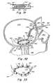
- FIG. 4is an illustrative diagram showing the use of the catheter of the present invention in connection with mitral valve repair
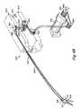
- FIG. 5is schematic diagram of the catheter system of the present invention as deployed through the urethra for a surgical procedure in the bladder;
- FIG. 6is a perspective view of one embodiment of a system embodying the catheter apparatus of the present invention.
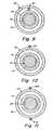
- FIG. 7is a more detailed perspective view of the catheter apparatus
- FIG. 8is an enlarged view of a portion of the catheter apparatus particularly at the distal end section thereof;
- FIG. 9is a cross-sectional view through the catheter apparatus as taken along line 9 - 9 of FIG. 7 ;
- FIG. 10is a cross-sectional view through the catheter apparatus as the distal end section thereof, as taken along line 10 - 10 of FIG. 7 ;
- FIG. 11is a cross-sectional view similar to that illustrated in FIG. 9 for an alternate embodiment of the invention depicting dual-direction flexing;
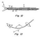
- FIG. 12is one design of tool construction in accordance with the present invention employing inner and outer catheters and inner and outer cables;
- FIG. 13is a schematic diagram of the tool or mini-tool showing certain parameters relating to position control
- FIG. 14is a block diagram of the controller used with the telerobotic system of this invention.
- FIG. 15is a block diagram of further details of the controller particularly details of the module board
- FIG. 16is a block diagram of the control algorithm in accordance with the present invention.
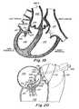
- FIG. 17is a schematic diagram illustrating one mechanism for providing mitral valve repair employing a ring mechanism
- FIG. 18illustrates schematically the concept of the present invention in connection with mitral valve repair
- FIG. 19is a diagram of a heart muscle illustrating the position of the mitral valve
- FIG. 20illustrates further detail of the mitral valve construction as well as the catheter and tool used in the procedure
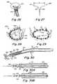
- FIG. 21is a more detailed cross-sectional drawing of the portion of the mechanical member, particularly the means for tightening the retaining means;
- FIG. 22shows further details of the structure of FIG. 21 ;
- FIG. 23is a schematic illustration of a section of the mitral valve ring showing the fiber and the securing of one end of the fiber;
- FIG. 24illustrates somewhat further detail of a means for retaining the catheter in position
- FIG. 25is a diagram illustrating alternate means for holding the catheter in place
- FIG. 26illustrates a view of a mitral valve
- FIG. 27is a schematic diagram of the mitral valve indicating the ring area and leaflets
- FIG. 28is a schematic illustration showing the mitral valve construction and a mechanical member for retaining and tightening
- FIG. 29is schematic diagram of another technique for mitral valve repair employing a wire to be tightened like a lasso;
- FIG. 30is a schematic diagram illustrating a catheter and tool construction containing a tether cable and anchor elements within the inner catheter;
- FIG. 30Ashows a cable termination tool for crimping
- FIG. 30Bshows a tool for cutting
- FIG. 31illustrates a staple array of the present invention
- FIG. 32illustrates the mitral valve construction as well as the staple apparatus and technique of the present invention
- FIG. 33is an illustration of the staple array when applied and secured to the valve annulus
- FIG. 34is a schematic illustration of an alternate embodiment for the staple array
- FIGS. 35A and 35Billustrate another version of the invention wherein the guide catheter is robotic
- FIG. 36schematically represents a system of the present invention for repairing a mitral valve
- FIG. 36Ashows a pin for anchoring
- FIG. 37illustrates the anchoring system engaged with the mitral valve
- FIG. 38illustrates another version in accordance with the invention employing a balloon with the balloon in a deflated state
- FIG. 39schematically represents portions of the heart muscle and the positioning of the balloon relative to the mitral valve
- FIG. 40illustrates the balloon in its inflated state positioned at the mitral valve
- FIGS. 41A-41Ddepict still another form of catheter in accordance with the present invention.
- FIG. 42is a perspective view of another embodiment of the present invention.
- FIG. 42Ais an enlarged detail perspective view of the tool
- FIG. 43is an exploded perspective view of, in particular, the interlocking modules of the flexible instrument system of FIG. 42 ;
- FIG. 44is a partially broken away rear elevational view of the interlocking modules as seen along line 44 - 44 of FIG. 42 ;
- FIG. 45is a cross-sectional side view through the interconnecting modules and as taken along line 45 - 45 of FIG. 42 ;
- FIG. 46is a cross-sectional plan view through the instrument module taken along line 46 - 46 of FIG. 45 ;
- FIG. 47is a cross-sectional plan view taken through the base module of the system of FIG. 42 , and as taken along line 47 - 47 of FIG. 45 ;
- FIG. 48is a cross-sectional end view taken along line 48 - 48 of FIG. 47 ;
- FIG. 48Ais a cross-sectional view taken along line 48 A- 48 A of FIG. 48 ;
- FIG. 48Bis a fragmentary plan view of a drive wheel engagement slot by itself as taken along line 48 B- 48 B of FIG. 48A ;
- FIG. 49is a schematic perspective view showing mechanical cabling between the drive unit and the flexible instrument system.
- the present inventionprovides a system for remotely controlling a flexible instrument for use in medical applications, typically for operative or other medical procedures.
- the flexible instrumentcomprises a shaft or a tube of sufficient dimensions for passing through a small incision or natural body lumen or cavity and ultimately, for positioning a distal end of the shaft within the body at an internal target (operative) site.
- the flexible instrumentcan also support a tool at its distal end to allow more intricate medical procedures.
- a user or surgeoncan control the position of the shaft from a master station, allowing operation from another part of the operating room, or even from another room or another building.
- the shaftcan comprise one or more flexible segments, which a user can controllably bend, providing finer control in directing the shaft toward the target site.
- the controlcan result in, for example, a deflection or turning of the shaft, for guiding this shaft through or within various body cavities or lumens.
- the controllable bendingis also useful for more precise positioning of a distal end of the flexible instrument at a desired operative site.
- the flexible instrumentis used to perform minimally invasive procedures.
- “Minimally invasive procedure,”refers herein to a surgical procedure in which a surgeon operates through small cut or incision, the small incision being sufficiently necessary to access the operative site.
- the incision lengthranges from 1 mm to 20 mm in diameter, preferably from 5 mm to 10 mm in diameter. This procedure contrasts those procedures requiring a large cut to access the operative site.
- the flexible instrumentis preferably used for insertion through such small incisions and/or through a natural body lumen or cavity, if necessary, so as to locate the catheter at an internal target site for a particular surgical or medical procedure. Examples of such minimally invasive procedures include intravascular procedures, such as the repair of a cardiac valve.
- the introduction of the flexible instrument into the anatomymay be by percutaneous or surgical access to a lumen or vessel, or by introduction through a natural orifice in the anatomy.
- FIG. 1is a block diagram schematically illustrating the three main components of the remote control system of the present invention.
- a surgeon or usercan input control actuations at master station 1 , typically through an input device (not shown).
- Slave station 3is separate and remote from the master station and controls the motion of the flexible instrument, in accordance with the user input from master station 1 .
- Master station 1 and slave station 3may be in relatively close proximity to each other, such as in the same operating room, or can be displaced from each other by miles.
- Controller 2provides a telecommunications or electronic communications link coupled between the master station and the slave station. Controller 2 typically includes a computer. Controller 2 receives a command from the input device of master station 1 and relays this command to slave station 3 .
- FIG. 6is a schematic of the remote control system of the present invention.
- the systemincludes: (1) A master station comprising a user interface or surgeon's interface 11 ; (2) A slave station comprising a flexible instrument including shaft 30 which supports tool 18 .
- Shaft 30is connected to and is controllable from mechanically drivable mechanism 26 , which in turn is engageably received by receiver 24 , both of which are mechanically driven by drive unit 13 , (alternatively mechanical drive 13 ); and (3) a controller or computation system 12 to translate a user's commands from user interface 11 to drive unit 13 , which then drives the articulations of shaft 30 and tool 18 .
- FIG. 6illustrates a system where a user or surgeon can control shaft 30 and tool 18 by manipulating interface handles 30 A of user interface 11 .
- the movement of handle 30 Acauses responsive movement of tool 18 through the coordinating action of computation system 12 .
- tool 18can be a pair of graspers, scissors, staplers, etc. and manipulation of handle 30 A can cause the jaws of tool 18 to open and close.
- Surgeon's interface 11is in electrical communication with computing system 12 , which is, in turn, in electrical communication with drive unit 13 .
- drive unit 13comprises a plurality of motors.
- the drive unit 13is in mechanical communication with shaft 30 via conduit 23 , which houses a plurality of mechanical cables driven by the plurality of motors in drive unit 13 .
- drive unit 13is solely in mechanical communication with shaft 30 . Because of the mechanical communication with shaft 30 , the electromechanical components in drive unit 13 are disposed in an area remote from the operative site, and preferably in an area outside the sterile field. Preferably, objects that are difficult to sterilize, e.g. motors or electromechanical components, are kept at a sufficient distance from the patient to avoid contamination.
- the sterile fieldhas the rest surface of the operating table as its lower boundary.
- drive unit 13is preferably located below the plane of the sterile field, i.e. below the rest surface of the operating table.
- the patient or subjectmay be further protected from drive unit 13 with a sterile barrier, such as a sterile cloth.
- a sterile barriersuch as a sterile cloth.
- one aspect of the present inventionprovides a drive unit capable of remotely driving articulation of a flexible instrument, where the drive unit is remote from the subject and the flexible instrument.
- the slave station of the present inventionemploys, to a large part, a mechanical arrangement that is effected remotely and includes mechanical cables and flexible conduits coupling to a remote motor drive unit. This provides the advantage that the instrument is purely mechanical and does not need to be contained within a sterile barrier.
- the instrumentmay be autoclaved, gas sterilized or disposed in total or in part.
- drive unit 13mechanically drives the flexible instrument (comprising shaft 30 and tool 18 ) through conduit 23 , receiver 24 and mechanically drivable mechanism 26 (alternatively known as mechanically drivable interface or shaft mount).
- Conduit 23houses a plurality of separate mechanical cables to mechanically connect drive unit 13 with receiver 24 . The mechanical cables physically contact and drive the motions of shaft 30 and tool 18 .
- Conduit 23is engageable and disengageable with drive unit 13 , i.e. attachable and detachable (see discussion of FIG. 49 , below). Although two conduits 23 are depicted here, it is understood that more or fewer conduits may be used, depending on the particular application.
- drive unit 13comprises a plurality of motors, which drive the mechanical cables extending through conduit 23 and terminating at receiver 24 .
- Receiver 24interlockably receives mechanically drivable interface 26 , which engages a separate set of cables extending through shaft 30 and at least one cable line operating tool 18 .
- engaging drivable interface 26 with receiver 24provides a mechanical (physical) connection from drive unit 13 to control certain motions of shaft 30 and tool 18 .
- Receiver 24which is supported by a carriage, is capable of moving along a linear path represented by the arrow 22 via rails 25 .
- Cables in conduit 23also mechanically drives the translation of receiver 24 along rails 25 .
- the rails, and thus the linear translationextend at an acute angle with respect to the operating table, as well as the subject.
- This angular arrangementdisposes the flexible instrument system in a convenient position over the patient. This arrangement also minimizes the number of components that operate within the sterile field, as drive unit 13 is maintained at a location remote from the sterile field.
- FIG. 49shows a schematic perspective view of the cabling pathway for mechanically coupling one of an array of motors of a drive unit with a tool supported on a distal end of a shaft.
- the cabling pathwaycomprising a plurality of mechanical cables extends from the drive unit to the receiver.
- Another separate set of mechanical cablesconnects the mechanically drivable mechanism, situated at a proximal end of the shaft, to the tool and any controlled flexible segments positioned along the shaft.
- Interlocking the receiver with the mechanically drivable mechanismresults in connecting the two separate sets of mechanical cables, thereby extending the cabling pathway from the drive unit to the distal end of the shaft.
- each of the mechanically drivable mechanism and the receivercan be considered as a coupler, which interlocks or couples with each other.
- FIG. 49shows drive motor 675 positioned within a drive unit, such as drive unit 13 of FIG. 6 .
- the first cabling pathwaycomprises a set of cabling, which engages with and extends from drive motor 675 through idler pulley 682 .
- the cablescontinue through idler pulleys 630 and 632 to drive wheel 622 , which resides in receiver 506 (equivalent to receiver 24 of FIG. 6 ).
- a second separate set of cablesextends about the drive wheel 624 , guided by cam 626 and continues through flexible instrument shaft 528 .
- Tool 534links to shaft 528 via joint 601 , which provides a wrist pivot about axis 532 in the direction of arrows J 4 .
- the two separate sets of cablesare interlocked by interlocking drive wheel 622 of receiver 506 with drive wheel 624 of mechanically drivable mechanism 526 (equivalent to drivable mechanism 26 of FIG. 6 ).
- the interlockinginvolves slotting a blade 606 into a corresponding slot within wheel 624 (see further discussion of FIG. 43 below).
- the interlocking mechanismcan comprise a magnetic attachment, where a first series of magnets in the mechanically drivable mechanism interacts with a second series of magnets in the receiver. Each series of magnets can couple with the mechanical cables.
- FIG. 49also shows the output of motor 675 at a coupler pulley 677 , which is adapted to rotate with an output shaft of the motor.
- the rotational arrow 680indicates this rotation.
- FIG. 49only illustrates one cabling pathway. It can be appreciated that several other cabling pathways can be constructed and arranged to control other motions of the shaft and tool through other motors of the drive unit.
- FIG. 2schematically depicts the components of master station 1 .
- Master station 1can include any one or a combination of input devices A-E and a display F.
- Input device Ais a point-and-touch device.
- Input device Bis a computer mouse.
- Input device Cis a pointing device that may employ a pen or stylus.
- Input device Dis a joystick.
- Input device Eis a hand interface, that provides finer control of the shaft, or a tool positioned at the distal end of the shaft.
- input device Efeatures handles that control the motion of the shaft and a tool.
- the master stationfeatures input device 11 comprising handles 30 A.
- Handles 30 Aare held by the surgeon, who can then torque, translate or rotate catheter member 30 and tool 18 by performing the corresponding motions on handles 30 A.
- a rotation of a handle 30 A via rotation of the surgeon's handcan control rotation of, for example, the outer shaft 32 about the co-axis.
- Flexing or bending of flexible section 42can be controlled by the surgeon flexing his hand at the wrist and activating flex cable 52 , as shown in FIG. 8 (see discussion of FIG. 8 , below).
- a surgeoncan manipulate tool 18 by, for example, closing and opening the jaws of handles 30 A to simulate opening and closing of jaws of tool 18 .
- Display Fprovides a direct video image of the site surrounding the distal end of the shaft.
- An endoscope supporting a camerais inserted into the body of a subject, providing the video feed of the operative site.
- the cameracan be mounted on or housed at the distal end of the shaft.
- the cameracan provide a view of the operative site, or may be positioned away from the site to provide additional perspective on the surgical operation.
- Other detection systemsmay be used for providing different images useful in assisting the surgeon in performing the medical procedure.
- various signalsmay be utilized in conjunction with or in alternative to the video image, such as ultrasound (echocardiography, Doppler ultrasound), angiography, electrophysiology, radiology or magnet resonance imaging (MRI).
- ultrasoundechocardiography, Doppler ultrasound
- angiographyangiography
- electrophysiologyCAD
- radiologyradiology
- magnet resonance imagingMRI
- an audio signalcould be used for guiding the shaft.
- FIG. 6illustrates a computer system 12 , which interfaces the surgeon interface 11 and drive unit 13 of the slave station.
- the drive unit 13contains a series of motors that control cables coupled by way of conduit 23 to control certain movements of the catheter apparatus.
- the controller 12depicted in FIG. 6 essentially links the slave station to the surgeon interface.
- the user input deviceelectronically sends commands, which are translated by the controller and sent to drive unit 13 .
- Drive unit 13then mechanically effects the motion of the shaft, particularly the flexible segment and the tool.
- FIGS. 14 and 15are block diagrams of an embodiment of a motor control system that may be employed in a drive unit of the present invention.
- the master station sidethere is at least one position encoder associated with each of the degrees-of-motion or degrees-of-freedom. At least some of these motions are associated with a motor that may be represented by a combination of motor and encoder on a common shaft. Thus, controlling the motor ultimately controls such parameters as a force feedback to the master station.
- the present systemcan comprise a multiaxis, high performance motor control system, which can support anywhere from 8 to 64 axes simultaneously using either eight-bit parallel or pulse width modulated (PWM) signals.
- PWMpulse width modulated
- the motorsthemselves may be direct current, direct current brushless or stepper motors with a programmable digital filter/commutator. Each motor accommodates a standard incremental optical encoder.
- Host computer 700is connected by digital bus 702 to interface board 704 .
- Host computer 700can be, for example, an Intel microprocessor based personal computer (PC) at a control station preferably running a Windows NT program communicating with the interface board 704 by way of a high-speed PCI bus 702 (5.0 KHz for eight channels to 700 Hz for 64 channels)
- the PCcommunicates with a multi-channel controller electronic card, providing up to 28 axes of motion control, each with a 1.5 kHz sampling rate.
- the controlleris efficient, scalable and robust.
- Interface board 704can be a conventional interface board for coupling signals between digital bus 702 and individual module boards 706 .
- Each module board 706includes four motion control circuits 710 , as illustrated in FIG. 15 .
- Each circuit 710can be, for example, a Hewlett-Packard motion control integrated circuit, such as an IC identified as HCTLL1100.
- FIG. 15depicts a further sub unit of this system, particularly a power amplifier sub unit 712 .
- Power amplifier sub unit 712is based on National Semiconductor's H-bridge power amplifier integrated circuits for providing PWM motor command signals.
- Power amplifier 712is associated with each of the blocks 710 , which couples to a motor X.
- Associated with motor Xis encoder Y. Although the connections are not specifically set forth, it is understood that signals intercouple between block 710 and interface 704 as well as via bus 702 to host computer 700 .
- the motor control systemmay be implemented in two ways.
- the usermay utilize the four types of control modes provided by the motor control sub unit 706 : positional control; proportional velocity control; trapezoidal profile control; and integral velocity control.
- positional controlpositional control
- proportional velocity controlproportional velocity control
- trapezoidal profile controltrapezoidal profile control
- integral velocity controlThe use of any one of these modes can involve simply specifying desired positions or velocities for each motor, and necessary control actions are computed by motion control IC 710 of the motor control sub unit, thereby greatly reducing the complexity of the control system software.
- the usermay choose the second method in which the servo motor control software is implemented at the PC control station.
- Appropriate voltage signal outputs for each motorare computed by the PC control station and sent to the motor control/power amplifier unit ( 706 , 712 ). Even if the computation load is mostly placed on the PC control station's CPU, the use of high performance computers as well as high speed PCI bus for data transfer can overcome this problem.
- FIG. 16describes the overview of the control algorithm for the present invention, mapping out motions of the catheter to that of the surgeon's interface handle in three-dimensional space. Such precise mapping can create the feel of the tool being an extension of the surgeon's own hands.
- the control algorithmcan assume that both the surgeon's interface as well as the catheter always starts at a predefined position and orientation, and once the system is started, it repeats a series of steps at every sampling.
- the predetermined positions and orientationsrelate to the initial positioning at the master station.
- the joint sensors (box 435 ), which are optical encoders in the present embodiment, of the surgeon's interface systemare read, and via forward kinematics (box 410 ) computation of the interface system, the current positions (see line 429 ) and orientations (see line 427 ) of the interface handle can be performed.
- the translational motion of the surgeon's hand motionis scaled (box 425 ) whereas the orientations are kept identical, resulting in desired positions (see line 432 ) and orientations (see line 434 ) of the catheter's tool.
- the resultsare then inputted into the inverse kinematics algorithms for the catheter's tool, and finally the necessary joint angles and insertion length of the catheter system are determined.
- the motor controller (box 420 )then commands the corresponding motors to positions such that the desired joint angles and insertion length are achieved.
- FIG. 16provides an initial start position for the handle, indicated at box 440 .
- the output of box 440couples to a summation device 430 .
- the output of device 430couples to scale box 425 .
- Initial handle position 440is established by first positioning the handles at the master station so as to establish an initial master station handle orientation in three dimensional space. Initial handle position 440 is then compared to the current handle position at device 430 . The output from device 430 is then scaled by box 425 to provide the desired tool position on line 432 coupled to the catheter inverse kinematics box 415 .
- the slave stationcomprises a flexible instrument, e.g. a shaft optionally supporting a tool at its distal end, for insertion into a subject.
- the flexible instrumentis a catheter.
- Catheteras defined herein refers to a shaft adapted for, but not necessarily limited to, insertion into a subject, and more particularly for insertion into natural body lumens, canals, vessels, passageways, cavities or orifices.
- the shaftis typically tubular, but any elongate shaft may be adaptable for insertion into the subject.
- the shaftcan be solid or hollow.
- a subjectcan be a human, an animal, or even individual organs or tissues that are dead or living.
- the introduction of the flexible instrument into the human or animal bodymay be by percutaneous or surgical access to a lumen or vessel, or by introduction through a natural orifice in the body.
- natural lumensinclude body vessels such as a blood vessel (artery, chamber of the heart or vein), urinary system vessels (renal collection ducts, calix, ureter, bladder or urethra), hepatobilliary vessels (hepatic and pancreatic ducts, chyle ducts; common or cystic duct), gastrointestinal tract (esophagus, stomach, small and large intestine, cecum and rectum), gynecological tract (cervix, uterus, fallopian tube or milk ducts and mammary canals of breast), nasopharynx (eustacean tube, sinuses, pharynx, larynx, trachea, bronchus, bronchiole, tear duct) seminal vesicle, spinal
- the shaftcan be constructed from a standard 9 French (2.67 mm diameter) coronary guiding catheter.
- the shaftmay support various forms of tools, typically at its distal end.
- a usercan manipulate tool 18 along a single axis of motion where tool 18 is, for example, a grasper, scissors or general mechanism (such as a stapler or clip applier).
- tool 18is, for example, a grasper, scissors or general mechanism (such as a stapler or clip applier).
- tool 18is, for example, a grasper, scissors or general mechanism (such as a stapler or clip applier).
- toolsmay be located at a position other than the distal end of the shaft.
- the toolsaid in carrying out various surgical or medical procedures, including, but not limited to: 1. Grasp; 2. Cut/lyse/puncture; 3. fill/drain; 4. Secure (suture, staple, anchor); 5. Implant, i.e., any procedure that leaves an object in the body after withdrawal of the flexible instrument; 6. Remove; 7.
- Exemplary objects implanted in a subjectinclude staples, tacks, anchors, screws, stents, sutures, and a variety of other objects implanted by physicians and medical professionals.
- the procedure of deliveringcan further include delivery of agents including, but not limited to: 1. Adhesives. 2. Cryonics. 3. Drugs. 4. Biologic agents. 5. Radioactive elements. 6. Bulking agents.
- the flexible instrumentcan be used as a sensor.
- Parameters that may be sensedinclude, but are not limited to: 1. Force. 2. Pressure. 3. Electrophysiological signals. 4. Chemical, oxygen, Ph, blood gas. 5. Temperature. 6. Vibration.
- the slave stationalso comprises a drive unit capable of articulating the flexible instrument, particularly the shaft and the tool.
- the drive unitis to drivably coupled to a receiver for receiving the mechanically drivable mechanism. In one embodiment, this coupling occurs via cables.
- the drive unitis electronically controllable from the master station, as there is an electronic link between the drive unit and a user input device of the master station.
- the drive unitWhen the receiver receives the mechanically drivable mechanism, the drive unit then has a direct pathway for controlling operation of the shaft and tool. If the shaft has a controlled flexible segment, the drive unit is capable of activating or bending the flexible segment via the mechanically drivable mechanism, for actuation of the shaft, the tool and positioning of the tool at an operative site within the subject. In one embodiment, drive unit is capable of bending the flexible segment via a first set of cables which couple the drive unit to the receiver, and a second set of cables which drivably couple the mechanically drivable mechanism to the flexible segment and the tool.
- One aspect of the present inventionprovides a remote controlled outer (guide) catheter having a distal end disposed at or in an area about an operative site, preferably in the immediate area of an operative site.
- a coaxial inner (working) catheter nested within the outer cathetercan then be used to perform the surgical or medical procedure.
- Previous surgical proceduresinvolve insertion of a trocar or cannula into the subject at a relatively short depth to provide an opening for receipt of the catheter, which is then guided to the operative site.
- the catheteris not disposed at the immediate area around the operative or target site. Thus, if the surgeon needs a second catheter, the first catheter must be withdrawn and the second catheter is guided to the target site. Such repeated insertions can aggravate trauma experienced by the patient.
- the feature of the present inventionemploys an outer catheter disposed at the target site, which allows more than one shaft to be inserted and withdrawn with minimal irritation or trauma experienced at the passageway leading to the operative site.
- the outer catheter housing a coaxial inner catheteris disposed at the target site.
- the inner cathetercan immediately function at the operative site. If a second inner catheter is required, the first inner catheter can be quickly withdrawn through the outer guide catheter and the second inner catheter inserted through the outer catheter with minimal injury to the subject.
- FIG. 3depicts a system of remote controlled coaxial catheters. This system employs three coaxial or nested catheters L 1 -L 3 . Dashed line I represents an incision or entry point of the patient.
- FIG. 3also illustrates computer controls C 1 -C 3 , which are outside of and remote from the patient. “Remote from the patient” refers herein to any location outside the sterile field.
- Computer controls C 1 -C 3are associated with corresponding actuators A 1 , A 2 and A 3 , (i.e. drive units) which in turn are associated with shafts L 1 -L 3 , respectively.
- actuators A 1 , A 2 and A 3i.e. drive units
- the controller C 1controls an actuator A 1 which, in turn, controls a certain action or movement of the outer shaft L 1 .
- actuator A 1which, in turn, controls a certain action or movement of the outer shaft L 1 .
- shafts L 1 -L 3can be independently controlled by one actuator, which independently drives specific cables leading to each of shafts L 1 -L 3 .
- the present inventionallows shafts L 1 -L 3 to be remote controlled independently from each other. For example, shaft L 1 can remain stationary while shaft L 2 undergoes linear translations or rotations about the co-axis.
- the distal end of shaft L 3can also carry out these motions as well as a bend or flex independent of shafts L 1 or L 2 .
- Shaft L 2can be controlled to, for example, provide a rotational movement so as to enable rotation of a distal tool.
- the control of a tool supported at a distal end of a shaftis independent of the motions of shafts L 1 -L 3 .
- all shafts L 1 -L 3can undergo a simultaneous bend or deflection at a single operative segment or flexible segment, labeled as O in FIG. 3 .
- FIG. 7illustrates the outer and inner shafts.
- shaft 30comprises an outer shaft 32 housing and coaxial with inner shaft 34 .
- Outer shaft 32 and inner shaft 34extend from and within mechanically drivable interface 26 .
- Interface 26mechanically couples a drive unit (shown in FIG. 6 ) with shaft 30 .
- Interface 26further comprises a series of control elements, such as pulleys 64 and 72 , which run cable lines 52 and 28 , and gears 60 and 68 for controlling rotation of the shafts.
- outer shaft 32 and inner shaft 34 about the co-axiscan be controlled independently.
- Control element 60 , or gear 60 in interface 26encircles outer shaft 30 and controls the rotational position of guide shaft 32 in the direction indicated by rotational arrow 65 .
- Gear 68 in interface 26encircles inner shaft 34 .
- Control element 68controls the rotational position of the inner shaft 34 in the direction indicated by rotational arrow 69 .
- Rotational arrows 65 and 69indicate rotation about the “shaft lumen axis”, i.e. the axis tangential to the cross section of the shaft lumen.
- control element 68would control the rotational position of the tool about the shaft lumen axis as well. If the distal end were flexed, the shaft would curve and rotation of the shaft would cause the tool to trace a circle, and not cause the tool to rotate about its internal axis. As described below, another control can be positioned in the mechanically drivable interface for solely controlling the tool independent of the shaft controls.
- a flexible instrumentcomprises a shaft having at least one section that is flexible.
- “Flexible”refers herein to a material that is inherently and sufficiently deformable to readily pass atraumatically through a natural body lumen, cavity, vessel, orifice and the like.
- the shaftis sufficiently flexible to readily flex and/or conform to a pathway in an anatomic vessel, lumen, cavity or the like.
- Non-flexible or rigid catheterscan be distinguished from flexible instruments by the following test. By knowing the dimensions of a rigid catheter and the point of entry into the subject, one can calculate the position of the catheter end point inside the subject. In contrast, even if the dimensions and point of entry of a flexible shaft were known, the position of its end point within the subject cannot be calculated with precision because the flexible shaft may bend.
- Flexible instruments of the present inventioncan also be distinguished from other known catheters that mimic bending motions solely through a series of rigid sections linked by joints.
- a “bend”is not the result of a deformation of the catheter material but by the pivoting or rotation of two rigid sections about a joint.
- flexible instruments of the present inventioninclude at least one flexible segment that is bendable without requiring the use of joints. The bending is remotely controlled, allowing deflection at these flexible segments away from the lumen axis of the segment. Bending in this sense is possible by choice of inherent flexibility of the instrument coupled with an induced deflection at the flexible segment. Inherent flexibility can be achieved by choice of a deformable material, such as.
- Inherent flexibilitycan also be achieved by designed construction using a more rigid material, for example carving out segments of the material, i.e. slotting the material, such that the material is sufficiently thin for bending.
- the flexible instrumentcan comprise rotatable or pivotable joints, but the flexible capability is not the result of employing such joints, but by the deformability of the shaft material.
- the bendingis remotely controlled via a drive unit drivably coupled to the receiver for receiving a mechanically drivable mechanism or shaft mount. The shaft mount is then drivably coupled to the controlled flexible segment, thereby providing a drivable bending mechanism.
- the shaftcan be tailored for a particular body lumen. Factors of the shaft construction include resiliency of the walls of the lumen, curvature of the passageway, location of the target site, diameter of the lumen, etc.
- a shaft for passing through a coloncan be, but is not necessarily, manufactured from a material that is less deformable than a shaft for passing through a small, delicate blood vessel. Lumens that present passageways of high curvature may also require a more easily deformable, and thus more flexible, shaft than does a relatively straight lumen. Deformability of the shaft can also be tailored by varying the dimensions, particularly the diameter, of the shaft.
- a usercan controllably bend or flex at least a section of the flexible instrument.
- this controlled bendcan be provided by a shaft having at least one flexible segment, alternatively a controlled flexible segment.
- a usercan induce a bend in the shaft at the flexible segment.
- the bend at the flexible segmentis actuated mechanically, thus distinguishing this aspect of the present invention from prior art catheters where the bends are induced electrically.
- U.S. Pat. No. 5,238,005describes a bending mechanism caused by varying the electrical resistance through a catheter material having a negative coefficient. Heating one area of a catheter by increasing its electrical resistance results in contraction of that area, causing the catheter to deflect toward the contracted area. In contrast, the present catheter responds to mechanical forces.
- FIGS. 7 and 8illustrate one embodiment of a controlled flexible segment.
- FIG. 7shows controlled flexible segment 42 residing between proximal end 36 and distal end 38 of shaft 30 . It is understood, however, that flexible segment 42 can be positioned on any portion of shaft 30 .
- FIG. 8provides an expanded view of flexible segment 42 and illustrates one construction of flexible segment 42 .
- flexible segment 42is constructed by providing inner shaft 34 as a flexible material nested within outer shaft 32 . Outer shaft 34 is split into rigid proximal and distal sections 36 and 38 , both encircling inner shaft 34 .
- flexible segment 42is the gap between proximal and distal sections 36 and 38 .
- Shrink-wrap pieces 44 and 45extend over the respective facing ends of the proximal and distal shaft sections 36 and 38 and adhere these facing ends to the flexible inner shaft.
- flexible segment 42may be in the form of a metal coil of diameter similar to the diameter of outer shaft sections 36 and 38 .
- FIG. 8illustrates outer shaft 32 as being rigid, it can be appreciated that outer shaft 32 can be constructed of a flexible material as well, although its flexibility is preferably less than that of inner shaft 34 .
- the bending of flexible segment 42is controlled through flex wire 52 extending from mechanically drivable mechanism 26 and through flexible segment 42 , terminating at point 54 of distal end 38 (see FIG. 8 ).
- Flex wire 52is preferably disposed between inner shaft 34 and outer shaft 32 .
- FIG. 8shows termination point 54 residing on the outer surface of distal end 38 , although conceivably other surfaces of distal end 38 can serve as termination points.
- the other end wire 52resides within drivable mechanism 26 on control pulley 64 .
- Turning pulley 64has the effect of pulling wire 52 in a direction parallel to shaft 30 pointing towards drivable mechanism 26 . Because wire 52 is terminated at 54 , this pull causes the distal shaft section 38 to deflect in a direction indicated by the arrow 55 , as shown in FIG. 7 .
- FIG. 11illustrates an embodiment where two cables actuate bending the bending.
- FIG. 11is a cross-sectional view of outer shaft 32 receiving inner shaft 34 at termination point 52 .
- Two cables 52 A and 52 Bterminate on outer 32 on opposite sides of distal shaft section 38 . Cables 52 A and 52 B may be manipulated so as to deflect the distal shaft section in opposite directions, in a manner described previously.
- Those of ordinary skill in the artcan readily appreciate that employing multiple cables results in a shaft capable of deflecting in any number of directions.
- FIG. 12depicts a distal end of shaft 30 , showing operative segment O (e.g. flexible segment 42 ) and tool 18 .
- FIG. 12shows two coaxial catheters including an outer shaft O 1 (such as outer shaft 32 ) and inner shaft O 2 (such as inner shaft 34 ).
- outer cable O 3provides translational and rotary motion.
- Outer cable O 3which is disposed between outer and inner shafts O 1 and O 2 , provides the lateral rotation (or yaw motion) of tool 18 .
- Inner shaft O 2rotates tool 18 and inner cable O 4 actuates the jaws of tool 18 .
- the tool of FIG. 12provides a single degree-of-freedom in order to actuate a gripper, scissors or generic mechanism (such as a stapler or clip applier).
- An examplemay be a bi-directional gripper 5 mm in length and 2.67 in diameter.
- the system comprising the flexible instrumentcomprises tool or mini-tool ( 18 ), the operative segment ( 42 ), the catheter stem ( 32 , 34 ), the coupler ( 24 , 26 ) comprising the mechanically drivable mechanism 26 and the receiver 24 , the drive unit ( 13 ), the controller ( 12 ) and the surgeon's interface ( 11 ).
- the couplerprovides a translational degree-of-freedom achieved by using a sliding mechanism, i.e. rails 25 , onto which the coupler is mounted, as illustrated in FIG. 6 .
- the operative or controlled flexible segmentprovides a number of articulations in order to position and orient tool 18 .
- the catheter ( 30 )has four (4) degrees-of-freedom, i.e.
- a fifth degree-of-freedommay be provided by the actuation of the mini-tool, as tool 18 can provide at least a single axis of motion for a grasper, scissors or general mechanism (such as a stapler or clip applier).
- the combination of one translation and two rotationsallows the operative segment to arbitrarily position the mini-tool in three dimensional space.
- a final degree-of-freedomrotates the mini-tool axially.
- FIG. 13schematically illustrates the various degrees of freedom by which the catheter can be manipulated, particularly the axial and lateral rotations, or the translation motion allowing independent control of the tool position within the surgical space, as well as axial rotation of the tool.
- the system of FIG. 6provides a physician with seven independent command inputs, including position orientation ( ⁇ j , ⁇ j , ⁇ j ) and tool grip angle ⁇ j .
- FIG. 42is a perspective view of another embodiment of the slave station for a remote controlled flexible instrument.
- FIG. 42depicts flexible instrument system 500 supported from support bracket 502 , which extend to the operating table (see FIG. 6 ).
- the support bracketis supported from the side of the operating table and may be adjustable in position relative to the operating table, to dispose system 500 in a convenient position over the patient.
- bracket 502is secured to the operating table at one end. The other end of bracket 502 supports the entire flexible instrument by means of a two-piece structure similar to that described in copending U.S. Provisional Applications Ser. No. 60/279,087 filed Mar. 27, 2001.
- a knobmay be provided on support base 504 , not shown in FIG. 42 .
- system 500can be positioned at an acute angle with respect to the operating table.
- Flexible instrument system 500comprises flexible instrument 510 having a shaft 528 extending to mechanically drivable mechanism 526 , which interlocks with base (or receiver) 506 .
- Base 506is supported on carriage 508 .
- Carriage 508in turn is adapted for linear translation and supported by elongated rails 512 and 514 .
- Rails 512 and 514terminate at one end via end piece 516 , which provides further support.
- Support base 504terminates rails 512 and 514 at their other end.
- Carriage 508includes bearings or bushings 509 that support the carriage from rails 512 and 514 .
- Flexible instrument system 500employs two separate cable bundles for mechanically driving the flexible instrument along rails 512 and 514 .
- Pulley 521(dotted outline), residing within carriage control module 520 , receives a first pair of cables 518 .
- Pulley 521also receives a second set of cable (see cabling sections 513 and 515 of corresponding FIG. 43 ), which runs through carriage 508 to a further pulley 522 supported by end piece 516 .
- the second set of cablescontrols the translational motion of carriage 508 and terminates at point 519 (see FIG. 45 ).
- FIG. 42also shows a set of cables 524 for driving control elements, e.g. pulleys within receiver 506 . These control elements move the shaft and the tool in several degrees-of-freedom.
- Arrow J 1indicates the linear translation via module 520 .
- Rotational arrow J 2indicates rotation of flexible shaft 528 of flexible instrument 510 about the inner axis parallel with the shaft length.
- Arrow J 3represents the flexing or bending of flexible shaft 528 at controlled flexible segment 530 .
- flexible segment 530is positioned directly adjacent tool 534 at the distal end of shaft 528 .
- Arrow J 4represents the pivot action of a wrist joint, which links tool 534 to shaft 528 , about axis 532 .
- tool 534is exemplified as a grasper, and arrows J 5 and J 6 represent the opening and closing actions of the tool jaws. Motions indicated by arrows J 2 -J 6 are controlled from cabling 524 originating at receiver 506 .
- FIG. 42Aprovides an enlarged perspective view of the distal end of shaft 528 including flexible segment 530 and tool 534 .
- Tool 534comprises upper grip or jaw 602 and lower grip or jaw 603 , both supported from link 601 .
- Base 600is affixed to or integral with flexible shaft 528 .
- Link 601is rotatably connected to base 600 about axis 532 .
- a pivot pinmay be provided for this connection.
- Upper and lower jaws 602 and 603are rotatably connected to link 601 about axis 536 and again, a pivot pin can provide this connection.
- FIG. 42Ashows eight cables at 538 extending through the hollow inside of shaft 528 for control of tool 534 and flexible segment 530 .
- Two of these cablesoperate the bend of flexible segment 530
- two cablesoperate one of the jaws 602
- two cablesoperate the other of the jaws 603
- the last two cablesoperate the wrist action about the axis 532 . All of these cables travel through the hollow shaft 528 and through appropriate holes in flexible segment 530 , e.g. wire 525 , as well as holes in base 600 .
- Each of these pairs of cablesoperates in concert to open and close jaws, pivot about the wrist, and bend flexible segment 530 .
- One pair of cablestravels through shaft 528 and through appropriate holes in the base 600 , wrapping around a curved surface of the link 601 and then attaching to the link. Tension on this pair of cables rotates the link 601 along with the upper and lower grips or jaws 602 and 603 about axis 532 .
- Two other pairs of cablesalso extend through the shaft 528 and through holes in the base and then pass between fixed posts 612 . These posts constrain the cables to pass substantially through axis 532 , which defines rotation of link 601 .
- This constructionessentially allows free rotation of link 601 with minimal length changes in the cables passing to jaws 602 and 603 .
- the cables actuating jaws 602 and 603are essentially decoupled from the motion of link 601 and are not effected by any rotation of link 601 .
- Cables controlling jaw movementterminate on jaws 602 and 603 . These cables permit independent operation of the jaws 602 and 603 in respective clockwise and counter clockwise directions with respect to axis 536 .
- Each of the jaws 602 and 603 , as well as the link 601may be constructed of metal.
- link 601may be constructed of a hard plastic material.
- Base 600may also be constructed of a plastic material and may be integral with shaft 528 .
- Flexible segment 530Bending of flexible segment 530 is provided via diametrically disposed slots 662 , which define spaced ribs 664 .
- Flexible segment 530also has a longitudinally extending wall 665 through which cabling may extend, particularly for the operation of the tool.
- One of the pairs of cables of bundle 538 controlling flexible segment 530terminates where base 600 intercouples with shaft 528 . This pair of cables works in concert to cause bending as indicated by arrow J 3 , i.e. in a direction orthogonal to the pivoting provided at wrist axis 532 . In FIG. 42A only one cable 525 of two is illustrated.
- FIG. 43is an exploded prospective view showing carriage 508 , receiver 506 and drivable mechanism 526 .
- Carriage 508is adapted for motion along rails 512 and 514 .
- Pulleys 521 and 522receive cabling, i.e. cable sections 513 and 515 , which terminate at the carriage base at point 519 .
- Other sections of this cableextend through an elongated hole or passage within carriage 508 .
- Receiver 506 and drivable mechanism 526each comprise enclosed housings supporting a plurality of control elements, such as intercouplable drivewheels and associated pulleys or cams.
- Inter-engaging gears 540 and 542are supported respectively in the modules 506 and 526 .
- a pair of cables from bundle 524engages pulley 544 (see FIG. 45 ) which, in turn, drives gear 540 , and which further, in turn, drives gear 542 for providing rotation of shaft 528 .
- Collar 546is provided at the terminus of the proximal end of shaft 528 for supporting shaft 528 , which is driven by gear 542 .
- Cabling extending through collar 546 and shaft 528couple mechanical actions from drivable mechanism 526 through the flexible instrument shaft 528 to the distal end thereof.
- Drivable mechanism 526interlocks with receiver 506 , providing the mechanical connection that allows the drive unit to run cabling in flexible instrument 510 .
- Blades 606jutting out from the housing of receiver 506 , engage with corresponding slots 608 associated with drivable mechanism 526 .
- Projecting from the proximal end of receiver 506is ridge 610 , which is substantially U-shaped and provides another interlocking feature for mating with a similarly shaped slot 614 at the same end of drivable mechanism 526 .
- Posts 616 protruding from the housing of receiver 506are adapted to releasably mate with holes 618 in drivable mechanism 526 .
- Posts 616 and holes 618to interlock with each other, but may be released from each other via side-disposed buttons 620 , as illustrated in FIG. 46 .
- FIG. 43also shows the cam locking screws 615 .
- FIG. 44is a partial broken away rear elevational view of interlocking interfaces as seen along line 44 - 44 of FIG. 42 .
- FIG. 44shows alignment posts 616 each having a groove 617 , which is engaged by the corresponding button 620 .
- Button 620is in the form of a plate member biased to a locked position by means of spring 621 .
- a plate for button 620has a keyhole slot for receiving and holding post 616 therein. Button 620 , however, may be manually depressed to release posts 616 and enable ready detachment of drivable mechanism 526 from receiver 506 .
- a retaining pin 625may also be used to limit the travel of the button between in and out positions.
- FIG. 45is cross-sectional side view through the interconnecting modules taken along line 45 - 45 of FIG. 42 .
- FIG. 45shows details of drive wheels (or pulleys) in the modules 506 and 526 .
- Four drive wheels 622are supported within the housing of receiver 506 .
- Drive wheels 622receive cabling for controlling the motions of the shaft and the tool, where the cable protrudes from cable bundle 524 in FIG. 43 .
- Each of these pairs of cablesis controlled from a corresponding motor, which is part of the drive unit (see discussion of FIG. 49 , below).
- FIG. 45also shows output blades 606 , previously shown in FIG. 43 , which extend into corresponding slots 608 . These slots are disposed in respective intergaging drive wheels 624 of the drivable mechanism 526 . Blades 606 have a rectangular end construction for engaging with similar rectangular slots 608 associated with the module 526 . FIG. 45 also shows the gears 540 and 542 in engagement to allow drive to occur from bundle 524 .
- FIGS. 45 and 46show a series of idler cams 626 , one associated with each of drive wheels 624 .
- FIG. 46is a plan cross-sectional plan view through receiver 506 as taken along line 46 - 46 of FIG. 45 .
- FIG. 46shows the placement of cams 626 .
- a cablewraps around each of drive wheels 624 and is held in position by its associated cam 626 .
- FIG. 46also shows all of the cables running parallel to each other at region 627 , where the cables run from respective drive wheels 624 , through collar 546 and extending down inside shaft 528 to the distal end. With the use of the placement and adjustment of cam 626 , the cables are all directed in a manner to easily couple into shaft 528 .
- cams 626has an off-center axis 631 . As viewed in FIG. 46 , cam 626 may be rotated clockwise to tighten its associated cable. Rotation counterclockwise loosens the tension. Cam locking screws 615 secure cam 626 in an adjusted-to position (see FIG. 48 , a cross-sectional view taken along line 48 - 48 of FIG. 47 ). FIG. 48A is a cross-sectional view taken along line 48 A- 48 A of FIG. 48 . As depicted in FIGS. 46 and 48A , the cable associated with each wheel 624 may be secured in a cable clamping hole 633 via a cable clamping screw 635 . A similar clamping arrangement is associated with wheels 622 . A roll pin fixes each wheel 622 to each spindle 607 .
- FIG. 47is a cross sectional plan view taken through receiver 506 , as taken along line 4747 of FIG. 45 .
- the cross-sectional view of FIG. 47illustrates drive wheels 622 associated with receiver 506 .
- Drive wheels 622receive cabling from cable bundle 524 .
- Each of a pair of idler pulleys 630are associated with drive wheels 622 .
- idler pulleys 632are used for directing the cable to idler pulleys 630 and from there to drive wheels 622 .
- FIG. 48Bis a fragmentary plan view of a drive wheel engagement slot by itself as seen along line 48 B- 48 B of FIG. 48A .
- the cross-sectional views of FIGS. 48A and 48Billustrate drive wheels 622 within receiver 506 having associated end blades 606 .
- End blade 606is a screwdriver-type blade that engages a slot previously identified as slot 608 in FIG. 43 .
- This slot 608is in drive wheel 624 of receiver 526 .
- slot 608displays a tapered portion. The tapered portion allows easy registration of end blade 606 and slot 608 , and thus easy registration between drive wheel 622 and drive wheel 624 .
- the bending or deflection of the shaftcan be actuated by mechanical means such as a wire extending along a length of the shaft.
- mechanical meanssuch as a wire extending along a length of the shaft.
- actions at the distal end of shaftsmay be controlled by mechanical elements, such as cables, wires or other tendons.
- FIG. 41Aillustrates shaft 850 having a central lumen. Residing in the central lumen is an operative or controlled flexible segment O, in the form of a plurality of spaced electromagnetic rings 852 , separately labeled as R 1 , R 2 , R 3 and R 4 . Each of rings R 1 -R 4 is associated with wires 854 , similarly labeled as wires W 1 , W 2 , W 3 and W 4 . Rings 852 , once energized, provide bending of shaft 850 at flexible segment O.
- FIGS. 41A and 41Dare meant to be schematic, while FIGS.
- FIG. 41B and 41Care actual implementations for actuation of the rings by means of coils or windings 853 .
- each ringmay be electrically energized via a winding 853 associated therewith.
- FIG. 41Bshows a fully wound winding
- FIG. 41Cshows a half wound winding.
- Ring 852may also have two separate half wound coils on opposite sides thereof.
- Wires 854(in pairs) are selectively energized to energize windings 853 on the rings, which in turn, provide either attraction or repulsion of the rings.
- FIG. 41Dillustrates the results of regions of rings 852 being energized to attract or repel adjacent rings. For example, a certain direction of current flow through windings 853 can create an attraction of the coils at the bottom and a repulsion of coils at the top. This cooperative action causes a bending at the operative or controlled flexible segment O.
- the flexible instrument depicted in FIGS. 6 and 7provides only the distal end as being remotely controlled. It can readily be appreciated that a controlled flexible segment may be provided, not necessarily for action at a target site, but to control certain movements of the catheter to assist in reaching a target site.
- FIGS. 4 and 5illustrate the advantages of a flexible instrument, particularly a catheter having controlled flexibility via controlled flexible or operative segments, for use in performing a procedure or for guiding the instrument through a natural body lumen.
- FIG. 4provides a schematic cross-sectional diagram, illustrating a catheter K for use in mitral valve repair, to be discussed in more detail below.
- FIG. 4also shows catheter K supporting a tool 18 for carrying out certain procedures at the mitral valve annulus, also described in further detail below.
- catheter Kis shown entering the femoral vein V by a percutaneous access at S. From the femoral vein V, catheter K must bend prior to entering the right atrium R.
- Catheter Kthen passes through a septal wall of the heart to the left atrium L, which is directly above the mitral valve M.
- the operative segment of the catheter Kis illustrated at O and is positioned near the very distal end of the catheter K.
- a usercan controllably bend catheter K at the operative segment, to perform a procedure with tool 18 .
- the ability to controllably bend catheter Kprevents tool 18 from conceivably being trapped within femoral vein V, causing damage to the walls of vein V.
- FIG. 5provides a schematic cross-sectional diagram illustrating a surgical procedure where catheter K 1 enters a natural body orifice, such as the urethra for carrying out procedures in, for example, the bladder.
- catheter K 1is shown extending into bladder B 1 .
- the computer controlled segmentidentified as operative or flexible segment O in FIG. 5
- Bladder B 1being an open cavity, does not have lumens leading from the urethra that would naturally guide a catheter towards any particular operative site.
- catheter K 1can bend in any direction and not necessarily in the direction of the operative site.
- the distal end of catheter Kcan be rigid or be “passively” flexible, i.e. made of a flexible material and not necessarily controlled for flexure under remote computer control.
- the catheter Kmay be fed through the femoral vein by direct surgeon manipulation, in which case only the operative segment O is under computer control from a master station.
- the cathetermay translate linearly through the vein under remote master station control, where the catheter can have other operative segments disposed at different locations of catheter K. Each of these operative segments can be controlled from a master station for assistance in the guiding of the catheter to a predetermined target site.
- the cathetermay be inserted manually and also have remote computer control for at least limited linear translation.
- FIGS. 3A-3Cshow different embodiments of flexible instruments with multiple operative or controllable flexible segments.
- Shafts having multiple operative segmentscan be very useful for procedures in a body cavity, as discussed previously, but can also be useful in navigating the shaft through intricate or delicate body lumens.
- FIGS. 3A-3Cschematically illustrate controller CT and a slave portion of the system comprising actuators or drive units A 1 -A 4 and shaft KA, KB or KC having three operative segments O 1 -O 3 .
- a surgeoninputs commands from a master station to cause certain corresponding movements of the shaft at the slave station.
- a surgeon's manipulations at the master stationare coupled to controller CT where these manipulations are mapped to actions at operative segments O 1 -O 3 .
- a surgeonat an appropriate input device, may carry out a first manipulation to control a segment O 1 , a second different manipulation to control the segment O 2 and still a third manipulation to control the segment O 3 , either simultaneously or sequentially.
- a fourth manipulationmay control the tool G.
- FIG. 3Ashows shaft KA having three operative segments, O 1 , O 2 , and O 3 , and tool G at its distal end.
- Actuators A 1 , A 2 and A 3are associated respectively with operative segments O 1 , O 2 and O 3 .
- Actuator A 4controls tool G.
- Each of actuators O 1 -O 3is controlled from controller CT.
- Operative segments O 1 , O 2 and O 3are spaced a certain distance apart from each other, allowing shaft KA to simultaneously experience controlled bends. This arrangement may be necessary for lumens with multiple bends, or for hard to reach operative sites.
- FIG. 3Bshows catheter KB having tool G 1 .
- three operative segments O 1 , O 2 and O 3are spaced from each other along the length of catheter KB. Segments O 1 -O 3 can be controllably bent to form an arc having an imaginary radius point P. Thus, this arrangement of operative segments can actuate particularly acute bends.
- catheter KC in FIG. 3Cemploys three operative segments O 1 -O 3 , which are contiguous. The radius of curvature can be increased.
- non-operative segments of the catheter in FIGS. 3A-3Ccan comprise either a flexible or a rigid material. It can be appreciated that one or more controlled flexible segments can be incorporated in the shaft, depending on the particular application.
- Another aspect of the present inventionprovides a remote controlled flexible instrument operable within the sterile field, and disposable after use.
- the sterility of reusable medical instruments and implementsare maintained by well-known methods such as exposure to sterile solutions and/or autoclaving.
- itcan be more cost effective to manufacture them from low cost materials and dispose them after a single use, or use on a single patient.
- its manufacture from low cost materialsstill results in a costly product due to the intricate nature of the individual parts and the labor required to manufacture complex components.
- the present designallows the use of injection-molded plastic parts.
- the disposable componentcan be easily and quickly engaged into and disengaged from a non-disposable, reusable base.
- the componentscan be locked onto the base by snapping or interlocking matched parts, without having to thread cable wires or attach any intricate components.
- a disposable implementcomprising a disposable mechanically drivable mechanism, a disposable shaft extending from the drivable mechanism, and optionally a disposable tool supported on a distal end of the shaft.
- mechanically drivable mechanism 26comprising gears 60 and 68 and pulleys 64 and 72
- the sides of pulleys 64 and 72feature a first semicircular planar disc stepped up from a second matching semicircular planar disc.
- the sides of the pulleys in receiver base 24correspondingly match the stepped up pattern of pulleys 64 and 72 .
- Engaging drivable mechanism 26 onto receiver 24requires matching and interlocking the respective pulley discs.
- the interlocking featurein effect extends the cabling pathway from the first set of cables running from the drive unit to receiver 24 , to a second separate set of disposable cables contained within drivable mechanism 26 and shaft 30 . No tying or threading of cables is required to engage the disposable portion onto receiver 24 .
- FIG. 42Another design for a disposable implement is illustrated in FIG. 42 .
- the flexible instrument 510comprising drive mechanism 526 and shaft 528 , can be a single piece disposable unit that is readily engageable and disengageable relative to the base module 506 .
- Disposable implement 510may be considered as comprising a disposable, mechanically drivable mechanism such as the coupler or module 526 interconnected to a tool 534 through an elongated disposable flexible shaft or stem 528 .
- This disposable and flexible implementis mounted so that the mechanically drivable mechanism may be connectable to and drivable from a drive mechanism, such as illustrated in FIGS. 6 and 7 .
- the drive mechanismmay be considered as including the coupler or module 506 and the associated drive motors.
- the disposable elongated flexible instrumentis generally inserted into a body vessel or cavity of a subject along a selected length of the disposable elongated instrument with the elongated flexible instrument being disposable together with the disposable mechanically drivable mechanism.
- the disposable implementis purely mechanical and can be constructed relatively inexpensively thus lending itself readily to being disposable. It may be difficult to make only the tool disposable, due to the intricate nature of the tool parts, which may require the user to perform intricate maneuvers and cable threading into the base of the slave station.
- the disposable implementi.e. the tool, shaft and drivable mechanism are manufactured as a single piece disposable unit, thus eliminating the need for intricate instrument or tool exchange procedures.
- the base of the slave stationwhich contacts the disposable implement, is easily cleanable. It is preferred that the disposable implement, which operates within the sterile field, experiences minimal contamination by contacting the slave station.
- the interlocking drivable mechanism 526 and receiver 506features substantially planar surface at the point of contact between the two modules. Regarding receiver 506 , the planar surface is easy to clean and the inner intricate pulleys and cabling are protected from contamination by the housing.
- the housingcan be made of injection-molded plastic that is simple to manufacture and is easily disposable.
- One advantage of the present inventionis the ease of engaging and disengaging the disposable implement.
- a multitude of instrument exchangesmay be required, and the system of the present invention is readily adapted for quick and easy instrument exchange.
- the receiveris maintained in a fixed position, the surgeon can easily exchange instruments by readily decoupling at the modules 506 and 526 .
- the ease of exchanging instrumentslends to the portability of the slave station.
- This portable nature of the slave unitcomes about by virtue of providing a relatively simple flexible instrument in combination with an adaptor (module 506 , module 520 , carriage 508 and associated components) for supporting the flexible instrument. Overall, the slave station is of a relatively small configuration.
- the slave unitis purely mechanical, and is decouplable from the drive unit, the operator can readily position the slave unit. Once in position, the slave unit is then secured to the support, and the mechanical cabling of the slave unit is then attachable to the drive unit. This makes the slave unit both portable and easy to position in place for use.
- FIG. 49shows an embodiment where pulley 677 is readily manually decouplable from motor 675 .
- pulley 677may be a two-piece pulley arrangement comprising a coupler spindle and a coupler disk with the coupler disk secured to the output shaft of the motor. This enables the entire assembly to be disconnected at the motor so that the flexible instrument system 500 with its flexible instrument 510 may be positioned relative to the patient, independent of any coupling with the drive motors. Once the system illustrated in FIG. 42 is in place, then the coupling of the cables can be made at pulley 677 to provide drive to the flexible instrument system.
- Another aspect of the present inventionprovides a system for repairing a cardiac valve, such as a mitral valve.
- Current mitral valve repair techniqueseither open or minimal access, require the surgeon to place the patient on cardiopulmonary bypass and stop the heart. The left atrium is then opened and exsanguinated to allow the surgeon to perform the repair.
- This aspect of the present inventionprovides a minimally invasive mitral valve annuloplasty technique featuring the following advantages: (1) peripheral venous access; (2) the heart can continue to beat during the repair; and (3) assessment of the correction of valve incompetence in real-time using, for example, Doppler ultrasound guidance.
- the present cardiac valve repair systememploys a guide shaft extending from a site outside a patient to an area about the cardiac valve.
- the guide shaftreceives a flexible inner shaft for disposing a tool at the area about the cardiac valve, where the tool is supported at the distal end of the guide shaft.
- the inner shafthas a relatively small diameter enabling percutaneous intravascular and endoscopic surgery.
- the inner shaft, and optionally the guide shaftis capable of accessing the mitral valve from the peripheral circulation, eliminating the need for incisions through the chest wall.
- the inner shaftcan have a diameter ranging from 8 to 15 French (2.5-5.0 mm).
- the outer cathetermay be constructed from a standard 9 French coronary guide catheter, having a diameter of 2.67 mm and a wall thickness of 0.1 mm.
- the inner cathetercan have an outer diameter of 1.1 mm and an inner diameter of 0.09 mm.
- the braided stainless steel cablesare 0.63 mm in diameter and are capable of transmitting 178 Newtons (40 lbs. approx.).
- a feature of this aspect of the present inventionis that the percutaneous access to the mitral valve can be accomplished on a beating heart, eliminating the risks associated with cardiopulmonary bypass (CPB).
- CPBcardiopulmonary bypass
- the procedurecan be performed under physiologic conditions.
- the physicianmay monitor the procedure by, for example, transesophageal echocardiography, instead of a video image.
- This techniqueenables real-time assessment of the correction of the mitral valve regurgitation (MR) during the procedure, further enabling intra-operative provocative cardiac testing, with preload and afterload challenges and cardiac pacing all under trans-esophageal echo and trans-thoracic ultrasound guidance to optimize repair.
- the toolcan be remote controlled, as described herein, and can be designed for use in any procedure of the cardiac valve repair process.
- a first set of toolsis capable of percutaneous mitral valve annuloplasty. This represents a paradigm shift in management of disease from MIS and open surgical to intraluminal interventions. While this catheter-based intervention is described in connection with mitral annuloplasty, the technique can also be applied to other structures such as, by way of example and not limiting, the billiary tree, the genitourinary tract and intraventricular neurosurgery.
- the systemfurther includes a retainer at the area of the cardiac valve, where the retainer is attached to an annulus of the cardiac valve. As will be described in greater detail below, the retainer is closeable via the tool to draw the annulus into a smaller diameter.
- a trans-septal guide catheteris used to guide and support an inner catheter.
- the guide catheteris introduced by percutaneous access, and allows the clinician to access the left atrium via the venous circulation, i.e. through the heart wall (see FIG. 4 ).
- the guide cathetermay be non-robotic, i.e. simply manipulated manually by the surgeon.
- the guide cathetermay be robotically controlled from surgeon manipulations at an input device of the master station.
- the inner catheteris threaded into the left atrium through the guide catheter.
- the inner cathetercontains attachment anchors for deployment at desired points around the mitral valve annulus.
- a remote controlled 5-degree-of-freedom tool and wristcan be utilized to precisely reach the annulus.
- Ultrasoundmay be used to visualize the system and guide the anchor positioning and placement. This ultrasound may be trans-esophageal ultrasound or trans-thoracic ultrasound, for example.
- electrophysiologic signals of the heartmay be used to aid in precisely locating the position of the tool at the fibrous mitral valve annulus.
- FIG. 19is a schematic representation of the heart muscle showing the left ventricle 218 , the right ventricle 219 , the left atrium 220 , the right atrium 221 and the aorta 222 . Between the left atrium and the left ventricle, blood flow is from the left atrium through the mitral valve 210 to the left ventricle 218 .
- FIG. 26illustrates an expanded view of a mitral valve at 210 including annulus 211 and leaflets 213 .
- FIG. 27illustrates schematically the leaflets 213 of the mitral valve 210 with the mitral valve annulus 211 . As a heart muscle ages, it is typical for the annulus of the mitral valve 210 , illustrated in FIG.
- mitral valve repairinvolves, at least in part, shrinking the diameter of the annulus to allow the leaflets to operate properly.
- FIG. 19illustrates an area at the annulus of the mitral valve (that annulus being at the top in FIG. 19 ) identified as trigone area 215 , where the valve ring is more rigid and remains stationary. Because this area is relatively stable and rigid, it is thus difficult to contract, and most of the expansion of diameter of the ring occurs away from the trigone area. This, again, is illustrated in FIG. 20 by the positions shown in solid and in dotted outline.
- FIG. 20shows schematically parts of the heart such as the left atrium 220 and the left ventricle 218 , with the mitral valve 210 disposed therebetween.
- FIG. 20illustrates the annulus of the mitral valve in solid position, at a smaller diameter where the leaflets operate properly.
- the dotted outline 217represents the expanded diameter of the base of the mitral valve, the state at which mitral valve leakage can occur.
- a guide catheter 230is employed, such as a transseptal atrial guide catheter.
- the access for catheter 230is via the vena cava to the right atrium 221 .
- This accessmay be from above via the jugular vein or below by way of the femoral vein.
- a punctureis made in the wall 238 of the right atrium into the left atrium 220 , allowing distal end 232 of catheter 230 to pass into the left atrium 220 .
- FIG. 17illustrates one method of shrinking the diameter of the annulus.
- FIG. 17shows a metal wire ring 100 in place about the mitral valve annulus.
- the ring 100may be initially secured at the trigone area 103 of the mitral valve annulus.
- the technique illustrated in FIG. 17may rely upon a catheter apparatus, such as depicted in FIGS. 6 and 7 herein with an operative segment. At least limited linear translation of the catheter may be accomplished with an apparatus similar to that described in FIG. 6 , although a guide catheter may also be manually inserted at least partially by the surgeon through percutaneous access via the femoral vein.
- the ring 100although depicted in a ring configuration in FIG. 17 , can be first inserted through the catheter in a straightened configuration.
- the metal wire or ring 100is preferably constructed of a material such as Nitinol.
- the characteristics of this materialinclude the ability to retain its form or to be stretched to a straight position. Once the material is passed through the catheter, it can spring back to its ring configuration. The surgeon preferably matches the configuration of the ring, particularly as to its size, to provide a proper fit for the particular mitral valve that is being repaired.
- the straightened wire 100Once the straightened wire 100 has passed through the catheter, it assumes the position shown in FIG. 17 .
- the ringonce in place, is secured to the annulus via wire clips 106 and/or sutures 102 . By drawing on these sutures with the tool, the diameter of the mitral valve annulus is reduced so that it conforms to the size of the wire loop 100 .
- the controlis supplemented by visual considerations such as with the use of ultrasound or electrophysiological feedback.
- FIG. 18provides another embodiment of the present invention employing a catheter system for mitral valve repair.
- FIG. 18provides a schematic representation of a ring 210 of a cardiac valve, such as a mitral valve.
- Fiber 212is looped about or sewn around the annulus (base) of the valve. A number of different types of stitches may be used.
- the fibermay be a thread or a wire.
- the fiberis actually sewn through the annulus of the valve. After the fiber is sewn in this manner, tension is applied to ends 214 of the fiber. The tightening reduces the diameter of the ring, brings the valve leaflets into their proper position so as to avoid valve regurgitation.
- FIG. 20also illustrates a balloon 234 that may be supported at the distal end 232 of the catheter 230 .
- balloon 234is inflated to further support the guide catheter in place with the end 232 extending slightly into left atrium 220 .
- balloon 234is inflated or opened, it can be snugged back against the septal wall 238 between left atrium 220 and right atrium 221 .
- the inner diameter of the catheter 230may be on the order of approximately 5 mm in diameter.
- FIG. 24shows an enlarged view of catheter 230 , with its end 232 and the associated balloon 234 holding catheter 230 in place.
- a malecot 236may be used. This is a mechanical device with expandable wings, as illustrated in FIG. 25 and associated with catheter 230 so as to hold the end 232 of the catheter in place relative to the septal wall 238 .
- FIG. 20also illustrates a flexible catheter 240 with its associated tool 242 extending from the guide catheter 230 .
- Tool 242may be a pair of jaws operable for threading or sewing fiber. These jaws can be controlled externally at a user interface by a surgeon.
- flexible catheter 240reference is made to co-pending provisional application, U.S. Ser. No. 60/269,200, as well as pending application PCT serial number PCT/US00/12553, filed Nov. 16, 2000, both documents of which are hereby incorporated by reference herein.
- FIG. 23reference is also made to the fiber 212 and an end piece 245 that is secured to one end of the fiber 212 .
- Fiber 212is shown sewn through wall 247 .
- FIG. 23also schematically illustrates the tool 242 engaging the fiber 212 .
- flexible catheter 240is threaded through guide catheter 230 to a position just about the mitral valve, as illustrated in FIG. 20 .
- Fiber 212may also, at the same time, be threaded through the catheter member 230 with end piece 245 being accessible for being secured to the valve ring.
- the beginning position of the threading or sewing of the fiber 212is at a position close to or at the trigone area 215 of mitral valve 210 .
- the jaws of tool 242loop stitch the fiber 212 , which may be a small but rigid wire, about the mitral valve in the manner illustrated in FIG. 18 .
- Staples 249may also be employed for holding the wire in place.
- FIGS. 21 and 22illustrate another embodiment to secure an end of fiber 212 .
- the end of fiber 212is pulled so as to close the diameter of the base ring of the mitral valve.
- FIG. 21illustrates guide catheter member 230 at its end 232 , being held in place against the septal wall 238 by balloon 234 .
- Flexible catheter 240 with its tool 242has been withdrawn from catheter member 230 .
- Double-walled structure 250comprises coaxially arranged inner and outer tubes 252 and 254 .
- Fiber 212extends through these tubes and carries therealong a securing piece 256 and a retaining button 258 .
- the inner tube 252is adapted to engage the retaining button 258 and the outer tube 254 is adapted to engage the securing piece 256 .
- FIG. 22shows securing piece 256 and retaining button 258 , along with the fiber 212 .
- the member 250may be withdrawn through the guide catheter 230 .
- the flexible catheter member 240may then be reinserted with a different tool such as a pair of scissors for cutting the exposed end of the fiber 212 .
- FIG. 29shows the cable or wire 120 and schematically illustrates the anchors at 125 .
- the valveis reduced through a “lasso” technique, in which the cable exerts an equal force on all of the anchors.
- This techniqueuses an articulate catheter preferably inserted through a guide catheter, such as illustrated hereinbefore, to place the anchors one at a time into the mitral valve annulus. The cable onto which the anchors are suspended provides the closing force when tensioned by the operator.
- the flexible instrumentcomprises a guide catheter 150 , as illustrated in the diagram of FIG. 30 .
- Inner catheter 155houses an anchor and cable system depicted generally at 160 , including tensioning cable 162 and anchors 164 . Five degrees-of-freedom are provided: (1) rotary, (2) linear, (3) flexure motion with regard to the guide catheter 150 as well as (4) linear and (5) rotary motion with regard to the inner catheter 155 .
- Guide catheter 150may be approximately 8 French in diameter with a computer controlled flexible end portion, illustrated in FIG. 30 as operative segment O.
- a computercontrols three degrees-of-freedom with regard to the guide catheter 150 , along with two degrees-of-freedom of inner catheter 155 . Refer to FIG. 30 and the corresponding motions F 1 -F 5 .
- FIG. 30depicts anchors 164 as having a loop and two legs, although other anchor designs can be readily contemplated.
- the legs of each anchor 164may curl outwards. Once anchors 164 are deployed from the constraint of the inner catheter, they curl outwardly. The curling motion of the anchor legs secures them to the fibrous tissue of the mitral valve annulus.
- the anchorsare fabricated from a super-elastic material such as Nitinol.
- a tensioning cablesuch as the cable or wire 162 illustrated in FIG. 30 may pass through each of the loops of the anchor. This allows an equal force to be placed on each anchor and prevents the anchors from becoming loose in the bloodstream.
- the tensioning cablepasses back through the robot inner catheter and out of the patient. The final tension is adjusted manually by the surgeon (or by computer) to optimize the annular size under direct visualization.
- a deployment wireused to advance and fire the anchors into the annulus wall.
- FIGS. 30A and 30Bdepict a cable termination tool set.
- This setcomprises two catheters used to: (1) crimp the end of the tether cable once the tension is placed on the annulus; and (2) cut off the remaining cable at the end of the procedure. Both of these catheters may use a four-bar linkage or other system.
- FIG. 30Ashows a crimp tool 172 having a pair of jaws 174 that can be used to crimp member 176 about the tether cable 170 .
- the first catheter 172which may be referred to as a cable crimper, holds the crimp element 176 in the jaws 174 with the tether cable 170 pre-threaded through the crimp element and catheter shaft.
- the tensioning of the cablemay be performed under ultrasound guidance.
- one tether cable 170is shown in FIG. 30A , opposite ends of the tether that come from the mitral valve site preferably extend through the crimp element 176 .
- the crimp element 176is actuated by the cable crimper 172 illustrated in FIG. 30A .
- the crimperis actuated by applying tension on the push-pull drive cable 175 and by closing the crimp element at the jaws 174 so that the crimp element crimps the tether cable 170 in the proper position and at the proper tension.
- the cable crimperis removed and the cutting catheter 182 is introduced as also illustrated in FIG. 30B .
- This catheteris also introduced over the tether cable 170 and through the guide catheter. It is advanced up to the crimp, and severs the cable with its jaws 184 by tensioning the push-pull drive cable 185 . The procedure is now completed and the system catheters are then removed.
- the proximal end of the catheteris comprised of a disposable coupling mechanism that engages a drive mechanism, such as is shown in FIGS. 6 and 7 .
- the coupleridentified in FIGS. 6 and 7 as couplers 24 and 26 are adapted for disengagement therebetween.
- One coupler sectionmay be considered as transmitting motion to the guide catheter while the other coupler section may be considered as transmitting motion to the inner catheter and the drive cable. This involves the mechanical coupling of the guide catheter with the coupler so that actions of the guide catheter are controllable from the mechanical control elements of the coupler.
- a drive unitis coupled with the inner shaft and the guide shaft independently, the drive unit capable of independently effecting movement of each shaft to at least one degree of freedom.
- rotary diskstransmit motion from the remotely controlled drive system to the catheter articulations.
- a horizontal diskmay drive the distal flexure.
- Another elementmay include disks, which control the axial and/or rotary positions of the inner catheter and, for example, the advance of the anchors. All of the coupling elements are mounted on a slider or sliders, which allows independent control of the linear advance of the outer and inner catheters. Again, refer to FIGS. 6 and 7 .
- the catheter system including the inner and outer portions, as well as the proximal coupling elementare disposable and mount removably to the drive member.
- the inner robot catheter and deployment wireare removed.
- the physiciancan manually (or under computer control) adjust the tension in the cable and thus the diameter of the mitral valve after the first element of the cable termination system is threaded over the cable and through the robot guide catheter. Since this procedure is performed on a beating heart, the annular size can be optimized under direct ultrasound guidance.
- a cable termination systemsuch as the one depicted in FIGS. 30A and 30B , clamps and cuts the cable. This completes the mitral valve repair procedure.
- Another feature of the present inventionprovides a system for closing the base of a cardiac valve, such as a mitral valve.
- the closingcan occur primarily by a stapling technique in which staples are attached to the valve ring or annulus to draw the annulus into a smaller diameter. In this way the leaflets are then more appropriately positioned for opening and closing.
- FIG. 31illustrates a staple array comprising delivery system 342 including storage housing 349 for a plurality of staples 350 .
- Each of staples 350is a surgical staple movably mounted within housing 349 .
- Cable or wire 312interconnects and loops through each of staples 350 .
- Each staple 350includes a pair of pointed ends 351 and center loop 353 .
- the staple 350 at the most distal end of housing 351i.e. nearest the exit of housing 351
- a release mechanismnot illustrated in FIG.
- FIG. 31can be used to move staples 350 , one at a time, out of the housing 349 .
- FIG. 31also schematically illustrates a clamping mechanism 352 at the distal end of housing 349 , for closing each of staples 350 as they exit housing 349 .
- FIG. 32illustrates another method for repairing a mitral valve, featuring the use of staples to secure a ring to the mitral valve annulus.
- a tether cable or filamentis threaded through an array of staples or anchors via a first inner catheter.
- the first inner catheteris removed and a second inner catheter is disposed in the guide catheter.
- This second inner catheterallows the clinician to apply tension to the cable to reduce the mitral valve annulus circumference, in effect, pulling on a lasso.
- the annuloplastyis monitored by real-time echocardiographic quantitation of regurgitant flow attenuation, with and without after-load reduction.
- the clinicianmonitors the cardiac physiology for resolution of regurgitation.
- a further inner catheter devicemay be used so as to place a stop or crimp on the cable.
- Still another inner catheter devicemay be used to cut the cable.
- FIG. 32features mitral valve 210 with trigone area 215 .
- Guide catheter 330accesses the vena cava and passes to the right atrium 221 . This access may be from above via the jugular vein or below by way of the femoral vein.
- a punctureis made in septal wall 238 separating right atrium 221 from left atrium 220 , allowing distal end 332 of guide catheter 330 to access left atrium 220 .
- Balloon 334may be supported at distal end 332 of guide catheter 330 . Once guide catheter 330 is positioned at a desired location, balloon 334 is inflated to secure guide catheter 330 to the wall with end 332 extending into the left atrium. Once balloon 334 is inflated, it can be snugged back against the septal wall between left atrium 220 and right atrium 221 .
- the inner diameter of the catheter 330may be on the order of approximately 5 mm in diameter.
- a malecotmay be used, i.e. a mechanical device having expandable wings capable of securing catheter 330 against septal wall 238 .
- Guide catheter 330coaxially nests flexible catheter 340 and its associated staple delivery system 342 .
- flexible inner catheter 340is threaded through guide catheter 330 to a position just above mitral valve 210 , as illustrated in FIG. 32 .
- Delivery system 342associated with inner catheter 340 , also passes through catheter 330 , holding fiber 312 and staples 350 to an area about the mitral valve.
- FIG. 32also illustrates fiber 312 tracing a circumference about annulus 211 , terminating at two end locations 345 and 356 .
- the area traced by fiber 312 and where the stapling occursis at a ring of relatively tough tissue just above the top of leaflet 213 .
- the area not traced by fiber 312is valve trigone area 215 , which is relatively fixed and not easily contracted. Thus, the repair of the mitral valve, involving decreasing diameter 217 from dotted line to solid line, occurs away from trigone area 215 .
- Flexible catheter 340is manipulated to cause a stapling about annulus 211 of mitral valve 210 .
- the releasing of each stapleis controlled by a mechanism preferably within flexible catheter 340 and operable from a user interface station remote from the subject.
- wire 312is pulled in the direction of arrow 361 in FIG. 32 . This pulling causes a closure of valve annulus 211 , as desired.
- the cable 312is then locked off with a crimp, such as illustrated at 365 in FIG. 33 . This crimp may be facilitated by the insertion of a different catheter member 340 within the catheter 330 , all while the cable 312 is held in the proper cinched-down position.
- a plurality of staples 350 having loops 353 encircling fiber 312secures fiber 312 to the annulus of the mitral valve, terminating at points 345 and 356 .
- the procedure of looping fiber 312 and staplingcan be performed via remote control from a master station under surgeon control with multiple degrees-of-freedom of the tool so as to accurately locate the implant fiber 312 and staples 350 .
- Fiber 312is fixedly secured to end staple 350 at point 345 .
- the remaining staplesare free to glide along fiber 312 .
- fiber 312may be cinched down under ultrasonic guidance, watching for a reduction or elimination of the valve regurgitation. Once adequate tension has been placed on the cable 312 , tension can be maintained without disengaging the closure system. This allows the clinician to monitor the patient for some period of time to confirm that the repair has taken place. Once the clinician is satisfied with the repair, the cable can be locked off with a crimp or by some other technique and the cable may then be cut.
- the techniquecan be performed under physiologic conditions.
- the physiciancan monitor the procedure by, for example, transesophageal echocardiography, instead of a video image.
- the aforementioned “lasso” techniqueenables real-time assessment of the correction of the mitral valve regurgitation (MR) as the “lasso” is tightened. This enables performance of intra-operative provocative cardiac testing, with preload and afterload challenges and cardiac pacing all under trans-esophageal echo and trans-thoracic ultrasound guidance to optimize repair.
- FIG. 33illustrates an expanded view of the finished repair region.
- a staple 350is fixedly attached to fiber 312 at position 345 .
- Pulling cable 312 through various loops 353 of staples 350causes pulling of the annulus into a smaller diameter, thus closing the valve from an initially larger diameter, dotted outline 217 , to a smaller diameter, solid outline in FIG. 32 at 217 .
- Staple 362may be an elastic-like staple, such as a nitinol staple. Staple 362 is normally biased to a closed position.
- a delivery systememploys rod 364 , or the like, to hold staple 362 open. As the rod is moved longitudinally to the array, each staple in sequence is sprung closed. Such an arrangement would avoid the necessity of a clamping mechanism 352 as illustrated in FIG. 31 .
- FIGS. 35A and 35Billustrate other embodiments of an outer catheter 550 and an inner catheter 554 extending through septal wall 560 .
- These embodimentsillustrate the outer (guide) catheter as a robotic catheter. It is understood that the instrument embodiments of FIGS. 20 and 32 may also encompass systems where the guide shaft is robotic. In FIG. 30 , the guide catheter is also robotic.
- arrow 557indicates rotation of outer catheter 550
- arrow 559indicates flexing of outer catheter 550 .
- inner catheter 554can experience linear motion along the co-axis (arrow 562 ) and rotational motion (arrow 564 ).
- the outer catheter 550may also be capable of independent linear translation.
- FIG. 35Aillustrates inner catheter 554 as being capable of a controlled flex or bend, i.e. inner catheter 554 has a controlled flexible segment. Thus, the inner catheter of FIG. 35A is capable of deflecting in the direction of arrow 566 .
- FIG. 38illustrates another embodiment of a catheter.
- Catheter 402supports dumbbell-shaped balloon 414 .
- catheter 402can be introduced into the left ventricle 218 directed upwardly with balloon 414 disposed at mitral valve 210 .
- the mitral valve 210separates the left ventricle 218 from the left atrium 220 .
- associated with the mitral valveis a ring of relatively tough tissue (the annulus) just above the top of valve leaflets 213 .
- FIG. 36shows a cross-sectional view of the use of catheter 402 and balloon 414 for mitral valve repair.
- FIG. 36shows the plurality of peripherally disposed anchor pins 405 .
- FIG. 36Ashows each anchor pin comprising a piercing end 426 and a loop end 428 .
- a fiber or tether 408extends through each of the loop ends 428 and has its ends at 409 free to extend through the catheter 402 to an external site where the tether can be tightened, as will be described in further detail hereinafter.
- FIG. 37also shows the position wherein pins 405 have been inserted into wall 247 , which is a section of the ring of the mitral valve just above the leaflets. Pulling tether ends 409 together can close the ring, thus pulling loop ends 428 into a smaller diameter. This smaller diameter reduces the diameter of the ring of the mitral valve so as to minimize or prevent valve regurgitation.
- FIGS. 38 and 39illustrates balloon 314 positioned at a desired location and in a deflated state.
- FIG. 38illustrates pins 405 disposed about a center section of balloon 414 .
- the pinsIn the rest or deflated position as illustrated in FIG. 38 , the pins disposed at their most inner diameter. This innermost diameter state is also represented in the cross-sectional view of FIG. 36 .
- Tether 408may extend by way of catheter 402 to an external site where it can be operated, e.g. outside the body.
- the balloonis inflated by a balloon inflation lumen in the direction of arrow 439 in FIG. 40 .
- Inflation pressuremay be coupled by way of the port 441 to the interior of balloon 414 causing the balloon to expand.
- FIG. 40the balloon is shown only partially expanded.
- the anchor pins 405extend to the ring just above the leaflets as indicted at 445 in FIG. 40 .
- the corresponding cross-sectional viewis shown in FIG. 37 , depicting the anchor pins 405 penetrating and anchoring the tissue.
- tether ends 409illustrates a placement of tether ends 409 .
- tether ends 409leave the loop at approximately the trigone area. In this way the drawing in of the diameter of the ring is more effective.
- tether 408can be tightened, thereby pulling the tissue together so as to repair the mitral valve and reduce or eliminate valve regurgitation.
- transesophageal ultrasound or transthorasic ultrasoundmay be employed.
- radiopaque dye fluoroscopy or electrophysiologic techniquesmay be employed for positioning of the catheter.
- the tethercan be placed about the mitral valve and tightened by using coaxial inner and outer catheters.
- the concepts illustrated in FIGS. 39 and 40may be practiced either with or without robotic control.
- the aforementioned techniques for guiding the cathetermay also be used for monitoring the effectiveness of the technique of the present invention.
- By monitoring the positioning of the balloonone can assure that the ends of the tether are preferably at the trigone area. Also, as the tether is tightened, the surgeon may monitor the mitral valve activity to determine whether the valve base ring has closed properly so as to reduce or eliminate valve regurgitation. Tether ends may be secured by knotting the ends thereof so as to hold the tether in a closed position.
- the techniques described hereinmay also be applied in other medical procedures involving repair of other anatomic body members.
- the techniques described in FIGS. 17-40may be used in closing, tightening, or constricting other anatomic conduits including, but not limited to, lumens, valves, or sphincters.
- One exampleis in connection with drawing the sphincter into a smaller diameter. This smaller diameter is particularly useful in controlling “acid reflux” by constricting an expanded sphincter that couples between the stomach and esophagus.
- stomach acidsare restricted to the stomach and don't pass back toward the esophagus. Access for such a technique may be via the patient's mouth.
- the techniques of the inventionmay also be applied in virtually any other medical procedures performed internally on the patient.
- the present inventionprovides a relatively simple system, both in the construction and in its use.
- the capability to decouple components at the drive unit and the receiverresults in a readily portable and readily manually insertable flexible instrument system that can be handled quite effectively by the surgeon or assistant when it is to be engaged with the patient. Only a minimal number of components are positioned within the sterile field, enabling facile manipulation about the surgical site.
- An advantage of the system of the present inventionis the decoupling nature of the system.
- the instrument, drive unit and controllerare inherently decoupled (attachable and detachable).
- the decouplable designenables the slave station to be readily portable.
- the instrumentcan be maintained as sterile but the drive unit need not be sterilized.
- the instrument of the present inventionis relatively small because the actuators are not housed in any articulating structure in the system of this invention. Because the actuators are remote, they may be placed under the operating table or in another convenient location and out of the sterile field. Because the drive unit is fixed and stationary, the motors may be arbitrary in size and configuration. Finally, the design allows multiple, specialized instruments to be coupled to the drive unit, allowing a user to design the instrument for particular surgical disciplines.
Landscapes
- Health & Medical Sciences (AREA)
- Engineering & Computer Science (AREA)
- Surgery (AREA)
- Life Sciences & Earth Sciences (AREA)
- Molecular Biology (AREA)
- Public Health (AREA)
- Heart & Thoracic Surgery (AREA)
- Medical Informatics (AREA)
- Nuclear Medicine, Radiotherapy & Molecular Imaging (AREA)
- Animal Behavior & Ethology (AREA)
- General Health & Medical Sciences (AREA)
- Biomedical Technology (AREA)
- Veterinary Medicine (AREA)
- Robotics (AREA)
- Mechanical Engineering (AREA)
- Oral & Maxillofacial Surgery (AREA)
- Pathology (AREA)
- Surgical Instruments (AREA)
- Manipulator (AREA)
Abstract
Description
Claims (27)
Priority Applications (2)
| Application Number | Priority Date | Filing Date | Title |
|---|---|---|---|
| US11/762,772US8114097B2 (en) | 1998-02-24 | 2007-06-13 | Flexible instrument |
| US13/361,371US8414598B2 (en) | 1998-02-24 | 2012-01-30 | Flexible instrument |
Applications Claiming Priority (30)
| Application Number | Priority Date | Filing Date | Title |
|---|---|---|---|
| US2855098A | 1998-02-24 | 1998-02-24 | |
| US13340799P | 1999-05-10 | 1999-05-10 | |
| US09/375,666US6197017B1 (en) | 1998-02-24 | 1999-08-17 | Articulated apparatus for telemanipulator system |
| US19526400P | 2000-04-07 | 2000-04-07 | |
| PCT/US2000/012553WO2000067640A2 (en) | 1999-05-10 | 2000-05-09 | Surgical instrument |
| US25786900P | 2000-12-21 | 2000-12-21 | |
| US25781600P | 2000-12-21 | 2000-12-21 | |
| US25786700P | 2000-12-21 | 2000-12-21 | |
| US25786800P | 2000-12-21 | 2000-12-21 | |
| US09/746,853US6692485B1 (en) | 1998-02-24 | 2000-12-21 | Articulated apparatus for telemanipulator system |
| US09/783,637US20010031983A1 (en) | 1999-05-10 | 2001-02-14 | Surgical instrument |
| US26920001P | 2001-02-15 | 2001-02-15 | |
| US26920301P | 2001-02-15 | 2001-02-15 | |
| US27621701P | 2001-03-15 | 2001-03-15 | |
| US27608601P | 2001-03-15 | 2001-03-15 | |
| US27615101P | 2001-03-15 | 2001-03-15 | |
| US27615201P | 2001-03-15 | 2001-03-15 | |
| US27908701P | 2001-03-27 | 2001-03-27 | |
| US09/827,503US6432112B2 (en) | 1998-02-24 | 2001-04-06 | Articulated apparatus for telemanipulator system |
| PCT/US2001/011376WO2002051329A1 (en) | 2000-12-21 | 2001-04-06 | Tendon actuated articulated members for a telemanipulator system |
| US09/827,643US6554844B2 (en) | 1998-02-24 | 2001-04-06 | Surgical instrument |
| US29334601P | 2001-05-24 | 2001-05-24 | |
| US31349701P | 2001-08-21 | 2001-08-21 | |
| US31349601P | 2001-08-21 | 2001-08-21 | |
| US31349501P | 2001-08-21 | 2001-08-21 | |
| US10/012,586US7371210B2 (en) | 1998-02-24 | 2001-11-16 | Flexible instrument |
| US10/008,457US6949106B2 (en) | 1998-02-24 | 2001-11-16 | Surgical instrument |
| US10/012,845US7169141B2 (en) | 1998-02-24 | 2001-11-16 | Surgical instrument |
| US11/562,960US7789875B2 (en) | 1998-02-24 | 2006-11-22 | Surgical instruments |
| US11/762,772US8114097B2 (en) | 1998-02-24 | 2007-06-13 | Flexible instrument |
Related Parent Applications (9)
| Application Number | Title | Priority Date | Filing Date |
|---|---|---|---|
| PCT/US2000/012553Continuation-In-PartWO2000067640A2 (en) | 1998-02-24 | 2000-05-09 | Surgical instrument |
| US09/746,853ContinuationUS6692485B1 (en) | 1998-02-24 | 2000-12-21 | Articulated apparatus for telemanipulator system |
| US09/746,853Continuation-In-PartUS6692485B1 (en) | 1998-02-24 | 2000-12-21 | Articulated apparatus for telemanipulator system |
| US09/783,637Continuation-In-PartUS20010031983A1 (en) | 1998-02-24 | 2001-02-14 | Surgical instrument |
| PCT/US2001/011376Continuation-In-PartWO2002051329A1 (en) | 1998-02-24 | 2001-04-06 | Tendon actuated articulated members for a telemanipulator system |
| US09/827,503Continuation-In-PartUS6432112B2 (en) | 1998-02-24 | 2001-04-06 | Articulated apparatus for telemanipulator system |
| US09/827,643Continuation-In-PartUS6554844B2 (en) | 1998-02-24 | 2001-04-06 | Surgical instrument |
| US10/012,588ContinuationUS6669543B2 (en) | 2001-10-31 | 2001-10-31 | Interchangeable handle grip assembly, conversion kit, and tools incorporating same |
| US10/012,586ContinuationUS7371210B2 (en) | 1998-02-24 | 2001-11-16 | Flexible instrument |
Related Child Applications (3)
| Application Number | Title | Priority Date | Filing Date |
|---|---|---|---|
| US09/375,666ContinuationUS6197017B1 (en) | 1998-02-24 | 1999-08-17 | Articulated apparatus for telemanipulator system |
| US09/783,637ContinuationUS20010031983A1 (en) | 1998-02-24 | 2001-02-14 | Surgical instrument |
| US13/361,371ContinuationUS8414598B2 (en) | 1998-02-24 | 2012-01-30 | Flexible instrument |
Publications (2)
| Publication Number | Publication Date |
|---|---|
| US20070255291A1 US20070255291A1 (en) | 2007-11-01 |
| US8114097B2true US8114097B2 (en) | 2012-02-14 |
Family
ID=46278491
Family Applications (8)
| Application Number | Title | Priority Date | Filing Date |
|---|---|---|---|
| US10/008,457Expired - Fee RelatedUS6949106B2 (en) | 1998-02-24 | 2001-11-16 | Surgical instrument |
| US10/012,586Expired - Fee RelatedUS7371210B2 (en) | 1998-02-24 | 2001-11-16 | Flexible instrument |
| US10/012,845Expired - Fee RelatedUS7169141B2 (en) | 1998-02-24 | 2001-11-16 | Surgical instrument |
| US11/762,768Expired - Fee RelatedUS7918861B2 (en) | 1998-02-24 | 2007-06-13 | Flexible instrument |
| US11/762,772Expired - Fee RelatedUS8114097B2 (en) | 1998-02-24 | 2007-06-13 | Flexible instrument |
| US11/762,770Expired - Fee RelatedUS7867241B2 (en) | 1998-02-24 | 2007-06-13 | Flexible instrument |
| US11/762,773Expired - Fee RelatedUS7905828B2 (en) | 1998-02-24 | 2007-06-14 | Flexible instrument |
| US12/023,865Expired - Fee RelatedUS7931586B2 (en) | 1998-02-24 | 2008-01-31 | Flexible instrument |
Family Applications Before (4)
| Application Number | Title | Priority Date | Filing Date |
|---|---|---|---|
| US10/008,457Expired - Fee RelatedUS6949106B2 (en) | 1998-02-24 | 2001-11-16 | Surgical instrument |
| US10/012,586Expired - Fee RelatedUS7371210B2 (en) | 1998-02-24 | 2001-11-16 | Flexible instrument |
| US10/012,845Expired - Fee RelatedUS7169141B2 (en) | 1998-02-24 | 2001-11-16 | Surgical instrument |
| US11/762,768Expired - Fee RelatedUS7918861B2 (en) | 1998-02-24 | 2007-06-13 | Flexible instrument |
Family Applications After (3)
| Application Number | Title | Priority Date | Filing Date |
|---|---|---|---|
| US11/762,770Expired - Fee RelatedUS7867241B2 (en) | 1998-02-24 | 2007-06-13 | Flexible instrument |
| US11/762,773Expired - Fee RelatedUS7905828B2 (en) | 1998-02-24 | 2007-06-14 | Flexible instrument |
| US12/023,865Expired - Fee RelatedUS7931586B2 (en) | 1998-02-24 | 2008-01-31 | Flexible instrument |
Country Status (1)
| Country | Link |
|---|---|
| US (8) | US6949106B2 (en) |
Cited By (25)
| Publication number | Priority date | Publication date | Assignee | Title |
|---|---|---|---|---|
| US20110071542A1 (en)* | 2009-09-23 | 2011-03-24 | Intuitive Surgical, Inc. | Curved cannula surgical system |
| US20110071347A1 (en)* | 2009-09-23 | 2011-03-24 | Intuitive Surgical, Inc. | Cannula mounting fixture |
| US20110071473A1 (en)* | 2009-09-23 | 2011-03-24 | Intuitive Surgical, Inc. | Surgical port feature |
| US20110071543A1 (en)* | 2009-09-23 | 2011-03-24 | Intuitive Surgical, Inc. | Curved cannula surgical system control |
| US20110320042A1 (en)* | 2010-06-25 | 2011-12-29 | American Android Corp. | Methods and processes to aggregate multiple image feeds and dynamically select command reference frames |
| US8416342B1 (en)* | 2009-02-09 | 2013-04-09 | University Of South Florida | Implantable imaging device |
| US20130345765A1 (en)* | 2012-06-20 | 2013-12-26 | Stryker Corporation | Systems and methods for off-axis tissue manipulation |
| US9254178B2 (en) | 2009-09-23 | 2016-02-09 | Intuitive Surgical Operations, Inc. | Curved cannula surgical system |
| US10695536B2 (en) | 2001-02-15 | 2020-06-30 | Auris Health, Inc. | Catheter driver system |
| US10960182B2 (en) | 2016-02-05 | 2021-03-30 | Board Of Regents Of The University Of Texas System | Steerable intra-luminal medical device |
| US10973499B2 (en)* | 2017-02-28 | 2021-04-13 | Boston Scientific Scimed, Inc. | Articulating needles and related methods of use |
| US11007641B2 (en) | 2017-07-17 | 2021-05-18 | Canon U.S.A., Inc. | Continuum robot control methods and apparatus |
| US11278366B2 (en) | 2017-04-27 | 2022-03-22 | Canon U.S.A., Inc. | Method for controlling a flexible manipulator |
| US11504144B2 (en) | 2016-02-05 | 2022-11-22 | Board Of Regents Of The University Of Texas System | Surgical apparatus |
| US11717147B2 (en) | 2019-08-15 | 2023-08-08 | Auris Health, Inc. | Medical device having multiple bending sections |
| US11944344B2 (en) | 2018-04-13 | 2024-04-02 | Karl Storz Se & Co. Kg | Guidance system, method and devices thereof |
| US12245882B2 (en) | 2020-01-07 | 2025-03-11 | Cleerly, Inc. | Systems, methods, and devices for medical image analysis, diagnosis, risk stratification, decision making and/or disease tracking |
| US12268377B2 (en) | 2021-08-11 | 2025-04-08 | W Endoluminal Robotics Ltd | Two-pronged approach for bronchoscopy |
| US12283046B2 (en) | 2020-01-07 | 2025-04-22 | Cleerly, Inc. | Systems, methods, and devices for medical image analysis, diagnosis, risk stratification, decision making and/or disease tracking |
| US12299885B2 (en) | 2022-03-10 | 2025-05-13 | Cleerly, Inc. | Systems, devices, and methods for non-invasive image-based plaque analysis and risk determination |
| US12318161B2 (en) | 2021-10-05 | 2025-06-03 | Siemens Healthineers Endovascular Robotics, Inc. | Robotic actuation of elongated medical devices |
| US12324696B2 (en) | 2022-03-10 | 2025-06-10 | Cleerly, Inc. | Systems, devices, and methods for non-invasive image-based plaque analysis and risk determination |
| US12324695B2 (en) | 2020-01-07 | 2025-06-10 | Cleerly, Inc. | Systems, methods, and devices for medical image analysis, diagnosis, risk stratification, decision making and/or disease tracking |
| US12380560B2 (en) | 2022-03-10 | 2025-08-05 | Cleerly, Inc. | Systems, methods, and devices for image-based plaque analysis and risk determination |
| US12440180B2 (en) | 2024-02-29 | 2025-10-14 | Cleerly, Inc. | Systems, devices, and methods for non-invasive image-based plaque analysis and risk determination |
Families Citing this family (1195)
| Publication number | Priority date | Publication date | Assignee | Title |
|---|---|---|---|---|
| US5417210A (en)* | 1992-05-27 | 1995-05-23 | International Business Machines Corporation | System and method for augmentation of endoscopic surgery |
| US6963792B1 (en)* | 1992-01-21 | 2005-11-08 | Sri International | Surgical method |
| US5762458A (en)* | 1996-02-20 | 1998-06-09 | Computer Motion, Inc. | Method and apparatus for performing minimally invasive cardiac procedures |
| US6132441A (en) | 1996-11-22 | 2000-10-17 | Computer Motion, Inc. | Rigidly-linked articulating wrist with decoupled motion transmission |
| US7727244B2 (en) | 1997-11-21 | 2010-06-01 | Intuitive Surgical Operation, Inc. | Sterile surgical drape |
| US7666191B2 (en) | 1996-12-12 | 2010-02-23 | Intuitive Surgical, Inc. | Robotic surgical system with sterile surgical adaptor |
| US8206406B2 (en) | 1996-12-12 | 2012-06-26 | Intuitive Surgical Operations, Inc. | Disposable sterile surgical adaptor |
| US6331181B1 (en)* | 1998-12-08 | 2001-12-18 | Intuitive Surgical, Inc. | Surgical robotic tools, data architecture, and use |
| US8529582B2 (en)* | 1996-12-12 | 2013-09-10 | Intuitive Surgical Operations, Inc. | Instrument interface of a robotic surgical system |
| US8182469B2 (en) | 1997-11-21 | 2012-05-22 | Intuitive Surgical Operations, Inc. | Surgical accessory clamp and method |
| US6132368A (en)* | 1996-12-12 | 2000-10-17 | Intuitive Surgical, Inc. | Multi-component telepresence system and method |
| US7758569B2 (en)* | 1998-02-24 | 2010-07-20 | Hansen Medical, Inc. | Interchangeable surgical instrument |
| US7713190B2 (en)* | 1998-02-24 | 2010-05-11 | Hansen Medical, Inc. | Flexible instrument |
| US20080125794A1 (en)* | 1998-02-24 | 2008-05-29 | Hansen Medical, Inc. | Surgical instrument |
| US20080177285A1 (en)* | 1998-02-24 | 2008-07-24 | Hansen Medical, Inc. | Surgical instrument |
| US6949106B2 (en)* | 1998-02-24 | 2005-09-27 | Endovia Medical, Inc. | Surgical instrument |
| US7789875B2 (en)* | 1998-02-24 | 2010-09-07 | Hansen Medical, Inc. | Surgical instruments |
| US8303576B2 (en)* | 1998-02-24 | 2012-11-06 | Hansen Medical, Inc. | Interchangeable surgical instrument |
| US8414598B2 (en) | 1998-02-24 | 2013-04-09 | Hansen Medical, Inc. | Flexible instrument |
| US7901399B2 (en) | 1998-02-24 | 2011-03-08 | Hansen Medical, Inc. | Interchangeable surgical instrument |
| US6793652B1 (en) | 1999-06-02 | 2004-09-21 | Power Medical Interventions, Inc. | Electro-mechanical surgical device |
| US6626899B2 (en) | 1999-06-25 | 2003-09-30 | Nidus Medical, Llc | Apparatus and methods for treating tissue |
| US6991643B2 (en)* | 2000-12-20 | 2006-01-31 | Usgi Medical Inc. | Multi-barbed device for retaining tissue in apposition and methods of use |
| US6610007B2 (en) | 2000-04-03 | 2003-08-26 | Neoguide Systems, Inc. | Steerable segmented endoscope and method of insertion |
| US8517923B2 (en)* | 2000-04-03 | 2013-08-27 | Intuitive Surgical Operations, Inc. | Apparatus and methods for facilitating treatment of tissue via improved delivery of energy based and non-energy based modalities |
| US8888688B2 (en) | 2000-04-03 | 2014-11-18 | Intuitive Surgical Operations, Inc. | Connector device for a controllable instrument |
| US6468203B2 (en) | 2000-04-03 | 2002-10-22 | Neoguide Systems, Inc. | Steerable endoscope and improved method of insertion |
| US8256430B2 (en) | 2001-06-15 | 2012-09-04 | Monteris Medical, Inc. | Hyperthermia treatment and probe therefor |
| EP2005914B1 (en) | 2000-07-20 | 2012-04-04 | CareFusion 2200, Inc. | Hand-actuated articulating surgical tool |
| JP2002127059A (en)* | 2000-10-20 | 2002-05-08 | Sony Corp | Action control device and method, pet robot and control method, robot control system and recording medium |
| ES2304430T3 (en)* | 2001-01-29 | 2008-10-16 | The Acrobot Company Limited | ROBOTS WITH ACTIVE LIMITATION. |
| DE10105592A1 (en) | 2001-02-06 | 2002-08-08 | Achim Goepferich | Placeholder for drug release in the frontal sinus |
| US20030135204A1 (en)* | 2001-02-15 | 2003-07-17 | Endo Via Medical, Inc. | Robotically controlled medical instrument with a flexible section |
| US7699835B2 (en)* | 2001-02-15 | 2010-04-20 | Hansen Medical, Inc. | Robotically controlled surgical instruments |
| US7766894B2 (en) | 2001-02-15 | 2010-08-03 | Hansen Medical, Inc. | Coaxial catheter system |
| US20090182226A1 (en)* | 2001-02-15 | 2009-07-16 | Barry Weitzner | Catheter tracking system |
| JP2002345745A (en)* | 2001-05-22 | 2002-12-03 | Olympus Optical Co Ltd | Endoscopic system |
| JP2003135371A (en)* | 2001-10-31 | 2003-05-13 | Olympus Optical Co Ltd | Endoscopic system |
| US6793653B2 (en)* | 2001-12-08 | 2004-09-21 | Computer Motion, Inc. | Multifunctional handle for a medical robotic system |
| WO2003105670A2 (en) | 2002-01-10 | 2003-12-24 | Guided Delivery Systems, Inc. | Devices and methods for heart valve repair |
| US9155544B2 (en) | 2002-03-20 | 2015-10-13 | P Tech, Llc | Robotic systems and methods |
| US7653438B2 (en) | 2002-04-08 | 2010-01-26 | Ardian, Inc. | Methods and apparatus for renal neuromodulation |
| US8150519B2 (en) | 2002-04-08 | 2012-04-03 | Ardian, Inc. | Methods and apparatus for bilateral renal neuromodulation |
| US8774913B2 (en) | 2002-04-08 | 2014-07-08 | Medtronic Ardian Luxembourg S.A.R.L. | Methods and apparatus for intravasculary-induced neuromodulation |
| US7442198B2 (en)* | 2002-06-12 | 2008-10-28 | Boston Scientific Scimed, Inc. | Suturing instrument with multi-load cartridge |
| US8287555B2 (en) | 2003-02-06 | 2012-10-16 | Guided Delivery Systems, Inc. | Devices and methods for heart valve repair |
| US8641727B2 (en) | 2002-06-13 | 2014-02-04 | Guided Delivery Systems, Inc. | Devices and methods for heart valve repair |
| US7666193B2 (en)* | 2002-06-13 | 2010-02-23 | Guided Delivery Sytems, Inc. | Delivery devices and methods for heart valve repair |
| US9949829B2 (en) | 2002-06-13 | 2018-04-24 | Ancora Heart, Inc. | Delivery devices and methods for heart valve repair |
| US7753922B2 (en) | 2003-09-04 | 2010-07-13 | Guided Delivery Systems, Inc. | Devices and methods for cardiac annulus stabilization and treatment |
| US20060122633A1 (en) | 2002-06-13 | 2006-06-08 | John To | Methods and devices for termination |
| US20050216078A1 (en)* | 2002-06-13 | 2005-09-29 | Guided Delivery Systems, Inc. | Delivery devices and methods for heart valve repair |
| US7588582B2 (en) | 2002-06-13 | 2009-09-15 | Guided Delivery Systems Inc. | Methods for remodeling cardiac tissue |
| US7883538B2 (en) | 2002-06-13 | 2011-02-08 | Guided Delivery Systems Inc. | Methods and devices for termination |
| US20050107811A1 (en) | 2002-06-13 | 2005-05-19 | Guided Delivery Systems, Inc. | Delivery devices and methods for heart valve repair |
| US7753858B2 (en) | 2002-06-13 | 2010-07-13 | Guided Delivery Systems, Inc. | Delivery devices and methods for heart valve repair |
| US7758637B2 (en) | 2003-02-06 | 2010-07-20 | Guided Delivery Systems, Inc. | Delivery devices and methods for heart valve repair |
| AU2003257309A1 (en) | 2002-08-13 | 2004-02-25 | Microbotics Corporation | Microsurgical robot system |
| EP1531762B1 (en) | 2002-08-29 | 2010-04-14 | St. Jude Medical, Cardiology Division, Inc. | Implantable devices for controlling the internal circumference of an anatomic orifice or lumen |
| US8758372B2 (en)* | 2002-08-29 | 2014-06-24 | St. Jude Medical, Cardiology Division, Inc. | Implantable devices for controlling the size and shape of an anatomical structure or lumen |
| US7331967B2 (en)* | 2002-09-09 | 2008-02-19 | Hansen Medical, Inc. | Surgical instrument coupling mechanism |
| US8317816B2 (en) | 2002-09-30 | 2012-11-27 | Acclarent, Inc. | Balloon catheters and methods for treating paranasal sinuses |
| US20040199052A1 (en) | 2003-04-01 | 2004-10-07 | Scimed Life Systems, Inc. | Endoscopic imaging system |
| US8118732B2 (en) | 2003-04-01 | 2012-02-21 | Boston Scientific Scimed, Inc. | Force feedback control system for video endoscope |
| US7591783B2 (en) | 2003-04-01 | 2009-09-22 | Boston Scientific Scimed, Inc. | Articulation joint for video endoscope |
| US7578786B2 (en) | 2003-04-01 | 2009-08-25 | Boston Scientific Scimed, Inc. | Video endoscope |
| US20050245789A1 (en) | 2003-04-01 | 2005-11-03 | Boston Scientific Scimed, Inc. | Fluid manifold for endoscope system |
| WO2004098654A2 (en) | 2003-05-02 | 2004-11-18 | Metolius Biomedical, Llc | Body-space drainage-tube debris removal |
| US9060770B2 (en) | 2003-05-20 | 2015-06-23 | Ethicon Endo-Surgery, Inc. | Robotically-driven surgical instrument with E-beam driver |
| US20070084897A1 (en) | 2003-05-20 | 2007-04-19 | Shelton Frederick E Iv | Articulating surgical stapling instrument incorporating a two-piece e-beam firing mechanism |
| US7410483B2 (en)* | 2003-05-23 | 2008-08-12 | Novare Surgical Systems, Inc. | Hand-actuated device for remote manipulation of a grasping tool |
| US8182417B2 (en)* | 2004-11-24 | 2012-05-22 | Intuitive Surgical Operations, Inc. | Articulating mechanism components and system for easy assembly and disassembly |
| US8562640B2 (en)* | 2007-04-16 | 2013-10-22 | Intuitive Surgical Operations, Inc. | Tool with multi-state ratcheted end effector |
| US8100824B2 (en) | 2003-05-23 | 2012-01-24 | Intuitive Surgical Operations, Inc. | Tool with articulation lock |
| US7090637B2 (en)* | 2003-05-23 | 2006-08-15 | Novare Surgical Systems, Inc. | Articulating mechanism for remote manipulation of a surgical or diagnostic tool |
| US8007511B2 (en) | 2003-06-06 | 2011-08-30 | Hansen Medical, Inc. | Surgical instrument design |
| US7042184B2 (en)* | 2003-07-08 | 2006-05-09 | Board Of Regents Of The University Of Nebraska | Microrobot for surgical applications |
| US7960935B2 (en)* | 2003-07-08 | 2011-06-14 | The Board Of Regents Of The University Of Nebraska | Robotic devices with agent delivery components and related methods |
| US7534204B2 (en) | 2003-09-03 | 2009-05-19 | Guided Delivery Systems, Inc. | Cardiac visualization devices and methods |
| WO2005044125A1 (en)* | 2003-10-28 | 2005-05-19 | Knapp Juergen Michael | Surgical assistance system |
| US7347863B2 (en) | 2004-05-07 | 2008-03-25 | Usgi Medical, Inc. | Apparatus and methods for manipulating and securing tissue |
| DE102004009135B3 (en)* | 2004-02-25 | 2005-12-22 | Siemens Ag | Device for manually remotely controllable navigation of a probe insertable into a human body |
| US8052636B2 (en)* | 2004-03-05 | 2011-11-08 | Hansen Medical, Inc. | Robotic catheter system and methods |
| WO2005087128A1 (en)* | 2004-03-05 | 2005-09-22 | Hansen Medical, Inc. | Robotic catheter system |
| US8021326B2 (en)* | 2004-03-05 | 2011-09-20 | Hansen Medical, Inc. | Instrument driver for robotic catheter system |
| US7976539B2 (en)* | 2004-03-05 | 2011-07-12 | Hansen Medical, Inc. | System and method for denaturing and fixing collagenous tissue |
| US20060100610A1 (en)* | 2004-03-05 | 2006-05-11 | Wallace Daniel T | Methods using a robotic catheter system |
| DE202004003646U1 (en)* | 2004-03-06 | 2005-09-01 | Medical Intelligence Medizintechnik Gmbh | Device for controlling physical structures |
| US7419497B2 (en) | 2004-04-21 | 2008-09-02 | Acclarent, Inc. | Methods for treating ethmoid disease |
| US9351750B2 (en) | 2004-04-21 | 2016-05-31 | Acclarent, Inc. | Devices and methods for treating maxillary sinus disease |
| US7803150B2 (en) | 2004-04-21 | 2010-09-28 | Acclarent, Inc. | Devices, systems and methods useable for treating sinusitis |
| US7361168B2 (en) | 2004-04-21 | 2008-04-22 | Acclarent, Inc. | Implantable device and methods for delivering drugs and other substances to treat sinusitis and other disorders |
| US8146400B2 (en)* | 2004-04-21 | 2012-04-03 | Acclarent, Inc. | Endoscopic methods and devices for transnasal procedures |
| US7410480B2 (en) | 2004-04-21 | 2008-08-12 | Acclarent, Inc. | Devices and methods for delivering therapeutic substances for the treatment of sinusitis and other disorders |
| US8764729B2 (en) | 2004-04-21 | 2014-07-01 | Acclarent, Inc. | Frontal sinus spacer |
| US9089258B2 (en) | 2004-04-21 | 2015-07-28 | Acclarent, Inc. | Endoscopic methods and devices for transnasal procedures |
| US8894614B2 (en) | 2004-04-21 | 2014-11-25 | Acclarent, Inc. | Devices, systems and methods useable for treating frontal sinusitis |
| US8702626B1 (en) | 2004-04-21 | 2014-04-22 | Acclarent, Inc. | Guidewires for performing image guided procedures |
| US9101384B2 (en) | 2004-04-21 | 2015-08-11 | Acclarent, Inc. | Devices, systems and methods for diagnosing and treating sinusitis and other disorders of the ears, Nose and/or throat |
| US9554691B2 (en)* | 2004-04-21 | 2017-01-31 | Acclarent, Inc. | Endoscopic methods and devices for transnasal procedures |
| US8932276B1 (en) | 2004-04-21 | 2015-01-13 | Acclarent, Inc. | Shapeable guide catheters and related methods |
| US20060004323A1 (en) | 2004-04-21 | 2006-01-05 | Exploramed Nc1, Inc. | Apparatus and methods for dilating and modifying ostia of paranasal sinuses and other intranasal or paranasal structures |
| US7462175B2 (en) | 2004-04-21 | 2008-12-09 | Acclarent, Inc. | Devices, systems and methods for treating disorders of the ear, nose and throat |
| US7559925B2 (en) | 2006-09-15 | 2009-07-14 | Acclarent Inc. | Methods and devices for facilitating visualization in a surgical environment |
| US20070167682A1 (en) | 2004-04-21 | 2007-07-19 | Acclarent, Inc. | Endoscopic methods and devices for transnasal procedures |
| US20190314620A1 (en) | 2004-04-21 | 2019-10-17 | Acclarent, Inc. | Apparatus and methods for dilating and modifying ostia of paranasal sinuses and other intranasal or paranasal structures |
| US20070208252A1 (en) | 2004-04-21 | 2007-09-06 | Acclarent, Inc. | Systems and methods for performing image guided procedures within the ear, nose, throat and paranasal sinuses |
| US9399121B2 (en) | 2004-04-21 | 2016-07-26 | Acclarent, Inc. | Systems and methods for transnasal dilation of passageways in the ear, nose or throat |
| US10188413B1 (en) | 2004-04-21 | 2019-01-29 | Acclarent, Inc. | Deflectable guide catheters and related methods |
| US8864787B2 (en) | 2004-04-21 | 2014-10-21 | Acclarent, Inc. | Ethmoidotomy system and implantable spacer devices having therapeutic substance delivery capability for treatment of paranasal sinusitis |
| US8747389B2 (en) | 2004-04-21 | 2014-06-10 | Acclarent, Inc. | Systems for treating disorders of the ear, nose and throat |
| US20060063973A1 (en) | 2004-04-21 | 2006-03-23 | Acclarent, Inc. | Methods and apparatus for treating disorders of the ear, nose and throat |
| US7654997B2 (en) | 2004-04-21 | 2010-02-02 | Acclarent, Inc. | Devices, systems and methods for diagnosing and treating sinusitus and other disorders of the ears, nose and/or throat |
| KR100617974B1 (en)* | 2004-04-22 | 2006-08-31 | 한국과학기술원 | Laparoscopic device capable of command following |
| US8257394B2 (en) | 2004-05-07 | 2012-09-04 | Usgi Medical, Inc. | Apparatus and methods for positioning and securing anchors |
| US10863945B2 (en) | 2004-05-28 | 2020-12-15 | St. Jude Medical, Atrial Fibrillation Division, Inc. | Robotic surgical system with contact sensing feature |
| US10258285B2 (en) | 2004-05-28 | 2019-04-16 | St. Jude Medical, Atrial Fibrillation Division, Inc. | Robotic surgical system and method for automated creation of ablation lesions |
| US8528565B2 (en) | 2004-05-28 | 2013-09-10 | St. Jude Medical, Atrial Fibrillation Division, Inc. | Robotic surgical system and method for automated therapy delivery |
| US7974674B2 (en) | 2004-05-28 | 2011-07-05 | St. Jude Medical, Atrial Fibrillation Division, Inc. | Robotic surgical system and method for surface modeling |
| US7632265B2 (en) | 2004-05-28 | 2009-12-15 | St. Jude Medical, Atrial Fibrillation Division, Inc. | Radio frequency ablation servo catheter and method |
| US9782130B2 (en) | 2004-05-28 | 2017-10-10 | St. Jude Medical, Atrial Fibrillation Division, Inc. | Robotic surgical system |
| US8755864B2 (en) | 2004-05-28 | 2014-06-17 | St. Jude Medical, Atrial Fibrillation Division, Inc. | Robotic surgical system and method for diagnostic data mapping |
| JP4282554B2 (en)* | 2004-06-02 | 2009-06-24 | オリンパス株式会社 | Endoscope treatment instrument system |
| US7678117B2 (en) | 2004-06-07 | 2010-03-16 | Novare Surgical Systems, Inc. | Articulating mechanism with flex-hinged links |
| US7828808B2 (en)* | 2004-06-07 | 2010-11-09 | Novare Surgical Systems, Inc. | Link systems and articulation mechanisms for remote manipulation of surgical or diagnostic tools |
| FR2871363B1 (en)* | 2004-06-15 | 2006-09-01 | Medtech Sa | ROBOTIZED GUIDING DEVICE FOR SURGICAL TOOL |
| US8353897B2 (en)* | 2004-06-16 | 2013-01-15 | Carefusion 2200, Inc. | Surgical tool kit |
| US7241290B2 (en) | 2004-06-16 | 2007-07-10 | Kinetic Surgical, Llc | Surgical tool kit |
| EP3123922B1 (en) | 2004-06-25 | 2019-11-27 | Carnegie Mellon University | Steerable, follow the leader device |
| US8005537B2 (en)* | 2004-07-19 | 2011-08-23 | Hansen Medical, Inc. | Robotically controlled intravascular tissue injection system |
| CA2513202C (en)* | 2004-07-23 | 2015-03-31 | Mehran Anvari | Multi-purpose robotic operating system and method |
| US20060020274A1 (en)* | 2004-07-23 | 2006-01-26 | Usgi Medical Inc. | Manipulatable grasping needle |
| US9072535B2 (en) | 2011-05-27 | 2015-07-07 | Ethicon Endo-Surgery, Inc. | Surgical stapling instruments with rotatable staple deployment arrangements |
| US11998198B2 (en) | 2004-07-28 | 2024-06-04 | Cilag Gmbh International | Surgical stapling instrument incorporating a two-piece E-beam firing mechanism |
| US11890012B2 (en) | 2004-07-28 | 2024-02-06 | Cilag Gmbh International | Staple cartridge comprising cartridge body and attached support |
| US8215531B2 (en) | 2004-07-28 | 2012-07-10 | Ethicon Endo-Surgery, Inc. | Surgical stapling instrument having a medical substance dispenser |
| US7241263B2 (en) | 2004-09-30 | 2007-07-10 | Scimed Life Systems, Inc. | Selectively rotatable shaft coupler |
| EP1799096A2 (en) | 2004-09-30 | 2007-06-27 | Boston Scientific Scimed, Inc. | System and method of obstruction removal |
| WO2006039522A2 (en) | 2004-09-30 | 2006-04-13 | Boston Scientific Scimed, Inc. | Adapter for use with digital imaging medical device |
| US8083671B2 (en) | 2004-09-30 | 2011-12-27 | Boston Scientific Scimed, Inc. | Fluid delivery system for use with an endoscope |
| JP2008514363A (en) | 2004-09-30 | 2008-05-08 | ボストン サイエンティフィック リミテッド | Multifunctional endoscope system for use in electrosurgical applications |
| US7479106B2 (en) | 2004-09-30 | 2009-01-20 | Boston Scientific Scimed, Inc. | Automated control of irrigation and aspiration in a single-use endoscope |
| US7597662B2 (en) | 2004-09-30 | 2009-10-06 | Boston Scientific Scimed, Inc. | Multi-fluid delivery system |
| US7832804B2 (en)* | 2004-10-12 | 2010-11-16 | Lafreniere Sandi | Lounge chair with adjustable arm rests |
| US9700334B2 (en) | 2004-11-23 | 2017-07-11 | Intuitive Surgical Operations, Inc. | Articulating mechanisms and link systems with torque transmission in remote manipulation of instruments and tools |
| US7785252B2 (en) | 2004-11-23 | 2010-08-31 | Novare Surgical Systems, Inc. | Articulating sheath for flexible instruments |
| US20090030332A1 (en)* | 2005-01-26 | 2009-01-29 | Schecter Stuart O | microfabricated cardiac sensor with tactile feedback and method and apparatus for calibrating the same using a plurality of signals |
| US20100312129A1 (en) | 2005-01-26 | 2010-12-09 | Schecter Stuart O | Cardiovascular haptic handle system |
| US20060167529A1 (en) | 2005-01-26 | 2006-07-27 | Schecter Stuart O | Method and algorithm for defining the pathologic state from a plurality of intrinsically and extrinsically derived signals |
| US20060201130A1 (en)* | 2005-01-31 | 2006-09-14 | Danitz David J | Articulating mechanisms with joint assembly and manual handle for remote manipulation of instruments and tools |
| EP2767260B1 (en)* | 2005-03-25 | 2019-07-03 | St. Jude Medical, Cardiology Division, Inc. | Apparatus for controlling the internal circumference of an anatomic orifice or lumen |
| US8496647B2 (en) | 2007-12-18 | 2013-07-30 | Intuitive Surgical Operations, Inc. | Ribbed force sensor |
| US8465474B2 (en) | 2009-05-19 | 2013-06-18 | Intuitive Surgical Operations, Inc. | Cleaning of a surgical instrument force sensor |
| US8052609B2 (en)* | 2005-04-15 | 2011-11-08 | Imacor Inc. | Connectorized probe with serial engagement mechanism |
| US8333777B2 (en)* | 2005-04-22 | 2012-12-18 | Benvenue Medical, Inc. | Catheter-based tissue remodeling devices and methods |
| US7846107B2 (en) | 2005-05-13 | 2010-12-07 | Boston Scientific Scimed, Inc. | Endoscopic apparatus with integrated multiple biopsy device |
| US8097003B2 (en) | 2005-05-13 | 2012-01-17 | Boston Scientific Scimed, Inc. | Endoscopic apparatus with integrated variceal ligation device |
| US8971597B2 (en)* | 2005-05-16 | 2015-03-03 | Intuitive Surgical Operations, Inc. | Efficient vision and kinematic data fusion for robotic surgical instruments and other applications |
| US9492240B2 (en) | 2009-06-16 | 2016-11-15 | Intuitive Surgical Operations, Inc. | Virtual measurement tool for minimally invasive surgery |
| US8298291B2 (en) | 2005-05-26 | 2012-10-30 | Usgi Medical, Inc. | Methods and apparatus for securing and deploying tissue anchors |
| US9585651B2 (en) | 2005-05-26 | 2017-03-07 | Usgi Medical, Inc. | Methods and apparatus for securing and deploying tissue anchors |
| US8155910B2 (en) | 2005-05-27 | 2012-04-10 | St. Jude Medical, Atrial Fibrillation Divison, Inc. | Robotically controlled catheter and method of its calibration |
| US8951225B2 (en) | 2005-06-10 | 2015-02-10 | Acclarent, Inc. | Catheters with non-removable guide members useable for treatment of sinusitis |
| US7618413B2 (en)* | 2005-06-22 | 2009-11-17 | Boston Scientific Scimed, Inc. | Medical device control system |
| JP2009500086A (en) | 2005-07-01 | 2009-01-08 | ハンセン メディカル,インク. | Robotic guide catheter system |
| EP1907041B1 (en)* | 2005-07-11 | 2019-02-20 | Catheter Precision, Inc. | Remotely controlled catheter insertion system |
| US20070055206A1 (en)* | 2005-08-10 | 2007-03-08 | Guided Delivery Systems, Inc. | Methods and devices for deployment of tissue anchors |
| US8052597B2 (en) | 2005-08-30 | 2011-11-08 | Boston Scientific Scimed, Inc. | Method for forming an endoscope articulation joint |
| US11484312B2 (en) | 2005-08-31 | 2022-11-01 | Cilag Gmbh International | Staple cartridge comprising a staple driver arrangement |
| US7669746B2 (en) | 2005-08-31 | 2010-03-02 | Ethicon Endo-Surgery, Inc. | Staple cartridges for forming staples having differing formed staple heights |
| US11246590B2 (en) | 2005-08-31 | 2022-02-15 | Cilag Gmbh International | Staple cartridge including staple drivers having different unfired heights |
| US7934630B2 (en) | 2005-08-31 | 2011-05-03 | Ethicon Endo-Surgery, Inc. | Staple cartridges for forming staples having differing formed staple heights |
| US9237891B2 (en) | 2005-08-31 | 2016-01-19 | Ethicon Endo-Surgery, Inc. | Robotically-controlled surgical stapling devices that produce formed staples having different lengths |
| US10159482B2 (en) | 2005-08-31 | 2018-12-25 | Ethicon Llc | Fastener cartridge assembly comprising a fixed anvil and different staple heights |
| US8114113B2 (en) | 2005-09-23 | 2012-02-14 | Acclarent, Inc. | Multi-conduit balloon catheter |
| US20070106317A1 (en) | 2005-11-09 | 2007-05-10 | Shelton Frederick E Iv | Hydraulically and electrically actuated articulation joints for surgical instruments |
| US7632308B2 (en) | 2005-11-23 | 2009-12-15 | Didier Loulmet | Methods, devices, and kits for treating mitral valve prolapse |
| US8498691B2 (en)* | 2005-12-09 | 2013-07-30 | Hansen Medical, Inc. | Robotic catheter system and methods |
| WO2007070693A2 (en)* | 2005-12-14 | 2007-06-21 | Hansen Medical, Inc. | Robotic cathether system and methods |
| US10702285B2 (en) | 2005-12-20 | 2020-07-07 | Quantum Medical Innovations, LLC | Method and apparatus for performing minimally invasive arthroscopic procedures |
| US9962168B2 (en) | 2005-12-20 | 2018-05-08 | CroJor, LLC | Method and apparatus for performing minimally invasive arthroscopic procedures |
| KR101337278B1 (en)* | 2005-12-20 | 2013-12-09 | 인튜어티브 서지컬 인코포레이티드 | Instrument interface of a robotic surgical system |
| EP1962665A4 (en)* | 2005-12-20 | 2010-02-17 | Orthodynamix Llc | Method and devices for minimally invasive arthroscopic procedures |
| US8679097B2 (en)* | 2005-12-20 | 2014-03-25 | Orthodynamix Llc | Method and devices for minimally invasive arthroscopic procedures |
| US7930065B2 (en) | 2005-12-30 | 2011-04-19 | Intuitive Surgical Operations, Inc. | Robotic surgery system including position sensors using fiber bragg gratings |
| US9962066B2 (en) | 2005-12-30 | 2018-05-08 | Intuitive Surgical Operations, Inc. | Methods and apparatus to shape flexible entry guides for minimally invasive surgery |
| US8628518B2 (en) | 2005-12-30 | 2014-01-14 | Intuitive Surgical Operations, Inc. | Wireless force sensor on a distal portion of a surgical instrument and method |
| US7967759B2 (en) | 2006-01-19 | 2011-06-28 | Boston Scientific Scimed, Inc. | Endoscopic system with integrated patient respiratory status indicator |
| US20120292367A1 (en) | 2006-01-31 | 2012-11-22 | Ethicon Endo-Surgery, Inc. | Robotically-controlled end effector |
| US7845537B2 (en) | 2006-01-31 | 2010-12-07 | Ethicon Endo-Surgery, Inc. | Surgical instrument having recording capabilities |
| US20110295295A1 (en) | 2006-01-31 | 2011-12-01 | Ethicon Endo-Surgery, Inc. | Robotically-controlled surgical instrument having recording capabilities |
| US8186555B2 (en) | 2006-01-31 | 2012-05-29 | Ethicon Endo-Surgery, Inc. | Motor-driven surgical cutting and fastening instrument with mechanical closure system |
| US8820603B2 (en) | 2006-01-31 | 2014-09-02 | Ethicon Endo-Surgery, Inc. | Accessing data stored in a memory of a surgical instrument |
| US8708213B2 (en) | 2006-01-31 | 2014-04-29 | Ethicon Endo-Surgery, Inc. | Surgical instrument having a feedback system |
| US11793518B2 (en) | 2006-01-31 | 2023-10-24 | Cilag Gmbh International | Powered surgical instruments with firing system lockout arrangements |
| US11224427B2 (en) | 2006-01-31 | 2022-01-18 | Cilag Gmbh International | Surgical stapling system including a console and retraction assembly |
| US20110024477A1 (en) | 2009-02-06 | 2011-02-03 | Hall Steven G | Driven Surgical Stapler Improvements |
| US7753904B2 (en) | 2006-01-31 | 2010-07-13 | Ethicon Endo-Surgery, Inc. | Endoscopic surgical instrument with a handle that can articulate with respect to the shaft |
| US11278279B2 (en) | 2006-01-31 | 2022-03-22 | Cilag Gmbh International | Surgical instrument assembly |
| US9839743B2 (en)* | 2006-02-09 | 2017-12-12 | Deka Products Limited Partnership | Apparatus, system and method for fluid delivery |
| US11364335B2 (en) | 2006-02-09 | 2022-06-21 | Deka Products Limited Partnership | Apparatus, system and method for fluid delivery |
| US8219178B2 (en) | 2007-02-16 | 2012-07-10 | Catholic Healthcare West | Method and system for performing invasive medical procedures using a surgical robot |
| US10357184B2 (en) | 2012-06-21 | 2019-07-23 | Globus Medical, Inc. | Surgical tool systems and method |
| US10893912B2 (en) | 2006-02-16 | 2021-01-19 | Globus Medical Inc. | Surgical tool systems and methods |
| US10653497B2 (en) | 2006-02-16 | 2020-05-19 | Globus Medical, Inc. | Surgical tool systems and methods |
| US8992422B2 (en) | 2006-03-23 | 2015-03-31 | Ethicon Endo-Surgery, Inc. | Robotically-controlled endoscopic accessory channel |
| US8888684B2 (en) | 2006-03-27 | 2014-11-18 | Boston Scientific Scimed, Inc. | Medical devices with local drug delivery capabilities |
| US8202265B2 (en) | 2006-04-20 | 2012-06-19 | Boston Scientific Scimed, Inc. | Multiple lumen assembly for use in endoscopes or other medical devices |
| US7955255B2 (en) | 2006-04-20 | 2011-06-07 | Boston Scientific Scimed, Inc. | Imaging assembly with transparent distal cap |
| DE202006007164U1 (en)* | 2006-05-03 | 2007-09-20 | Mann+Hummel Gmbh | Device for receiving and transporting chip-contaminated cooling lubricant |
| ATE472980T1 (en)* | 2006-05-17 | 2010-07-15 | Hansen Medical Inc | ROBOTIC INSTRUMENT SYSTEM |
| US8190389B2 (en) | 2006-05-17 | 2012-05-29 | Acclarent, Inc. | Adapter for attaching electromagnetic image guidance components to a medical device |
| EP1859754A1 (en)* | 2006-05-23 | 2007-11-28 | Technische Universität München | Apparatus for connecting and manipulating medical instrument tips |
| US7783384B2 (en)* | 2006-05-31 | 2010-08-24 | Kraft Brett W | Ambidextrous robotic master controller |
| US7862554B2 (en) | 2007-04-16 | 2011-01-04 | Intuitive Surgical Operations, Inc. | Articulating tool with improved tension member system |
| KR101477133B1 (en)* | 2006-06-13 | 2014-12-29 | 인튜어티브 서지컬 인코포레이티드 | Minimally invasive surgical system |
| US8597280B2 (en)* | 2006-06-13 | 2013-12-03 | Intuitive Surgical Operations, Inc. | Surgical instrument actuator |
| US9561045B2 (en)* | 2006-06-13 | 2017-02-07 | Intuitive Surgical Operations, Inc. | Tool with rotation lock |
| US8409244B2 (en)* | 2007-04-16 | 2013-04-02 | Intuitive Surgical Operations, Inc. | Tool with end effector force limiter |
| EP2040635A1 (en) | 2006-06-14 | 2009-04-01 | MacDonald Dettwiler & Associates Inc. | Surgical manipulator with right-angle pulley drive mechanisms |
| US8679096B2 (en) | 2007-06-21 | 2014-03-25 | Board Of Regents Of The University Of Nebraska | Multifunctional operational component for robotic devices |
| US9579088B2 (en)* | 2007-02-20 | 2017-02-28 | Board Of Regents Of The University Of Nebraska | Methods, systems, and devices for surgical visualization and device manipulation |
| WO2007149559A2 (en) | 2006-06-22 | 2007-12-27 | Board Of Regents Of The University Of Nebraska | Magnetically coupleable robotic devices and related methods |
| US8322455B2 (en) | 2006-06-27 | 2012-12-04 | Ethicon Endo-Surgery, Inc. | Manually driven surgical cutting and fastening instrument |
| EP1872729B1 (en)* | 2006-06-29 | 2009-10-21 | The University of Dundee | Medical instrument for grasping on object, in particular needle holder |
| WO2008007355A1 (en)* | 2006-07-13 | 2008-01-17 | Stark Med Gmbh | Trans-douglas endoscopical surgical device (ted) |
| WO2008017080A2 (en)* | 2006-08-03 | 2008-02-07 | Hansen Medical, Inc. | Systems for performing minimally invasive procedures |
| BRPI0714489B8 (en) | 2006-08-14 | 2021-06-22 | Cardiorobotics Inc | airship multi-articulated device |
| US9820688B2 (en) | 2006-09-15 | 2017-11-21 | Acclarent, Inc. | Sinus illumination lightwire device |
| US10568652B2 (en) | 2006-09-29 | 2020-02-25 | Ethicon Llc | Surgical staples having attached drivers of different heights and stapling instruments for deploying the same |
| US7506791B2 (en) | 2006-09-29 | 2009-03-24 | Ethicon Endo-Surgery, Inc. | Surgical stapling instrument with mechanical mechanism for limiting maximum tissue compression |
| US11980366B2 (en) | 2006-10-03 | 2024-05-14 | Cilag Gmbh International | Surgical instrument |
| ES2420962T3 (en)* | 2006-10-24 | 2013-08-28 | Carnegie Mellon University | Adjustable multi-articulated device that has a modular joint assembly |
| US9028392B2 (en)* | 2006-12-01 | 2015-05-12 | NuCardia, Inc. | Medical device |
| US9456877B2 (en) | 2006-12-01 | 2016-10-04 | Boston Scientific Scimed, Inc. | Direct drive instruments and methods of use |
| CN101641053A (en)* | 2006-12-05 | 2010-02-03 | 阿利吉安斯公司 | Instrument positioning/holding devices |
| US20100241136A1 (en)* | 2006-12-05 | 2010-09-23 | Mark Doyle | Instrument positioning/holding devices |
| US8439687B1 (en) | 2006-12-29 | 2013-05-14 | Acclarent, Inc. | Apparatus and method for simulated insertion and positioning of guidewares and other interventional devices |
| CA2674485A1 (en) | 2007-01-03 | 2008-07-17 | Mitralsolutions, Inc. | Implantable devices for controlling the size and shape of an anatomical structure or lumen |
| US8632535B2 (en) | 2007-01-10 | 2014-01-21 | Ethicon Endo-Surgery, Inc. | Interlock and surgical instrument including same |
| US8684253B2 (en) | 2007-01-10 | 2014-04-01 | Ethicon Endo-Surgery, Inc. | Surgical instrument with wireless communication between a control unit of a robotic system and remote sensor |
| US11291441B2 (en) | 2007-01-10 | 2022-04-05 | Cilag Gmbh International | Surgical instrument with wireless communication between control unit and remote sensor |
| US8652120B2 (en) | 2007-01-10 | 2014-02-18 | Ethicon Endo-Surgery, Inc. | Surgical instrument with wireless communication between control unit and sensor transponders |
| US20080169333A1 (en) | 2007-01-11 | 2008-07-17 | Shelton Frederick E | Surgical stapler end effector with tapered distal end |
| US11039836B2 (en) | 2007-01-11 | 2021-06-22 | Cilag Gmbh International | Staple cartridge for use with a surgical stapling instrument |
| US20090036900A1 (en) | 2007-02-02 | 2009-02-05 | Hansen Medical, Inc. | Surgery methods using a robotic instrument system |
| US7655004B2 (en) | 2007-02-15 | 2010-02-02 | Ethicon Endo-Surgery, Inc. | Electroporation ablation apparatus, system, and method |
| US20080249536A1 (en)* | 2007-02-15 | 2008-10-09 | Hansen Medical, Inc. | Interface assembly for controlling orientation of robotically controlled medical instrument |
| US20080199510A1 (en)* | 2007-02-20 | 2008-08-21 | Xtent, Inc. | Thermo-mechanically controlled implants and methods of use |
| ES2432083T3 (en) | 2007-02-27 | 2013-11-29 | Carnegie Mellon University | A multi-rod device that has a reinforcing member |
| US20080216840A1 (en)* | 2007-03-06 | 2008-09-11 | Searete Llc, A Limited Liability Corporation Of The State Of Delaware | Imaging via the airway |
| US7673782B2 (en) | 2007-03-15 | 2010-03-09 | Ethicon Endo-Surgery, Inc. | Surgical stapling instrument having a releasable buttress material |
| US7922693B2 (en)* | 2007-03-19 | 2011-04-12 | Hansen Medical, Inc. | Apparatus systems and methods for flushing gas from a catheter of a robotic catheter system |
| US8893946B2 (en) | 2007-03-28 | 2014-11-25 | Ethicon Endo-Surgery, Inc. | Laparoscopic tissue thickness and clamp load measuring devices |
| JP4891823B2 (en)* | 2007-03-29 | 2012-03-07 | オリンパスメディカルシステムズ株式会社 | Endoscope device |
| WO2009044287A2 (en)* | 2007-04-16 | 2009-04-09 | The Governors Of The University Of Calgary | Methods, devices, and systems for automated movements involving medical robots |
| WO2008131303A2 (en) | 2007-04-20 | 2008-10-30 | Hansen Medical, Inc. | Optical fiber shape sensing systems |
| US8118757B2 (en) | 2007-04-30 | 2012-02-21 | Acclarent, Inc. | Methods and devices for ostium measurement |
| US8485199B2 (en) | 2007-05-08 | 2013-07-16 | Acclarent, Inc. | Methods and devices for protecting nasal turbinate during surgery |
| EP3375479B1 (en)* | 2007-05-18 | 2023-03-22 | Boston Scientific Scimed, Inc. | Medical drive systems |
| US8931682B2 (en) | 2007-06-04 | 2015-01-13 | Ethicon Endo-Surgery, Inc. | Robotically-controlled shaft based rotary drive systems for surgical instruments |
| US11564682B2 (en) | 2007-06-04 | 2023-01-31 | Cilag Gmbh International | Surgical stapler device |
| US7828710B2 (en)* | 2007-06-05 | 2010-11-09 | Medical Value Partners, Llc | Apparatus comprising a drive cable for a medical device |
| US9096033B2 (en) | 2007-06-13 | 2015-08-04 | Intuitive Surgical Operations, Inc. | Surgical system instrument sterile adapter |
| US8444631B2 (en)* | 2007-06-14 | 2013-05-21 | Macdonald Dettwiler & Associates Inc | Surgical manipulator |
| US7753245B2 (en) | 2007-06-22 | 2010-07-13 | Ethicon Endo-Surgery, Inc. | Surgical stapling instruments |
| US11849941B2 (en) | 2007-06-29 | 2023-12-26 | Cilag Gmbh International | Staple cartridge having staple cavities extending at a transverse angle relative to a longitudinal cartridge axis |
| US8343171B2 (en) | 2007-07-12 | 2013-01-01 | Board Of Regents Of The University Of Nebraska | Methods and systems of actuation in robotic devices |
| US20090024018A1 (en)* | 2007-08-07 | 2009-01-22 | Searete Llc, A Limited Liability Corporation Of The State Of Delaware | Anatomical imaging system |
| US20080216826A1 (en)* | 2007-08-07 | 2008-09-11 | Searete Llc, A Limited Liability Corporation Of The State Of Delaware | Airway imaging system |
| CA2695619C (en)* | 2007-08-15 | 2015-11-24 | Board Of Regents Of The University Of Nebraska | Modular and cooperative medical devices and related systems and methods |
| JP2010536435A (en) | 2007-08-15 | 2010-12-02 | ボード オブ リージェンツ オブ ザ ユニバーシティ オブ ネブラスカ | Medical inflation, attachment and delivery devices and associated methods |
| US8079948B2 (en)* | 2007-08-29 | 2011-12-20 | NuCardia, Inc. | Article comprising an impeller |
| US8579897B2 (en)* | 2007-11-21 | 2013-11-12 | Ethicon Endo-Surgery, Inc. | Bipolar forceps |
| US8096460B2 (en)* | 2007-10-05 | 2012-01-17 | Tyco Healthcare Group Lp | Surgical stapling apparatus |
| US8480657B2 (en)* | 2007-10-31 | 2013-07-09 | Ethicon Endo-Surgery, Inc. | Detachable distal overtube section and methods for forming a sealable opening in the wall of an organ |
| US20090112059A1 (en) | 2007-10-31 | 2009-04-30 | Nobis Rudolph H | Apparatus and methods for closing a gastrotomy |
| JP5017065B2 (en)* | 2007-11-21 | 2012-09-05 | 日野自動車株式会社 | Exhaust purification device |
| KR100925102B1 (en) | 2007-12-10 | 2009-11-05 | 고려대학교 산학협력단 | Remote surgery robot |
| US8561473B2 (en) | 2007-12-18 | 2013-10-22 | Intuitive Surgical Operations, Inc. | Force sensor temperature compensation |
| US10206821B2 (en) | 2007-12-20 | 2019-02-19 | Acclarent, Inc. | Eustachian tube dilation balloon with ventilation path |
| US8400094B2 (en)* | 2007-12-21 | 2013-03-19 | Intuitive Surgical Operations, Inc. | Robotic surgical system with patient support |
| US8490851B2 (en) | 2008-01-15 | 2013-07-23 | Covidien Lp | Surgical stapling apparatus |
| WO2009092059A2 (en) | 2008-01-16 | 2009-07-23 | Catheter Robotics, Inc. | Remotely controlled catheter insertion system |
| US8246752B2 (en)* | 2008-01-25 | 2012-08-21 | Clear Catheter Systems, Inc. | Methods and devices to clear obstructions from medical tubes |
| WO2009120400A2 (en) | 2008-01-25 | 2009-10-01 | Clear Catheter Systems, Llc | Methods and devices to clear obstructions from medical tubes |
| JP4672031B2 (en)* | 2008-01-31 | 2011-04-20 | オリンパスメディカルシステムズ株式会社 | Medical instruments |
| US8790367B2 (en) | 2008-02-06 | 2014-07-29 | Guided Delivery Systems Inc. | Multi-window guide tunnel |
| EP2247229B1 (en)* | 2008-02-07 | 2016-02-03 | The Trustees Of Columbia University In The City Of New York | Remote endoscope handle manipulation |
| US9706907B2 (en) | 2008-02-07 | 2017-07-18 | Institute For Cancer Research | Remote endoscope handle manipulation |
| US7819298B2 (en) | 2008-02-14 | 2010-10-26 | Ethicon Endo-Surgery, Inc. | Surgical stapling apparatus with control features operable with one hand |
| US11986183B2 (en) | 2008-02-14 | 2024-05-21 | Cilag Gmbh International | Surgical cutting and fastening instrument comprising a plurality of sensors to measure an electrical parameter |
| JP5410110B2 (en) | 2008-02-14 | 2014-02-05 | エシコン・エンド−サージェリィ・インコーポレイテッド | Surgical cutting / fixing instrument with RF electrode |
| US8573465B2 (en) | 2008-02-14 | 2013-11-05 | Ethicon Endo-Surgery, Inc. | Robotically-controlled surgical end effector system with rotary actuated closure systems |
| US8758391B2 (en) | 2008-02-14 | 2014-06-24 | Ethicon Endo-Surgery, Inc. | Interchangeable tools for surgical instruments |
| US7866527B2 (en) | 2008-02-14 | 2011-01-11 | Ethicon Endo-Surgery, Inc. | Surgical stapling apparatus with interlockable firing system |
| US9179912B2 (en) | 2008-02-14 | 2015-11-10 | Ethicon Endo-Surgery, Inc. | Robotically-controlled motorized surgical cutting and fastening instrument |
| US8636736B2 (en) | 2008-02-14 | 2014-01-28 | Ethicon Endo-Surgery, Inc. | Motorized surgical cutting and fastening instrument |
| US9585657B2 (en) | 2008-02-15 | 2017-03-07 | Ethicon Endo-Surgery, Llc | Actuator for releasing a layer of material from a surgical end effector |
| US11272927B2 (en) | 2008-02-15 | 2022-03-15 | Cilag Gmbh International | Layer arrangements for surgical staple cartridges |
| EP2259740A2 (en) | 2008-02-20 | 2010-12-15 | Guided Delivery Systems, Inc. | Electrophysiology catheter system |
| US8182432B2 (en) | 2008-03-10 | 2012-05-22 | Acclarent, Inc. | Corewire design and construction for medical devices |
| US20110015490A1 (en)* | 2008-03-20 | 2011-01-20 | Koninklijke Philips Electronics N.V. | Method and system for cannula positioning |
| US9005114B2 (en)* | 2008-04-14 | 2015-04-14 | Carnegie Mellon University | Articulated device with visualization system |
| WO2009127236A1 (en) | 2008-04-18 | 2009-10-22 | Fortimedix B.V. | An instrument for endoscopic applications or the like |
| US8771260B2 (en) | 2008-05-30 | 2014-07-08 | Ethicon Endo-Surgery, Inc. | Actuating and articulating surgical device |
| US8679003B2 (en) | 2008-05-30 | 2014-03-25 | Ethicon Endo-Surgery, Inc. | Surgical device and endoscope including same |
| US8906035B2 (en) | 2008-06-04 | 2014-12-09 | Ethicon Endo-Surgery, Inc. | Endoscopic drop off bag |
| US8403926B2 (en) | 2008-06-05 | 2013-03-26 | Ethicon Endo-Surgery, Inc. | Manually articulating devices |
| ES2658968T3 (en)* | 2008-06-05 | 2018-03-13 | Carnegie Mellon University | Extendable articulated probe device |
| WO2009151206A1 (en)* | 2008-06-09 | 2009-12-17 | (주)미래컴퍼니 | Master interface for surgical robot and control method |
| US20090312645A1 (en)* | 2008-06-16 | 2009-12-17 | Boston Scientific Scimed, Inc. | Methods and Devices for Accessing Anatomic Structures |
| US8361112B2 (en)* | 2008-06-27 | 2013-01-29 | Ethicon Endo-Surgery, Inc. | Surgical suture arrangement |
| US9179832B2 (en) | 2008-06-27 | 2015-11-10 | Intuitive Surgical Operations, Inc. | Medical robotic system with image referenced camera control using partitionable orientational and translational modes |
| RU2011102169A (en)* | 2008-06-27 | 2012-08-10 | Эллидженс Корпарейшен (Us) | FLEXIBLE Wrist ELEMENT, METHODS FOR ITS MANUFACTURE AND USE |
| US8479173B2 (en)* | 2008-07-09 | 2013-07-02 | International Business Machines Corporation | Efficient and self-balancing verification of multi-threaded microprocessors |
| US8070694B2 (en) | 2008-07-14 | 2011-12-06 | Medtronic Vascular, Inc. | Fiber based medical devices and aspiration catheters |
| US8888792B2 (en) | 2008-07-14 | 2014-11-18 | Ethicon Endo-Surgery, Inc. | Tissue apposition clip application devices and methods |
| US9204923B2 (en) | 2008-07-16 | 2015-12-08 | Intuitive Surgical Operations, Inc. | Medical instrument electronically energized using drive cables |
| JP2011528606A (en)* | 2008-07-21 | 2011-11-24 | アルスタシス,インコーポレイテッド | Apparatus and method for forming a tract in tissue |
| RU2500337C2 (en) | 2008-07-30 | 2013-12-10 | Аккларент, Инк. | Device and methods of identifying orifice of paranasal sinus |
| US8521312B2 (en)* | 2008-08-06 | 2013-08-27 | Honeywell International Inc. | Apparatus and method for wireless access and control of process control instruments |
| US8728092B2 (en)* | 2008-08-14 | 2014-05-20 | Monteris Medical Corporation | Stereotactic drive system |
| US8747418B2 (en)* | 2008-08-15 | 2014-06-10 | Monteris Medical Corporation | Trajectory guide |
| US8465475B2 (en) | 2008-08-18 | 2013-06-18 | Intuitive Surgical Operations, Inc. | Instrument with multiple articulation locks |
| US8652202B2 (en) | 2008-08-22 | 2014-02-18 | Edwards Lifesciences Corporation | Prosthetic heart valve and delivery apparatus |
| US8409200B2 (en) | 2008-09-03 | 2013-04-02 | Ethicon Endo-Surgery, Inc. | Surgical grasping device |
| CN104887170B (en) | 2008-09-05 | 2017-06-09 | 卡内基梅隆大学 | More piece endoscopic apparatus with spherical distal ends component |
| BRPI0919195A2 (en) | 2008-09-18 | 2019-09-24 | Acclarent Inc | Methods and Apparatus for the Treatment of Ear, Nose, and Throat Disorders |
| US11648005B2 (en) | 2008-09-23 | 2023-05-16 | Cilag Gmbh International | Robotically-controlled motorized surgical instrument with an end effector |
| US9386983B2 (en) | 2008-09-23 | 2016-07-12 | Ethicon Endo-Surgery, Llc | Robotically-controlled motorized surgical instrument |
| US9005230B2 (en) | 2008-09-23 | 2015-04-14 | Ethicon Endo-Surgery, Inc. | Motorized surgical instrument |
| US8210411B2 (en) | 2008-09-23 | 2012-07-03 | Ethicon Endo-Surgery, Inc. | Motor-driven surgical cutting instrument |
| US8608045B2 (en) | 2008-10-10 | 2013-12-17 | Ethicon Endo-Sugery, Inc. | Powered surgical cutting and stapling apparatus with manually retractable firing system |
| JP2012505049A (en) | 2008-10-10 | 2012-03-01 | ガイデッド デリバリー システムズ, インコーポレイテッド | Tether tensioning device and related methods |
| BRPI0920406A2 (en) | 2008-10-10 | 2019-09-24 | Guided Delivery Systems Inc | termination devices and related methods. |
| US20100114081A1 (en) | 2008-11-05 | 2010-05-06 | Spectranetics | Biasing laser catheter: monorail design |
| US8317746B2 (en) | 2008-11-20 | 2012-11-27 | Hansen Medical, Inc. | Automated alignment |
| US8157834B2 (en) | 2008-11-25 | 2012-04-17 | Ethicon Endo-Surgery, Inc. | Rotational coupling device for surgical instrument with flexible actuators |
| KR101062188B1 (en)* | 2008-12-12 | 2011-09-05 | 주식회사 이턴 | Coupling Structure of Surgical Instrument and Surgical Robot |
| US8702773B2 (en) | 2008-12-17 | 2014-04-22 | The Spectranetics Corporation | Eccentric balloon laser catheter |
| US10517719B2 (en) | 2008-12-22 | 2019-12-31 | Valtech Cardio, Ltd. | Implantation of repair devices in the heart |
| US8652129B2 (en) | 2008-12-31 | 2014-02-18 | Medtronic Ardian Luxembourg S.A.R.L. | Apparatus, systems, and methods for achieving intravascular, thermally-induced renal neuromodulation |
| US8830224B2 (en) | 2008-12-31 | 2014-09-09 | Intuitive Surgical Operations, Inc. | Efficient 3-D telestration for local robotic proctoring |
| US8361066B2 (en) | 2009-01-12 | 2013-01-29 | Ethicon Endo-Surgery, Inc. | Electrical ablation devices |
| WO2010085456A1 (en) | 2009-01-20 | 2010-07-29 | Guided Delivery Systems Inc. | Anchor deployment devices and related methods |
| JP2012515624A (en) | 2009-01-22 | 2012-07-12 | セント・ジュード・メディカル,カーディオロジー・ディヴィジョン,インコーポレイテッド | Postoperative adjustment tool, minimally invasive mounting device, and adjustable tricuspid valve ring |
| US20100198248A1 (en)* | 2009-02-02 | 2010-08-05 | Ethicon Endo-Surgery, Inc. | Surgical dissector |
| US8517239B2 (en) | 2009-02-05 | 2013-08-27 | Ethicon Endo-Surgery, Inc. | Surgical stapling instrument comprising a magnetic element driver |
| RU2525225C2 (en) | 2009-02-06 | 2014-08-10 | Этикон Эндо-Серджери, Инк. | Improvement of drive surgical suturing instrument |
| US8444036B2 (en) | 2009-02-06 | 2013-05-21 | Ethicon Endo-Surgery, Inc. | Motor driven surgical fastener device with mechanisms for adjusting a tissue gap within the end effector |
| US8708211B2 (en) | 2009-02-12 | 2014-04-29 | Covidien Lp | Powered surgical instrument with secondary circuit board |
| KR20100100278A (en)* | 2009-03-06 | 2010-09-15 | 주식회사 이턴 | Surgical instrument |
| JP5325621B2 (en)* | 2009-03-19 | 2013-10-23 | オリンパス株式会社 | Detection mechanism of joint displacement of manipulator |
| US20100241155A1 (en) | 2009-03-20 | 2010-09-23 | Acclarent, Inc. | Guide system with suction |
| US8435290B2 (en) | 2009-03-31 | 2013-05-07 | Acclarent, Inc. | System and method for treatment of non-ventilating middle ear by providing a gas pathway through the nasopharynx |
| US7978742B1 (en) | 2010-03-24 | 2011-07-12 | Corning Incorporated | Methods for operating diode lasers |
| US9254123B2 (en) | 2009-04-29 | 2016-02-09 | Hansen Medical, Inc. | Flexible and steerable elongate instruments with shape control and support elements |
| US9968452B2 (en) | 2009-05-04 | 2018-05-15 | Valtech Cardio, Ltd. | Annuloplasty ring delivery cathethers |
| WO2010138499A1 (en)* | 2009-05-25 | 2010-12-02 | Stereotaxis, Inc. | Remote manipulator device |
| US8333780B1 (en) | 2009-06-05 | 2012-12-18 | Okay Industries, Inc. | Surgical tool and method of operation |
| US9155592B2 (en)* | 2009-06-16 | 2015-10-13 | Intuitive Surgical Operations, Inc. | Virtual measurement tool for minimally invasive surgery |
| US20110022078A1 (en) | 2009-07-23 | 2011-01-27 | Cameron Dale Hinman | Articulating mechanism |
| US20120271283A1 (en)* | 2009-08-26 | 2012-10-25 | Carefusion 2200, Inc. | Articulated surgical tool |
| KR100956760B1 (en)* | 2009-08-28 | 2010-05-12 | 주식회사 래보 | Surgical instrument |
| US20110098704A1 (en) | 2009-10-28 | 2011-04-28 | Ethicon Endo-Surgery, Inc. | Electrical ablation devices |
| US8608652B2 (en) | 2009-11-05 | 2013-12-17 | Ethicon Endo-Surgery, Inc. | Vaginal entry surgical devices, kit, system, and method |
| US8449599B2 (en) | 2009-12-04 | 2013-05-28 | Edwards Lifesciences Corporation | Prosthetic valve for replacing mitral valve |
| WO2011075693A1 (en)* | 2009-12-17 | 2011-06-23 | Board Of Regents Of The University Of Nebraska | Modular and cooperative medical devices and related systems and methods |
| US8496574B2 (en) | 2009-12-17 | 2013-07-30 | Ethicon Endo-Surgery, Inc. | Selectively positionable camera for surgical guide tube assembly |
| US8353487B2 (en) | 2009-12-17 | 2013-01-15 | Ethicon Endo-Surgery, Inc. | User interface support devices for endoscopic surgical instruments |
| US8506564B2 (en) | 2009-12-18 | 2013-08-13 | Ethicon Endo-Surgery, Inc. | Surgical instrument comprising an electrode |
| US9028483B2 (en) | 2009-12-18 | 2015-05-12 | Ethicon Endo-Surgery, Inc. | Surgical instrument comprising an electrode |
| US8220688B2 (en) | 2009-12-24 | 2012-07-17 | Ethicon Endo-Surgery, Inc. | Motor-driven surgical cutting instrument with electric actuator directional control assembly |
| US8758257B2 (en) | 2009-12-24 | 2014-06-24 | Renzo Cecere | Instrument including a movement sensor for positioning an effective portion and method of using same |
| US8851354B2 (en) | 2009-12-24 | 2014-10-07 | Ethicon Endo-Surgery, Inc. | Surgical cutting instrument that analyzes tissue thickness |
| CA2787462A1 (en)* | 2010-01-22 | 2011-07-28 | Carefusion 2200, Inc. | Hydraulic device including a spool valve and method of use thereof |
| US9005198B2 (en)* | 2010-01-29 | 2015-04-14 | Ethicon Endo-Surgery, Inc. | Surgical instrument comprising an electrode |
| US8708593B2 (en)* | 2010-02-04 | 2014-04-29 | Eric M. Stratton | Cross-flexural pivot |
| US9339341B2 (en) | 2010-02-08 | 2016-05-17 | Intuitive Surgical Operations, Inc. | Direct pull surgical gripper |
| KR101241811B1 (en)* | 2010-03-05 | 2013-03-14 | (주)미래컴퍼니 | Surgical instrument |
| WO2011108840A2 (en)* | 2010-03-05 | 2011-09-09 | 주식회사 이턴 | Surgical instrument, coupling structure of the surgical instrument, and method for adjusting origin point |
| WO2011116332A2 (en)* | 2010-03-18 | 2011-09-22 | SPI Surgical, Inc. | Surgical cockpit comprising multisensory and multimodal interfaces for robotic surgery and methods related thereto |
| US8617197B2 (en) | 2010-03-18 | 2013-12-31 | SPI Surgical, Inc. | Introducer device |
| AU2011237339B2 (en) | 2010-04-08 | 2014-10-30 | BiO2 Medical, Inc. | Catheter hub |
| US8870863B2 (en) | 2010-04-26 | 2014-10-28 | Medtronic Ardian Luxembourg S.A.R.L. | Catheter apparatuses, systems, and methods for renal neuromodulation |
| US9033998B1 (en) | 2010-05-13 | 2015-05-19 | Titan Medical Inc. | Independent roll wrist mechanism |
| EP2598075A4 (en) | 2010-07-28 | 2016-11-30 | Medrobotics Corp | SURGICAL POSITIONING AND SUPPORT SYSTEM |
| US8696620B2 (en)* | 2010-07-30 | 2014-04-15 | St. Jude Medical, Atrial Fibrillation Division, Inc. | Catheter with a mechanism for omni-directional deflection of a catheter shaft |
| US8783543B2 (en) | 2010-07-30 | 2014-07-22 | Ethicon Endo-Surgery, Inc. | Tissue acquisition arrangements and methods for surgical stapling devices |
| US9498107B2 (en) | 2010-08-06 | 2016-11-22 | Carefusion 2200, Inc. | Clamping system |
| EP2600758A1 (en) | 2010-08-06 | 2013-06-12 | Board of Regents of the University of Nebraska | Methods and systems for handling or delivering materials for natural orifice surgery |
| US8974372B2 (en) | 2010-08-25 | 2015-03-10 | Barry M. Fell | Path-following robot |
| EP2608732A4 (en)* | 2010-08-26 | 2017-09-27 | CareFusion 2200, Inc. | Control portion of and device for remotely controlling an articulating surgical instrument |
| US8776800B2 (en) | 2010-09-30 | 2014-07-15 | Carefusion 2200, Inc. | Sterile drape having multiple drape interface mechanisms |
| WO2012031204A2 (en) | 2010-09-03 | 2012-03-08 | Guided Delivery Systems Inc. | Devices and methods for anchoring tissue |
| AU2011302155B2 (en)* | 2010-09-14 | 2015-07-02 | The Johns Hopkins University | Robotic system to augment endoscopes |
| US20120071752A1 (en) | 2010-09-17 | 2012-03-22 | Sewell Christopher M | User interface and method for operating a robotic medical system |
| US9737687B2 (en) | 2010-09-22 | 2017-08-22 | The Johns Hopkins University | Cable-driven morphable manipulator |
| US9155492B2 (en) | 2010-09-24 | 2015-10-13 | Acclarent, Inc. | Sinus illumination lightwire device |
| US9351730B2 (en) | 2011-04-29 | 2016-05-31 | Ethicon Endo-Surgery, Llc | Tissue thickness compensator comprising channels |
| US8640706B2 (en) | 2010-09-30 | 2014-02-04 | Carefusion 2200, Inc. | Interface mechanism between a drape and a handle |
| US12213666B2 (en) | 2010-09-30 | 2025-02-04 | Cilag Gmbh International | Tissue thickness compensator comprising layers |
| US9364233B2 (en) | 2010-09-30 | 2016-06-14 | Ethicon Endo-Surgery, Llc | Tissue thickness compensators for circular surgical staplers |
| US11812965B2 (en) | 2010-09-30 | 2023-11-14 | Cilag Gmbh International | Layer of material for a surgical end effector |
| US9629814B2 (en) | 2010-09-30 | 2017-04-25 | Ethicon Endo-Surgery, Llc | Tissue thickness compensator configured to redistribute compressive forces |
| US9232941B2 (en) | 2010-09-30 | 2016-01-12 | Ethicon Endo-Surgery, Inc. | Tissue thickness compensator comprising a reservoir |
| US9016542B2 (en) | 2010-09-30 | 2015-04-28 | Ethicon Endo-Surgery, Inc. | Staple cartridge comprising compressible distortion resistant components |
| US9788834B2 (en) | 2010-09-30 | 2017-10-17 | Ethicon Llc | Layer comprising deployable attachment members |
| WO2012044869A2 (en)* | 2010-09-30 | 2012-04-05 | Carefusion 2200, Inc. | Detachable handle mechanism for use in instrument positioning |
| US8740883B2 (en) | 2010-09-30 | 2014-06-03 | Carefusion 2200, Inc. | Detachable handle mechanism for use in instrument positioning |
| US11298125B2 (en) | 2010-09-30 | 2022-04-12 | Cilag Gmbh International | Tissue stapler having a thickness compensator |
| US10945731B2 (en) | 2010-09-30 | 2021-03-16 | Ethicon Llc | Tissue thickness compensator comprising controlled release and expansion |
| US11925354B2 (en) | 2010-09-30 | 2024-03-12 | Cilag Gmbh International | Staple cartridge comprising staples positioned within a compressible portion thereof |
| US9386988B2 (en) | 2010-09-30 | 2016-07-12 | Ethicon End-Surgery, LLC | Retainer assembly including a tissue thickness compensator |
| US8695866B2 (en) | 2010-10-01 | 2014-04-15 | Ethicon Endo-Surgery, Inc. | Surgical instrument having a power control circuit |
| JP5711380B2 (en) | 2010-10-22 | 2015-04-30 | メドロボティクス コーポレイション | Articulated robotic probe |
| JP6167041B2 (en) | 2010-11-11 | 2017-07-19 | メドロボティクス コーポレイション | Introduction assembly for articulated robotic probes |
| US9055960B2 (en) | 2010-11-15 | 2015-06-16 | Intuitive Surgical Operations, Inc. | Flexible surgical devices |
| US9486189B2 (en) | 2010-12-02 | 2016-11-08 | Hitachi Aloka Medical, Ltd. | Assembly for use with surgery system |
| US9547752B2 (en)* | 2010-12-31 | 2017-01-17 | St. Jude Medical, Atrial Fibrillation Division, Inc. | Automated catheter guidance system |
| US20120191079A1 (en) | 2011-01-20 | 2012-07-26 | Hansen Medical, Inc. | System and method for endoluminal and translumenal therapy |
| US10092291B2 (en) | 2011-01-25 | 2018-10-09 | Ethicon Endo-Surgery, Inc. | Surgical instrument with selectively rigidizable features |
| DE102011011497A1 (en)* | 2011-02-17 | 2012-08-23 | Kuka Roboter Gmbh | Surgical instrument |
| US9314620B2 (en) | 2011-02-28 | 2016-04-19 | Ethicon Endo-Surgery, Inc. | Electrical ablation devices and methods |
| US9254169B2 (en) | 2011-02-28 | 2016-02-09 | Ethicon Endo-Surgery, Inc. | Electrical ablation devices and methods |
| US9233241B2 (en) | 2011-02-28 | 2016-01-12 | Ethicon Endo-Surgery, Inc. | Electrical ablation devices and methods |
| US9049987B2 (en) | 2011-03-17 | 2015-06-09 | Ethicon Endo-Surgery, Inc. | Hand held surgical device for manipulating an internal magnet assembly within a patient |
| US9405285B2 (en) | 2011-03-18 | 2016-08-02 | Honeywell International Inc. | Interface for local configuration and monitoring of an industrial field device with support for provisioning onto an industrial wireless network and related system and method |
| US9065813B2 (en) | 2011-03-18 | 2015-06-23 | Honeywell International Inc. | Adapter device for coupling an industrial field instrument to an industrial wireless network and related system and method |
| KR101259701B1 (en)* | 2011-03-24 | 2013-05-06 | 정창욱 | Instrument for Minimally Invasive Surgery Having Curved Shaft |
| US9308050B2 (en) | 2011-04-01 | 2016-04-12 | Ecole Polytechnique Federale De Lausanne (Epfl) | Robotic system and method for spinal and other surgeries |
| JP6363501B2 (en) | 2011-04-06 | 2018-07-25 | メドロボティクス コーポレイション | Articulated surgical tool |
| US8942828B1 (en) | 2011-04-13 | 2015-01-27 | Stuart Schecter, LLC | Minimally invasive cardiovascular support system with true haptic coupling |
| AU2012250197B2 (en) | 2011-04-29 | 2017-08-10 | Ethicon Endo-Surgery, Inc. | Staple cartridge comprising staples positioned within a compressible portion thereof |
| US9161771B2 (en) | 2011-05-13 | 2015-10-20 | Intuitive Surgical Operations Inc. | Medical instrument with snake wrist structure |
| US11207064B2 (en) | 2011-05-27 | 2021-12-28 | Cilag Gmbh International | Automated end effector component reloading system for use with a robotic system |
| JP6174017B2 (en) | 2011-06-10 | 2017-08-02 | ボード オブ リージェンツ オブ ザ ユニバーシティ オブ ネブラスカ | In vivo vascular seal end effector and in vivo robotic device |
| EP3345573B1 (en) | 2011-06-23 | 2020-01-29 | Valtech Cardio, Ltd. | Closure element for use with annuloplasty structure |
| WO2013009887A1 (en)* | 2011-07-11 | 2013-01-17 | Board Of Regents Of The University Of Nebraska | Robotic surgical devices, systems and related methods |
| US9897694B2 (en)* | 2011-07-12 | 2018-02-20 | B-K Medical Aps | Ultrasound imaging probe |
| US20130023859A1 (en)* | 2011-07-21 | 2013-01-24 | Tyco Healthcare Group Lp | Articulating Links with Middle Link Control System |
| US20130030363A1 (en) | 2011-07-29 | 2013-01-31 | Hansen Medical, Inc. | Systems and methods utilizing shape sensing fibers |
| US10779855B2 (en) | 2011-08-05 | 2020-09-22 | Route 92 Medical, Inc. | Methods and systems for treatment of acute ischemic stroke |
| EP4101399B1 (en) | 2011-08-05 | 2025-04-09 | Route 92 Medical, Inc. | System for treatment of acute ischemic stroke |
| US8945174B2 (en) | 2011-08-15 | 2015-02-03 | Intuitive Surgical Operations, Inc. | Medical instrument with flexible jaw mechanism |
| DE102011081464A1 (en)* | 2011-08-24 | 2013-02-28 | Karl Storz Gmbh & Co. Kg | Tool for a micro-invasive-surgical instrument |
| KR101830390B1 (en) | 2011-09-06 | 2018-02-22 | 주식회사 미래컴퍼니 | Structure of driving part of surgical instrument |
| CN104010773B (en) | 2011-09-13 | 2017-01-18 | 美的洛博迪克斯公司 | Highly Articulated Probes With Anti-Twist Link Arrangement, Methods Of Formation Thereof, And Methods Of Performing Medical Procedures |
| WO2013043804A1 (en)* | 2011-09-20 | 2013-03-28 | Corindus, Inc. | Catheter force measurement apparatus and method |
| WO2013052137A2 (en) | 2011-10-03 | 2013-04-11 | Board Of Regents Of The University Of Nebraska | Robotic surgical devices, systems and related methods |
| US8818417B2 (en) | 2011-10-13 | 2014-08-26 | Honeywell International Inc. | Method for wireless device location using automatic location update via a provisioning device and related apparatus and system |
| US9387048B2 (en) | 2011-10-14 | 2016-07-12 | Intuitive Surgical Operations, Inc. | Catheter sensor systems |
| US10238837B2 (en) | 2011-10-14 | 2019-03-26 | Intuitive Surgical Operations, Inc. | Catheters with control modes for interchangeable probes |
| US9452276B2 (en) | 2011-10-14 | 2016-09-27 | Intuitive Surgical Operations, Inc. | Catheter with removable vision probe |
| US20130303944A1 (en) | 2012-05-14 | 2013-11-14 | Intuitive Surgical Operations, Inc. | Off-axis electromagnetic sensor |
| US20130096573A1 (en)* | 2011-10-18 | 2013-04-18 | Hyosig Kang | System and method for surgical tool tracking |
| JP5893330B2 (en)* | 2011-10-18 | 2016-03-23 | オリンパス株式会社 | Operation input device and method for initializing operation input device |
| US9480492B2 (en) | 2011-10-25 | 2016-11-01 | Covidien Lp | Apparatus for endoscopic procedures |
| WO2013063674A1 (en) | 2011-11-04 | 2013-05-10 | Titan Medical Inc. | Apparatus and method for controlling an end-effector assembly |
| WO2013063675A1 (en) | 2011-11-04 | 2013-05-10 | Titan Medical Inc. | Apparatus and method for controlling an end-effector assembly |
| US8968312B2 (en)* | 2011-11-16 | 2015-03-03 | Covidien Lp | Surgical device with powered articulation wrist rotation |
| WO2013096610A1 (en) | 2011-12-21 | 2013-06-27 | Oyola Arnold E | Stabilizing apparatus for highly articulated probes with link arrangement, methods of formation thereof, and methods of use thereof |
| US8652031B2 (en) | 2011-12-29 | 2014-02-18 | St. Jude Medical, Atrial Fibrillation Division, Inc. | Remote guidance system for medical devices for use in environments having electromagnetic interference |
| US9226741B2 (en)* | 2012-01-09 | 2016-01-05 | Covidien Lp | Triangulation methods with hollow segments |
| WO2013106569A2 (en) | 2012-01-10 | 2013-07-18 | Board Of Regents Of The University Of Nebraska | Methods, systems, and devices for surgical access and insertion |
| US9956042B2 (en) | 2012-01-13 | 2018-05-01 | Vanderbilt University | Systems and methods for robot-assisted transurethral exploration and intervention |
| WO2013116869A1 (en) | 2012-02-02 | 2013-08-08 | Transenterix, Inc. | Mechanized multi-instrument surgical system |
| US8419720B1 (en) | 2012-02-07 | 2013-04-16 | National Advanced Endoscopy Devices, Incorporated | Flexible laparoscopic device |
| US9044230B2 (en) | 2012-02-13 | 2015-06-02 | Ethicon Endo-Surgery, Inc. | Surgical cutting and fastening instrument with apparatus for determining cartridge and firing motion status |
| US9901245B2 (en) | 2012-02-22 | 2018-02-27 | Carter J. Kovarik | Selectively bendable remote gripping tool |
| US11083475B2 (en) | 2012-02-22 | 2021-08-10 | Carter J. Kovarik | Medical device to remove an obstruction from a body lumen, vessel or organ |
| US12343027B2 (en) | 2012-02-22 | 2025-07-01 | Carter J. Kovarik | Medical instruments for performing a minimally-invasive procedure |
| US9832980B2 (en) | 2012-02-22 | 2017-12-05 | Carter J. Kovarik | Selectively bendable remote gripping tool |
| US10226266B2 (en) | 2012-02-22 | 2019-03-12 | Carter J. Kovarik | Selectively bendable remote gripping tool |
| WO2013130641A1 (en) | 2012-02-29 | 2013-09-06 | Valcare, Inc. | Percutaneous annuloplasty system with anterior-posterior adjustment |
| MX358135B (en) | 2012-03-28 | 2018-08-06 | Ethicon Endo Surgery Inc | Tissue thickness compensator comprising a plurality of layers. |
| BR112014024098B1 (en) | 2012-03-28 | 2021-05-25 | Ethicon Endo-Surgery, Inc. | staple cartridge |
| JP6224070B2 (en) | 2012-03-28 | 2017-11-01 | エシコン・エンド−サージェリィ・インコーポレイテッドEthicon Endo−Surgery,Inc. | Retainer assembly including tissue thickness compensator |
| US9144456B2 (en)* | 2012-04-09 | 2015-09-29 | Intuitive Surgical Operations, Inc. | Surgical instrument control |
| WO2013158983A1 (en) | 2012-04-20 | 2013-10-24 | Vanderbilt University | Robotic device for establishing access channel |
| US9687303B2 (en) | 2012-04-20 | 2017-06-27 | Vanderbilt University | Dexterous wrists for surgical intervention |
| US9539726B2 (en)* | 2012-04-20 | 2017-01-10 | Vanderbilt University | Systems and methods for safe compliant insertion and hybrid force/motion telemanipulation of continuum robots |
| EP2844181B1 (en) | 2012-05-01 | 2021-03-10 | Board of Regents of the University of Nebraska | Single site robotic device and related systems |
| US9427255B2 (en) | 2012-05-14 | 2016-08-30 | Ethicon Endo-Surgery, Inc. | Apparatus for introducing a steerable camera assembly into a patient |
| US9901707B2 (en)* | 2012-05-23 | 2018-02-27 | Integra Lifesciences Switzerland Sàrl | Catheter curvature braces and methods of using same |
| US10013082B2 (en) | 2012-06-05 | 2018-07-03 | Stuart Schecter, LLC | Operating system with haptic interface for minimally invasive, hand-held surgical instrument |
| US9101358B2 (en) | 2012-06-15 | 2015-08-11 | Ethicon Endo-Surgery, Inc. | Articulatable surgical instrument comprising a firing drive |
| US11974822B2 (en) | 2012-06-21 | 2024-05-07 | Globus Medical Inc. | Method for a surveillance marker in robotic-assisted surgery |
| US10350013B2 (en) | 2012-06-21 | 2019-07-16 | Globus Medical, Inc. | Surgical tool systems and methods |
| US12004905B2 (en) | 2012-06-21 | 2024-06-11 | Globus Medical, Inc. | Medical imaging systems using robotic actuators and related methods |
| EP2863827B1 (en) | 2012-06-21 | 2022-11-16 | Globus Medical, Inc. | Surgical robot platform |
| US11607149B2 (en) | 2012-06-21 | 2023-03-21 | Globus Medical Inc. | Surgical tool systems and method |
| US11857149B2 (en) | 2012-06-21 | 2024-01-02 | Globus Medical, Inc. | Surgical robotic systems with target trajectory deviation monitoring and related methods |
| US12220120B2 (en) | 2012-06-21 | 2025-02-11 | Globus Medical, Inc. | Surgical robotic system with retractor |
| US10874466B2 (en)* | 2012-06-21 | 2020-12-29 | Globus Medical, Inc. | System and method for surgical tool insertion using multiaxis force and moment feedback |
| US11793570B2 (en) | 2012-06-21 | 2023-10-24 | Globus Medical Inc. | Surgical robotic automation with tracking markers |
| US10231791B2 (en) | 2012-06-21 | 2019-03-19 | Globus Medical, Inc. | Infrared signal based position recognition system for use with a robot-assisted surgery |
| US11116576B2 (en) | 2012-06-21 | 2021-09-14 | Globus Medical Inc. | Dynamic reference arrays and methods of use |
| US12329593B2 (en) | 2012-06-21 | 2025-06-17 | Globus Medical, Inc. | Surgical robotic automation with tracking markers |
| US10624710B2 (en) | 2012-06-21 | 2020-04-21 | Globus Medical, Inc. | System and method for measuring depth of instrumentation |
| US12262954B2 (en) | 2012-06-21 | 2025-04-01 | Globus Medical, Inc. | Surgical robotic automation with tracking markers |
| US11395706B2 (en) | 2012-06-21 | 2022-07-26 | Globus Medical Inc. | Surgical robot platform |
| US12310683B2 (en) | 2012-06-21 | 2025-05-27 | Globus Medical, Inc. | Surgical tool systems and method |
| US11045267B2 (en) | 2012-06-21 | 2021-06-29 | Globus Medical, Inc. | Surgical robotic automation with tracking markers |
| US11864839B2 (en) | 2012-06-21 | 2024-01-09 | Globus Medical Inc. | Methods of adjusting a virtual implant and related surgical navigation systems |
| US11857266B2 (en) | 2012-06-21 | 2024-01-02 | Globus Medical, Inc. | System for a surveillance marker in robotic-assisted surgery |
| US10136954B2 (en) | 2012-06-21 | 2018-11-27 | Globus Medical, Inc. | Surgical tool systems and method |
| US20150032164A1 (en) | 2012-06-21 | 2015-01-29 | Globus Medical, Inc. | Methods for Performing Invasive Medical Procedures Using a Surgical Robot |
| US11253327B2 (en) | 2012-06-21 | 2022-02-22 | Globus Medical, Inc. | Systems and methods for automatically changing an end-effector on a surgical robot |
| US11317971B2 (en) | 2012-06-21 | 2022-05-03 | Globus Medical, Inc. | Systems and methods related to robotic guidance in surgery |
| US11298196B2 (en) | 2012-06-21 | 2022-04-12 | Globus Medical Inc. | Surgical robotic automation with tracking markers and controlled tool advancement |
| US11864745B2 (en) | 2012-06-21 | 2024-01-09 | Globus Medical, Inc. | Surgical robotic system with retractor |
| US11399900B2 (en) | 2012-06-21 | 2022-08-02 | Globus Medical, Inc. | Robotic systems providing co-registration using natural fiducials and related methods |
| US10758315B2 (en) | 2012-06-21 | 2020-09-01 | Globus Medical Inc. | Method and system for improving 2D-3D registration convergence |
| US10646280B2 (en)* | 2012-06-21 | 2020-05-12 | Globus Medical, Inc. | System and method for surgical tool insertion using multiaxis force and moment feedback |
| EP3189948B1 (en) | 2012-06-22 | 2018-10-17 | Board of Regents of the University of Nebraska | Local control robotic surgical devices |
| EP2866723A4 (en) | 2012-06-27 | 2016-12-14 | Monteris Medical Corp | GUIDED THERAPY BY IMAGE OF A FABRIC |
| US9289256B2 (en) | 2012-06-28 | 2016-03-22 | Ethicon Endo-Surgery, Llc | Surgical end effectors having angled tissue-contacting surfaces |
| BR112014032776B1 (en) | 2012-06-28 | 2021-09-08 | Ethicon Endo-Surgery, Inc | SURGICAL INSTRUMENT SYSTEM AND SURGICAL KIT FOR USE WITH A SURGICAL INSTRUMENT SYSTEM |
| JP6290201B2 (en) | 2012-06-28 | 2018-03-07 | エシコン・エンド−サージェリィ・インコーポレイテッドEthicon Endo−Surgery,Inc. | Lockout for empty clip cartridge |
| US20140001231A1 (en) | 2012-06-28 | 2014-01-02 | Ethicon Endo-Surgery, Inc. | Firing system lockout arrangements for surgical instruments |
| US9408606B2 (en) | 2012-06-28 | 2016-08-09 | Ethicon Endo-Surgery, Llc | Robotically powered surgical device with manually-actuatable reversing system |
| US11278284B2 (en) | 2012-06-28 | 2022-03-22 | Cilag Gmbh International | Rotary drive arrangements for surgical instruments |
| US20140005718A1 (en) | 2012-06-28 | 2014-01-02 | Ethicon Endo-Surgery, Inc. | Multi-functional powered surgical device with external dissection features |
| US12383267B2 (en) | 2012-06-28 | 2025-08-12 | Cilag Gmbh International | Robotically powered surgical device with manually-actuatable reversing system |
| US9282974B2 (en) | 2012-06-28 | 2016-03-15 | Ethicon Endo-Surgery, Llc | Empty clip cartridge lockout |
| US9078662B2 (en) | 2012-07-03 | 2015-07-14 | Ethicon Endo-Surgery, Inc. | Endoscopic cap electrode and method for using the same |
| AU2013206807A1 (en)* | 2012-07-18 | 2014-02-06 | Covidien Lp | Apparatus for endoscopic procedures |
| US10206693B2 (en) | 2012-07-19 | 2019-02-19 | MRI Interventions, Inc. | MRI-guided medical interventional systems and methods |
| US9498290B2 (en) | 2012-07-19 | 2016-11-22 | MRI Interventions, Inc. | Surgical navigation devices and methods |
| US9545290B2 (en) | 2012-07-30 | 2017-01-17 | Ethicon Endo-Surgery, Inc. | Needle probe guide |
| US10314649B2 (en) | 2012-08-02 | 2019-06-11 | Ethicon Endo-Surgery, Inc. | Flexible expandable electrode and method of intraluminal delivery of pulsed power |
| US9572623B2 (en) | 2012-08-02 | 2017-02-21 | Ethicon Endo-Surgery, Inc. | Reusable electrode and disposable sheath |
| EP2882331A4 (en) | 2012-08-08 | 2016-03-23 | Univ Nebraska | ROBOTIC SURGICAL SYSTEMS AND DEVICES, AND ASSOCIATED METHODS |
| US12295680B2 (en) | 2012-08-08 | 2025-05-13 | Board Of Regents Of The University Of Nebraska | Robotic surgical devices, systems and related methods |
| US9770305B2 (en) | 2012-08-08 | 2017-09-26 | Board Of Regents Of The University Of Nebraska | Robotic surgical devices, systems, and related methods |
| US9675380B2 (en) | 2012-08-09 | 2017-06-13 | Medrobotics Corporation | Surgical tool positioning system |
| US9277957B2 (en) | 2012-08-15 | 2016-03-08 | Ethicon Endo-Surgery, Inc. | Electrosurgical devices and methods |
| US20140066900A1 (en) | 2012-09-06 | 2014-03-06 | Corindus, Inc. | System for guide catheter control |
| US9750595B2 (en) | 2012-09-28 | 2017-09-05 | Covidien Lp | Implantable medical devices which include grip-members and methods of use thereof |
| US20140148673A1 (en) | 2012-11-28 | 2014-05-29 | Hansen Medical, Inc. | Method of anchoring pullwire directly articulatable region in catheter |
| US9439763B2 (en) | 2013-02-04 | 2016-09-13 | Edwards Lifesciences Corporation | Prosthetic valve for replacing mitral valve |
| WO2014127353A1 (en)* | 2013-02-18 | 2014-08-21 | The Research Foundation For The State University Of New York | End effector for surgical system and method of use thereof |
| US9533121B2 (en) | 2013-02-26 | 2017-01-03 | Catheter Precision, Inc. | Components and methods for accommodating guidewire catheters on a catheter controller system |
| US10098527B2 (en) | 2013-02-27 | 2018-10-16 | Ethidcon Endo-Surgery, Inc. | System for performing a minimally invasive surgical procedure |
| RU2672520C2 (en) | 2013-03-01 | 2018-11-15 | Этикон Эндо-Серджери, Инк. | Hingedly turnable surgical instruments with conducting ways for signal transfer |
| BR112015021082B1 (en) | 2013-03-01 | 2022-05-10 | Ethicon Endo-Surgery, Inc | surgical instrument |
| CA2906672C (en) | 2013-03-14 | 2022-03-15 | Board Of Regents Of The University Of Nebraska | Methods, systems, and devices relating to force control surgical systems |
| US9326822B2 (en) | 2013-03-14 | 2016-05-03 | Hansen Medical, Inc. | Active drives for robotic catheter manipulators |
| US20140277334A1 (en) | 2013-03-14 | 2014-09-18 | Hansen Medical, Inc. | Active drives for robotic catheter manipulators |
| US9629629B2 (en) | 2013-03-14 | 2017-04-25 | Ethicon Endo-Surgey, LLC | Control systems for surgical instruments |
| US9808244B2 (en) | 2013-03-14 | 2017-11-07 | Ethicon Llc | Sensor arrangements for absolute positioning system for surgical instruments |
| CA2905948C (en) | 2013-03-14 | 2022-01-11 | Board Of Regents Of The University Of Nebraska | Methods, systems, and devices relating to robotic surgical devices, end effectors, and controllers |
| US20140276936A1 (en) | 2013-03-15 | 2014-09-18 | Hansen Medical, Inc. | Active drive mechanism for simultaneous rotation and translation |
| US10653863B1 (en) | 2013-03-15 | 2020-05-19 | Corindus, Inc. | Robotic percutaneous device wiper |
| US9789285B1 (en)* | 2013-03-15 | 2017-10-17 | Corindus, Inc. | Wiping mechanism for a Y-connector |
| US9629684B2 (en) | 2013-03-15 | 2017-04-25 | Acclarent, Inc. | Apparatus and method for treatment of ethmoid sinusitis |
| US9433437B2 (en) | 2013-03-15 | 2016-09-06 | Acclarent, Inc. | Apparatus and method for treatment of ethmoid sinusitis |
| CA2906772C (en) | 2013-03-15 | 2021-09-21 | Board Of Regents Of The University Of Nebraska | Robotic surgical devices, systems and related methods |
| US9408669B2 (en) | 2013-03-15 | 2016-08-09 | Hansen Medical, Inc. | Active drive mechanism with finite range of motion |
| BR112015026109B1 (en) | 2013-04-16 | 2022-02-22 | Ethicon Endo-Surgery, Inc | surgical instrument |
| US9826976B2 (en) | 2013-04-16 | 2017-11-28 | Ethicon Llc | Motor driven surgical instruments with lockable dual drive shafts |
| US9357984B2 (en) | 2013-04-23 | 2016-06-07 | Covidien Lp | Constant value gap stabilizer for articulating links |
| KR20140129702A (en)* | 2013-04-30 | 2014-11-07 | 삼성전자주식회사 | Surgical robot system and method for controlling the same |
| US9913695B2 (en)* | 2013-05-02 | 2018-03-13 | Medrobotics Corporation | Robotic system including a cable interface assembly |
| CA2914820A1 (en) | 2013-05-20 | 2014-11-27 | Medrobotics Corporation | Articulating surgical instruments and method of deploying the same |
| US9364138B2 (en) | 2013-07-04 | 2016-06-14 | Empire Technology Development Llc | Freely-rotating minimally-invasive medical tool |
| US10966700B2 (en) | 2013-07-17 | 2021-04-06 | Virtual Incision Corporation | Robotic surgical devices, systems and related methods |
| US10076348B2 (en) | 2013-08-15 | 2018-09-18 | Intuitive Surgical Operations, Inc. | Rotary input for lever actuation |
| US10550918B2 (en) | 2013-08-15 | 2020-02-04 | Intuitive Surgical Operations, Inc. | Lever actuated gimbal plate |
| US9775609B2 (en) | 2013-08-23 | 2017-10-03 | Ethicon Llc | Tamper proof circuit for surgical instrument battery pack |
| MX369362B (en) | 2013-08-23 | 2019-11-06 | Ethicon Endo Surgery Llc | Firing member retraction devices for powered surgical instruments. |
| US9724493B2 (en) | 2013-08-27 | 2017-08-08 | Catheter Precision, Inc. | Components and methods for balancing a catheter controller system with a counterweight |
| US9993614B2 (en) | 2013-08-27 | 2018-06-12 | Catheter Precision, Inc. | Components for multiple axis control of a catheter in a catheter positioning system |
| US9999751B2 (en) | 2013-09-06 | 2018-06-19 | Catheter Precision, Inc. | Adjustable nose cone for a catheter positioning system |
| US9750577B2 (en) | 2013-09-06 | 2017-09-05 | Catheter Precision, Inc. | Single hand operated remote controller for remote catheter positioning system |
| US9795764B2 (en) | 2013-09-27 | 2017-10-24 | Catheter Precision, Inc. | Remote catheter positioning system with hoop drive assembly |
| US9700698B2 (en) | 2013-09-27 | 2017-07-11 | Catheter Precision, Inc. | Components and methods for a catheter positioning system with a spreader and track |
| US9283048B2 (en) | 2013-10-04 | 2016-03-15 | KB Medical SA | Apparatus and systems for precise guidance of surgical tools |
| US9295522B2 (en) | 2013-11-08 | 2016-03-29 | Covidien Lp | Medical device adapter with wrist mechanism |
| US9622863B2 (en) | 2013-11-22 | 2017-04-18 | Edwards Lifesciences Corporation | Aortic insufficiency repair device and method |
| JP2015107249A (en)* | 2013-12-05 | 2015-06-11 | オリンパス株式会社 | Endoscope control method and endoscope system |
| US9265512B2 (en) | 2013-12-23 | 2016-02-23 | Silk Road Medical, Inc. | Transcarotid neurovascular catheter |
| WO2015102939A1 (en) | 2013-12-30 | 2015-07-09 | Medrobotics Corporation | Articulated robotic probes |
| US9241771B2 (en) | 2014-01-15 | 2016-01-26 | KB Medical SA | Notched apparatus for guidance of an insertable instrument along an axis during spinal surgery |
| US10000009B2 (en)* | 2014-02-05 | 2018-06-19 | Nathan Christopher Maier | Sterile environment for additive manufacturing |
| US9612587B2 (en) | 2014-02-11 | 2017-04-04 | Honeywell International Inc. | Mobile extension for industrial operator consoles |
| WO2015121311A1 (en) | 2014-02-11 | 2015-08-20 | KB Medical SA | Sterile handle for controlling a robotic surgical system from a sterile field |
| US9962161B2 (en) | 2014-02-12 | 2018-05-08 | Ethicon Llc | Deliverable surgical instrument |
| EP3107617B1 (en) | 2014-02-17 | 2023-07-19 | Clearflow, Inc. | Medical tube clearance device |
| EP3102277B1 (en) | 2014-02-17 | 2021-05-12 | Clearflow, Inc. | A device for clearing obstructions from a multi-lumen medical tube |
| JP6462004B2 (en) | 2014-02-24 | 2019-01-30 | エシコン エルエルシー | Fastening system with launcher lockout |
| US9433383B2 (en) | 2014-03-18 | 2016-09-06 | Monteris Medical Corporation | Image-guided therapy of a tissue |
| US20150265353A1 (en) | 2014-03-18 | 2015-09-24 | Monteris Medical Corporation | Image-guided therapy of a tissue |
| US10675113B2 (en) | 2014-03-18 | 2020-06-09 | Monteris Medical Corporation | Automated therapy of a three-dimensional tissue region |
| US9820761B2 (en) | 2014-03-21 | 2017-11-21 | Route 92 Medical, Inc. | Rapid aspiration thrombectomy system and method |
| US10004497B2 (en) | 2014-03-26 | 2018-06-26 | Ethicon Llc | Interface systems for use with surgical instruments |
| US12232723B2 (en) | 2014-03-26 | 2025-02-25 | Cilag Gmbh International | Systems and methods for controlling a segmented circuit |
| US10013049B2 (en) | 2014-03-26 | 2018-07-03 | Ethicon Llc | Power management through sleep options of segmented circuit and wake up control |
| BR112016021943B1 (en) | 2014-03-26 | 2022-06-14 | Ethicon Endo-Surgery, Llc | SURGICAL INSTRUMENT FOR USE BY AN OPERATOR IN A SURGICAL PROCEDURE |
| US20150272580A1 (en) | 2014-03-26 | 2015-10-01 | Ethicon Endo-Surgery, Inc. | Verification of number of battery exchanges/procedure count |
| BR112016023825B1 (en) | 2014-04-16 | 2022-08-02 | Ethicon Endo-Surgery, Llc | STAPLE CARTRIDGE FOR USE WITH A SURGICAL STAPLER AND STAPLE CARTRIDGE FOR USE WITH A SURGICAL INSTRUMENT |
| US20150297225A1 (en) | 2014-04-16 | 2015-10-22 | Ethicon Endo-Surgery, Inc. | Fastener cartridges including extensions having different configurations |
| CN106456159B (en) | 2014-04-16 | 2019-03-08 | 伊西康内外科有限责任公司 | Fastener Cartridge Assembly and Nail Retainer Cover Arrangement |
| US10327764B2 (en) | 2014-09-26 | 2019-06-25 | Ethicon Llc | Method for creating a flexible staple line |
| US10470768B2 (en) | 2014-04-16 | 2019-11-12 | Ethicon Llc | Fastener cartridge including a layer attached thereto |
| CN106456176B (en) | 2014-04-16 | 2019-06-28 | 伊西康内外科有限责任公司 | Fastener Cartridge Including Extensions With Different Configurations |
| US10046140B2 (en) | 2014-04-21 | 2018-08-14 | Hansen Medical, Inc. | Devices, systems, and methods for controlling active drive systems |
| EP3134022B1 (en) | 2014-04-24 | 2018-01-10 | KB Medical SA | Surgical instrument holder for use with a robotic surgical system |
| US9717443B2 (en) | 2014-06-12 | 2017-08-01 | Coloplast A/S | Surgical tool and method for identifying an incision site |
| US9717578B2 (en)* | 2014-06-12 | 2017-08-01 | Coloplast A/S | Surgical tool adapted for identifying an incision site |
| US10357257B2 (en) | 2014-07-14 | 2019-07-23 | KB Medical SA | Anti-skid surgical instrument for use in preparing holes in bone tissue |
| WO2016025544A1 (en) | 2014-08-15 | 2016-02-18 | Intuitive Surgical Operations, Inc. | A surgical system with variable entry guide configurations |
| ES2848100T3 (en) | 2014-09-04 | 2021-08-05 | Memic Innovative Surgery Ltd | Device control including mechanical arms |
| US10135242B2 (en) | 2014-09-05 | 2018-11-20 | Ethicon Llc | Smart cartridge wake up operation and data retention |
| BR112017004361B1 (en) | 2014-09-05 | 2023-04-11 | Ethicon Llc | ELECTRONIC SYSTEM FOR A SURGICAL INSTRUMENT |
| US11311294B2 (en) | 2014-09-05 | 2022-04-26 | Cilag Gmbh International | Powered medical device including measurement of closure state of jaws |
| JP6713987B2 (en)* | 2014-09-08 | 2020-06-24 | コーニンクレッカ フィリップス エヌ ヴェKoninklijke Philips N.V. | Shape detection for orthopedic navigation |
| CA2961213A1 (en) | 2014-09-12 | 2016-03-17 | Board Of Regents Of The University Of Nebraska | Quick-release end effectors and related systems and methods |
| US10105142B2 (en) | 2014-09-18 | 2018-10-23 | Ethicon Llc | Surgical stapler with plurality of cutting elements |
| EP3022583B1 (en)* | 2014-09-25 | 2018-06-13 | Pepperl + Fuchs GmbH | Method for operating an ultrasonic sensor and ultrasonic sensor for implementing the method |
| CN107427300B (en) | 2014-09-26 | 2020-12-04 | 伊西康有限责任公司 | Surgical suture buttresses and auxiliary materials |
| US11523821B2 (en) | 2014-09-26 | 2022-12-13 | Cilag Gmbh International | Method for creating a flexible staple line |
| US10076325B2 (en) | 2014-10-13 | 2018-09-18 | Ethicon Llc | Surgical stapling apparatus comprising a tissue stop |
| US9924944B2 (en) | 2014-10-16 | 2018-03-27 | Ethicon Llc | Staple cartridge comprising an adjunct material |
| EP3209238A4 (en) | 2014-10-23 | 2018-06-20 | Covidien LP | Drive unit and rack drape for robotic surgical instruments |
| WO2016069754A1 (en) | 2014-10-29 | 2016-05-06 | The Spectranetics Corporation | Laser energy delivery devices including laser transmission detection systems and methods |
| US10492863B2 (en) | 2014-10-29 | 2019-12-03 | The Spectranetics Corporation | Laser energy delivery devices including laser transmission detection systems and methods |
| US11141153B2 (en) | 2014-10-29 | 2021-10-12 | Cilag Gmbh International | Staple cartridges comprising driver arrangements |
| US10517594B2 (en) | 2014-10-29 | 2019-12-31 | Ethicon Llc | Cartridge assemblies for surgical staplers |
| US9844376B2 (en) | 2014-11-06 | 2017-12-19 | Ethicon Llc | Staple cartridge comprising a releasable adjunct material |
| US9656390B2 (en)* | 2014-11-10 | 2017-05-23 | Faro Technologies, Inc. | Human-centric robot with noncontact measurement device |
| EP3217890B1 (en) | 2014-11-11 | 2020-04-08 | Board of Regents of the University of Nebraska | Robotic device with compact joint design |
| DE102014117408A1 (en)* | 2014-11-27 | 2016-06-02 | avateramedical GmBH | Device for robotic surgery |
| EP3226781B1 (en) | 2014-12-02 | 2018-08-01 | KB Medical SA | Robot assisted volume removal during surgery |
| WO2016090308A1 (en) | 2014-12-04 | 2016-06-09 | Edwards Lifesciences Corporation | Percutaneous clip for repairing a heart valve |
| US10736636B2 (en) | 2014-12-10 | 2020-08-11 | Ethicon Llc | Articulatable surgical instrument system |
| US9844375B2 (en) | 2014-12-18 | 2017-12-19 | Ethicon Llc | Drive arrangements for articulatable surgical instruments |
| US10085748B2 (en) | 2014-12-18 | 2018-10-02 | Ethicon Llc | Locking arrangements for detachable shaft assemblies with articulatable surgical end effectors |
| MX389118B (en) | 2014-12-18 | 2025-03-20 | Ethicon Llc | SURGICAL INSTRUMENT WITH AN ANVIL THAT CAN BE SELECTIVELY MOVED ON A DISCRETE, NON-MOBILE AXIS RELATIVE TO A STAPLE CARTRIDGE. |
| US9844374B2 (en) | 2014-12-18 | 2017-12-19 | Ethicon Llc | Surgical instrument systems comprising an articulatable end effector and means for adjusting the firing stroke of a firing member |
| US9987000B2 (en) | 2014-12-18 | 2018-06-05 | Ethicon Llc | Surgical instrument assembly comprising a flexible articulation system |
| US10188385B2 (en) | 2014-12-18 | 2019-01-29 | Ethicon Llc | Surgical instrument system comprising lockable systems |
| US9943309B2 (en) | 2014-12-18 | 2018-04-17 | Ethicon Llc | Surgical instruments with articulatable end effectors and movable firing beam support arrangements |
| US10013808B2 (en) | 2015-02-03 | 2018-07-03 | Globus Medical, Inc. | Surgeon head-mounted display apparatuses |
| US10426497B2 (en) | 2015-07-24 | 2019-10-01 | Route 92 Medical, Inc. | Anchoring delivery system and methods |
| CN119949953A (en) | 2015-02-04 | 2025-05-09 | 92号医疗公司 | Intravascular access system, dilator and system including dilator |
| US11065019B1 (en) | 2015-02-04 | 2021-07-20 | Route 92 Medical, Inc. | Aspiration catheter systems and methods of use |
| WO2016131903A1 (en) | 2015-02-18 | 2016-08-25 | KB Medical SA | Systems and methods for performing minimally invasive spinal surgery with a robotic surgical system using a percutaneous technique |
| WO2016134135A1 (en)* | 2015-02-18 | 2016-08-25 | Ahluwalia Prabhat | Systems and methods for a dynamic medical device holder |
| US11154301B2 (en) | 2015-02-27 | 2021-10-26 | Cilag Gmbh International | Modular stapling assembly |
| US10180463B2 (en) | 2015-02-27 | 2019-01-15 | Ethicon Llc | Surgical apparatus configured to assess whether a performance parameter of the surgical apparatus is within an acceptable performance band |
| US10159483B2 (en) | 2015-02-27 | 2018-12-25 | Ethicon Llc | Surgical apparatus configured to track an end-of-life parameter |
| US10058321B2 (en) | 2015-03-05 | 2018-08-28 | Ancora Heart, Inc. | Devices and methods of visualizing and determining depth of penetration in cardiac tissue |
| US9924961B2 (en) | 2015-03-06 | 2018-03-27 | Ethicon Endo-Surgery, Llc | Interactive feedback system for powered surgical instruments |
| US10441279B2 (en) | 2015-03-06 | 2019-10-15 | Ethicon Llc | Multiple level thresholds to modify operation of powered surgical instruments |
| US10617412B2 (en) | 2015-03-06 | 2020-04-14 | Ethicon Llc | System for detecting the mis-insertion of a staple cartridge into a surgical stapler |
| US10548504B2 (en) | 2015-03-06 | 2020-02-04 | Ethicon Llc | Overlaid multi sensor radio frequency (RF) electrode system to measure tissue compression |
| US9993248B2 (en) | 2015-03-06 | 2018-06-12 | Ethicon Endo-Surgery, Llc | Smart sensors with local signal processing |
| US9808246B2 (en) | 2015-03-06 | 2017-11-07 | Ethicon Endo-Surgery, Llc | Method of operating a powered surgical instrument |
| US10245033B2 (en) | 2015-03-06 | 2019-04-02 | Ethicon Llc | Surgical instrument comprising a lockable battery housing |
| US10687806B2 (en) | 2015-03-06 | 2020-06-23 | Ethicon Llc | Adaptive tissue compression techniques to adjust closure rates for multiple tissue types |
| US9901342B2 (en) | 2015-03-06 | 2018-02-27 | Ethicon Endo-Surgery, Llc | Signal and power communication system positioned on a rotatable shaft |
| JP2020121162A (en) | 2015-03-06 | 2020-08-13 | エシコン エルエルシーEthicon LLC | Time dependent evaluation of sensor data to determine stability element, creep element and viscoelastic element of measurement |
| US10433844B2 (en) | 2015-03-31 | 2019-10-08 | Ethicon Llc | Surgical instrument with selectively disengageable threaded drive systems |
| US10327830B2 (en) | 2015-04-01 | 2019-06-25 | Monteris Medical Corporation | Cryotherapy, thermal therapy, temperature modulation therapy, and probe apparatus therefor |
| AU2016260305B2 (en) | 2015-05-12 | 2022-01-06 | Ancora Heart, Inc. | Device and method for releasing catheters from cardiac structures |
| EP3294219B1 (en) | 2015-05-14 | 2020-05-13 | Edwards Lifesciences Corporation | Heart valve sealing devices and delivery devices therefor |
| JP6141569B2 (en)* | 2015-06-01 | 2017-06-07 | オリンパス株式会社 | Medical manipulator |
| US10806531B2 (en)* | 2015-06-12 | 2020-10-20 | Intuitive Surgical Operations, Inc. | User interfaces and displays for flux supply units |
| USD775728S1 (en) | 2015-07-02 | 2017-01-03 | The Spectranetics Corporation | Medical device handle |
| KR20180022946A (en) | 2015-07-09 | 2018-03-06 | 카와사키 주코교 카부시키 카이샤 | Surgical robots |
| US10058394B2 (en) | 2015-07-31 | 2018-08-28 | Globus Medical, Inc. | Robot arm and methods of use |
| US10646298B2 (en) | 2015-07-31 | 2020-05-12 | Globus Medical, Inc. | Robot arm and methods of use |
| WO2017024081A1 (en) | 2015-08-03 | 2017-02-09 | Board Of Regents Of The University Of Nebraska | Robotic surgical devices systems and related methods |
| US10080615B2 (en) | 2015-08-12 | 2018-09-25 | Globus Medical, Inc. | Devices and methods for temporary mounting of parts to bone |
| US10835249B2 (en) | 2015-08-17 | 2020-11-17 | Ethicon Llc | Implantable layers for a surgical instrument |
| JP6894431B2 (en) | 2015-08-31 | 2021-06-30 | ケービー メディカル エスアー | Robotic surgical system and method |
| SI3190942T1 (en) | 2015-09-04 | 2020-10-30 | Memic Innovative Surgery Ltd. | Actuation of a device comprising mechanical arms |
| US10034716B2 (en) | 2015-09-14 | 2018-07-31 | Globus Medical, Inc. | Surgical robotic systems and methods thereof |
| US10363036B2 (en) | 2015-09-23 | 2019-07-30 | Ethicon Llc | Surgical stapler having force-based motor control |
| US10327769B2 (en) | 2015-09-23 | 2019-06-25 | Ethicon Llc | Surgical stapler having motor control based on a drive system component |
| US10238386B2 (en) | 2015-09-23 | 2019-03-26 | Ethicon Llc | Surgical stapler having motor control based on an electrical parameter related to a motor current |
| US10105139B2 (en) | 2015-09-23 | 2018-10-23 | Ethicon Llc | Surgical stapler having downstream current-based motor control |
| US10299878B2 (en) | 2015-09-25 | 2019-05-28 | Ethicon Llc | Implantable adjunct systems for determining adjunct skew |
| US10433846B2 (en) | 2015-09-30 | 2019-10-08 | Ethicon Llc | Compressible adjunct with crossing spacer fibers |
| US11890015B2 (en) | 2015-09-30 | 2024-02-06 | Cilag Gmbh International | Compressible adjunct with crossing spacer fibers |
| US10980539B2 (en) | 2015-09-30 | 2021-04-20 | Ethicon Llc | Implantable adjunct comprising bonded layers |
| US10478188B2 (en) | 2015-09-30 | 2019-11-19 | Ethicon Llc | Implantable layer comprising a constricted configuration |
| US9771092B2 (en) | 2015-10-13 | 2017-09-26 | Globus Medical, Inc. | Stabilizer wheel assembly and methods of use |
| JP6938488B2 (en) | 2015-10-20 | 2021-09-22 | ルメンディ リミテッド | Medical equipment for minimally invasive procedures |
| US11446081B2 (en) | 2015-10-20 | 2022-09-20 | Lumedi Ltd. | Medical instruments for performing minimally-invasive procedures |
| US11504104B2 (en) | 2015-10-20 | 2022-11-22 | Lumendi Ltd. | Medical instruments for performing minimally-invasive procedures |
| US10058393B2 (en) | 2015-10-21 | 2018-08-28 | P Tech, Llc | Systems and methods for navigation and visualization |
| US10751123B2 (en) | 2015-10-30 | 2020-08-25 | Washington University | Thermoablation probe |
| US10716915B2 (en) | 2015-11-23 | 2020-07-21 | Mivi Neuroscience, Inc. | Catheter systems for applying effective suction in remote vessels and thrombectomy procedures facilitated by catheter systems |
| AU2016365808B2 (en)* | 2015-12-10 | 2021-07-29 | Covidien Lp | Robotic surgical systems with independent roll, pitch, and yaw scaling |
| US10368865B2 (en) | 2015-12-30 | 2019-08-06 | Ethicon Llc | Mechanisms for compensating for drivetrain failure in powered surgical instruments |
| US10292704B2 (en) | 2015-12-30 | 2019-05-21 | Ethicon Llc | Mechanisms for compensating for battery pack failure in powered surgical instruments |
| US10265068B2 (en) | 2015-12-30 | 2019-04-23 | Ethicon Llc | Surgical instruments with separable motors and motor control circuits |
| US9949798B2 (en) | 2016-01-06 | 2018-04-24 | Ethicon Endo-Surgery, Llc | Methods, systems, and devices for controlling movement of a robotic surgical system |
| US10154886B2 (en) | 2016-01-06 | 2018-12-18 | Ethicon Llc | Methods, systems, and devices for controlling movement of a robotic surgical system |
| US10219868B2 (en)* | 2016-01-06 | 2019-03-05 | Ethicon Llc | Methods, systems, and devices for controlling movement of a robotic surgical system |
| US10130429B1 (en)* | 2016-01-06 | 2018-11-20 | Ethicon Llc | Methods, systems, and devices for controlling movement of a robotic surgical system |
| USD824027S1 (en) | 2016-01-13 | 2018-07-24 | MRI Interventions, Inc. | Fins for a support column for a surgical trajectory frame |
| USD829904S1 (en) | 2016-01-13 | 2018-10-02 | MRI Interventions, Inc. | Curved bracket for surgical navigation systems |
| US10932861B2 (en) | 2016-01-14 | 2021-03-02 | Auris Health, Inc. | Electromagnetic tracking surgical system and method of controlling the same |
| US10376333B2 (en) | 2016-01-14 | 2019-08-13 | MRI Interventions, Inc. | Devices for surgical navigation systems |
| US10932691B2 (en) | 2016-01-26 | 2021-03-02 | Auris Health, Inc. | Surgical tools having electromagnetic tracking components |
| US10117632B2 (en) | 2016-02-03 | 2018-11-06 | Globus Medical, Inc. | Portable medical imaging system with beam scanning collimator |
| US11883217B2 (en) | 2016-02-03 | 2024-01-30 | Globus Medical, Inc. | Portable medical imaging system and method |
| US10448910B2 (en) | 2016-02-03 | 2019-10-22 | Globus Medical, Inc. | Portable medical imaging system |
| US11058378B2 (en) | 2016-02-03 | 2021-07-13 | Globus Medical, Inc. | Portable medical imaging system |
| US10842453B2 (en) | 2016-02-03 | 2020-11-24 | Globus Medical, Inc. | Portable medical imaging system |
| BR112018016098B1 (en) | 2016-02-09 | 2023-02-23 | Ethicon Llc | SURGICAL INSTRUMENT |
| US11213293B2 (en) | 2016-02-09 | 2022-01-04 | Cilag Gmbh International | Articulatable surgical instruments with single articulation link arrangements |
| US10413291B2 (en) | 2016-02-09 | 2019-09-17 | Ethicon Llc | Surgical instrument articulation mechanism with slotted secondary constraint |
| US11224426B2 (en) | 2016-02-12 | 2022-01-18 | Cilag Gmbh International | Mechanisms for compensating for drivetrain failure in powered surgical instruments |
| US10448948B2 (en) | 2016-02-12 | 2019-10-22 | Ethicon Llc | Mechanisms for compensating for drivetrain failure in powered surgical instruments |
| US10258331B2 (en) | 2016-02-12 | 2019-04-16 | Ethicon Llc | Mechanisms for compensating for drivetrain failure in powered surgical instruments |
| WO2017145340A1 (en)* | 2016-02-25 | 2017-08-31 | オリンパス株式会社 | Manipulator system and operating method therefor |
| WO2017145342A1 (en) | 2016-02-25 | 2017-08-31 | オリンパス株式会社 | Manipulator system and operating method therefor |
| US10463438B2 (en) | 2016-03-09 | 2019-11-05 | Memic Innovative Surgery Ltd. | Modular device comprising mechanical arms |
| US10866119B2 (en) | 2016-03-14 | 2020-12-15 | Globus Medical, Inc. | Metal detector for detecting insertion of a surgical device into a hollow tube |
| US10799676B2 (en) | 2016-03-21 | 2020-10-13 | Edwards Lifesciences Corporation | Multi-direction steerable handles for steering catheters |
| US10799675B2 (en) | 2016-03-21 | 2020-10-13 | Edwards Lifesciences Corporation | Cam controlled multi-direction steerable handles |
| US10799677B2 (en) | 2016-03-21 | 2020-10-13 | Edwards Lifesciences Corporation | Multi-direction steerable handles for steering catheters |
| US11219746B2 (en) | 2016-03-21 | 2022-01-11 | Edwards Lifesciences Corporation | Multi-direction steerable handles for steering catheters |
| US10835714B2 (en) | 2016-03-21 | 2020-11-17 | Edwards Lifesciences Corporation | Multi-direction steerable handles for steering catheters |
| US10617413B2 (en) | 2016-04-01 | 2020-04-14 | Ethicon Llc | Closure system arrangements for surgical cutting and stapling devices with separate and distinct firing shafts |
| US10413297B2 (en) | 2016-04-01 | 2019-09-17 | Ethicon Llc | Surgical stapling system configured to apply annular rows of staples having different heights |
| US11324554B2 (en) | 2016-04-08 | 2022-05-10 | Auris Health, Inc. | Floating electromagnetic field generator system and method of controlling the same |
| EP3241518B1 (en) | 2016-04-11 | 2024-10-23 | Globus Medical, Inc | Surgical tool systems |
| US10456137B2 (en) | 2016-04-15 | 2019-10-29 | Ethicon Llc | Staple formation detection mechanisms |
| US11179150B2 (en) | 2016-04-15 | 2021-11-23 | Cilag Gmbh International | Systems and methods for controlling a surgical stapling and cutting instrument |
| US10335145B2 (en) | 2016-04-15 | 2019-07-02 | Ethicon Llc | Modular surgical instrument with configurable operating mode |
| US11607239B2 (en) | 2016-04-15 | 2023-03-21 | Cilag Gmbh International | Systems and methods for controlling a surgical stapling and cutting instrument |
| US10357247B2 (en) | 2016-04-15 | 2019-07-23 | Ethicon Llc | Surgical instrument with multiple program responses during a firing motion |
| US10426467B2 (en) | 2016-04-15 | 2019-10-01 | Ethicon Llc | Surgical instrument with detection sensors |
| US10405859B2 (en) | 2016-04-15 | 2019-09-10 | Ethicon Llc | Surgical instrument with adjustable stop/start control during a firing motion |
| US10492783B2 (en) | 2016-04-15 | 2019-12-03 | Ethicon, Llc | Surgical instrument with improved stop/start control during a firing motion |
| US10828028B2 (en) | 2016-04-15 | 2020-11-10 | Ethicon Llc | Surgical instrument with multiple program responses during a firing motion |
| US10363037B2 (en) | 2016-04-18 | 2019-07-30 | Ethicon Llc | Surgical instrument system comprising a magnetic lockout |
| US20170296173A1 (en) | 2016-04-18 | 2017-10-19 | Ethicon Endo-Surgery, Llc | Method for operating a surgical instrument |
| US11317917B2 (en) | 2016-04-18 | 2022-05-03 | Cilag Gmbh International | Surgical stapling system comprising a lockable firing assembly |
| US10820923B2 (en)* | 2016-05-16 | 2020-11-03 | Biosense Webster (Israel) Ltd. | Insertion tube with deflectable tip |
| CA3024623A1 (en) | 2016-05-18 | 2017-11-23 | Virtual Incision Corporation | Robotic surgical devices, systems and related methods |
| US10973638B2 (en) | 2016-07-07 | 2021-04-13 | Edwards Lifesciences Corporation | Device and method for treating vascular insufficiency |
| WO2018013316A1 (en) | 2016-07-14 | 2018-01-18 | Intuitive Surgical Operations, Inc. | Geared roll drive for medical instrument |
| EP3484397B1 (en) | 2016-07-14 | 2024-07-24 | Intuitive Surgical Operations, Inc. | Multi-cable medical instrument |
| WO2018013298A1 (en) | 2016-07-14 | 2018-01-18 | Intuitive Surgical Operations, Inc. | Geared grip actuation for medical instruments |
| CN109414300B (en) | 2016-07-14 | 2021-11-09 | 直观外科手术操作公司 | Instrument flushing system |
| US10078040B2 (en) | 2016-07-20 | 2018-09-18 | Champlain Cable Corp. | Wire flexibility testing apparatus |
| CN107661126B (en) | 2016-07-27 | 2021-10-12 | 沃卡尔有限公司 | Stabilization and operation of delivery systems for percutaneous surgery |
| US10588495B2 (en)* | 2016-07-28 | 2020-03-17 | Cook Medical Technologies LL | Brake mechanism of a steerable catheter |
| GB201615616D0 (en) | 2016-09-14 | 2016-10-26 | Cambridge Medical Robotics Ltd | Interfacing a surgical robotic arm and instrument |
| US10500000B2 (en) | 2016-08-16 | 2019-12-10 | Ethicon Llc | Surgical tool with manual control of end effector jaws |
| CA3034671A1 (en) | 2016-08-25 | 2018-03-01 | Shane Farritor | Quick-release tool coupler and related systems and methods |
| US10463439B2 (en) | 2016-08-26 | 2019-11-05 | Auris Health, Inc. | Steerable catheter with shaft load distributions |
| US11241559B2 (en) | 2016-08-29 | 2022-02-08 | Auris Health, Inc. | Active drive for guidewire manipulation |
| WO2018045036A1 (en) | 2016-08-30 | 2018-03-08 | Board Of Regents Of The University Of Nebraska | Robotic device with compact joint design and an additional degree of freedom and related systems and methods |
| US11229445B2 (en) | 2016-10-06 | 2022-01-25 | Mivi Neuroscience, Inc. | Hydraulic displacement and removal of thrombus clots, and catheters for performing hydraulic displacement |
| CN113558821B (en) | 2016-10-11 | 2024-08-23 | 沃卡尔医药有限公司 | Devices and methods for delivering implants through a catheter |
| US10653862B2 (en) | 2016-11-07 | 2020-05-19 | Edwards Lifesciences Corporation | Apparatus for the introduction and manipulation of multiple telescoping catheters |
| US10667914B2 (en) | 2016-11-18 | 2020-06-02 | Ancora Heart, Inc. | Myocardial implant load sharing device and methods to promote LV function |
| WO2018094191A1 (en) | 2016-11-21 | 2018-05-24 | Intuitive Surgical Operations, Inc. | Cable length conserving medical instrument |
| CN115337111B (en) | 2016-11-22 | 2025-04-25 | 内布拉斯加大学董事会 | Improved coarse positioning device and related system and method |
| WO2018098465A1 (en)* | 2016-11-28 | 2018-05-31 | Inventio, Inc. | Endoscope with separable, disposable shaft |
| CN115553922A (en) | 2016-11-29 | 2023-01-03 | 虚拟切割有限公司 | User controller with user presence detection and related systems and methods |
| EP3576596A4 (en) | 2016-12-02 | 2021-01-06 | Vanderbilt University | STEERABLE ENDOSCOPE WITH CONTINUOUS MANIPULATOR |
| WO2018112199A1 (en) | 2016-12-14 | 2018-06-21 | Virtual Incision Corporation | Releasable attachment device for coupling to medical devices and related systems and methods |
| US10758229B2 (en) | 2016-12-21 | 2020-09-01 | Ethicon Llc | Surgical instrument comprising improved jaw control |
| US10542982B2 (en) | 2016-12-21 | 2020-01-28 | Ethicon Llc | Shaft assembly comprising first and second articulation lockouts |
| JP6983893B2 (en) | 2016-12-21 | 2021-12-17 | エシコン エルエルシーEthicon LLC | Lockout configuration for surgical end effectors and replaceable tool assemblies |
| JP7010957B2 (en) | 2016-12-21 | 2022-01-26 | エシコン エルエルシー | Shaft assembly with lockout |
| US11134942B2 (en) | 2016-12-21 | 2021-10-05 | Cilag Gmbh International | Surgical stapling instruments and staple-forming anvils |
| US10898186B2 (en) | 2016-12-21 | 2021-01-26 | Ethicon Llc | Staple forming pocket arrangements comprising primary sidewalls and pocket sidewalls |
| CN110087565A (en) | 2016-12-21 | 2019-08-02 | 爱惜康有限责任公司 | Surgical stapling system |
| US11419606B2 (en) | 2016-12-21 | 2022-08-23 | Cilag Gmbh International | Shaft assembly comprising a clutch configured to adapt the output of a rotary firing member to two different systems |
| US10980536B2 (en) | 2016-12-21 | 2021-04-20 | Ethicon Llc | No-cartridge and spent cartridge lockout arrangements for surgical staplers |
| US10695055B2 (en) | 2016-12-21 | 2020-06-30 | Ethicon Llc | Firing assembly comprising a lockout |
| US20180168625A1 (en) | 2016-12-21 | 2018-06-21 | Ethicon Endo-Surgery, Llc | Surgical stapling instruments with smart staple cartridges |
| US20180168615A1 (en) | 2016-12-21 | 2018-06-21 | Ethicon Endo-Surgery, Llc | Method of deforming staples from two different types of staple cartridges with the same surgical stapling instrument |
| US10813638B2 (en) | 2016-12-21 | 2020-10-27 | Ethicon Llc | Surgical end effectors with expandable tissue stop arrangements |
| JP7010956B2 (en) | 2016-12-21 | 2022-01-26 | エシコン エルエルシー | How to staple tissue |
| US10568625B2 (en) | 2016-12-21 | 2020-02-25 | Ethicon Llc | Staple cartridges and arrangements of staples and staple cavities therein |
| JP2020501815A (en) | 2016-12-21 | 2020-01-23 | エシコン エルエルシーEthicon LLC | Surgical stapling system |
| US10426471B2 (en) | 2016-12-21 | 2019-10-01 | Ethicon Llc | Surgical instrument with multiple failure response modes |
| MX2019007295A (en) | 2016-12-21 | 2019-10-15 | Ethicon Llc | Surgical instrument system comprising an end effector lockout and a firing assembly lockout. |
| US10485543B2 (en) | 2016-12-21 | 2019-11-26 | Ethicon Llc | Anvil having a knife slot width |
| US10973516B2 (en) | 2016-12-21 | 2021-04-13 | Ethicon Llc | Surgical end effectors and adaptable firing members therefor |
| US11090048B2 (en) | 2016-12-21 | 2021-08-17 | Cilag Gmbh International | Method for resetting a fuse of a surgical instrument shaft |
| US10582928B2 (en) | 2016-12-21 | 2020-03-10 | Ethicon Llc | Articulation lock arrangements for locking an end effector in an articulated position in response to actuation of a jaw closure system |
| US10905554B2 (en) | 2017-01-05 | 2021-02-02 | Edwards Lifesciences Corporation | Heart valve coaptation device |
| CN110392591B (en) | 2017-01-10 | 2022-06-03 | 92号医疗公司 | Aspiration catheter system and method of use |
| JP7233841B2 (en) | 2017-01-18 | 2023-03-07 | ケービー メディカル エスアー | Robotic Navigation for Robotic Surgical Systems |
| US10864350B2 (en) | 2017-01-20 | 2020-12-15 | Route 92 Medical, Inc. | Single operator intracranial medical device delivery systems and methods of use |
| US10357321B2 (en) | 2017-02-24 | 2019-07-23 | Intuitive Surgical Operations, Inc. | Splayed cable guide for a medical instrument |
| US10973592B2 (en) | 2017-03-09 | 2021-04-13 | Memie Innovative Surgery Ltd. | Control console for surgical device with mechanical arms |
| US11779410B2 (en) | 2017-03-09 | 2023-10-10 | Momentis Surgical Ltd | Control console including an input arm for control of a surgical mechanical arm |
| US11071594B2 (en) | 2017-03-16 | 2021-07-27 | KB Medical SA | Robotic navigation of robotic surgical systems |
| CN108618871A (en) | 2017-03-17 | 2018-10-09 | 沃卡尔有限公司 | Bicuspid valve with multi-direction anchor portion or tricuspid valve repair system |
| US11076926B2 (en) | 2017-03-21 | 2021-08-03 | Intuitive Surgical Operations, Inc. | Manual release for medical device drive system |
| EP4613214A2 (en) | 2017-04-18 | 2025-09-10 | Edwards Lifesciences Corporation | Heart valve sealing devices and delivery devices therefor |
| US11224511B2 (en) | 2017-04-18 | 2022-01-18 | Edwards Lifesciences Corporation | Heart valve sealing devices and delivery devices therefor |
| US10349986B2 (en) | 2017-04-20 | 2019-07-16 | Warsaw Orthopedic, Inc. | Spinal implant system and method |
| US10799312B2 (en) | 2017-04-28 | 2020-10-13 | Edwards Lifesciences Corporation | Medical device stabilizing apparatus and method of use |
| US10959846B2 (en) | 2017-05-10 | 2021-03-30 | Edwards Lifesciences Corporation | Mitral valve spacer device |
| US11234723B2 (en) | 2017-12-20 | 2022-02-01 | Mivi Neuroscience, Inc. | Suction catheter systems for applying effective aspiration in remote vessels, especially cerebral arteries |
| US10478535B2 (en) | 2017-05-24 | 2019-11-19 | Mivi Neuroscience, Inc. | Suction catheter systems for applying effective aspiration in remote vessels, especially cerebral arteries |
| US10384123B2 (en)* | 2017-06-01 | 2019-08-20 | Microsoft Technology Licensing, Llc | Motor-driven adjustable-tension trigger |
| GB2563234B (en) | 2017-06-06 | 2021-12-08 | Cmr Surgical Ltd | Securing an interface element rail of a robotic surgical instrument interface |
| USD879808S1 (en) | 2017-06-20 | 2020-03-31 | Ethicon Llc | Display panel with graphical user interface |
| US10779820B2 (en) | 2017-06-20 | 2020-09-22 | Ethicon Llc | Systems and methods for controlling motor speed according to user input for a surgical instrument |
| US10881396B2 (en) | 2017-06-20 | 2021-01-05 | Ethicon Llc | Surgical instrument with variable duration trigger arrangement |
| US10390841B2 (en) | 2017-06-20 | 2019-08-27 | Ethicon Llc | Control of motor velocity of a surgical stapling and cutting instrument based on angle of articulation |
| US11382638B2 (en) | 2017-06-20 | 2022-07-12 | Cilag Gmbh International | Closed loop feedback control of motor velocity of a surgical stapling and cutting instrument based on measured time over a specified displacement distance |
| US11517325B2 (en) | 2017-06-20 | 2022-12-06 | Cilag Gmbh International | Closed loop feedback control of motor velocity of a surgical stapling and cutting instrument based on measured displacement distance traveled over a specified time interval |
| US11071554B2 (en) | 2017-06-20 | 2021-07-27 | Cilag Gmbh International | Closed loop feedback control of motor velocity of a surgical stapling and cutting instrument based on magnitude of velocity error measurements |
| US10980537B2 (en) | 2017-06-20 | 2021-04-20 | Ethicon Llc | Closed loop feedback control of motor velocity of a surgical stapling and cutting instrument based on measured time over a specified number of shaft rotations |
| US10881399B2 (en) | 2017-06-20 | 2021-01-05 | Ethicon Llc | Techniques for adaptive control of motor velocity of a surgical stapling and cutting instrument |
| USD890784S1 (en) | 2017-06-20 | 2020-07-21 | Ethicon Llc | Display panel with changeable graphical user interface |
| US11090046B2 (en) | 2017-06-20 | 2021-08-17 | Cilag Gmbh International | Systems and methods for controlling displacement member motion of a surgical stapling and cutting instrument |
| US10813639B2 (en) | 2017-06-20 | 2020-10-27 | Ethicon Llc | Closed loop feedback control of motor velocity of a surgical stapling and cutting instrument based on system conditions |
| US10888321B2 (en) | 2017-06-20 | 2021-01-12 | Ethicon Llc | Systems and methods for controlling velocity of a displacement member of a surgical stapling and cutting instrument |
| US11653914B2 (en) | 2017-06-20 | 2023-05-23 | Cilag Gmbh International | Systems and methods for controlling motor velocity of a surgical stapling and cutting instrument according to articulation angle of end effector |
| US10646220B2 (en) | 2017-06-20 | 2020-05-12 | Ethicon Llc | Systems and methods for controlling displacement member velocity for a surgical instrument |
| US10368864B2 (en) | 2017-06-20 | 2019-08-06 | Ethicon Llc | Systems and methods for controlling displaying motor velocity for a surgical instrument |
| US10307170B2 (en) | 2017-06-20 | 2019-06-04 | Ethicon Llc | Method for closed loop control of motor velocity of a surgical stapling and cutting instrument |
| US10624633B2 (en) | 2017-06-20 | 2020-04-21 | Ethicon Llc | Systems and methods for controlling motor velocity of a surgical stapling and cutting instrument |
| US10327767B2 (en) | 2017-06-20 | 2019-06-25 | Ethicon Llc | Control of motor velocity of a surgical stapling and cutting instrument based on angle of articulation |
| USD879809S1 (en) | 2017-06-20 | 2020-03-31 | Ethicon Llc | Display panel with changeable graphical user interface |
| US11090049B2 (en) | 2017-06-27 | 2021-08-17 | Cilag Gmbh International | Staple forming pocket arrangements |
| US10993716B2 (en) | 2017-06-27 | 2021-05-04 | Ethicon Llc | Surgical anvil arrangements |
| US10856869B2 (en) | 2017-06-27 | 2020-12-08 | Ethicon Llc | Surgical anvil arrangements |
| US10772629B2 (en) | 2017-06-27 | 2020-09-15 | Ethicon Llc | Surgical anvil arrangements |
| US11266405B2 (en) | 2017-06-27 | 2022-03-08 | Cilag Gmbh International | Surgical anvil manufacturing methods |
| US11324503B2 (en) | 2017-06-27 | 2022-05-10 | Cilag Gmbh International | Surgical firing member arrangements |
| US11484310B2 (en) | 2017-06-28 | 2022-11-01 | Cilag Gmbh International | Surgical instrument comprising a shaft including a closure tube profile |
| EP3420947B1 (en) | 2017-06-28 | 2022-05-25 | Cilag GmbH International | Surgical instrument comprising selectively actuatable rotatable couplers |
| US10758232B2 (en) | 2017-06-28 | 2020-09-01 | Ethicon Llc | Surgical instrument with positive jaw opening features |
| USD854151S1 (en) | 2017-06-28 | 2019-07-16 | Ethicon Llc | Surgical instrument shaft |
| US11246592B2 (en) | 2017-06-28 | 2022-02-15 | Cilag Gmbh International | Surgical instrument comprising an articulation system lockable to a frame |
| US10903685B2 (en) | 2017-06-28 | 2021-01-26 | Ethicon Llc | Surgical shaft assemblies with slip ring assemblies forming capacitive channels |
| US10716614B2 (en) | 2017-06-28 | 2020-07-21 | Ethicon Llc | Surgical shaft assemblies with slip ring assemblies with increased contact pressure |
| US11564686B2 (en) | 2017-06-28 | 2023-01-31 | Cilag Gmbh International | Surgical shaft assemblies with flexible interfaces |
| USD906355S1 (en) | 2017-06-28 | 2020-12-29 | Ethicon Llc | Display screen or portion thereof with a graphical user interface for a surgical instrument |
| US11259805B2 (en) | 2017-06-28 | 2022-03-01 | Cilag Gmbh International | Surgical instrument comprising firing member supports |
| USD851762S1 (en) | 2017-06-28 | 2019-06-18 | Ethicon Llc | Anvil |
| US10765427B2 (en) | 2017-06-28 | 2020-09-08 | Ethicon Llc | Method for articulating a surgical instrument |
| US10211586B2 (en) | 2017-06-28 | 2019-02-19 | Ethicon Llc | Surgical shaft assemblies with watertight housings |
| USD869655S1 (en) | 2017-06-28 | 2019-12-10 | Ethicon Llc | Surgical fastener cartridge |
| US11007022B2 (en) | 2017-06-29 | 2021-05-18 | Ethicon Llc | Closed loop velocity control techniques based on sensed tissue parameters for robotic surgical instrument |
| US10898183B2 (en) | 2017-06-29 | 2021-01-26 | Ethicon Llc | Robotic surgical instrument with closed loop feedback techniques for advancement of closure member during firing |
| US10258418B2 (en) | 2017-06-29 | 2019-04-16 | Ethicon Llc | System for controlling articulation forces |
| US10398434B2 (en) | 2017-06-29 | 2019-09-03 | Ethicon Llc | Closed loop velocity control of closure member for robotic surgical instrument |
| US10932772B2 (en) | 2017-06-29 | 2021-03-02 | Ethicon Llc | Methods for closed loop velocity control for robotic surgical instrument |
| US11135015B2 (en) | 2017-07-21 | 2021-10-05 | Globus Medical, Inc. | Robot surgical platform |
| US11944300B2 (en) | 2017-08-03 | 2024-04-02 | Cilag Gmbh International | Method for operating a surgical system bailout |
| US11304695B2 (en) | 2017-08-03 | 2022-04-19 | Cilag Gmbh International | Surgical system shaft interconnection |
| US11471155B2 (en) | 2017-08-03 | 2022-10-18 | Cilag Gmbh International | Surgical system bailout |
| US11974742B2 (en) | 2017-08-03 | 2024-05-07 | Cilag Gmbh International | Surgical system comprising an articulation bailout |
| US11583358B2 (en) | 2017-09-06 | 2023-02-21 | Covidien Lp | Boundary scaling of surgical robots |
| US11051940B2 (en) | 2017-09-07 | 2021-07-06 | Edwards Lifesciences Corporation | Prosthetic spacer device for heart valve |
| US11065117B2 (en) | 2017-09-08 | 2021-07-20 | Edwards Lifesciences Corporation | Axisymmetric adjustable device for treating mitral regurgitation |
| US10967504B2 (en) | 2017-09-13 | 2021-04-06 | Vanderbilt University | Continuum robots with multi-scale motion through equilibrium modulation |
| US11040174B2 (en) | 2017-09-19 | 2021-06-22 | Edwards Lifesciences Corporation | Multi-direction steerable handles for steering catheters |
| CN117017492A (en) | 2017-09-27 | 2023-11-10 | 虚拟切割有限公司 | Robotic surgical device with tracking camera technology and related systems and methods |
| US10729501B2 (en) | 2017-09-29 | 2020-08-04 | Ethicon Llc | Systems and methods for language selection of a surgical instrument |
| US10765429B2 (en) | 2017-09-29 | 2020-09-08 | Ethicon Llc | Systems and methods for providing alerts according to the operational state of a surgical instrument |
| USD907647S1 (en) | 2017-09-29 | 2021-01-12 | Ethicon Llc | Display screen or portion thereof with animated graphical user interface |
| US10796471B2 (en) | 2017-09-29 | 2020-10-06 | Ethicon Llc | Systems and methods of displaying a knife position for a surgical instrument |
| US10743872B2 (en) | 2017-09-29 | 2020-08-18 | Ethicon Llc | System and methods for controlling a display of a surgical instrument |
| USD917500S1 (en) | 2017-09-29 | 2021-04-27 | Ethicon Llc | Display screen or portion thereof with graphical user interface |
| USD907648S1 (en) | 2017-09-29 | 2021-01-12 | Ethicon Llc | Display screen or portion thereof with animated graphical user interface |
| US11399829B2 (en) | 2017-09-29 | 2022-08-02 | Cilag Gmbh International | Systems and methods of initiating a power shutdown mode for a surgical instrument |
| US10881476B2 (en)* | 2017-10-26 | 2021-01-05 | Ethicon Llc | Drive cable capstans for robotic surgical tools |
| US11090075B2 (en) | 2017-10-30 | 2021-08-17 | Cilag Gmbh International | Articulation features for surgical end effector |
| US11134944B2 (en) | 2017-10-30 | 2021-10-05 | Cilag Gmbh International | Surgical stapler knife motion controls |
| US10779903B2 (en) | 2017-10-31 | 2020-09-22 | Ethicon Llc | Positive shaft rotation lock activated by jaw closure |
| US10842490B2 (en) | 2017-10-31 | 2020-11-24 | Ethicon Llc | Cartridge body design with force reduction based on firing completion |
| US11357548B2 (en) | 2017-11-09 | 2022-06-14 | Globus Medical, Inc. | Robotic rod benders and related mechanical and motor housings |
| EP3492032B1 (en) | 2017-11-09 | 2023-01-04 | Globus Medical, Inc. | Surgical robotic systems for bending surgical rods |
| US11794338B2 (en) | 2017-11-09 | 2023-10-24 | Globus Medical Inc. | Robotic rod benders and related mechanical and motor housings |
| US11134862B2 (en) | 2017-11-10 | 2021-10-05 | Globus Medical, Inc. | Methods of selecting surgical implants and related devices |
| EP3709931B1 (en) | 2017-11-14 | 2024-10-16 | Egan Design LLC | Electrically weldable suture material |
| US11460360B2 (en) | 2017-11-14 | 2022-10-04 | Intuitive Surgical Operations, Inc. | Split bridge circuit force sensor |
| US12114853B2 (en) | 2017-11-14 | 2024-10-15 | Intuitive Surgical Operations, Inc. | Electrically weldable suture material, and apparatus and method for forming welded suture loops and other welded structures |
| US12213662B2 (en) | 2017-11-14 | 2025-02-04 | Intuitive Surgical Operations, Inc. | Electrically weldable suture material, and apparatus and method for forming welded suture loops and other welded structures |
| US10675107B2 (en) | 2017-11-15 | 2020-06-09 | Intuitive Surgical Operations, Inc. | Surgical instrument end effector with integral FBG |
| US10595947B2 (en)* | 2017-11-17 | 2020-03-24 | Intuitive Surgical Operations, Inc. | Surgical instrument shaft with embedded optical fiber |
| CN107928790B (en)* | 2017-12-01 | 2020-05-05 | 微创(上海)医疗机器人有限公司 | Snake-shaped surgical instrument |
| WO2019118336A1 (en) | 2017-12-14 | 2019-06-20 | Intuitive Surgical Operations, Inc. | Medical tools having tension bands |
| US11197670B2 (en) | 2017-12-15 | 2021-12-14 | Cilag Gmbh International | Surgical end effectors with pivotal jaws configured to touch at their respective distal ends when fully closed |
| US11033267B2 (en) | 2017-12-15 | 2021-06-15 | Ethicon Llc | Systems and methods of controlling a clamping member firing rate of a surgical instrument |
| US11006955B2 (en) | 2017-12-15 | 2021-05-18 | Ethicon Llc | End effectors with positive jaw opening features for use with adapters for electromechanical surgical instruments |
| US10828033B2 (en) | 2017-12-15 | 2020-11-10 | Ethicon Llc | Handheld electromechanical surgical instruments with improved motor control arrangements for positioning components of an adapter coupled thereto |
| US10743874B2 (en) | 2017-12-15 | 2020-08-18 | Ethicon Llc | Sealed adapters for use with electromechanical surgical instruments |
| US10869666B2 (en) | 2017-12-15 | 2020-12-22 | Ethicon Llc | Adapters with control systems for controlling multiple motors of an electromechanical surgical instrument |
| US10743875B2 (en) | 2017-12-15 | 2020-08-18 | Ethicon Llc | Surgical end effectors with jaw stiffener arrangements configured to permit monitoring of firing member |
| US10779825B2 (en) | 2017-12-15 | 2020-09-22 | Ethicon Llc | Adapters with end effector position sensing and control arrangements for use in connection with electromechanical surgical instruments |
| US11071543B2 (en) | 2017-12-15 | 2021-07-27 | Cilag Gmbh International | Surgical end effectors with clamping assemblies configured to increase jaw aperture ranges |
| US10687813B2 (en) | 2017-12-15 | 2020-06-23 | Ethicon Llc | Adapters with firing stroke sensing arrangements for use in connection with electromechanical surgical instruments |
| US10966718B2 (en) | 2017-12-15 | 2021-04-06 | Ethicon Llc | Dynamic clamping assemblies with improved wear characteristics for use in connection with electromechanical surgical instruments |
| US10779826B2 (en) | 2017-12-15 | 2020-09-22 | Ethicon Llc | Methods of operating surgical end effectors |
| US10835330B2 (en) | 2017-12-19 | 2020-11-17 | Ethicon Llc | Method for determining the position of a rotatable jaw of a surgical instrument attachment assembly |
| US10716565B2 (en) | 2017-12-19 | 2020-07-21 | Ethicon Llc | Surgical instruments with dual articulation drivers |
| US11020112B2 (en) | 2017-12-19 | 2021-06-01 | Ethicon Llc | Surgical tools configured for interchangeable use with different controller interfaces |
| US10729509B2 (en) | 2017-12-19 | 2020-08-04 | Ethicon Llc | Surgical instrument comprising closure and firing locking mechanism |
| USD910847S1 (en) | 2017-12-19 | 2021-02-16 | Ethicon Llc | Surgical instrument assembly |
| US11045270B2 (en) | 2017-12-19 | 2021-06-29 | Cilag Gmbh International | Robotic attachment comprising exterior drive actuator |
| US11129680B2 (en) | 2017-12-21 | 2021-09-28 | Cilag Gmbh International | Surgical instrument comprising a projector |
| US11311290B2 (en) | 2017-12-21 | 2022-04-26 | Cilag Gmbh International | Surgical instrument comprising an end effector dampener |
| US11179151B2 (en) | 2017-12-21 | 2021-11-23 | Cilag Gmbh International | Surgical instrument comprising a display |
| US12336705B2 (en) | 2017-12-21 | 2025-06-24 | Cilag Gmbh International | Continuous use self-propelled stapling instrument |
| US11076853B2 (en) | 2017-12-21 | 2021-08-03 | Cilag Gmbh International | Systems and methods of displaying a knife position during transection for a surgical instrument |
| WO2019136041A1 (en) | 2018-01-04 | 2019-07-11 | Covidien Lp | Robotic surgical instrument including high articulation wrist assembly with torque transmission and mechanical manipulation |
| USD874655S1 (en) | 2018-01-05 | 2020-02-04 | Medrobotics Corporation | Positioning arm for articulating robotic surgical system |
| CA3087672A1 (en) | 2018-01-05 | 2019-07-11 | Board Of Regents Of The University Of Nebraska | Single-arm robotic device with compact joint design and related systems and methods |
| US10159570B1 (en) | 2018-01-09 | 2018-12-25 | Edwards Lifesciences Corporation | Native valve repair devices and procedures |
| US10123873B1 (en) | 2018-01-09 | 2018-11-13 | Edwards Lifesciences Corporation | Native valve repair devices and procedures |
| US10136993B1 (en) | 2018-01-09 | 2018-11-27 | Edwards Lifesciences Corporation | Native valve repair devices and procedures |
| FI3964175T3 (en) | 2018-01-09 | 2024-12-03 | Edwards Lifesciences Corp | Native valve repair devices |
| US10973639B2 (en) | 2018-01-09 | 2021-04-13 | Edwards Lifesciences Corporation | Native valve repair devices and procedures |
| US10076415B1 (en) | 2018-01-09 | 2018-09-18 | Edwards Lifesciences Corporation | Native valve repair devices and procedures |
| US10238493B1 (en) | 2018-01-09 | 2019-03-26 | Edwards Lifesciences Corporation | Native valve repair devices and procedures |
| US10231837B1 (en) | 2018-01-09 | 2019-03-19 | Edwards Lifesciences Corporation | Native valve repair devices and procedures |
| US10111751B1 (en) | 2018-01-09 | 2018-10-30 | Edwards Lifesciences Corporation | Native valve repair devices and procedures |
| US10507109B2 (en) | 2018-01-09 | 2019-12-17 | Edwards Lifesciences Corporation | Native valve repair devices and procedures |
| US10245144B1 (en) | 2018-01-09 | 2019-04-02 | Edwards Lifesciences Corporation | Native valve repair devices and procedures |
| US10105222B1 (en) | 2018-01-09 | 2018-10-23 | Edwards Lifesciences Corporation | Native valve repair devices and procedures |
| US11497567B2 (en) | 2018-02-08 | 2022-11-15 | Intuitive Surgical Operations, Inc. | Jointed control platform |
| US11118661B2 (en) | 2018-02-12 | 2021-09-14 | Intuitive Surgical Operations, Inc. | Instrument transmission converting roll to linear actuation |
| US20190254753A1 (en) | 2018-02-19 | 2019-08-22 | Globus Medical, Inc. | Augmented reality navigation systems for use with robotic surgical systems and methods of their use |
| US11992286B2 (en) | 2018-03-07 | 2024-05-28 | Intuitive Surgical Operations, Inc. | Low-friction medical tools having roller-assisted tension members |
| EP3761897A4 (en) | 2018-03-07 | 2021-11-24 | Intuitive Surgical Operations, Inc. | LOW-FRICTION MEDICAL TOOLS WITH SMALL PROFILE AND ASSEMBLY-FRIENDLY COMPONENTS |
| US12082900B2 (en) | 2018-03-07 | 2024-09-10 | Intuitive Surgical Operations, Inc. | Low-friction, small profile medical tools having easy-to-assemble components |
| US10573023B2 (en) | 2018-04-09 | 2020-02-25 | Globus Medical, Inc. | Predictive visualization of medical imaging scanner component movement |
| US20190307474A1 (en)* | 2018-04-10 | 2019-10-10 | Maciej J. Kieturakis | Robotically supported laparoscopic access tools |
| US11389297B2 (en) | 2018-04-12 | 2022-07-19 | Edwards Lifesciences Corporation | Mitral valve spacer device |
| US11207181B2 (en) | 2018-04-18 | 2021-12-28 | Edwards Lifesciences Corporation | Heart valve sealing devices and delivery devices therefor |
| JP7616642B2 (en) | 2018-05-17 | 2025-01-17 | ルート92メディカル・インコーポレイテッド | Suction catheter system and method of use |
| WO2019227032A1 (en) | 2018-05-25 | 2019-11-28 | Intuitive Surgical Operations, Inc. | Fiber bragg grating end effector force sensor |
| US11259798B2 (en) | 2018-07-16 | 2022-03-01 | Intuitive Surgical Operations, Inc. | Medical devices having tissue grasping surfaces and features for manipulating surgical needles |
| US11612447B2 (en) | 2018-07-19 | 2023-03-28 | Intuitive Surgical Operations, Inc. | Medical devices having three tool members |
| CN109330689B (en)* | 2018-07-31 | 2024-01-09 | 深圳市精锋医疗科技股份有限公司 | Slave operation equipment assembly capable of adjusting operation arm and operation robot |
| JP2021182949A (en)* | 2018-08-13 | 2021-12-02 | ソニーグループ株式会社 | Medical device, medical device component and master-slave system |
| US20200054321A1 (en) | 2018-08-20 | 2020-02-20 | Ethicon Llc | Surgical instruments with progressive jaw closure arrangements |
| US11045192B2 (en) | 2018-08-20 | 2021-06-29 | Cilag Gmbh International | Fabricating techniques for surgical stapler anvils |
| US11324501B2 (en) | 2018-08-20 | 2022-05-10 | Cilag Gmbh International | Surgical stapling devices with improved closure members |
| US11291440B2 (en) | 2018-08-20 | 2022-04-05 | Cilag Gmbh International | Method for operating a powered articulatable surgical instrument |
| US11083458B2 (en) | 2018-08-20 | 2021-08-10 | Cilag Gmbh International | Powered surgical instruments with clutching arrangements to convert linear drive motions to rotary drive motions |
| USD914878S1 (en) | 2018-08-20 | 2021-03-30 | Ethicon Llc | Surgical instrument anvil |
| US10779821B2 (en) | 2018-08-20 | 2020-09-22 | Ethicon Llc | Surgical stapler anvils with tissue stop features configured to avoid tissue pinch |
| US10912559B2 (en) | 2018-08-20 | 2021-02-09 | Ethicon Llc | Reinforced deformable anvil tip for surgical stapler anvil |
| US10842492B2 (en) | 2018-08-20 | 2020-11-24 | Ethicon Llc | Powered articulatable surgical instruments with clutching and locking arrangements for linking an articulation drive system to a firing drive system |
| US10856870B2 (en) | 2018-08-20 | 2020-12-08 | Ethicon Llc | Switching arrangements for motor powered articulatable surgical instruments |
| US11039834B2 (en) | 2018-08-20 | 2021-06-22 | Cilag Gmbh International | Surgical stapler anvils with staple directing protrusions and tissue stability features |
| US11253256B2 (en) | 2018-08-20 | 2022-02-22 | Cilag Gmbh International | Articulatable motor powered surgical instruments with dedicated articulation motor arrangements |
| US11207065B2 (en) | 2018-08-20 | 2021-12-28 | Cilag Gmbh International | Method for fabricating surgical stapler anvils |
| US10945844B2 (en) | 2018-10-10 | 2021-03-16 | Edwards Lifesciences Corporation | Heart valve sealing devices and delivery devices therefor |
| US11337742B2 (en) | 2018-11-05 | 2022-05-24 | Globus Medical Inc | Compliant orthopedic driver |
| US12419713B2 (en) | 2018-11-15 | 2025-09-23 | Intuitive Surgical Operations, Inc. | Surgical instrument with sensor aligned cable guide |
| US11291514B2 (en) | 2018-11-15 | 2022-04-05 | Intuitive Surgical Operations, Inc. | Medical devices having multiple blades and methods of use |
| WO2020102776A1 (en)* | 2018-11-15 | 2020-05-22 | Intuitive Surgical Operations, Inc. | Surgical instrument with sensor aligned cable guide |
| US12048504B2 (en) | 2018-11-15 | 2024-07-30 | Intuitive Surgical Operations, Inc. | Cable drive limited slip capstan and shaft |
| US11213287B2 (en) | 2018-11-15 | 2022-01-04 | Intuitive Surgical Operations, Inc. | Support apparatus for a medical retractor device |
| WO2020102778A1 (en) | 2018-11-15 | 2020-05-22 | Intuitive Surgical Operations, Inc. | Strain sensor with contoured deflection surface |
| US11278360B2 (en) | 2018-11-16 | 2022-03-22 | Globus Medical, Inc. | End-effectors for surgical robotic systems having sealed optical components |
| CN113226223A (en) | 2018-11-20 | 2021-08-06 | 爱德华兹生命科学公司 | Deployment tools and methods for delivering devices to native heart valves |
| CA3118988A1 (en) | 2018-11-21 | 2020-05-28 | Edwards Lifesciences Corporation | Heart valve sealing devices, delivery devices therefor, and retrieval devices |
| CR20210312A (en) | 2018-11-29 | 2021-09-14 | Edwards Lifesciences Corp | Catheterization method and apparatus |
| US11744655B2 (en) | 2018-12-04 | 2023-09-05 | Globus Medical, Inc. | Drill guide fixtures, cranial insertion fixtures, and related methods and robotic systems |
| US11602402B2 (en) | 2018-12-04 | 2023-03-14 | Globus Medical, Inc. | Drill guide fixtures, cranial insertion fixtures, and related methods and robotic systems |
| WO2020146348A1 (en) | 2019-01-07 | 2020-07-16 | Virtual Incision Corporation | Robotically assisted surgical system and related devices and methods |
| ES2969252T3 (en) | 2019-02-14 | 2024-05-17 | Edwards Lifesciences Corp | Heart valve sealing devices and delivery devices therefor |
| US11918313B2 (en) | 2019-03-15 | 2024-03-05 | Globus Medical Inc. | Active end effectors for surgical robots |
| US11571265B2 (en) | 2019-03-22 | 2023-02-07 | Globus Medical Inc. | System for neuronavigation registration and robotic trajectory guidance, robotic surgery, and related methods and devices |
| US11317978B2 (en) | 2019-03-22 | 2022-05-03 | Globus Medical, Inc. | System for neuronavigation registration and robotic trajectory guidance, robotic surgery, and related methods and devices |
| US20200297357A1 (en) | 2019-03-22 | 2020-09-24 | Globus Medical, Inc. | System for neuronavigation registration and robotic trajectory guidance, robotic surgery, and related methods and devices |
| US11382549B2 (en) | 2019-03-22 | 2022-07-12 | Globus Medical, Inc. | System for neuronavigation registration and robotic trajectory guidance, and related methods and devices |
| US11806084B2 (en) | 2019-03-22 | 2023-11-07 | Globus Medical, Inc. | System for neuronavigation registration and robotic trajectory guidance, and related methods and devices |
| US11419616B2 (en) | 2019-03-22 | 2022-08-23 | Globus Medical, Inc. | System for neuronavigation registration and robotic trajectory guidance, robotic surgery, and related methods and devices |
| US11147551B2 (en) | 2019-03-25 | 2021-10-19 | Cilag Gmbh International | Firing drive arrangements for surgical systems |
| US11172929B2 (en) | 2019-03-25 | 2021-11-16 | Cilag Gmbh International | Articulation drive arrangements for surgical systems |
| US11147553B2 (en) | 2019-03-25 | 2021-10-19 | Cilag Gmbh International | Firing drive arrangements for surgical systems |
| US11696761B2 (en) | 2019-03-25 | 2023-07-11 | Cilag Gmbh International | Firing drive arrangements for surgical systems |
| US12246142B2 (en) | 2019-04-29 | 2025-03-11 | Siemens Healthineers Endovascular Robotics, Inc. | Load sensing system for percutaneous device with a curved path |
| US11471157B2 (en) | 2019-04-30 | 2022-10-18 | Cilag Gmbh International | Articulation control mapping for a surgical instrument |
| US11648009B2 (en) | 2019-04-30 | 2023-05-16 | Cilag Gmbh International | Rotatable jaw tip for a surgical instrument |
| US11432816B2 (en) | 2019-04-30 | 2022-09-06 | Cilag Gmbh International | Articulation pin for a surgical instrument |
| US11452528B2 (en) | 2019-04-30 | 2022-09-27 | Cilag Gmbh International | Articulation actuators for a surgical instrument |
| US11426251B2 (en) | 2019-04-30 | 2022-08-30 | Cilag Gmbh International | Articulation directional lights on a surgical instrument |
| US11903581B2 (en) | 2019-04-30 | 2024-02-20 | Cilag Gmbh International | Methods for stapling tissue using a surgical instrument |
| US11253254B2 (en) | 2019-04-30 | 2022-02-22 | Cilag Gmbh International | Shaft rotation actuator on a surgical instrument |
| US11045179B2 (en) | 2019-05-20 | 2021-06-29 | Global Medical Inc | Robot-mounted retractor system |
| US20200375665A1 (en)* | 2019-05-31 | 2020-12-03 | Canon U.S.A., Inc. | Medical continuum robot and methods thereof |
| EP3982881B1 (en) | 2019-06-11 | 2025-04-16 | Valcare Medical, Inc. | Annuloplasty ring with posterior leaflet for minimally invasive treatment |
| US12396853B2 (en) | 2019-06-11 | 2025-08-26 | Valcare Medical, Inc. | Systems and methods for delivery of chordae replacement system |
| CN113811257B (en) | 2019-06-13 | 2025-09-30 | 直观外科手术操作公司 | Medical tool with length conservation mechanism for actuating a tension band |
| WO2020251382A2 (en)* | 2019-06-14 | 2020-12-17 | Qatar Foundation For Education, Science And Community Development | System for performing mr-guided transrectal prostate biopsy |
| US11241235B2 (en) | 2019-06-28 | 2022-02-08 | Cilag Gmbh International | Method of using multiple RFID chips with a surgical assembly |
| US12004740B2 (en) | 2019-06-28 | 2024-06-11 | Cilag Gmbh International | Surgical stapling system having an information decryption protocol |
| US11426167B2 (en) | 2019-06-28 | 2022-08-30 | Cilag Gmbh International | Mechanisms for proper anvil attachment surgical stapling head assembly |
| US11291451B2 (en) | 2019-06-28 | 2022-04-05 | Cilag Gmbh International | Surgical instrument with battery compatibility verification functionality |
| US11478241B2 (en) | 2019-06-28 | 2022-10-25 | Cilag Gmbh International | Staple cartridge including projections |
| US11497492B2 (en) | 2019-06-28 | 2022-11-15 | Cilag Gmbh International | Surgical instrument including an articulation lock |
| US11399837B2 (en) | 2019-06-28 | 2022-08-02 | Cilag Gmbh International | Mechanisms for motor control adjustments of a motorized surgical instrument |
| US11627959B2 (en) | 2019-06-28 | 2023-04-18 | Cilag Gmbh International | Surgical instruments including manual and powered system lockouts |
| US11771419B2 (en) | 2019-06-28 | 2023-10-03 | Cilag Gmbh International | Packaging for a replaceable component of a surgical stapling system |
| US11298132B2 (en) | 2019-06-28 | 2022-04-12 | Cilag GmbH Inlernational | Staple cartridge including a honeycomb extension |
| US11660163B2 (en) | 2019-06-28 | 2023-05-30 | Cilag Gmbh International | Surgical system with RFID tags for updating motor assembly parameters |
| US11638587B2 (en) | 2019-06-28 | 2023-05-02 | Cilag Gmbh International | RFID identification systems for surgical instruments |
| US11219455B2 (en) | 2019-06-28 | 2022-01-11 | Cilag Gmbh International | Surgical instrument including a lockout key |
| US11298127B2 (en) | 2019-06-28 | 2022-04-12 | Cilag GmbH Interational | Surgical stapling system having a lockout mechanism for an incompatible cartridge |
| US11051807B2 (en) | 2019-06-28 | 2021-07-06 | Cilag Gmbh International | Packaging assembly including a particulate trap |
| US11246678B2 (en) | 2019-06-28 | 2022-02-15 | Cilag Gmbh International | Surgical stapling system having a frangible RFID tag |
| US11464601B2 (en) | 2019-06-28 | 2022-10-11 | Cilag Gmbh International | Surgical instrument comprising an RFID system for tracking a movable component |
| US11523822B2 (en) | 2019-06-28 | 2022-12-13 | Cilag Gmbh International | Battery pack including a circuit interrupter |
| US11553971B2 (en) | 2019-06-28 | 2023-01-17 | Cilag Gmbh International | Surgical RFID assemblies for display and communication |
| US11684434B2 (en) | 2019-06-28 | 2023-06-27 | Cilag Gmbh International | Surgical RFID assemblies for instrument operational setting control |
| US11259803B2 (en) | 2019-06-28 | 2022-03-01 | Cilag Gmbh International | Surgical stapling system having an information encryption protocol |
| US11376098B2 (en) | 2019-06-28 | 2022-07-05 | Cilag Gmbh International | Surgical instrument system comprising an RFID system |
| US11224497B2 (en) | 2019-06-28 | 2022-01-18 | Cilag Gmbh International | Surgical systems with multiple RFID tags |
| US11628023B2 (en) | 2019-07-10 | 2023-04-18 | Globus Medical, Inc. | Robotic navigational system for interbody implants |
| AU2020315615A1 (en) | 2019-07-15 | 2022-02-17 | Stryker Corporation | Robotic hand-held surgical instrument systems and methods |
| US11672524B2 (en) | 2019-07-15 | 2023-06-13 | Ancora Heart, Inc. | Devices and methods for tether cutting |
| US12114955B2 (en)* | 2019-07-16 | 2024-10-15 | Asensus Surgical Us, Inc. | Dynamic scaling of surgical manipulator motion based on surgeon stress parameters |
| US11751959B2 (en)* | 2019-07-16 | 2023-09-12 | Asensus Surgical Us, Inc. | Dynamic scaling for a robotic surgical system |
| WO2021041636A1 (en)* | 2019-08-27 | 2021-03-04 | Egan Design LLC | Surgical instrument for blunt dissection, dilation of incisions, and separation of adhesions |
| CN114423373B (en) | 2019-09-17 | 2025-03-14 | 直观外科手术操作公司 | Compact Differential Coaxial Inductive Force Sensor |
| CN114930139B (en) | 2019-09-17 | 2024-06-04 | 直观外科手术操作公司 | Symmetrical trimming of strain gauges |
| US12396692B2 (en) | 2019-09-24 | 2025-08-26 | Globus Medical, Inc. | Compound curve cable chain |
| US11571171B2 (en) | 2019-09-24 | 2023-02-07 | Globus Medical, Inc. | Compound curve cable chain |
| WO2021059238A1 (en) | 2019-09-27 | 2021-04-01 | Auris Health, Inc. | Robotically-actuated medical retractors |
| US12329391B2 (en) | 2019-09-27 | 2025-06-17 | Globus Medical, Inc. | Systems and methods for robot-assisted knee arthroplasty surgery |
| US11864857B2 (en) | 2019-09-27 | 2024-01-09 | Globus Medical, Inc. | Surgical robot with passive end effector |
| US12408929B2 (en) | 2019-09-27 | 2025-09-09 | Globus Medical, Inc. | Systems and methods for navigating a pin guide driver |
| US11426178B2 (en) | 2019-09-27 | 2022-08-30 | Globus Medical Inc. | Systems and methods for navigating a pin guide driver |
| US11890066B2 (en) | 2019-09-30 | 2024-02-06 | Globus Medical, Inc | Surgical robot with passive end effector |
| US11510684B2 (en) | 2019-10-14 | 2022-11-29 | Globus Medical, Inc. | Rotary motion passive end effector for surgical robots in orthopedic surgeries |
| US11480068B2 (en) | 2019-10-15 | 2022-10-25 | General Electric Company | Systems and method of servicing a turbomachine |
| WO2021076765A1 (en) | 2019-10-17 | 2021-04-22 | Intuitive Surgical Operations, Inc. | Surgical tool with nested shaft tubes |
| CN114981626B (en) | 2019-11-15 | 2025-03-25 | 直观外科手术操作公司 | Expansion Bridge XY Force Sensor |
| US11992373B2 (en) | 2019-12-10 | 2024-05-28 | Globus Medical, Inc | Augmented reality headset with varied opacity for navigated robotic surgery |
| US12133772B2 (en) | 2019-12-10 | 2024-11-05 | Globus Medical, Inc. | Augmented reality headset for navigated robotic surgery |
| US12220176B2 (en) | 2019-12-10 | 2025-02-11 | Globus Medical, Inc. | Extended reality instrument interaction zone for navigated robotic |
| US12064189B2 (en) | 2019-12-13 | 2024-08-20 | Globus Medical, Inc. | Navigated instrument for use in robotic guided surgery |
| US11464512B2 (en) | 2019-12-19 | 2022-10-11 | Cilag Gmbh International | Staple cartridge comprising a curved deck surface |
| US11844520B2 (en) | 2019-12-19 | 2023-12-19 | Cilag Gmbh International | Staple cartridge comprising driver retention members |
| US12035913B2 (en) | 2019-12-19 | 2024-07-16 | Cilag Gmbh International | Staple cartridge comprising a deployable knife |
| US11607219B2 (en) | 2019-12-19 | 2023-03-21 | Cilag Gmbh International | Staple cartridge comprising a detachable tissue cutting knife |
| US11701111B2 (en) | 2019-12-19 | 2023-07-18 | Cilag Gmbh International | Method for operating a surgical stapling instrument |
| US11576672B2 (en) | 2019-12-19 | 2023-02-14 | Cilag Gmbh International | Surgical instrument comprising a closure system including a closure member and an opening member driven by a drive screw |
| US11234698B2 (en) | 2019-12-19 | 2022-02-01 | Cilag Gmbh International | Stapling system comprising a clamp lockout and a firing lockout |
| US11291447B2 (en) | 2019-12-19 | 2022-04-05 | Cilag Gmbh International | Stapling instrument comprising independent jaw closing and staple firing systems |
| US11931033B2 (en) | 2019-12-19 | 2024-03-19 | Cilag Gmbh International | Staple cartridge comprising a latch lockout |
| US11529137B2 (en) | 2019-12-19 | 2022-12-20 | Cilag Gmbh International | Staple cartridge comprising driver retention members |
| US11304696B2 (en) | 2019-12-19 | 2022-04-19 | Cilag Gmbh International | Surgical instrument comprising a powered articulation system |
| US11446029B2 (en) | 2019-12-19 | 2022-09-20 | Cilag Gmbh International | Staple cartridge comprising projections extending from a curved deck surface |
| US11911032B2 (en) | 2019-12-19 | 2024-02-27 | Cilag Gmbh International | Staple cartridge comprising a seating cam |
| US11529139B2 (en) | 2019-12-19 | 2022-12-20 | Cilag Gmbh International | Motor driven surgical instrument |
| US11504122B2 (en) | 2019-12-19 | 2022-11-22 | Cilag Gmbh International | Surgical instrument comprising a nested firing member |
| US11559304B2 (en) | 2019-12-19 | 2023-01-24 | Cilag Gmbh International | Surgical instrument comprising a rapid closure mechanism |
| US11617865B2 (en) | 2020-01-24 | 2023-04-04 | Mivi Neuroscience, Inc. | Suction catheter systems with designs allowing rapid clearing of clots |
| US11382699B2 (en) | 2020-02-10 | 2022-07-12 | Globus Medical Inc. | Extended reality visualization of optical tool tracking volume for computer assisted navigation in surgery |
| US12414752B2 (en) | 2020-02-17 | 2025-09-16 | Globus Medical, Inc. | System and method of determining optimal 3-dimensional position and orientation of imaging device for imaging patient bones |
| US11207150B2 (en) | 2020-02-19 | 2021-12-28 | Globus Medical, Inc. | Displaying a virtual model of a planned instrument attachment to ensure correct selection of physical instrument attachment |
| GB2592378B (en) | 2020-02-25 | 2024-04-03 | Cmr Surgical Ltd | Controlling movement of a surgical robot arm |
| US12023112B2 (en) | 2020-03-10 | 2024-07-02 | Covidien Lp | System and method for controlling a surgical robotic system |
| WO2021183295A2 (en)* | 2020-03-12 | 2021-09-16 | Clearpoint Neuro, Inc. | Image-guided surgical systems with automated trajectory guide systems and related devices and methods |
| US11253216B2 (en) | 2020-04-28 | 2022-02-22 | Globus Medical Inc. | Fixtures for fluoroscopic imaging systems and related navigation systems and methods |
| WO2021221929A1 (en) | 2020-04-30 | 2021-11-04 | Clearpoint Neuro, Inc. | Surgical planning systems that automatically assess different potential trajectory paths and identify candidate trajectories for surgical systems |
| US11153555B1 (en) | 2020-05-08 | 2021-10-19 | Globus Medical Inc. | Extended reality headset camera system for computer assisted navigation in surgery |
| US11382700B2 (en) | 2020-05-08 | 2022-07-12 | Globus Medical Inc. | Extended reality headset tool tracking and control |
| US11510750B2 (en) | 2020-05-08 | 2022-11-29 | Globus Medical, Inc. | Leveraging two-dimensional digital imaging and communication in medicine imagery in three-dimensional extended reality applications |
| US12239393B2 (en) | 2020-05-18 | 2025-03-04 | Intuitive Surgical Operations, Inc. | Hard stop that produces a reactive moment upon engagement for cantilever-based force sensing |
| USD974560S1 (en) | 2020-06-02 | 2023-01-03 | Cilag Gmbh International | Staple cartridge |
| USD975850S1 (en) | 2020-06-02 | 2023-01-17 | Cilag Gmbh International | Staple cartridge |
| USD975278S1 (en) | 2020-06-02 | 2023-01-10 | Cilag Gmbh International | Staple cartridge |
| USD966512S1 (en) | 2020-06-02 | 2022-10-11 | Cilag Gmbh International | Staple cartridge |
| USD975851S1 (en) | 2020-06-02 | 2023-01-17 | Cilag Gmbh International | Staple cartridge |
| USD976401S1 (en) | 2020-06-02 | 2023-01-24 | Cilag Gmbh International | Staple cartridge |
| USD967421S1 (en) | 2020-06-02 | 2022-10-18 | Cilag Gmbh International | Staple cartridge |
| US11317973B2 (en) | 2020-06-09 | 2022-05-03 | Globus Medical, Inc. | Camera tracking bar for computer assisted navigation during surgery |
| US12070276B2 (en) | 2020-06-09 | 2024-08-27 | Globus Medical Inc. | Surgical object tracking in visible light via fiducial seeding and synthetic image registration |
| US11382713B2 (en) | 2020-06-16 | 2022-07-12 | Globus Medical, Inc. | Navigated surgical system with eye to XR headset display calibration |
| CN111658140A (en)* | 2020-06-16 | 2020-09-15 | 丽水市金贝聚医疗器械有限公司 | Pneumatic flexible mechanical arm for medical treatment |
| JP2023532977A (en) | 2020-07-06 | 2023-08-01 | バーチャル インシジョン コーポレイション | Surgical robotic positioning system and related apparatus and methods |
| WO2022009528A1 (en)* | 2020-07-09 | 2022-01-13 | ソニーグループ株式会社 | Medical arm apparatus |
| US11877807B2 (en) | 2020-07-10 | 2024-01-23 | Globus Medical, Inc | Instruments for navigated orthopedic surgeries |
| US11793588B2 (en) | 2020-07-23 | 2023-10-24 | Globus Medical, Inc. | Sterile draping of robotic arms |
| US11871925B2 (en) | 2020-07-28 | 2024-01-16 | Cilag Gmbh International | Surgical instruments with dual spherical articulation joint arrangements |
| US11737831B2 (en) | 2020-09-02 | 2023-08-29 | Globus Medical Inc. | Surgical object tracking template generation for computer assisted navigation during surgical procedure |
| US11523785B2 (en) | 2020-09-24 | 2022-12-13 | Globus Medical, Inc. | Increased cone beam computed tomography volume length without requiring stitching or longitudinal C-arm movement |
| EP4221624A4 (en)* | 2020-09-30 | 2024-10-09 | Auris Health, Inc. | GUIDED COORDINATED BED MOVEMENT FOR INTRAOPERATIVE PATIENT POSITIONING IN ROBOTIC SURGERY |
| WO2022076893A1 (en) | 2020-10-09 | 2022-04-14 | Route 92 Medical, Inc. | Aspiration catheter systems and methods of use |
| US12076091B2 (en) | 2020-10-27 | 2024-09-03 | Globus Medical, Inc. | Robotic navigational system |
| US11911112B2 (en) | 2020-10-27 | 2024-02-27 | Globus Medical, Inc. | Robotic navigational system |
| US11896217B2 (en) | 2020-10-29 | 2024-02-13 | Cilag Gmbh International | Surgical instrument comprising an articulation lock |
| USD980425S1 (en) | 2020-10-29 | 2023-03-07 | Cilag Gmbh International | Surgical instrument assembly |
| US11617577B2 (en) | 2020-10-29 | 2023-04-04 | Cilag Gmbh International | Surgical instrument comprising a sensor configured to sense whether an articulation drive of the surgical instrument is actuatable |
| US11779330B2 (en) | 2020-10-29 | 2023-10-10 | Cilag Gmbh International | Surgical instrument comprising a jaw alignment system |
| USD1013170S1 (en) | 2020-10-29 | 2024-01-30 | Cilag Gmbh International | Surgical instrument assembly |
| US11517390B2 (en) | 2020-10-29 | 2022-12-06 | Cilag Gmbh International | Surgical instrument comprising a limited travel switch |
| US12053175B2 (en) | 2020-10-29 | 2024-08-06 | Cilag Gmbh International | Surgical instrument comprising a stowed closure actuator stop |
| US11844518B2 (en) | 2020-10-29 | 2023-12-19 | Cilag Gmbh International | Method for operating a surgical instrument |
| US11534259B2 (en) | 2020-10-29 | 2022-12-27 | Cilag Gmbh International | Surgical instrument comprising an articulation indicator |
| US11931025B2 (en) | 2020-10-29 | 2024-03-19 | Cilag Gmbh International | Surgical instrument comprising a releasable closure drive lock |
| US11717289B2 (en) | 2020-10-29 | 2023-08-08 | Cilag Gmbh International | Surgical instrument comprising an indicator which indicates that an articulation drive is actuatable |
| US11452526B2 (en) | 2020-10-29 | 2022-09-27 | Cilag Gmbh International | Surgical instrument comprising a staged voltage regulation start-up system |
| US11941814B2 (en) | 2020-11-04 | 2024-03-26 | Globus Medical Inc. | Auto segmentation using 2-D images taken during 3-D imaging spin |
| CN116547031B (en) | 2020-11-17 | 2025-05-13 | 科里福罗公司 | Medical tube cleaning device |
| US11717350B2 (en) | 2020-11-24 | 2023-08-08 | Globus Medical Inc. | Methods for robotic assistance and navigation in spinal surgery and related systems |
| US11737751B2 (en) | 2020-12-02 | 2023-08-29 | Cilag Gmbh International | Devices and methods of managing energy dissipated within sterile barriers of surgical instrument housings |
| US11627960B2 (en) | 2020-12-02 | 2023-04-18 | Cilag Gmbh International | Powered surgical instruments with smart reload with separately attachable exteriorly mounted wiring connections |
| US11653920B2 (en) | 2020-12-02 | 2023-05-23 | Cilag Gmbh International | Powered surgical instruments with communication interfaces through sterile barrier |
| US11944296B2 (en) | 2020-12-02 | 2024-04-02 | Cilag Gmbh International | Powered surgical instruments with external connectors |
| US11678882B2 (en) | 2020-12-02 | 2023-06-20 | Cilag Gmbh International | Surgical instruments with interactive features to remedy incidental sled movements |
| US11890010B2 (en) | 2020-12-02 | 2024-02-06 | Cllag GmbH International | Dual-sided reinforced reload for surgical instruments |
| US11744581B2 (en) | 2020-12-02 | 2023-09-05 | Cilag Gmbh International | Powered surgical instruments with multi-phase tissue treatment |
| US11849943B2 (en) | 2020-12-02 | 2023-12-26 | Cilag Gmbh International | Surgical instrument with cartridge release mechanisms |
| US11653915B2 (en) | 2020-12-02 | 2023-05-23 | Cilag Gmbh International | Surgical instruments with sled location detection and adjustment features |
| US12161433B2 (en) | 2021-01-08 | 2024-12-10 | Globus Medical, Inc. | System and method for ligament balancing with robotic assistance |
| WO2022182981A1 (en) | 2021-02-25 | 2022-09-01 | Lumendi LLC | Medical instruments for performing minimally-invasive procedures |
| US11744583B2 (en) | 2021-02-26 | 2023-09-05 | Cilag Gmbh International | Distal communication array to tune frequency of RF systems |
| US11950779B2 (en) | 2021-02-26 | 2024-04-09 | Cilag Gmbh International | Method of powering and communicating with a staple cartridge |
| US11812964B2 (en) | 2021-02-26 | 2023-11-14 | Cilag Gmbh International | Staple cartridge comprising a power management circuit |
| US11925349B2 (en) | 2021-02-26 | 2024-03-12 | Cilag Gmbh International | Adjustment to transfer parameters to improve available power |
| US12108951B2 (en) | 2021-02-26 | 2024-10-08 | Cilag Gmbh International | Staple cartridge comprising a sensing array and a temperature control system |
| US12324580B2 (en) | 2021-02-26 | 2025-06-10 | Cilag Gmbh International | Method of powering and communicating with a staple cartridge |
| US11950777B2 (en) | 2021-02-26 | 2024-04-09 | Cilag Gmbh International | Staple cartridge comprising an information access control system |
| US11696757B2 (en) | 2021-02-26 | 2023-07-11 | Cilag Gmbh International | Monitoring of internal systems to detect and track cartridge motion status |
| US11793514B2 (en) | 2021-02-26 | 2023-10-24 | Cilag Gmbh International | Staple cartridge comprising sensor array which may be embedded in cartridge body |
| US11751869B2 (en) | 2021-02-26 | 2023-09-12 | Cilag Gmbh International | Monitoring of multiple sensors over time to detect moving characteristics of tissue |
| US11701113B2 (en) | 2021-02-26 | 2023-07-18 | Cilag Gmbh International | Stapling instrument comprising a separate power antenna and a data transfer antenna |
| US11723657B2 (en) | 2021-02-26 | 2023-08-15 | Cilag Gmbh International | Adjustable communication based on available bandwidth and power capacity |
| US11749877B2 (en) | 2021-02-26 | 2023-09-05 | Cilag Gmbh International | Stapling instrument comprising a signal antenna |
| US11980362B2 (en) | 2021-02-26 | 2024-05-14 | Cilag Gmbh International | Surgical instrument system comprising a power transfer coil |
| US11730473B2 (en) | 2021-02-26 | 2023-08-22 | Cilag Gmbh International | Monitoring of manufacturing life-cycle |
| US11826042B2 (en) | 2021-03-22 | 2023-11-28 | Cilag Gmbh International | Surgical instrument comprising a firing drive including a selectable leverage mechanism |
| US11806011B2 (en) | 2021-03-22 | 2023-11-07 | Cilag Gmbh International | Stapling instrument comprising tissue compression systems |
| US11723658B2 (en) | 2021-03-22 | 2023-08-15 | Cilag Gmbh International | Staple cartridge comprising a firing lockout |
| US11737749B2 (en) | 2021-03-22 | 2023-08-29 | Cilag Gmbh International | Surgical stapling instrument comprising a retraction system |
| US11826012B2 (en) | 2021-03-22 | 2023-11-28 | Cilag Gmbh International | Stapling instrument comprising a pulsed motor-driven firing rack |
| US11759202B2 (en) | 2021-03-22 | 2023-09-19 | Cilag Gmbh International | Staple cartridge comprising an implantable layer |
| US11717291B2 (en) | 2021-03-22 | 2023-08-08 | Cilag Gmbh International | Staple cartridge comprising staples configured to apply different tissue compression |
| US11793516B2 (en) | 2021-03-24 | 2023-10-24 | Cilag Gmbh International | Surgical staple cartridge comprising longitudinal support beam |
| US11744603B2 (en) | 2021-03-24 | 2023-09-05 | Cilag Gmbh International | Multi-axis pivot joints for surgical instruments and methods for manufacturing same |
| US11786243B2 (en) | 2021-03-24 | 2023-10-17 | Cilag Gmbh International | Firing members having flexible portions for adapting to a load during a surgical firing stroke |
| US11944336B2 (en) | 2021-03-24 | 2024-04-02 | Cilag Gmbh International | Joint arrangements for multi-planar alignment and support of operational drive shafts in articulatable surgical instruments |
| US11896218B2 (en) | 2021-03-24 | 2024-02-13 | Cilag Gmbh International | Method of using a powered stapling device |
| US11849944B2 (en) | 2021-03-24 | 2023-12-26 | Cilag Gmbh International | Drivers for fastener cartridge assemblies having rotary drive screws |
| US11896219B2 (en) | 2021-03-24 | 2024-02-13 | Cilag Gmbh International | Mating features between drivers and underside of a cartridge deck |
| US11786239B2 (en) | 2021-03-24 | 2023-10-17 | Cilag Gmbh International | Surgical instrument articulation joint arrangements comprising multiple moving linkage features |
| US11849945B2 (en) | 2021-03-24 | 2023-12-26 | Cilag Gmbh International | Rotary-driven surgical stapling assembly comprising eccentrically driven firing member |
| US11857183B2 (en) | 2021-03-24 | 2024-01-02 | Cilag Gmbh International | Stapling assembly components having metal substrates and plastic bodies |
| US12102323B2 (en) | 2021-03-24 | 2024-10-01 | Cilag Gmbh International | Rotary-driven surgical stapling assembly comprising a floatable component |
| US11903582B2 (en) | 2021-03-24 | 2024-02-20 | Cilag Gmbh International | Leveraging surfaces for cartridge installation |
| US11832816B2 (en) | 2021-03-24 | 2023-12-05 | Cilag Gmbh International | Surgical stapling assembly comprising nonplanar staples and planar staples |
| CA3213332A1 (en)* | 2021-03-25 | 2022-09-29 | Kazuo Iijima | Endoscope |
| US12150728B2 (en) | 2021-04-14 | 2024-11-26 | Globus Medical, Inc. | End effector for a surgical robot |
| US12178523B2 (en) | 2021-04-19 | 2024-12-31 | Globus Medical, Inc. | Computer assisted surgical navigation system for spine procedures |
| US11826047B2 (en) | 2021-05-28 | 2023-11-28 | Cilag Gmbh International | Stapling instrument comprising jaw mounts |
| US12257014B2 (en) | 2021-06-22 | 2025-03-25 | Intuitive Surgical Operations, Inc. | Devices and methods for crimp interface for cable tension sensor |
| CN113317867B (en)* | 2021-06-23 | 2023-04-14 | 上海睿刀医疗科技有限公司 | Double-ring electrode catheter and ablation device comprising same |
| US11857273B2 (en) | 2021-07-06 | 2024-01-02 | Globus Medical, Inc. | Ultrasonic robotic surgical navigation |
| CN113349939B (en)* | 2021-07-12 | 2023-03-21 | 哈尔滨思哲睿智能医疗设备股份有限公司 | Performance test method and system for passive active hand type master-slave control surgical robot |
| US11439444B1 (en) | 2021-07-22 | 2022-09-13 | Globus Medical, Inc. | Screw tower and rod reduction tool |
| US12213745B2 (en) | 2021-09-16 | 2025-02-04 | Globus Medical, Inc. | Extended reality systems for visualizing and controlling operating room equipment |
| US11937799B2 (en) | 2021-09-29 | 2024-03-26 | Cilag Gmbh International | Surgical sealing systems for instrument stabilization |
| US12238087B2 (en) | 2021-10-04 | 2025-02-25 | Globus Medical, Inc. | Validating credential keys based on combinations of credential value strings and input order strings |
| US12184636B2 (en) | 2021-10-04 | 2024-12-31 | Globus Medical, Inc. | Validating credential keys based on combinations of credential value strings and input order strings |
| US11877745B2 (en) | 2021-10-18 | 2024-01-23 | Cilag Gmbh International | Surgical stapling assembly having longitudinally-repeating staple leg clusters |
| US12239317B2 (en) | 2021-10-18 | 2025-03-04 | Cilag Gmbh International | Anvil comprising an arrangement of forming pockets proximal to tissue stop |
| US11957337B2 (en) | 2021-10-18 | 2024-04-16 | Cilag Gmbh International | Surgical stapling assembly with offset ramped drive surfaces |
| US11980363B2 (en) | 2021-10-18 | 2024-05-14 | Cilag Gmbh International | Row-to-row staple array variations |
| US20230368330A1 (en) | 2021-10-20 | 2023-11-16 | Globus Medical, Inc. | Interpolation of medical images |
| US12089841B2 (en) | 2021-10-28 | 2024-09-17 | Cilag CmbH International | Staple cartridge identification systems |
| US11937816B2 (en) | 2021-10-28 | 2024-03-26 | Cilag Gmbh International | Electrical lead arrangements for surgical instruments |
| US12432790B2 (en) | 2021-10-28 | 2025-09-30 | Cilag Gmbh International | Method and device for transmitting UART communications over a security short range wireless communication |
| US20230165639A1 (en) | 2021-12-01 | 2023-06-01 | Globus Medical, Inc. | Extended reality systems with three-dimensional visualizations of medical image scan slices |
| US11911115B2 (en) | 2021-12-20 | 2024-02-27 | Globus Medical Inc. | Flat panel registration fixture and method of using same |
| US12103480B2 (en) | 2022-03-18 | 2024-10-01 | Globus Medical Inc. | Omni-wheel cable pusher |
| US12048493B2 (en) | 2022-03-31 | 2024-07-30 | Globus Medical, Inc. | Camera tracking system identifying phantom markers during computer assisted surgery navigation |
| US12394086B2 (en) | 2022-05-10 | 2025-08-19 | Globus Medical, Inc. | Accuracy check and automatic calibration of tracked instruments |
| CN114848047B (en)* | 2022-06-07 | 2025-02-14 | 吉林省金博弘智能科技有限责任公司 | Hand-controlled minimally invasive surgical instrument with swing self-locking and decoupling functions |
| US12161427B2 (en) | 2022-06-08 | 2024-12-10 | Globus Medical, Inc. | Surgical navigation system with flat panel registration fixture |
| US12226169B2 (en) | 2022-07-15 | 2025-02-18 | Globus Medical, Inc. | Registration of 3D and 2D images for surgical navigation and robotic guidance without using radiopaque fiducials in the images |
| US20240020840A1 (en) | 2022-07-15 | 2024-01-18 | Globus Medical, Inc. | REGISTRATION OF 3D and 2D IMAGES FOR SURGICAL NAVIGATION AND ROBOTIC GUIDANCE WITHOUT USING RADIOPAQUE FIDUCIALS IN THE IMAGES |
| US12318150B2 (en) | 2022-10-11 | 2025-06-03 | Globus Medical Inc. | Camera tracking system for computer assisted surgery navigation |
| CN115530985B (en)* | 2022-10-21 | 2025-07-11 | 佗道医疗科技有限公司 | A proximal drive structure of a flexible arm |
| USD1071198S1 (en) | 2023-06-28 | 2025-04-15 | Edwards Lifesciences Corporation | Cradle |
| US12150729B1 (en) | 2024-02-02 | 2024-11-26 | Panda Surgical Limited | Handheld surgical systems with interchangeable dexterous end-effectors |
Citations (170)
| Publication number | Priority date | Publication date | Assignee | Title |
|---|---|---|---|---|
| US3414137A (en) | 1965-06-11 | 1968-12-03 | Commissariat Energie Atomique | Remote handling device |
| US4604016A (en) | 1983-08-03 | 1986-08-05 | Joyce Stephen A | Multi-dimensional force-torque hand controller having force feedback |
| US4654024A (en) | 1985-09-04 | 1987-03-31 | C.R. Bard, Inc. | Thermorecanalization catheter and method for use |
| US4750475A (en) | 1985-08-14 | 1988-06-14 | Kabushiki Kaisha Machida Seisakusho | Operating instrument guide mechanism for endoscope apparatus |
| US4853874A (en) | 1986-12-12 | 1989-08-01 | Hitachi, Ltd. | Master-slave manipulators with scaling |
| US4941454A (en) | 1989-10-05 | 1990-07-17 | Welch Allyn, Inc. | Servo actuated steering mechanism for borescope or endoscope |
| US4977886A (en) | 1989-02-08 | 1990-12-18 | Olympus Optical Co., Ltd. | Position controlling apparatus |
| US4979949A (en) | 1988-04-26 | 1990-12-25 | The Board Of Regents Of The University Of Washington | Robot-aided system for surgery |
| US5052402A (en) | 1989-01-31 | 1991-10-01 | C.R. Bard, Inc. | Disposable biopsy forceps |
| US5072361A (en) | 1990-02-01 | 1991-12-10 | Sarcos Group | Force-reflective teleoperation control system |
| US5078140A (en) | 1986-05-08 | 1992-01-07 | Kwoh Yik S | Imaging device - aided robotic stereotaxis system |
| US5084054A (en) | 1990-03-05 | 1992-01-28 | C.R. Bard, Inc. | Surgical gripping instrument |
| US5086401A (en) | 1990-05-11 | 1992-02-04 | International Business Machines Corporation | Image-directed robotic system for precise robotic surgery including redundant consistency checking |
| US5116180A (en) | 1988-07-18 | 1992-05-26 | Spar Aerospace Limited | Human-in-the-loop machine control loop |
| US5172700A (en) | 1989-01-31 | 1992-12-22 | C. R. Bard, Inc. | Disposable biopsy forceps |
| US5184601A (en) | 1991-08-05 | 1993-02-09 | Putman John M | Endoscope stabilizer |
| US5217003A (en) | 1991-03-18 | 1993-06-08 | Wilk Peter J | Automated surgical system and apparatus |
| US5238005A (en) | 1991-11-18 | 1993-08-24 | Intelliwire, Inc. | Steerable catheter guidewire |
| US5238002A (en) | 1992-06-08 | 1993-08-24 | C. R. Bard, Inc. | Disposable biopsy forceps |
| US5271381A (en) | 1991-11-18 | 1993-12-21 | Vision Sciences, Inc. | Vertebrae for a bending section of an endoscope |
| US5287861A (en) | 1992-10-30 | 1994-02-22 | Wilk Peter J | Coronary artery by-pass method and associated catheter |
| US5337732A (en)* | 1992-09-16 | 1994-08-16 | Cedars-Sinai Medical Center | Robotic endoscopy |
| US5339799A (en) | 1991-04-23 | 1994-08-23 | Olympus Optical Co., Ltd. | Medical system for reproducing a state of contact of the treatment section in the operation unit |
| US5347987A (en) | 1991-04-08 | 1994-09-20 | Feldstein David A | Self-centering endoscope system |
| US5350355A (en) | 1992-02-14 | 1994-09-27 | Automated Medical Instruments, Inc. | Automated surgical instrument |
| US5368015A (en) | 1991-03-18 | 1994-11-29 | Wilk; Peter J. | Automated surgical system and apparatus |
| US5372147A (en) | 1992-06-16 | 1994-12-13 | Origin Medsystems, Inc. | Peritoneal distension robotic arm |
| US5382885A (en) | 1993-08-09 | 1995-01-17 | The University Of British Columbia | Motion scaling tele-operating system with force feedback suitable for microsurgery |
| US5389100A (en) | 1991-11-06 | 1995-02-14 | Imagyn Medical, Inc. | Controller for manipulation of instruments within a catheter |
| US5397323A (en) | 1992-10-30 | 1995-03-14 | International Business Machines Corporation | Remote center-of-motion robot for surgery |
| US5402801A (en) | 1991-06-13 | 1995-04-04 | International Business Machines Corporation | System and method for augmentation of surgery |
| US5410638A (en) | 1993-05-03 | 1995-04-25 | Northwestern University | System for positioning a medical instrument within a biotic structure using a micromanipulator |
| US5409019A (en) | 1992-10-30 | 1995-04-25 | Wilk; Peter J. | Coronary artery by-pass method |
| US5417210A (en) | 1992-05-27 | 1995-05-23 | International Business Machines Corporation | System and method for augmentation of endoscopic surgery |
| US5429144A (en) | 1992-10-30 | 1995-07-04 | Wilk; Peter J. | Coronary artery by-pass method |
| US5447149A (en) | 1993-03-29 | 1995-09-05 | Kabushiki Kaisha Eier | Adjustable position fixing apparatus for instrument and the like |
| EP0683016A1 (en) | 1994-05-18 | 1995-11-22 | D.T.I. Dr. TRIPPE INGENIEURGES. mbH. | Supporting system for a flexible arm whose elements can be moved in space at will |
| US5480422A (en) | 1993-07-20 | 1996-01-02 | Biosense, Inc. | Apparatus for treating cardiac arrhythmias |
| US5515478A (en) | 1992-08-10 | 1996-05-07 | Computer Motion, Inc. | Automated endoscope system for optimal positioning |
| US5524180A (en) | 1992-08-10 | 1996-06-04 | Computer Motion, Inc. | Automated endoscope system for optimal positioning |
| US5540649A (en) | 1993-10-08 | 1996-07-30 | Leonard Medical, Inc. | Positioner for medical instruments |
| US5553198A (en) | 1993-12-15 | 1996-09-03 | Computer Motion, Inc. | Automated endoscope system for optimal positioning |
| US5606979A (en) | 1993-05-28 | 1997-03-04 | The Microspring Company Inc. | Guide wire |
| US5618294A (en)* | 1994-05-24 | 1997-04-08 | Aust & Taylor Medical Corporation | Surgical instrument |
| US5624398A (en)* | 1996-02-08 | 1997-04-29 | Symbiosis Corporation | Endoscopic robotic surgical tools and methods |
| US5626553A (en) | 1995-06-05 | 1997-05-06 | Vision-Sciences, Inc. | Endoscope articulation system to reduce effort during articulation of an endoscope |
| US5626595A (en) | 1992-02-14 | 1997-05-06 | Automated Medical Instruments, Inc. | Automated surgical instrument |
| US5631973A (en) | 1994-05-05 | 1997-05-20 | Sri International | Method for telemanipulation with telepresence |
| US5634897A (en) | 1993-10-08 | 1997-06-03 | Lake Region Manufacturing, Inc. | Rheolytic occlusion removal catheter system and method |
| EP0776738A2 (en) | 1992-01-21 | 1997-06-04 | Sri International | An endoscopic surgical instrument |
| US5636634A (en) | 1993-03-16 | 1997-06-10 | Ep Technologies, Inc. | Systems using guide sheaths for introducing, deploying, and stabilizing cardiac mapping and ablation probes |
| US5649956A (en) | 1995-06-07 | 1997-07-22 | Sri International | System and method for releasably holding a surgical instrument |
| US5657429A (en) | 1992-08-10 | 1997-08-12 | Computer Motion, Inc. | Automated endoscope system optimal positioning |
| US5674279A (en) | 1992-01-27 | 1997-10-07 | Medtronic, Inc. | Annuloplasty and suture rings |
| US5754741A (en) | 1992-08-10 | 1998-05-19 | Computer Motion, Inc. | Automated endoscope for optimal positioning |
| US5759153A (en) | 1992-06-30 | 1998-06-02 | Cardiovascular Imaging Systems, Inc. | Automated longitudinal position translator for ultrasonic imaging probes, and methods of using same |
| US5762458A (en) | 1996-02-20 | 1998-06-09 | Computer Motion, Inc. | Method and apparatus for performing minimally invasive cardiac procedures |
| US5784542A (en)* | 1995-09-07 | 1998-07-21 | California Institute Of Technology | Decoupled six degree-of-freedom teleoperated robot system |
| US5792135A (en) | 1996-05-20 | 1998-08-11 | Intuitive Surgical, Inc. | Articulated surgical instrument for performing minimally invasive surgery with enhanced dexterity and sensitivity |
| US5800333A (en) | 1996-02-20 | 1998-09-01 | United States Surgical Corporation | Afterloader provided with remote control unit |
| US5800423A (en) | 1993-05-14 | 1998-09-01 | Sri International | Remote center positioner with channel shaped linkage element |
| US5807377A (en) | 1996-05-20 | 1998-09-15 | Intuitive Surgical, Inc. | Force-reflecting surgical instrument and positioning mechanism for performing minimally invasive surgery with enhanced dexterity and sensitivity |
| US5814038A (en) | 1995-06-07 | 1998-09-29 | Sri International | Surgical manipulator for a telerobotic system |
| US5821920A (en) | 1994-07-14 | 1998-10-13 | Immersion Human Interface Corporation | Control input device for interfacing an elongated flexible object with a computer system |
| US5825982A (en) | 1995-09-15 | 1998-10-20 | Wright; James | Head cursor control interface for an automated endoscope system for optimal positioning |
| US5823993A (en) | 1994-02-18 | 1998-10-20 | Lemelson; Jerome H. | Computer controlled drug injection system and method |
| US5828197A (en) | 1996-10-25 | 1998-10-27 | Immersion Human Interface Corporation | Mechanical interface having multiple grounded actuators |
| US5827313A (en) | 1996-09-27 | 1998-10-27 | Boston Scientific Corporation | Device for controlled longitudinal movement of an operative element within a catheter sheath and method |
| US5845646A (en) | 1996-11-05 | 1998-12-08 | Lemelson; Jerome | System and method for treating select tissue in a living being |
| US5855583A (en) | 1996-02-20 | 1999-01-05 | Computer Motion, Inc. | Method and apparatus for performing minimally invasive cardiac procedures |
| US5855553A (en) | 1995-02-16 | 1999-01-05 | Hitchi, Ltd. | Remote surgery support system and method thereof |
| US5861024A (en) | 1997-06-20 | 1999-01-19 | Cardiac Assist Devices, Inc | Electrophysiology catheter and remote actuator therefor |
| US5860992A (en) | 1996-01-31 | 1999-01-19 | Heartport, Inc. | Endoscopic suturing devices and methods |
| US5868755A (en) | 1997-01-16 | 1999-02-09 | Atrion Medical Products, Inc. | Sheath retractor mechanism and method |
| US5876325A (en) | 1993-11-02 | 1999-03-02 | Olympus Optical Co., Ltd. | Surgical manipulation system |
| US5928248A (en) | 1997-02-14 | 1999-07-27 | Biosense, Inc. | Guided deployment of stents |
| US5957941A (en) | 1996-09-27 | 1999-09-28 | Boston Scientific Corporation | Catheter system and drive assembly thereof |
| US5964717A (en) | 1997-01-06 | 1999-10-12 | Symbiosis Corporation | Biopsy forceps having detachable handle and distal jaws |
| US5971976A (en) | 1996-02-20 | 1999-10-26 | Computer Motion, Inc. | Motion minimization and compensation system for use in surgical procedures |
| US6036636A (en) | 1996-11-18 | 2000-03-14 | Olympus Optical Co., Ltd. | Endoscope with tip portion disposed on distal side of insertion portion |
| US6058323A (en) | 1996-11-05 | 2000-05-02 | Lemelson; Jerome | System and method for treating select tissue in a living being |
| US6063095A (en) | 1996-02-20 | 2000-05-16 | Computer Motion, Inc. | Method and apparatus for performing minimally invasive surgical procedures |
| US6080170A (en) | 1996-07-26 | 2000-06-27 | Kensey Nash Corporation | System and method of use for revascularizing stenotic bypass grafts and other occluded blood vessels |
| US6096004A (en) | 1998-07-10 | 2000-08-01 | Mitsubishi Electric Information Technology Center America, Inc. (Ita) | Master/slave system for the manipulation of tubular medical tools |
| US6120433A (en) | 1994-09-01 | 2000-09-19 | Olympus Optical Co., Ltd. | Surgical manipulator system |
| US6126635A (en) | 1993-09-29 | 2000-10-03 | Advanced Cardiovascular Systems, Inc. | Adjustable treatment chamber catheter |
| US6132368A (en) | 1996-12-12 | 2000-10-17 | Intuitive Surgical, Inc. | Multi-component telepresence system and method |
| US6132441A (en) | 1996-11-22 | 2000-10-17 | Computer Motion, Inc. | Rigidly-linked articulating wrist with decoupled motion transmission |
| US6156005A (en) | 1997-10-23 | 2000-12-05 | Schneider (Europe) Gmbh | Ballon catheter for stent implantation |
| US6162171A (en)* | 1998-12-07 | 2000-12-19 | Wan Sing Ng | Robotic endoscope and an autonomous pipe robot for performing endoscopic procedures |
| US6171234B1 (en) | 1998-09-25 | 2001-01-09 | Scimed Life Systems, Inc. | Imaging gore loading tool |
| US6179856B1 (en) | 1989-07-05 | 2001-01-30 | Medtronic Ave, Inc. | Coaxial PTCA catheter with anchor joint |
| US6197017B1 (en) | 1998-02-24 | 2001-03-06 | Brock Rogers Surgical, Inc. | Articulated apparatus for telemanipulator system |
| US6206903B1 (en) | 1999-10-08 | 2001-03-27 | Intuitive Surgical, Inc. | Surgical tool with mechanical advantage |
| US6221070B1 (en) | 1996-10-18 | 2001-04-24 | Irvine Biomedical, Inc. | Steerable ablation catheter system having disposable shaft |
| US6231565B1 (en) | 1997-06-18 | 2001-05-15 | United States Surgical Corporation | Robotic arm DLUs for performing surgical tasks |
| US6233504B1 (en) | 1998-04-16 | 2001-05-15 | California Institute Of Technology | Tool actuation and force feedback on robot-assisted microsurgery system |
| US6246200B1 (en) | 1998-08-04 | 2001-06-12 | Intuitive Surgical, Inc. | Manipulator positioning linkage for robotic surgery |
| US6269819B1 (en) | 1997-06-27 | 2001-08-07 | The Trustees Of Columbia University In The City Of New York | Method and apparatus for circulatory valve repair |
| US6283921B1 (en) | 1996-07-11 | 2001-09-04 | Intravascular Research Limited | Ultrasonic visualization and catheters therefor |
| US6290675B1 (en) | 1997-01-09 | 2001-09-18 | Endosonics Corporation | Device for withdrawing a catheter |
| US6292681B1 (en) | 1998-05-07 | 2001-09-18 | Boston Scientific Corporation | Combined motor drive and automated longitudinal position translator for ultrasonic imaging system |
| US20010031983A1 (en) | 1999-05-10 | 2001-10-18 | Brock David L. | Surgical instrument |
| US6309397B1 (en) | 1999-12-02 | 2001-10-30 | Sri International | Accessories for minimally invasive robotic surgery and methods |
| US6312435B1 (en) | 1999-10-08 | 2001-11-06 | Intuitive Surgical, Inc. | Surgical instrument with extended reach for use in minimally invasive surgery |
| US6319227B1 (en) | 1998-08-05 | 2001-11-20 | Scimed Life Systems, Inc. | Automatic/manual longitudinal position translator and rotary drive system for catheters |
| US6325808B1 (en) | 1998-12-08 | 2001-12-04 | Advanced Realtime Control Systems, Inc. | Robotic system, docking station, and surgical tool for collaborative control in minimally invasive surgery |
| US6331181B1 (en) | 1998-12-08 | 2001-12-18 | Intuitive Surgical, Inc. | Surgical robotic tools, data architecture, and use |
| US6352503B1 (en) | 1998-07-17 | 2002-03-05 | Olympus Optical Co., Ltd. | Endoscopic surgery apparatus |
| US6364888B1 (en) | 1996-09-09 | 2002-04-02 | Intuitive Surgical, Inc. | Alignment of master and slave in a minimally invasive surgical apparatus |
| US6369834B1 (en) | 1996-04-04 | 2002-04-09 | Massachusetts Institute Of Technology | Method and apparatus for determining forces to be applied to a user through a haptic interface |
| US6371907B1 (en) | 1996-11-18 | 2002-04-16 | Olympus Optical Co., Ltd. | Endoscope apparatus driving manipulation wires with drive motor in drum portion |
| US6377011B1 (en) | 2000-01-26 | 2002-04-23 | Massachusetts Institute Of Technology | Force feedback user interface for minimally invasive surgical simulator and teleoperator and other similar apparatus |
| US6375471B1 (en) | 1998-07-10 | 2002-04-23 | Mitsubishi Electric Research Laboratories, Inc. | Actuator for independent axial and rotational actuation of a catheter or similar elongated object |
| US6394998B1 (en) | 1999-01-22 | 2002-05-28 | Intuitive Surgical, Inc. | Surgical tools for use in minimally invasive telesurgical applications |
| US6398726B1 (en) | 1998-11-20 | 2002-06-04 | Intuitive Surgical, Inc. | Stabilizer for robotic beating-heart surgery |
| US6398755B1 (en) | 1998-10-06 | 2002-06-04 | Scimed Life Systems, Inc. | Driveable catheter system |
| US6402687B1 (en)* | 1999-06-07 | 2002-06-11 | Asahi Kogaku Kogyo Kabushiki Kaisha | Fully-swallowable endoscopic system |
| US20020087148A1 (en) | 1998-02-24 | 2002-07-04 | Brock David L. | Flexible instrument |
| US20020087048A1 (en) | 1998-02-24 | 2002-07-04 | Brock David L. | Flexible instrument |
| US20020087151A1 (en) | 2000-12-29 | 2002-07-04 | Afx, Inc. | Tissue ablation apparatus with a sliding ablation instrument and method |
| US6432112B2 (en) | 1998-02-24 | 2002-08-13 | Brock Rogers Surgical, Inc. | Articulated apparatus for telemanipulator system |
| US6436107B1 (en) | 1996-02-20 | 2002-08-20 | Computer Motion, Inc. | Method and apparatus for performing minimally invasive surgical procedures |
| US20020120252A1 (en) | 1998-02-24 | 2002-08-29 | Brock David L. | Surgical instrument |
| US6451027B1 (en) | 1998-12-16 | 2002-09-17 | Intuitive Surgical, Inc. | Devices and methods for moving an image capture device in telesurgical systems |
| US6459926B1 (en) | 1998-11-20 | 2002-10-01 | Intuitive Surgical, Inc. | Repositioning and reorientation of master/slave relationship in minimally invasive telesurgery |
| US6463361B1 (en) | 1994-09-22 | 2002-10-08 | Computer Motion, Inc. | Speech interface for an automated endoscopic system |
| US6468265B1 (en) | 1998-11-20 | 2002-10-22 | Intuitive Surgical, Inc. | Performing cardiac surgery without cardioplegia |
| US6490490B1 (en) | 1998-11-09 | 2002-12-03 | Olympus Optical Co., Ltd. | Remote operation support system and method |
| US6491691B1 (en) | 1999-10-08 | 2002-12-10 | Intuitive Surgical, Inc. | Minimally invasive surgical hook apparatus and method for using same |
| US6493608B1 (en) | 1999-04-07 | 2002-12-10 | Intuitive Surgical, Inc. | Aspects of a control system of a minimally invasive surgical apparatus |
| US6496099B2 (en) | 1996-06-24 | 2002-12-17 | Computer Motion, Inc. | General purpose distributed operating room control system |
| US6517565B1 (en) | 1999-06-02 | 2003-02-11 | Power Medical Interventions, Inc. | Carriage assembly for controlling a steering wire steering mechanism within a flexible shaft |
| US6522906B1 (en) | 1998-12-08 | 2003-02-18 | Intuitive Surgical, Inc. | Devices and methods for presenting and regulating auxiliary information on an image display of a telesurgical system to assist an operator in performing a surgical procedure |
| US6554844B2 (en) | 1998-02-24 | 2003-04-29 | Endovia Medical, Inc. | Surgical instrument |
| US6565554B1 (en) | 1999-04-07 | 2003-05-20 | Intuitive Surgical, Inc. | Friction compensation in a minimally invasive surgical apparatus |
| US6569084B1 (en) | 1999-03-31 | 2003-05-27 | Olympus Optical Co., Ltd. | Endoscope holder and endoscope device |
| US6587750B2 (en) | 2001-09-25 | 2003-07-01 | Intuitive Surgical, Inc. | Removable infinite roll master grip handle and touch sensor for robotic surgery |
| US6594552B1 (en) | 1999-04-07 | 2003-07-15 | Intuitive Surgical, Inc. | Grip strength with tactile feedback for robotic surgery |
| US6610007B2 (en) | 2000-04-03 | 2003-08-26 | Neoguide Systems, Inc. | Steerable segmented endoscope and method of insertion |
| US6620173B2 (en) | 1998-12-08 | 2003-09-16 | Intuitive Surgical, Inc. | Method for introducing an end effector to a surgical site in minimally invasive surgery |
| US6645196B1 (en) | 2000-06-16 | 2003-11-11 | Intuitive Surgical, Inc. | Guided tool change |
| US6676684B1 (en) | 2001-09-04 | 2004-01-13 | Intuitive Surgical, Inc. | Roll-pitch-roll-yaw surgical tool |
| US6685698B2 (en) | 2000-07-27 | 2004-02-03 | Intuitive Surgical, Inc. | Roll-pitch-roll surgical tool |
| US6699235B2 (en) | 2001-06-29 | 2004-03-02 | Intuitive Surgical, Inc. | Platform link wrist mechanism |
| US6720988B1 (en) | 1998-12-08 | 2004-04-13 | Intuitive Surgical, Inc. | Stereo imaging system and method for use in telerobotic systems |
| US6726699B1 (en) | 2000-08-15 | 2004-04-27 | Computer Motion, Inc. | Instrument guide |
| US6726675B1 (en) | 1998-03-11 | 2004-04-27 | Navicath Ltd. | Remote control catheterization |
| US6728599B2 (en) | 2001-09-07 | 2004-04-27 | Computer Motion, Inc. | Modularity system for computer assisted surgery |
| US6770081B1 (en) | 2000-01-07 | 2004-08-03 | Intuitive Surgical, Inc. | In vivo accessories for minimally invasive robotic surgery and methods |
| US6783524B2 (en) | 2001-04-19 | 2004-08-31 | Intuitive Surgical, Inc. | Robotic surgical tool with ultrasound cauterizing and cutting instrument |
| US6788018B1 (en) | 1999-08-03 | 2004-09-07 | Intuitive Surgical, Inc. | Ceiling and floor mounted surgical robot set-up arms |
| US6793652B1 (en) | 1999-06-02 | 2004-09-21 | Power Medical Interventions, Inc. | Electro-mechanical surgical device |
| US6793653B2 (en) | 2001-12-08 | 2004-09-21 | Computer Motion, Inc. | Multifunctional handle for a medical robotic system |
| US6799065B1 (en) | 1998-12-08 | 2004-09-28 | Intuitive Surgical, Inc. | Image shifting apparatus and method for a telerobotic system |
| US6817972B2 (en) | 1999-10-01 | 2004-11-16 | Computer Motion, Inc. | Heart stabilizer |
| US6817974B2 (en) | 2001-06-29 | 2004-11-16 | Intuitive Surgical, Inc. | Surgical tool having positively positionable tendon-actuated multi-disk wrist joint |
| US6837883B2 (en) | 1998-11-20 | 2005-01-04 | Intuitive Surgical, Inc. | Arm cart for telerobotic surgical system |
| US6840938B1 (en) | 2000-12-29 | 2005-01-11 | Intuitive Surgical, Inc. | Bipolar cauterizing instrument |
| US6852107B2 (en) | 2002-01-16 | 2005-02-08 | Computer Motion, Inc. | Minimally invasive surgical training using robotics and tele-collaboration |
| US6860877B1 (en) | 2000-09-29 | 2005-03-01 | Computer Motion, Inc. | Heart stabilizer support arm |
| US6911916B1 (en) | 1996-06-24 | 2005-06-28 | The Cleveland Clinic Foundation | Method and apparatus for accessing medical data over a network |
| US6936056B2 (en) | 1996-07-26 | 2005-08-30 | Kensey Nash Corporation | Intravascular system for occluded blood vessels and guidewire for use therein |
| US6936001B1 (en) | 1999-10-01 | 2005-08-30 | Computer Motion, Inc. | Heart stabilizer |
| US6949106B2 (en) | 1998-02-24 | 2005-09-27 | Endovia Medical, Inc. | Surgical instrument |
| US6951535B2 (en) | 2002-01-16 | 2005-10-04 | Intuitive Surgical, Inc. | Tele-medicine system that transmits an entire state of a subsystem |
| US6994708B2 (en) | 2001-04-19 | 2006-02-07 | Intuitive Surgical | Robotic tool with monopolar electro-surgical scissors |
| US7090683B2 (en) | 1998-02-24 | 2006-08-15 | Hansen Medical, Inc. | Flexible instrument |
| US7713790B2 (en) | 2001-10-02 | 2010-05-11 | Cardiac Pacemakers, Inc. | Method and system of tape automated bonding |
| US7775972B2 (en) | 1998-02-24 | 2010-08-17 | Hansen Medical, Inc. | Flexible instrument |
Family Cites Families (24)
| Publication number | Priority date | Publication date | Assignee | Title |
|---|---|---|---|---|
| US2978118A (en) | 1959-11-03 | 1961-04-04 | Raymond C Goertz | Manipulator for slave robot |
| US3923166A (en) | 1973-10-11 | 1975-12-02 | Nasa | Remote manipulator system |
| DE3532622A1 (en)* | 1985-09-12 | 1987-03-19 | Mitsubishi Pencil Co | INJECTION DEVICE |
| US5553196A (en)* | 1989-04-05 | 1996-09-03 | Yozan, Inc. | Method for processing data using a neural network having a number of layers equal to an abstraction degree of the pattern to be processed |
| US5271384A (en) | 1989-09-01 | 1993-12-21 | Mcewen James A | Powered surgical retractor |
| US5299285A (en)* | 1992-01-31 | 1994-03-29 | The United States Of America As Represented By The Administrator, National Aeronautics And Space Administration | Neural network with dynamically adaptable neurons |
| JPH06114000A (en) | 1992-09-30 | 1994-04-26 | Olympus Optical Co Ltd | Medical manipulator |
| US6450950B2 (en)* | 1992-11-12 | 2002-09-17 | Karl Storz Gmbh & Co. Kg | Endoscope having stereo-lateral-view optics |
| JP2648274B2 (en)* | 1993-01-28 | 1997-08-27 | 三鷹光器株式会社 | Medical position detection device |
| US5623582A (en)* | 1994-07-14 | 1997-04-22 | Immersion Human Interface Corporation | Computer interface or control input device for laparoscopic surgical instrument and other elongated mechanical objects |
| DE69531994T2 (en) | 1994-09-15 | 2004-07-22 | OEC Medical Systems, Inc., Boston | SYSTEM FOR POSITION DETECTION BY MEANS OF A REFERENCE UNIT ATTACHED TO A PATIENT'S HEAD FOR USE IN THE MEDICAL AREA |
| US5524649A (en)* | 1994-11-14 | 1996-06-11 | Suh; Jung-Joo | Device for forming eyelashes |
| AU6480096A (en)* | 1995-06-30 | 1997-02-05 | Ross-Hime Designs, Inc. | Robotic manipulator |
| US5857429A (en)* | 1995-12-20 | 1999-01-12 | Hostetler; Eldon | Poultry watering system |
| US6434507B1 (en)* | 1997-09-05 | 2002-08-13 | Surgical Navigation Technologies, Inc. | Medical instrument and method for use with computer-assisted image guided surgery |
| JPH11169654A (en)* | 1997-12-17 | 1999-06-29 | Toyo Dynam Kk | Circulation type microbial deodorization apparatus |
| US6179858B1 (en)* | 1998-05-12 | 2001-01-30 | Massachusetts Institute Of Technology | Stent expansion and apposition sensing |
| US6265717B1 (en)* | 1998-07-15 | 2001-07-24 | Agilent Technologies | Inductively coupled plasma mass spectrometer and method |
| KR100299210B1 (en)* | 1999-03-12 | 2001-09-22 | 박호군 | Master device having force reflective function |
| US6424885B1 (en) | 1999-04-07 | 2002-07-23 | Intuitive Surgical, Inc. | Camera referenced control in a minimally invasive surgical apparatus |
| US6231665B1 (en)* | 1999-09-22 | 2001-05-15 | W. R. Grace & Co.-Conn. | Efflorescence control in cementitious compositions and masonry units |
| US6365509B1 (en)* | 2000-05-31 | 2002-04-02 | Advanced Micro Devices, Inc. | Semiconductor manufacturing method using a dielectric photomask |
| EP2298220B1 (en) | 2001-02-15 | 2016-06-08 | Hansen Medical, Inc. | Flexible instrument |
| US6875553B2 (en)* | 2002-12-18 | 2005-04-05 | Xerox Corporation | Method of casting photoresist onto substrates |
- 2001
- 2001-11-16USUS10/008,457patent/US6949106B2/ennot_activeExpired - Fee Related
- 2001-11-16USUS10/012,586patent/US7371210B2/ennot_activeExpired - Fee Related
- 2001-11-16USUS10/012,845patent/US7169141B2/ennot_activeExpired - Fee Related
- 2007
- 2007-06-13USUS11/762,768patent/US7918861B2/ennot_activeExpired - Fee Related
- 2007-06-13USUS11/762,772patent/US8114097B2/ennot_activeExpired - Fee Related
- 2007-06-13USUS11/762,770patent/US7867241B2/ennot_activeExpired - Fee Related
- 2007-06-14USUS11/762,773patent/US7905828B2/ennot_activeExpired - Fee Related
- 2008
- 2008-01-31USUS12/023,865patent/US7931586B2/ennot_activeExpired - Fee Related
Patent Citations (212)
| Publication number | Priority date | Publication date | Assignee | Title |
|---|---|---|---|---|
| US3414137A (en) | 1965-06-11 | 1968-12-03 | Commissariat Energie Atomique | Remote handling device |
| US4604016A (en) | 1983-08-03 | 1986-08-05 | Joyce Stephen A | Multi-dimensional force-torque hand controller having force feedback |
| US4750475A (en) | 1985-08-14 | 1988-06-14 | Kabushiki Kaisha Machida Seisakusho | Operating instrument guide mechanism for endoscope apparatus |
| US4654024A (en) | 1985-09-04 | 1987-03-31 | C.R. Bard, Inc. | Thermorecanalization catheter and method for use |
| US5078140A (en) | 1986-05-08 | 1992-01-07 | Kwoh Yik S | Imaging device - aided robotic stereotaxis system |
| US4853874A (en) | 1986-12-12 | 1989-08-01 | Hitachi, Ltd. | Master-slave manipulators with scaling |
| US5154717A (en) | 1988-04-26 | 1992-10-13 | The Board Of Regents Of The University Of Washington | Robot-aided system for surgery |
| US4979949A (en) | 1988-04-26 | 1990-12-25 | The Board Of Regents Of The University Of Washington | Robot-aided system for surgery |
| US5236432A (en) | 1988-04-26 | 1993-08-17 | Board Of Regents Of The University Of Washington | Robot-aided system for surgery |
| US5116180A (en) | 1988-07-18 | 1992-05-26 | Spar Aerospace Limited | Human-in-the-loop machine control loop |
| US5052402A (en) | 1989-01-31 | 1991-10-01 | C.R. Bard, Inc. | Disposable biopsy forceps |
| US5172700A (en) | 1989-01-31 | 1992-12-22 | C. R. Bard, Inc. | Disposable biopsy forceps |
| US4977886A (en) | 1989-02-08 | 1990-12-18 | Olympus Optical Co., Ltd. | Position controlling apparatus |
| US6179856B1 (en) | 1989-07-05 | 2001-01-30 | Medtronic Ave, Inc. | Coaxial PTCA catheter with anchor joint |
| US4941454A (en) | 1989-10-05 | 1990-07-17 | Welch Allyn, Inc. | Servo actuated steering mechanism for borescope or endoscope |
| US5072361A (en) | 1990-02-01 | 1991-12-10 | Sarcos Group | Force-reflective teleoperation control system |
| US5084054A (en) | 1990-03-05 | 1992-01-28 | C.R. Bard, Inc. | Surgical gripping instrument |
| US5086401A (en) | 1990-05-11 | 1992-02-04 | International Business Machines Corporation | Image-directed robotic system for precise robotic surgery including redundant consistency checking |
| US5299288A (en) | 1990-05-11 | 1994-03-29 | International Business Machines Corporation | Image-directed robotic system for precise robotic surgery including redundant consistency checking |
| US5368015A (en) | 1991-03-18 | 1994-11-29 | Wilk; Peter J. | Automated surgical system and apparatus |
| US5217003A (en) | 1991-03-18 | 1993-06-08 | Wilk Peter J | Automated surgical system and apparatus |
| US5347987A (en) | 1991-04-08 | 1994-09-20 | Feldstein David A | Self-centering endoscope system |
| US5339799A (en) | 1991-04-23 | 1994-08-23 | Olympus Optical Co., Ltd. | Medical system for reproducing a state of contact of the treatment section in the operation unit |
| US6024695A (en) | 1991-06-13 | 2000-02-15 | International Business Machines Corporation | System and method for augmentation of surgery |
| US5402801A (en) | 1991-06-13 | 1995-04-04 | International Business Machines Corporation | System and method for augmentation of surgery |
| US5184601A (en) | 1991-08-05 | 1993-02-09 | Putman John M | Endoscope stabilizer |
| US5389100A (en) | 1991-11-06 | 1995-02-14 | Imagyn Medical, Inc. | Controller for manipulation of instruments within a catheter |
| US5271381A (en) | 1991-11-18 | 1993-12-21 | Vision Sciences, Inc. | Vertebrae for a bending section of an endoscope |
| US5238005A (en) | 1991-11-18 | 1993-08-24 | Intelliwire, Inc. | Steerable catheter guidewire |
| US5520644A (en)* | 1991-11-18 | 1996-05-28 | Intelliwire, Inc. | Flexible elongate device having steerable distal extremity and apparatus for use therewith and method |
| US5497784A (en) | 1991-11-18 | 1996-03-12 | Intelliwire, Inc. | Flexible elongate device having steerable distal extremity |
| US6223100B1 (en) | 1992-01-21 | 2001-04-24 | Sri, International | Apparatus and method for performing computer enhanced surgery with articulated instrument |
| EP0776738A2 (en) | 1992-01-21 | 1997-06-04 | Sri International | An endoscopic surgical instrument |
| US5808665A (en) | 1992-01-21 | 1998-09-15 | Sri International | Endoscopic surgical instrument and method for use |
| US5674279A (en) | 1992-01-27 | 1997-10-07 | Medtronic, Inc. | Annuloplasty and suture rings |
| US5350355A (en) | 1992-02-14 | 1994-09-27 | Automated Medical Instruments, Inc. | Automated surgical instrument |
| US5632758A (en) | 1992-02-14 | 1997-05-27 | Automated Medical Instruments, Inc. | Automated surgical instrument |
| US5626595A (en) | 1992-02-14 | 1997-05-06 | Automated Medical Instruments, Inc. | Automated surgical instrument |
| US5417210A (en) | 1992-05-27 | 1995-05-23 | International Business Machines Corporation | System and method for augmentation of endoscopic surgery |
| US5572999A (en) | 1992-05-27 | 1996-11-12 | International Business Machines Corporation | Robotic system for positioning a surgical instrument relative to a patient's body |
| US5238002A (en) | 1992-06-08 | 1993-08-24 | C. R. Bard, Inc. | Disposable biopsy forceps |
| US5372147A (en) | 1992-06-16 | 1994-12-13 | Origin Medsystems, Inc. | Peritoneal distension robotic arm |
| US5759153A (en) | 1992-06-30 | 1998-06-02 | Cardiovascular Imaging Systems, Inc. | Automated longitudinal position translator for ultrasonic imaging probes, and methods of using same |
| US5878193A (en) | 1992-08-10 | 1999-03-02 | Computer Motion, Inc. | Automated endoscope system for optimal positioning |
| US5524180A (en) | 1992-08-10 | 1996-06-04 | Computer Motion, Inc. | Automated endoscope system for optimal positioning |
| US5657429A (en) | 1992-08-10 | 1997-08-12 | Computer Motion, Inc. | Automated endoscope system optimal positioning |
| US5515478A (en) | 1992-08-10 | 1996-05-07 | Computer Motion, Inc. | Automated endoscope system for optimal positioning |
| US5907664A (en) | 1992-08-10 | 1999-05-25 | Computer Motion, Inc. | Automated endoscope system for optimal positioning |
| US5754741A (en) | 1992-08-10 | 1998-05-19 | Computer Motion, Inc. | Automated endoscope for optimal positioning |
| US5815640A (en) | 1992-08-10 | 1998-09-29 | Computer Motion, Inc. | Automated endoscope system for optimal positioning |
| US5337732A (en)* | 1992-09-16 | 1994-08-16 | Cedars-Sinai Medical Center | Robotic endoscopy |
| US5429144A (en) | 1992-10-30 | 1995-07-04 | Wilk; Peter J. | Coronary artery by-pass method |
| US5287861A (en) | 1992-10-30 | 1994-02-22 | Wilk Peter J | Coronary artery by-pass method and associated catheter |
| US5409019A (en) | 1992-10-30 | 1995-04-25 | Wilk; Peter J. | Coronary artery by-pass method |
| US5397323A (en) | 1992-10-30 | 1995-03-14 | International Business Machines Corporation | Remote center-of-motion robot for surgery |
| US5636634A (en) | 1993-03-16 | 1997-06-10 | Ep Technologies, Inc. | Systems using guide sheaths for introducing, deploying, and stabilizing cardiac mapping and ablation probes |
| US5447149A (en) | 1993-03-29 | 1995-09-05 | Kabushiki Kaisha Eier | Adjustable position fixing apparatus for instrument and the like |
| US5410638A (en) | 1993-05-03 | 1995-04-25 | Northwestern University | System for positioning a medical instrument within a biotic structure using a micromanipulator |
| US6106511A (en) | 1993-05-14 | 2000-08-22 | Sri International | Methods and devices for positioning a surgical instrument at a surgical site |
| US5931832A (en) | 1993-05-14 | 1999-08-03 | Sri International | Methods for positioning a surgical instrument about a remote spherical center of rotation |
| US5800423A (en) | 1993-05-14 | 1998-09-01 | Sri International | Remote center positioner with channel shaped linkage element |
| US5606979A (en) | 1993-05-28 | 1997-03-04 | The Microspring Company Inc. | Guide wire |
| US5480422A (en) | 1993-07-20 | 1996-01-02 | Biosense, Inc. | Apparatus for treating cardiac arrhythmias |
| US5382885A (en) | 1993-08-09 | 1995-01-17 | The University Of British Columbia | Motion scaling tele-operating system with force feedback suitable for microsurgery |
| US6126635A (en) | 1993-09-29 | 2000-10-03 | Advanced Cardiovascular Systems, Inc. | Adjustable treatment chamber catheter |
| US5540649A (en) | 1993-10-08 | 1996-07-30 | Leonard Medical, Inc. | Positioner for medical instruments |
| US5634897A (en) | 1993-10-08 | 1997-06-03 | Lake Region Manufacturing, Inc. | Rheolytic occlusion removal catheter system and method |
| US5876325A (en) | 1993-11-02 | 1999-03-02 | Olympus Optical Co., Ltd. | Surgical manipulation system |
| US5553198A (en) | 1993-12-15 | 1996-09-03 | Computer Motion, Inc. | Automated endoscope system for optimal positioning |
| US5823993A (en) | 1994-02-18 | 1998-10-20 | Lemelson; Jerome H. | Computer controlled drug injection system and method |
| US5631973A (en) | 1994-05-05 | 1997-05-20 | Sri International | Method for telemanipulation with telepresence |
| EP0683016A1 (en) | 1994-05-18 | 1995-11-22 | D.T.I. Dr. TRIPPE INGENIEURGES. mbH. | Supporting system for a flexible arm whose elements can be moved in space at will |
| US5618294A (en)* | 1994-05-24 | 1997-04-08 | Aust & Taylor Medical Corporation | Surgical instrument |
| US5821920A (en) | 1994-07-14 | 1998-10-13 | Immersion Human Interface Corporation | Control input device for interfacing an elongated flexible object with a computer system |
| US6120433A (en) | 1994-09-01 | 2000-09-19 | Olympus Optical Co., Ltd. | Surgical manipulator system |
| US6463361B1 (en) | 1994-09-22 | 2002-10-08 | Computer Motion, Inc. | Speech interface for an automated endoscopic system |
| US5855553A (en) | 1995-02-16 | 1999-01-05 | Hitchi, Ltd. | Remote surgery support system and method thereof |
| US5667476A (en) | 1995-06-05 | 1997-09-16 | Vision-Sciences, Inc. | Endoscope articulation system to reduce effort during articulation of an endoscope |
| US5626553A (en) | 1995-06-05 | 1997-05-06 | Vision-Sciences, Inc. | Endoscope articulation system to reduce effort during articulation of an endoscope |
| US5810880A (en) | 1995-06-07 | 1998-09-22 | Sri International | System and method for releasably holding a surgical instrument |
| US6080181A (en) | 1995-06-07 | 2000-06-27 | Sri International | System and method for releasably holding a surgical instrument |
| US5814038A (en) | 1995-06-07 | 1998-09-29 | Sri International | Surgical manipulator for a telerobotic system |
| US5649956A (en) | 1995-06-07 | 1997-07-22 | Sri International | System and method for releasably holding a surgical instrument |
| US5784542A (en)* | 1995-09-07 | 1998-07-21 | California Institute Of Technology | Decoupled six degree-of-freedom teleoperated robot system |
| US5825982A (en) | 1995-09-15 | 1998-10-20 | Wright; James | Head cursor control interface for an automated endoscope system for optimal positioning |
| US5860992A (en) | 1996-01-31 | 1999-01-19 | Heartport, Inc. | Endoscopic suturing devices and methods |
| US5624398A (en)* | 1996-02-08 | 1997-04-29 | Symbiosis Corporation | Endoscopic robotic surgical tools and methods |
| US5833656A (en) | 1996-02-08 | 1998-11-10 | Symbiosis Corporation | Endoscopic robotic surgical tools and methods |
| US5954692A (en) | 1996-02-08 | 1999-09-21 | Symbiosis | Endoscopic robotic surgical tools and methods |
| US6102850A (en) | 1996-02-20 | 2000-08-15 | Computer Motion, Inc. | Medical robotic system |
| US6063095A (en) | 1996-02-20 | 2000-05-16 | Computer Motion, Inc. | Method and apparatus for performing minimally invasive surgical procedures |
| US5800333A (en) | 1996-02-20 | 1998-09-01 | United States Surgical Corporation | Afterloader provided with remote control unit |
| US5762458A (en) | 1996-02-20 | 1998-06-09 | Computer Motion, Inc. | Method and apparatus for performing minimally invasive cardiac procedures |
| US5971976A (en) | 1996-02-20 | 1999-10-26 | Computer Motion, Inc. | Motion minimization and compensation system for use in surgical procedures |
| US7025064B2 (en) | 1996-02-20 | 2006-04-11 | Intuitive Surgical Inc | Method and apparatus for performing minimally invasive cardiac procedures |
| US6001108A (en) | 1996-02-20 | 1999-12-14 | Computer Motion, Inc. | Method and apparatus for performing minimally invasive cardiac procedures |
| US5855583A (en) | 1996-02-20 | 1999-01-05 | Computer Motion, Inc. | Method and apparatus for performing minimally invasive cardiac procedures |
| US6007550A (en) | 1996-02-20 | 1999-12-28 | Computer Motion, Inc. | Method and apparatus for performing minimally invasive cardiac procedures |
| US6436107B1 (en) | 1996-02-20 | 2002-08-20 | Computer Motion, Inc. | Method and apparatus for performing minimally invasive surgical procedures |
| US6369834B1 (en) | 1996-04-04 | 2002-04-09 | Massachusetts Institute Of Technology | Method and apparatus for determining forces to be applied to a user through a haptic interface |
| US5976122A (en) | 1996-05-20 | 1999-11-02 | Integrated Surgical Systems, Inc. | Articulated surgical instrument for performing minimally invasive surgery with enhanced dexterity and sensitivity |
| US5792135A (en) | 1996-05-20 | 1998-08-11 | Intuitive Surgical, Inc. | Articulated surgical instrument for performing minimally invasive surgery with enhanced dexterity and sensitivity |
| US5807377A (en) | 1996-05-20 | 1998-09-15 | Intuitive Surgical, Inc. | Force-reflecting surgical instrument and positioning mechanism for performing minimally invasive surgery with enhanced dexterity and sensitivity |
| US6496099B2 (en) | 1996-06-24 | 2002-12-17 | Computer Motion, Inc. | General purpose distributed operating room control system |
| US6911916B1 (en) | 1996-06-24 | 2005-06-28 | The Cleveland Clinic Foundation | Method and apparatus for accessing medical data over a network |
| US6283921B1 (en) | 1996-07-11 | 2001-09-04 | Intravascular Research Limited | Ultrasonic visualization and catheters therefor |
| US6080170A (en) | 1996-07-26 | 2000-06-27 | Kensey Nash Corporation | System and method of use for revascularizing stenotic bypass grafts and other occluded blood vessels |
| US6936056B2 (en) | 1996-07-26 | 2005-08-30 | Kensey Nash Corporation | Intravascular system for occluded blood vessels and guidewire for use therein |
| US6364888B1 (en) | 1996-09-09 | 2002-04-02 | Intuitive Surgical, Inc. | Alignment of master and slave in a minimally invasive surgical apparatus |
| US5957941A (en) | 1996-09-27 | 1999-09-28 | Boston Scientific Corporation | Catheter system and drive assembly thereof |
| US5827313A (en) | 1996-09-27 | 1998-10-27 | Boston Scientific Corporation | Device for controlled longitudinal movement of an operative element within a catheter sheath and method |
| US6221070B1 (en) | 1996-10-18 | 2001-04-24 | Irvine Biomedical, Inc. | Steerable ablation catheter system having disposable shaft |
| US5828197A (en) | 1996-10-25 | 1998-10-27 | Immersion Human Interface Corporation | Mechanical interface having multiple grounded actuators |
| US5845646A (en) | 1996-11-05 | 1998-12-08 | Lemelson; Jerome | System and method for treating select tissue in a living being |
| US6058323A (en) | 1996-11-05 | 2000-05-02 | Lemelson; Jerome | System and method for treating select tissue in a living being |
| US6036636A (en) | 1996-11-18 | 2000-03-14 | Olympus Optical Co., Ltd. | Endoscope with tip portion disposed on distal side of insertion portion |
| US6371907B1 (en) | 1996-11-18 | 2002-04-16 | Olympus Optical Co., Ltd. | Endoscope apparatus driving manipulation wires with drive motor in drum portion |
| US6132441A (en) | 1996-11-22 | 2000-10-17 | Computer Motion, Inc. | Rigidly-linked articulating wrist with decoupled motion transmission |
| US6132368A (en) | 1996-12-12 | 2000-10-17 | Intuitive Surgical, Inc. | Multi-component telepresence system and method |
| US6346072B1 (en)* | 1996-12-12 | 2002-02-12 | Intuitive Surgical, Inc. | Multi-component telepresence system and method |
| US6007560A (en) | 1997-01-06 | 1999-12-28 | Symbiosis Corporation | Biopsy forceps having detachable handle and distal jaws |
| US5964717A (en) | 1997-01-06 | 1999-10-12 | Symbiosis Corporation | Biopsy forceps having detachable handle and distal jaws |
| US6290675B1 (en) | 1997-01-09 | 2001-09-18 | Endosonics Corporation | Device for withdrawing a catheter |
| US5868755A (en) | 1997-01-16 | 1999-02-09 | Atrion Medical Products, Inc. | Sheath retractor mechanism and method |
| US5928248A (en) | 1997-02-14 | 1999-07-27 | Biosense, Inc. | Guided deployment of stents |
| US6231565B1 (en) | 1997-06-18 | 2001-05-15 | United States Surgical Corporation | Robotic arm DLUs for performing surgical tasks |
| US5861024A (en) | 1997-06-20 | 1999-01-19 | Cardiac Assist Devices, Inc | Electrophysiology catheter and remote actuator therefor |
| US6269819B1 (en) | 1997-06-27 | 2001-08-07 | The Trustees Of Columbia University In The City Of New York | Method and apparatus for circulatory valve repair |
| US6156005A (en) | 1997-10-23 | 2000-12-05 | Schneider (Europe) Gmbh | Ballon catheter for stent implantation |
| US6432112B2 (en) | 1998-02-24 | 2002-08-13 | Brock Rogers Surgical, Inc. | Articulated apparatus for telemanipulator system |
| US20020087048A1 (en) | 1998-02-24 | 2002-07-04 | Brock David L. | Flexible instrument |
| US6692485B1 (en) | 1998-02-24 | 2004-02-17 | Endovia Medical, Inc. | Articulated apparatus for telemanipulator system |
| US7090683B2 (en) | 1998-02-24 | 2006-08-15 | Hansen Medical, Inc. | Flexible instrument |
| US7867241B2 (en) | 1998-02-24 | 2011-01-11 | Hansen Medical, Inc. | Flexible instrument |
| US6197017B1 (en) | 1998-02-24 | 2001-03-06 | Brock Rogers Surgical, Inc. | Articulated apparatus for telemanipulator system |
| US7775972B2 (en) | 1998-02-24 | 2010-08-17 | Hansen Medical, Inc. | Flexible instrument |
| US7371210B2 (en) | 1998-02-24 | 2008-05-13 | Hansen Medical, Inc. | Flexible instrument |
| US6949106B2 (en) | 1998-02-24 | 2005-09-27 | Endovia Medical, Inc. | Surgical instrument |
| US20070260115A1 (en) | 1998-02-24 | 2007-11-08 | Brock David L | Flexible instrument |
| US7169141B2 (en) | 1998-02-24 | 2007-01-30 | Hansen Medical, Inc. | Surgical instrument |
| US6554844B2 (en) | 1998-02-24 | 2003-04-29 | Endovia Medical, Inc. | Surgical instrument |
| US6843793B2 (en) | 1998-02-24 | 2005-01-18 | Endovia Medical, Inc. | Surgical instrument |
| US20020138082A1 (en) | 1998-02-24 | 2002-09-26 | Brock David L. | Surgical instrument |
| US20020128661A1 (en) | 1998-02-24 | 2002-09-12 | Brock David L. | Surgical instrument |
| US20070250073A1 (en) | 1998-02-24 | 2007-10-25 | Brock David L | Flexible instrument |
| US20020087148A1 (en) | 1998-02-24 | 2002-07-04 | Brock David L. | Flexible instrument |
| US20020128662A1 (en) | 1998-02-24 | 2002-09-12 | Brock David L. | Surgical instrument |
| US7214230B2 (en) | 1998-02-24 | 2007-05-08 | Hansen Medical, Inc. | Flexible instrument |
| US20020095175A1 (en) | 1998-02-24 | 2002-07-18 | Brock David L. | Flexible instrument |
| US20020120252A1 (en) | 1998-02-24 | 2002-08-29 | Brock David L. | Surgical instrument |
| US6726675B1 (en) | 1998-03-11 | 2004-04-27 | Navicath Ltd. | Remote control catheterization |
| US6385509B2 (en) | 1998-04-16 | 2002-05-07 | California Institute Of Technology | Tool actuation and force feedback on robot-assisted microsurgery system |
| US6233504B1 (en) | 1998-04-16 | 2001-05-15 | California Institute Of Technology | Tool actuation and force feedback on robot-assisted microsurgery system |
| US6292681B1 (en) | 1998-05-07 | 2001-09-18 | Boston Scientific Corporation | Combined motor drive and automated longitudinal position translator for ultrasonic imaging system |
| US6096004A (en) | 1998-07-10 | 2000-08-01 | Mitsubishi Electric Information Technology Center America, Inc. (Ita) | Master/slave system for the manipulation of tubular medical tools |
| US6375471B1 (en) | 1998-07-10 | 2002-04-23 | Mitsubishi Electric Research Laboratories, Inc. | Actuator for independent axial and rotational actuation of a catheter or similar elongated object |
| US6352503B1 (en) | 1998-07-17 | 2002-03-05 | Olympus Optical Co., Ltd. | Endoscopic surgery apparatus |
| US6246200B1 (en) | 1998-08-04 | 2001-06-12 | Intuitive Surgical, Inc. | Manipulator positioning linkage for robotic surgery |
| US6441577B2 (en) | 1998-08-04 | 2002-08-27 | Intuitive Surgical, Inc. | Manipulator positioning linkage for robotic surgery |
| US6319227B1 (en) | 1998-08-05 | 2001-11-20 | Scimed Life Systems, Inc. | Automatic/manual longitudinal position translator and rotary drive system for catheters |
| US6171234B1 (en) | 1998-09-25 | 2001-01-09 | Scimed Life Systems, Inc. | Imaging gore loading tool |
| US6398755B1 (en) | 1998-10-06 | 2002-06-04 | Scimed Life Systems, Inc. | Driveable catheter system |
| US6490490B1 (en) | 1998-11-09 | 2002-12-03 | Olympus Optical Co., Ltd. | Remote operation support system and method |
| US6398726B1 (en) | 1998-11-20 | 2002-06-04 | Intuitive Surgical, Inc. | Stabilizer for robotic beating-heart surgery |
| US6468265B1 (en) | 1998-11-20 | 2002-10-22 | Intuitive Surgical, Inc. | Performing cardiac surgery without cardioplegia |
| US6837883B2 (en) | 1998-11-20 | 2005-01-04 | Intuitive Surgical, Inc. | Arm cart for telerobotic surgical system |
| US6459926B1 (en) | 1998-11-20 | 2002-10-01 | Intuitive Surgical, Inc. | Repositioning and reorientation of master/slave relationship in minimally invasive telesurgery |
| US6162171A (en)* | 1998-12-07 | 2000-12-19 | Wan Sing Ng | Robotic endoscope and an autonomous pipe robot for performing endoscopic procedures |
| US6620173B2 (en) | 1998-12-08 | 2003-09-16 | Intuitive Surgical, Inc. | Method for introducing an end effector to a surgical site in minimally invasive surgery |
| US6720988B1 (en) | 1998-12-08 | 2004-04-13 | Intuitive Surgical, Inc. | Stereo imaging system and method for use in telerobotic systems |
| US6491701B2 (en) | 1998-12-08 | 2002-12-10 | Intuitive Surgical, Inc. | Mechanical actuator interface system for robotic surgical tools |
| US6522906B1 (en) | 1998-12-08 | 2003-02-18 | Intuitive Surgical, Inc. | Devices and methods for presenting and regulating auxiliary information on an image display of a telesurgical system to assist an operator in performing a surgical procedure |
| US6799065B1 (en) | 1998-12-08 | 2004-09-28 | Intuitive Surgical, Inc. | Image shifting apparatus and method for a telerobotic system |
| US6331181B1 (en) | 1998-12-08 | 2001-12-18 | Intuitive Surgical, Inc. | Surgical robotic tools, data architecture, and use |
| US6325808B1 (en) | 1998-12-08 | 2001-12-04 | Advanced Realtime Control Systems, Inc. | Robotic system, docking station, and surgical tool for collaborative control in minimally invasive surgery |
| US6451027B1 (en) | 1998-12-16 | 2002-09-17 | Intuitive Surgical, Inc. | Devices and methods for moving an image capture device in telesurgical systems |
| US6394998B1 (en) | 1999-01-22 | 2002-05-28 | Intuitive Surgical, Inc. | Surgical tools for use in minimally invasive telesurgical applications |
| US6569084B1 (en) | 1999-03-31 | 2003-05-27 | Olympus Optical Co., Ltd. | Endoscope holder and endoscope device |
| US6594552B1 (en) | 1999-04-07 | 2003-07-15 | Intuitive Surgical, Inc. | Grip strength with tactile feedback for robotic surgery |
| US6565554B1 (en) | 1999-04-07 | 2003-05-20 | Intuitive Surgical, Inc. | Friction compensation in a minimally invasive surgical apparatus |
| US6493608B1 (en) | 1999-04-07 | 2002-12-10 | Intuitive Surgical, Inc. | Aspects of a control system of a minimally invasive surgical apparatus |
| US20010031983A1 (en) | 1999-05-10 | 2001-10-18 | Brock David L. | Surgical instrument |
| US6793652B1 (en) | 1999-06-02 | 2004-09-21 | Power Medical Interventions, Inc. | Electro-mechanical surgical device |
| US6517565B1 (en) | 1999-06-02 | 2003-02-11 | Power Medical Interventions, Inc. | Carriage assembly for controlling a steering wire steering mechanism within a flexible shaft |
| US6402687B1 (en)* | 1999-06-07 | 2002-06-11 | Asahi Kogaku Kogyo Kabushiki Kaisha | Fully-swallowable endoscopic system |
| US6788018B1 (en) | 1999-08-03 | 2004-09-07 | Intuitive Surgical, Inc. | Ceiling and floor mounted surgical robot set-up arms |
| US6936001B1 (en) | 1999-10-01 | 2005-08-30 | Computer Motion, Inc. | Heart stabilizer |
| US6817972B2 (en) | 1999-10-01 | 2004-11-16 | Computer Motion, Inc. | Heart stabilizer |
| US6206903B1 (en) | 1999-10-08 | 2001-03-27 | Intuitive Surgical, Inc. | Surgical tool with mechanical advantage |
| US6312435B1 (en) | 1999-10-08 | 2001-11-06 | Intuitive Surgical, Inc. | Surgical instrument with extended reach for use in minimally invasive surgery |
| US6491691B1 (en) | 1999-10-08 | 2002-12-10 | Intuitive Surgical, Inc. | Minimally invasive surgical hook apparatus and method for using same |
| US6309397B1 (en) | 1999-12-02 | 2001-10-30 | Sri International | Accessories for minimally invasive robotic surgery and methods |
| US6770081B1 (en) | 2000-01-07 | 2004-08-03 | Intuitive Surgical, Inc. | In vivo accessories for minimally invasive robotic surgery and methods |
| US6377011B1 (en) | 2000-01-26 | 2002-04-23 | Massachusetts Institute Of Technology | Force feedback user interface for minimally invasive surgical simulator and teleoperator and other similar apparatus |
| US6610007B2 (en) | 2000-04-03 | 2003-08-26 | Neoguide Systems, Inc. | Steerable segmented endoscope and method of insertion |
| US6645196B1 (en) | 2000-06-16 | 2003-11-11 | Intuitive Surgical, Inc. | Guided tool change |
| US6685698B2 (en) | 2000-07-27 | 2004-02-03 | Intuitive Surgical, Inc. | Roll-pitch-roll surgical tool |
| US6726699B1 (en) | 2000-08-15 | 2004-04-27 | Computer Motion, Inc. | Instrument guide |
| US6860877B1 (en) | 2000-09-29 | 2005-03-01 | Computer Motion, Inc. | Heart stabilizer support arm |
| US6840938B1 (en) | 2000-12-29 | 2005-01-11 | Intuitive Surgical, Inc. | Bipolar cauterizing instrument |
| US20020087151A1 (en) | 2000-12-29 | 2002-07-04 | Afx, Inc. | Tissue ablation apparatus with a sliding ablation instrument and method |
| US6783524B2 (en) | 2001-04-19 | 2004-08-31 | Intuitive Surgical, Inc. | Robotic surgical tool with ultrasound cauterizing and cutting instrument |
| US6994708B2 (en) | 2001-04-19 | 2006-02-07 | Intuitive Surgical | Robotic tool with monopolar electro-surgical scissors |
| US6699235B2 (en) | 2001-06-29 | 2004-03-02 | Intuitive Surgical, Inc. | Platform link wrist mechanism |
| US6817974B2 (en) | 2001-06-29 | 2004-11-16 | Intuitive Surgical, Inc. | Surgical tool having positively positionable tendon-actuated multi-disk wrist joint |
| US6676684B1 (en) | 2001-09-04 | 2004-01-13 | Intuitive Surgical, Inc. | Roll-pitch-roll-yaw surgical tool |
| US6728599B2 (en) | 2001-09-07 | 2004-04-27 | Computer Motion, Inc. | Modularity system for computer assisted surgery |
| US6587750B2 (en) | 2001-09-25 | 2003-07-01 | Intuitive Surgical, Inc. | Removable infinite roll master grip handle and touch sensor for robotic surgery |
| US7713790B2 (en) | 2001-10-02 | 2010-05-11 | Cardiac Pacemakers, Inc. | Method and system of tape automated bonding |
| US6793653B2 (en) | 2001-12-08 | 2004-09-21 | Computer Motion, Inc. | Multifunctional handle for a medical robotic system |
| US6852107B2 (en) | 2002-01-16 | 2005-02-08 | Computer Motion, Inc. | Minimally invasive surgical training using robotics and tele-collaboration |
| US6951535B2 (en) | 2002-01-16 | 2005-10-04 | Intuitive Surgical, Inc. | Tele-medicine system that transmits an entire state of a subsystem |
Non-Patent Citations (2)
| Title |
|---|
| Ikuta, et al., "Shape Memory Alloy Servo Actuator System With Electric Resistance Feedback And Application for Active Endoscope", 1988 IEEE, CH2555-1/88/0000/0427-430. |
| Thring, M.W., "Robots and Telechirs: Manipulators With Memory; Remote Manipulators; Machine Limbs For the Handicapped", First published in 1983 by Ellis Horwood Limited. |
Cited By (51)
| Publication number | Priority date | Publication date | Assignee | Title |
|---|---|---|---|---|
| US10695536B2 (en) | 2001-02-15 | 2020-06-30 | Auris Health, Inc. | Catheter driver system |
| US8416342B1 (en)* | 2009-02-09 | 2013-04-09 | University Of South Florida | Implantable imaging device |
| US10842579B2 (en) | 2009-09-23 | 2020-11-24 | Intuitive Surgical Operations, Inc. | Curved cannula surgical system |
| US8888789B2 (en) | 2009-09-23 | 2014-11-18 | Intuitive Surgical Operations, Inc. | Curved cannula surgical system control |
| US20110071543A1 (en)* | 2009-09-23 | 2011-03-24 | Intuitive Surgical, Inc. | Curved cannula surgical system control |
| US20110071347A1 (en)* | 2009-09-23 | 2011-03-24 | Intuitive Surgical, Inc. | Cannula mounting fixture |
| US20110071544A1 (en)* | 2009-09-23 | 2011-03-24 | Intuitive Surgical, Inc. | Curved cannula instrument |
| US8465476B2 (en) | 2009-09-23 | 2013-06-18 | Intuitive Surgical Operations, Inc. | Cannula mounting fixture |
| US8545515B2 (en) | 2009-09-23 | 2013-10-01 | Intuitive Surgical Operations, Inc. | Curved cannula surgical system |
| US8551115B2 (en)* | 2009-09-23 | 2013-10-08 | Intuitive Surgical Operations, Inc. | Curved cannula instrument |
| US11504156B2 (en) | 2009-09-23 | 2022-11-22 | Intuitive Surgical Operations, Inc. | Surgical port feature |
| US8623028B2 (en) | 2009-09-23 | 2014-01-07 | Intuitive Surgical Operations, Inc. | Surgical port feature |
| US20110071542A1 (en)* | 2009-09-23 | 2011-03-24 | Intuitive Surgical, Inc. | Curved cannula surgical system |
| US10709516B2 (en) | 2009-09-23 | 2020-07-14 | Intuitive Surgical Operations, Inc. | Curved cannula surgical system control |
| US9254178B2 (en) | 2009-09-23 | 2016-02-09 | Intuitive Surgical Operations, Inc. | Curved cannula surgical system |
| US9283050B2 (en) | 2009-09-23 | 2016-03-15 | Intuitive Surgical Operations, Inc. | Curved cannula surgical system control |
| US9814527B2 (en) | 2009-09-23 | 2017-11-14 | Intuitive Surgical Operations, Inc. | Cannula mounting fixture |
| US20110071473A1 (en)* | 2009-09-23 | 2011-03-24 | Intuitive Surgical, Inc. | Surgical port feature |
| US9931173B2 (en) | 2009-09-23 | 2018-04-03 | Intuitive Surgical Operations, Inc. | Curved cannula surgical system |
| US9949800B2 (en) | 2009-09-23 | 2018-04-24 | Intuitive Surgical Operations, Inc. | Curved cannula surgical system control |
| US10245069B2 (en) | 2009-09-23 | 2019-04-02 | Intuitive Surgical Operations, Inc. | Surgical port feature |
| US8744215B2 (en)* | 2010-06-25 | 2014-06-03 | American Android Corp. | Methods and processes to aggregate multiple image feeds and dynamically select command reference frames |
| US20110320042A1 (en)* | 2010-06-25 | 2011-12-29 | American Android Corp. | Methods and processes to aggregate multiple image feeds and dynamically select command reference frames |
| US10507040B2 (en) | 2012-06-20 | 2019-12-17 | Stryker Corporation | Systems and methods for off-axis tissue manipulation |
| US20130345765A1 (en)* | 2012-06-20 | 2013-12-26 | Stryker Corporation | Systems and methods for off-axis tissue manipulation |
| US11166747B2 (en) | 2012-06-20 | 2021-11-09 | Stryker Corporation | Methods of manipulating cancellous bone within a vertebral body |
| US9839443B2 (en)* | 2012-06-20 | 2017-12-12 | Stryker Corporation | Systems and methods for off-axis tissue manipulation |
| US11857219B2 (en) | 2012-06-20 | 2024-01-02 | Stryker Corporation | Systems for augmenting of a vertebral body by providing for relative movement of a deformable conduit |
| US11918766B2 (en) | 2016-02-05 | 2024-03-05 | Board Of Regents Of The University Of Texas System | Steerable intra-luminal medical device |
| US11504144B2 (en) | 2016-02-05 | 2022-11-22 | Board Of Regents Of The University Of Texas System | Surgical apparatus |
| US11607238B2 (en) | 2016-02-05 | 2023-03-21 | Board Of Regents Of The University Of Texas System | Surgical apparatus |
| US11850378B2 (en) | 2016-02-05 | 2023-12-26 | Board Of Regents Of The University Of Texas System | Steerable intra-luminal medical device |
| US12369934B2 (en) | 2016-02-05 | 2025-07-29 | Board Of Regents Of The University Of Texas System | Surgical apparatus |
| US12207834B2 (en) | 2016-02-05 | 2025-01-28 | Board Of Regents Of The University Of Texas System | Surgical apparatus |
| US10960182B2 (en) | 2016-02-05 | 2021-03-30 | Board Of Regents Of The University Of Texas System | Steerable intra-luminal medical device |
| US10973499B2 (en)* | 2017-02-28 | 2021-04-13 | Boston Scientific Scimed, Inc. | Articulating needles and related methods of use |
| US11278366B2 (en) | 2017-04-27 | 2022-03-22 | Canon U.S.A., Inc. | Method for controlling a flexible manipulator |
| US11007641B2 (en) | 2017-07-17 | 2021-05-18 | Canon U.S.A., Inc. | Continuum robot control methods and apparatus |
| US11944344B2 (en) | 2018-04-13 | 2024-04-02 | Karl Storz Se & Co. Kg | Guidance system, method and devices thereof |
| US11717147B2 (en) | 2019-08-15 | 2023-08-08 | Auris Health, Inc. | Medical device having multiple bending sections |
| US12245882B2 (en) | 2020-01-07 | 2025-03-11 | Cleerly, Inc. | Systems, methods, and devices for medical image analysis, diagnosis, risk stratification, decision making and/or disease tracking |
| US12283046B2 (en) | 2020-01-07 | 2025-04-22 | Cleerly, Inc. | Systems, methods, and devices for medical image analysis, diagnosis, risk stratification, decision making and/or disease tracking |
| US12324695B2 (en) | 2020-01-07 | 2025-06-10 | Cleerly, Inc. | Systems, methods, and devices for medical image analysis, diagnosis, risk stratification, decision making and/or disease tracking |
| US12396695B2 (en) | 2020-01-07 | 2025-08-26 | Cleerly, Inc. | Systems, methods, and devices for medical image analysis, diagnosis, risk stratification, decision making and/or disease tracking |
| US12268377B2 (en) | 2021-08-11 | 2025-04-08 | W Endoluminal Robotics Ltd | Two-pronged approach for bronchoscopy |
| US12318161B2 (en) | 2021-10-05 | 2025-06-03 | Siemens Healthineers Endovascular Robotics, Inc. | Robotic actuation of elongated medical devices |
| US12299885B2 (en) | 2022-03-10 | 2025-05-13 | Cleerly, Inc. | Systems, devices, and methods for non-invasive image-based plaque analysis and risk determination |
| US12324696B2 (en) | 2022-03-10 | 2025-06-10 | Cleerly, Inc. | Systems, devices, and methods for non-invasive image-based plaque analysis and risk determination |
| US12380560B2 (en) | 2022-03-10 | 2025-08-05 | Cleerly, Inc. | Systems, methods, and devices for image-based plaque analysis and risk determination |
| US12406365B2 (en) | 2022-03-10 | 2025-09-02 | Cleerly, Inc. | Systems, devices, and methods for non-invasive image-based plaque analysis and risk determination |
| US12440180B2 (en) | 2024-02-29 | 2025-10-14 | Cleerly, Inc. | Systems, devices, and methods for non-invasive image-based plaque analysis and risk determination |
Also Published As
| Publication number | Publication date |
|---|---|
| US20070250074A1 (en) | 2007-10-25 |
| US20020087049A1 (en) | 2002-07-04 |
| US7931586B2 (en) | 2011-04-26 |
| US20070260115A1 (en) | 2007-11-08 |
| US6949106B2 (en) | 2005-09-27 |
| US7918861B2 (en) | 2011-04-05 |
| US7371210B2 (en) | 2008-05-13 |
| US20080119871A1 (en) | 2008-05-22 |
| US20020128633A1 (en) | 2002-09-12 |
| US20030050649A1 (en) | 2003-03-13 |
| US7169141B2 (en) | 2007-01-30 |
| US7867241B2 (en) | 2011-01-11 |
| US20070255291A1 (en) | 2007-11-01 |
| US20070250073A1 (en) | 2007-10-25 |
| US7905828B2 (en) | 2011-03-15 |
Similar Documents
| Publication | Publication Date | Title |
|---|---|---|
| US8114097B2 (en) | Flexible instrument | |
| US8414598B2 (en) | Flexible instrument | |
| US7713190B2 (en) | Flexible instrument | |
| US7775972B2 (en) | Flexible instrument | |
| US7090683B2 (en) | Flexible instrument | |
| US7214230B2 (en) | Flexible instrument | |
| EP1303228B1 (en) | Flexible surgical instrument | |
| US20020087048A1 (en) | Flexible instrument | |
| CN112804933B (en) | Articulating medical device | |
| US7959557B2 (en) | Robotic medical instrument system | |
| US20070135803A1 (en) | Methods and apparatus for performing transluminal and other procedures | |
| EP4084717A1 (en) | Dynamic pulley system | |
| JP7383608B2 (en) | Multi-stage robot for anatomical structure intervention |
Legal Events
| Date | Code | Title | Description |
|---|---|---|---|
| AS | Assignment | Owner name:GM GLOBAL TECHNOLOGY OPERATIONS, INC, MICHIGAN Free format text:ASSIGNMENT OF ASSIGNORS INTEREST;ASSIGNORS:WARD, TERENCE G.;SMITH, GREGORY SCOTT;JOHN, GEORGE;AND OTHERS;REEL/FRAME:019558/0091;SIGNING DATES FROM 20070510 TO 20070605 | |
| ZAAA | Notice of allowance and fees due | Free format text:ORIGINAL CODE: NOA | |
| ZAAB | Notice of allowance mailed | Free format text:ORIGINAL CODE: MN/=. | |
| ZAAA | Notice of allowance and fees due | Free format text:ORIGINAL CODE: NOA | |
| ZAAB | Notice of allowance mailed | Free format text:ORIGINAL CODE: MN/=. | |
| STCF | Information on status: patent grant | Free format text:PATENTED CASE | |
| FPAY | Fee payment | Year of fee payment:4 | |
| AS | Assignment | Owner name:AURIS HEALTH, INC., CALIFORNIA Free format text:ASSIGNMENT OF ASSIGNORS INTEREST;ASSIGNOR:HANSEN MEDICAL, INC.;REEL/FRAME:047575/0877 Effective date:20180824 | |
| AS | Assignment | Owner name:HANSEN MEDICAL, INC., CALIFORNIA Free format text:ASSIGNMENT OF ASSIGNORS INTEREST;ASSIGNOR:NIDUS MEDICAL, INC.;REEL/FRAME:047548/0244 Effective date:20080718 Owner name:BROCK ROGERS SURGICAL, INC., MASSACHUSETTS Free format text:ASSIGNMENT OF ASSIGNORS INTEREST;ASSIGNORS:BROCK, DAVID L.;LEE, WOOJIN;ROGERS, GARY;AND OTHERS;SIGNING DATES FROM 20020221 TO 20020226;REEL/FRAME:047548/0267 Owner name:HANSEN MEDICAL, INC., CALIFORNIA Free format text:ASSIGNMENT OF ASSIGNORS INTEREST;ASSIGNOR:ENDOVIA MEDICAL, INC.;REEL/FRAME:047548/0486 Effective date:20050328 Owner name:BROCK ROGERS SURGICAL, INC., MASSACHUSETTS Free format text:ASSIGNMENT OF ASSIGNORS INTEREST;ASSIGNORS:BROCK, DAVID L.;LEE, WOOJIN;WEITZNER, BARRY;AND OTHERS;SIGNING DATES FROM 20020328 TO 20020405;REEL/FRAME:047548/0269 Owner name:ENDOVIA MEDICAL INC., MASSACHUSETTS Free format text:CHANGE OF NAME;ASSIGNOR:BROCK ROGERS SURGICAL, INC.;REEL/FRAME:047602/0984 Effective date:20020621 | |
| AS | Assignment | Owner name:AURIS HEALTH, INC., CALIFORNIA Free format text:ASSIGNMENT OF ASSIGNORS INTEREST;ASSIGNOR:HANSEN MEDICAL, INC.;REEL/FRAME:047558/0074 Effective date:20180824 | |
| MAFP | Maintenance fee payment | Free format text:PAYMENT OF MAINTENANCE FEE, 8TH YEAR, LARGE ENTITY (ORIGINAL EVENT CODE: M1552); ENTITY STATUS OF PATENT OWNER: LARGE ENTITY Year of fee payment:8 | |
| FEPP | Fee payment procedure | Free format text:MAINTENANCE FEE REMINDER MAILED (ORIGINAL EVENT CODE: REM.); ENTITY STATUS OF PATENT OWNER: LARGE ENTITY | |
| LAPS | Lapse for failure to pay maintenance fees | Free format text:PATENT EXPIRED FOR FAILURE TO PAY MAINTENANCE FEES (ORIGINAL EVENT CODE: EXP.); ENTITY STATUS OF PATENT OWNER: LARGE ENTITY | |
| STCH | Information on status: patent discontinuation | Free format text:PATENT EXPIRED DUE TO NONPAYMENT OF MAINTENANCE FEES UNDER 37 CFR 1.362 | |
| FP | Lapsed due to failure to pay maintenance fee | Effective date:20240214 |