US8113062B2 - Tilt sensor for use with proximal flow sensing device - Google Patents
Tilt sensor for use with proximal flow sensing deviceDownload PDFInfo
- Publication number
- US8113062B2 US8113062B2US12/570,956US57095609AUS8113062B2US 8113062 B2US8113062 B2US 8113062B2US 57095609 AUS57095609 AUS 57095609AUS 8113062 B2US8113062 B2US 8113062B2
- Authority
- US
- United States
- Prior art keywords
- flow
- sensor
- flow path
- orientation
- fluid
- Prior art date
- Legal status (The legal status is an assumption and is not a legal conclusion. Google has not performed a legal analysis and makes no representation as to the accuracy of the status listed.)
- Expired - Fee Related, expires
Links
- 239000012530fluidSubstances0.000claimsdescription44
- 238000000034methodMethods0.000claimsdescription19
- 238000004891communicationMethods0.000claimsdescription4
- 230000004044responseEffects0.000claimsdescription3
- 230000003247decreasing effectEffects0.000claims1
- 238000009423ventilationMethods0.000abstractdescription5
- 238000005259measurementMethods0.000abstractdescription4
- 230000001010compromised effectEffects0.000abstractdescription3
- 230000000903blocking effectEffects0.000description4
- 238000012544monitoring processMethods0.000description4
- 230000002829reductive effectEffects0.000description4
- 238000001514detection methodMethods0.000description3
- 230000028327secretionEffects0.000description3
- 206010002026amyotrophic lateral sclerosisDiseases0.000description2
- 230000008901benefitEffects0.000description2
- 235000012489doughnutsNutrition0.000description2
- 230000007246mechanismEffects0.000description2
- 238000012986modificationMethods0.000description2
- 230000004048modificationEffects0.000description2
- 230000000737periodic effectEffects0.000description2
- 230000029058respiratory gaseous exchangeEffects0.000description2
- 238000012360testing methodMethods0.000description2
- IFTRQJLVEBNKJK-UHFFFAOYSA-NCCC1CCCC1Chemical compoundCCC1CCCC1IFTRQJLVEBNKJK-UHFFFAOYSA-N0.000description1
- 206010007559Cardiac failure congestiveDiseases0.000description1
- 208000006545Chronic Obstructive Pulmonary DiseaseDiseases0.000description1
- 206010014561EmphysemaDiseases0.000description1
- 206010019196Head injuryDiseases0.000description1
- 206010019280Heart failuresDiseases0.000description1
- 208000019693Lung diseaseDiseases0.000description1
- 208000028373Neck injuryDiseases0.000description1
- 206010033799ParalysisDiseases0.000description1
- 206010035664PneumoniaDiseases0.000description1
- 208000010366Postpoliomyelitis syndromeDiseases0.000description1
- 239000000853adhesiveSubstances0.000description1
- 230000001070adhesive effectEffects0.000description1
- 230000004075alterationEffects0.000description1
- 208000006673asthmaDiseases0.000description1
- 238000009530blood pressure measurementMethods0.000description1
- 206010006451bronchitisDiseases0.000description1
- 230000008859changeEffects0.000description1
- 230000008878couplingEffects0.000description1
- 238000010168coupling processMethods0.000description1
- 238000005859coupling reactionMethods0.000description1
- 238000013461designMethods0.000description1
- 238000003745diagnosisMethods0.000description1
- 238000010586diagramMethods0.000description1
- 230000009977dual effectEffects0.000description1
- 238000009429electrical wiringMethods0.000description1
- 238000004880explosionMethods0.000description1
- 239000002360explosiveSubstances0.000description1
- 230000002401inhibitory effectEffects0.000description1
- 230000007257malfunctionEffects0.000description1
- 239000000463materialSubstances0.000description1
- 210000003097mucusAnatomy0.000description1
- 230000002232neuromuscularEffects0.000description1
- 208000001797obstructive sleep apneaDiseases0.000description1
- 230000000241respiratory effectEffects0.000description1
- 238000005070samplingMethods0.000description1
- 230000007704transitionEffects0.000description1
Images


Classifications
- G—PHYSICS
- G01—MEASURING; TESTING
- G01F—MEASURING VOLUME, VOLUME FLOW, MASS FLOW OR LIQUID LEVEL; METERING BY VOLUME
- G01F15/00—Details of, or accessories for, apparatus of groups G01F1/00 - G01F13/00 insofar as such details or appliances are not adapted to particular types of such apparatus
- A—HUMAN NECESSITIES
- A61—MEDICAL OR VETERINARY SCIENCE; HYGIENE
- A61M—DEVICES FOR INTRODUCING MEDIA INTO, OR ONTO, THE BODY; DEVICES FOR TRANSDUCING BODY MEDIA OR FOR TAKING MEDIA FROM THE BODY; DEVICES FOR PRODUCING OR ENDING SLEEP OR STUPOR
- A61M16/00—Devices for influencing the respiratory system of patients by gas treatment, e.g. ventilators; Tracheal tubes
- A61M16/08—Bellows; Connecting tubes ; Water traps; Patient circuits
- A61M16/0875—Connecting tubes
- A—HUMAN NECESSITIES
- A61—MEDICAL OR VETERINARY SCIENCE; HYGIENE
- A61M—DEVICES FOR INTRODUCING MEDIA INTO, OR ONTO, THE BODY; DEVICES FOR TRANSDUCING BODY MEDIA OR FOR TAKING MEDIA FROM THE BODY; DEVICES FOR PRODUCING OR ENDING SLEEP OR STUPOR
- A61M16/00—Devices for influencing the respiratory system of patients by gas treatment, e.g. ventilators; Tracheal tubes
- A61M16/0003—Accessories therefor, e.g. sensors, vibrators, negative pressure
- A61M2016/0027—Accessories therefor, e.g. sensors, vibrators, negative pressure pressure meter
- A—HUMAN NECESSITIES
- A61—MEDICAL OR VETERINARY SCIENCE; HYGIENE
- A61M—DEVICES FOR INTRODUCING MEDIA INTO, OR ONTO, THE BODY; DEVICES FOR TRANSDUCING BODY MEDIA OR FOR TAKING MEDIA FROM THE BODY; DEVICES FOR PRODUCING OR ENDING SLEEP OR STUPOR
- A61M16/00—Devices for influencing the respiratory system of patients by gas treatment, e.g. ventilators; Tracheal tubes
- A61M16/0003—Accessories therefor, e.g. sensors, vibrators, negative pressure
- A61M2016/003—Accessories therefor, e.g. sensors, vibrators, negative pressure with a flowmeter
- A61M2016/0033—Accessories therefor, e.g. sensors, vibrators, negative pressure with a flowmeter electrical
- A—HUMAN NECESSITIES
- A61—MEDICAL OR VETERINARY SCIENCE; HYGIENE
- A61M—DEVICES FOR INTRODUCING MEDIA INTO, OR ONTO, THE BODY; DEVICES FOR TRANSDUCING BODY MEDIA OR FOR TAKING MEDIA FROM THE BODY; DEVICES FOR PRODUCING OR ENDING SLEEP OR STUPOR
- A61M2205/00—General characteristics of the apparatus
- A61M2205/21—General characteristics of the apparatus insensitive to tilting or inclination, e.g. spill-over prevention
- A61M2205/215—Tilt detection, e.g. for warning or shut-off
Definitions
- the present inventionis generally directed to sensors and more particularly to sensors used to detect proper orientation of various objects.
- Sensorsare used in connection with measuring any number of characteristics of objects and the environment around such objects.
- the complexity of sensorscan vary from the most simple sensor, such as a bubble level, to the most complex digital signal processor-based sensors.
- the cost of a sensoris usually directly proportional to the complexity of the sensor.
- the typical objective of using sensorsis to detect a certain parameter of interest at the lowest possible cost. While some parameters require the use of complex sensors to be detected accurately, other parameters lend themselves to being detected with less costly sensors. Often times, the key to developing a cost efficient sensor is to leverage features of the object or system being monitored.
- Ventilatorsare used to provide a breathing gas to a patient who is unable to breathe sufficiently without assistance. Ventilators provide respiratory assistance to patients having a variety of contagious and non-contagious pulmonary disorders, such as pneumonia, ALS or Lou Gehrig's disease, post polio syndrome, head or neck injuries, chronic obstructive pulmonary diseases (asthma, bronchitis, emphysema, etc.), obstructive sleep apnea, congestive heart failure, and neuromuscular paralysis.
- Flow sensorsi.e., gas flow sensors
- the types of flow sensors used in ventilatorsmay be relatively costly given the fact that the operation of the potentially life-preserving equipment relies heavily upon knowing that an appropriate amount of gas is flowing to the patient and this, in turn, can depend upon the orientation of the equipment.
- the senorgenerally comprises:
- a first flow-through portadapted to receive a first fluid flow
- a flow stopping memberwherein the flow stopping member is moveable between a first position and a second position, wherein, while the flow stopping member is in the first position, flow of the first fluid through the first flow-through port is resisted by the flow stopping member and the orientation of the sensor corresponds to a substantially non-tilted orientation.
- the difference between a tilted and non-tilted orientationmay be based upon a predetermined angle of tilt threshold.
- the threshold for determining whether the sensor is in a tilted or non-tilted orientationmay be between about twenty (20) degrees and about forty (40) degrees of tilt away from level. More specifically, in one embodiment if the sensor is initially in a non-tilted orientation such that the flow stopping member is inhibiting flow through the tilt sensor and then the sensor is rotated 40 degrees or more away from level, then the flow stopping member may move away from blocking the fluid flow and sensor is considered to be in a tilted orientation. Then, in one embodiment after the sensor is in the tilted orientation, it may not go back to a non-tilted orientation until the tilt sensor is rotated to less than 20 degrees away from level.
- a tilt sensormay be mechanically rigidly connected to and thereby associated with a ventilator or at least a portion of a ventilator circuit (e.g., a patient wye or a proximal flow sensor connected to a patient wye).
- a portion of the ventilatorsuch as a proximal flow sensor are substantially level so that patient secretions, mucus, and the like do not obstruct the tubing used to measure proximal flow. If secretions were allowed to collect in one or both such hoses, then operations of the ventilator would be compromised. Thus, it is desirable to maintain a preferred orientation of portions of the ventilator to prevent this unwanted buildup.
- a ventilator equipped with a tilt sensor in accordance with at least some embodiments of the present inventionwill be capable of avoiding this unwanted buildup.
- a tilt sensormay be located at any position relative to the object to which it is attached (i.e., the object which is having its tilt measured/monitored).
- a tilt sensormay be provided that defines a non-tilting state when the tilt sensor is in a substantially vertical orientation. If such a tilt sensor is employed, then the tilt sensor may be positioned in a substantially orthogonal orientation relative to any device, conduit, or object that is desired to have a level or horizontal orientation. Likewise, if the same vertically-biased tilt sensor is employed on an object that is designed to have a vertical orientation, then the tilt sensor may be oriented substantially parallel to the object.
- the present inventionfurther provides methods for detecting whether an object is tilted or not.
- a method of determining the orientation of an objectis provided that generally comprises:
- the tilt sensorin response to the detecting step, determining that the tilt sensor comprises a tilted or a not tilted orientation.
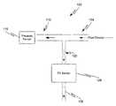
- FIG. 1is a block diagram depicting a tilt sensor in accordance with at least some embodiments of the present invention
- FIG. 2is a flow chart depicting a periodic tilt sensing method in accordance with at least some embodiments of the present invention
- FIG. 3is a flow chart depicting a continuous tilt sensing method in accordance with at least some embodiments of the present invention.
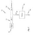
- FIG. 4is a cross-sectional perspective view of an exemplary tilt sensor in accordance with at least some embodiments of the present invention.
- FIG. 1an exemplary tilt sensor circuit will be described in accordance with at least some embodiments of the present invention. While certain embodiments of the present invention will be discussed in connection with measuring and monitoring the orientation of a component or collection of components in a ventilator system, one skilled in the art will appreciate that embodiments of the present invention may be equally useful in measuring and monitoring the orientation of any type of object or collection of objects, including other medical devices.
- the tilt-sensing system 100may be adapted to attach or be otherwise rigidly associated with a ventilator system used to assist breathing functions of a patient.
- the ventilator systemmay include a ventilator (not shown) connected to a fluidic circuit that is separate from the patient circuit.
- a pressure sensor 116may be provided on an output branch 112 of the tilt-sensing system 100 .
- the tilt-sensing system 100may also include an input branch 104 having a fluid (e.g., air, gas, etc.) source and a tilt sensor input branch 120 .
- the pressure sensor 116may be operable to detect fluidic pressure within the output branch 112 and report some value that is an indication of the detected fluid flow through the tilt sensor 124 or pressure in the circuit.
- the senor 116may be a differential pressure sensor, a collection of individual pressure sensors located at various points along the circuit, or any other type of pressure measuring device.
- the pressure sensor 116is remotely connected to the tilt sensor 124 via a flexible, possibly thin, tube.
- the tilt sensor 124may be rigidly attached to an object having it's tilt monitored.
- the pressure sensor 116may be rigidly attached to an object having it's tilt monitored while in other embodiments the pressure sensor 116 may not be connected to the object at all.
- the tilt sensor 124may be associated with (e.g., rigidly attached to) a component of a ventilator system by being physically connected to the component of the ventilator system.
- the tilt sensor 124may be connected to the pressure sensor 116 possibly through long, flexible tubing 120 such that alterations in the orientation of the proximal flow sensor (not shown) are detected by the tilt sensor 124 (e.g., because the orientation of the tilt sensor 124 is altered).
- Tilt sensor 124may be coupled to the ventilation component using a wide variety of coupling devices or methods, including snap-together connectors, straps, cables, adhesives, and the like. In other embodiments, the tilt sensor 124 may be an integral part of the pressure sensor 116 .
- fluid flow to the tilt sensor 124may be provided by an external source and not from the patient circuit (e.g., from a separate fluid source).
- the input port 120 of the tilt sensor 124may be in communication with a primary fluid flow path in the tilt-sensing system 100 .
- the tilt sensor 124is adapted to detect whether a component(s) of an associated device (e.g., proximal flow sensor) is in a tilted or non-tilted state.
- the tilt sensor 124is employed to give an early warning that the orientation of a component in the ventilator system to reduce the possibility that secretions might start to reduce the accuracy of patient airway flow measurements.
- a properly designed tilt sensor 124can be used to alert users and/or technicians that ventilation flow measurements may be compromised due to the improper orientation of the tilt sensor 124 . It is useful to obtain this early detection to help prevent any diagnosis based on inaccurate ventilation flow measurements.
- tilt sensormay be used in connection with measuring the orientation of components in a ventilator system.
- the tilt sensor 124may be pneumatically operated and adapted to work in cooperation with the fluid flowing through the primary flow path.
- Other types of tilt sensormay also be useful to use alone or in combination with a pneumatically operated tilt sensor 124 in certain embodiments of the present invention.
- FIG. 4One exemplary embodiment of the tilt sensor 124 is depicted in FIG. 4 .
- a tilt sensor 124is depicted that includes an inclined surface 132 that transitions into an orifice or tilt sensor output 120 .
- the tilt sensor 124may also include a flow stopping member 136 that is operable to engage with and cover the orifice 120 when the tilt sensor 124 is in a preferred orientation (i.e., a non-tilt orientation in this case).
- the inclined surface 132may be designed such that the weight of the flow stopping member 136 brings the flow stopping member 136 over the orifice 120 .
- the flow stopping membermay have a slightly larger external dimension than the dimensions of the orifice 120 .
- the flow stopping member 136may comprise a spherical element, such as a ball.
- a pressure or flow sensor disposed within or in communication with the tilt sensor 124can detect a non-tilted orientation of tilt sensor 124 and communicate this information to the ventilator system.
- the pressure and/or flow sensor disposed within or in communication with the tilt sensor 124detects the tilted orientation and communicates this data to the ventilator system.
- Such embodimentsmay be particularly useful, for example, when it is desired to know the orientation of a component of a ventilation circuit.
- the flow stopping member 136 and/or orifice 120 and/or inclined surface 132 and/or housing 124may assume any number of different configurations. Examples of some alternative configurations for the flow stopping member 136 include, without limitation, a washer, a donut, a ring, a cylinder, or any other object that can roll down the inclined surface 132 under its own weight.
- the orifice 120may be designed to receive and be blocked by any type of flow stopping member 136 that is employed. For instance, if the flow stopping member 136 is designed like a ring, then the orifice 120 may be a slot whose length is less than the diameter of the ring and whose width is less than or equal to the thickness of the ring.
- the inclined surfaces 124 of the tilt sensor 124may comprise a conical shape.
- the tilt sensor 124may be adapted to detect tilt about any plane whereas a tilt sensor 124 with a ring or donut flow stopping member 136 may only be enabled to detect tilt about one plane.
- the tilt sensor 124is designed to cause the flow stopping member 136 to wander out of the orifice 120 after the tilt sensor 124 has been tilted a predetermined angle.
- This predetermined anglemay be determined by the geometry of the stopping member 136 , the weight of the stopping member 136 , the type of material used to create the stopping member 136 , the geometry and texture of the inclined surface 132 , and the amount and type of fluid flowing in the system 104 . With a proper design of the stopping member 136 , orifice 120 , and inclined surface 132 it can be determined what angle of tilt will cause fluid to flow through the orifice 120 .
- the inclined surfaces 132 of the tilt sensor 124may comprise a number of different surfaces having a number of different angles of inclination.
- the angle of inclinationi.e., the angle between the surface of the inclined surface 132 and a plane which is either orthogonal to the path of fluid flow through the orifice 120 or parallel to the base of the tilt sensor 124
- the angle of inclination of the inclined surface 132may be between about ten (10) degrees and about fifteen (15) degrees. Based on the properties of the flow stopping member 136 and inclined surface 132 , these angles of inclination may correspond to operational tilt angles between ten (10) degrees and forty (40) degrees.
- An operational tilt anglediffers from the angle of inclination of the inclined surface 132 in that the operational tilt angle is the angle at which the tilt sensor 124 needs to be tilted to cause the state of the tilt sensor 124 to change from tilted to non-tilted or vice versa, whereas the angle of inclination corresponds to the physical angle at which the inclined surface 132 is oriented.
- the inclined surfaces 124may be designed such that precise control over when the orifice 120 is blocked or not can be obtained and the angle of inclination causing the flow stopping member 136 to move out of the orifice 120 may be different from the angle of inclination causing the flow stopping member 136 to move back over the orifice 120 .
- a tilt of forty (40) degrees off verticalmay cause the flow stopping member 136 to move away from the orifice 120 whereas a tilt of twenty (20) degrees is required to cause the flow stopping member 136 to move back into the orifice 120 after it is out of the orifice 120 .
- Thismay be facilitated by employing multiple inclined surfaces 124 each having different angles of inclination.
- the tilt sensor 124can be designed to have two angles where the tilt activates and deactivates. The dual angles of inclination can help create an anti-chatter mechanism that allows the tilt sensor 124 to tolerate a certain amount of patient movement without switching between a tilted state and non-tilted state.
- a pressure sensor 116is shown being connected to output branch 112 of the tilt-sensing system 110 , a flow sensor may be used as an alternative to the pressure sensor 116 .
- a flow sensor or series of flow sensorsmay be used in combination with a pressure sensor 116 or series of pressure sensors without departing from the scope of the present invention.
- the methodbegins by determining a suitable tilt/non-tilt threshold (step 204 ).
- This thresholdis defined by the properties of the tilt sensor 124 and/or properties used to actuate the tilt sensor 124 .
- the threshold used to determine whether the tilt sensor 124 is in a tilted orientationmay include a predetermined flow and/or pressure measurement that is measured by the pressure sensor 116 .
- the methodcontinues when it becomes time to test the orientation of the tilt sensor 124 (step 208 ) at which time fluid is flowed toward the tilt sensor 124 in the tilt sensor flow path 120 (step 212 ).
- the fluidmay include, but is not limited to, wall air, gas from a compressor, or gas from a tank.
- the pressure sensor 116monitors the pressure in the tilt sensor flow path 120 and the primary flow path (step 216 ).
- the measured pressureis then compared to the predetermined tilt threshold (step 220 ) to determine whether the tilt sensor 124 is in a tilted or non-tilted state. Since the tilt sensor 124 is also associated with some other component or collection of components (e.g., a ventilator system component such as a proximal flow sensor), the orientation of that component can be inferred by determining the orientation of the tilt sensor 124 .
- a ventilator system componentsuch as a proximal flow sensor
- a non-tilted orientationis reported for the tilt sensor 124 (step 224 ).
- a tilted orientationis reported for the tilt sensor 124 (step 228 ). Once the tilt orientation has been reported the method ends (step 228 ) until the next time a tilt test is performed.
- the methodincludes receiving fluid flow in a primary fluid flow path (step 304 ). Thereafter, the method determines the pressure threshold for identifying a reduced pressure state in the primary flow path (i.e., a tilted state) and a normal pressure state in the primary flow path (i.e., a non-tilted state) (step 308 ).
- a tilt state pressure thresholdis determined for both a tilted state and a non-tilted state.
- the threshold or trigger identified in step 308may vary depending upon the type of pressure sensor being used in the primary flow path as well as the location of the tilt sensor 124 .
- the methodcontinues with the pressure sensor 116 monitoring the pressure of the fluid flow in the primary fluid flow path for a reduced pressure (step 312 ) until a reduced pressure is detected (step 316 ).
- a reduced pressurei.e., the pressure measured at the pressure sensor 116 has fallen below a predetermined tilt state pressure threshold
- the methodincludes the tilt sensor 124 reporting a tilted orientation of the tilt sensor 124 (step 320 ). This may be reported in a buzzer, light, or other type of audible/visible indication to a user. Alternatively, the tilt may be reported to a remote location and may also be stored in a tilt log.
- the methodincludes monitoring the pressure of the primary flow path for an increase in pressure (step 324 ) until a return to normal pressure conditions has been detected (i.e., the pressure measured at the pressure sensor 116 has risen above the predetermined tilt state pressure threshold)(step 328 ).
- this triggermay correspond to detecting an increase in the pressure in the primary flow path 108 , 112 .
- the methodincludes identifying and reporting the non-tilted orientation of the tilt sensor (step 332 ). Then the method returns to step 312 .
- the tilt sensor 124comprises two separate components that are adapted to cooperate with one another and form a cavity, which may or may not be air-tight, for the flow stopping member 136 .
- the orifice 120 of the tilt sensor 124which is adapted to be blocked by the flow stopping member 136 in a non-tilted orientation may have the inclined surface 132 that biases the flow stopping member 136 toward the orifice 120 .
- the opposite orifice of the tilt sensor 124i.e., the orifice of the upper component depicted in FIG. 4
- the deterrent tilted surfacesare useful to prevent the tilt sensor 124 from providing erroneous pressure data in an upside-down configuration. More specifically, if the tilt sensor 124 were completely upside-down, the deterrent tilted surfaces may prevent the flow stopping member 136 from stopping the flow of fluid through the tilt sensor 124 , thereby preventing a false non-tilted orientation reading.
- an “ON-OFF” switch for the tilt sensor 124may also be provided. It may be advantageous to have some means of sampling the state of the tilt sensor 124 by turning the gas ON, measuring the pressure, then turning the gas OFF. Because if it were ON continuously the gas pressure would keep the flow stopping member 136 in its seat and not let it wander away during a TILT condition. However, if the flow stopping member 136 were heavy enough, and the gas pressure were low enough, in that case it could work without a means for interrupting the gas flow.
- tilt sensor 124may be useful is in explosive environments, where electrically operated tilt sensors run the risk of malfunction and creating a spark, causing an explosion, or any application where tilt sensing is needed in a sensitive area, such as near a patient being ventilated, without the use of electrical wiring directly to the tilt sensor.
Landscapes
- Health & Medical Sciences (AREA)
- Emergency Medicine (AREA)
- Pulmonology (AREA)
- Engineering & Computer Science (AREA)
- Anesthesiology (AREA)
- Biomedical Technology (AREA)
- Heart & Thoracic Surgery (AREA)
- Hematology (AREA)
- Life Sciences & Earth Sciences (AREA)
- Animal Behavior & Ethology (AREA)
- General Health & Medical Sciences (AREA)
- Public Health (AREA)
- Veterinary Medicine (AREA)
- Physics & Mathematics (AREA)
- Fluid Mechanics (AREA)
- General Physics & Mathematics (AREA)
- Measuring Volume Flow (AREA)
Abstract
Description
Claims (18)
Priority Applications (4)
| Application Number | Priority Date | Filing Date | Title |
|---|---|---|---|
| CA2738212ACA2738212A1 (en) | 2008-09-30 | 2009-09-30 | Pneumatic tilt sensor for use with respiratory flow sensing device |
| PCT/US2009/059102WO2010039884A1 (en) | 2008-09-30 | 2009-09-30 | Pneumatic tilt sensor for use with respiratory flow sensing device |
| US12/570,956US8113062B2 (en) | 2008-09-30 | 2009-09-30 | Tilt sensor for use with proximal flow sensing device |
| EP09793206AEP2329232B1 (en) | 2008-09-30 | 2009-09-30 | Pneumatic tilt sensor for use with respiratory flow sensing device |
Applications Claiming Priority (2)
| Application Number | Priority Date | Filing Date | Title |
|---|---|---|---|
| US10119008P | 2008-09-30 | 2008-09-30 | |
| US12/570,956US8113062B2 (en) | 2008-09-30 | 2009-09-30 | Tilt sensor for use with proximal flow sensing device |
Related Parent Applications (1)
| Application Number | Title | Priority Date | Filing Date |
|---|---|---|---|
| US10119008PDivision | 2008-09-30 | 2008-09-30 |
Publications (2)
| Publication Number | Publication Date |
|---|---|
| US20100077866A1 US20100077866A1 (en) | 2010-04-01 |
| US8113062B2true US8113062B2 (en) | 2012-02-14 |
Family
ID=41278696
Family Applications (1)
| Application Number | Title | Priority Date | Filing Date |
|---|---|---|---|
| US12/570,956Expired - Fee RelatedUS8113062B2 (en) | 2008-09-30 | 2009-09-30 | Tilt sensor for use with proximal flow sensing device |
Country Status (4)
| Country | Link |
|---|---|
| US (1) | US8113062B2 (en) |
| EP (1) | EP2329232B1 (en) |
| CA (1) | CA2738212A1 (en) |
| WO (1) | WO2010039884A1 (en) |
Cited By (95)
| Publication number | Priority date | Publication date | Assignee | Title |
|---|---|---|---|---|
| US20100051029A1 (en)* | 2008-09-04 | 2010-03-04 | Nellcor Puritan Bennett Llc | Inverse Sawtooth Pressure Wave Train Purging In Medical Ventilators |
| US20100071696A1 (en)* | 2008-09-25 | 2010-03-25 | Nellcor Puritan Bennett Llc | Model-predictive online identification of patient respiratory effort dynamics in medical ventilators |
| US20100147303A1 (en)* | 2008-03-31 | 2010-06-17 | Nellcor Puritan Bennett Llc | Determination of patient circuit disconnect in leak-compensated ventilatory support |
| US20100186744A1 (en)* | 2003-07-29 | 2010-07-29 | Claude Andrieux | System and process for supplying respiratory gas under pressure or volumetrically |
| US20100218767A1 (en)* | 2009-02-27 | 2010-09-02 | Nellcor Puritan Bennett Llc | Leak-compensated respiratory mechanics estimation in medical ventilators |
| US20110023878A1 (en)* | 2009-07-31 | 2011-02-03 | Nellcor Puritan Bennett Llc | Method And System For Delivering A Single-Breath, Low Flow Recruitment Maneuver |
| US20110041850A1 (en)* | 2009-08-20 | 2011-02-24 | Nellcor Puritan Bennett Llc | Method For Ventilation |
| US20110126834A1 (en)* | 2009-12-01 | 2011-06-02 | Nellcor Puritan Bennett Llc | Exhalation Valve Assembly With Integral Flow Sensor |
| US20110126837A1 (en)* | 2009-12-01 | 2011-06-02 | Nellcor Puritan Bennett Llc | Exhalation Valve Assembly With Integrated Filter |
| US20110126835A1 (en)* | 2009-12-01 | 2011-06-02 | Nellcor Puritan Bennett Llc | Exhalation Valve Assembly With Integrated Filter And Flow Sensor |
| US20110128008A1 (en)* | 2009-12-02 | 2011-06-02 | Nellcor Puritan Bennett Llc | Method And Apparatus For Indicating Battery Cell Status On A Battery Pack Assembly Used During Mechanical Ventilation |
| US20110132371A1 (en)* | 2009-12-04 | 2011-06-09 | Nellcor Puritan Bennett, LLC. | Alarm Indication System |
| US20110138311A1 (en)* | 2009-12-04 | 2011-06-09 | Nellcor Puritan Bennett Llc | Display Of Respiratory Data On A Ventilator Graphical User Interface |
| US20110132367A1 (en)* | 2009-12-03 | 2011-06-09 | Nellcor Puritan Bennett Llc | Ventilator Respiratory Variable-Sized Gas Accumulator |
| US20110138308A1 (en)* | 2009-12-04 | 2011-06-09 | Nellcor Puritan Bennett Llc | Display And Access To Settings On A Ventilator Graphical User Interface |
| US20110132362A1 (en)* | 2009-12-04 | 2011-06-09 | Nellcor Puritan Bennett Llc | Ventilation System With System Status Display Including A User Interface |
| US20110138323A1 (en)* | 2009-12-04 | 2011-06-09 | Nellcor Puritan Bennett Llc | Visual Indication Of Alarms On A Ventilator Graphical User Interface |
| US20110146681A1 (en)* | 2009-12-21 | 2011-06-23 | Nellcor Puritan Bennett Llc | Adaptive Flow Sensor Model |
| US20110146683A1 (en)* | 2009-12-21 | 2011-06-23 | Nellcor Puritan Bennett Llc | Sensor Model |
| US20110175728A1 (en)* | 2010-01-19 | 2011-07-21 | Nellcor Puritan Bennett Llc | Nuisance Alarm Reduction Method For Therapeutic Parameters |
| US20110209702A1 (en)* | 2010-02-26 | 2011-09-01 | Nellcor Puritan Bennett Llc | Proportional Solenoid Valve For Low Molecular Weight Gas Mixtures |
| US20110213215A1 (en)* | 2010-02-26 | 2011-09-01 | Nellcor Puritan Bennett Llc | Spontaneous Breathing Trial Manager |
| US8434480B2 (en) | 2008-03-31 | 2013-05-07 | Covidien Lp | Ventilator leak compensation |
| US8443294B2 (en) | 2009-12-18 | 2013-05-14 | Covidien Lp | Visual indication of alarms on a ventilator graphical user interface |
| US8448641B2 (en) | 2009-03-20 | 2013-05-28 | Covidien Lp | Leak-compensated proportional assist ventilation |
| US8453643B2 (en) | 2010-04-27 | 2013-06-04 | Covidien Lp | Ventilation system with system status display for configuration and program information |
| US8453645B2 (en) | 2006-09-26 | 2013-06-04 | Covidien Lp | Three-dimensional waveform display for a breathing assistance system |
| US8469030B2 (en) | 2009-12-01 | 2013-06-25 | Covidien Lp | Exhalation valve assembly with selectable contagious/non-contagious latch |
| US8485185B2 (en) | 2008-06-06 | 2013-07-16 | Covidien Lp | Systems and methods for ventilation in proportion to patient effort |
| US8511306B2 (en) | 2010-04-27 | 2013-08-20 | Covidien Lp | Ventilation system with system status display for maintenance and service information |
| US8539949B2 (en) | 2010-04-27 | 2013-09-24 | Covidien Lp | Ventilation system with a two-point perspective view |
| US8554298B2 (en) | 2010-09-21 | 2013-10-08 | Cividien LP | Medical ventilator with integrated oximeter data |
| US8555882B2 (en) | 1997-03-14 | 2013-10-15 | Covidien Lp | Ventilator breath display and graphic user interface |
| USD692556S1 (en) | 2013-03-08 | 2013-10-29 | Covidien Lp | Expiratory filter body of an exhalation module |
| USD693001S1 (en) | 2013-03-08 | 2013-11-05 | Covidien Lp | Neonate expiratory filter assembly of an exhalation module |
| US8595639B2 (en) | 2010-11-29 | 2013-11-26 | Covidien Lp | Ventilator-initiated prompt regarding detection of fluctuations in resistance |
| US8597198B2 (en) | 2006-04-21 | 2013-12-03 | Covidien Lp | Work of breathing display for a ventilation system |
| US8607790B2 (en) | 2010-06-30 | 2013-12-17 | Covidien Lp | Ventilator-initiated prompt regarding auto-PEEP detection during pressure ventilation of patient exhibiting obstructive component |
| US8607791B2 (en) | 2010-06-30 | 2013-12-17 | Covidien Lp | Ventilator-initiated prompt regarding auto-PEEP detection during pressure ventilation |
| US8607788B2 (en) | 2010-06-30 | 2013-12-17 | Covidien Lp | Ventilator-initiated prompt regarding auto-PEEP detection during volume ventilation of triggering patient exhibiting obstructive component |
| US8607789B2 (en) | 2010-06-30 | 2013-12-17 | Covidien Lp | Ventilator-initiated prompt regarding auto-PEEP detection during volume ventilation of non-triggering patient exhibiting obstructive component |
| US8638200B2 (en) | 2010-05-07 | 2014-01-28 | Covidien Lp | Ventilator-initiated prompt regarding Auto-PEEP detection during volume ventilation of non-triggering patient |
| US8676285B2 (en) | 2010-07-28 | 2014-03-18 | Covidien Lp | Methods for validating patient identity |
| US8676529B2 (en) | 2011-01-31 | 2014-03-18 | Covidien Lp | Systems and methods for simulation and software testing |
| USD701601S1 (en) | 2013-03-08 | 2014-03-25 | Covidien Lp | Condensate vial of an exhalation module |
| US8707952B2 (en) | 2010-02-10 | 2014-04-29 | Covidien Lp | Leak determination in a breathing assistance system |
| US8714154B2 (en) | 2011-03-30 | 2014-05-06 | Covidien Lp | Systems and methods for automatic adjustment of ventilator settings |
| US8720442B2 (en) | 2008-09-26 | 2014-05-13 | Covidien Lp | Systems and methods for managing pressure in a breathing assistance system |
| US8757153B2 (en) | 2010-11-29 | 2014-06-24 | Covidien Lp | Ventilator-initiated prompt regarding detection of double triggering during ventilation |
| US8757152B2 (en) | 2010-11-29 | 2014-06-24 | Covidien Lp | Ventilator-initiated prompt regarding detection of double triggering during a volume-control breath type |
| US8776792B2 (en) | 2011-04-29 | 2014-07-15 | Covidien Lp | Methods and systems for volume-targeted minimum pressure-control ventilation |
| US8783250B2 (en) | 2011-02-27 | 2014-07-22 | Covidien Lp | Methods and systems for transitory ventilation support |
| US8788236B2 (en) | 2011-01-31 | 2014-07-22 | Covidien Lp | Systems and methods for medical device testing |
| US8844526B2 (en) | 2012-03-30 | 2014-09-30 | Covidien Lp | Methods and systems for triggering with unknown base flow |
| US8950398B2 (en) | 2008-09-30 | 2015-02-10 | Covidien Lp | Supplemental gas safety system for a breathing assistance system |
| US8973577B2 (en) | 2009-03-20 | 2015-03-10 | Covidien Lp | Leak-compensated pressure regulated volume control ventilation |
| US9022031B2 (en) | 2012-01-31 | 2015-05-05 | Covidien Lp | Using estimated carinal pressure for feedback control of carinal pressure during ventilation |
| US9027552B2 (en) | 2012-07-31 | 2015-05-12 | Covidien Lp | Ventilator-initiated prompt or setting regarding detection of asynchrony during ventilation |
| US9038633B2 (en) | 2011-03-02 | 2015-05-26 | Covidien Lp | Ventilator-initiated prompt regarding high delivered tidal volume |
| USD731048S1 (en) | 2013-03-08 | 2015-06-02 | Covidien Lp | EVQ diaphragm of an exhalation module |
| USD731065S1 (en) | 2013-03-08 | 2015-06-02 | Covidien Lp | EVQ pressure sensor filter of an exhalation module |
| USD731049S1 (en) | 2013-03-05 | 2015-06-02 | Covidien Lp | EVQ housing of an exhalation module |
| US9089657B2 (en) | 2011-10-31 | 2015-07-28 | Covidien Lp | Methods and systems for gating user initiated increases in oxygen concentration during ventilation |
| USD736905S1 (en) | 2013-03-08 | 2015-08-18 | Covidien Lp | Exhalation module EVQ housing |
| US9119925B2 (en) | 2009-12-04 | 2015-09-01 | Covidien Lp | Quick initiation of respiratory support via a ventilator user interface |
| US9144658B2 (en) | 2012-04-30 | 2015-09-29 | Covidien Lp | Minimizing imposed expiratory resistance of mechanical ventilator by optimizing exhalation valve control |
| USD744095S1 (en) | 2013-03-08 | 2015-11-24 | Covidien Lp | Exhalation module EVQ internal flow sensor |
| US9262588B2 (en) | 2009-12-18 | 2016-02-16 | Covidien Lp | Display of respiratory data graphs on a ventilator graphical user interface |
| US9289573B2 (en) | 2012-12-28 | 2016-03-22 | Covidien Lp | Ventilator pressure oscillation filter |
| US9302061B2 (en) | 2010-02-26 | 2016-04-05 | Covidien Lp | Event-based delay detection and control of networked systems in medical ventilation |
| US9327089B2 (en) | 2012-03-30 | 2016-05-03 | Covidien Lp | Methods and systems for compensation of tubing related loss effects |
| US9358355B2 (en) | 2013-03-11 | 2016-06-07 | Covidien Lp | Methods and systems for managing a patient move |
| US9364624B2 (en) | 2011-12-07 | 2016-06-14 | Covidien Lp | Methods and systems for adaptive base flow |
| US9375542B2 (en) | 2012-11-08 | 2016-06-28 | Covidien Lp | Systems and methods for monitoring, managing, and/or preventing fatigue during ventilation |
| US9381314B2 (en) | 2008-09-23 | 2016-07-05 | Covidien Lp | Safe standby mode for ventilator |
| US9492629B2 (en) | 2013-02-14 | 2016-11-15 | Covidien Lp | Methods and systems for ventilation with unknown exhalation flow and exhalation pressure |
| US9498589B2 (en) | 2011-12-31 | 2016-11-22 | Covidien Lp | Methods and systems for adaptive base flow and leak compensation |
| USD775345S1 (en) | 2015-04-10 | 2016-12-27 | Covidien Lp | Ventilator console |
| US9629971B2 (en) | 2011-04-29 | 2017-04-25 | Covidien Lp | Methods and systems for exhalation control and trajectory optimization |
| US9649458B2 (en) | 2008-09-30 | 2017-05-16 | Covidien Lp | Breathing assistance system with multiple pressure sensors |
| US9675771B2 (en) | 2013-10-18 | 2017-06-13 | Covidien Lp | Methods and systems for leak estimation |
| US9808591B2 (en) | 2014-08-15 | 2017-11-07 | Covidien Lp | Methods and systems for breath delivery synchronization |
| US9820681B2 (en) | 2008-03-31 | 2017-11-21 | Covidien Lp | Reducing nuisance alarms |
| US9925346B2 (en) | 2015-01-20 | 2018-03-27 | Covidien Lp | Systems and methods for ventilation with unknown exhalation flow |
| US9950135B2 (en) | 2013-03-15 | 2018-04-24 | Covidien Lp | Maintaining an exhalation valve sensor assembly |
| US9950129B2 (en) | 2014-10-27 | 2018-04-24 | Covidien Lp | Ventilation triggering using change-point detection |
| US9981096B2 (en) | 2013-03-13 | 2018-05-29 | Covidien Lp | Methods and systems for triggering with unknown inspiratory flow |
| US9993604B2 (en) | 2012-04-27 | 2018-06-12 | Covidien Lp | Methods and systems for an optimized proportional assist ventilation |
| US20180238685A1 (en)* | 2015-09-02 | 2018-08-23 | Seiko Instruments Inc. | Tilt sensor |
| US10064583B2 (en) | 2013-08-07 | 2018-09-04 | Covidien Lp | Detection of expiratory airflow limitation in ventilated patient |
| US10207069B2 (en) | 2008-03-31 | 2019-02-19 | Covidien Lp | System and method for determining ventilator leakage during stable periods within a breath |
| US10362967B2 (en) | 2012-07-09 | 2019-07-30 | Covidien Lp | Systems and methods for missed breath detection and indication |
| US10668239B2 (en) | 2017-11-14 | 2020-06-02 | Covidien Lp | Systems and methods for drive pressure spontaneous ventilation |
| US10765822B2 (en) | 2016-04-18 | 2020-09-08 | Covidien Lp | Endotracheal tube extubation detection |
| US11674727B2 (en) | 2021-07-23 | 2023-06-13 | Goodman Manufacturing Company, L.P. | HVAC equipment with refrigerant gas sensor |
Families Citing this family (26)
| Publication number | Priority date | Publication date | Assignee | Title |
|---|---|---|---|---|
| US10918308B2 (en)* | 2007-05-18 | 2021-02-16 | Koninklijke Philips N.V. | Respiratory component measurement system including a sensor for detecting orientation or motion |
| US9026370B2 (en) | 2007-12-18 | 2015-05-05 | Hospira, Inc. | User interface improvements for medical devices |
| US9521963B2 (en)* | 2008-05-13 | 2016-12-20 | Ric Investments, Llc | Respiratory component measurement system with indicating elements |
| US8485179B1 (en) | 2009-02-23 | 2013-07-16 | Trudell Medical International | Oscillating positive expiratory pressure device |
| US9149589B2 (en)* | 2009-02-23 | 2015-10-06 | Trudell Medical International | Method and device for performing orientation dependent oscillating positive expiratory pressure therapy |
| AU2012299169B2 (en) | 2011-08-19 | 2017-08-24 | Icu Medical, Inc. | Systems and methods for a graphical interface including a graphical representation of medical data |
| MX342940B (en) | 2011-09-30 | 2016-10-19 | Hospira Inc | Intravenous flow rate controller. |
| US10022498B2 (en) | 2011-12-16 | 2018-07-17 | Icu Medical, Inc. | System for monitoring and delivering medication to a patient and method of using the same to minimize the risks associated with automated therapy |
| DE102011089846A1 (en)* | 2011-12-23 | 2013-06-27 | Endress + Hauser Gmbh + Co. Kg | Tilt sensor for a transmitter, transmitter with an inclination detector interface, and method for determining the inclination of a transmitter |
| JP6306566B2 (en) | 2012-03-30 | 2018-04-04 | アイシーユー・メディカル・インコーポレーテッド | Air detection system and method for detecting air in an infusion system pump |
| AU2013296555B2 (en) | 2012-07-31 | 2017-10-19 | Icu Medical, Inc. | Patient care system for critical medications |
| AU2014268355B2 (en) | 2013-05-24 | 2018-06-14 | Icu Medical, Inc. | Multi-sensor infusion system for detecting air or an occlusion in the infusion system |
| WO2014194065A1 (en) | 2013-05-29 | 2014-12-04 | Hospira, Inc. | Infusion system and method of use which prevents over-saturation of an analog-to-digital converter |
| US10166328B2 (en) | 2013-05-29 | 2019-01-01 | Icu Medical, Inc. | Infusion system which utilizes one or more sensors and additional information to make an air determination regarding the infusion system |
| EP3110474B1 (en) | 2014-02-28 | 2019-12-18 | ICU Medical, Inc. | Infusion system and method which utilizes dual wavelength optical air-in-line detection |
| US11344673B2 (en) | 2014-05-29 | 2022-05-31 | Icu Medical, Inc. | Infusion system and pump with configurable closed loop delivery rate catch-up |
| US11344668B2 (en) | 2014-12-19 | 2022-05-31 | Icu Medical, Inc. | Infusion system with concurrent TPN/insulin infusion |
| US10850024B2 (en) | 2015-03-02 | 2020-12-01 | Icu Medical, Inc. | Infusion system, device, and method having advanced infusion features |
| CA3023658C (en) | 2016-05-13 | 2023-03-07 | Icu Medical, Inc. | Infusion pump system and method with common line auto flush |
| WO2017214441A1 (en) | 2016-06-10 | 2017-12-14 | Icu Medical, Inc. | Acoustic flow sensor for continuous medication flow measurements and feedback control of infusion |
| US10089055B1 (en) | 2017-12-27 | 2018-10-02 | Icu Medical, Inc. | Synchronized display of screen content on networked devices |
| US11278671B2 (en) | 2019-12-04 | 2022-03-22 | Icu Medical, Inc. | Infusion pump with safety sequence keypad |
| CA3189781A1 (en) | 2020-07-21 | 2022-01-27 | Icu Medical, Inc. | Fluid transfer devices and methods of use |
| US11135360B1 (en) | 2020-12-07 | 2021-10-05 | Icu Medical, Inc. | Concurrent infusion with common line auto flush |
| USD1091564S1 (en) | 2021-10-13 | 2025-09-02 | Icu Medical, Inc. | Display screen or portion thereof with graphical user interface for a medical device |
| CA3241894A1 (en) | 2021-12-10 | 2023-06-15 | Icu Medical, Inc. | Medical fluid compounding systems with coordinated flow control |
Citations (67)
| Publication number | Priority date | Publication date | Assignee | Title |
|---|---|---|---|---|
| US5038621A (en) | 1989-11-06 | 1991-08-13 | Bicore Monitoring Systems | Variable area obstruction gas flow meter |
| US5146092A (en) | 1990-05-23 | 1992-09-08 | Ntc Technology, Inc. | Gas analysis transducers with electromagnetic energy detector units |
| US5153436A (en) | 1990-05-23 | 1992-10-06 | Ntc Technology, Inc. | Temperature controlled detectors for infrared-type gas analyzers |
| US5316009A (en) | 1991-07-05 | 1994-05-31 | Nihon Kohden Corporation | Apparatus for monitoring respiratory muscle activity |
| US5369277A (en) | 1990-05-23 | 1994-11-29 | Ntc Technology, Inc. | Infrared source |
| EP0728493A1 (en) | 1995-02-27 | 1996-08-28 | Siemens-Elema AB | Ventilator/anaesthetic system |
| US5616923A (en) | 1990-05-23 | 1997-04-01 | Novametrix Medical Systems Inc. | Gas analyzer cuvettes |
| US5693944A (en) | 1994-09-02 | 1997-12-02 | Ntc Technology, Inc. | Gas analyzer cuvettes |
| EP0850652A2 (en) | 1996-12-19 | 1998-07-01 | Respiratory Support Products Inc. | Endotracheal pressure monitoring and medication system |
| US5789660A (en) | 1996-07-15 | 1998-08-04 | Novametrix Medical Systems, Inc. | Multiple function airway adapter |
| US6095140A (en) | 1998-04-09 | 2000-08-01 | Massachusetts Institute Of Technology | Ventilator triggering device |
| US6099481A (en) | 1997-11-03 | 2000-08-08 | Ntc Technology, Inc. | Respiratory profile parameter determination method and apparatus |
| US6106480A (en) | 1996-09-28 | 2000-08-22 | Technische Universitaet Dresden | Device to determine effective pulmonary blood flow |
| US6155986A (en) | 1995-06-08 | 2000-12-05 | Resmed Limited | Monitoring of oro-nasal respiration |
| US6203502B1 (en) | 1997-03-31 | 2001-03-20 | Pryon Corporation | Respiratory function monitor |
| US6227196B1 (en) | 1996-12-19 | 2001-05-08 | Ntc Technology Inc. | Apparatus and method for non-invasively measuring cardiac output |
| US6325978B1 (en) | 1998-08-04 | 2001-12-04 | Ntc Technology Inc. | Oxygen monitoring and apparatus |
| US6358215B1 (en) | 1997-10-18 | 2002-03-19 | Cardiopulmonary Technologies, Inc. | Infrared gas content analyzing apparatus |
| JP2002136595A (en) | 2000-10-31 | 2002-05-14 | Nippon Applied Flow Kk | Respiratory flow meter |
| US6390091B1 (en) | 1999-02-03 | 2002-05-21 | University Of Florida | Method and apparatus for controlling a medical ventilator |
| US6402697B1 (en) | 1999-01-21 | 2002-06-11 | Metasensors, Inc. | Non-invasive cardiac output and pulmonary function monitoring using respired gas analysis techniques and physiological modeling |
| US6408848B1 (en) | 2000-03-28 | 2002-06-25 | Ntc Technology, Inc. | Method and apparatus for conveniently setting a predetermined volume for re-breathing |
| EP1228779A1 (en) | 2001-02-01 | 2002-08-07 | Instrumentarium Corporation | Method and apparatus for determining a zero gas flow state in a bidirectional gas flow conduit |
| US20030047188A1 (en) | 2001-09-07 | 2003-03-13 | Respironics, Inc. | Face mask for gas monitoring during supplemental oxygen delivery |
| US6540689B1 (en) | 2000-02-22 | 2003-04-01 | Ntc Technology, Inc. | Methods for accurately, substantially noninvasively determining pulmonary capillary blood flow, cardiac output, and mixed venous carbon dioxide content |
| US6575164B1 (en) | 1998-10-15 | 2003-06-10 | Ntc Technology, Inc. | Reliability-enhanced apparatus operation for re-breathing and methods of effecting same |
| US6629934B2 (en) | 2000-02-02 | 2003-10-07 | Healthetech, Inc. | Indirect calorimeter for medical applications |
| US20030191405A1 (en) | 2002-04-04 | 2003-10-09 | Ric Investments, Inc. | Sidestream gas sampling system with detachable sample cell |
| US20040003814A1 (en) | 2000-08-17 | 2004-01-08 | Banner Michael J. | Endotracheal tube pressure monitoring system and method of controlling same |
| US20040087867A1 (en) | 1996-09-28 | 2004-05-06 | Marcelo Gama De Abreu | Arrangement for the determination of the effective pulmonary blood flow |
| US20040186391A1 (en) | 2003-02-21 | 2004-09-23 | Pierry Anthony T. | Gas monitoring system and sidestream gas measurement system adapted to communicate with a mainstream gas measurement system |
| US6815211B1 (en) | 1998-08-04 | 2004-11-09 | Ntc Technology | Oxygen monitoring methods and apparatus (I) |
| US20040256560A1 (en) | 2003-03-07 | 2004-12-23 | Russell James T. | Optical system for a gas measurement system |
| US20050154320A1 (en)* | 2004-01-09 | 2005-07-14 | Froelich Michael A. | Methods and devices for accurate pressure monitoring |
| US6945123B1 (en) | 2004-06-28 | 2005-09-20 | The General Electric Company | Gas flow sensor having redundant flow sensing capability |
| US20050241640A1 (en) | 2002-11-19 | 2005-11-03 | Martin Baecke | Method for compensating a pressure drop in a ventilator tube, ventilator and memory medium |
| US20050279358A1 (en) | 2000-09-28 | 2005-12-22 | Richey Joseph B Ii | Carbon dioxide-based bi-level CPAP control |
| US20050285055A1 (en) | 2004-06-29 | 2005-12-29 | Ric Investments, Llc. | Infrared source modulation and system using same |
| US20060009707A1 (en) | 2003-02-21 | 2006-01-12 | Daniels Rich H | Gas measurement system |
| US20060086357A1 (en) | 2004-10-25 | 2006-04-27 | Soliman Ihab S | Patient circuit disconnect system for a ventilator and method of detecting patient circuit disconnect |
| US20060145078A1 (en) | 2003-02-21 | 2006-07-06 | Ric Investments, Llc. | Gas measurement system |
| US20060249153A1 (en) | 2003-08-04 | 2006-11-09 | Pulmonetic Systems, Inc. | Mechanical ventilation system utilizing bias valve |
| US7135001B2 (en) | 2001-03-20 | 2006-11-14 | Ric Investments, Llc | Rebreathing methods including oscillating, substantially equal rebreathing and nonrebreathing periods |
| US20070044798A1 (en) | 2005-08-31 | 2007-03-01 | Levi Andrew P | Method for use with the pressure triggering of medical ventilators |
| US20070068518A1 (en) | 2002-08-26 | 2007-03-29 | Adrian Urias | Self-contained micromechanical ventilator |
| US20070107728A1 (en) | 2005-11-16 | 2007-05-17 | Cardiopulmonary Technologies, Inc. | Side-stream respiratory gas monitoring system and method |
| US20070142716A1 (en) | 2005-12-15 | 2007-06-21 | Cardiopulmonary Corporation | System and method for generating a patient clinical status indicator |
| US20070149891A1 (en) | 2005-12-12 | 2007-06-28 | The Regents Of The University Of California | Accurate method to characterize airway nitric oxide using different breath-hold times including axial diffusion of nitric oxide using heliox and breath hold |
| US20070157930A1 (en) | 2006-01-10 | 2007-07-12 | Viasys Manufacturing, Inc. | System and method for circuit compliance compensated volume assured pressure control in a patient respiratory ventilator |
| US20070193579A1 (en) | 2006-02-21 | 2007-08-23 | Viasys Manufacturing, Inc. | Hardware configuration for pressure driver |
| US20070199566A1 (en) | 2006-02-02 | 2007-08-30 | Be Eri Eliezer | Respiratory apparatus |
| US20070225612A1 (en) | 1996-07-15 | 2007-09-27 | Mace Leslie E | Metabolic measurements system including a multiple function airway adapter |
| US20070272241A1 (en) | 2006-05-12 | 2007-11-29 | Sanborn Warren G | System and Method for Scheduling Pause Maneuvers Used for Estimating Elastance and/or Resistance During Breathing |
| US20070273887A1 (en) | 2006-05-25 | 2007-11-29 | Ric Investments, Llc | Airway adaptor with optical pressure transducer and method of manufacturing a sensor component |
| US20070272242A1 (en) | 2006-04-21 | 2007-11-29 | Sanborn Warren G | Work of breathing display for a ventilation system |
| US20070282214A1 (en) | 2006-05-16 | 2007-12-06 | The Regents Of The University Of California | Technique to characterize proximal and peripheral nitric oxide exchange using constant flow exhalations and an axial diffusion model |
| US20080021339A1 (en) | 2005-10-27 | 2008-01-24 | Gabriel Jean-Christophe P | Anesthesia monitor, capacitance nanosensors and dynamic sensor sampling method |
| US7335164B2 (en) | 1996-07-15 | 2008-02-26 | Ntc Technology, Inc. | Multiple function airway adapter |
| US20080091117A1 (en) | 2006-10-16 | 2008-04-17 | Choncholas Gary J | Method and apparatus for airway compensation control |
| US20080119753A1 (en) | 2006-11-16 | 2008-05-22 | Cardiopulmonary Technologies, Inc. | Premature infant side-stream respiratory gas monitoring sensor |
| US20080119754A1 (en) | 2006-11-22 | 2008-05-22 | Mika Hietala | Method and Arrangement for Measuring Breath Gases of a Patient |
| EP2025358A2 (en) | 2007-08-17 | 2009-02-18 | ResMed Limited | Methods and apparatus for pressure therapy in the treatment of sleep disordered breathing |
| EP2106818A1 (en) | 2008-03-31 | 2009-10-07 | Nellcor Puritan Bennett Llc | Systems for compensating for pressure drop in a breathing assistance system |
| US20100051029A1 (en) | 2008-09-04 | 2010-03-04 | Nellcor Puritan Bennett Llc | Inverse Sawtooth Pressure Wave Train Purging In Medical Ventilators |
| US7799231B2 (en)* | 2003-04-14 | 2010-09-21 | Engineering Fluid Solutions, Llc | Process for separating solids from liquids |
| US20110146681A1 (en) | 2009-12-21 | 2011-06-23 | Nellcor Puritan Bennett Llc | Adaptive Flow Sensor Model |
| US20110146683A1 (en) | 2009-12-21 | 2011-06-23 | Nellcor Puritan Bennett Llc | Sensor Model |
Family Cites Families (3)
| Publication number | Priority date | Publication date | Assignee | Title |
|---|---|---|---|---|
| AU2984797A (en)* | 1996-05-21 | 1997-12-09 | Pharmacia & Upjohn Ab | Tilt sensing device and method for its operation |
| EP1783517A1 (en)* | 2005-11-04 | 2007-05-09 | AGELLIS Group AB | Multi-dimensional imaging method and apparatus |
| US7409871B2 (en)* | 2006-03-16 | 2008-08-12 | Celerity, Inc. | Mass flow meter or controller with inclination sensor |
- 2009
- 2009-09-30USUS12/570,956patent/US8113062B2/ennot_activeExpired - Fee Related
- 2009-09-30EPEP09793206Apatent/EP2329232B1/ennot_activeNot-in-force
- 2009-09-30WOPCT/US2009/059102patent/WO2010039884A1/enactiveApplication Filing
- 2009-09-30CACA2738212Apatent/CA2738212A1/ennot_activeAbandoned
Patent Citations (103)
| Publication number | Priority date | Publication date | Assignee | Title |
|---|---|---|---|---|
| US5038621A (en) | 1989-11-06 | 1991-08-13 | Bicore Monitoring Systems | Variable area obstruction gas flow meter |
| US5616923A (en) | 1990-05-23 | 1997-04-01 | Novametrix Medical Systems Inc. | Gas analyzer cuvettes |
| US5146092A (en) | 1990-05-23 | 1992-09-08 | Ntc Technology, Inc. | Gas analysis transducers with electromagnetic energy detector units |
| US5153436A (en) | 1990-05-23 | 1992-10-06 | Ntc Technology, Inc. | Temperature controlled detectors for infrared-type gas analyzers |
| US5369277A (en) | 1990-05-23 | 1994-11-29 | Ntc Technology, Inc. | Infrared source |
| US5316009A (en) | 1991-07-05 | 1994-05-31 | Nihon Kohden Corporation | Apparatus for monitoring respiratory muscle activity |
| US5693944A (en) | 1994-09-02 | 1997-12-02 | Ntc Technology, Inc. | Gas analyzer cuvettes |
| EP0728493A1 (en) | 1995-02-27 | 1996-08-28 | Siemens-Elema AB | Ventilator/anaesthetic system |
| US6155986A (en) | 1995-06-08 | 2000-12-05 | Resmed Limited | Monitoring of oro-nasal respiration |
| US6312389B1 (en) | 1996-07-15 | 2001-11-06 | Ntc Technology, Inc. | Multiple function airway adapter |
| US5789660A (en) | 1996-07-15 | 1998-08-04 | Novametrix Medical Systems, Inc. | Multiple function airway adapter |
| US20070225612A1 (en) | 1996-07-15 | 2007-09-27 | Mace Leslie E | Metabolic measurements system including a multiple function airway adapter |
| US7335164B2 (en) | 1996-07-15 | 2008-02-26 | Ntc Technology, Inc. | Multiple function airway adapter |
| US20040087867A1 (en) | 1996-09-28 | 2004-05-06 | Marcelo Gama De Abreu | Arrangement for the determination of the effective pulmonary blood flow |
| US6106480A (en) | 1996-09-28 | 2000-08-22 | Technische Universitaet Dresden | Device to determine effective pulmonary blood flow |
| US20020128566A1 (en) | 1996-09-28 | 2002-09-12 | Marcelo Gama De Abreu | Arrangement for the determination of the effective pulmonary blood flow |
| US6394962B1 (en) | 1996-09-28 | 2002-05-28 | Technische Universitaet Dresden | Arrangement for the determination of the effective pulmonary blood flow |
| US6840906B2 (en) | 1996-09-28 | 2005-01-11 | Technische Universitaet Dresden | Arrangement for the determination of the effective pulmonary blood flow |
| US6306098B1 (en) | 1996-12-19 | 2001-10-23 | Novametrix Medical Systems Inc. | Apparatus and method for non-invasively measuring cardiac output |
| US6908438B2 (en) | 1996-12-19 | 2005-06-21 | Respironics Novametrix, Inc. | Apparatus and method for non-invasively measuring cardiac output |
| US6648831B2 (en) | 1996-12-19 | 2003-11-18 | Novametrix Medical Systems, Inc. | Apparatus and method for non-invasively measuring cardiac output |
| US20010029339A1 (en) | 1996-12-19 | 2001-10-11 | Orr Joseph A. | Apparatus and method for non-invasively measuring cardiac output |
| US6648832B2 (en) | 1996-12-19 | 2003-11-18 | Ntc Technology Inc. | Apparatus and method for non-invasively measuring cardiac output |
| EP0850652A2 (en) | 1996-12-19 | 1998-07-01 | Respiratory Support Products Inc. | Endotracheal pressure monitoring and medication system |
| US6227196B1 (en) | 1996-12-19 | 2001-05-08 | Ntc Technology Inc. | Apparatus and method for non-invasively measuring cardiac output |
| US20060129054A1 (en) | 1996-12-19 | 2006-06-15 | Orr Joseph A | Methods for non-invasivelyestimating pulmonary capillary blood flow or cardiac output |
| US7018340B2 (en) | 1996-12-19 | 2006-03-28 | Ntc Technology Inc. | Apparatus and method for non-invasively measuring cardiac output |
| US5906204A (en) | 1996-12-19 | 1999-05-25 | Respiratory Support Products, Inc. | Endotracheal pressure monitoring and medication system |
| US20010031928A1 (en) | 1996-12-19 | 2001-10-18 | Orr Joseph A. | Apparatus and method for non-invasively measuring cardiac output |
| US6203502B1 (en) | 1997-03-31 | 2001-03-20 | Pryon Corporation | Respiratory function monitor |
| US20020103444A1 (en) | 1997-10-18 | 2002-08-01 | Ricciardelli Robert H. | Respiratory measurement system with continuous air purge |
| US6358215B1 (en) | 1997-10-18 | 2002-03-19 | Cardiopulmonary Technologies, Inc. | Infrared gas content analyzing apparatus |
| US6659962B2 (en) | 1997-10-18 | 2003-12-09 | Cardiopulmonary Technologies, Inc. | Respiratory measurement system with continuous air purge |
| US6099481A (en) | 1997-11-03 | 2000-08-08 | Ntc Technology, Inc. | Respiratory profile parameter determination method and apparatus |
| US6471658B1 (en) | 1997-11-03 | 2002-10-29 | Ntc Technology, Inc. | Respiratory profile parameter determination method and apparatus |
| US6179784B1 (en) | 1997-11-03 | 2001-01-30 | Ntc Technology Inc. | Respiratory profile parameter determination method and apparatus |
| US6095140A (en) | 1998-04-09 | 2000-08-01 | Massachusetts Institute Of Technology | Ventilator triggering device |
| US6815211B1 (en) | 1998-08-04 | 2004-11-09 | Ntc Technology | Oxygen monitoring methods and apparatus (I) |
| US6616896B2 (en) | 1998-08-04 | 2003-09-09 | Ntc Technology Inc. | Oxygen monitoring apparatus |
| US6325978B1 (en) | 1998-08-04 | 2001-12-04 | Ntc Technology Inc. | Oxygen monitoring and apparatus |
| US6575164B1 (en) | 1998-10-15 | 2003-06-10 | Ntc Technology, Inc. | Reliability-enhanced apparatus operation for re-breathing and methods of effecting same |
| US20060241508A1 (en) | 1998-10-15 | 2006-10-26 | Ric Investments, Llc. | Reliability-enhanced apparatus operation for re-breathing and methods of effecting same |
| US6763829B2 (en) | 1998-10-15 | 2004-07-20 | Ntc Technology, Inc. | Reliability-enhanced apparatus operation for re-breathing and methods of effecting same |
| US7066176B2 (en) | 1998-10-15 | 2006-06-27 | Ric Investments, Llc | Reliability-enhanced apparatus operation for re-breathing and methods of effecting same |
| US6402697B1 (en) | 1999-01-21 | 2002-06-11 | Metasensors, Inc. | Non-invasive cardiac output and pulmonary function monitoring using respired gas analysis techniques and physiological modeling |
| US6390091B1 (en) | 1999-02-03 | 2002-05-21 | University Of Florida | Method and apparatus for controlling a medical ventilator |
| US6629934B2 (en) | 2000-02-02 | 2003-10-07 | Healthetech, Inc. | Indirect calorimeter for medical applications |
| US6540689B1 (en) | 2000-02-22 | 2003-04-01 | Ntc Technology, Inc. | Methods for accurately, substantially noninvasively determining pulmonary capillary blood flow, cardiac output, and mixed venous carbon dioxide content |
| US7074196B2 (en) | 2000-02-22 | 2006-07-11 | Respironics, Inc. | Algorithms, systems, and methods for estimating carbon dioxide stores, transforming respiratory gas measurements, and obtaining accurate noninvasive pulmonary capillary blood flow and cardiac output measurements |
| US6955651B2 (en) | 2000-02-22 | 2005-10-18 | Respironics, Inc. | Algorithms, systems, and methods for estimating carbon dioxide stores, transforming respiratory gas measurements, and obtaining accurate noninvasive pulmonary capillary blood flow and cardiac output measurements |
| US20060253038A1 (en) | 2000-02-22 | 2006-11-09 | Kai Kuck | Methods and apparatus for improving time domain relationships between signals obtained from respiration |
| US6408848B1 (en) | 2000-03-28 | 2002-06-25 | Ntc Technology, Inc. | Method and apparatus for conveniently setting a predetermined volume for re-breathing |
| US20040003814A1 (en) | 2000-08-17 | 2004-01-08 | Banner Michael J. | Endotracheal tube pressure monitoring system and method of controlling same |
| US20050279358A1 (en) | 2000-09-28 | 2005-12-22 | Richey Joseph B Ii | Carbon dioxide-based bi-level CPAP control |
| US6990980B2 (en) | 2000-09-28 | 2006-01-31 | Invacare Corporation | Carbon dioxide-based Bi-level CPAP control |
| JP2002136595A (en) | 2000-10-31 | 2002-05-14 | Nippon Applied Flow Kk | Respiratory flow meter |
| EP1228779A1 (en) | 2001-02-01 | 2002-08-07 | Instrumentarium Corporation | Method and apparatus for determining a zero gas flow state in a bidirectional gas flow conduit |
| US7135001B2 (en) | 2001-03-20 | 2006-11-14 | Ric Investments, Llc | Rebreathing methods including oscillating, substantially equal rebreathing and nonrebreathing periods |
| US20030047188A1 (en) | 2001-09-07 | 2003-03-13 | Respironics, Inc. | Face mask for gas monitoring during supplemental oxygen delivery |
| US7004168B2 (en) | 2001-09-07 | 2006-02-28 | Respironics, Inc. | Face mask for gas monitoring during supplemental oxygen delivery |
| US20030191405A1 (en) | 2002-04-04 | 2003-10-09 | Ric Investments, Inc. | Sidestream gas sampling system with detachable sample cell |
| US7341563B2 (en) | 2002-04-04 | 2008-03-11 | Ric Investments, Llc | Sidestream gas sampling system with detachable sample cell |
| US20070068518A1 (en) | 2002-08-26 | 2007-03-29 | Adrian Urias | Self-contained micromechanical ventilator |
| US20050241640A1 (en) | 2002-11-19 | 2005-11-03 | Martin Baecke | Method for compensating a pressure drop in a ventilator tube, ventilator and memory medium |
| US20060009707A1 (en) | 2003-02-21 | 2006-01-12 | Daniels Rich H | Gas measurement system |
| US20060145078A1 (en) | 2003-02-21 | 2006-07-06 | Ric Investments, Llc. | Gas measurement system |
| US20060052950A1 (en) | 2003-02-21 | 2006-03-09 | Ric Investments, Inc. | Gas monitoring system and sidestream gas measurement system adapted to communicate with a mainstream gas measurement system |
| US7432508B2 (en) | 2003-02-21 | 2008-10-07 | Ric Investments, Llc | Gas measurement system |
| US6954702B2 (en) | 2003-02-21 | 2005-10-11 | Ric Investments, Inc. | Gas monitoring system and sidestream gas measurement system adapted to communicate with a mainstream gas measurement system |
| US20080058667A1 (en) | 2003-02-21 | 2008-03-06 | Ric Investments, Llc | Gas Monitoring System and Sidestream Gas Measurement System Adapted to Communicate with a Mainstream Gas Measurement System |
| US20040186391A1 (en) | 2003-02-21 | 2004-09-23 | Pierry Anthony T. | Gas monitoring system and sidestream gas measurement system adapted to communicate with a mainstream gas measurement system |
| US7183552B2 (en) | 2003-03-07 | 2007-02-27 | Ric Investments, Llc | Optical system for a gas measurement system |
| US20040256560A1 (en) | 2003-03-07 | 2004-12-23 | Russell James T. | Optical system for a gas measurement system |
| US7799231B2 (en)* | 2003-04-14 | 2010-09-21 | Engineering Fluid Solutions, Llc | Process for separating solids from liquids |
| US20060249153A1 (en) | 2003-08-04 | 2006-11-09 | Pulmonetic Systems, Inc. | Mechanical ventilation system utilizing bias valve |
| US20050154320A1 (en)* | 2004-01-09 | 2005-07-14 | Froelich Michael A. | Methods and devices for accurate pressure monitoring |
| US6945123B1 (en) | 2004-06-28 | 2005-09-20 | The General Electric Company | Gas flow sensor having redundant flow sensing capability |
| US20050285055A1 (en) | 2004-06-29 | 2005-12-29 | Ric Investments, Llc. | Infrared source modulation and system using same |
| US7291851B2 (en) | 2004-06-29 | 2007-11-06 | Ric Investments, Llc | Infrared source modulation and system using same |
| US20060086357A1 (en) | 2004-10-25 | 2006-04-27 | Soliman Ihab S | Patient circuit disconnect system for a ventilator and method of detecting patient circuit disconnect |
| US7347205B2 (en) | 2005-08-31 | 2008-03-25 | The General Electric Company | Method for use with the pressure triggering of medical ventilators |
| US20070044798A1 (en) | 2005-08-31 | 2007-03-01 | Levi Andrew P | Method for use with the pressure triggering of medical ventilators |
| US20080021339A1 (en) | 2005-10-27 | 2008-01-24 | Gabriel Jean-Christophe P | Anesthesia monitor, capacitance nanosensors and dynamic sensor sampling method |
| US20070107728A1 (en) | 2005-11-16 | 2007-05-17 | Cardiopulmonary Technologies, Inc. | Side-stream respiratory gas monitoring system and method |
| US7427269B2 (en) | 2005-12-12 | 2008-09-23 | The Regents Of The University Of California | Accurate method to characterize airway nitric oxide using different breath-hold times including axial diffusion of nitric oxide using heliox and breath hold |
| US20070149891A1 (en) | 2005-12-12 | 2007-06-28 | The Regents Of The University Of California | Accurate method to characterize airway nitric oxide using different breath-hold times including axial diffusion of nitric oxide using heliox and breath hold |
| US20070142716A1 (en) | 2005-12-15 | 2007-06-21 | Cardiopulmonary Corporation | System and method for generating a patient clinical status indicator |
| US20070157930A1 (en) | 2006-01-10 | 2007-07-12 | Viasys Manufacturing, Inc. | System and method for circuit compliance compensated volume assured pressure control in a patient respiratory ventilator |
| US20070199566A1 (en) | 2006-02-02 | 2007-08-30 | Be Eri Eliezer | Respiratory apparatus |
| US20070193579A1 (en) | 2006-02-21 | 2007-08-23 | Viasys Manufacturing, Inc. | Hardware configuration for pressure driver |
| US20070272242A1 (en) | 2006-04-21 | 2007-11-29 | Sanborn Warren G | Work of breathing display for a ventilation system |
| US20070272241A1 (en) | 2006-05-12 | 2007-11-29 | Sanborn Warren G | System and Method for Scheduling Pause Maneuvers Used for Estimating Elastance and/or Resistance During Breathing |
| US20070282214A1 (en) | 2006-05-16 | 2007-12-06 | The Regents Of The University Of California | Technique to characterize proximal and peripheral nitric oxide exchange using constant flow exhalations and an axial diffusion model |
| US20070273887A1 (en) | 2006-05-25 | 2007-11-29 | Ric Investments, Llc | Airway adaptor with optical pressure transducer and method of manufacturing a sensor component |
| US20080091117A1 (en) | 2006-10-16 | 2008-04-17 | Choncholas Gary J | Method and apparatus for airway compensation control |
| US20080119753A1 (en) | 2006-11-16 | 2008-05-22 | Cardiopulmonary Technologies, Inc. | Premature infant side-stream respiratory gas monitoring sensor |
| US20080119754A1 (en) | 2006-11-22 | 2008-05-22 | Mika Hietala | Method and Arrangement for Measuring Breath Gases of a Patient |
| EP2025358A2 (en) | 2007-08-17 | 2009-02-18 | ResMed Limited | Methods and apparatus for pressure therapy in the treatment of sleep disordered breathing |
| EP2106818A1 (en) | 2008-03-31 | 2009-10-07 | Nellcor Puritan Bennett Llc | Systems for compensating for pressure drop in a breathing assistance system |
| US20100051029A1 (en) | 2008-09-04 | 2010-03-04 | Nellcor Puritan Bennett Llc | Inverse Sawtooth Pressure Wave Train Purging In Medical Ventilators |
| US20100051026A1 (en) | 2008-09-04 | 2010-03-04 | Nellcor Puritan Bennett Llc | Ventilator With Controlled Purge Function |
| US20110146681A1 (en) | 2009-12-21 | 2011-06-23 | Nellcor Puritan Bennett Llc | Adaptive Flow Sensor Model |
| US20110146683A1 (en) | 2009-12-21 | 2011-06-23 | Nellcor Puritan Bennett Llc | Sensor Model |
Non-Patent Citations (11)
| Title |
|---|
| 7200 Series Ventilator, Options, and Accessories: Operator's Manual. Nellcor Puritan Bennett, Part No. 22300 A, Sep. 1990, pp. 1-196. |
| 7200 Ventilatory System: Addendum/Errata. Nellcor Puritan Bennett, Part No. 4-023576-00, Rev. A, Apr. 1988, pp. 1-32. |
| 800 Operator's and Technical Reference Manual. Series Ventilator System, Nellcor Puritan Bennett, Part No. 4-070088-00, Rev. L, Aug. 2010, pp. 1-476. |
| 840 Operator's and Technical Reference Manual. Ventilator System, Nellcor Puritan Bennett, Part No. 4-075609-00, Rev. G, Oct. 2006, pp. 1-424. |
| International Preliminary Report on Patentability for International (PCT) Patent Application No. PCT/US2009/059102, issued Apr. 5, 2011, 6 pages. |
| International Search Report, PCT/US2009/055887, dated Feb. 16, 2010. |
| International Search Report, PCT/US2009/059102, dated Nov. 30, 2009. |
| International Search Report, PCT/US200905589, dated Nov. 26, 2009. |
| Jaffe, Ph.D., "Flow Proximal Measurement with Series 3 Flow Sensors-Technical Issues", Respironics Novametrix, Inc., pp. 1-4, 1012246 SB, Sep. 27, 2002. |
| PCT International Search Report mailed Aug. 2, 2011; International Application No. PCT/US2011/025365, 12 pgs. |
| PCT International Search Report, Date of Mailing Feb. 1, 2011, Applicant's file reference H-RM-01865WO, International Application No. PCT/US2010/058487, International Filing Date Dec. 1, 2010, 11 pgs. |
Cited By (169)
| Publication number | Priority date | Publication date | Assignee | Title |
|---|---|---|---|---|
| US8555882B2 (en) | 1997-03-14 | 2013-10-15 | Covidien Lp | Ventilator breath display and graphic user interface |
| US8555881B2 (en) | 1997-03-14 | 2013-10-15 | Covidien Lp | Ventilator breath display and graphic interface |
| US8800557B2 (en) | 2003-07-29 | 2014-08-12 | Covidien Lp | System and process for supplying respiratory gas under pressure or volumetrically |
| US20100186744A1 (en)* | 2003-07-29 | 2010-07-29 | Claude Andrieux | System and process for supplying respiratory gas under pressure or volumetrically |
| US10582880B2 (en) | 2006-04-21 | 2020-03-10 | Covidien Lp | Work of breathing display for a ventilation system |
| US8597198B2 (en) | 2006-04-21 | 2013-12-03 | Covidien Lp | Work of breathing display for a ventilation system |
| US8453645B2 (en) | 2006-09-26 | 2013-06-04 | Covidien Lp | Three-dimensional waveform display for a breathing assistance system |
| US20100147303A1 (en)* | 2008-03-31 | 2010-06-17 | Nellcor Puritan Bennett Llc | Determination of patient circuit disconnect in leak-compensated ventilatory support |
| US8746248B2 (en) | 2008-03-31 | 2014-06-10 | Covidien Lp | Determination of patient circuit disconnect in leak-compensated ventilatory support |
| US11027080B2 (en) | 2008-03-31 | 2021-06-08 | Covidien Lp | System and method for determining ventilator leakage during stable periods within a breath |
| US9820681B2 (en) | 2008-03-31 | 2017-11-21 | Covidien Lp | Reducing nuisance alarms |
| US8434480B2 (en) | 2008-03-31 | 2013-05-07 | Covidien Lp | Ventilator leak compensation |
| US9421338B2 (en) | 2008-03-31 | 2016-08-23 | Covidien Lp | Ventilator leak compensation |
| US10207069B2 (en) | 2008-03-31 | 2019-02-19 | Covidien Lp | System and method for determining ventilator leakage during stable periods within a breath |
| US10828437B2 (en) | 2008-06-06 | 2020-11-10 | Covidien Lp | Systems and methods for triggering and cycling a ventilator based on reconstructed patient effort signal |
| US8485184B2 (en) | 2008-06-06 | 2013-07-16 | Covidien Lp | Systems and methods for monitoring and displaying respiratory information |
| US9956363B2 (en) | 2008-06-06 | 2018-05-01 | Covidien Lp | Systems and methods for triggering and cycling a ventilator based on reconstructed patient effort signal |
| US8826907B2 (en) | 2008-06-06 | 2014-09-09 | Covidien Lp | Systems and methods for determining patient effort and/or respiratory parameters in a ventilation system |
| US9925345B2 (en) | 2008-06-06 | 2018-03-27 | Covidien Lp | Systems and methods for determining patient effort and/or respiratory parameters in a ventilation system |
| US8485183B2 (en) | 2008-06-06 | 2013-07-16 | Covidien Lp | Systems and methods for triggering and cycling a ventilator based on reconstructed patient effort signal |
| US9126001B2 (en) | 2008-06-06 | 2015-09-08 | Covidien Lp | Systems and methods for ventilation in proportion to patient effort |
| US9114220B2 (en) | 2008-06-06 | 2015-08-25 | Covidien Lp | Systems and methods for triggering and cycling a ventilator based on reconstructed patient effort signal |
| US8485185B2 (en) | 2008-06-06 | 2013-07-16 | Covidien Lp | Systems and methods for ventilation in proportion to patient effort |
| US20100051029A1 (en)* | 2008-09-04 | 2010-03-04 | Nellcor Puritan Bennett Llc | Inverse Sawtooth Pressure Wave Train Purging In Medical Ventilators |
| US20100051026A1 (en)* | 2008-09-04 | 2010-03-04 | Nellcor Puritan Bennett Llc | Ventilator With Controlled Purge Function |
| US8528554B2 (en) | 2008-09-04 | 2013-09-10 | Covidien Lp | Inverse sawtooth pressure wave train purging in medical ventilators |
| US9381314B2 (en) | 2008-09-23 | 2016-07-05 | Covidien Lp | Safe standby mode for ventilator |
| US10493225B2 (en) | 2008-09-23 | 2019-12-03 | Covidien Lp | Safe standby mode for ventilator |
| US11344689B2 (en) | 2008-09-23 | 2022-05-31 | Covidien Lp | Safe standby mode for ventilator |
| US20100071696A1 (en)* | 2008-09-25 | 2010-03-25 | Nellcor Puritan Bennett Llc | Model-predictive online identification of patient respiratory effort dynamics in medical ventilators |
| US8720442B2 (en) | 2008-09-26 | 2014-05-13 | Covidien Lp | Systems and methods for managing pressure in a breathing assistance system |
| US8950398B2 (en) | 2008-09-30 | 2015-02-10 | Covidien Lp | Supplemental gas safety system for a breathing assistance system |
| US9649458B2 (en) | 2008-09-30 | 2017-05-16 | Covidien Lp | Breathing assistance system with multiple pressure sensors |
| US8424521B2 (en) | 2009-02-27 | 2013-04-23 | Covidien Lp | Leak-compensated respiratory mechanics estimation in medical ventilators |
| US20100218767A1 (en)* | 2009-02-27 | 2010-09-02 | Nellcor Puritan Bennett Llc | Leak-compensated respiratory mechanics estimation in medical ventilators |
| US8973577B2 (en) | 2009-03-20 | 2015-03-10 | Covidien Lp | Leak-compensated pressure regulated volume control ventilation |
| US8978650B2 (en) | 2009-03-20 | 2015-03-17 | Covidien Lp | Leak-compensated proportional assist ventilation |
| US8448641B2 (en) | 2009-03-20 | 2013-05-28 | Covidien Lp | Leak-compensated proportional assist ventilation |
| US20110023878A1 (en)* | 2009-07-31 | 2011-02-03 | Nellcor Puritan Bennett Llc | Method And System For Delivering A Single-Breath, Low Flow Recruitment Maneuver |
| US20110041850A1 (en)* | 2009-08-20 | 2011-02-24 | Nellcor Puritan Bennett Llc | Method For Ventilation |
| US8789529B2 (en) | 2009-08-20 | 2014-07-29 | Covidien Lp | Method for ventilation |
| US8469031B2 (en) | 2009-12-01 | 2013-06-25 | Covidien Lp | Exhalation valve assembly with integrated filter |
| US20110126835A1 (en)* | 2009-12-01 | 2011-06-02 | Nellcor Puritan Bennett Llc | Exhalation Valve Assembly With Integrated Filter And Flow Sensor |
| US8439037B2 (en) | 2009-12-01 | 2013-05-14 | Covidien Lp | Exhalation valve assembly with integrated filter and flow sensor |
| US8469030B2 (en) | 2009-12-01 | 2013-06-25 | Covidien Lp | Exhalation valve assembly with selectable contagious/non-contagious latch |
| US9205221B2 (en) | 2009-12-01 | 2015-12-08 | Covidien Lp | Exhalation valve assembly with integral flow sensor |
| US8439036B2 (en) | 2009-12-01 | 2013-05-14 | Covidien Lp | Exhalation valve assembly with integral flow sensor |
| US9987457B2 (en) | 2009-12-01 | 2018-06-05 | Covidien Lp | Exhalation valve assembly with integral flow sensor |
| US20110126834A1 (en)* | 2009-12-01 | 2011-06-02 | Nellcor Puritan Bennett Llc | Exhalation Valve Assembly With Integral Flow Sensor |
| US20110126837A1 (en)* | 2009-12-01 | 2011-06-02 | Nellcor Puritan Bennett Llc | Exhalation Valve Assembly With Integrated Filter |
| US9364626B2 (en) | 2009-12-02 | 2016-06-14 | Covidien Lp | Battery pack assembly having a status indicator for use during mechanical ventilation |
| US8421465B2 (en) | 2009-12-02 | 2013-04-16 | Covidien Lp | Method and apparatus for indicating battery cell status on a battery pack assembly used during mechanical ventilation |
| US20110128008A1 (en)* | 2009-12-02 | 2011-06-02 | Nellcor Puritan Bennett Llc | Method And Apparatus For Indicating Battery Cell Status On A Battery Pack Assembly Used During Mechanical Ventilation |
| US8547062B2 (en) | 2009-12-02 | 2013-10-01 | Covidien Lp | Apparatus and system for a battery pack assembly used during mechanical ventilation |
| US8434481B2 (en) | 2009-12-03 | 2013-05-07 | Covidien Lp | Ventilator respiratory gas accumulator with dip tube |
| US20110132367A1 (en)* | 2009-12-03 | 2011-06-09 | Nellcor Puritan Bennett Llc | Ventilator Respiratory Variable-Sized Gas Accumulator |
| US8424523B2 (en) | 2009-12-03 | 2013-04-23 | Covidien Lp | Ventilator respiratory gas accumulator with purge valve |
| US20110132365A1 (en)* | 2009-12-03 | 2011-06-09 | Nellcor Puritan Bennett Llc | Ventilator Respiratory Gas Accumulator With Sampling Chamber |
| US9089665B2 (en) | 2009-12-03 | 2015-07-28 | Covidien Lp | Ventilator respiratory variable-sized gas accumulator |
| US8434483B2 (en) | 2009-12-03 | 2013-05-07 | Covidien Lp | Ventilator respiratory gas accumulator with sampling chamber |
| US20110132364A1 (en)* | 2009-12-03 | 2011-06-09 | Nellcor Puritan Bennett Llc | Ventilator Respiratory Gas Accumulator With Dip Tube |
| US8434484B2 (en) | 2009-12-03 | 2013-05-07 | Covidien Lp | Ventilator Respiratory Variable-Sized Gas Accumulator |
| US20110132361A1 (en)* | 2009-12-04 | 2011-06-09 | Nellcor Puritan Bennett Llc | Ventilation System With Removable Primary Display |
| US9119925B2 (en) | 2009-12-04 | 2015-09-01 | Covidien Lp | Quick initiation of respiratory support via a ventilator user interface |
| US20110138308A1 (en)* | 2009-12-04 | 2011-06-09 | Nellcor Puritan Bennett Llc | Display And Access To Settings On A Ventilator Graphical User Interface |
| US9814851B2 (en) | 2009-12-04 | 2017-11-14 | Covidien Lp | Alarm indication system |
| US20110132362A1 (en)* | 2009-12-04 | 2011-06-09 | Nellcor Puritan Bennett Llc | Ventilation System With System Status Display Including A User Interface |
| US20110138311A1 (en)* | 2009-12-04 | 2011-06-09 | Nellcor Puritan Bennett Llc | Display Of Respiratory Data On A Ventilator Graphical User Interface |
| US8677996B2 (en) | 2009-12-04 | 2014-03-25 | Covidien Lp | Ventilation system with system status display including a user interface |
| US20110138323A1 (en)* | 2009-12-04 | 2011-06-09 | Nellcor Puritan Bennett Llc | Visual Indication Of Alarms On A Ventilator Graphical User Interface |
| US8924878B2 (en) | 2009-12-04 | 2014-12-30 | Covidien Lp | Display and access to settings on a ventilator graphical user interface |
| US20110132371A1 (en)* | 2009-12-04 | 2011-06-09 | Nellcor Puritan Bennett, LLC. | Alarm Indication System |
| US8418692B2 (en) | 2009-12-04 | 2013-04-16 | Covidien Lp | Ventilation system with removable primary display |
| US8482415B2 (en) | 2009-12-04 | 2013-07-09 | Covidien Lp | Interactive multilevel alarm |
| US20110133936A1 (en)* | 2009-12-04 | 2011-06-09 | Nellcor Puritan Bennett Llc | Interactive Multilevel Alarm |
| US20110132368A1 (en)* | 2009-12-04 | 2011-06-09 | Nellcor Puritan Bennett Llc | Display Of Historical Alarm Status |
| US8499252B2 (en) | 2009-12-18 | 2013-07-30 | Covidien Lp | Display of respiratory data graphs on a ventilator graphical user interface |
| US9262588B2 (en) | 2009-12-18 | 2016-02-16 | Covidien Lp | Display of respiratory data graphs on a ventilator graphical user interface |
| US8443294B2 (en) | 2009-12-18 | 2013-05-14 | Covidien Lp | Visual indication of alarms on a ventilator graphical user interface |
| US20110146681A1 (en)* | 2009-12-21 | 2011-06-23 | Nellcor Puritan Bennett Llc | Adaptive Flow Sensor Model |
| US20110146683A1 (en)* | 2009-12-21 | 2011-06-23 | Nellcor Puritan Bennett Llc | Sensor Model |
| US8400290B2 (en) | 2010-01-19 | 2013-03-19 | Covidien Lp | Nuisance alarm reduction method for therapeutic parameters |
| US9411494B2 (en) | 2010-01-19 | 2016-08-09 | Covidien Lp | Nuisance alarm reduction method for therapeutic parameters |
| US20110175728A1 (en)* | 2010-01-19 | 2011-07-21 | Nellcor Puritan Bennett Llc | Nuisance Alarm Reduction Method For Therapeutic Parameters |
| US8939150B2 (en) | 2010-02-10 | 2015-01-27 | Covidien Lp | Leak determination in a breathing assistance system |
| US9254369B2 (en) | 2010-02-10 | 2016-02-09 | Covidien Lp | Leak determination in a breathing assistance system |
| US11033700B2 (en) | 2010-02-10 | 2021-06-15 | Covidien Lp | Leak determination in a breathing assistance system |
| US8707952B2 (en) | 2010-02-10 | 2014-04-29 | Covidien Lp | Leak determination in a breathing assistance system |
| US10463819B2 (en) | 2010-02-10 | 2019-11-05 | Covidien Lp | Leak determination in a breathing assistance system |
| US20110209702A1 (en)* | 2010-02-26 | 2011-09-01 | Nellcor Puritan Bennett Llc | Proportional Solenoid Valve For Low Molecular Weight Gas Mixtures |
| US20110213215A1 (en)* | 2010-02-26 | 2011-09-01 | Nellcor Puritan Bennett Llc | Spontaneous Breathing Trial Manager |
| US9302061B2 (en) | 2010-02-26 | 2016-04-05 | Covidien Lp | Event-based delay detection and control of networked systems in medical ventilation |
| US9387297B2 (en) | 2010-04-27 | 2016-07-12 | Covidien Lp | Ventilation system with a two-point perspective view |
| US8453643B2 (en) | 2010-04-27 | 2013-06-04 | Covidien Lp | Ventilation system with system status display for configuration and program information |
| US8539949B2 (en) | 2010-04-27 | 2013-09-24 | Covidien Lp | Ventilation system with a two-point perspective view |
| US8511306B2 (en) | 2010-04-27 | 2013-08-20 | Covidien Lp | Ventilation system with system status display for maintenance and service information |
| US8638200B2 (en) | 2010-05-07 | 2014-01-28 | Covidien Lp | Ventilator-initiated prompt regarding Auto-PEEP detection during volume ventilation of non-triggering patient |
| US9030304B2 (en) | 2010-05-07 | 2015-05-12 | Covidien Lp | Ventilator-initiated prompt regarding auto-peep detection during ventilation of non-triggering patient |
| US8607789B2 (en) | 2010-06-30 | 2013-12-17 | Covidien Lp | Ventilator-initiated prompt regarding auto-PEEP detection during volume ventilation of non-triggering patient exhibiting obstructive component |
| US8607788B2 (en) | 2010-06-30 | 2013-12-17 | Covidien Lp | Ventilator-initiated prompt regarding auto-PEEP detection during volume ventilation of triggering patient exhibiting obstructive component |
| US8607790B2 (en) | 2010-06-30 | 2013-12-17 | Covidien Lp | Ventilator-initiated prompt regarding auto-PEEP detection during pressure ventilation of patient exhibiting obstructive component |
| US8607791B2 (en) | 2010-06-30 | 2013-12-17 | Covidien Lp | Ventilator-initiated prompt regarding auto-PEEP detection during pressure ventilation |
| US8676285B2 (en) | 2010-07-28 | 2014-03-18 | Covidien Lp | Methods for validating patient identity |
| US8554298B2 (en) | 2010-09-21 | 2013-10-08 | Cividien LP | Medical ventilator with integrated oximeter data |
| US8595639B2 (en) | 2010-11-29 | 2013-11-26 | Covidien Lp | Ventilator-initiated prompt regarding detection of fluctuations in resistance |
| US8757152B2 (en) | 2010-11-29 | 2014-06-24 | Covidien Lp | Ventilator-initiated prompt regarding detection of double triggering during a volume-control breath type |
| US8757153B2 (en) | 2010-11-29 | 2014-06-24 | Covidien Lp | Ventilator-initiated prompt regarding detection of double triggering during ventilation |
| US8676529B2 (en) | 2011-01-31 | 2014-03-18 | Covidien Lp | Systems and methods for simulation and software testing |
| US8788236B2 (en) | 2011-01-31 | 2014-07-22 | Covidien Lp | Systems and methods for medical device testing |
| US8783250B2 (en) | 2011-02-27 | 2014-07-22 | Covidien Lp | Methods and systems for transitory ventilation support |
| US9038633B2 (en) | 2011-03-02 | 2015-05-26 | Covidien Lp | Ventilator-initiated prompt regarding high delivered tidal volume |
| US8714154B2 (en) | 2011-03-30 | 2014-05-06 | Covidien Lp | Systems and methods for automatic adjustment of ventilator settings |
| US8776792B2 (en) | 2011-04-29 | 2014-07-15 | Covidien Lp | Methods and systems for volume-targeted minimum pressure-control ventilation |
| US10850056B2 (en) | 2011-04-29 | 2020-12-01 | Covidien Lp | Methods and systems for exhalation control and trajectory optimization |
| US11638796B2 (en) | 2011-04-29 | 2023-05-02 | Covidien Lp | Methods and systems for exhalation control and trajectory optimization |
| US9629971B2 (en) | 2011-04-29 | 2017-04-25 | Covidien Lp | Methods and systems for exhalation control and trajectory optimization |
| US9089657B2 (en) | 2011-10-31 | 2015-07-28 | Covidien Lp | Methods and systems for gating user initiated increases in oxygen concentration during ventilation |
| US9364624B2 (en) | 2011-12-07 | 2016-06-14 | Covidien Lp | Methods and systems for adaptive base flow |
| US10709854B2 (en) | 2011-12-31 | 2020-07-14 | Covidien Lp | Methods and systems for adaptive base flow and leak compensation |
| US9498589B2 (en) | 2011-12-31 | 2016-11-22 | Covidien Lp | Methods and systems for adaptive base flow and leak compensation |
| US11833297B2 (en) | 2011-12-31 | 2023-12-05 | Covidien Lp | Methods and systems for adaptive base flow and leak compensation |
| US9022031B2 (en) | 2012-01-31 | 2015-05-05 | Covidien Lp | Using estimated carinal pressure for feedback control of carinal pressure during ventilation |
| US10029057B2 (en) | 2012-03-30 | 2018-07-24 | Covidien Lp | Methods and systems for triggering with unknown base flow |
| US8844526B2 (en) | 2012-03-30 | 2014-09-30 | Covidien Lp | Methods and systems for triggering with unknown base flow |
| US9327089B2 (en) | 2012-03-30 | 2016-05-03 | Covidien Lp | Methods and systems for compensation of tubing related loss effects |
| US10806879B2 (en) | 2012-04-27 | 2020-10-20 | Covidien Lp | Methods and systems for an optimized proportional assist ventilation |
| US9993604B2 (en) | 2012-04-27 | 2018-06-12 | Covidien Lp | Methods and systems for an optimized proportional assist ventilation |
| US9144658B2 (en) | 2012-04-30 | 2015-09-29 | Covidien Lp | Minimizing imposed expiratory resistance of mechanical ventilator by optimizing exhalation valve control |
| US10362967B2 (en) | 2012-07-09 | 2019-07-30 | Covidien Lp | Systems and methods for missed breath detection and indication |
| US11642042B2 (en) | 2012-07-09 | 2023-05-09 | Covidien Lp | Systems and methods for missed breath detection and indication |
| US9027552B2 (en) | 2012-07-31 | 2015-05-12 | Covidien Lp | Ventilator-initiated prompt or setting regarding detection of asynchrony during ventilation |
| US9375542B2 (en) | 2012-11-08 | 2016-06-28 | Covidien Lp | Systems and methods for monitoring, managing, and/or preventing fatigue during ventilation |
| US10543326B2 (en) | 2012-11-08 | 2020-01-28 | Covidien Lp | Systems and methods for monitoring, managing, and preventing fatigue during ventilation |
| US11229759B2 (en) | 2012-11-08 | 2022-01-25 | Covidien Lp | Systems and methods for monitoring, managing, and preventing fatigue during ventilation |
| US9289573B2 (en) | 2012-12-28 | 2016-03-22 | Covidien Lp | Ventilator pressure oscillation filter |
| US9492629B2 (en) | 2013-02-14 | 2016-11-15 | Covidien Lp | Methods and systems for ventilation with unknown exhalation flow and exhalation pressure |
| USD731049S1 (en) | 2013-03-05 | 2015-06-02 | Covidien Lp | EVQ housing of an exhalation module |
| USD744095S1 (en) | 2013-03-08 | 2015-11-24 | Covidien Lp | Exhalation module EVQ internal flow sensor |
| USD736905S1 (en) | 2013-03-08 | 2015-08-18 | Covidien Lp | Exhalation module EVQ housing |
| USD731065S1 (en) | 2013-03-08 | 2015-06-02 | Covidien Lp | EVQ pressure sensor filter of an exhalation module |
| USD693001S1 (en) | 2013-03-08 | 2013-11-05 | Covidien Lp | Neonate expiratory filter assembly of an exhalation module |
| USD731048S1 (en) | 2013-03-08 | 2015-06-02 | Covidien Lp | EVQ diaphragm of an exhalation module |
| USD692556S1 (en) | 2013-03-08 | 2013-10-29 | Covidien Lp | Expiratory filter body of an exhalation module |
| USD701601S1 (en) | 2013-03-08 | 2014-03-25 | Covidien Lp | Condensate vial of an exhalation module |
| US9358355B2 (en) | 2013-03-11 | 2016-06-07 | Covidien Lp | Methods and systems for managing a patient move |
| US10639441B2 (en) | 2013-03-11 | 2020-05-05 | Covidien Lp | Methods and systems for managing a patient move |
| US11559641B2 (en) | 2013-03-11 | 2023-01-24 | Covidien Lp | Methods and systems for managing a patient move |
| US9981096B2 (en) | 2013-03-13 | 2018-05-29 | Covidien Lp | Methods and systems for triggering with unknown inspiratory flow |
| US9950135B2 (en) | 2013-03-15 | 2018-04-24 | Covidien Lp | Maintaining an exhalation valve sensor assembly |
| US10842443B2 (en) | 2013-08-07 | 2020-11-24 | Covidien Lp | Detection of expiratory airflow limitation in ventilated patient |
| US10064583B2 (en) | 2013-08-07 | 2018-09-04 | Covidien Lp | Detection of expiratory airflow limitation in ventilated patient |
| US9675771B2 (en) | 2013-10-18 | 2017-06-13 | Covidien Lp | Methods and systems for leak estimation |
| US11235114B2 (en) | 2013-10-18 | 2022-02-01 | Covidien Lp | Methods and systems for leak estimation |
| US10207068B2 (en) | 2013-10-18 | 2019-02-19 | Covidien Lp | Methods and systems for leak estimation |
| US10864336B2 (en) | 2014-08-15 | 2020-12-15 | Covidien Lp | Methods and systems for breath delivery synchronization |
| US9808591B2 (en) | 2014-08-15 | 2017-11-07 | Covidien Lp | Methods and systems for breath delivery synchronization |
| US11712174B2 (en) | 2014-10-27 | 2023-08-01 | Covidien Lp | Ventilation triggering |
| US10940281B2 (en) | 2014-10-27 | 2021-03-09 | Covidien Lp | Ventilation triggering |
| US9950129B2 (en) | 2014-10-27 | 2018-04-24 | Covidien Lp | Ventilation triggering using change-point detection |
| US9925346B2 (en) | 2015-01-20 | 2018-03-27 | Covidien Lp | Systems and methods for ventilation with unknown exhalation flow |
| USD775345S1 (en) | 2015-04-10 | 2016-12-27 | Covidien Lp | Ventilator console |
| US10823560B2 (en)* | 2015-09-02 | 2020-11-03 | Seiko Instruments Inc. | Tilt sensor |
| US20180238685A1 (en)* | 2015-09-02 | 2018-08-23 | Seiko Instruments Inc. | Tilt sensor |
| US10765822B2 (en) | 2016-04-18 | 2020-09-08 | Covidien Lp | Endotracheal tube extubation detection |
| US11559643B2 (en) | 2017-11-14 | 2023-01-24 | Covidien Lp | Systems and methods for ventilation of patients |
| US10668239B2 (en) | 2017-11-14 | 2020-06-02 | Covidien Lp | Systems and methods for drive pressure spontaneous ventilation |
| US11931509B2 (en) | 2017-11-14 | 2024-03-19 | Covidien Lp | Systems and methods for drive pressure spontaneous ventilation |
| US11674727B2 (en) | 2021-07-23 | 2023-06-13 | Goodman Manufacturing Company, L.P. | HVAC equipment with refrigerant gas sensor |
| US12061027B2 (en) | 2021-07-23 | 2024-08-13 | Goodman Manufacturing Company, L.P. | HVAC equipment with refrigerant gas sensor |
Also Published As
| Publication number | Publication date |
|---|---|
| WO2010039884A1 (en) | 2010-04-08 |
| CA2738212A1 (en) | 2010-04-08 |
| EP2329232A1 (en) | 2011-06-08 |
| EP2329232B1 (en) | 2012-09-19 |
| US20100077866A1 (en) | 2010-04-01 |
Similar Documents
| Publication | Publication Date | Title |
|---|---|---|
| US8113062B2 (en) | Tilt sensor for use with proximal flow sensing device | |
| US8196575B2 (en) | Method and an apparatus for monitoring and controlling flows | |
| US6308706B1 (en) | Device and process for monitoring the respiration parameters of an artificial respiration system | |
| US7984712B2 (en) | Patient circuit disconnect system for a ventilator and method of detecting patient circuit disconnect | |
| US7190275B2 (en) | Drip rate monitor for intravenous infusion set | |
| JP6165407B2 (en) | Respiratory component measurement system | |
| US9521963B2 (en) | Respiratory component measurement system with indicating elements | |
| US7172557B1 (en) | Spirometer, display and method | |
| US11298046B2 (en) | Breath sampling device and method | |
| EP2914321B1 (en) | A breathing apparatus and a method therein | |
| JP2007530079A (en) | Method and system for measuring nostril airflow | |
| KR20180032621A (en) | Magnetic Pressure Sensing System for Infusion Pumps | |
| US9707369B2 (en) | Modular flow cassette | |
| US20170265778A1 (en) | Barometric Pressure Sensor Spirometer | |
| CN110575591A (en) | A breathing tube interface and a ventilator using the breathing tube interface | |
| US20040016431A1 (en) | Artificial ventilation apparatus | |
| WO2009053958A1 (en) | A breath sampling system | |
| US20130345590A1 (en) | Apparatus for quantifying expiratory and inspiratory airflow | |
| CN108627306A (en) | The device and method for detecting gas circuit air-tightness | |
| KR102465031B1 (en) | A personal portable spirometry device and method | |
| CN111921048B (en) | A device and method for external calibration of a ventilator | |
| CN116850402B (en) | Ventilator tube detachment detection method, detachment detection system and related equipment | |
| US12048808B2 (en) | Anesthesia machine and ventilation state indication system thereof | |
| JP2023507491A (en) | Monitoring the operation of the respirator system | |
| CN222130722U (en) | Breathing machine |
Legal Events
| Date | Code | Title | Description |
|---|---|---|---|
| AS | Assignment | Owner name:NELLCOR PURITAN BENNETT LLC,COLORADO Free format text:ASSIGNMENT OF ASSIGNORS INTEREST;ASSIGNORS:GRABOI, DANIEL G.;HINSON, CHESTER;REEL/FRAME:023392/0116 Effective date:20090930 Owner name:NELLCOR PURITAN BENNETT LLC, COLORADO Free format text:ASSIGNMENT OF ASSIGNORS INTEREST;ASSIGNORS:GRABOI, DANIEL G.;HINSON, CHESTER;REEL/FRAME:023392/0116 Effective date:20090930 | |
| ZAAA | Notice of allowance and fees due | Free format text:ORIGINAL CODE: NOA | |
| ZAAB | Notice of allowance mailed | Free format text:ORIGINAL CODE: MN/=. | |
| ZAAA | Notice of allowance and fees due | Free format text:ORIGINAL CODE: NOA | |
| ZAAB | Notice of allowance mailed | Free format text:ORIGINAL CODE: MN/=. | |
| STCF | Information on status: patent grant | Free format text:PATENTED CASE | |
| AS | Assignment | Owner name:COVIDIEN LP, MASSACHUSETTS Free format text:ASSIGNMENT OF ASSIGNORS INTEREST;ASSIGNOR:NELLCOR PURITAN BENNETT LLC;REEL/FRAME:029384/0686 Effective date:20120929 | |
| FPAY | Fee payment | Year of fee payment:4 | |
| MAFP | Maintenance fee payment | Free format text:PAYMENT OF MAINTENANCE FEE, 8TH YEAR, LARGE ENTITY (ORIGINAL EVENT CODE: M1552); ENTITY STATUS OF PATENT OWNER: LARGE ENTITY Year of fee payment:8 | |
| FEPP | Fee payment procedure | Free format text:MAINTENANCE FEE REMINDER MAILED (ORIGINAL EVENT CODE: REM.); ENTITY STATUS OF PATENT OWNER: LARGE ENTITY | |
| LAPS | Lapse for failure to pay maintenance fees | Free format text:PATENT EXPIRED FOR FAILURE TO PAY MAINTENANCE FEES (ORIGINAL EVENT CODE: EXP.); ENTITY STATUS OF PATENT OWNER: LARGE ENTITY | |
| STCH | Information on status: patent discontinuation | Free format text:PATENT EXPIRED DUE TO NONPAYMENT OF MAINTENANCE FEES UNDER 37 CFR 1.362 | |
| FP | Lapsed due to failure to pay maintenance fee | Effective date:20240214 |