US8112586B1 - Predicting and optimizing I/O performance characteristics in a multi-level caching system - Google Patents
Predicting and optimizing I/O performance characteristics in a multi-level caching systemDownload PDFInfo
- Publication number
- US8112586B1 US8112586B1US12/190,071US19007108AUS8112586B1US 8112586 B1US8112586 B1US 8112586B1US 19007108 AUS19007108 AUS 19007108AUS 8112586 B1US8112586 B1US 8112586B1
- Authority
- US
- United States
- Prior art keywords
- level
- caches
- hierarchy
- workload
- configuration
- Prior art date
- Legal status (The legal status is an assumption and is not a legal conclusion. Google has not performed a legal analysis and makes no representation as to the accuracy of the status listed.)
- Active, expires
Links
Images


Classifications
- G—PHYSICS
- G06—COMPUTING OR CALCULATING; COUNTING
- G06F—ELECTRIC DIGITAL DATA PROCESSING
- G06F11/00—Error detection; Error correction; Monitoring
- G06F11/30—Monitoring
- G06F11/34—Recording or statistical evaluation of computer activity, e.g. of down time, of input/output operation ; Recording or statistical evaluation of user activity, e.g. usability assessment
- G06F11/3447—Performance evaluation by modeling
- G—PHYSICS
- G06—COMPUTING OR CALCULATING; COUNTING
- G06F—ELECTRIC DIGITAL DATA PROCESSING
- G06F12/00—Accessing, addressing or allocating within memory systems or architectures
- G06F12/02—Addressing or allocation; Relocation
- G06F12/08—Addressing or allocation; Relocation in hierarchically structured memory systems, e.g. virtual memory systems
- G06F12/0802—Addressing of a memory level in which the access to the desired data or data block requires associative addressing means, e.g. caches
- G06F12/0893—Caches characterised by their organisation or structure
- G06F12/0897—Caches characterised by their organisation or structure with two or more cache hierarchy levels
- H—ELECTRICITY
- H04—ELECTRIC COMMUNICATION TECHNIQUE
- H04L—TRANSMISSION OF DIGITAL INFORMATION, e.g. TELEGRAPHIC COMMUNICATION
- H04L67/00—Network arrangements or protocols for supporting network services or applications
- H04L67/2866—Architectures; Arrangements
- H04L67/2885—Hierarchically arranged intermediate devices, e.g. for hierarchical caching
- G—PHYSICS
- G06—COMPUTING OR CALCULATING; COUNTING
- G06F—ELECTRIC DIGITAL DATA PROCESSING
- G06F11/00—Error detection; Error correction; Monitoring
- G06F11/30—Monitoring
- G06F11/34—Recording or statistical evaluation of computer activity, e.g. of down time, of input/output operation ; Recording or statistical evaluation of user activity, e.g. usability assessment
- G06F11/3409—Recording or statistical evaluation of computer activity, e.g. of down time, of input/output operation ; Recording or statistical evaluation of user activity, e.g. usability assessment for performance assessment
- G06F11/3419—Recording or statistical evaluation of computer activity, e.g. of down time, of input/output operation ; Recording or statistical evaluation of user activity, e.g. usability assessment for performance assessment by assessing time
- G—PHYSICS
- G06—COMPUTING OR CALCULATING; COUNTING
- G06F—ELECTRIC DIGITAL DATA PROCESSING
- G06F2201/00—Indexing scheme relating to error detection, to error correction, and to monitoring
- G06F2201/885—Monitoring specific for caches
- G—PHYSICS
- G06—COMPUTING OR CALCULATING; COUNTING
- G06F—ELECTRIC DIGITAL DATA PROCESSING
- G06F2212/00—Indexing scheme relating to accessing, addressing or allocation within memory systems or architectures
- G06F2212/26—Using a specific storage system architecture
- G06F2212/263—Network storage, e.g. SAN or NAS
- G—PHYSICS
- G06—COMPUTING OR CALCULATING; COUNTING
- G06F—ELECTRIC DIGITAL DATA PROCESSING
- G06F2212/00—Indexing scheme relating to accessing, addressing or allocation within memory systems or architectures
- G06F2212/60—Details of cache memory
- G06F2212/601—Reconfiguration of cache memory
Definitions
- a storage area networkis a collection of data storage systems that are networked with a number of host computer systems that operate as servers to access data stored in the data storage systems.
- SANsare large, complex environments that include various elements such as storage arrays, switches, hosts and databases all inter-networked. These elements occur in several hundreds in such environments. These elements in turn may consist of several hundred thousands of manageable elements such as storage devices, storage and switch ports, database instances, caches, host devices and file systems, and the like.
- SANsand other organizations of servers, network attached storage, storage elements and/or caches
- SANscan be configured in a variety of ways—with different levels of caches having variable cache characteristics—it is difficult to identify combinations of cache characteristics for each cache level that will result in optimal performance of a hierarchy of caches handling requests sent to the SAN.
- a particular configuration for a hierarchy of caches in the SANmay be optimal for a particular workload of requests for stored data but may prove to be inefficient under different workload conditions.
- the predictive modelallows a user to specify a workload that describes aspects related to a given set of input/output (I/O) operations (e.g. requests associated with stored data) that may be handled by a hierarchy of caches.
- the predictive modelalso allows the user to specify a configuration that describes cache characteristics at each level of caches in the hierarchy of caches.
- the predictive modelpredicts the behavior of each level of the hierarchy of caches with respect to the request characteristics in the specified workload. By predicting the behavior of each level as the specified workload propagates through the hierarchy of caches to storage pools at a final level of the hierarchy of caches, the predictive model creates performance metrics indicating whether the configuration for the hierarchy of caches and a storage pool at a final level will result in optimal performance when presented with the specified workload. It is understood that an aspect of the workload that is defined by the predictive model includes specifying a size of a database against which requests are made.
- the predictive modelalso creates complex metrics based on the expected behavior (i.e., performance metrics) of each level as the predictive model predicts how the selected workload propagates through levels of the hierarchy of caches—where different portions of the selected workload are satisfied at different levels of the hierarchy of caches and the storage pool at a final level.
- complex metricsinclude, but are not limited to resource allocation metrics that can reflect performance metrics and also a cost associated with each level of the configuration.
- the predictive modelcreates design, configuration and run time recommendations, for example to meet desired workload service levels while overcoming inefficiencies and redundancies such as double caching, where the same data item is stored in multiple cache levels.
- the predictive modeldefines a workload to be applied to a hierarchy of caches having multiple levels of caches with a storage pool at a final level.
- the predictive modeldefines a configuration for the hierarchy of caches and the storage pool at the final level by specifying cache characteristics of each level of the hierarchy of caches and storage characteristics for the storage pool at the final level, and the workload's request characteristics are applied to a model of the configuration for the hierarchy of caches and the storage pool at the final level to predict the portions of workload requests that are satisfied at each level of the configuration.
- the predictive modelcomputes a performance metric based on a portion of the workload satisfied at the level and the cache characteristics of the level. It is understood that some portions of the workload will miss at each cache level of the hierarchy of caches and will eventually be handled by the storage pool at the final level.
- the predictive modelcomputes resource allocation metrics based on performance metrics for the levels and a cost associated with the configuration. Based on the workload, the configuration, performance metrics, and resource allocation metrics, the predictive model creates design time recommendations, configuration time recommendations and run time recommendations for the hierarchy of caches and the storage pool at the final level.
- Such design time recommendationscan identify a desirable number of levels for the hierarchy of caches to handle the workload, a cache size for each level in the hierarchy of caches and a data storage technology to be used in each level in the hierarchy of caches and for the storage pool at the final level.
- the configuration recommendationscan determine dynamic cache partition sizes and allocations to application workloads and can provide an indication of whether the hierarchy of caches should be allocated on a grid or a network.
- the run time recommendationscan provide indications for a reallocation for dynamic cache partitions, such as including the addition or removal of levels and use of alternative data storage technology that provide equivalent or better performance with lower cost as defined by the selected resource allocation metric.
- the predictive modelcan predict level behavior for a workload (or multiple workloads) with respect to multiple configurations—each configuration specifying different cache characteristics for the levels in the hierarchy of caches and storage characteristics for the storage pool at the final level.
- the predictive modelcan thereby concurrently predict the behavior of levels when the hierarchy of caches and the storage pool at the final level are configured according to different configurations.
- the predictive modelincludes a graphical user interface that concurrently displays performance metrics, resource allocation metrics and recommendations associated with the predicted behavior of each configuration. The user can thereby view such metrics and easily discern how behavior of various levels in different hierarchy configurations is different, and which configurations are preferable with respect to performance and resource allocation metrics.
- the predictive modelcan allow the user to identify where bottlenecks exist due to the cache characteristics of levels that satisfy portions of a workload and where caching decisions are effective or not.
- the predictive modelcan also allow a user to specify a class of data potentially associated with a request in a workload to be applied through the hierarchy of caches and the storage pool at a final level configured according to a configuration(s), and to specify for the class at least one aggregate performance goal and at least one resource allocation goal for the data.
- the predictive modelpredicts the behavior of levels in the hierarchy of caches and the storage pool at the final level for the workload with respect to the at least one aggregate performance goal and at least one resource allocation goal for the specified class to identify a desirable level within the hierarchy of caches and the storage pool at a final level to initially store or cache the data in this class in a configuration where cache contents are mutually exclusive across the hierarchy of caches and the storage pools at the final level.
- the embodiments of the inventioncan be embodied strictly as a software program, as software and hardware, or as hardware and/or circuitry alone, such as within a data communications device.
- the features of the invention, as explained herein,may be employed in data communications devices and/or software systems for such devices such as those manufactured by EMC, Inc., of Hopkinton, Mass.
- FIG. 1is an example block diagram illustrating an architecture of a computer system that executes a predictive model application and/or a predictive model process according to embodiments herein.
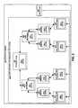
- FIG. 2is an example block diagram of a predictive model 150 predicting behavior of a configuration for a hierarchy of caches and a storage pool at a final level with respect to a workload according to embodiments herein.
- FIG. 3is a flowchart of an example of processing steps performed by the predictive model to predict a propagation of a workload throughout a configuration for a hierarchy of caches and a storage pool at the final level, and to provide a view of performance metrics and resource allocation metrics with respect to predicting a propagation of a workload throughout a configuration for a hierarchy of caches and a storage pool at the final level according to embodiments herein.
- FIG. 4is a flowchart of an example of processing steps performed by the predictive model to provide a concurrent view of performance metrics, resource allocation metrics, and recommendations with respect to predicting a propagation of a workload throughout multiple configurations for a hierarchy of caches and a storage pool at the final level according to embodiments herein.
- FIG. 5is a flowchart of an example of processing steps performed by the predictive model to define a workload to be applied to a hierarchy of caches and a storage pool at the final level according to embodiments herein.
- FIG. 6is an example view of a specified workload in the predictive model implemented via a spreadsheet application according to embodiments herein.
- FIG. 7is a flowchart of an example of processing steps performed by a predictive model to specify a configuration according to embodiments herein.
- FIG. 8is an example view of a defined configuration in a predictive model implemented via a spreadsheet application according to embodiments herein.
- FIG. 9is an example view of performance metrics computed by a predictive model implemented via a spreadsheet application according to embodiments herein.
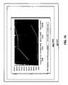
- FIG. 10is an example view of a graph computed by a predictive model based, in part, on performance metrics for each level in a configuration for a hierarchy of caches and storage pools at a final level according to embodiments herein.
- Embodiments of a predictive modeldefine a workload to be applied to a hierarchy of caches having multiple levels of caches and a storage pool at the final level.
- the predictive modeldefines a configuration for the hierarchy of caches by specifying cache characteristics of each level of the hierarchy of caches and the storage characteristics of the storage pool at the final level and applies the workload to the configuration.
- the predictive modelcomputes a performance metric based on a portion of the workload satisfied at the level and the cache characteristics or storage characteristics of the level.
- the predictive modelcomputes resource allocation metrics based on the performance metric for the levels and a cost associated with the configuration. Based on the workload, the configuration, performance metrics, and resource allocation metrics, the predictive model creates a design time recommendation for the hierarchy of caches and the storage pool at the final level, a configuration time recommendation for the hierarchy of caches and the storage pool at the final level, and a run time recommendation for the hierarchy of caches and the storage pool at the final level. It is understood that embodiments of predictive model, as discussed herein, are not limited to storage environment implementations regarding a Storage Area Network.
- the predictive modelcan be implemented via a spreadsheet application. Since the spreadsheet implements the predictive model, various selectable workloads and selectable configurations can be described in a list of parameters.
- the predictive modelcan predict input/output (I/O) performance characteristics associated with a workload of requests propagating through a hierarchy of caches and a storage pool at the final level configured according to a configuration. It is understood that a cache at a particular level in the hierarchy of caches can be (but is not limited to) a storage array cache, a server cache, an application cache, or a network cache. It is further understood that a storage pool is included as the final level in the hierarchy of caches.
- the predictive modelinstantly calculates I/O request analyses across the multiple levels of the hierarchy of caches and the storage pool at the final level, such as overall service times. For each level in a configuration for the hierarchy of caches and the storage pool at the final level, the predictive model calculates the percentages of I/O requests satisfied, the cumulative percentage of requests satisfied, and the maximum percentage of I/O operations per second (IOPS) capacity used.
- IOPSI/O operations per second
- the predictive modelcan be embedded in a self-managed storage system.
- An embedded predictive modelcan process data related to workloads experienced by the self-managed storage system and characteristics of caches and at least one storage pool in the self-managed system. As the embedded predictive model processes such data, the predictive model can compute performance metrics that can trigger: automated cache partitioning, allocation of cache resources in a grid or network, allocation of hierarchical cache resources to storage volumes, and a block virtualization policy engine to determine equivalent tiers of storage based on access patterns and fitness metrics (e.g. media cost, power consumption, etc.).
- fitness metricse.g. media cost, power consumption, etc.
- FIG. 1is an example block diagram illustrating an architecture of a computer system 110 that executes, runs, interprets, operates or otherwise performs a predictive model application 150 - 1 and/or predictive model process 150 - 2 (e.g. an executing version of a predictive model 150 as controlled or configured by user 108 ) according to embodiments herein.
- the computer system 110may be any type of computerized device such as a personal computer, a client computer system, workstation, portable computing device, console, laptop, network terminal, computing elements within a storage system, etc. This list is not exhaustive and is provided as an example of different possible embodiments.
- computer system 110can include any number of computer systems in a network environment to carry the embodiments as described herein.
- the computer system 110includes an interconnection mechanism 111 such as a data bus, motherboard or other circuitry that couples a memory system 112 , a processor 113 , an input/output interface 114 , and a display 130 . If so configured, the display can be used to present a graphical user interface of the predictive model 150 to user 108 .
- An input device 116e.g., one or more user/developer controlled devices such as a keyboard, mouse, touch pad, etc.
- the computer system 110can be a client system and/or a server system.
- the predictive model application 150 - 1 and/or the predictive model process 150 - 2can be distributed and executed in multiple nodes in a computer network environment or performed locally on a single computer.
- the processor 113accesses the memory system 112 via the interconnect 111 in order to launch, run, execute, interpret or otherwise perform the logic instructions of the predictive model application 150 - 1 .
- Execution of the predictive model application 150 - 1 in this mannerproduces the predictive model process 150 - 2 .
- the predictive model process 150 - 2represents one or more portions or runtime instances of the predictive model application 150 - 1 (or the entire application 150 - 1 ) performing or executing within or upon the processor 113 in the computerized device 110 at runtime.
- the predictive model application 150 - 1may be stored on a computer readable medium (such as a floppy disk), hard disk, electronic, magnetic, optical, or other computer readable medium. It is understood that embodiments and techniques discussed herein are well suited for other applications as well.
- the computer system 110may include other processes and/or software and hardware components, such as an operating system.
- Display 130need not be coupled directly to computer system 110 .
- the predictive model application 150 - 1can be executed on a remotely accessible computerized device via the communication interface 115 .
- FIG. 2is an example block diagram of a predictive model 150 predicting behavior of a configuration for a hierarchy of caches with respect to a workload according to embodiments herein.
- the predictive model 150defines a configuration for with a hierarchy of caches 204 in front of a storage pool 260 at a final level of the hierarchy of caches 204 , where the storage pool 260 can be a storage array(s), etc.
- the configuration for the hierarchy of caches 204includes four levels: an application level, a server level, a host network level and the storage pool 260 . It is understood that the configuration for the hierarchy of caches 204 is not limited to four levels.
- the application levelincludes applications 210 , 215 , 220 , 225 , each with their own respective caches 210 - 1 , 215 - 1 , 220 - 1 , 225 - 1 .
- the server levelincludes servers 230 , 235 , 240 , 245 , each with their own respective caches 230 - 1 , 235 - 1 , 240 - 1 , 245 - 1 .
- the host network levelincludes host networks 250 , 255 , each with their own respective caches 250 - 1 , 255 - 1 .
- the storage pool 260includes its own cache 260 - 1 as well.
- the predictive model 150specifies parameters in the configuration for the hierarchy of caches 204 to describe cache characteristics for each cache 210 - 1 , 215 - 1 , 220 - 1 , 225 - 1 , 230 - 1 , 235 - 1 , 240 - 1 , 245 - 1 , 250 - 1 , 255 - 1 , 260 - 1 at each level.
- the predictive model 150also specifies parameters in the configuration for the storage pool 260 .
- the predictive model 150also defines a workload 205 , which includes a set of Input/Output (I/O) operations. Based on parameters that describe the workload 205 and cache characteristics, the predictive model 150 predicts a propagation of the workload 205 from the application level to the storage pool 260 (e.g. individual disk drives in the storage array or other non-volatile storage medium).
- I/OInput/Output
- the predictive model 150predicts the propagation of the workload 205 across various levels, certain portions of the workload 205 will be satisfied at different levels in the hierarchy of caches. In other words, for each request, the cache at that level result in either a cache hit, returning the requested data item, or a cache miss, in which case the cache at the next level is searched. For example, the predictive model 150 can predict that a portion of the workload will not be satisfied until it reaches the storage array level. Hence, that portion of the workload 205 passes through, unsatisfied, the caches 210 - 1 , 230 - 1 , and 250 - 1 at the application level, server level and host network level respectively, until the cache 260 - 1 or the storage pool 260 satisfies that portion of the workload.
- the predictive model 150creates performance metrics that describe the predicted behavior of the cache 260 - 1 and the storage pool 260 —based on satisfying a given portion of the workload.
- the performance metricscan be used to create resource allocation metrics which take into consideration a cost of the cache 260 - 1 at the storage pool 260 and the work the cache 260 - 1 at the storage pool 260 performs to satisfy a portion of the workload. It is understood that that predictive model 150 creates performance metrics and resource allocations for each level based a portion of the workload that is predicted to be satisfied at that level.
- FIGS. 3 , 4 , 5 and 7illustrate various embodiments of the predictive model 150 .
- the rectangular elements in flowcharts 300 , 400 , 500 and 700denote “processing blocks” and represent computer software instructions or groups of instructions upon a computer readable medium. Additionally, the processing blocks represent steps performed by hardware such as a computer, digital signal processor circuit, application specific integrated circuit (ASIC), etc.
- ASICapplication specific integrated circuit
- Flowcharts 300 , 400 , 500 and 700do not necessarily depict the syntax of any particular programming language. Rather, flowcharts 300 , 400 , 500 and 700 illustrate the functional information one of ordinary skill in the art requires to fabricate circuits or to generate computer software to perform the processing required in accordance with the present invention.
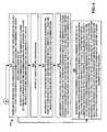
- FIG. 3is a flowchart 300 of an example of processing steps performed by the predictive model to predict a propagation of a workload throughout a configuration for a hierarchy of caches, and to provide a view of performance metrics and resource allocation metrics with respect to predicting a propagation of a workload throughout a configuration for a hierarchy of caches according to embodiments herein.
- the predictive model 150defines a workload to be applied to a hierarchy of caches, which includes a storage pool at a final level of the hierarchy of caches. (e.g. data repository(ies), database(s), memory pool(s), storage arrays(s), etc.).
- the hierarchy of cachesincludes multiple levels of caches. It is understood that the predictive model 150 can define various workloads comprising different combinations of sequential and random reads and writes. In addition, such workloads can be skewed, thereby possessing non-uniform access distributions to data in the hierarchy of caches and the storage pool at the final level.
- the predictive model 150defines a configuration for the hierarchy of caches that specifies cache characteristics of each level of the hierarchy of caches—and storage characteristics of the storage pool at the final level.
- the predictive model 150predicts a propagation of the workload throughout the configuration.
- the predictive model 150applies the workload to propagate from an initial level to a last level in the hierarchy of caches.
- portions of the workloadcan be satisfied by various levels rather than having requests access the slower memory pool.
- the predictive model 150satisfies a first portion of the workload at a first level of the hierarchy of caches.
- a second portioncan pass through the first level to eventually be satisfied at a deeper level of the hierarchy of caches. It is understood that some portions of the workload may not be satisfied at any levels of the hierarchy of caches and may be required to access the memory pool.
- the predictive model 150computes performance metrics based on a portion of the workload satisfied at the level and the cache characteristics of the level.
- the predictive model 150computes resource allocation metrics based on the at least one performance metric for at least one level and a cost associated with the configuration.
- a resource allocation metriccan reflect a relationship between a cost of a level of the hierarchy and a portion of the workload satisfied at that level.
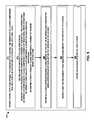
- FIG. 4is a flowchart 400 of an example of processing steps performed by the predictive model 150 to provide a concurrent view of performance metrics, resource allocation metrics, and recommendations with respect to predicting a propagation of a workload throughout multiple configurations for a hierarchy of caches according to embodiments herein.
- the predictive model 150creates recommendations, such as: design time recommendations, configuration time recommendations, and run time recommendations for the hierarchy of caches.
- the predictive model 150defines other configurations.
- the predictive model 150computes performance metrics, resource allocation metrics and creates recommendations.
- the predictive model 150provides a concurrent view of the performance metrics, the resource allocation metrics and recommendations in a user interface.
- the predictive model 150can identify a desirable level for storing a class of data potentially associated with a request in the set of I/O operations.
- the predictive modelcomputes performance metrics and resource allocation metrics to identify a desirable level within the hierarchy of caches and a storage pool(s) at the final level to initially cache data in a class—the class of data potentially associated with a request in the set of I/O operations.
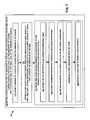
- FIG. 5is a flowchart 500 of an example of processing steps performed by the predictive model to define a workload to be applied to a hierarchy of caches according to embodiments herein.
- the workloadcan be defined according to parameters listed in a spreadsheet application.
- the predictive modeldefines a set of input/output (I/O) operations, including a first request class comprising a number of sequential read operations, a second request class comprising a number of sequential write operations, a third request class comprising a number of random read operations and a fourth request class comprising a number of random write operations.
- I/Oinput/output
- the predictive model 150defines an access skew describing a percentage of the set of I/O operations associated with a percentage of data within the hierarchy of caches. It is understood that an access skew represents that a larger percentage of the requests in the set of I/O operations access a smaller percentage of the available data—thereby creating a non-uniform data access distribution since other data will not be repeatedly accessed by requests in the set of I/O operations. Further, at steps 530 and 540 , the predictive model 150 defines a size of the memory pool size included behind the hierarchy of caches and defines an average sequential read count (such as an average sequential read count for cacheable units of data), respectively. It is understood that the workload is not limited to being described by the parameters of steps 510 - 540 .
- FIG. 6is an example view of a defined workload in the predictive model 150 implemented via a spreadsheet application according to embodiments herein.
- the predictive model 150provides for the view 160 - 1 via a graphical user interface 160 (G.U.I.) of the spreadsheet application.
- G.U.I.graphical user interface 160
- the listing of workload parameters for a workload labeled “TPC-H”consists of a set of I/O operations where 45% of the I/O operations are sequential reads, 15% are random reads, 40% are sequential writes, and 0% random writes.
- “A-skew” parametersrelate to percentages of the total number of sequential and random I/O operations that will interact with a subset of the data
- the “B-skew” parametersrelate to the percentage of records that store that data. As an example of skewed access for a particular class of operations, 80% of the accesses may be to 20% of the data; then A-skew is 80% and B-skew is 20%.
- FIG. 7is a flowchart of an example of processing steps performed by a predictive model 150 to define a configuration according to embodiments herein.
- the predictive model 150defines a number of levels of caches for the hierarchy of caches.
- the predictive model 150defines an exclusivity characteristic indicating whether data must reside at only one level or whether double caching of data is expected to occur across at least two levels in the hierarchy of caches.
- double cachingcan refer to the fact that an effective size of an intermediate cache in the hierarchy of caches is reduced since some of its pages (e.g. the most-referenced ones) are likely to be cached at a next shallower level towards the application.
- the caches in the hierarchycan operate independently, thus double caching happens naturally, and each particular request attempts to hit at each succeeding deeper level before accessing the pool of storage 270 behind the hierarchy of caches, which can be thought of as a cache level with all data items, thus having a 100% hit rate.
- the predictive model 150defines the cache characteristics of each level of the hierarchy of caches and the storage pool.
- the predictive model 150defines a set of input/output (I/O) operation response times for each level.
- the predictive model 150defines a maximum throughput associated with read operations for each level.
- the predictive model 150defines a maximum throughput associated with write operations for each level.
- the predictive model 150defines a cost associated with each level.
- the predictive model 150defines at least one efficiency characteristic
- FIG. 8is an example view of a defined configuration in a predictive model 150 implemented via a spreadsheet application according to embodiments herein.
- the predictive model 150provides for a view 160 - 2 of the defined configuration via a graphical user interface 160 (G.U.I.) of the spreadsheet application.
- the configuration defined via the spreadsheet applicationcovers a configuration for a hierarchy having four levels: a server level, network level, array level and a storage pool level.
- the predictive model 150provides parameters that describe cache or storage characteristics, such as: I/O response time for read and write operations, and a cost associated with each cache level. It is understood that the view 160 - 1 illustrated in FIG. 6 can be concurrently displayed with the view 160 - 2 displaying the configuration parameters.
- FIG. 9is an example view of performance metrics computed by a predictive model 150 implemented via a spreadsheet application according to embodiments herein.
- the predictive model 150provides for a view 160 - 3 of the performance metrics via a graphical user interface 160 (G.U.I.) of the spreadsheet application.
- the predictive model 150lists performance metrics for each cache level in a configuration for the hierarchy of caches.
- the predictive model 150also provides performance metrics for the storage pool at the final level of the hierarchy of caches. It is understood that the views 160 - 1 , 160 - 2 illustrated in FIGS. 6 and 8 can be concurrently displayed with the view 160 - 3 displaying the performance metrics.
- FIG. 10is an example view of a graph computed by a predictive model 150 based, in part, on performance metrics for each level in a configuration for a hierarchy of caches according to embodiments herein.
- the predictive model 150provides for a view 160 - 4 of the graph via a graphical user interface 160 (G.U.I.) of the spreadsheet application. It is understood that the views 160 - 1 , 160 - 2 , 160 - 3 illustrated in FIGS. 6 , 8 and 9 can be concurrently displayed with the view 160 - 4 displaying the graph.
- G.U.I.graphical user interface
- a multi-level caching systemcan be a hierarchy of caches including some combination of a storage array cache, network cache, application cache, server cache and a database management system cache.
- the predictive modelallows for various workloads and database sizes to be represented via parameters (including I/O request profiles and skews) and allows for various configurations to be represented via parameters as well (including performance and cost).
- the predictive model 150can be implemented for predicting behavior of workloads on configurations of any type of storage environment, including but not limited to hierarchies of storage pools.
- the methods and systems described hereinare not limited to a particular hardware or software configuration, and may find applicability in many computing or processing environments.
- the methods and systemsmay be implemented in hardware or software, or a combination of hardware and software.
- the methods and systemsmay be implemented in one or more computer programs, where a computer program may be understood to include one or more processor executable instructions.
- the computer program(s)may execute on one or more programmable processors, and may be stored on one or more storage medium readable by the processor (including volatile and non-volatile memory and/or storage elements), one or more input devices, and/or one or more output devices.
- the processorthus may access one or more input devices to obtain input data, and may access one or more output devices to communicate output data.
- the input and/or output devicesmay include one or more of the following: Random Access Memory (RAM), Redundant Array of Independent Disks (RAID), floppy drive, CD, DVD, magnetic disk, internal hard drive, external hard drive, memory stick, or other storage device capable of being accessed by a processor as provided herein, where such aforementioned examples are not exhaustive, and are for illustration and not limitation.
- RAMRandom Access Memory
- RAIDRedundant Array of Independent Disks
- floppy driveCD, DVD, magnetic disk, internal hard drive, external hard drive, memory stick, or other storage device capable of being accessed by a processor as provided herein, where such aforementioned examples are not exhaustive, and are for illustration and not limitation.
- the computer program(s)may be implemented using one or more high level procedural or object-oriented programming languages to communicate with a computer system; however, the program(s) may be implemented in assembly or machine language, if desired.
- the languagemay be compiled or interpreted.
- the processor(s)may thus be embedded in one or more devices that may be operated independently or together in a networked environment, where the network may include, for example, a Local Area Network (LAN), wide area network (WAN), and/or may include an intranet and/or the internet and/or another network.
- the network(s)may be wired or wireless or a combination thereof and may use one or more communications protocols to facilitate communications between the different processors.
- the processorsmay be configured for distributed processing and may utilize, in some embodiments, a client-server model as needed. Accordingly, the methods and systems may utilize multiple processors and/or processor devices, and the processor instructions may be divided amongst such single- or multiple-processor/devices.
- the device(s) or computer systems that integrate with the processor(s)may include, for example, a personal computer(s), workstation(s) (e.g., Sun, HP), personal digital assistant(s) (PDA(s)), handheld device(s) such as cellular telephone(s), laptop(s), handheld computer(s), or another device(s) capable of being integrated with a processor(s) that may operate as provided herein. Accordingly, the devices provided herein are not exhaustive and are provided for illustration and not limitation.
- references to “a microprocessor” and “a processor”, or “the microprocessor” and “the processor,”may be understood to include one or more microprocessors that may communicate in a stand-alone and/or a distributed environment(s), and may thus be configured to communicate via wired or wireless communications with other processors, where such one or more processor may be configured to operate on one or more processor-controlled devices that may be similar or different devices.
- Use of such “microprocessor” or “processor” terminologymay thus also be understood to include a central processing unit, an arithmetic logic unit, an application-specific integrated circuit (IC), and/or a task engine, with such examples provided for illustration and not limitation.
- references to memorymay include one or more processor-readable and accessible memory elements and/or components that may be internal to the processor-controlled device, external to the processor-controlled device, and/or may be accessed via a wired or wireless network using a variety of communications protocols, and unless otherwise specified, may be arranged to include a combination of external and internal memory devices, where such memory may be contiguous and/or partitioned based on the application.
- references to a databasemay be understood to include one or more memory associations, where such references may include commercially available database products (e.g., SQL, Informix, Oracle) and also proprietary databases, and may also include other structures for associating memory such as links, queues, graphs, trees, with such structures provided for illustration and not limitation.
- references to a networkmay include one or more intranets and/or the internet.
- References herein to microprocessor instructions or microprocessor-executable instructions, in accordance with the above,may be understood to include programmable hardware.
Landscapes
- Engineering & Computer Science (AREA)
- Theoretical Computer Science (AREA)
- General Engineering & Computer Science (AREA)
- General Physics & Mathematics (AREA)
- Physics & Mathematics (AREA)
- Evolutionary Biology (AREA)
- Computer Hardware Design (AREA)
- Bioinformatics & Computational Biology (AREA)
- Quality & Reliability (AREA)
- Life Sciences & Earth Sciences (AREA)
- Bioinformatics & Cheminformatics (AREA)
- Computer Networks & Wireless Communication (AREA)
- Signal Processing (AREA)
- Memory System Of A Hierarchy Structure (AREA)
Abstract
Description
Claims (20)
Priority Applications (2)
| Application Number | Priority Date | Filing Date | Title |
|---|---|---|---|
| US12/190,071US8112586B1 (en) | 2008-06-13 | 2008-08-12 | Predicting and optimizing I/O performance characteristics in a multi-level caching system |
| US13/349,224US8489816B1 (en) | 2008-06-13 | 2012-01-12 | Predicting and optimizing I/O performance characteristics in a multi-level caching system |
Applications Claiming Priority (2)
| Application Number | Priority Date | Filing Date | Title |
|---|---|---|---|
| US13916008A | 2008-06-13 | 2008-06-13 | |
| US12/190,071US8112586B1 (en) | 2008-06-13 | 2008-08-12 | Predicting and optimizing I/O performance characteristics in a multi-level caching system |
Related Parent Applications (1)
| Application Number | Title | Priority Date | Filing Date |
|---|---|---|---|
| US13916008AContinuation | 2008-06-13 | 2008-06-13 |
Related Child Applications (1)
| Application Number | Title | Priority Date | Filing Date |
|---|---|---|---|
| US13/349,224ContinuationUS8489816B1 (en) | 2008-06-13 | 2012-01-12 | Predicting and optimizing I/O performance characteristics in a multi-level caching system |
Publications (1)
| Publication Number | Publication Date |
|---|---|
| US8112586B1true US8112586B1 (en) | 2012-02-07 |
Family
ID=45532317
Family Applications (2)
| Application Number | Title | Priority Date | Filing Date |
|---|---|---|---|
| US12/190,071Active2030-05-04US8112586B1 (en) | 2008-06-13 | 2008-08-12 | Predicting and optimizing I/O performance characteristics in a multi-level caching system |
| US13/349,224ActiveUS8489816B1 (en) | 2008-06-13 | 2012-01-12 | Predicting and optimizing I/O performance characteristics in a multi-level caching system |
Family Applications After (1)
| Application Number | Title | Priority Date | Filing Date |
|---|---|---|---|
| US13/349,224ActiveUS8489816B1 (en) | 2008-06-13 | 2012-01-12 | Predicting and optimizing I/O performance characteristics in a multi-level caching system |
Country Status (1)
| Country | Link |
|---|---|
| US (2) | US8112586B1 (en) |
Cited By (18)
| Publication number | Priority date | Publication date | Assignee | Title |
|---|---|---|---|---|
| US20130318305A1 (en)* | 2010-11-11 | 2013-11-28 | International Business Machines Corporation | Method and Apparatus for Optimal Cache Sizing and Configuration for Large Memory Systems |
| US20140207944A1 (en)* | 2013-01-24 | 2014-07-24 | Hitachi, Ltd. | Method and system for managing cloud computing environment |
| US8924328B1 (en) | 2012-06-29 | 2014-12-30 | Emc Corporation | Predictive models for configuration management of data storage systems |
| US9092508B1 (en) | 2013-02-15 | 2015-07-28 | Emc Corporation | Overseeing data storage equipment power usage via local collection of power consumption data and remote evaluation and reporting of performance |
| US20160124652A1 (en)* | 2014-11-05 | 2016-05-05 | Nimble Storage, Inc. | Methods and Systems for Determining Hardware Sizing for Storage Array Systems |
| WO2017058045A1 (en)* | 2015-09-29 | 2017-04-06 | Emc Corporation | Dynamic storage tiering based on predicted workloads |
| US20170308300A1 (en)* | 2016-04-25 | 2017-10-26 | Samsung Electronics Co., Ltd. | Methods of operating mobile devices and mobile devices |
| US20170322725A1 (en)* | 2016-05-03 | 2017-11-09 | International Business Machines Corporation | Estimating file level input/output operations per second (iops) |
| US9983795B1 (en)* | 2015-03-31 | 2018-05-29 | EMC IP Holding Company LLC | Techniques for determining a storage configuration |
| US20180167446A1 (en)* | 2016-04-22 | 2018-06-14 | Google Inc. | Response latency reduction in fixed allocation content selection infrastructure |
| US10339455B1 (en)* | 2014-03-24 | 2019-07-02 | EMC IP Holding Company LLC | Techniques for determining workload skew |
| US10853139B2 (en)* | 2018-10-19 | 2020-12-01 | EMC IP Holding Company LLC | Dynamic workload management based on predictive modeling and recommendation engine for storage systems |
| US10956048B2 (en)* | 2017-11-21 | 2021-03-23 | Distech Controls Inc. | Computing device and method for inferring a predicted number of physical blocks erased from a flash memory |
| US11037056B2 (en) | 2017-11-21 | 2021-06-15 | Distech Controls Inc. | Computing device and method for inferring a predicted number of data chunks writable on a flash memory before wear out |
| WO2022061727A1 (en)* | 2020-09-25 | 2022-03-31 | Alibaba Group Holding Limited | Method and apparatus for cache management |
| US11625327B2 (en)* | 2019-12-10 | 2023-04-11 | EMC IP Holding Company LLC | Cache memory management |
| US11868613B1 (en)* | 2021-01-15 | 2024-01-09 | Change Healthcare Holdings Llc | Selection of health care data storage policy based on historical data storage patterns and/or patient characteristics using an artificial intelligence engine |
| CN119292962A (en)* | 2022-03-02 | 2025-01-10 | 华为技术有限公司 | Shared cache management method, device and storage medium |
Families Citing this family (6)
| Publication number | Priority date | Publication date | Assignee | Title |
|---|---|---|---|---|
| US10466936B2 (en)* | 2014-09-26 | 2019-11-05 | Oracle International Corporation | Scalable, multi-dimensional search for optimal configuration |
| US9836407B2 (en) | 2014-10-23 | 2017-12-05 | Netapp, Inc. | Method for using service level objectives to dynamically allocate cache resources among competing workloads |
| US10089236B2 (en)* | 2015-07-13 | 2018-10-02 | Sios Technology Corporation | Apparatus and method of performing agentless remote IO catching analysis, prediction, automation, and recommendation in a computer environment |
| US10162835B2 (en)* | 2015-12-15 | 2018-12-25 | Pure Storage, Inc. | Proactive management of a plurality of storage arrays in a multi-array system |
| CN110166553A (en)* | 2019-05-22 | 2019-08-23 | 苏州浪潮智能科技有限公司 | A kind of data access method, device, equipment and readable storage medium storing program for executing |
| US11526446B1 (en) | 2020-05-22 | 2022-12-13 | Amazon Technologies, Inc. | Modifying caching amongst services from a history of requests and responses |
Citations (1)
| Publication number | Priority date | Publication date | Assignee | Title |
|---|---|---|---|---|
| US20050071596A1 (en)* | 2003-09-26 | 2005-03-31 | International Business Machines Corporation | Method, apparatus and program storage device for providing automatic performance optimization of virtualized storage allocation within a network of storage elements |
Family Cites Families (1)
| Publication number | Priority date | Publication date | Assignee | Title |
|---|---|---|---|---|
| US20100036805A1 (en)* | 2008-08-05 | 2010-02-11 | International Business Machines Corporation | System Maintainable and Reusable I/O Value Caches |
- 2008
- 2008-08-12USUS12/190,071patent/US8112586B1/enactiveActive
- 2012
- 2012-01-12USUS13/349,224patent/US8489816B1/enactiveActive
Patent Citations (1)
| Publication number | Priority date | Publication date | Assignee | Title |
|---|---|---|---|---|
| US20050071596A1 (en)* | 2003-09-26 | 2005-03-31 | International Business Machines Corporation | Method, apparatus and program storage device for providing automatic performance optimization of virtualized storage allocation within a network of storage elements |
Cited By (27)
| Publication number | Priority date | Publication date | Assignee | Title |
|---|---|---|---|---|
| US20130318305A1 (en)* | 2010-11-11 | 2013-11-28 | International Business Machines Corporation | Method and Apparatus for Optimal Cache Sizing and Configuration for Large Memory Systems |
| US9229877B2 (en)* | 2010-11-11 | 2016-01-05 | International Business Machines Corporation | Method and apparatus for optimal cache sizing and configuration for large memory systems |
| US8924328B1 (en) | 2012-06-29 | 2014-12-30 | Emc Corporation | Predictive models for configuration management of data storage systems |
| US20140207944A1 (en)* | 2013-01-24 | 2014-07-24 | Hitachi, Ltd. | Method and system for managing cloud computing environment |
| US9608933B2 (en)* | 2013-01-24 | 2017-03-28 | Hitachi, Ltd. | Method and system for managing cloud computing environment |
| US9092508B1 (en) | 2013-02-15 | 2015-07-28 | Emc Corporation | Overseeing data storage equipment power usage via local collection of power consumption data and remote evaluation and reporting of performance |
| US10339455B1 (en)* | 2014-03-24 | 2019-07-02 | EMC IP Holding Company LLC | Techniques for determining workload skew |
| US10956391B2 (en) | 2014-11-05 | 2021-03-23 | Hewlett Packard Enterprise Development Lp | Methods and systems for determining hardware sizing for storage array systems |
| US10235399B2 (en)* | 2014-11-05 | 2019-03-19 | Hewlett Packard Enterprise Development Lp | Methods and systems for determining hardware sizing for storage array systems |
| US20160124652A1 (en)* | 2014-11-05 | 2016-05-05 | Nimble Storage, Inc. | Methods and Systems for Determining Hardware Sizing for Storage Array Systems |
| US9983795B1 (en)* | 2015-03-31 | 2018-05-29 | EMC IP Holding Company LLC | Techniques for determining a storage configuration |
| WO2017058045A1 (en)* | 2015-09-29 | 2017-04-06 | Emc Corporation | Dynamic storage tiering based on predicted workloads |
| US10146469B2 (en) | 2015-09-29 | 2018-12-04 | EMC IP Holding Company, LLC | Dynamic storage tiering based on predicted workloads |
| US20180167446A1 (en)* | 2016-04-22 | 2018-06-14 | Google Inc. | Response latency reduction in fixed allocation content selection infrastructure |
| US10084854B2 (en)* | 2016-04-22 | 2018-09-25 | Google Llc | Response latency reduction in fixed allocation content selection infrastructure |
| US20170308300A1 (en)* | 2016-04-25 | 2017-10-26 | Samsung Electronics Co., Ltd. | Methods of operating mobile devices and mobile devices |
| US10416893B2 (en)* | 2016-04-25 | 2019-09-17 | Samsung Electronics Co., Ltd. | Methods of operating mobile devices and mobile devices |
| US10032115B2 (en)* | 2016-05-03 | 2018-07-24 | International Business Machines Corporation | Estimating file level input/output operations per second (IOPS) |
| US20170322725A1 (en)* | 2016-05-03 | 2017-11-09 | International Business Machines Corporation | Estimating file level input/output operations per second (iops) |
| US10956048B2 (en)* | 2017-11-21 | 2021-03-23 | Distech Controls Inc. | Computing device and method for inferring a predicted number of physical blocks erased from a flash memory |
| US11037056B2 (en) | 2017-11-21 | 2021-06-15 | Distech Controls Inc. | Computing device and method for inferring a predicted number of data chunks writable on a flash memory before wear out |
| US10853139B2 (en)* | 2018-10-19 | 2020-12-01 | EMC IP Holding Company LLC | Dynamic workload management based on predictive modeling and recommendation engine for storage systems |
| US11625327B2 (en)* | 2019-12-10 | 2023-04-11 | EMC IP Holding Company LLC | Cache memory management |
| WO2022061727A1 (en)* | 2020-09-25 | 2022-03-31 | Alibaba Group Holding Limited | Method and apparatus for cache management |
| US11868613B1 (en)* | 2021-01-15 | 2024-01-09 | Change Healthcare Holdings Llc | Selection of health care data storage policy based on historical data storage patterns and/or patient characteristics using an artificial intelligence engine |
| CN119292962A (en)* | 2022-03-02 | 2025-01-10 | 华为技术有限公司 | Shared cache management method, device and storage medium |
| CN119292962B (en)* | 2022-03-02 | 2025-07-15 | 华为技术有限公司 | Shared cache management method, device and storage medium |
Also Published As
| Publication number | Publication date |
|---|---|
| US8489816B1 (en) | 2013-07-16 |
Similar Documents
| Publication | Publication Date | Title |
|---|---|---|
| US8112586B1 (en) | Predicting and optimizing I/O performance characteristics in a multi-level caching system | |
| JP6639420B2 (en) | Method for flash-optimized data layout, apparatus for flash-optimized storage, and computer program | |
| US8601216B2 (en) | Method and system for removing cache blocks | |
| US11055224B2 (en) | Data processing apparatus and prefetch method | |
| US9128844B2 (en) | Enhancing analytics performance using distributed multi-tiering | |
| Oly et al. | Markov model prediction of I/O requests for scientific applications | |
| US11010379B2 (en) | Increasing performance of in-memory databases using re-ordered query execution plans | |
| Su et al. | In-situ bitmaps generation and efficient data analysis based on bitmaps | |
| Li et al. | Mining block correlations to improve storage performance | |
| Li et al. | SCALLA: A platform for scalable one-pass analytics using MapReduce | |
| Zhou et al. | Doppio: I/o-aware performance analysis, modeling and optimization for in-memory computing framework | |
| Akgun et al. | Improving storage systems using machine learning | |
| Zhang et al. | Making sense of performance in in-memory computing frameworks for scientific data analysis: A case study of the spark system | |
| Mutlu | Intelligent architectures for intelligent machines | |
| Ebrahimi et al. | RC-RNN: Reconfigurable cache architecture for storage systems using recurrent neural networks | |
| Huang et al. | Density-optimized intersection-free mapping and matrix multiplication for join-project operations | |
| US7685368B1 (en) | Methods and apparatus for removing data from a cache | |
| Sun et al. | Hyperion: Optimizing ssd access is all you need to enable cost-efficient out-of-core gnn training | |
| JP7730236B2 (en) | Computer system, computer program, and computer-implemented method (workload-driven database reorganization) | |
| Awasthi et al. | System-level characterization of datacenter applications | |
| US10067678B1 (en) | Probabilistic eviction of partial aggregation results from constrained results storage | |
| Ignacio et al. | Warmcache: A comprehensive distributed storage system combining replication, erasure codes and buffer cache | |
| Heo et al. | Boss: Bandwidth-optimized search accelerator for storage-class memory | |
| Yun et al. | Access pattern-based high-performance main memory system for graph processing on single machines | |
| Sun et al. | Hyperion: Co-Optimizing SSD Access and GPU Computation for Cost-Efficient GNN Training |
Legal Events
| Date | Code | Title | Description |
|---|---|---|---|
| AS | Assignment | Owner name:EMC CORPORATION, MASSACHUSETTS Free format text:ASSIGNMENT OF ASSIGNORS INTEREST;ASSIGNORS:REINER, DAVID;CARDENTE, JOHN;REEL/FRAME:026701/0574 Effective date:20110802 | |
| STCF | Information on status: patent grant | Free format text:PATENTED CASE | |
| FPAY | Fee payment | Year of fee payment:4 | |
| AS | Assignment | Owner name:CREDIT SUISSE AG, CAYMAN ISLANDS BRANCH, AS COLLATERAL AGENT, NORTH CAROLINA Free format text:SECURITY AGREEMENT;ASSIGNORS:ASAP SOFTWARE EXPRESS, INC.;AVENTAIL LLC;CREDANT TECHNOLOGIES, INC.;AND OTHERS;REEL/FRAME:040134/0001 Effective date:20160907 Owner name:THE BANK OF NEW YORK MELLON TRUST COMPANY, N.A., AS NOTES COLLATERAL AGENT, TEXAS Free format text:SECURITY AGREEMENT;ASSIGNORS:ASAP SOFTWARE EXPRESS, INC.;AVENTAIL LLC;CREDANT TECHNOLOGIES, INC.;AND OTHERS;REEL/FRAME:040136/0001 Effective date:20160907 Owner name:CREDIT SUISSE AG, CAYMAN ISLANDS BRANCH, AS COLLAT Free format text:SECURITY AGREEMENT;ASSIGNORS:ASAP SOFTWARE EXPRESS, INC.;AVENTAIL LLC;CREDANT TECHNOLOGIES, INC.;AND OTHERS;REEL/FRAME:040134/0001 Effective date:20160907 Owner name:THE BANK OF NEW YORK MELLON TRUST COMPANY, N.A., A Free format text:SECURITY AGREEMENT;ASSIGNORS:ASAP SOFTWARE EXPRESS, INC.;AVENTAIL LLC;CREDANT TECHNOLOGIES, INC.;AND OTHERS;REEL/FRAME:040136/0001 Effective date:20160907 | |
| AS | Assignment | Owner name:EMC IP HOLDING COMPANY LLC, MASSACHUSETTS Free format text:ASSIGNMENT OF ASSIGNORS INTEREST;ASSIGNOR:EMC CORPORATION;REEL/FRAME:040203/0001 Effective date:20160906 | |
| AS | Assignment | Owner name:THE BANK OF NEW YORK MELLON TRUST COMPANY, N.A., T Free format text:SECURITY AGREEMENT;ASSIGNORS:CREDANT TECHNOLOGIES, INC.;DELL INTERNATIONAL L.L.C.;DELL MARKETING L.P.;AND OTHERS;REEL/FRAME:049452/0223 Effective date:20190320 Owner name:THE BANK OF NEW YORK MELLON TRUST COMPANY, N.A., TEXAS Free format text:SECURITY AGREEMENT;ASSIGNORS:CREDANT TECHNOLOGIES, INC.;DELL INTERNATIONAL L.L.C.;DELL MARKETING L.P.;AND OTHERS;REEL/FRAME:049452/0223 Effective date:20190320 | |
| MAFP | Maintenance fee payment | Free format text:PAYMENT OF MAINTENANCE FEE, 8TH YEAR, LARGE ENTITY (ORIGINAL EVENT CODE: M1552); ENTITY STATUS OF PATENT OWNER: LARGE ENTITY Year of fee payment:8 | |
| AS | Assignment | Owner name:THE BANK OF NEW YORK MELLON TRUST COMPANY, N.A., TEXAS Free format text:SECURITY AGREEMENT;ASSIGNORS:CREDANT TECHNOLOGIES INC.;DELL INTERNATIONAL L.L.C.;DELL MARKETING L.P.;AND OTHERS;REEL/FRAME:053546/0001 Effective date:20200409 | |
| AS | Assignment | Owner name:WYSE TECHNOLOGY L.L.C., CALIFORNIA Free format text:RELEASE BY SECURED PARTY;ASSIGNOR:CREDIT SUISSE AG, CAYMAN ISLANDS BRANCH;REEL/FRAME:058216/0001 Effective date:20211101 Owner name:SCALEIO LLC, MASSACHUSETTS Free format text:RELEASE BY SECURED PARTY;ASSIGNOR:CREDIT SUISSE AG, CAYMAN ISLANDS BRANCH;REEL/FRAME:058216/0001 Effective date:20211101 Owner name:MOZY, INC., WASHINGTON Free format text:RELEASE BY SECURED PARTY;ASSIGNOR:CREDIT SUISSE AG, CAYMAN ISLANDS BRANCH;REEL/FRAME:058216/0001 Effective date:20211101 Owner name:MAGINATICS LLC, CALIFORNIA Free format text:RELEASE BY SECURED PARTY;ASSIGNOR:CREDIT SUISSE AG, CAYMAN ISLANDS BRANCH;REEL/FRAME:058216/0001 Effective date:20211101 Owner name:FORCE10 NETWORKS, INC., CALIFORNIA Free format text:RELEASE BY SECURED PARTY;ASSIGNOR:CREDIT SUISSE AG, CAYMAN ISLANDS BRANCH;REEL/FRAME:058216/0001 Effective date:20211101 Owner name:EMC IP HOLDING COMPANY LLC, TEXAS Free format text:RELEASE BY SECURED PARTY;ASSIGNOR:CREDIT SUISSE AG, CAYMAN ISLANDS BRANCH;REEL/FRAME:058216/0001 Effective date:20211101 Owner name:EMC CORPORATION, MASSACHUSETTS Free format text:RELEASE BY SECURED PARTY;ASSIGNOR:CREDIT SUISSE AG, CAYMAN ISLANDS BRANCH;REEL/FRAME:058216/0001 Effective date:20211101 Owner name:DELL SYSTEMS CORPORATION, TEXAS Free format text:RELEASE BY SECURED PARTY;ASSIGNOR:CREDIT SUISSE AG, CAYMAN ISLANDS BRANCH;REEL/FRAME:058216/0001 Effective date:20211101 Owner name:DELL SOFTWARE INC., CALIFORNIA Free format text:RELEASE BY SECURED PARTY;ASSIGNOR:CREDIT SUISSE AG, CAYMAN ISLANDS BRANCH;REEL/FRAME:058216/0001 Effective date:20211101 Owner name:DELL PRODUCTS L.P., TEXAS Free format text:RELEASE BY SECURED PARTY;ASSIGNOR:CREDIT SUISSE AG, CAYMAN ISLANDS BRANCH;REEL/FRAME:058216/0001 Effective date:20211101 Owner name:DELL MARKETING L.P., TEXAS Free format text:RELEASE BY SECURED PARTY;ASSIGNOR:CREDIT SUISSE AG, CAYMAN ISLANDS BRANCH;REEL/FRAME:058216/0001 Effective date:20211101 Owner name:DELL INTERNATIONAL, L.L.C., TEXAS Free format text:RELEASE BY SECURED PARTY;ASSIGNOR:CREDIT SUISSE AG, CAYMAN ISLANDS BRANCH;REEL/FRAME:058216/0001 Effective date:20211101 Owner name:DELL USA L.P., TEXAS Free format text:RELEASE BY SECURED PARTY;ASSIGNOR:CREDIT SUISSE AG, CAYMAN ISLANDS BRANCH;REEL/FRAME:058216/0001 Effective date:20211101 Owner name:CREDANT TECHNOLOGIES, INC., TEXAS Free format text:RELEASE BY SECURED PARTY;ASSIGNOR:CREDIT SUISSE AG, CAYMAN ISLANDS BRANCH;REEL/FRAME:058216/0001 Effective date:20211101 Owner name:AVENTAIL LLC, CALIFORNIA Free format text:RELEASE BY SECURED PARTY;ASSIGNOR:CREDIT SUISSE AG, CAYMAN ISLANDS BRANCH;REEL/FRAME:058216/0001 Effective date:20211101 Owner name:ASAP SOFTWARE EXPRESS, INC., ILLINOIS Free format text:RELEASE BY SECURED PARTY;ASSIGNOR:CREDIT SUISSE AG, CAYMAN ISLANDS BRANCH;REEL/FRAME:058216/0001 Effective date:20211101 | |
| AS | Assignment | Owner name:SCALEIO LLC, MASSACHUSETTS Free format text:RELEASE OF SECURITY INTEREST IN PATENTS PREVIOUSLY RECORDED AT REEL/FRAME (040136/0001);ASSIGNOR:THE BANK OF NEW YORK MELLON TRUST COMPANY, N.A., AS NOTES COLLATERAL AGENT;REEL/FRAME:061324/0001 Effective date:20220329 Owner name:EMC IP HOLDING COMPANY LLC (ON BEHALF OF ITSELF AND AS SUCCESSOR-IN-INTEREST TO MOZY, INC.), TEXAS Free format text:RELEASE OF SECURITY INTEREST IN PATENTS PREVIOUSLY RECORDED AT REEL/FRAME (040136/0001);ASSIGNOR:THE BANK OF NEW YORK MELLON TRUST COMPANY, N.A., AS NOTES COLLATERAL AGENT;REEL/FRAME:061324/0001 Effective date:20220329 Owner name:EMC CORPORATION (ON BEHALF OF ITSELF AND AS SUCCESSOR-IN-INTEREST TO MAGINATICS LLC), MASSACHUSETTS Free format text:RELEASE OF SECURITY INTEREST IN PATENTS PREVIOUSLY RECORDED AT REEL/FRAME (040136/0001);ASSIGNOR:THE BANK OF NEW YORK MELLON TRUST COMPANY, N.A., AS NOTES COLLATERAL AGENT;REEL/FRAME:061324/0001 Effective date:20220329 Owner name:DELL MARKETING CORPORATION (SUCCESSOR-IN-INTEREST TO FORCE10 NETWORKS, INC. AND WYSE TECHNOLOGY L.L.C.), TEXAS Free format text:RELEASE OF SECURITY INTEREST IN PATENTS PREVIOUSLY RECORDED AT REEL/FRAME (040136/0001);ASSIGNOR:THE BANK OF NEW YORK MELLON TRUST COMPANY, N.A., AS NOTES COLLATERAL AGENT;REEL/FRAME:061324/0001 Effective date:20220329 Owner name:DELL PRODUCTS L.P., TEXAS Free format text:RELEASE OF SECURITY INTEREST IN PATENTS PREVIOUSLY RECORDED AT REEL/FRAME (040136/0001);ASSIGNOR:THE BANK OF NEW YORK MELLON TRUST COMPANY, N.A., AS NOTES COLLATERAL AGENT;REEL/FRAME:061324/0001 Effective date:20220329 Owner name:DELL INTERNATIONAL L.L.C., TEXAS Free format text:RELEASE OF SECURITY INTEREST IN PATENTS PREVIOUSLY RECORDED AT REEL/FRAME (040136/0001);ASSIGNOR:THE BANK OF NEW YORK MELLON TRUST COMPANY, N.A., AS NOTES COLLATERAL AGENT;REEL/FRAME:061324/0001 Effective date:20220329 Owner name:DELL USA L.P., TEXAS Free format text:RELEASE OF SECURITY INTEREST IN PATENTS PREVIOUSLY RECORDED AT REEL/FRAME (040136/0001);ASSIGNOR:THE BANK OF NEW YORK MELLON TRUST COMPANY, N.A., AS NOTES COLLATERAL AGENT;REEL/FRAME:061324/0001 Effective date:20220329 Owner name:DELL MARKETING L.P. (ON BEHALF OF ITSELF AND AS SUCCESSOR-IN-INTEREST TO CREDANT TECHNOLOGIES, INC.), TEXAS Free format text:RELEASE OF SECURITY INTEREST IN PATENTS PREVIOUSLY RECORDED AT REEL/FRAME (040136/0001);ASSIGNOR:THE BANK OF NEW YORK MELLON TRUST COMPANY, N.A., AS NOTES COLLATERAL AGENT;REEL/FRAME:061324/0001 Effective date:20220329 Owner name:DELL MARKETING CORPORATION (SUCCESSOR-IN-INTEREST TO ASAP SOFTWARE EXPRESS, INC.), TEXAS Free format text:RELEASE OF SECURITY INTEREST IN PATENTS PREVIOUSLY RECORDED AT REEL/FRAME (040136/0001);ASSIGNOR:THE BANK OF NEW YORK MELLON TRUST COMPANY, N.A., AS NOTES COLLATERAL AGENT;REEL/FRAME:061324/0001 Effective date:20220329 | |
| AS | Assignment | Owner name:SCALEIO LLC, MASSACHUSETTS Free format text:RELEASE OF SECURITY INTEREST IN PATENTS PREVIOUSLY RECORDED AT REEL/FRAME (045455/0001);ASSIGNOR:THE BANK OF NEW YORK MELLON TRUST COMPANY, N.A., AS NOTES COLLATERAL AGENT;REEL/FRAME:061753/0001 Effective date:20220329 Owner name:EMC IP HOLDING COMPANY LLC (ON BEHALF OF ITSELF AND AS SUCCESSOR-IN-INTEREST TO MOZY, INC.), TEXAS Free format text:RELEASE OF SECURITY INTEREST IN PATENTS PREVIOUSLY RECORDED AT REEL/FRAME (045455/0001);ASSIGNOR:THE BANK OF NEW YORK MELLON TRUST COMPANY, N.A., AS NOTES COLLATERAL AGENT;REEL/FRAME:061753/0001 Effective date:20220329 Owner name:EMC CORPORATION (ON BEHALF OF ITSELF AND AS SUCCESSOR-IN-INTEREST TO MAGINATICS LLC), MASSACHUSETTS Free format text:RELEASE OF SECURITY INTEREST IN PATENTS PREVIOUSLY RECORDED AT REEL/FRAME (045455/0001);ASSIGNOR:THE BANK OF NEW YORK MELLON TRUST COMPANY, N.A., AS NOTES COLLATERAL AGENT;REEL/FRAME:061753/0001 Effective date:20220329 Owner name:DELL MARKETING CORPORATION (SUCCESSOR-IN-INTEREST TO FORCE10 NETWORKS, INC. AND WYSE TECHNOLOGY L.L.C.), TEXAS Free format text:RELEASE OF SECURITY INTEREST IN PATENTS PREVIOUSLY RECORDED AT REEL/FRAME (045455/0001);ASSIGNOR:THE BANK OF NEW YORK MELLON TRUST COMPANY, N.A., AS NOTES COLLATERAL AGENT;REEL/FRAME:061753/0001 Effective date:20220329 Owner name:DELL PRODUCTS L.P., TEXAS Free format text:RELEASE OF SECURITY INTEREST IN PATENTS PREVIOUSLY RECORDED AT REEL/FRAME (045455/0001);ASSIGNOR:THE BANK OF NEW YORK MELLON TRUST COMPANY, N.A., AS NOTES COLLATERAL AGENT;REEL/FRAME:061753/0001 Effective date:20220329 Owner name:DELL INTERNATIONAL L.L.C., TEXAS Free format text:RELEASE OF SECURITY INTEREST IN PATENTS PREVIOUSLY RECORDED AT REEL/FRAME (045455/0001);ASSIGNOR:THE BANK OF NEW YORK MELLON TRUST COMPANY, N.A., AS NOTES COLLATERAL AGENT;REEL/FRAME:061753/0001 Effective date:20220329 Owner name:DELL USA L.P., TEXAS Free format text:RELEASE OF SECURITY INTEREST IN PATENTS PREVIOUSLY RECORDED AT REEL/FRAME (045455/0001);ASSIGNOR:THE BANK OF NEW YORK MELLON TRUST COMPANY, N.A., AS NOTES COLLATERAL AGENT;REEL/FRAME:061753/0001 Effective date:20220329 Owner name:DELL MARKETING L.P. (ON BEHALF OF ITSELF AND AS SUCCESSOR-IN-INTEREST TO CREDANT TECHNOLOGIES, INC.), TEXAS Free format text:RELEASE OF SECURITY INTEREST IN PATENTS PREVIOUSLY RECORDED AT REEL/FRAME (045455/0001);ASSIGNOR:THE BANK OF NEW YORK MELLON TRUST COMPANY, N.A., AS NOTES COLLATERAL AGENT;REEL/FRAME:061753/0001 Effective date:20220329 Owner name:DELL MARKETING CORPORATION (SUCCESSOR-IN-INTEREST TO ASAP SOFTWARE EXPRESS, INC.), TEXAS Free format text:RELEASE OF SECURITY INTEREST IN PATENTS PREVIOUSLY RECORDED AT REEL/FRAME (045455/0001);ASSIGNOR:THE BANK OF NEW YORK MELLON TRUST COMPANY, N.A., AS NOTES COLLATERAL AGENT;REEL/FRAME:061753/0001 Effective date:20220329 | |
| AS | Assignment | Owner name:DELL MARKETING L.P. (ON BEHALF OF ITSELF AND AS SUCCESSOR-IN-INTEREST TO CREDANT TECHNOLOGIES, INC.), TEXAS Free format text:RELEASE OF SECURITY INTEREST IN PATENTS PREVIOUSLY RECORDED AT REEL/FRAME (053546/0001);ASSIGNOR:THE BANK OF NEW YORK MELLON TRUST COMPANY, N.A., AS NOTES COLLATERAL AGENT;REEL/FRAME:071642/0001 Effective date:20220329 Owner name:DELL INTERNATIONAL L.L.C., TEXAS Free format text:RELEASE OF SECURITY INTEREST IN PATENTS PREVIOUSLY RECORDED AT REEL/FRAME (053546/0001);ASSIGNOR:THE BANK OF NEW YORK MELLON TRUST COMPANY, N.A., AS NOTES COLLATERAL AGENT;REEL/FRAME:071642/0001 Effective date:20220329 Owner name:DELL PRODUCTS L.P., TEXAS Free format text:RELEASE OF SECURITY INTEREST IN PATENTS PREVIOUSLY RECORDED AT REEL/FRAME (053546/0001);ASSIGNOR:THE BANK OF NEW YORK MELLON TRUST COMPANY, N.A., AS NOTES COLLATERAL AGENT;REEL/FRAME:071642/0001 Effective date:20220329 Owner name:DELL USA L.P., TEXAS Free format text:RELEASE OF SECURITY INTEREST IN PATENTS PREVIOUSLY RECORDED AT REEL/FRAME (053546/0001);ASSIGNOR:THE BANK OF NEW YORK MELLON TRUST COMPANY, N.A., AS NOTES COLLATERAL AGENT;REEL/FRAME:071642/0001 Effective date:20220329 Owner name:EMC CORPORATION, MASSACHUSETTS Free format text:RELEASE OF SECURITY INTEREST IN PATENTS PREVIOUSLY RECORDED AT REEL/FRAME (053546/0001);ASSIGNOR:THE BANK OF NEW YORK MELLON TRUST COMPANY, N.A., AS NOTES COLLATERAL AGENT;REEL/FRAME:071642/0001 Effective date:20220329 Owner name:DELL MARKETING CORPORATION (SUCCESSOR-IN-INTEREST TO FORCE10 NETWORKS, INC. AND WYSE TECHNOLOGY L.L.C.), TEXAS Free format text:RELEASE OF SECURITY INTEREST IN PATENTS PREVIOUSLY RECORDED AT REEL/FRAME (053546/0001);ASSIGNOR:THE BANK OF NEW YORK MELLON TRUST COMPANY, N.A., AS NOTES COLLATERAL AGENT;REEL/FRAME:071642/0001 Effective date:20220329 Owner name:EMC IP HOLDING COMPANY LLC, TEXAS Free format text:RELEASE OF SECURITY INTEREST IN PATENTS PREVIOUSLY RECORDED AT REEL/FRAME (053546/0001);ASSIGNOR:THE BANK OF NEW YORK MELLON TRUST COMPANY, N.A., AS NOTES COLLATERAL AGENT;REEL/FRAME:071642/0001 Effective date:20220329 | |
| MAFP | Maintenance fee payment | Free format text:PAYMENT OF MAINTENANCE FEE, 12TH YEAR, LARGE ENTITY (ORIGINAL EVENT CODE: M1553); ENTITY STATUS OF PATENT OWNER: LARGE ENTITY Year of fee payment:12 |