US8112198B2 - Loading and unloading stabilization in an active suspension system - Google Patents
Loading and unloading stabilization in an active suspension systemDownload PDFInfo
- Publication number
- US8112198B2 US8112198B2US12/059,336US5933608AUS8112198B2US 8112198 B2US8112198 B2US 8112198B2US 5933608 AUS5933608 AUS 5933608AUS 8112198 B2US8112198 B2US 8112198B2
- Authority
- US
- United States
- Prior art keywords
- actuator
- plant
- force bias
- bias eliminator
- loading
- Prior art date
- Legal status (The legal status is an assumption and is not a legal conclusion. Google has not performed a legal analysis and makes no representation as to the accuracy of the status listed.)
- Active, expires
Links
Images


Classifications
- B—PERFORMING OPERATIONS; TRANSPORTING
- B60—VEHICLES IN GENERAL
- B60N—SEATS SPECIALLY ADAPTED FOR VEHICLES; VEHICLE PASSENGER ACCOMMODATION NOT OTHERWISE PROVIDED FOR
- B60N2/00—Seats specially adapted for vehicles; Arrangement or mounting of seats in vehicles
- B60N2/50—Seat suspension devices
- B60N2/501—Seat suspension devices actively controlled suspension, e.g. electronic control
- B—PERFORMING OPERATIONS; TRANSPORTING
- B60—VEHICLES IN GENERAL
- B60N—SEATS SPECIALLY ADAPTED FOR VEHICLES; VEHICLE PASSENGER ACCOMMODATION NOT OTHERWISE PROVIDED FOR
- B60N2/00—Seats specially adapted for vehicles; Arrangement or mounting of seats in vehicles
- B60N2/50—Seat suspension devices
- B60N2/502—Seat suspension devices attached to the base of the seat
- B—PERFORMING OPERATIONS; TRANSPORTING
- B60—VEHICLES IN GENERAL
- B60N—SEATS SPECIALLY ADAPTED FOR VEHICLES; VEHICLE PASSENGER ACCOMMODATION NOT OTHERWISE PROVIDED FOR
- B60N2/00—Seats specially adapted for vehicles; Arrangement or mounting of seats in vehicles
- B60N2/50—Seat suspension devices
- B60N2/505—Adjustable suspension including height adjustment
Definitions
- This disclosurerelates to active suspension systems.
- active suspension systemsmay be deployed in vehicles, such as cars, trucks, boats, ships, and aircraft, to keep a plant (such as a seat, platform and/or cabin) in approximately the same vertical position relative to a horizontal axis of the vehicle.
- an active suspension systemincludes a relatively slow-responding force bias eliminator (such as a pneumatic actuator) and a relatively fast-responding actuator (such as an electromagnetic actuator) that together suspend a plant relative to a platform.
- the systemmay include a load-unload detector (which may be a physical or virtual detector) to detect a loading or unloading of the plant.
- the systemmay be configured to cause the force bias eliminator to respond quickly (e.g., as quickly as possible) while controlling the fast-responding actuator so as to preserve the available energy for operating the actuator (e.g., so as to keep the fast-responding actuator from consuming all of its available energy) prior to when the force bias eliminator can respond.
- an active suspension systemin another aspect, includes a force bias eliminator and an actuator configured to be operably coupled to an energy source.
- the systemalso includes a plant connected to and suspended relative to a vehicle by the force bias eliminator and the actuator, such that the actuator and force bias eliminator jointly suspend the plant relative to the vehicle along a substantially vertical axis.
- the systemalso includes a load-unload detector that detects a loading or unloading of the plant and a control system operably coupled to the load-unload detector, the force bias eliminator and the actuator.
- the control systemis configured to respond to a loading or unloading of the plant detected by the load-unload detector by (i) causing the force bias eliminator to respond to counteract forces acting on the plant as a result of the loading or unloading; and (ii) controlling the actuator to preserve energy available from the energy source while the force bias eliminator responds to counteract the forces.
- the actuatormay be an electromagnetic actuator and the force bias eliminator may be a variable capacity pneumatic cylinder that is controlled by controlling one or more valves for adding or reducing the amount of compressed air in the cylinder.
- the load-unload detectormay be a physical detector that directly detects a load/unload event (such as a pressure switch) or a virtual detector that indirectly detects a load/unload event.
- the plantmay be a seat (such as a truck seat), a cabin or other component of the vehicle.
- the controllermay be configured to reduce the rate of discharge of the energy supplied to the actuator over time from when the loading or unloading of the plant is detected.
- the controllermay be configured to reduce the rate of discharge of energy such that it prevents the energy available in the store from being fully discharged before the force bias eliminator responds to counteract the forces acting on the plant as a result of the loading or unloading.
- a method for controlling an active suspension systemthat includes a plant connected to and suspended relative to a vehicle by a force bias eliminator and actuator, the method includes receiving a signal from an load-unload detector indicating that a loading or unloading of a plant has occurred and, in response, causing the force bias eliminator to response to counteract forces acting on the plant as a result of the loading or unloading and controlling the actuator to preserve energy available from an energy source while the force bias eliminator responds to counteract the forces.
- Controlling the actuator to preserve energymay include reducing a rate of discharge of the energy over time from when the loading or unloading of the plant is detected.
- the methodmay also include estimating a position of the plant, comparing the estimated position of the plant with an actual position of the plant to determine a prediction error, and determining whether loading or unloading of the plant has occurred based on at least the magnitude of the prediction error.
- FIG. 1is a block diagram of an active suspension system.
- FIG. 2is a block diagram of a control system for an active suspension system.
- FIGS. 3A and 3Bdepict changes in position, forces that are exerted, and energy consumed over time as a result of unloading and loading a plant.
- FIG. 4is a block diagram of a control system for an active suspension system.
- FIG. 5is a block diagram of a virtual load-unload detector.
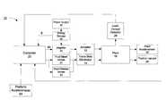
- an active suspension system 10includes an electromagnetic actuator 12 and a force bias eliminator 14 that cooperatively suspend a plant 16 above a platform (not shown).
- the system 10also includes a controller 20 that receives information from various sensors (including accelerometers 22 and 24 , position sensor 26 and load-unload detector 28 ) and controls operation of the actuator 12 and force bias eliminator 14 to keep plant 16 in roughly the same equilibrium position relative to the platform.
- the system 10is used in a truck cabin where a driver's seat constitutes the plant and the floor of the cabin constitutes the platform.
- the electromagnetic actuator 12receives electrical power from a power supply 30 via the controller.
- the controller 20uses information from the plant accelerometer 22 , platform accelerometer 24 and position sensor to generate control signal 40 that is used to modulate the output current of an amplifier 25 , which is supplied to the actuator.
- the electromagnetic actuatoris capable of responding very quickly to sudden, short changes in the vertical position of the platform. For example, if system 10 is used to suspend a truck seat, the actuator responds quickly as the truck travels over a sharp bump to keep the seat in about its equilibrium position above the floor. Because of this fast response, however, the actuator will draw high levels of power over short durations of time. Since the power supply 30 of the system (e.g., a truck's alternator or battery) may not be capable of providing adequate power, the system 10 is provided with an energy storage reservoir 32 , such as a bank of capacitors, to provide for such power.
- an energy storage reservoir 32such as a bank of capacitors
- the force bias eliminator 14is a pneumatic actuator that is connected to one or more fluid bleed valves 21 that supply compressed air to the force bias eliminator and one or more fluid release valves 23 that release air from the force bias eliminator.
- the controller 20controls the fluid bleed valves 21 and fluid release valves 23 to increase and decrease the upward force exerted by the force bias eliminator. Because the force bias eliminator is a pneumatic device, it does not have as fast a response as the electromagnetic actuator.
- the force bias eliminatoris used to counteract constant load of the plant (e.g., the weight of a driver sitting on a truck seat and the seat itself) and low frequency disturbances of the platform (such those caused when a truck travels over a long, undulating bump), while the electromagnetic actuator responds to higher frequency disturbances (such as the truck traveling over a sharp bump).
- constant load of the plante.g., the weight of a driver sitting on a truck seat and the seat itself
- low frequency disturbances of the platformsuch those caused when a truck travels over a long, undulating bump
- the electromagnetic actuatorresponds to higher frequency disturbances (such as the truck traveling over a sharp bump).
- the actuatorwill immediately operate to counteract a loading or unloading event until the force bias eliminator can respond.
- the actuatorwill immediately respond with an upward force to offset the weight of a driver when the driver sits down in the seat. The actuator will continue to exert this upward force until the force bias eliminator can respond and take over.
- the actuatorwill exert a downward force to resist the upward force being applied by the force bias eliminator. The actuator will continue to exert the downward force until the force bias eliminator can respond to relieve the actuator.
- the actuatordraws considerable current as it exerts this upward or downward force to counteract the effects of a loading or unloading event, causing it to quickly drain its energy storage reservoir (e.g., energy storage reservoir 32 shown in FIG. 1 ). If the actuator's energy storage reservoir empties prior to when the force bias eliminator is able to respond/take over, the actuator will lose power and the seat will suddenly drop (in a loading event) or raise (in an unloading event). This creates a potentially hazardous (or at least unpleasant) event.
- energy storage reservoire.g., energy storage reservoir 32 shown in FIG. 1
- the system 10is provided with a load-unload detector 28 , which indicates to the controller 20 that a loading or unloading event has occurred.
- the load-unload detectormay be implemented as a physical detector, such as a load detector, a weight sensor or a pressure sensor or it may be implemented as a virtual detector in software.
- the controller 20Upon detection of a loading or unloading event, the controller 20 will immediately cause the force bias eliminator 14 to quickly respond. Additionally, in some implementations including the implementation shown in FIG. 1 , the controller 20 may be configured to also slow the response of the actuator (as compared to the actuator normal response time) during a loading or unloading event.
- the load-unload detector 28serves as a “trip-wire” for the system, that will cause the controller to immediately respond, without waiting for other sensor signals (e.g., signals from accelerometers 22 or 24 or position sensor 26 ) and/or feedback control signals (not shown) that the controller 20 may receive from the actuator and/or force bias eliminator.
- sensor signalse.g., signals from accelerometers 22 or 24 or position sensor 26
- feedback control signalsnot shown
- the controller 20will immediately fully open all fluid bleed valves to cause a fluid (e.g., compressed air) to quickly fill the force bias eliminator until it reaches a point where it is exerting an upward force that counteracts the downward force exerted by the added load. Additionally, the controller 20 monitors the energy level E stored in the energy storage reservoir and progressively reduces the rate of discharge (e.g., by progressively reducing amount of current supplied to the actuator) as the energy storage reservoir 32 is progressively depleted.
- a fluide.g., compressed air
- the controllerwill fully open all fluid release valves to release the fluid from the force bias eliminator and thus eliminate the upward force it had supplied while the load was present.
- the controller 20will also progressively reduce the rate of discharge as the energy storage reservoir 32 is progressively depleted.
- the controllermay not directly measure the energy stored in the energy source. Rather, the controller may use a model of the characteristics of the power supply and/or energy storage reservoir to predict the level and discharge rate of available electrical energy. It should be noted that in some implementations the force bias eliminator may have a sufficiently fast response time that there is no need for the controller to slow the response time of the actuator to conserve energy.
- the fluid bleed and release valvesare preferably designed such that they permit for a fast response upon detection of a loading or unloading event, but are able to be controlled to accurately respond to low frequency disturbances encountered during operation.
- several bleed and/or release valvesare connected in parallel that permit rapid response during a loading or unloading event (e.g., by fully opening all valves at once) but permit precise injections or releases of fluid.
- a single bleed and/or release valveis employed that can respond quickly to pass a large volume of fluid but that can also be precisely controlled.
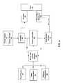
- the control system 40includes a compensator 42 that controls operation of the actuator 50 , and a control logic 44 that controls operation of the force bias eliminator 54 .
- the compensator 42 and control logic 44each have two modes of operation: a normal operation mode 55 A, 55 B and a loading/unloading operation mode 56 A, 56 B.
- a load/unload detector 46switches the compensator 42 and control logic 44 between the two modes of operation.
- the load/unload detector 46may be implemented as a physical sensor or a virtual detector (e.g., a virtual load/unload detector illustrated in FIGS. 4 and 5 ).
- the compensator 42 and control logic 44cooperatively suspend the plant 16 such that a first predetermined system performance criteria can be met.
- the compensator 42 and control logic 44cooperatively suspend the plant 16 to maintain a predetermined equilibrium position while minimizing the acceleration experienced by the plant 16 .
- the predetermined equilibrium positionmay correspond to the midpoint of stroke of the actuator 50 . Control of an actuator and force bias eliminator in normal operation is described in more detail in U.S. patent application Ser. No. 10/978,105 titled “Active Suspending” and filed Oct. 29, 2004.
- the load/unload detectorWhen the load/unload detector detects a loading or unloading event, it causes the compensator 42 and control logic 44 to immediately switch to the loading/unloading mode 56 A, 56 B. In this mode, the compensator receives a signal ( 51 ) indicating the electrical energy available in the energy store, and the level of current supplied to the actuator is decreased over time so as to preserve the energy in the energy store and extend the time the actuator can provide force.
- the control logic 42causes the force bias eliminator 54 to quickly respond to the loading/unloading event to relieve the actuator. Once the force bias eliminator responds to counteract the loading/unloading event (e.g., when the plant returns back to near its equilibrium position and has a velocity that is below a particular threshold), the system is switched back to its normal mode of operation.
- compensator 42 and/or control logic 44suspend the plant 16 such that a second predetermined system performance criteria can be met.
- a PID controlleris implemented in loading/unloading mode.
- FIGS. 3A and 3BThe performance of a system such as those shown in FIGS. 1 and 2 during a loading and unloading event is shown in FIGS. 3A and 3B , respectively.
- the plant 16undergoes a slight change in position (in the downward direction) when a loading event happens at time Ta, but does not come close to the lower limit of the plant's vertical travel (p ll ).
- the controlleropens fluid bleed valves at time Ta to rapidly raise the upward spring force of the force bias eliminator such that it has fully responded to the loading event at time Tb.
- the response of the force bias eliminatoris linear.
- the controllercontrols the actuator to quickly respond at time Ta with an upward force, but then rapidly decreases the upward force exerted by the actuator over the response time of the force bias eliminator such that the actuator is back to a “rest” state at time Tb.
- the controllerdecreases the upward force exerted by the actuator as a function of the energy available in the energy storage reservoir (e.g., element 32 in FIG. 1 ).
- the controllermonitors the level of available energy and controls the actuator such that the energy is linearly dissipated by the actuator at a rate that the energy storage reservoir will be depleted at approximately the same time as when the force bias eliminator responds (this is illustrated in the bottom graph of FIG. 3A ).
- the actuator forceramps down gently while the seat position is relaxed towards equilibrium. The force in the actuator during the loading and unloading event is no longer the difference between the spring force and the mass, but something smaller, dependent on the energy in the cap (voltage).
- the plantundergoes a slight change in position (in the upward direction) when an unloading event happens at time TA. As before, this change in position does not come close to the upper limit of the plant's vertical travel (p ul ).
- the controlleropens fluid release valves at time Ta to quickly reduce the upward spring force of the force bias eliminator such that it has fully responded to the unloading event at time Tb. As the force bias eliminator transitions to counteract the upward force caused by the unloading event at time Tb, the position of the seat is slightly lowered to its equilibrium position between its upper and lower limits of vertical travel (p ul and p ll respectively).
- the controllercontrols the actuator to quickly respond at time Ta with a downward force, but then rapidly decreases the downward force exerted by the actuator over the response time of the force bias eliminator such that the actuator is back to a “rest” state at time Th. As before, the controller gradually decreases the downward force exerted by the actuator as a function of the amount of available energy.
- the load-unload detectormay be implemented as a physical detector such as a pressure switch on the surface of the plant or as a “virtual” detector in software.
- FIG. 4illustrates an example of a virtual load-unload detector.
- a virtual load-unload detector 60receives the signals used to control the actuator (signal 73 ) and force bias eliminator (signal 71 ), one or both of the signals indicating the current position (signal 77 ) and acceleration of the plant (signal 79 ), and, in some implementations, the acceleration of the platform (signal 81 ).
- the virtual load-unload detectormonitors the control signals 71 , 73 and one or both of the current position 77 and acceleration signal 79 of the plant 68 to determine if the current vertical position and/or any current vertical movement of the plant is inconsistent with a vertical position and/or vertical movement that was expected, by a plant model, in response to the current state of the control signals 71 , 73 .
- the virtual load-unload detector 60watches for instances where the plant 68 is either at a vertical position or is moving vertically in a manner that is not what was expected to occur as a result of the manner in which the actuator 66 and the force bias eliminator 70 are being operated.
- a vertical position or vertical movement of the plant 68 that is inconsistent with what was expected in view of the current operation of the actuator 66 and the force bias eliminator 70tends to indicate that an external force is acting on the plant 68 in addition to whatever forces that the actuator 66 and/or the force bias eliminator 70 are exerting on the plant 66 through the control signals 71 , 73 .
- This inconsistencymay or may not be caused by loading or unloading event, and the virtual load-unload detector 60 attempts to distinguish between external forces causing such an inconsistency that arise from loading or unloading events from external forces that arise for other reasons.
- the virtual load-unload detector 60determines whether the external force have direction opposite or in the same direction of seat movement. Where there appears to be such a resistive external force (e.g., with direction opposite to the seat movement, and with a magnitude greater than a predetermined threshold), an assumption may be made by the virtual load-unload detector 60 that a frictional force indicative of a mechanical malfunction has occurred, and not a loading or unloading event. Where there appears to be an external force (of a magnitude greater than a predetermined threshold) that are in the same direction of the seat movement, the virtual load-unload detector 60 may presume that a loading or unloading event has occurred.
- the controllerWhen the virtual load-unload detector 60 determines that there has been a load-unload event, the controller will immediately respond to cause the force bias eliminator to counteract the load-unload event, and, in some implementations, actively manage the power drawn by the actuator so as not to rapidly deplete its energy source allowing the actuator to provide force for a longer time period.
- the force disturbancefor example, friction
- the change of loadwill manifest as a large force disturbance whose direction relates to the moving direction of the system. This feature enables us to use force disturbance with the position signal as an event signature to detect the occurrence of loading/unloading very quickly.
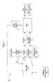
- a virtual load/unload detector 80includes a plant model 82 and an adaptive estimation algorithm 86 .
- the plant model 82takes the commanded force and floor acceleration as inputs to calculate a predicted suspension position.
- the suspension positionis defined as relative position between the plant and the floor.
- This predicted suspension positionis then compared with the measured suspension position to generate a prediction error.
- the prediction erroris fed into the adaptive estimation algorithm 86 , along with plant and motor acceleration, to estimate the force command disturbance that has caused the prediction error.
- the estimate force command disturbance together with the measured suspension position and velocityis passed to detection logic 92 where the signs and boundaries of the signals are checked against a set of disturbance isolation criteria.
- the detection logic 92detects whether the estimated force command has a magnitude greater than a predetermined threshold that is in the same direction as the measured plant velocity, the detection logic 92 will indicate a loading or unloading event has occurred.
Landscapes
- Engineering & Computer Science (AREA)
- Aviation & Aerospace Engineering (AREA)
- Transportation (AREA)
- Mechanical Engineering (AREA)
- Vehicle Body Suspensions (AREA)
- Current-Collector Devices For Electrically Propelled Vehicles (AREA)
- Seats For Vehicles (AREA)
Abstract
Description
Claims (21)
Priority Applications (6)
| Application Number | Priority Date | Filing Date | Title |
|---|---|---|---|
| US12/059,336US8112198B2 (en) | 2008-03-31 | 2008-03-31 | Loading and unloading stabilization in an active suspension system |
| EP09727989.7AEP2274180B1 (en) | 2008-03-31 | 2009-02-10 | Loading and unloading stabilization in an active suspension system |
| JP2011503000AJP5341981B2 (en) | 2008-03-31 | 2009-02-10 | Stabilization of loading and unloading in an active suspension system |
| CN200980112213.0ACN101983140B (en) | 2008-03-31 | 2009-02-10 | Active suspension system and control method thereof |
| HK11107126.9AHK1153176B (en) | 2008-03-31 | 2009-02-10 | Loading and unloading stabilization in an active suspension system |
| PCT/US2009/033654WO2009123792A1 (en) | 2008-03-31 | 2009-02-10 | Loading and unloading stabilization in an active suspension system |
Applications Claiming Priority (1)
| Application Number | Priority Date | Filing Date | Title |
|---|---|---|---|
| US12/059,336US8112198B2 (en) | 2008-03-31 | 2008-03-31 | Loading and unloading stabilization in an active suspension system |
Publications (2)
| Publication Number | Publication Date |
|---|---|
| US20090248246A1 US20090248246A1 (en) | 2009-10-01 |
| US8112198B2true US8112198B2 (en) | 2012-02-07 |
Family
ID=40577755
Family Applications (1)
| Application Number | Title | Priority Date | Filing Date |
|---|---|---|---|
| US12/059,336Active2030-12-08US8112198B2 (en) | 2008-03-31 | 2008-03-31 | Loading and unloading stabilization in an active suspension system |
Country Status (5)
| Country | Link |
|---|---|
| US (1) | US8112198B2 (en) |
| EP (1) | EP2274180B1 (en) |
| JP (1) | JP5341981B2 (en) |
| CN (1) | CN101983140B (en) |
| WO (1) | WO2009123792A1 (en) |
Cited By (31)
| Publication number | Priority date | Publication date | Assignee | Title |
|---|---|---|---|---|
| US8725351B1 (en) | 2012-10-31 | 2014-05-13 | Bose Corporation | Active suspension system |
| US8814468B1 (en) | 2013-02-12 | 2014-08-26 | Disney Enterprises, Inc. | Dynamic roll/pitch stabilizer for use during loading and unloading of small passenger boats |
| US9440508B2 (en) | 2014-11-25 | 2016-09-13 | Seth M. LACHICA | Active vehicle suspension system and method for managing drive energy |
| US9802520B2 (en) | 2013-12-16 | 2017-10-31 | Grammer Ag | Vehicle seat having a horizontally movable seating surface for receiving a person |
| US9846425B2 (en) | 2015-03-31 | 2017-12-19 | Bose Corporation | Retrieving pre-determined controller parameters to isolate vibrations in an authorized payload |
| US9849816B2 (en)* | 2013-06-04 | 2017-12-26 | Grammer Ag | Vehicle seat and motor vehicle or utility motor vehicle |
| US9879744B2 (en) | 2013-10-01 | 2018-01-30 | Grammer Ag | Vehicle with force-controlled shock absorber with regulating valve |
| US9937832B2 (en) | 2013-10-01 | 2018-04-10 | Grammer Ag | Vehicle seat or vehicle cabin having a suspension apparatus and utility vehicle |
| US9994239B2 (en) | 2013-10-01 | 2018-06-12 | Grammer Ag | Vehicle with force-controlled shock absorber (2-pipe shock absorber) |
| US10040330B2 (en) | 2013-03-15 | 2018-08-07 | ClearMotion, Inc. | Active vehicle suspension system |
| DE102017212225A1 (en) | 2017-07-18 | 2019-01-24 | Ford Global Technologies, Llc | Estimation of loads acting on a rear axle of a motor vehicle |
| US10814690B1 (en) | 2017-04-18 | 2020-10-27 | Apple Inc. | Active suspension system with energy storage device |
| US10899340B1 (en) | 2017-06-21 | 2021-01-26 | Apple Inc. | Vehicle with automated subsystems |
| US10906370B1 (en) | 2017-09-15 | 2021-02-02 | Apple Inc. | Active suspension system |
| US10960723B1 (en) | 2017-09-26 | 2021-03-30 | Apple Inc. | Wheel-mounted suspension actuators |
| US11046143B1 (en) | 2015-03-18 | 2021-06-29 | Apple Inc. | Fully-actuated suspension system |
| US11124035B1 (en) | 2017-09-25 | 2021-09-21 | Apple Inc. | Multi-stage active suspension actuator |
| US11173766B1 (en) | 2017-09-07 | 2021-11-16 | Apple Inc. | Suspension system with locking structure |
| US11179991B1 (en) | 2019-09-23 | 2021-11-23 | Apple Inc. | Suspension systems |
| US11285773B1 (en) | 2018-09-12 | 2022-03-29 | Apple Inc. | Control system |
| US11345209B1 (en) | 2019-06-03 | 2022-05-31 | Apple Inc. | Suspension systems |
| US11358431B2 (en) | 2017-05-08 | 2022-06-14 | Apple Inc. | Active suspension system |
| US11541713B2 (en) | 2015-12-24 | 2023-01-03 | ClearMotion, Inc. | Integrated multiple actuator electro-hydraulic units |
| US11634167B1 (en) | 2018-09-14 | 2023-04-25 | Apple Inc. | Transmitting axial and rotational movement to a hub |
| US11707961B1 (en) | 2020-04-28 | 2023-07-25 | Apple Inc. | Actuator with reinforcing structure for torsion resistance |
| US11828339B1 (en) | 2020-07-07 | 2023-11-28 | Apple Inc. | Vibration control system |
| US11938922B1 (en) | 2019-09-23 | 2024-03-26 | Apple Inc. | Motion control system |
| US12017498B2 (en) | 2021-06-07 | 2024-06-25 | Apple Inc. | Mass damper system |
| US12168375B1 (en) | 2023-01-26 | 2024-12-17 | Apple Inc. | Motion control system |
| US12179539B2 (en) | 2013-03-15 | 2024-12-31 | ClearMotion, Inc. | Active vehicle suspension system |
| US12251973B2 (en) | 2022-06-10 | 2025-03-18 | Apple Inc. | Vibration absorber |
Families Citing this family (5)
| Publication number | Priority date | Publication date | Assignee | Title |
|---|---|---|---|---|
| US9241850B2 (en) | 2011-09-02 | 2016-01-26 | Ferno-Washington, Inc. | Litter support assembly for medical care units having a shock load absorber and methods of their use |
| DE102014201010A1 (en)* | 2014-01-21 | 2015-07-23 | Airbus Operations Gmbh | System for supplying energy to an electric seat device in an aircraft or spacecraft |
| CN104816738A (en)* | 2014-10-23 | 2015-08-05 | 华东交通大学 | Method and apparatus for multi-velocity control of high-speed train electromagnetic active levitation system |
| US9643467B2 (en)* | 2014-11-10 | 2017-05-09 | Bose Corporation | Variable tracking active suspension system |
| CN104950667A (en)* | 2015-03-25 | 2015-09-30 | 华东交通大学 | Multi-rate prediction control method applied to train active suspension system |
Citations (15)
| Publication number | Priority date | Publication date | Assignee | Title |
|---|---|---|---|---|
| GB2138102A (en) | 1983-04-07 | 1984-10-17 | Isringhausen Geb | Control of pneumatic spring supporting vehicle seat |
| US4589620A (en) | 1983-12-20 | 1986-05-20 | Tachikawa Spring Co., Ltd. | Seat with an air suspension |
| US4664218A (en)* | 1984-10-05 | 1987-05-12 | National Emstop, Inc. | Safety back-up system for vehicles |
| US5582385A (en)* | 1995-04-27 | 1996-12-10 | The Lubrizol Corporation | Method for controlling motion using an adjustable damper |
| US5908456A (en)* | 1997-08-18 | 1999-06-01 | Caterpillar Inc. | Method for controlling a seat suspension system |
| US5975508A (en)* | 1995-09-06 | 1999-11-02 | Applied Power Inc. | Active vehicle seat suspension system |
| US6311110B1 (en)* | 1999-06-17 | 2001-10-30 | Lord Corporation | Adaptive off-state control method |
| US20010037169A1 (en)* | 2000-05-02 | 2001-11-01 | Clair Kenneth A. St. | Method for limiting endstop collisions in semi-active seat suspension systems |
| US20050098399A1 (en)* | 2002-11-13 | 2005-05-12 | Bremner Ronald D. | Active seat suspension control system |
| US20060095180A1 (en) | 2004-10-29 | 2006-05-04 | Ummethala Upendra V | Active suspending |
| US20060200287A1 (en) | 2004-10-29 | 2006-09-07 | Parison James A | Acting seating |
| US20090218867A1 (en)* | 2008-02-28 | 2009-09-03 | Bose Corporation | Plant Suspension System with Weight Compensation |
| US20100332079A1 (en)* | 2007-02-02 | 2010-12-30 | Gang Wang | Constant force control methodology for shock absorption |
| US7878312B2 (en)* | 2006-05-31 | 2011-02-01 | University Of Maryland | Adaptive energy absorption system for a vehicle seat |
| US7921973B2 (en)* | 2006-05-31 | 2011-04-12 | Techno-Sciences, Inc. | Adaptive energy absorption system for a vehicle seat |
Family Cites Families (1)
| Publication number | Priority date | Publication date | Assignee | Title |
|---|---|---|---|---|
| EP1468870B1 (en)* | 2003-04-14 | 2006-06-07 | Grammer Ag | Device and method for the suspension of a vehicle seat. |
- 2008
- 2008-03-31USUS12/059,336patent/US8112198B2/enactiveActive
- 2009
- 2009-02-10JPJP2011503000Apatent/JP5341981B2/enactiveActive
- 2009-02-10WOPCT/US2009/033654patent/WO2009123792A1/enactiveApplication Filing
- 2009-02-10CNCN200980112213.0Apatent/CN101983140B/enactiveActive
- 2009-02-10EPEP09727989.7Apatent/EP2274180B1/enactiveActive
Patent Citations (17)
| Publication number | Priority date | Publication date | Assignee | Title |
|---|---|---|---|---|
| GB2138102A (en) | 1983-04-07 | 1984-10-17 | Isringhausen Geb | Control of pneumatic spring supporting vehicle seat |
| US4589620A (en) | 1983-12-20 | 1986-05-20 | Tachikawa Spring Co., Ltd. | Seat with an air suspension |
| US4664218A (en)* | 1984-10-05 | 1987-05-12 | National Emstop, Inc. | Safety back-up system for vehicles |
| US5582385A (en)* | 1995-04-27 | 1996-12-10 | The Lubrizol Corporation | Method for controlling motion using an adjustable damper |
| US5975508A (en)* | 1995-09-06 | 1999-11-02 | Applied Power Inc. | Active vehicle seat suspension system |
| US5908456A (en)* | 1997-08-18 | 1999-06-01 | Caterpillar Inc. | Method for controlling a seat suspension system |
| US6311110B1 (en)* | 1999-06-17 | 2001-10-30 | Lord Corporation | Adaptive off-state control method |
| US20010037169A1 (en)* | 2000-05-02 | 2001-11-01 | Clair Kenneth A. St. | Method for limiting endstop collisions in semi-active seat suspension systems |
| US20050098399A1 (en)* | 2002-11-13 | 2005-05-12 | Bremner Ronald D. | Active seat suspension control system |
| US20060095180A1 (en) | 2004-10-29 | 2006-05-04 | Ummethala Upendra V | Active suspending |
| US20060200287A1 (en) | 2004-10-29 | 2006-09-07 | Parison James A | Acting seating |
| EP1782996A2 (en) | 2004-10-29 | 2007-05-09 | Bose Corporation | Active suspension |
| EP1652724B1 (en) | 2004-10-29 | 2008-01-09 | Bose Corporation | Active suspending |
| US7878312B2 (en)* | 2006-05-31 | 2011-02-01 | University Of Maryland | Adaptive energy absorption system for a vehicle seat |
| US7921973B2 (en)* | 2006-05-31 | 2011-04-12 | Techno-Sciences, Inc. | Adaptive energy absorption system for a vehicle seat |
| US20100332079A1 (en)* | 2007-02-02 | 2010-12-30 | Gang Wang | Constant force control methodology for shock absorption |
| US20090218867A1 (en)* | 2008-02-28 | 2009-09-03 | Bose Corporation | Plant Suspension System with Weight Compensation |
Non-Patent Citations (2)
| Title |
|---|
| International Preliminary Report on Patentability dated Oct. 14, 2010 for PCT/US2009/033654. |
| International Search Report and Written Opinion dated May 11, 2009 for PCT/US2009/033654. |
Cited By (47)
| Publication number | Priority date | Publication date | Assignee | Title |
|---|---|---|---|---|
| US8725351B1 (en) | 2012-10-31 | 2014-05-13 | Bose Corporation | Active suspension system |
| US8814468B1 (en) | 2013-02-12 | 2014-08-26 | Disney Enterprises, Inc. | Dynamic roll/pitch stabilizer for use during loading and unloading of small passenger boats |
| US10040330B2 (en) | 2013-03-15 | 2018-08-07 | ClearMotion, Inc. | Active vehicle suspension system |
| US11850905B2 (en) | 2013-03-15 | 2023-12-26 | ClearMotion, Inc. | Active vehicle suspension system |
| US12179539B2 (en) | 2013-03-15 | 2024-12-31 | ClearMotion, Inc. | Active vehicle suspension system |
| US11021033B2 (en) | 2013-03-15 | 2021-06-01 | ClearMotion, Inc. | Active vehicle suspension system |
| US9849816B2 (en)* | 2013-06-04 | 2017-12-26 | Grammer Ag | Vehicle seat and motor vehicle or utility motor vehicle |
| US9879744B2 (en) | 2013-10-01 | 2018-01-30 | Grammer Ag | Vehicle with force-controlled shock absorber with regulating valve |
| US9994239B2 (en) | 2013-10-01 | 2018-06-12 | Grammer Ag | Vehicle with force-controlled shock absorber (2-pipe shock absorber) |
| US9937832B2 (en) | 2013-10-01 | 2018-04-10 | Grammer Ag | Vehicle seat or vehicle cabin having a suspension apparatus and utility vehicle |
| US9802520B2 (en) | 2013-12-16 | 2017-10-31 | Grammer Ag | Vehicle seat having a horizontally movable seating surface for receiving a person |
| US9440508B2 (en) | 2014-11-25 | 2016-09-13 | Seth M. LACHICA | Active vehicle suspension system and method for managing drive energy |
| US11945279B1 (en) | 2015-03-18 | 2024-04-02 | Apple Inc. | Motion control system |
| US11046143B1 (en) | 2015-03-18 | 2021-06-29 | Apple Inc. | Fully-actuated suspension system |
| US10496073B2 (en) | 2015-03-31 | 2019-12-03 | Clearmotion Acquisition I Llc | Retrieving pre-determined controller parameters to isolate vibrations in an authorized payload |
| US9846425B2 (en) | 2015-03-31 | 2017-12-19 | Bose Corporation | Retrieving pre-determined controller parameters to isolate vibrations in an authorized payload |
| US11541713B2 (en) | 2015-12-24 | 2023-01-03 | ClearMotion, Inc. | Integrated multiple actuator electro-hydraulic units |
| US11964530B2 (en) | 2015-12-24 | 2024-04-23 | ClearMotion, Inc. | Integrated multiple actuator electro-hydraulic units |
| US10814690B1 (en) | 2017-04-18 | 2020-10-27 | Apple Inc. | Active suspension system with energy storage device |
| US12115827B2 (en) | 2017-05-08 | 2024-10-15 | Apple Inc. | Motion control system |
| US11701942B2 (en) | 2017-05-08 | 2023-07-18 | Apple Inc. | Motion control system |
| US11358431B2 (en) | 2017-05-08 | 2022-06-14 | Apple Inc. | Active suspension system |
| US11702065B1 (en) | 2017-06-21 | 2023-07-18 | Apple Inc. | Thermal management system control |
| US10899340B1 (en) | 2017-06-21 | 2021-01-26 | Apple Inc. | Vehicle with automated subsystems |
| DE102017212225B4 (en) | 2017-07-18 | 2021-07-08 | Ford Global Technologies, Llc | Estimation of loads acting on a rear axle of a motor vehicle |
| DE102017212225A1 (en) | 2017-07-18 | 2019-01-24 | Ford Global Technologies, Llc | Estimation of loads acting on a rear axle of a motor vehicle |
| US11173766B1 (en) | 2017-09-07 | 2021-11-16 | Apple Inc. | Suspension system with locking structure |
| US11065931B1 (en) | 2017-09-15 | 2021-07-20 | Apple Inc. | Active suspension system |
| US10906370B1 (en) | 2017-09-15 | 2021-02-02 | Apple Inc. | Active suspension system |
| US11124035B1 (en) | 2017-09-25 | 2021-09-21 | Apple Inc. | Multi-stage active suspension actuator |
| US12043073B1 (en) | 2017-09-25 | 2024-07-23 | Apple Inc. | Multi-stage active suspension actuator |
| US10960723B1 (en) | 2017-09-26 | 2021-03-30 | Apple Inc. | Wheel-mounted suspension actuators |
| US12097740B1 (en) | 2018-09-12 | 2024-09-24 | Apple Inc. | Control system |
| US11285773B1 (en) | 2018-09-12 | 2022-03-29 | Apple Inc. | Control system |
| US11634167B1 (en) | 2018-09-14 | 2023-04-25 | Apple Inc. | Transmitting axial and rotational movement to a hub |
| US12054028B1 (en) | 2019-06-03 | 2024-08-06 | Apple Inc. | Motion control systems |
| US11345209B1 (en) | 2019-06-03 | 2022-05-31 | Apple Inc. | Suspension systems |
| US11938922B1 (en) | 2019-09-23 | 2024-03-26 | Apple Inc. | Motion control system |
| US11731476B1 (en) | 2019-09-23 | 2023-08-22 | Apple Inc. | Motion control systems |
| US12134292B1 (en) | 2019-09-23 | 2024-11-05 | Apple Inc. | Motion control systems |
| US11179991B1 (en) | 2019-09-23 | 2021-11-23 | Apple Inc. | Suspension systems |
| US11707961B1 (en) | 2020-04-28 | 2023-07-25 | Apple Inc. | Actuator with reinforcing structure for torsion resistance |
| US11828339B1 (en) | 2020-07-07 | 2023-11-28 | Apple Inc. | Vibration control system |
| US12215747B1 (en) | 2020-07-07 | 2025-02-04 | Apple Inc. | Vibration control system |
| US12017498B2 (en) | 2021-06-07 | 2024-06-25 | Apple Inc. | Mass damper system |
| US12251973B2 (en) | 2022-06-10 | 2025-03-18 | Apple Inc. | Vibration absorber |
| US12168375B1 (en) | 2023-01-26 | 2024-12-17 | Apple Inc. | Motion control system |
Also Published As
| Publication number | Publication date |
|---|---|
| EP2274180B1 (en) | 2016-01-13 |
| CN101983140A (en) | 2011-03-02 |
| HK1153176A1 (en) | 2012-03-23 |
| JP5341981B2 (en) | 2013-11-13 |
| JP2011516333A (en) | 2011-05-26 |
| EP2274180A1 (en) | 2011-01-19 |
| US20090248246A1 (en) | 2009-10-01 |
| CN101983140B (en) | 2013-03-20 |
| WO2009123792A1 (en) | 2009-10-08 |
Similar Documents
| Publication | Publication Date | Title |
|---|---|---|
| US8112198B2 (en) | Loading and unloading stabilization in an active suspension system | |
| EP2914871B1 (en) | Active suspension system | |
| CN102649406B (en) | Apparatus for controlling active suspending device of vehicles | |
| KR102229026B1 (en) | Docking control for vessels | |
| US9592715B2 (en) | Method and apparatus for active dynamic trimming of suspension damping including negative stiffness | |
| EP0313030A2 (en) | Height control system in an automotive suspension system performing an attitude change supressive control and height regulating control with high response characteristics in a height adjustment | |
| KR101440239B1 (en) | Method and Apparatus for Controlling of Lift Axle of Vechile | |
| JP4816577B2 (en) | Vehicle height adjustment device | |
| US11485189B2 (en) | Weight estimation device, weight estimation method and non-transitory storage medium for vehicle | |
| CN110871655A (en) | Vehicle and method for suspension spring degradation detection and fault tolerant tire force estimation | |
| HK1153176B (en) | Loading and unloading stabilization in an active suspension system | |
| JPH085301B2 (en) | Truck bed height adjuster | |
| JPH0958242A (en) | Car height regulation device | |
| JP2007253842A (en) | Vehicle with vibration suppression function | |
| JP2024112429A (en) | Vehicle control device | |
| HK1088650B (en) | Active suspending | |
| HK1171992B (en) | An apparatus for controlling an actively-suspended plant in a vehicle | |
| HK1140730B (en) | Active suspending |
Legal Events
| Date | Code | Title | Description |
|---|---|---|---|
| AS | Assignment | Owner name:BOSE CORPORATION, MASSACHUSETTS Free format text:ASSIGNMENT OF ASSIGNORS INTEREST;ASSIGNORS:PARISON, JAMES A., JR.;SANGERMANO, II, ANTONIO;XU, YONGKA;REEL/FRAME:020905/0139 Effective date:20080424 | |
| AS | Assignment | Owner name:BOSE CORPORATION, MASSACHUSETTS Free format text:ASSIGNMENT OF ASSIGNORS INTEREST;ASSIGNORS:PARISON, JAMES A.;SANGERMANO, ANTONIO, II;XU, YONGKAI;REEL/FRAME:026006/0334 Effective date:20080424 | |
| STCF | Information on status: patent grant | Free format text:PATENTED CASE | |
| FPAY | Fee payment | Year of fee payment:4 | |
| AS | Assignment | Owner name:CLEARMOTION ACQUISITION I LLC, MASSACHUSETTS Free format text:NUNC PRO TUNC ASSIGNMENT;ASSIGNOR:BOSE CORPORATION;REEL/FRAME:044979/0806 Effective date:20171214 | |
| MAFP | Maintenance fee payment | Free format text:PAYMENT OF MAINTENANCE FEE, 8TH YEAR, LARGE ENTITY (ORIGINAL EVENT CODE: M1552); ENTITY STATUS OF PATENT OWNER: LARGE ENTITY Year of fee payment:8 | |
| AS | Assignment | Owner name:FRANKLIN STRATEGIC SERIES - FRANKLIN SMALL CAP GROWTH FUND, CALIFORNIA Free format text:PATENT SECURITY AGREEMENT;ASSIGNOR:CLEARMOTION, INC.;REEL/FRAME:058644/0007 Effective date:20211221 Owner name:FRANKLIN TEMPLETON INVESTMENT FUNDS - FRANKLIN U.S. OPPORTUNITIES FUND, CALIFORNIA Free format text:PATENT SECURITY AGREEMENT;ASSIGNOR:CLEARMOTION, INC.;REEL/FRAME:058644/0007 Effective date:20211221 Owner name:FRANKLIN STRATEGIC SERIES - FRANKLIN GROWTH OPPORTUNITIES FUND, CALIFORNIA Free format text:PATENT SECURITY AGREEMENT;ASSIGNOR:CLEARMOTION, INC.;REEL/FRAME:058644/0007 Effective date:20211221 Owner name:WIL FUND I, L.P., CALIFORNIA Free format text:PATENT SECURITY AGREEMENT;ASSIGNOR:CLEARMOTION, INC.;REEL/FRAME:058644/0007 Effective date:20211221 Owner name:ACADIA WOODS PARTNERS, LLC, NEW YORK Free format text:PATENT SECURITY AGREEMENT;ASSIGNOR:CLEARMOTION, INC.;REEL/FRAME:058644/0007 Effective date:20211221 Owner name:NEWVIEW CAPITAL FUND I, L.P., CALIFORNIA Free format text:PATENT SECURITY AGREEMENT;ASSIGNOR:CLEARMOTION, INC.;REEL/FRAME:058644/0007 Effective date:20211221 | |
| AS | Assignment | Owner name:ACADIA WOODS PARTNERS, LLC, NEW YORK Free format text:AMENDED & RESTATED PATENT SECURITY AGREEMENT;ASSIGNORS:CLEARMOTION, INC.;CLEARMOTION ACQUISITION I LLC;REEL/FRAME:059361/0433 Effective date:20220310 | |
| AS | Assignment | Owner name:BRILLIANCE JOURNEY LIMITED, VIRGIN ISLANDS, BRITISH Free format text:CORRECTIVE ASSIGNMENT TO CORRECT THE ADDING ASSIGNEE PREVIOUSLY RECORDED AT REEL: 059361 FRAME: 0433. ASSIGNOR(S) HEREBY CONFIRMS THE SECURITY AGREEMENT;ASSIGNORS:CLEARMOTION, INC.;CLEARMOTION ACQUISITION I LLC;REEL/FRAME:060130/0001 Effective date:20220310 Owner name:THE PRIVATE SHARES FUND, CALIFORNIA Free format text:CORRECTIVE ASSIGNMENT TO CORRECT THE ADDING ASSIGNEE PREVIOUSLY RECORDED AT REEL: 059361 FRAME: 0433. ASSIGNOR(S) HEREBY CONFIRMS THE SECURITY AGREEMENT;ASSIGNORS:CLEARMOTION, INC.;CLEARMOTION ACQUISITION I LLC;REEL/FRAME:060130/0001 Effective date:20220310 Owner name:TEW LIMITED PARTNERSHIP, MARYLAND Free format text:CORRECTIVE ASSIGNMENT TO CORRECT THE ADDING ASSIGNEE PREVIOUSLY RECORDED AT REEL: 059361 FRAME: 0433. ASSIGNOR(S) HEREBY CONFIRMS THE SECURITY AGREEMENT;ASSIGNORS:CLEARMOTION, INC.;CLEARMOTION ACQUISITION I LLC;REEL/FRAME:060130/0001 Effective date:20220310 Owner name:FHW LIMITED PARTNERSHIP, MARYLAND Free format text:CORRECTIVE ASSIGNMENT TO CORRECT THE ADDING ASSIGNEE PREVIOUSLY RECORDED AT REEL: 059361 FRAME: 0433. ASSIGNOR(S) HEREBY CONFIRMS THE SECURITY AGREEMENT;ASSIGNORS:CLEARMOTION, INC.;CLEARMOTION ACQUISITION I LLC;REEL/FRAME:060130/0001 Effective date:20220310 Owner name:MICROSOFT GLOBAL FINANCE, WASHINGTON Free format text:CORRECTIVE ASSIGNMENT TO CORRECT THE ADDING ASSIGNEE PREVIOUSLY RECORDED AT REEL: 059361 FRAME: 0433. ASSIGNOR(S) HEREBY CONFIRMS THE SECURITY AGREEMENT;ASSIGNORS:CLEARMOTION, INC.;CLEARMOTION ACQUISITION I LLC;REEL/FRAME:060130/0001 Effective date:20220310 Owner name:BRIDGESTONE AMERICAS, INC., TENNESSEE Free format text:CORRECTIVE ASSIGNMENT TO CORRECT THE ADDING ASSIGNEE PREVIOUSLY RECORDED AT REEL: 059361 FRAME: 0433. ASSIGNOR(S) HEREBY CONFIRMS THE SECURITY AGREEMENT;ASSIGNORS:CLEARMOTION, INC.;CLEARMOTION ACQUISITION I LLC;REEL/FRAME:060130/0001 Effective date:20220310 Owner name:WIL FUND I, L.P., CALIFORNIA Free format text:CORRECTIVE ASSIGNMENT TO CORRECT THE ADDING ASSIGNEE PREVIOUSLY RECORDED AT REEL: 059361 FRAME: 0433. ASSIGNOR(S) HEREBY CONFIRMS THE SECURITY AGREEMENT;ASSIGNORS:CLEARMOTION, INC.;CLEARMOTION ACQUISITION I LLC;REEL/FRAME:060130/0001 Effective date:20220310 Owner name:NEWVIEW CAPITAL FUND I, LP, CALIFORNIA Free format text:CORRECTIVE ASSIGNMENT TO CORRECT THE ADDING ASSIGNEE PREVIOUSLY RECORDED AT REEL: 059361 FRAME: 0433. ASSIGNOR(S) HEREBY CONFIRMS THE SECURITY AGREEMENT;ASSIGNORS:CLEARMOTION, INC.;CLEARMOTION ACQUISITION I LLC;REEL/FRAME:060130/0001 Effective date:20220310 Owner name:FRANKLIN STRATEGIC SERIES - FRANKLIN SMALL CAP GROWTH FUND, CALIFORNIA Free format text:CORRECTIVE ASSIGNMENT TO CORRECT THE ADDING ASSIGNEE PREVIOUSLY RECORDED AT REEL: 059361 FRAME: 0433. ASSIGNOR(S) HEREBY CONFIRMS THE SECURITY AGREEMENT;ASSIGNORS:CLEARMOTION, INC.;CLEARMOTION ACQUISITION I LLC;REEL/FRAME:060130/0001 Effective date:20220310 Owner name:FRANKLIN TEMPLETON INVESTMENT FUNDS - FRANKLIN U.S. OPPORTUNITIES FUND, CALIFORNIA Free format text:CORRECTIVE ASSIGNMENT TO CORRECT THE ADDING ASSIGNEE PREVIOUSLY RECORDED AT REEL: 059361 FRAME: 0433. ASSIGNOR(S) HEREBY CONFIRMS THE SECURITY AGREEMENT;ASSIGNORS:CLEARMOTION, INC.;CLEARMOTION ACQUISITION I LLC;REEL/FRAME:060130/0001 Effective date:20220310 Owner name:FRANKLIN STRATEGIC SERIES - FRANKLIN GROWTH OPPORTUNITIES FUND, CALIFORNIA Free format text:CORRECTIVE ASSIGNMENT TO CORRECT THE ADDING ASSIGNEE PREVIOUSLY RECORDED AT REEL: 059361 FRAME: 0433. ASSIGNOR(S) HEREBY CONFIRMS THE SECURITY AGREEMENT;ASSIGNORS:CLEARMOTION, INC.;CLEARMOTION ACQUISITION I LLC;REEL/FRAME:060130/0001 Effective date:20220310 Owner name:ACADIA WOODS PARTNERS, LLC, NEW YORK Free format text:CORRECTIVE ASSIGNMENT TO CORRECT THE ADDING ASSIGNEE PREVIOUSLY RECORDED AT REEL: 059361 FRAME: 0433. ASSIGNOR(S) HEREBY CONFIRMS THE SECURITY AGREEMENT;ASSIGNORS:CLEARMOTION, INC.;CLEARMOTION ACQUISITION I LLC;REEL/FRAME:060130/0001 Effective date:20220310 | |
| AS | Assignment | Owner name:CLEARMOTION ACQUISITION I LLC, MASSACHUSETTS Free format text:TERMINATION OF AMENDED & RESTATED PATENT SECURITY AGREEMENT;ASSIGNOR:ACADIA WOODS PARTNERS, LLC;REEL/FRAME:062687/0713 Effective date:20220906 Owner name:CLEARMOTION, INC., MASSACHUSETTS Free format text:TERMINATION OF AMENDED & RESTATED PATENT SECURITY AGREEMENT;ASSIGNOR:ACADIA WOODS PARTNERS, LLC;REEL/FRAME:062687/0713 Effective date:20220906 | |
| AS | Assignment | Owner name:CLEARMOTION ACQUISITION I LLC, MASSACHUSETTS Free format text:TERMINATION OF AMENDED & RESTATED PATENT SECURITY AGREEMENT;ASSIGNORS:FRANKLIN STRATEGIC SERIES - FRANKLIN GROWTH OPPORTUNITIES FUND ;FRANKLIN STRATEGIC SERIES - FRANKLIN SMALL CAP GROWTH FUND ;FRANKLIN TEMPLETON INVESTMENT FUNDS - FRANKLIN U.S. OPPORTUNITIES FUND ;AND OTHERS;REEL/FRAME:062705/0684 Effective date:20220906 Owner name:CLEARMOTION, INC., MASSACHUSETTS Free format text:TERMINATION OF AMENDED & RESTATED PATENT SECURITY AGREEMENT;ASSIGNORS:FRANKLIN STRATEGIC SERIES - FRANKLIN GROWTH OPPORTUNITIES FUND ;FRANKLIN STRATEGIC SERIES - FRANKLIN SMALL CAP GROWTH FUND ;FRANKLIN TEMPLETON INVESTMENT FUNDS - FRANKLIN U.S. OPPORTUNITIES FUND ;AND OTHERS;REEL/FRAME:062705/0684 Effective date:20220906 | |
| FEPP | Fee payment procedure | Free format text:MAINTENANCE FEE REMINDER MAILED (ORIGINAL EVENT CODE: REM.); ENTITY STATUS OF PATENT OWNER: LARGE ENTITY | |
| FEPP | Fee payment procedure | Free format text:11.5 YR SURCHARGE- LATE PMT W/IN 6 MO, LARGE ENTITY (ORIGINAL EVENT CODE: M1556); ENTITY STATUS OF PATENT OWNER: LARGE ENTITY | |
| MAFP | Maintenance fee payment | Free format text:PAYMENT OF MAINTENANCE FEE, 12TH YEAR, LARGE ENTITY (ORIGINAL EVENT CODE: M1553); ENTITY STATUS OF PATENT OWNER: LARGE ENTITY Year of fee payment:12 |