US8111966B2 - Wall box adapted to be mounted at a mid-span access location of a telecommunications cable - Google Patents
Wall box adapted to be mounted at a mid-span access location of a telecommunications cableDownload PDFInfo
- Publication number
- US8111966B2 US8111966B2US12/350,337US35033709AUS8111966B2US 8111966 B2US8111966 B2US 8111966B2US 35033709 AUS35033709 AUS 35033709AUS 8111966 B2US8111966 B2US 8111966B2
- Authority
- US
- United States
- Prior art keywords
- tray
- enclosure
- disposed
- wall box
- base
- Prior art date
- Legal status (The legal status is an assumption and is not a legal conclusion. Google has not performed a legal analysis and makes no representation as to the accuracy of the status listed.)
- Expired - Fee Related, expires
Links
Images


Classifications
- G—PHYSICS
- G02—OPTICS
- G02B—OPTICAL ELEMENTS, SYSTEMS OR APPARATUS
- G02B6/00—Light guides; Structural details of arrangements comprising light guides and other optical elements, e.g. couplings
- G02B6/44—Mechanical structures for providing tensile strength and external protection for fibres, e.g. optical transmission cables
- G02B6/4439—Auxiliary devices
- G02B6/444—Systems or boxes with surplus lengths
- G02B6/4441—Boxes
- G02B6/445—Boxes with lateral pivoting cover
- G—PHYSICS
- G02—OPTICS
- G02B—OPTICAL ELEMENTS, SYSTEMS OR APPARATUS
- G02B6/00—Light guides; Structural details of arrangements comprising light guides and other optical elements, e.g. couplings
- G02B6/24—Coupling light guides
- G02B6/36—Mechanical coupling means
- G02B6/38—Mechanical coupling means having fibre to fibre mating means
- G02B6/3807—Dismountable connectors, i.e. comprising plugs
- G02B6/3897—Connectors fixed to housings, casing, frames or circuit boards
- G—PHYSICS
- G02—OPTICS
- G02B—OPTICAL ELEMENTS, SYSTEMS OR APPARATUS
- G02B6/00—Light guides; Structural details of arrangements comprising light guides and other optical elements, e.g. couplings
- G02B6/44—Mechanical structures for providing tensile strength and external protection for fibres, e.g. optical transmission cables
- G02B6/4439—Auxiliary devices
- G02B6/444—Systems or boxes with surplus lengths
- G02B6/44528—Patch-cords; Connector arrangements in the system or in the box
- G—PHYSICS
- G02—OPTICS
- G02B—OPTICAL ELEMENTS, SYSTEMS OR APPARATUS
- G02B6/00—Light guides; Structural details of arrangements comprising light guides and other optical elements, e.g. couplings
- G02B6/44—Mechanical structures for providing tensile strength and external protection for fibres, e.g. optical transmission cables
- G02B6/4439—Auxiliary devices
- G02B6/444—Systems or boxes with surplus lengths
- G02B6/4453—Cassettes
- G02B6/4454—Cassettes with splices
- G—PHYSICS
- G02—OPTICS
- G02B—OPTICAL ELEMENTS, SYSTEMS OR APPARATUS
- G02B6/00—Light guides; Structural details of arrangements comprising light guides and other optical elements, e.g. couplings
- G02B6/44—Mechanical structures for providing tensile strength and external protection for fibres, e.g. optical transmission cables
- G02B6/4439—Auxiliary devices
- G02B6/444—Systems or boxes with surplus lengths
- G02B6/4453—Cassettes
- G02B6/4455—Cassettes characterised by the way of extraction or insertion of the cassette in the distribution frame, e.g. pivoting, sliding, rotating or gliding
- G—PHYSICS
- G02—OPTICS
- G02B—OPTICAL ELEMENTS, SYSTEMS OR APPARATUS
- G02B6/00—Light guides; Structural details of arrangements comprising light guides and other optical elements, e.g. couplings
- G02B6/44—Mechanical structures for providing tensile strength and external protection for fibres, e.g. optical transmission cables
- G02B6/4439—Auxiliary devices
- G02B6/4457—Bobbins; Reels
- H—ELECTRICITY
- H02—GENERATION; CONVERSION OR DISTRIBUTION OF ELECTRIC POWER
- H02G—INSTALLATION OF ELECTRIC CABLES OR LINES, OR OF COMBINED OPTICAL AND ELECTRIC CABLES OR LINES
- H02G3/00—Installations of electric cables or lines or protective tubing therefor in or on buildings, equivalent structures or vehicles
- H02G3/02—Details
- H02G3/08—Distribution boxes; Connection or junction boxes
- H02G3/081—Bases, casings or covers
- H02G3/083—Inlets
Definitions
- the principles disclosed hereinrelate to fiber optic cable systems. More particularly, the present disclosure relates to fiber optic cable systems for providing fiber to the premises.
- Passive optical networksare becoming prevalent in part because service providers want to deliver high bandwidth communication capabilities to customers. Passive optical networks are a desirable choice for delivering high speed communication data because they may not employ active electronic devices, such as amplifiers and repeaters, between a central office and a subscriber termination. The absence of active electronic devices may decrease network complexity and/or cost and may increase network reliability.
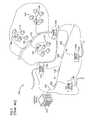
- FIG. 1illustrates a network 100 deploying passive fiber optic lines.
- the network 100may include a central office 110 that connects a number of end subscribers 115 (also called end users 115 herein) in a network.
- the central office 110may additionally connect to a larger network such as the Internet (not shown) and a public switched telephone network (PSTN).
- PSTNpublic switched telephone network
- the network 100may also include fiber distribution hubs (FDHs) 130 having one or more optical splitters (e.g., 1-to-8 splitters, 1-to-16 splitters, or 1-to-32 splitters) that generate a number of individual fibers that may lead to the premises of an end user 115 .
- the various lines of the networkcan be aerial or housed within underground conduits (e.g., see conduit 105 ).
- the portion of network 100 that is closest to central office 110is generally referred to as the F1 region, where F1 is the “feeder fiber” from the central office.
- the F1 portion of the networkmay include a distribution cable having on the order of 12 to 48 fibers; however, alternative implementations may include fewer or more fibers.
- the portion of network 100 that includes an FDH 130 and a number of end users 115may be referred to as an F2 portion of network 100 .
- Splitters used in an FDH 130may accept a feeder cable having a number of fibers and may split those incoming fibers into, for example, 216 to 432 individual distribution fibers that may be associated with a like number of end user locations.
- the network 100includes a plurality of break-out locations 125 at which branch cables are separated out from main cable lines.
- Breakout locationscan also be referred to as tap locations, drop cable locations, splice locations or branch locations.
- Branch cablescan also be referred to as drop cables, drop lines, breakout cables or stub cables.
- Branch cablesare often connected to drop terminals 104 that include connector interfaces for facilitating coupling the fibers of the branch cables to a plurality of different subscriber locations.
- Breakout locationsare often enclosed by a field mounted enclosure which protects optical splices (e.g., fusion or mechanical splices) or other types of optical couplings (e.g., connectorized optical couplings) provide at the breakout location. Since breakout locations are often provided at mid-span locations on the main cable being accessed, it desirable for field mounted enclosures to be readily mountable at mid-span access locations without requiring the main cable to be “threaded” lengthwise through the enclosure.
- optical splices
- Fiber optic networkscan extend to multi-dwelling units such as apartment buildings and condominiums.
- FIG. 2shows a fiber optic network including a cable 150 routed into a multi-dwelling unit 152 .
- branch cables/fibersare optically coupled to the fibers of the cable 150 at optical coupling locations (e.g., fusion splices, mechanical splices or connectorized optical couplings).
- the optical coupling locationscan be enclosed within one or more wall boxes that are typically equipped with doors/covers that can be opened to provide easy access to the optical coupling locations.
- the wall boxesare typically provided at different floors of the multi-dwelling unit with each wall box having optical coupling locations corresponding to a plurality of different subscribers (e.g., each resident on a given floor).
- the wall boxcan include structure that facilitates mounting the wall box at a mid-span access location of a fiber optic cable.
- An aspect of the present disclosurerelates to a wall box including an enclosure.
- the enclosurehas a base and a front cover connected to the base. The base and the front cover cooperate to enclose an interior region of the enclosure.
- the wall boxfurther includes a plurality of fiber optic adapters mounted to the enclosure.
- the fiber optic adaptersinclude an inner port positioned inside the interior region and an outer port positioned at an outer surface of the enclosure.
- a tray stackis mounted within the interior region of the enclosure.
- the tray stackincludes a tray mount pivotally connected to the enclosure.
- the tray mountincludes a top surface and an oppositely disposed bottom surface.
- a first splice tray mounting areais disposed on the top surface and a second splice tray mounting area is disposed on the bottom surface.
- a plurality of traysis disposed in the first splice tray mounting area.
- a trayis disposed in the second splice tray mounting area.
- a wall boxincluding an enclosure.
- the enclosurehas a base and a cover pivotally connected to the base.
- the base and the covercooperate to enclose an interior region of the enclosure.
- a hinge assemblypivotally connects the cover to the base.
- the hinge assemblyincludes at least one pin member and at least one hinge portion.
- the hinge portionhas a free end defining an opening that is adapted to selectively receive the pin member.
- a retention memberis adapted to retain the pin member in the opening of the hinge portion.
- the retention memberis a resilient member having a first end portion and an oppositely disposed second end portion.
- the second end portionis adapted to block at least a portion of the opening in a relaxed position to retain the pin member in the opening.
- the wall boxfurther includes a plurality of fiber optic adapters mounted to the enclosure.
- the fiber optic adaptersinclude an inner port positioned inside the interior region and an outer port positioned at an outer surface of the enclosure.
- FIG. 1shows a prior art passive fiber optic network.
- FIG. 2shows another prior art passive fiber optic network.
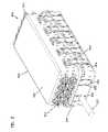
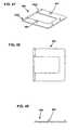
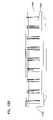
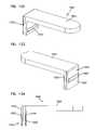
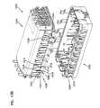
- FIG. 3is a perspective view of another wall box in accordance with the principles of the present disclosure, a cable is shown routed through a first pass-through path defined by the wall box.
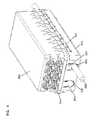
- FIG. 4is a perspective view of the wall box of FIG. 3 from an opposite perspective as the view of FIG. 3 .
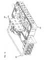
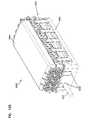
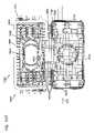
- FIG. 5shows the wall box of FIGS. 3 and 4 in an open configuration with various components exploded outwardly from the interior of the wall box.
- FIG. 6is top side view of the wall box of FIG. 3 .
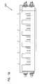
- FIG. 7is a front view of the wall box of FIG. 3 .
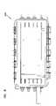
- FIG. 8is a back view of the wall box of FIG. 3 .
- FIG. 9is a right, end view of the wall box of FIG. 3 .
- FIG. 10is a back view of the wall box of FIG. 3 shown in combination with a wall mounting bracket.
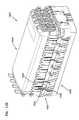
- FIG. 11is a perspective view of the wall box of FIG. 3 showing the wall box in an open configuration.
- FIG. 12shows a wall box of FIG. 11 with several splice trays pivoted outwardly.
- FIG. 13shows the wall box of FIG. 11 with the entire splice tray assembly swung outwardly to a position where the pass-through cable can be readily accessed within the wall box.
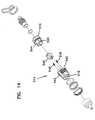
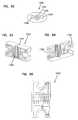
- FIG. 14is an exploded view of a fiber optic adapter suitable for use with the wall box devices of FIGS. 3-13 .
- FIG. 15is a longitudinal cross-sectional view of the fiber optic adapter of FIG. 14 .
- FIG. 16shows a fiber optic connector adapted to be inserted in an outer port of the fiber optic adapter of FIGS. 14 and 15 .
- FIG. 17is a perspective view of a cover of the wall box of FIG. 3 .
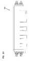
- FIG. 18is a front view of the cover of FIG. 17 .
- FIG. 19is a top view of the cover of FIG. 18 .
- FIG. 20is a bottom view of the cover of FIG. 18 .
- FIG. 21is a right, end view of the cover of FIG. 18 .
- FIG. 22is a left, end view of the cover of FIG. 18 .
- FIG. 23is a rear view of the cover of FIG. 18 .
- FIG. 24is a perspective view of a base of the wall box of FIG. 3 .
- FIG. 25is a back view of the base of FIG. 24 .
- FIG. 26is a top view of the base of FIG. 25 .
- FIG. 27is a bottom view of the base of FIG. 25 .
- FIG. 28is a right, end view of the base of FIG. 25 .
- FIG. 29is a left, end view of the base of FIG. 25 .
- FIG. 30is a front view of the base of FIG. 25 .
- FIGS. 31-37show various views of a cable pass-through insert used with the wall box of FIG. 3 .
- FIGS. 38-44show various views of a cable pass-through plug used with the wall box of FIG. 3 .
- FIG. 45shows a splitter tray used with the wall box of FIG. 3 .
- FIG. 46shows a splice tray used with the wall box of FIG. 3 .
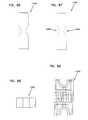
- FIGS. 47-53show a pivotal tray mount used with the wall box of FIG. 3 .
- FIGS. 54-56show various views of a tray stack.
- FIGS. 57-61show various views of a dual hinge pin component used with the tray stack of FIGS. 54-56 .
- FIGS. 62-66show various views of a hinge linkage used with the tray stack of FIGS. 54-56 .
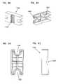
- FIGS. 67-71show various views of a cable management finger that mounts beneath the tray stack of FIGS. 54-56 .
- FIGS. 72-76show various views of a latching clip used with the tray stack of FIGS. 54-56 .
- FIGS. 77-81show various views of a cable management finger used within the wall box of FIGS. 3-13 .
- FIG. 82is a cross-sectional view of a drop cable.
- FIGS. 83-96show various views of components of a yoke adapted for clamping the drop cable of FIG. 81 .
- FIGS. 97-100show shroud arrangements for covering the wall box of FIGS. 3-13 .
- FIGS. 101-105show various views of alternate embodiment of a tray mount suitable for use within the wall box of FIG. 3 .
- FIGS. 106-107show various views of a splice tray stack suitable for use with the tray mount of FIGS. 101-105 .
- FIGS. 108-114show various views of an alternate embodiment of a cover suitable for use with the wall box of FIG. 3 .
- FIGS. 115-121show various views of an alternate embodiment of a base suitable for use with the wall box of FIG. 3 .
- FIGS. 122-124show various views of an alternate embodiment of a cable management finger suitable for use with the wall box of FIG. 3 .
- FIGS. 125-126show various views of an alternate embodiment of a wall box in accordance with the principles of the present disclosure.
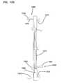
- FIGS. 127-128show various views of a grommet for use in the wall box of FIG. 125 .
- FIG. 129is a top view of a base of the wall box of FIG. 125 .
- FIGS. 130-131are various views of a fastener suitable for use with the wall box of FIG. 125 .
- FIG. 132is a view of an interior cavity of the wall box of FIG. 125 .
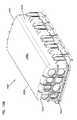
- FIG. 133is a perspective view of a cover of the wall box of FIG. 125 .
- FIG. 134is a perspective view of a cable management tray suitable for use with the wall box of FIG. 125 .
- FIGS. 135-136are various views of a fanout holder suitable for use with the wall box of FIG. 125 .
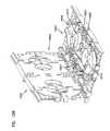
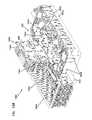
- FIG. 137is a view of the wall box of FIG. 144 showing an exemplary cable routing scheme.
- FIG. 138is an exploded perspective view of a base and a cover of the wall box of FIG. 125 .
- FIG. 139is a perspective view of a hinge assembly suitable for use with the wall box of FIG. 125 .
- the present disclosurerelates generally to wall boxes configured to be easily mounted at mid-span locations along the length of a fiber optic telecommunications cable. It is preferred for wall boxes in accordance with the principles of the present disclosure to be used for indoor applications such as multi-dwelling units, or commercial buildings where a plurality of subscribers is located. However, it will be appreciated that wall boxes in accordance with the principles of the present disclosure can be used for either indoor or outdoor applications wherever it is desired to easily mount an enclosure at a mid-span location of a telecommunications cable. Certain embodiments can be sealed for use in below grade applications (e.g., for use in hand holes).
- FIGS. 3-13show a wall box 900 having features in accordance with the principles of the present disclosure.
- the wall box 900includes an enclosure 902 having a base 916 and a front cover 920 that cooperate to enclose an interior region of the enclosure 902 .
- the front cover 920is pivotally connected to the base 916 by hinges 921 located at a first side of the enclosure 902 .
- a plurality of latches 923is located at the side of the enclosure opposite from the hinges 921 .
- the latches 923are configured to secure the front cover 920 in a closed position relative to the base 916 .
- Groupings of fiber optic adapters 514are mounted at opposite ends of the front cover 920 .
- FIG. 14illustrates one of the fiber optic adapters 514 in isolation from the wall boxes.
- the fiber optic adapter 514includes a main housing 540 having a first piece 542 that defines the inner port 518 of the fiber optic adapter 514 and a second piece 544 that defines the outer port 516 of the fiber optic adapter 514 .
- the first and second pieces 542 , 544can be interconnected by a snap-fit connection to form the main housing 540 .
- a split sleeve housing 546mounts within the interior of the main housing 540 .
- Springs 548bias the split sleeve housing 546 toward the outer port 516 and allow the split sleeve housing 546 to float within the interior of the main housing 540 . As shown in FIG.
- the split sleeve housing 546houses a standard split sleeve 550 that is coaxially aligned with a center axis 552 of the fiber optic adapter 514 .
- the split sleeve 550includes a first end 554 that faces toward the inner port 518 of the fiber optic adapter 514 and a second end 556 that faces toward the outer port 516 of the fiber optic adapter 514 .
- the fiber optic adapter 514mounts within one of the adapter mounting openings defined by the wall boxes.
- the fiber optic adapter 514is retained within the adapter mounting opening by a retention nut 560 threaded on exterior threads defined by the first piece 542 of the main housing 540 .
- the corresponding adapter mounting wallis captured between the retention nut 560 and a shoulder 564 of the main housing 540 .
- a sealing member 566is compressed between the main housing 540 and the adapter mounting wall to provide an environmental seal about the adapter mounting opening.
- a dust cap 568is shown mounted covering the inner port 518 of the fiber optic adapter 514 and a plug 570 is shown mounted within the outer port 516 of the fiber optic adapter 514 .
- the plug 570is threaded within internal threads 572 defined within the outer port 516 .
- the plug 570also includes a sealing member 574 (e.g., an O-ring) that engages a sealing surface 576 within the outer port 516 to provide an environmental seal between the main housing 540 and the plug 570 .
- a strap 578secures the plug 570 to the main housing 540 to prevent the plug from being misplaced when removed from the outer port 516 .
- the fiber optic adapters 514are mounted within the adapter mounting openings defined through the front covers of the wall boxes.
- the dust caps 568can be removed to allow the fiber optic connectors 530 terminated to the pigtail optical fibers 528 spliced to corresponding fibers of the main cable to be inserted into the inner ports 518 .
- ferrules of the inner fiber optic connectors 530are received within the first ends 554 of the split sleeves 550 , and clips 580 function to retain the inner fiber optic connectors 530 within the inner ports 518 .
- the plug 570 of one of the fiber optic adapters 514is removed from its corresponding outer port 516 to allow an exterior fiber optic connector terminated to the drop cable to be inserted into the outer port 516 .
- An example exterior fiber optic connector 582 mounted at the end of a drop cable 590is shown at FIG. 16 .
- the exterior fiber optic connector 582includes a housing 584 on which a retention nut 586 is rotatably mounted. The retention nut 586 can be manually rotated about a central axis 588 of the exterior fiber optic connector 582 .
- the drop cable 590includes an optical fiber 592 having an end portion mounted within a ferrule 594 supported at one end of the housing 584 .
- the ferrule 594is received within second end 556 of the split sleeve 550 .
- the split sleeve 550holds the ferrule of the inner fiber optic connector 530 in coaxial alignment with the ferrule 594 of the exterior fiber optic connector 582 .
- the corresponding optical fibers 528 , 592 held within the ferrulesare placed in coaxial alignment thereby allowing light signals to be transferred from fiber to fiber.
- the exterior fiber optic connector 582is retained within the outer port 516 by threading the retention nut 586 into the internal threads 572 .
- the exterior fiber optic connector 582includes a sealing member 596 (e.g., an O-ring) that engages the sealing surface 576 to provide an environmental seal between the exterior fiber optic connector 582 and the fiber optic adapter 514 .
- a sealing member 596e.g., an O-ring
- the base 916defines two sets of cable exit/enter openings 932 for allowing a telecommunications cable 933 to be routed through the enclosure 902 .
- the sets of cable exit/enter openings 932are aligned along axes 929 defining cable pass-through paths that extend through the enclosure 902 .
- the cable exit/enter openings 932can be enclosed by plug inserts 935 (see FIGS. 38-44 ) when cables are not being routed through the openings 932 .
- Cable pass-through inserts 937are used to seal the openings 932 when cables 933 are routed through the openings 932 .
- Fasteners 939are used to secure the inserts 935 , 937 to the base 916 .
- a gasket 940provides a seal between the front cover 920 and the base 916 when the cover 920 is closed.
- the gasket 940fits within a groove 942 that extends around the perimeter of an open side of the base 916 .
- the inserts 935 , 937include recesses, depressions or grooves 943 that align with the channel 942 and that receive the gasket 940 when the gasket is mounted within the channel 942 .
- a tray stack 949is mounted within the interior of the enclosure 902 .
- the tray stack 949includes a splitter tray 950 (see FIG. 45 ) and a plurality of splice trays 952 (see FIG. 46 ).
- One or more splitters 953can be mounted on the splitter tray 950 .
- a 1 ⁇ 16 splitter or two 1 ⁇ 8 splitterscan be mounted on the splitter tray 950 .
- a fiber 917 from the cable 933 routed through the enclosure 902can be terminated at a mid-span access location located within the enclosure 902 .
- the terminated optical fiber 917can be spliced to an input 919 of the splitter 953 at one of the splice trays 952 .
- Output fibers 957 of the splitter 953can be routed to a fan-out 955 location where the output fibers 957 are upjacketed.
- the upjacketed output fibers 957 from the splitter 953are preferably connectorized so as to form connectorized pigtails that are plugged into the inner ports of the fiber optic adapters 514 .
- fibers of the pass-through cable 933can be accessed and spliced directly to connectorized pigtails without using an intermediate splitter.
- fibers accessed at the mid-span access location of the pass-through cable 933can be spliced to distribution cables routed out of the wall box 900 through otherwise unused cable exit/enter openings 932 .
- the splitter tray 950 and the splice trays 952can be pivotally mounted within the enclosure 902 .
- the trays 950 , 952can be mounted to or carried by a pivotal tray mount 960 (see FIGS. 47-53 ) that is pivotally connected to the base 916 by a hinge arrangement.
- the hinge arrangementcan include pin cradles 1020 (see FIGS. 25 and 26 ) sized to pivotally receive pivot pins 1022 that are integral with the pivotal tray mount 960 .
- Brackets 1021see FIG.
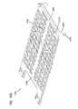
- the cable spooling region 1228includes a plurality of spools 980 integrally formed with the base 916 .
- An unjacketed mid-span portion 1032 of the pass-through cable 933can be spooled around the outsides of the spools 980 for storage purposes.
- the unjacketed mid-span portion 1232typically includes a plurality of exposed buffer tubes of the cable 933 . Fibers within the buffer tubes can be accessed, terminated and spliced to the input 919 of a splitter 953 (see FIG. 45 ) at one of the splice trays 952 . Terminated fibers from the pass-though cable 933 can be spliced directly to connectorized pigtails at the splice trays 952 , or can be spliced to branch cables (e.g., drop cables) routed out of the wall box 900 .
- branch cablese.g., drop cables
- each of the trays 950 , 952can be pivoted at once to an open position where the pass-through can be readily accessed (see FIG. 13 ). It is also preferred for each of the trays 950 , 952 to be individually pivotally moveable relative to each other.
- the bottommost traycan be connected to the mount 960 , while each subsequent stacked tray is pivotally connected to the tray beneath it.
- Hinge pin receivers 963can be provided on the mount 960 and are adapted to receive corresponding pins provided on the bottommost tray. This type of arrangement facilitates accessing individual trays for splicing or cable management.
- FIGS. 11-13the pivotal arrangement of tray 950 , 952 is depicted.
- FIG. 11shows all of the trays pivoted to a closed position.
- FIG. 12shows two of the trays pivoted to open positions while a third tray remains in a closed position.
- FIG. 13shows the mount 960 pivoted to an open position in which all of the trays have been moved to a position where the pass-through cable can be readily accessed.
- the tray mount 1561includes a first end portion 1562 and an oppositely disposed second end portion 1564 .
- the first end portion 1562includes a pin member 1566 that is adapted to be received in the pin cradles 1020 of the base 916 .
- the second end portion 1564includes a plurality of resilient latches 1568 .
- the resilient latches 1568extend downwardly from a top surface 1570 of the tray mount 1561 .
- Each of the plurality of resilient latches 1568includes a base portion 1572 , which is engaged with the tray mount 1561 , and a latching portion 1574 .
- the latching portion 1574includes a lip 1576 that extends outwardly from the latching portion 1574 .
- the tray mount 1561further includes a first splice tray mounting area 1578 disposed on the top surface 1570 of the tray mount 1561 .
- a plurality of splice tray mounts 1580is disposed in the first splice tray mounting area 1578 and extends upwardly from the top surface 1570 .
- Each of the splice tray mounts 1580includes a base end 1582 , which is engaged with the tray mount 1561 , and a latching end 1584 .
- the latching end 1584includes a lip portion 1586 that extends outwardly from the latching end 1584 .
- the lip portion 1586is adapted for engagement with a splice tray.
- the tray mount 1561includes a second splice tray mounting area 1587 disposed on a bottom surface 1590 of the tray mount 1561 .
- a splitter tray 1592 having a splitter mounted thereonis disposed in the second splice tray mounting area 1587 of the bottom surface 1590 while a splice tray stack 1800 is disposed in the first splice tray mounting area 1578 of the top surface 1570 .
- the splice tray stack 1800suitable for use with the tray mount 1561 is shown.
- the splice tray stack 1800includes two splice trays 1802 that mount to the tray mount 1561 .
- the splice trays 1802include two splice mounting locations 1804 .
- a fiber storage region 1806 for storing fibersis generally disposed between the two splice mounting locations 1804 .
- the fiber storage region 1806includes two spaced apart half spools 1808 about which excess fiber can be spooled.
- the fiber storage regionalso includes two full spools 1810 positioned in an area defined between the two half spools 1808 .
- Each of the two full spools 1810includes a catch 1811 .
- Each catch 1811is adapted to receive one of the lip portions 1586 of the latching ends 1584 of the splice tray mounts 1580 of the tray mount 1561 .
- the fiber storage region 1806further includes curved fiber guides 1812 located at inside edges of each of the splice mounting locations 1804 .
- the fiber storage region 1806further includes a central bend radius limiter 1814 positioned between the two full spools 1810 .
- the half spools 1808define an outer fiber storage loop path 1816 that extends around exterior surfaces of the half spools 1808 and also extends along the fiber guides 1812 positioned adjacent the splice mounting locations 1804 .
- the full spools 1810define an inner loop path 1818 that extends around exterior surfaces of the full spools 1810 .
- the inserts 935 , 937are configured to nest within the cable exit/enter openings 932 .
- the insert 935has a lower portion 990 having a convex groove and rail arrangement 1250 that mates/intermeshes with a corresponding concave groove and rail arrangement 1252 defined by the base 916 at the cable exit/enter openings 932 .
- the insert 937has a concave groove and rail arrangement 991 that cooperates with the concave groove and rail arrangement 1252 of the cable exit/enter openings 932 so as to clamp jacketed portions of the pass-through cable in place relative to the enclosure 902 when the insert is fastened to the base 916 .
- Tape or other materialcan be wrapped about the portion of the cable 933 (e.g., around the jacket) that passes through the cable exit/enter opening 932 to provide a better environmental seal.
- the inserts 935 , 937also define fastener openings 987 for receiving the fasteners 939 .
- the fastener openings 987are defined through projecting portions 994 of the inserts 935 , 937 .
- the projecting portions 994project outwardly from main bodies of the inserts 935 , 937 and fit within corresponding receptacles or channels 1254 provided at the cable exit/enter openings 932 to facilitate aligning the inserts within the openings 932 .
- the main bodies of the inserts 935 , 937have tapered configurations that match corresponding tapers of the cable exit/enter openings 932 . In contrast the projecting portions 994 and their corresponding channels 1254 are not tapered.
- the base 916includes sets of inner and outer end walls 1256 , 1258 between which the inserts 935 , 937 mount.
- Walls 1256 , 1258define notches 1260 , 1062 aligned with the cable exit/enter openings 932 .
- the inserts 935 , 937include inner and outer end projections 1264 , 1266 that fit with in the notches 1260 , 1262 of the inner and outer walls 1256 , 1258 .
- the projections 1264 , 1266are shaped to generally complement the shapes of the notches 1260 , 1262 .
- the base 916is configured to interconnect with a mounting bracket 970 that facilitates mounting the enclosure 902 to a structure such as a wall or pole.
- the mounting brackethas fastener openings 971 for allowing the bracket 970 to be pre-mounted to a structure such as a wall or pole.
- the mounting bracket 970also includes a pair of end portions 972 that fit within slots 997 defined by rails 973 provided on the base 916 of the enclosure 902 to secure the enclosure 902 to the bracket 970 .
- the bracket 970is pre-mounted to the pole or wall.
- the enclosure 902is positioned above the bracket 970 with the slots 997 in alignment with the end portions 972 .
- bracket 970engages the bottom ends of the rails 973 when the enclosure 902 is fully engaged with the bracket 970 .
- the tabs 995can snap within openings defined by the enclosure 902 or otherwise provide a snap-fit connection with the enclosure to provide a more secure connection between the bracket 970 and the enclosure 902 .
- FIGS. 17-23show the cover 920 in isolation from the base 916 .
- the coveris generally rectangular and has an open interior to allow pigtails to be readily routed to the adapters 514 .
- Integral hinge hooks 1500are provided at one side of the cover 920 while latch mounts are provided at the opposite side of the cover.
- cable management structuressuch as spools can be provided within the interior of the cover.
- FIGS. 108-114show an alternate embodiment of a cover 1620 suitable for use with the enclosure 902 .
- the cover 1620includes a front side 1622 , a first wall 1624 , an oppositely disposed second wall 1626 , a first side 1628 and an oppositely disposed second side 1630 .
- the first and second walls 1624 , 1626 and the first and second sides 1628 , 1630are arranged in a generally rectangular configuration.
- the front side 1622is generally arcuate in shape.
- the front side 1622 , the first and second walls 1624 , 1626 , and the first and second sides 1628 , 1630cooperatively define an interior 1632 having an opening 1634 .
- an inner surface 1636 of the front side 1622includes a plurality of ridges 1638 disposed in a waffle pattern. The plurality of ridges 1638 provide added strength to the front side 1622 .
- each of the first and second sides 1628 , 1630includes an interior surface on which is disposed a plurality of ribs 1640 .
- the plurality of ribs 1640extend from the opening 1634 to the inner surface 1636 of the front side 1622 .
- the plurality of ribs 1640are adapted to provide strength to the first and second walls 1624 , 1626 and the first and second sides 1628 , 1630 .
- Each of the first and second walls 1624 , 1626defines a plurality of adapter openings 1642 that extend into the interior 1632 of the cover 1620 .
- a first plurality of ribs 1644is disposed on an interior surface of the first and second walls 1624 , 1626 . In the subject embodiment, the first plurality of ribs 1644 is longitudinally disposed between adjacent adapter openings 1642 .
- a second plurality of ribs 1646is disposed on an exterior surface of the first and second walls 1624 , 1626 .
- the second plurality of ribs 1646includes a plurality of longitudinal ribs 1648 and a latitudinal rib 1650 .
- the longitudinal ribs 1648 and the latitudinal rib 1650are disposed between adjacent adapter openings 1642 .
- the first and second plurality of ribs 1646are adapted to provide strength to the interior and exterior surfaces of the first and second walls 1624 , 1626 .
- Integral hinge hooks 1500are provided at the second side 1630 of the cover 1620 while latch mounts are provided at the first side 1628 of the cover 1620 .
- cable management structuressuch as spools can be provided within the interior 1632 of the cover 1620 .
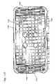
- FIGS. 24-30show the base 916 in isolation from the front cover 920 .
- the baseinclude integral hinge pins 1502 about which the hinge hooks 1500 of the cover 920 hook.
- the base 916is generally rectangular and defines an open interior in which fibers can be readily routed and managed.
- cable management spools 980are integrally formed with the base. In use, excess fiber or cable can be looped around the spools for cable management and/or storage. Hinge pins are provided at one side of the base while latch catches are provided at the opposite side of the base.
- FIGS. 115-121show an alternate embodiment of a base 1716 suitable for use with the enclosure 902 .
- the base 1716includes a base wall 1718 , a first wall 1720 , an oppositely disposed second wall 1722 , a first side 1724 , and an oppositely disposed second side 1726 .
- the base wall 1718 , the first and second walls 1720 , 1722 and the first and second sides 1724 , 1726cooperatively define an interior cavity 1728 .
- the first and second walls 1720 , 1722define a plurality of cable openings 1730 , through which cable enters and/or exits the enclosure 902 .
- the base 1716further includes a first inner wall 1732 and an oppositely disposed second inner wall 1734 .
- the first and second inner wallsare offset from the first and second walls 1720 , 1722 .
- the inserts 935 , 937are disposed between the first and second walls 1720 , 1722 and the first and second inner walls 1732 , 1734 , respectively.
- the base wall 1718includes a plurality of ridges 1736 .
- the plurality of ridges 1736is arranged in a waffle pattern on an inner surface of the base wall 1718 .
- the plurality of ridges 1736are adapted to provide strength to the base wall 1718 .
- An interior surface of the second side 1726 of the base 1716can include the pin cradles 1020 (best shown in FIG. 116 ), which are adapted to pivotally receive the pivot pins 1022 that are integral with the pivotal tray mount 960 .
- the pin cradles 1020are provided at the upper portion of the standoff 1026 that offsets the pin cradles 1020 from the bottom of the base 1716 .
- the integral hinge pins 1502are adapted to receive the hinge hooks 1500 of the cover 1620 .
- the plurality of integral hinge pins 1502extends substantially the entire length of the second side 1726 .
- the first side 1724 of the base 1716can include a latch receptacle 1740 .
- the latch receptacle 1740is adapted to receive the resilient latch 1568 of the tray mount 1561 .
- the latch receptacle 1740includes a latch opening 1742 disposed along its length. The latch opening 1742 is adapted to receive the lip 1576 of the latch portion 1574 of the resilient latch 1568 of the tray mount 1561 .
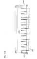
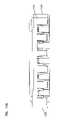
- FIGS. 54-56show the tray stack 949 in isolation from the enclosure 902 .
- the tray stack 949includes a hinging side 1070 positioned opposite from a latching side 1072 .
- each of the trays of the tray stack 949includes two dual pin components 1074 mounted at the hinging side 1070 .
- the dual pin components 1074have mounting posts 1076 that snap-fit within corresponding openings in the tray to mount the dual pin components 1074 to the trays.
- Each of the dual pin components 1074also includes two hinge pins 1078 .
- the trays of the tray stack 949are pivotally connected to one another by pivot linkages 1080 (see FIG. 54 and FIGS.
- the snap-fit receptacles 1082 of the pivot linkages 1080are snapped over the hinge pins 1078 of adjacent trays to provide pivotal connections between the adjacent trays.
- two of the hinge pins 1078are snapped within the hinge pin receivers 963 of the pivotal tray mount 960 .
- Fastenerscan also be used to non-pivotally secure the lowermost tray to the tray mount 960 .
- the latching side 1072 of the tray stack 949includes two dual pin components 1074 secured to the bottommost tray and two latching elements 1084 secured to each of the other trays.
- each of the latching components 1084includes mounting posts 1086 that are snap-fit within corresponding openings defined by the trays to secure the latching components 1084 to the trays.
- Each of the latching components 1084also includes a latching clip 1088 and a latching pin 1090 . When a given tray is pivoted to a closed position, the latching clips 1088 snap-fit over corresponding latching pins 1090 provided on the underlying tray to latch the tray in a closed position over the underlying tray.
- the latching clip 1088disengages from the latching pin 1090 to allow the tray to be moved to an open position.
- Two of the pins 1078 of the bottommost traysnap within snap-fit receptacles 1092 provided on cable management fingers 1094 (see FIGS. 67-71 ) that are attached to the base 916 .
- the pins 1078can be disengaged from the snap-fit receptacles 1092 to allow the bottommost tray to be pivoted to an open position where the interior region of the base 916 can be more fully accessed.
- the cable management finger 1094is generally L-shaped and includes a vertical leg 1096 and a horizontal leg 1098 .
- the vertical leg 1096includes a snap-fit member 1100 .
- the vertical legs 1096are secured within corresponding receptacles 1102 provided in the base 916 (e.g., by a snap-fit connection).
- the horizontal legs 1098function to assist in retaining fibers wrapped around the cable spooling region 1228 at the bottom of the base 916 so that the fibers do not interfere with the tray stack or move between the base 916 and the cover 920 .
- the wall box 900also includes further structure for mechanically securing the pass-through cable 933 or different types of cable such as drop cables to the enclosure 902 .
- a pass-through cable yoke 1320can be used to secure a pass-through cable 933 to the housing 902 .
- the pass-through cable yoke 130includes first and second clamping portions 1322 that cooperate to define a cable receiving opening 1324 .
- a pair of fastener receivers 1326extends vertically through the clamping portions 1322 . By inserting fasteners through the fastener receivers 1326 and into bosses 1328 (see FIGS.
- the fastenerscan be used to draw the clamping portions 1322 together such that a cable positioned within the cable receiving opening 1324 is clamped between the clamping portions 1322 and mechanically secured to the base 916 .
- FIG. 81shows a cross-sectional view of an example drop cable 1330 that may be routed through one of the cable exit/enter openings 932 .
- the drop cable 1330includes a central buffer tube 1332 containing one or more optical fibers.
- the drop cable 1330also includes strength members 1334 positioned on opposite side of the buffer tube 1330 and a jacket 1336 covering the strength members 1334 and the central buffer tube 1332 .
- FIG. 55shows a yoke 1338 configured to mechanically secure two of the drop cables 1330 to the enclosure.
- the yoke 1338has a multi-piece configuration including a middle piece 1340 and two end pieces 1342 .
- the middle piece 1340(shown at FIGS. 83-89 ) includes upper and lower surfaces defining clamping receptacles 1344 adapted to receive the drop cable 1330 .
- Clamping receptacles 1344are also defined in the surfaces of the end pieces 1342 (see FIGS. 90-96 ) that face toward the middle piece 1340 .
- the clamping receptacles 1344cooperate to define passages 1345 having an enlarged middle region 1346 and narrowed outer regions 1348 .
- the enlarged central regions 1346prevent central buffer tube 1332 of the drop cable 1330 from being crushed during clamping.
- the middle piece 1340 and end pieces 1342 of the yoke 1338are drawn together through the use of a fastener that extends through fastener receivers 1350 defined through the yoke 1338 .
- the yoke 1338is assembled with drop cables 1330 passing through the passages of the yoke. Fasteners are then inserted through the fastener openings and threaded into bosses 1328 (see FIGS. 24 and 25 ) provided at the bottom of the base 916 . As the fasteners are tightened, the pieces 1340 , 1342 of the yoke 1338 are drawn together to securely clamp the drop cables 1330 .
- reinforcing plates 1352may be provided at the top and bottom sides of the yokes 1338 , 1320 as shown at FIG. 55 . Moreover, if even further mechanical retention is required additional fasteners such as an additional strength member clamp 1354 (see FIG. 55 ) can be used to secure strength members of the cables to the enclosure 902 .
- additional cable management fingers 1560can be secured at various locations within the base 916 .
- the cable management fingers 1560have the same configuration as the cable management fingers 1094 except no snap-fit receptacle is provided on the horizontal leg. As shown at FIG. 13 , a plurality of the cable management fingers 1560 are shown snapped within the receptacles provided within the cable management spools 980 that are integrally formed with the base 916 .
- the cable management finger 1820is generally L-shaped and includes a vertical leg 1822 and a horizontal leg 1824 .
- the vertical leg 1820includes a first surface 1826 and an oppositely disposed second surface 1828 .
- a snap-fit member 1830is disposed on the second surface 1828 and is adapted to engage a complementary snap-fit member in the corresponding receptacles 1102 disposed around the cable spooling region 1228 provided in the base 916 .
- the first surface 1826 of the vertical leg 1822includes a protrusion 1832 that extends outwardly from the first surface 1826 .
- the protrusion 1832abuts a first face of the corresponding receptacle 1102 which keeps the first surface 1826 immediately adjacent to a second face, which is oppositely disposed from the first face, of the corresponding receptacle to assist in the engagement of the snap-fit member 1830 and the complementary snap-fit member.
- the vertical leg 1822is inserted into the corresponding receptacle 1102 of the cable spooling region 1228 and pushed into the receptacle 1102 .
- the vertical leg 1822is inserted until the snap-fit member 1830 engages the complementary snap-fit member in the receptacle 1102 .
- an end portion 1832 of the horizontal leg 1824is pushed toward the base 916 .
- the snap-fit member 1830 of the second surface 1828is disengaged from the complementary snap-fit member.
- the cable management finger 1820can be removed by pulling the vertical leg 1822 from the corresponding receptacle 11102 .
- FIGS. 97 and 98show an additional shroud or cover that can be mounted over the enclosure 902 to provide enhanced protection and to limit access to the exterior connectors.
- FIGS. 99 and 100show an alternative version where end covers are secured to the enclosure 902 to enclose the otherwise exposed portions of the fiber optic connectors.
- the wall box 1900is a rectangular-shaped enclosure 1901 having a base 1902 and a cover 1904 .
- a hinge assemblypivotally engages the base 1902 to the cover 1904 .
- the hinge assembly 1504includes a pin member 1506 and a hinge portion 1508 .
- the hinge assembly 1504includes multiple pin members 1506 and multiple hinge portions 1508 .
- the pin members 1506are disposed on one of the sides of the base 1902 and extend longitudinally along the side of the base 1902 while the hinge portions 1508 are disposed on one of the sides of the cover 1904 .
- the pin members 1506are generally cylindrical members.
- the pin members 1506extend between adjacent supports 1510 .
- the supports 1510generally support the pin members 1506 and are intermittently disposed along the length of the side of the base 1902 .
- the supports 1510are generally disposed such that the supports 1510 extend outwardly from the side of the base 1902 .
- the pin membersare disposed on the base 1902 such that there is a space disposed between the side of the base 1902 and the pin members 1506 . In the subject embodiment, this space is adapted to receive a portion of the hinge portions 1508 during installation and/or pivotal movement of the base 1902 and the cover 1904 .
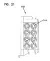
- Each of the hinge portions 1508includes a base end 1512 and an opposite free end 1514 .
- the base ends 1512 of the hinge portions 1508are mounted (e.g., fixed, bonded, fastened, molded, etc.) to one of the sides of the cover 1904 .
- the free ends 1514include hook portions 1516 having openings 1518 that are adapted to receive the pin members 1506 of the base 1902 .
- the cover 1904can pivot between an open position and a closed position with respect to the base 1902 .
- the cover 1904includes a retention member 1520 that is adapted to retain the pin member 1506 in the opening 1518 of the hook portion 1516 of the hinge portion 1508 .
- the retention member 1520is adapted to prevent or reduce the risk of inadvertent disengagement of the pin members 1506 and the hinge portions 1508 .
- the cover 1904includes two retention members 1520 .
- the retention member 1520is a resilient member that includes a body 1522 having a first end portion 1524 and a second end portion 1526 .
- the first end portion 1524is mounted between adjacent hinge portions 1508 on the cover 1904 at opposite ends of one of the sides of the cover 1904 .
- the second end portion 1526extends outwardly from the side of the cover 1904 such that the second end portion 1526 is generally aligned with the openings 1518 of the hinge portions 1508 .
- the pin members 1506are inserted into the openings 1518 .
- the pin members 1506contact an outer surface 1528 of the retention members 1520 .
- the retention members 1520flex inwardly toward the side of the cover 1904 to a flexed position.
- the retention members 1520snap back to a relaxed position such that the second end portions 1526 of the retention members 1520 block at least a portion of the openings 1518 and retain the pin members 1506 in the openings 1518 .
- an end surface 1530 of the second end portion 1526abuts one of the pin members 1506 to retain the pin members 1506 in the openings 1518 .
- the retention members 1520are manually flexed toward the side of the cover 1904 .
- the pin members 1506can be removed from the openings 1518 .
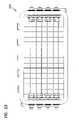
- the base 1902defines two sets of cable openings 1906 for allowing the telecommunications cable 933 to be routed through the enclosure 1901 .
- the sets of cable openings 1906are aligned along axes 1908 defining cable pass-through paths that extend through the enclosure 1901 .
- branch cablesexit the enclosure 1901 through the cable openings 1906 .
- Branch cablesare fiber optic cables having at least one optical fiber that is spliced to an optical fiber of the telecommunication cable 933 at the splice tray 1802 .
- the branch cablesare routed from the enclosure 1901 to a subscriber location or an intermediate access location. In order to seal these branch cables as they leave the enclosure, the branch cables are routed through grommets 1910 that are disposed in the cable exit/enter openings 1906 .
- Each grommet 1910includes a body 1912 having an outer surface 1914 and defining at least one cable bore 1916 through which the branch cable is routed.
- the body 1912defines two cable bores 1916 .
- the body 1912defines one cable bore 1916 .
- the outer surface 1914 of the body 1912includes a plurality of fins 1918 that extend outwardly from the outer surface 1914 .
- the plurality of fins 1918is generally parallel to an end surface 1920 of the grommet 1910 and extends around a portion of the circumference of the outer surface.
- the plurality of fins 1918 of the grommet 1910is adapted to be received in channels or grooves 1921 in the base 1902 .
- the disposition of the fins 1918 in the channels 1921prevents the grommet 1910 from being axially displaced in the cable opening 1906 and also increases a leakage path for fluid.
- the base 1902includes cable clamping areas 1922 disposed adjacent to the cable openings 1906 .
- Each cable clamping area 1922includes recess 1924 adapted to receive a fastener 1926 (shown in FIGS. 130 and 131 ).
- the recess 1924includes a first portion 1928 that is generally cylindrical in shape and a second portion 1930 .
- the second portion 1930includes sides that are not equidistant from the center of the second portion 1930 .
- the fastener 1926includes a first axial end portion 1932 and a second axial end portion 1934 .
- the first axial end portion 1932includes a first retention portion 1936 and a second retention portion 1938 .
- the first retention portion 1936is generally cylindrical in shape and is sized such that the outer diameter is slightly larger than the inner diameter of the first portion 1928 of the recess 1924 .
- an outer surface of the first retention portion 1936is texturized (e.g., knurled, etc.). The slightly larger outer diameter and the texturization of the outer surface of the first retention portion 1936 assists in the axial retention of the fastener 1926 in the recess 1924 .
- the second retention portion 1938includes sides having a plurality of points that are not equidistant from a center of the recess 1928 . By having sides that are not equidistant for the center of the recess 1924 , the second retention portion 1938 prevents the fastener 1926 from rotating about the center of the recess 1924 when installed.
- the second axial end portion 1934is adapted for engagement with a thru-hole of a cable clamping member.
- a plurality of threads disposed at the second axial end portion 1934is adapted for engagement with a nut that secures the cable clamping member to the base 1902 via the fastener 1926 thereby securing or clamping the telecommunications cable 933 in the cable openings 1906 .
- each of the cable clamping areas 1922includes an end wall 1950 .
- the end wall 1950includes an opening through which the buffer of the termination cable 933 passes. In one embodiment, the opening is smaller than the outer diameter of the jacket of the telecommunications cable 933 . By having an opening that is smaller than the outer diameter of the jacket of the telecommunications cable 933 , the end wall 1950 prevents the telecommunications cable 933 from being axially displaced or pushed inside the enclosure 1901 beyond the end wall 1950 .
- Each of the cable clamping areas 1922further includes a plurality of support walls 1952 .
- the support walls 1952prevent or reduce the risk of lateral (side-to-side) movement of the telecommunications cable 933 inside the enclosure 1901 .
- each of the support walls 1952extends outwardly from the cable clamping area 1922 in a direction that is generally parallel to the end wall 1950 .
- the support walls 1952are generally aligned with the recesses 1924 .
- the base 1902further includes a plurality of mounts 1954 adapted for engagement with pin members 1566 disposed on the tray mount 1561 .
- the tray mount 1561can pivot about an axis 1956 of the pin members 1566 between an open position (shown in FIG. 126 ) and a closed position (shown in FIG. 132 ).
- Each of the mounts 1954includes a slot 1958 (best shown in FIG. 126 ). With the tray mount 1561 in the open position, the pin members 1566 can be pushed into the slots 1958 until the pin members 1566 abut ends of the slots 1958 . With the pin members 1566 abutting the ends of the slots 1958 , an edge portion 1959 of the tray mount 1561 is disposed in the slot 1958 such that the tray mount 1561 is unable to pivot about the axis 1956 of the pin members 1566 .
- the tray mount 1561 with the splice tray stack 1800 disposed on the top surface 1570 and the splitter tray 1592 disposed on the bottom surface 1590 of the tray mountwould be pivoted about the axis 1956 of the pin members 1566 to the open position. In the open position, the splitter tray 1592 would be accessible. In order to prevent the tray mount 1561 from inadvertently being pivoted to the closed position, the pin members 1566 of the tray mount 1561 are pushed into the slot 1958 until the pin members 1566 abut the end of the slot 1958 .
- the tray mount 1561can be pivoted to the closed position by pulling the tray mount 1561 in a direction such that the pin members 1566 no longer abut the ends of the slots 1958 and the edge portion 1959 is no longer disposed in the slot 1958 . With the edge portion 1959 of the tray mount 1561 no longer disposed in the slot 1958 , the tray mount 1561 can be pivoted to the closed position. In this closed position, each of the slice trays 1802 of the splice tray stack 1800 can be accessed.
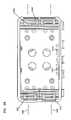
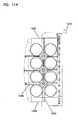
- the cover 1904includes a base wall 1960 having a cable management mounting area 1962 that is adapted for receiving a cable management tray 1964 and a plurality of sidewalls 1966 having a fanout mounting area 1968 adapted for receiving a fanout holder 1970 (shown in FIGS. 135 , 136 ).
- the cable management mounting area 1962 of the base wall 1960includes a plurality of mounting holes 1972 .
- the mounting holes 1972are adapted to receive fasteners 1974 that are disposed through holes 1976 in the cable management tray 1964 .
- the cable management mounting area 1962is disposed on a plurality of ridges 1978 that provide support to the base wall 1960 .
- the cable management tray 1964includes a center portion 1980 and a plurality of end portions 1982 .
- the center portion 1980includes ends that are generally semi-circular in shape while the end portions 1982 are generally quarter-moon shaped.
- the center portion 1980 and the end portions 1982cooperatively define a first fiber loop 1984 and a second fiber loop 1986 .
- the first fiber loop 1984is disposed interior to the second fiber loop 1986 .
- a plurality of retention fingers 1988extend partially across top of the first and second fiber loops 1984 , 1986 .
- optical fibers 1990are routed from fanouts 1992 disposed in the fanout holder 1970 to connectors 1994 disposed in the sidewalls 1966 of the cover through the first and/or second fiber loops 1984 , 1986 of the cable management tray 1964 .
- the fanout area 1968 on the sidewalls 1966includes a plurality of retention ribs 1996 and at least one latch opening 1998 .
- the retention ribs 1996are adapted to receive retention latches 2000 on the fanout holder 1970 in a sliding engagement while the latch opening 1998 is adapted to receive a resilient latch 2002 on the fanout holder 1970 in a snap-fit engagement.
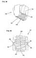
- the fanout holder 1970is shown.
- the fanout holder 1970is adapted to receive a plurality of fanouts.
- the fanout holder 1970is adapted to receive at least two fanouts.
- the fanout holder 1970is adapted to receive four fanouts.
- the fanout holder 1970includes a base 2004 having a front surface 2006 and an oppositely disposed rear surface 2008 .
- the fanout holder 1970is adapted to retain a plurality of fanouts.
- a plurality of retention members 2010 and a plurality of locators 2012retain the plurality of fanouts to the fanout holder 1970 .
- the plurality of retention members 2010extend outwardly from the front surface 2006 of the fanout holder 1970 .
- the retention members 2010are adapted to capture the fanouts disposed on the fanout holder 1970 .
- the retention members 2010are resilient latches having a latch end 2014 that is adapted to retain the plurality of fanouts to the holder.
- the plurality of locators 2012extends from the front surface 2006 of the fanout holder 1970 .
- the locators 2012are adapted to engage a receptacle in the fanout.
- the retention latches 2000include a base end 2016 that is attached to the rear surface 2008 and a free end 2018 .
- the free end 2018includes a lip 2020 and defines a channel 2022 between the lip 2020 and the rear surface 2008 of the fanout holder 1970 .
- Each channel 2022is adapted to engage one of the retention ribs 1996 of the fanout area 1968 of the cover 1904 .
- the engagement between the channels 2022 and the retention ribs 1996is sliding engagement.
- the resilient latch 2002includes a base portion 2024 and a free portion 2026 .
- the free portion 2026includes a lip 2028 that is adapted to engage the latch opening 1998 .
- the telecommunication cable 933enters the enclosure 1901 through the cable opening 1906 in the base 1902 .
- Optical fibers of the telecommunication cable 933are routed to the splice trays 1802 of the tray stack 1800 .
- the optical fibersare optically connected to an input fiber of the splitter.
- the input fiberis routed to the bottom surface 1590 of the tray mount 1561 to the splitter mounted on the splitter tray 1592 .
- Output fibersare routed from the splitter to the fanout mounted on the fanout holder 1970 .
- the output fibersare disposed in a ribbon cable that is disposed in a furcation tube. Upjacketed individual optical fibers having connectorized ends are then routed from the fanout to the inner ports of the fiber optic adapters 514 disposed on the cover 1904 and plugged into those inner ports.
- excess optical fibers between the fanout and the inner port of the fiber optic adapters 514are routed around the first and/or second loops 1984 , 1986 of the cable management tray 1964 .
Landscapes
- Physics & Mathematics (AREA)
- General Physics & Mathematics (AREA)
- Optics & Photonics (AREA)
- Light Guides In General And Applications Therefor (AREA)
- Cable Accessories (AREA)
Abstract
Description
Claims (19)
Priority Applications (7)
| Application Number | Priority Date | Filing Date | Title |
|---|---|---|---|
| US12/350,337US8111966B2 (en) | 2008-01-09 | 2009-01-08 | Wall box adapted to be mounted at a mid-span access location of a telecommunications cable |
| US13/367,100US8837894B2 (en) | 2008-01-09 | 2012-02-06 | Wall box adapted to be mounted at a mid-span access location of a telecommunications cable |
| US14/481,550US9557504B2 (en) | 2008-01-09 | 2014-09-09 | Wall box adapted to be mounted at a mid-span access location of a telecommunications cable |
| US15/414,094US10422970B2 (en) | 2008-01-09 | 2017-01-24 | Wall box adapted to be mounted at a mid-span access location of a telecommunications cable |
| US16/573,711US11036018B2 (en) | 2008-01-09 | 2019-09-17 | Wall box adapted to be mounted at a mid-span access location of a telecommunications cable |
| US17/344,232US11592636B2 (en) | 2008-01-09 | 2021-06-10 | Wall box adapted to be mounted at a mid-span access location of a telecommunications cable |
| US18/174,980US20230280562A1 (en) | 2008-01-09 | 2023-02-27 | Wall box adapted to be mounted at a mid-span access location of a telecommunications cable |
Applications Claiming Priority (6)
| Application Number | Priority Date | Filing Date | Title |
|---|---|---|---|
| US2010008P | 2008-01-09 | 2008-01-09 | |
| US2921408P | 2008-02-15 | 2008-02-15 | |
| US3904908P | 2008-03-24 | 2008-03-24 | |
| US4665608P | 2008-04-21 | 2008-04-21 | |
| US7735008P | 2008-07-01 | 2008-07-01 | |
| US12/350,337US8111966B2 (en) | 2008-01-09 | 2009-01-08 | Wall box adapted to be mounted at a mid-span access location of a telecommunications cable |
Related Child Applications (1)
| Application Number | Title | Priority Date | Filing Date |
|---|---|---|---|
| US13/367,100ContinuationUS8837894B2 (en) | 2008-01-09 | 2012-02-06 | Wall box adapted to be mounted at a mid-span access location of a telecommunications cable |
Publications (2)
| Publication Number | Publication Date |
|---|---|
| US20090238531A1 US20090238531A1 (en) | 2009-09-24 |
| US8111966B2true US8111966B2 (en) | 2012-02-07 |
Family
ID=40467319
Family Applications (7)
| Application Number | Title | Priority Date | Filing Date |
|---|---|---|---|
| US12/350,337Expired - Fee RelatedUS8111966B2 (en) | 2008-01-09 | 2009-01-08 | Wall box adapted to be mounted at a mid-span access location of a telecommunications cable |
| US13/367,100Expired - Fee RelatedUS8837894B2 (en) | 2008-01-09 | 2012-02-06 | Wall box adapted to be mounted at a mid-span access location of a telecommunications cable |
| US14/481,550Expired - Fee RelatedUS9557504B2 (en) | 2008-01-09 | 2014-09-09 | Wall box adapted to be mounted at a mid-span access location of a telecommunications cable |
| US15/414,094Active2029-11-10US10422970B2 (en) | 2008-01-09 | 2017-01-24 | Wall box adapted to be mounted at a mid-span access location of a telecommunications cable |
| US16/573,711Active2029-01-16US11036018B2 (en) | 2008-01-09 | 2019-09-17 | Wall box adapted to be mounted at a mid-span access location of a telecommunications cable |
| US17/344,232Active2029-01-30US11592636B2 (en) | 2008-01-09 | 2021-06-10 | Wall box adapted to be mounted at a mid-span access location of a telecommunications cable |
| US18/174,980AbandonedUS20230280562A1 (en) | 2008-01-09 | 2023-02-27 | Wall box adapted to be mounted at a mid-span access location of a telecommunications cable |
Family Applications After (6)
| Application Number | Title | Priority Date | Filing Date |
|---|---|---|---|
| US13/367,100Expired - Fee RelatedUS8837894B2 (en) | 2008-01-09 | 2012-02-06 | Wall box adapted to be mounted at a mid-span access location of a telecommunications cable |
| US14/481,550Expired - Fee RelatedUS9557504B2 (en) | 2008-01-09 | 2014-09-09 | Wall box adapted to be mounted at a mid-span access location of a telecommunications cable |
| US15/414,094Active2029-11-10US10422970B2 (en) | 2008-01-09 | 2017-01-24 | Wall box adapted to be mounted at a mid-span access location of a telecommunications cable |
| US16/573,711Active2029-01-16US11036018B2 (en) | 2008-01-09 | 2019-09-17 | Wall box adapted to be mounted at a mid-span access location of a telecommunications cable |
| US17/344,232Active2029-01-30US11592636B2 (en) | 2008-01-09 | 2021-06-10 | Wall box adapted to be mounted at a mid-span access location of a telecommunications cable |
| US18/174,980AbandonedUS20230280562A1 (en) | 2008-01-09 | 2023-02-27 | Wall box adapted to be mounted at a mid-span access location of a telecommunications cable |
Country Status (6)
| Country | Link |
|---|---|
| US (7) | US8111966B2 (en) |
| EP (1) | EP2238493A2 (en) |
| CN (1) | CN101965531B (en) |
| AU (1) | AU2009204170A1 (en) |
| BR (1) | BRPI0906796A2 (en) |
| WO (1) | WO2009089327A2 (en) |
Cited By (46)
| Publication number | Priority date | Publication date | Assignee | Title |
|---|---|---|---|---|
| US8494332B2 (en) | 2010-11-15 | 2013-07-23 | Adc Telecommunications, Inc. | Tray assembly for a fiber optic enclosure |
| US8837894B2 (en) | 2008-01-09 | 2014-09-16 | Adc Telecommunications, Inc. | Wall box adapted to be mounted at a mid-span access location of a telecommunications cable |
| US20140358070A1 (en) | 2007-04-13 | 2014-12-04 | Surgiquest, Inc. | System and method for improved gas recirculation in surgical trocars with pneumatic sealing |
| US20160018616A1 (en)* | 2014-07-15 | 2016-01-21 | Ofs Fitel, Llc | Drop cable assembly |
| US20170123176A1 (en)* | 2015-11-03 | 2017-05-04 | Raycap Intellectual Property Ltd. | Modular fiber optic cable splitter |
| US9696511B2 (en) | 2013-08-24 | 2017-07-04 | CommScope Connectivity Belgium BVBA | Sealing structures for optical cable closure |
| US10031307B2 (en) | 2014-04-03 | 2018-07-24 | CommScope Connectivity Belgium BVBA | Splitter module and enclosure for use therein |
| US10195371B2 (en) | 2005-02-15 | 2019-02-05 | Lexion Medical Llc | Trocar sleeve |
| US10209473B2 (en) | 2015-06-19 | 2019-02-19 | Commscope Technologies Llc | Optical termination enclosure |
| US10459172B1 (en)* | 2018-04-27 | 2019-10-29 | Hewlett Packard Enterprise Development Lp | Adapter retention mechanisms |
| US10509188B2 (en)* | 2014-09-30 | 2019-12-17 | CommScope Connectivity Belgium BVBA | System and method of fiber distribution |
| US10514519B2 (en) | 2016-01-14 | 2019-12-24 | Ppc Broadband, Inc. | Stackable splitters |
| US10663684B2 (en) | 2016-03-23 | 2020-05-26 | CommScope Connectivity Belgium BVBA | Module and enclosure for use therein |
| US10802237B2 (en) | 2015-11-03 | 2020-10-13 | Raycap S.A. | Fiber optic cable management system |
| US10812664B2 (en) | 2017-01-20 | 2020-10-20 | Raycap S.A. | Power transmission system for wireless communication systems |
| WO2021003544A1 (en)* | 2019-07-11 | 2021-01-14 | Furukawa Electric Latam S.A. | Optical branching and termination box |
| US10971928B2 (en) | 2018-08-28 | 2021-04-06 | Raycap Ip Assets Ltd | Integrated overvoltage protection and monitoring system |
| US11125961B2 (en)* | 2018-09-07 | 2021-09-21 | Go!Foton Holdings, Inc. | Optical fiber distribution system |
| USD935428S1 (en)* | 2019-04-19 | 2021-11-09 | Commscope Technologies Llc | Telecommunications identification plate |
| US11215768B2 (en) | 2017-06-28 | 2022-01-04 | Corning Research & Development Corporation | Fiber optic connectors and connectorization employing adhesive admitting adapters |
| US11251608B2 (en) | 2010-07-13 | 2022-02-15 | Raycap S.A. | Overvoltage protection system for wireless communication systems |
| US11294132B2 (en)* | 2017-12-12 | 2022-04-05 | Phoenix Contact Gmbh & Co. Kg | Splice distributor having a splice compartment |
| US11300746B2 (en) | 2017-06-28 | 2022-04-12 | Corning Research & Development Corporation | Fiber optic port module inserts, assemblies and methods of making the same |
| USD967050S1 (en) | 2018-10-19 | 2022-10-18 | Commscope Technologies Llc | Telecommunications enclosure |
| US11516327B2 (en) | 2018-05-01 | 2022-11-29 | Commscope Technologies Llc | Tray tower with position indexing trays |
| US11514821B2 (en) | 2017-11-28 | 2022-11-29 | Commscope Technologies Llc | Indicia and method for identifying telecommunications components |
| US11555975B2 (en) | 2018-03-29 | 2023-01-17 | Commscope Technologies Llc | Indicia and method for identifying telecommunications components |
| US11604320B2 (en) | 2020-09-30 | 2023-03-14 | Corning Research & Development Corporation | Connector assemblies for telecommunication enclosures |
| US20230090507A1 (en)* | 2020-02-11 | 2023-03-23 | Commscope Technologies Llc | Fiber management tray arrangements and assemblies for fiber optic closure organizers |
| US11650388B2 (en) | 2019-11-14 | 2023-05-16 | Corning Research & Development Corporation | Fiber optic networks having a self-supporting optical terminal and methods of installing the optical terminal |
| US11668890B2 (en) | 2017-06-28 | 2023-06-06 | Corning Research & Development Corporation | Multiports and other devices having optical connection ports with securing features and methods of making the same |
| US11677164B2 (en) | 2019-09-25 | 2023-06-13 | Raycap Ip Assets Ltd | Hybrid antenna distribution unit |
| US11686913B2 (en) | 2020-11-30 | 2023-06-27 | Corning Research & Development Corporation | Fiber optic cable assemblies and connector assemblies having a crimp ring and crimp body and methods of fabricating the same |
| US11703646B2 (en) | 2017-06-28 | 2023-07-18 | Corning Research & Development Corporation | Multiports and optical connectors with rotationally discrete locking and keying features |
| US20230280540A1 (en)* | 2022-03-03 | 2023-09-07 | Ppc Broadband, Inc. | Cable enclosure assembly having receiving area configured to alternatively receive cable retainer and cable adapter to allow plurality of configurations |
| US11880076B2 (en) | 2020-11-30 | 2024-01-23 | Corning Research & Development Corporation | Fiber optic adapter assemblies including a conversion housing and a release housing |
| US11886010B2 (en) | 2019-10-07 | 2024-01-30 | Corning Research & Development Corporation | Fiber optic terminals and fiber optic networks having variable ratio couplers |
| US11927810B2 (en) | 2020-11-30 | 2024-03-12 | Corning Research & Development Corporation | Fiber optic adapter assemblies including a conversion housing and a release member |
| US11947167B2 (en) | 2021-05-26 | 2024-04-02 | Corning Research & Development Corporation | Fiber optic terminals and tools and methods for adjusting a split ratio of a fiber optic terminal |
| US11994722B2 (en) | 2020-11-30 | 2024-05-28 | Corning Research & Development Corporation | Fiber optic adapter assemblies including an adapter housing and a locking housing |
| US12019279B2 (en) | 2019-05-31 | 2024-06-25 | Corning Research & Development Corporation | Multiports and other devices having optical connection ports with sliding actuators and methods of making the same |
| US12210203B2 (en) | 2019-03-29 | 2025-01-28 | Commscope Technologies Llc | Tray hinge interface system with opposing recessed surfaces recessed toward the pivot axis |
| US12237134B2 (en) | 2021-12-28 | 2025-02-25 | Raycap Ip Assets Ltd | Circuit protection for hybrid antenna distribution units |
| US12271040B2 (en) | 2017-06-28 | 2025-04-08 | Corning Research & Development Corporation | Fiber optic extender ports, assemblies and methods of making the same |
| US12298577B2 (en) | 2019-05-18 | 2025-05-13 | Commscope Technologies Llc | Telecommunications enclosure |
| US12372727B2 (en) | 2020-10-30 | 2025-07-29 | Corning Research & Development Corporation | Female fiber optic connectors having a rocker latch arm and methods of making the same |
Families Citing this family (131)
| Publication number | Priority date | Publication date | Assignee | Title |
|---|---|---|---|---|
| US8798427B2 (en) | 2007-09-05 | 2014-08-05 | Corning Cable Systems Llc | Fiber optic terminal assembly |
| CN101521545B (en)* | 2008-02-27 | 2012-10-10 | 3M创新有限公司 | High-density optical fiber distributing hub |
| US8718434B2 (en) | 2008-07-01 | 2014-05-06 | Adc Telecommunications, Inc. | Cable enclosure with sealed cable entry port |
| US8452148B2 (en) | 2008-08-29 | 2013-05-28 | Corning Cable Systems Llc | Independently translatable modules and fiber optic equipment trays in fiber optic equipment |
| US11294136B2 (en) | 2008-08-29 | 2022-04-05 | Corning Optical Communications LLC | High density and bandwidth fiber optic apparatuses and related equipment and methods |
| CN102209921B (en)* | 2008-10-09 | 2015-11-25 | 康宁光缆系统有限公司 | There is the fibre-optic terminus supported from the adapter panel of the input and output optical fiber of optical splitters |
| US8879882B2 (en) | 2008-10-27 | 2014-11-04 | Corning Cable Systems Llc | Variably configurable and modular local convergence point |
| US9036975B2 (en) | 2009-02-24 | 2015-05-19 | Adc Telecommunications, Inc. | Fiber optic cable pass-thru fitting |
| EP2221932B1 (en) | 2009-02-24 | 2011-11-16 | CCS Technology Inc. | Holding device for a cable or an assembly for use with a cable |
| WO2010102081A2 (en) | 2009-03-06 | 2010-09-10 | Adc Telecommunications, Inc. | Fiber optic cable pass-thru fitting |
| WO2010117656A2 (en)* | 2009-04-06 | 2010-10-14 | Adc Telecommunications, Inc. | Drop cable pass-thru fitting |
| US8699838B2 (en) | 2009-05-14 | 2014-04-15 | Ccs Technology, Inc. | Fiber optic furcation module |
| US8538226B2 (en) | 2009-05-21 | 2013-09-17 | Corning Cable Systems Llc | Fiber optic equipment guides and rails configured with stopping position(s), and related equipment and methods |
| US9075216B2 (en) | 2009-05-21 | 2015-07-07 | Corning Cable Systems Llc | Fiber optic housings configured to accommodate fiber optic modules/cassettes and fiber optic panels, and related components and methods |
| US8712206B2 (en) | 2009-06-19 | 2014-04-29 | Corning Cable Systems Llc | High-density fiber optic modules and module housings and related equipment |
| EP2443497B1 (en) | 2009-06-19 | 2020-03-04 | Corning Cable Systems LLC | High density and bandwidth fiber optic apparatus |
| US8929706B2 (en)* | 2009-08-31 | 2015-01-06 | Cisco Technology, Inc. | Fiber optic cable storage enclosure |
| US8180191B2 (en)* | 2009-10-23 | 2012-05-15 | Corning Cable Systems Llc | Mounting platforms for integrally supporting an optical splice tray(s) and/or an optical splitter(s) in a multi-port optical connection terminal and related methods |
| US8625950B2 (en) | 2009-12-18 | 2014-01-07 | Corning Cable Systems Llc | Rotary locking apparatus for fiber optic equipment trays and related methods |
| WO2011076275A1 (en)* | 2009-12-23 | 2011-06-30 | Prysmian S.P.A. | Optical termination assembly |
| US8992099B2 (en) | 2010-02-04 | 2015-03-31 | Corning Cable Systems Llc | Optical interface cards, assemblies, and related methods, suited for installation and use in antenna system equipment |
| DE102010010428B4 (en)* | 2010-03-05 | 2012-07-19 | Adc Gmbh | Connection box for fiber optic cable |
| US9547144B2 (en) | 2010-03-16 | 2017-01-17 | Corning Optical Communications LLC | Fiber optic distribution network for multiple dwelling units |
| US8913866B2 (en) | 2010-03-26 | 2014-12-16 | Corning Cable Systems Llc | Movable adapter panel |
| US8792767B2 (en)* | 2010-04-16 | 2014-07-29 | Ccs Technology, Inc. | Distribution device |
| CA2796221C (en) | 2010-04-16 | 2018-02-13 | Ccs Technology, Inc. | Sealing and strain relief device for data cables |
| EP2381284B1 (en) | 2010-04-23 | 2014-12-31 | CCS Technology Inc. | Under floor fiber optic distribution device |
| US9519118B2 (en) | 2010-04-30 | 2016-12-13 | Corning Optical Communications LLC | Removable fiber management sections for fiber optic housings, and related components and methods |
| US8705926B2 (en) | 2010-04-30 | 2014-04-22 | Corning Optical Communications LLC | Fiber optic housings having a removable top, and related components and methods |
| US20110268408A1 (en)* | 2010-04-30 | 2011-11-03 | Giraud William J | Door fiber management for fiber optic housings, and related components and methods |
| US9632270B2 (en) | 2010-04-30 | 2017-04-25 | Corning Optical Communications LLC | Fiber optic housings configured for tool-less assembly, and related components and methods |
| US8879881B2 (en) | 2010-04-30 | 2014-11-04 | Corning Cable Systems Llc | Rotatable routing guide and assembly |
| US9720195B2 (en) | 2010-04-30 | 2017-08-01 | Corning Optical Communications LLC | Apparatuses and related components and methods for attachment and release of fiber optic housings to and from an equipment rack |
| US8660397B2 (en) | 2010-04-30 | 2014-02-25 | Corning Cable Systems Llc | Multi-layer module |
| US9075217B2 (en) | 2010-04-30 | 2015-07-07 | Corning Cable Systems Llc | Apparatuses and related components and methods for expanding capacity of fiber optic housings |
| US8718436B2 (en) | 2010-08-30 | 2014-05-06 | Corning Cable Systems Llc | Methods, apparatuses for providing secure fiber optic connections |
| WO2012054454A2 (en) | 2010-10-19 | 2012-04-26 | Corning Cable Systems Llc | Transition box for multiple dwelling unit fiber optic distribution network |
| US9279951B2 (en) | 2010-10-27 | 2016-03-08 | Corning Cable Systems Llc | Fiber optic module for limited space applications having a partially sealed module sub-assembly |
| WO2012058391A1 (en) | 2010-10-28 | 2012-05-03 | Corning Cable Systems Llc | Impact resistant fiber optic enclosures and related methods |
| US8662760B2 (en) | 2010-10-29 | 2014-03-04 | Corning Cable Systems Llc | Fiber optic connector employing optical fiber guide member |
| US9116324B2 (en) | 2010-10-29 | 2015-08-25 | Corning Cable Systems Llc | Stacked fiber optic modules and fiber optic equipment configured to support stacked fiber optic modules |
| CA2819235C (en) | 2010-11-30 | 2018-01-16 | Corning Cable Systems Llc | Fiber device holder and strain relief device |
| GB201101749D0 (en)* | 2011-02-01 | 2011-03-16 | Hellermanntyton Data Ltd | Storage assembly for fibre-optic cables |
| WO2012106510A2 (en) | 2011-02-02 | 2012-08-09 | Corning Cable Systems Llc | Dense fiber optic connector assemblies and related connectors and cables suitable for establishing optical connections for optical backplanes in equipment racks |
| KR101253889B1 (en) | 2011-03-10 | 2013-04-16 | 이건테크놀로지 주식회사 | Terminal box for optical cable |
| US9008485B2 (en) | 2011-05-09 | 2015-04-14 | Corning Cable Systems Llc | Attachment mechanisms employed to attach a rear housing section to a fiber optic housing, and related assemblies and methods |
| AU2012275598A1 (en) | 2011-06-30 | 2014-01-16 | Corning Optical Communications LLC | Fiber optic equipment assemblies employing non-U-width-sized housings and related methods |
| US8953924B2 (en) | 2011-09-02 | 2015-02-10 | Corning Cable Systems Llc | Removable strain relief brackets for securing fiber optic cables and/or optical fibers to fiber optic equipment, and related assemblies and methods |
| US9069151B2 (en) | 2011-10-26 | 2015-06-30 | Corning Cable Systems Llc | Composite cable breakout assembly |
| US9038832B2 (en) | 2011-11-30 | 2015-05-26 | Corning Cable Systems Llc | Adapter panel support assembly |
| US9219546B2 (en) | 2011-12-12 | 2015-12-22 | Corning Optical Communications LLC | Extremely high frequency (EHF) distributed antenna systems, and related components and methods |
| US10110307B2 (en) | 2012-03-02 | 2018-10-23 | Corning Optical Communications LLC | Optical network units (ONUs) for high bandwidth connectivity, and related components and methods |
| US9791653B2 (en)* | 2012-04-03 | 2017-10-17 | CommScope Connectivity Belgium BVBA | Telecommunications enclosure organizer |
| US8873926B2 (en) | 2012-04-26 | 2014-10-28 | Corning Cable Systems Llc | Fiber optic enclosures employing clamping assemblies for strain relief of cables, and related assemblies and methods |
| US9004778B2 (en) | 2012-06-29 | 2015-04-14 | Corning Cable Systems Llc | Indexable optical fiber connectors and optical fiber connector arrays |
| US9250409B2 (en) | 2012-07-02 | 2016-02-02 | Corning Cable Systems Llc | Fiber-optic-module trays and drawers for fiber-optic equipment |
| US20140020927A1 (en)* | 2012-07-18 | 2014-01-23 | Checkers Industrial Products, Llc | Cable protector lid connection systems and methods |
| US9049500B2 (en) | 2012-08-31 | 2015-06-02 | Corning Cable Systems Llc | Fiber optic terminals, systems, and methods for network service management |
| US9042702B2 (en) | 2012-09-18 | 2015-05-26 | Corning Cable Systems Llc | Platforms and systems for fiber optic cable attachment |
| US8909019B2 (en) | 2012-10-11 | 2014-12-09 | Ccs Technology, Inc. | System comprising a plurality of distribution devices and distribution device |
| ES2551077T3 (en) | 2012-10-26 | 2015-11-16 | Ccs Technology, Inc. | Fiber optic management unit and fiber optic distribution device |
| US20140219621A1 (en)* | 2013-02-06 | 2014-08-07 | Corning Cable Systems Llc | Fiber optic multiport |
| US20150268434A1 (en)* | 2013-02-06 | 2015-09-24 | Corning Optical Communications LLC | Fiber optic multiport |
| US8998504B2 (en)* | 2013-02-21 | 2015-04-07 | Avago Technologies General Ip (Singapore) Pte. Ltd. | User-configurable optical fiber link |
| US8985862B2 (en) | 2013-02-28 | 2015-03-24 | Corning Cable Systems Llc | High-density multi-fiber adapter housings |
| US9535226B2 (en)* | 2013-03-29 | 2017-01-03 | 3M Innovative Properties Company | Modular breakout device for optical and electrical connections |
| CN105324697A (en)* | 2013-05-21 | 2016-02-10 | 康宁光电通信有限责任公司 | Optical cable splice cassettes with hingedly attached device holder |
| WO2014196699A1 (en)* | 2013-06-03 | 2014-12-11 | Im Chae Hyeon | Multilayered optical core wire storage chest |
| US9829668B2 (en) | 2013-08-23 | 2017-11-28 | CommScope Connectivity Belgium BVBA | Pass-through assembly having an anchor member and a cover |
| EP3132298B1 (en) | 2014-04-14 | 2021-08-11 | CommScope Connectivity Belgium BVBA | Fiber optic enclosure with cable management drawer |
| US9766414B2 (en)* | 2014-06-27 | 2017-09-19 | Commscope Technologies Llc | Indexing terminals for supporting a bidirectional indexing architecture |
| WO2016007488A1 (en)* | 2014-07-10 | 2016-01-14 | Corning Optical Communications LLC | Optical fiber distribution hub with fiber routing structures |
| KR101718968B1 (en) | 2014-09-22 | 2017-03-22 | 임채현 | Optical fiber box |
| US10509187B2 (en) | 2014-09-23 | 2019-12-17 | Ppc Broadband, Inc. | Universal multi-purpose compartmentalized telecommunications box |
| US10976512B2 (en)* | 2014-09-23 | 2021-04-13 | Ppc Broadband, Inc. | House box with mounting surface for mounted access |
| WO2016049242A1 (en) | 2014-09-23 | 2016-03-31 | Ppc Broadband, Inc. | Universal multi-purpose compartmentalized telecommunications box |
| WO2016066779A1 (en)* | 2014-10-31 | 2016-05-06 | Tyco Electronics Raychem Bvba | Hinge lock device and method |
| EP3215882B1 (en) | 2014-11-04 | 2020-01-15 | CommScope Connectivity Belgium BVBA | Enclosure for use in a fiber optic distribution network |
| JP6584081B2 (en)* | 2015-02-09 | 2019-10-02 | 湖北工業株式会社 | Optical device housing and optical device unit |
| US9494760B2 (en) | 2015-02-17 | 2016-11-15 | 3M Innovative Properties Company | Highly configurable fiber-optic interconnection tray |
| US10031306B2 (en)* | 2015-02-27 | 2018-07-24 | Opterna Technology Limited | Fiber distribution assemblies |
| FR3038072B1 (en)* | 2015-06-24 | 2018-11-09 | Nexans | OPTICAL FIBER CONNECTION HOUSING |
| EP3128353A1 (en)* | 2015-08-07 | 2017-02-08 | CCS Technology Inc. | Cable grommet and fiber optic distribution device |
| US10371913B2 (en)* | 2015-09-16 | 2019-08-06 | CommScope Connectivity Begium BVBA | Splitter module and enclosure for use therein |
| US10274691B2 (en) | 2015-11-06 | 2019-04-30 | CommScope Connectivity Belgium BVBA | Clamping device |
| US10663688B2 (en)* | 2016-04-28 | 2020-05-26 | Channell Commerical Corporation | Stubbed terminal housing for communications vault or pedestal |
| CN105929512A (en)* | 2016-07-11 | 2016-09-07 | 上海博中机电科技有限公司 | Branch module type prefabricated optical cable |
| US11073670B2 (en) | 2016-08-12 | 2021-07-27 | Corning Optical Communications LLC | Device and method for sealing multiport splitters |
| US10606006B2 (en)* | 2016-09-20 | 2020-03-31 | Clearfield, Inc. | Optical fiber distribution systems and components |
| US10859781B2 (en) | 2016-09-20 | 2020-12-08 | Clearfield, Inc. | Optical fiber distribution systems and components |
| CN206147157U (en) | 2016-11-15 | 2017-05-03 | 浙江超前通信设备有限公司 | Optical Splice Closure |
| BR102016029000B1 (en)* | 2016-12-09 | 2022-09-13 | Furukawa Industrial S.A. Produtos Elétricos | OPTICAL TERMINATION BOX |
| US10790899B2 (en) | 2017-01-12 | 2020-09-29 | Commscope Technologies Llc | Optical tapping in an indexing architecture |
| EP3583455A1 (en)* | 2017-02-15 | 2019-12-25 | CommScope Connectivity Belgium BVBA | Interchangeable telecommunications enclosure components |
| WO2018204864A1 (en) | 2017-05-04 | 2018-11-08 | Go!Foton Holding, Inc. | Cable termination assembly |
| US10353164B2 (en)* | 2017-06-27 | 2019-07-16 | Afl Telecommunications Llc | Fiber optic transition assemblies |
| US11187859B2 (en) | 2017-06-28 | 2021-11-30 | Corning Research & Development Corporation | Fiber optic connectors and methods of making the same |
| KR102208460B1 (en) | 2017-09-07 | 2021-01-27 | 임채현 | Optical fiber box |
| US10684426B2 (en) | 2017-09-08 | 2020-06-16 | Commscope Technologies Llc | Telecommunication enclosures |
| EP3698192A4 (en)* | 2017-10-17 | 2021-09-22 | Corning Research And Development Corporation | HOUSING FOR SPLICE OF OPTICAL FIBERS |
| US10578823B2 (en) | 2017-12-28 | 2020-03-03 | Afl Ig Llc | Wall cabinets and fiber management trays |
| US11428886B2 (en) | 2018-04-23 | 2022-08-30 | Commscope Technologies, Inc. | Mounting bracket system for telecommunications equipment |
| US11280976B2 (en) | 2018-05-11 | 2022-03-22 | Ppc Broadband Fiber Ltd. | Fiber splice closure having a raised deck covering a splitter |
| US11695260B2 (en) | 2018-06-12 | 2023-07-04 | Commscope Technologies Llc | Telecommunications enclosure with a separate mountable hinge |
| US12169318B2 (en) | 2018-08-20 | 2024-12-17 | Commscope Technologies Llc | Telecommunications equipment frame |
| US11703651B2 (en) | 2018-11-02 | 2023-07-18 | Go!Foton Holdings, Inc. | Cable termination assembly with disengagement prevention structures |
| US10641967B1 (en) | 2018-11-16 | 2020-05-05 | Corning Research & Development Corporation | Multiport assemblies including a modular adapter support array |
| US11531170B2 (en) | 2018-11-28 | 2022-12-20 | Go!Foton Holdings, Inc. | Intelligent patch panel |
| US10768382B2 (en) | 2018-11-29 | 2020-09-08 | Corning Research & Development Corporation | Multiport assemblies including access apertures and a release tool |
| PT3903136T (en) | 2018-12-28 | 2024-12-05 | Corning Res & Dev Corp | Multiport assemblies including mounting features or dust plugs |
| EP3912364B1 (en)* | 2019-01-15 | 2023-12-13 | CommScope Technologies LLC | Tray hinge system |
| IT201900000915A1 (en)* | 2019-01-22 | 2020-07-22 | Prysmian Spa | OUTDOOR OPTICAL JUNCTION BOX |
| WO2020154408A1 (en) | 2019-01-22 | 2020-07-30 | Commscope Technologies Llc | Telecommunication enclosure |
| WO2020167639A1 (en) | 2019-02-11 | 2020-08-20 | Commscope Technologies Llc | Splice closure |
| WO2020242981A1 (en)* | 2019-05-24 | 2020-12-03 | Commscope Technologies Llc | Sealed closure with space management features |
| WO2021011541A1 (en)* | 2019-07-15 | 2021-01-21 | Commscope Technologies Llc | Telecommunications tray assembly |
| US11294133B2 (en) | 2019-07-31 | 2022-04-05 | Corning Research & Development Corporation | Fiber optic networks using multiports and cable assemblies with cable-to-connector orientation |
| US11487073B2 (en) | 2019-09-30 | 2022-11-01 | Corning Research & Development Corporation | Cable input devices having an integrated locking feature and assemblies using the cable input devices |
| EP4055431A4 (en) | 2019-11-07 | 2023-11-29 | CommScope Technologies LLC | Telecommunications enclosure mounting system |
| BR102019023385A2 (en)* | 2019-11-07 | 2021-05-18 | Furukawa Electric Latam S.A. | termination box and optical branch |
| CN110927902B (en)* | 2019-11-26 | 2021-02-02 | 烽火海洋网络设备有限公司 | Submarine remote pumping optical amplifier packaging structure |
| WO2021150601A1 (en)* | 2020-01-21 | 2021-07-29 | Commscope Technologies Llc | Latching system unitarily molded with a re-enterable enclosure |
| US11536921B2 (en) | 2020-02-11 | 2022-12-27 | Corning Research & Development Corporation | Fiber optic terminals having one or more loopback assemblies |
| EP4158406A4 (en)* | 2020-05-29 | 2024-07-17 | CommScope Technologies LLC | FIBER MANAGEMENT TRAY ASSEMBLY AND FIBER OPTIC LOCKING ORGANISER ASSEMBLY |
| CN111538127B (en)* | 2020-06-05 | 2024-09-20 | 义博通信设备集团股份有限公司 | Spliced optical splitter and mounting method thereof |
| CN111983755B (en)* | 2020-06-22 | 2022-11-11 | 中国铁路通信信号上海工程局集团有限公司 | Longitudinal cutting and splicing method for optical cable bundle tube |
| WO2022032130A1 (en) | 2020-08-07 | 2022-02-10 | Commscope Technologies Llc | Adjustable cable management system |
| US12253732B2 (en)* | 2021-06-23 | 2025-03-18 | Corning Research & Development Corporation | Fiber optic assembly with splice tray |
| EP4449179A1 (en)* | 2021-12-17 | 2024-10-23 | CommScope Technologies LLC | Fiber management tray assemblies and methods for improved fiber management versatility in telecommunications closures |
| US20230408784A1 (en)* | 2022-06-17 | 2023-12-21 | Commscope Technologies Llc | Connection interfaces and related assemblies |
| US20250060549A1 (en)* | 2023-08-18 | 2025-02-20 | Ppc Broadband, Inc. | Compact distribution enclosure configured to provide enhanced connectivity and access to an interior of the enclosure |
Citations (49)
| Publication number | Priority date | Publication date | Assignee | Title |
|---|---|---|---|---|
| US4805979A (en) | 1987-09-04 | 1989-02-21 | Minnesota Mining And Manufacturing Company | Fiber optic cable splice closure |
| DE3825756C1 (en) | 1988-07-29 | 1989-09-21 | Walter Rose Gmbh & Co Kg, 5800 Hagen, De | |
| US5080459A (en) | 1987-12-23 | 1992-01-14 | British Telecommunications Public Limited Company | Mounting assembly for optical equipment |
| US5133039A (en) | 1990-10-29 | 1992-07-21 | At&T Bell Laboratories | Aerial fiber optic cable case |
| US5313546A (en) | 1991-11-29 | 1994-05-17 | Sirti, S.P.A. | Hermetically sealed joint cover for fibre optic cables |
| EP0637767A2 (en) | 1993-07-08 | 1995-02-08 | WALTER ROSE GmbH & Co. KG | An enclosure for multifilament cables |
| US5479533A (en) | 1992-02-28 | 1995-12-26 | Yamatake-Honeywell Co., Ltd. | Pattern recognition apparatus and method using fuzzy logic |
| US5495549A (en) | 1994-02-18 | 1996-02-27 | Keptel, Inc. | Optical fiber splice closure |
| US5631993A (en) | 1995-04-20 | 1997-05-20 | Preformed Line Products Company | Optical fiber splice case |
| US5652820A (en) | 1995-11-13 | 1997-07-29 | Act Communications, Inc. | Fiber optic splice closure and protection apparatus |
| US5668911A (en)* | 1996-07-11 | 1997-09-16 | Northern Telecom Limited | Storage holders for optical fibers |
| EP0797114A2 (en) | 1996-03-20 | 1997-09-24 | RXS Kabelgarnituren Gesellschaft mit beschränkter Haftung | Cable sleeve |
| US5692299A (en) | 1993-04-19 | 1997-12-02 | Raychem Corporation | Fiber optic splice closure and associated methods |
| WO1998008125A2 (en) | 1996-08-22 | 1998-02-26 | N.V. Raychem S.A. | Optical fibre splice closure |
| US5754723A (en)* | 1993-07-08 | 1998-05-19 | Raychem Gmbh | Multi-filament splice enclosures |
| US5754724A (en)* | 1996-11-08 | 1998-05-19 | Antec Corporation | Fiber optic support apparatus |
| US5778122A (en) | 1996-12-24 | 1998-07-07 | Siecor Corporation | Fiber optic cable assembly for interconnecting optical fibers within a receptacle mounted within the wall of an enclosure |
| US5790741A (en) | 1995-05-24 | 1998-08-04 | Alcatel Cable Interface | Optical fiber splice tray |
| US5790739A (en) | 1995-12-21 | 1998-08-04 | Siecor Corporation | Optical fiber interconnect and canister closure assembly |
| US5825964A (en) | 1995-06-23 | 1998-10-20 | Preformed Line Products Company | Optical fiber splice case with cross connect feature |
| US5862290A (en) | 1997-05-01 | 1999-01-19 | Lucent Technologies Inc. | Optical fiber cable splice closure |
| US5982972A (en)* | 1996-04-30 | 1999-11-09 | Next Level Communications | Line card for optical network unit mechanical enclosure |
| US5982870A (en) | 1992-05-26 | 1999-11-09 | Bell Atlantic Network Services, Inc. | Method for concurrently establishing switch redirection for multiple lines of the public telephone network |
| US6152767A (en) | 1996-01-24 | 2000-11-28 | N.V. Raychem S.A. | Cable closure |
| US6175079B1 (en) | 1999-06-03 | 2001-01-16 | Tyco Electronics Corporation | Fiber optic cable management system |
| US6226434B1 (en)* | 1996-05-14 | 2001-05-01 | Japan Recom Ltd. | Closure for cable connection |
| US6249632B1 (en) | 1998-11-12 | 2001-06-19 | Wittmeier, Ii David Arthur | Fiber optic splice closure including end pivoting slack storage holder and associated methods |
| US6275640B1 (en) | 1999-04-21 | 2001-08-14 | Tyco Electrtonics Corporation | Fiber optic splice closure including end pivoting slack storage holder with adjustable rear wall and associated methods |
| GB2367379A (en) | 2000-09-27 | 2002-04-03 | Krone Gmbh | Fibre optic organiser mounted to a wall |
| EP1203974A2 (en) | 2000-11-01 | 2002-05-08 | Tyco Electronics Corporation | Low profile optical fibre network interface enclosure |
| US6411767B1 (en) | 1999-08-24 | 2002-06-25 | Corning Cable Systems Llc | Optical fiber interconnection closures |
| US6483977B2 (en) | 2001-04-12 | 2002-11-19 | Corning Cable Systems Llc | Fiber management frame having movable work platform |
| US6507691B1 (en) | 1999-03-22 | 2003-01-14 | Tyco Electronics Corporation | Fiber optic splice organizer with splicing tray and associated method |
| US6539160B2 (en) | 2000-10-27 | 2003-03-25 | Corning Cable Systems Llc | Optical fiber splicing and connecting assembly with coupler cassette |
| US6542688B1 (en) | 2000-10-27 | 2003-04-01 | Corning Cable Systems Llc | Optical fiber splicing and connecting assembly |
| US20030103750A1 (en)* | 2001-11-30 | 2003-06-05 | Laporte Richard B. | Distribution terminal for network access point |
| US20040001686A1 (en)* | 2002-06-28 | 2004-01-01 | Smith Kelly J. | Aerial closure for local convergence point |
| US6721484B1 (en)* | 2002-09-27 | 2004-04-13 | Corning Cable Systems Llc | Fiber optic network interface device |
| US6797878B1 (en) | 1999-04-26 | 2004-09-28 | Tyco Electronics Raychem Nv | Closure casing |
| US6798967B2 (en) | 2001-04-12 | 2004-09-28 | Corning Cable Systems Llc | Fiber management frame for securely retaining optical fiber connection trays |
| US6856748B1 (en) | 2003-09-30 | 2005-02-15 | Corning Cable Systems Llc | Interconnection enclosure having a connector port and preterminated optical connector |
| US6926449B1 (en) | 2004-02-23 | 2005-08-09 | Corning Cable Systems Llc | Connector port for network interface device |
| US20050175307A1 (en)* | 2004-02-06 | 2005-08-11 | Battey Jennifer A. | Optical connection closure having at least one connector port |
| US20050271344A1 (en)* | 2004-05-11 | 2005-12-08 | Grubish Christopher S | Convertible fiber closure platform |
| US20060083475A1 (en) | 2003-10-06 | 2006-04-20 | Christopher Grubish | Optical fiber splice case |
| EP1832907A1 (en) | 2006-03-10 | 2007-09-12 | Ictl | Wired element coiling box assembly |
| EP1870750A2 (en) | 2006-06-22 | 2007-12-26 | Nexans | Cassette for optical cables, support rail and assembly for stacking such cassettes |
| US7359611B1 (en)* | 2007-02-23 | 2008-04-15 | Multilink, Inc. | Slack cable storage box with adjustable height spools |
| US20090202214A1 (en)* | 2007-12-11 | 2009-08-13 | Adc Telecommuniactions, Inc. | Wall box adapted to be mounted at a mid-span access location of a telecommunications cable |
Family Cites Families (14)
| Publication number | Priority date | Publication date | Assignee | Title |
|---|---|---|---|---|
| ES2117068T3 (en)* | 1992-07-17 | 1998-08-01 | Rxs Schrumpftech Garnituren | DEVICE FOR POSITIONING FIBER OPTIC CONNECTING BOXES INSIDE A CABLE SLEEVE. |
| US5274731A (en)* | 1992-12-24 | 1993-12-28 | Adc Telecommunications, Inc. | Optical fiber cabinet |
| US5892870A (en)* | 1995-11-16 | 1999-04-06 | Fiber Connections Inc. | Fibre optic cable connector |
| TW419152U (en)* | 1999-05-15 | 2001-01-11 | Hon Hai Prec Ind Co Ltd | Electrical connector |
| US6385381B1 (en) | 1999-09-21 | 2002-05-07 | Lucent Technologies Inc. | Fiber optic interconnection combination closure |
| US7220144B1 (en) | 2000-02-01 | 2007-05-22 | Adc Telecommunications, Inc. | Multimedia outlet box |
| US6788786B1 (en) | 2000-09-22 | 2004-09-07 | Adc Telecommunications, Inc. | Multimedia patching box |
| US7142764B2 (en)* | 2003-03-20 | 2006-11-28 | Tyco Electronics Corporation | Optical fiber interconnect cabinets, termination modules and fiber connectivity management for the same |
| US7477826B2 (en)* | 2007-01-16 | 2009-01-13 | Tyco Electronics Corporation | Cable enclosure assemblies and methods for using the same |
| US7493003B2 (en) | 2007-05-07 | 2009-02-17 | Adc Telecommunications, Inc. | Modular optical wall box enclosure |
| US8220652B2 (en)* | 2007-07-31 | 2012-07-17 | Rgb Systems, Inc. | Power supply support system |
| WO2009089327A2 (en) | 2008-01-09 | 2009-07-16 | Adc Telecommunications, Inc. | Wall box adapted to be mounted at a mid-span access location of a telecommunications cable |
| US8471145B2 (en)* | 2008-07-14 | 2013-06-25 | Mitsubishi Electric Corporation | Terminal box and solar cell module |
| EP2443497B1 (en)* | 2009-06-19 | 2020-03-04 | Corning Cable Systems LLC | High density and bandwidth fiber optic apparatus |
- 2009
- 2009-01-08WOPCT/US2009/030414patent/WO2009089327A2/enactiveApplication Filing
- 2009-01-08AUAU2009204170Apatent/AU2009204170A1/ennot_activeAbandoned
- 2009-01-08USUS12/350,337patent/US8111966B2/ennot_activeExpired - Fee Related
- 2009-01-08BRBRPI0906796-5Apatent/BRPI0906796A2/ennot_activeIP Right Cessation
- 2009-01-08EPEP09701175Apatent/EP2238493A2/ennot_activeWithdrawn
- 2009-01-08CNCN200980108160.5Apatent/CN101965531B/ennot_activeExpired - Fee Related
- 2012
- 2012-02-06USUS13/367,100patent/US8837894B2/ennot_activeExpired - Fee Related
- 2014
- 2014-09-09USUS14/481,550patent/US9557504B2/ennot_activeExpired - Fee Related
- 2017
- 2017-01-24USUS15/414,094patent/US10422970B2/enactiveActive
- 2019
- 2019-09-17USUS16/573,711patent/US11036018B2/enactiveActive
- 2021
- 2021-06-10USUS17/344,232patent/US11592636B2/enactiveActive
- 2023
- 2023-02-27USUS18/174,980patent/US20230280562A1/ennot_activeAbandoned
Patent Citations (61)
| Publication number | Priority date | Publication date | Assignee | Title |
|---|---|---|---|---|
| US4805979A (en) | 1987-09-04 | 1989-02-21 | Minnesota Mining And Manufacturing Company | Fiber optic cable splice closure |
| US5080459A (en) | 1987-12-23 | 1992-01-14 | British Telecommunications Public Limited Company | Mounting assembly for optical equipment |
| DE3825756C1 (en) | 1988-07-29 | 1989-09-21 | Walter Rose Gmbh & Co Kg, 5800 Hagen, De | |
| US5133039A (en) | 1990-10-29 | 1992-07-21 | At&T Bell Laboratories | Aerial fiber optic cable case |
| US5313546A (en) | 1991-11-29 | 1994-05-17 | Sirti, S.P.A. | Hermetically sealed joint cover for fibre optic cables |
| US5479533A (en) | 1992-02-28 | 1995-12-26 | Yamatake-Honeywell Co., Ltd. | Pattern recognition apparatus and method using fuzzy logic |
| US5982870A (en) | 1992-05-26 | 1999-11-09 | Bell Atlantic Network Services, Inc. | Method for concurrently establishing switch redirection for multiple lines of the public telephone network |
| US5692299A (en) | 1993-04-19 | 1997-12-02 | Raychem Corporation | Fiber optic splice closure and associated methods |
| EP0637767A2 (en) | 1993-07-08 | 1995-02-08 | WALTER ROSE GmbH & Co. KG | An enclosure for multifilament cables |
| US5754723A (en)* | 1993-07-08 | 1998-05-19 | Raychem Gmbh | Multi-filament splice enclosures |
| US5495549A (en) | 1994-02-18 | 1996-02-27 | Keptel, Inc. | Optical fiber splice closure |
| US5790740A (en) | 1995-04-20 | 1998-08-04 | Preformed Line Products Company | Optical fiber splice case |
| US5884001A (en) | 1995-04-20 | 1999-03-16 | Preformed Line Products Company | Cable splice enclosure with cable storage trays and cable splice trays |
| US5883999A (en) | 1995-04-20 | 1999-03-16 | Preformed Line Products Company | Optical fiber splice case |
| US5631993A (en) | 1995-04-20 | 1997-05-20 | Preformed Line Products Company | Optical fiber splice case |
| US5884002A (en) | 1995-04-20 | 1999-03-16 | Preformed Line Products Company | Cable splice enclosure system with interchangeable outer housing sizes |
| US5884003A (en) | 1995-04-20 | 1999-03-16 | Preformed Line Products Company | Cable splice enclosure with strap member holding stacked splice trays |
| US5790741A (en) | 1995-05-24 | 1998-08-04 | Alcatel Cable Interface | Optical fiber splice tray |
| US5825964A (en) | 1995-06-23 | 1998-10-20 | Preformed Line Products Company | Optical fiber splice case with cross connect feature |
| US5652820A (en) | 1995-11-13 | 1997-07-29 | Act Communications, Inc. | Fiber optic splice closure and protection apparatus |
| US5790739A (en) | 1995-12-21 | 1998-08-04 | Siecor Corporation | Optical fiber interconnect and canister closure assembly |
| US6152767A (en) | 1996-01-24 | 2000-11-28 | N.V. Raychem S.A. | Cable closure |
| EP0797114A2 (en) | 1996-03-20 | 1997-09-24 | RXS Kabelgarnituren Gesellschaft mit beschränkter Haftung | Cable sleeve |
| US5787219A (en)* | 1996-03-20 | 1998-07-28 | Siemens Aktiengesellschaft | Cable closure |
| US5982972A (en)* | 1996-04-30 | 1999-11-09 | Next Level Communications | Line card for optical network unit mechanical enclosure |
| US6226434B1 (en)* | 1996-05-14 | 2001-05-01 | Japan Recom Ltd. | Closure for cable connection |
| US5668911A (en)* | 1996-07-11 | 1997-09-16 | Northern Telecom Limited | Storage holders for optical fibers |
| US6275639B1 (en) | 1996-08-22 | 2001-08-14 | Sidney Joseph Bolt | Optical fiber splice closure |
| WO1998008125A2 (en) | 1996-08-22 | 1998-02-26 | N.V. Raychem S.A. | Optical fibre splice closure |
| US5754724A (en)* | 1996-11-08 | 1998-05-19 | Antec Corporation | Fiber optic support apparatus |
| US5778122A (en) | 1996-12-24 | 1998-07-07 | Siecor Corporation | Fiber optic cable assembly for interconnecting optical fibers within a receptacle mounted within the wall of an enclosure |
| US5862290A (en) | 1997-05-01 | 1999-01-19 | Lucent Technologies Inc. | Optical fiber cable splice closure |
| US6249632B1 (en) | 1998-11-12 | 2001-06-19 | Wittmeier, Ii David Arthur | Fiber optic splice closure including end pivoting slack storage holder and associated methods |
| US6507691B1 (en) | 1999-03-22 | 2003-01-14 | Tyco Electronics Corporation | Fiber optic splice organizer with splicing tray and associated method |
| US6275640B1 (en) | 1999-04-21 | 2001-08-14 | Tyco Electrtonics Corporation | Fiber optic splice closure including end pivoting slack storage holder with adjustable rear wall and associated methods |
| US6797878B1 (en) | 1999-04-26 | 2004-09-28 | Tyco Electronics Raychem Nv | Closure casing |
| US6175079B1 (en) | 1999-06-03 | 2001-01-16 | Tyco Electronics Corporation | Fiber optic cable management system |
| US6411767B1 (en) | 1999-08-24 | 2002-06-25 | Corning Cable Systems Llc | Optical fiber interconnection closures |
| GB2367379A (en) | 2000-09-27 | 2002-04-03 | Krone Gmbh | Fibre optic organiser mounted to a wall |
| US6542688B1 (en) | 2000-10-27 | 2003-04-01 | Corning Cable Systems Llc | Optical fiber splicing and connecting assembly |
| US6539160B2 (en) | 2000-10-27 | 2003-03-25 | Corning Cable Systems Llc | Optical fiber splicing and connecting assembly with coupler cassette |
| US6661961B1 (en)* | 2000-11-01 | 2003-12-09 | Tyco Electronics Corporation | Fiber low profile network interface device |
| EP1203974A2 (en) | 2000-11-01 | 2002-05-08 | Tyco Electronics Corporation | Low profile optical fibre network interface enclosure |
| US6963689B2 (en) | 2001-04-12 | 2005-11-08 | Corning Cable Systems Llc | Fiber management frame for securely retaining optical fiber connection trays |
| US6483977B2 (en) | 2001-04-12 | 2002-11-19 | Corning Cable Systems Llc | Fiber management frame having movable work platform |
| US6798967B2 (en) | 2001-04-12 | 2004-09-28 | Corning Cable Systems Llc | Fiber management frame for securely retaining optical fiber connection trays |
| US6621975B2 (en) | 2001-11-30 | 2003-09-16 | Corning Cable Systems Llc | Distribution terminal for network access point |
| US20030103750A1 (en)* | 2001-11-30 | 2003-06-05 | Laporte Richard B. | Distribution terminal for network access point |
| US20040001686A1 (en)* | 2002-06-28 | 2004-01-01 | Smith Kelly J. | Aerial closure for local convergence point |
| US6766094B2 (en) | 2002-06-28 | 2004-07-20 | Corning Cable Systems Llc | Aerial closure for local convergence point |
| US6721484B1 (en)* | 2002-09-27 | 2004-04-13 | Corning Cable Systems Llc | Fiber optic network interface device |
| US6856748B1 (en) | 2003-09-30 | 2005-02-15 | Corning Cable Systems Llc | Interconnection enclosure having a connector port and preterminated optical connector |
| US20060083475A1 (en) | 2003-10-06 | 2006-04-20 | Christopher Grubish | Optical fiber splice case |
| US7239789B2 (en) | 2003-10-06 | 2007-07-03 | Preformed Line Products Company | Optical fiber splice case |
| US20050175307A1 (en)* | 2004-02-06 | 2005-08-11 | Battey Jennifer A. | Optical connection closure having at least one connector port |
| US6926449B1 (en) | 2004-02-23 | 2005-08-09 | Corning Cable Systems Llc | Connector port for network interface device |
| US20050271344A1 (en)* | 2004-05-11 | 2005-12-08 | Grubish Christopher S | Convertible fiber closure platform |
| EP1832907A1 (en) | 2006-03-10 | 2007-09-12 | Ictl | Wired element coiling box assembly |
| EP1870750A2 (en) | 2006-06-22 | 2007-12-26 | Nexans | Cassette for optical cables, support rail and assembly for stacking such cassettes |
| US7359611B1 (en)* | 2007-02-23 | 2008-04-15 | Multilink, Inc. | Slack cable storage box with adjustable height spools |
| US20090202214A1 (en)* | 2007-12-11 | 2009-08-13 | Adc Telecommuniactions, Inc. | Wall box adapted to be mounted at a mid-span access location of a telecommunications cable |
Non-Patent Citations (2)
| Title |
|---|
| International Search Report and Written Opinion mailed Feb. 26, 2009. |
| International Search Report and Written Opinion mailed Jun. 30, 2009. |
Cited By (97)
| Publication number | Priority date | Publication date | Assignee | Title |
|---|---|---|---|---|
| US10195371B2 (en) | 2005-02-15 | 2019-02-05 | Lexion Medical Llc | Trocar sleeve |
| US20140358070A1 (en) | 2007-04-13 | 2014-12-04 | Surgiquest, Inc. | System and method for improved gas recirculation in surgical trocars with pneumatic sealing |
| US10092319B2 (en) | 2007-04-13 | 2018-10-09 | Surgiquest, Inc. | System and method for improved gas recirculation in surgical trocars with pneumatic sealing |
| US11036018B2 (en) | 2008-01-09 | 2021-06-15 | Commscope Technologies Llc | Wall box adapted to be mounted at a mid-span access location of a telecommunications cable |
| US8837894B2 (en) | 2008-01-09 | 2014-09-16 | Adc Telecommunications, Inc. | Wall box adapted to be mounted at a mid-span access location of a telecommunications cable |
| US11592636B2 (en) | 2008-01-09 | 2023-02-28 | Commscope Technologies Llc | Wall box adapted to be mounted at a mid-span access location of a telecommunications cable |
| US9557504B2 (en) | 2008-01-09 | 2017-01-31 | Commscope Technologies Llc | Wall box adapted to be mounted at a mid-span access location of a telecommunications cable |
| US10422970B2 (en) | 2008-01-09 | 2019-09-24 | Commscope Technologies Llc | Wall box adapted to be mounted at a mid-span access location of a telecommunications cable |
| US12357346B2 (en) | 2008-10-10 | 2025-07-15 | Conmed Corporation | System and method for improved gas recirculation in surgical trocars with pneumatic sealing |
| US10639071B2 (en) | 2008-10-10 | 2020-05-05 | Conmed Corporation | System and method for improved gas recirculation in surgical trocars with pneumatic sealing |
| US11251608B2 (en) | 2010-07-13 | 2022-02-15 | Raycap S.A. | Overvoltage protection system for wireless communication systems |
| US8494332B2 (en) | 2010-11-15 | 2013-07-23 | Adc Telecommunications, Inc. | Tray assembly for a fiber optic enclosure |
| US9696511B2 (en) | 2013-08-24 | 2017-07-04 | CommScope Connectivity Belgium BVBA | Sealing structures for optical cable closure |
| US10031307B2 (en) | 2014-04-03 | 2018-07-24 | CommScope Connectivity Belgium BVBA | Splitter module and enclosure for use therein |
| US10955631B2 (en) | 2014-04-03 | 2021-03-23 | CommScope Connectivity Belgium BVBA | Re-enterable enclosure with splitter mounting region |
| US10459181B2 (en) | 2014-04-03 | 2019-10-29 | CommScope Connectivity Belgium BVBA | Splitter module and enclosure for use therein |
| US9568701B2 (en)* | 2014-07-15 | 2017-02-14 | Ofs Fitel, Llc | Drop cable assembly |
| US20160018616A1 (en)* | 2014-07-15 | 2016-01-21 | Ofs Fitel, Llc | Drop cable assembly |
| US10509188B2 (en)* | 2014-09-30 | 2019-12-17 | CommScope Connectivity Belgium BVBA | System and method of fiber distribution |
| US10209473B2 (en) | 2015-06-19 | 2019-02-19 | Commscope Technologies Llc | Optical termination enclosure |
| US10509191B2 (en) | 2015-06-19 | 2019-12-17 | Commscope Technologies Llc | Optical termination enclosure |
| US10429604B2 (en) | 2015-11-03 | 2019-10-01 | Raycap S.A. | Modular fiber optic cable splitter |
| US10802237B2 (en) | 2015-11-03 | 2020-10-13 | Raycap S.A. | Fiber optic cable management system |
| US9971119B2 (en)* | 2015-11-03 | 2018-05-15 | Raycap Intellectual Property Ltd. | Modular fiber optic cable splitter |
| US20170123176A1 (en)* | 2015-11-03 | 2017-05-04 | Raycap Intellectual Property Ltd. | Modular fiber optic cable splitter |
| US11619793B2 (en) | 2016-01-14 | 2023-04-04 | Ppc Broadband, Inc. | Stackable splitters |
| US10514519B2 (en) | 2016-01-14 | 2019-12-24 | Ppc Broadband, Inc. | Stackable splitters |
| US11163129B2 (en) | 2016-01-14 | 2021-11-02 | Ppc Broadband, Inc. | Stackable splitters |
| US10663684B2 (en) | 2016-03-23 | 2020-05-26 | CommScope Connectivity Belgium BVBA | Module and enclosure for use therein |
| US11143832B2 (en) | 2016-03-23 | 2021-10-12 | CommScope Connectivity Belgium BVBA | Module and enclosure for use therein |
| US10812664B2 (en) | 2017-01-20 | 2020-10-20 | Raycap S.A. | Power transmission system for wireless communication systems |
| US11579377B2 (en) | 2017-06-28 | 2023-02-14 | Corning Research & Development Corporation | Compact fiber optic connectors, cable assemblies and methods of making the same with alignment elements |
| US12174432B2 (en) | 2017-06-28 | 2024-12-24 | Corning Research & Development Corporation | Fiber optic connectors and connectorization employing adhesive admitting adapters |
| US12429655B2 (en) | 2017-06-28 | 2025-09-30 | Corning Optical Communications LLC | Multiports having connection ports with associated securing features and methods of making the same |
| US11287582B2 (en) | 2017-06-28 | 2022-03-29 | Corning Research & Development Corporation | Compact fiber optic connectors, cable assemblies and methods of making the same |
| US11287581B2 (en)* | 2017-06-28 | 2022-03-29 | Corning Research & Development Corporation | Compact fiber optic connectors, cable assemblies and methods of making the same |
| US12379551B2 (en) | 2017-06-28 | 2025-08-05 | Corning Optical Communications LLC | Multiports having connection ports formed in the shell and associated securing features |
| US11300746B2 (en) | 2017-06-28 | 2022-04-12 | Corning Research & Development Corporation | Fiber optic port module inserts, assemblies and methods of making the same |
| US12379552B2 (en) | 2017-06-28 | 2025-08-05 | Corning Research & Development Corporation | Compact fiber optic connectors, cable assemblies and methods of making the same |
| US11409055B2 (en) | 2017-06-28 | 2022-08-09 | Corning Optical Communications LLC | Multiports having connection ports with associated securing features and methods of making the same |
| US11415759B2 (en) | 2017-06-28 | 2022-08-16 | Corning Optical Communications LLC | Multiports having a connection port insert and methods of making the same |
| US11460646B2 (en) | 2017-06-28 | 2022-10-04 | Corning Research & Development Corporation | Fiber optic connectors and multiport assemblies including retention features |
| US12353025B2 (en) | 2017-06-28 | 2025-07-08 | Corning Optical Communications LLC | Multiports having a connection port insert and methods of making the same |
| US11487065B2 (en) | 2017-06-28 | 2022-11-01 | Corning Research & Development Corporation | Multiports and devices having a connector port with a rotating securing feature |
| US12353024B2 (en) | 2017-06-28 | 2025-07-08 | Corning Research & Development Corporation | Multiports and optical connectors with rotationally discrete locking and keying features |
| US12298568B2 (en) | 2017-06-28 | 2025-05-13 | Corning Research & Development Corporation | Fiber optic connectors and multiport assemblies including retention features |
| US11536913B2 (en) | 2017-06-28 | 2022-12-27 | Corning Research & Development Corporation | Fiber optic connectors and connectorization employing adhesive admitting adapters |
| US12276846B2 (en) | 2017-06-28 | 2025-04-15 | Corning Research & Development Corporation | Compact fiber optic connectors, cable assemblies and methods of making the same |
| US12271040B2 (en) | 2017-06-28 | 2025-04-08 | Corning Research & Development Corporation | Fiber optic extender ports, assemblies and methods of making the same |
| US11215768B2 (en) | 2017-06-28 | 2022-01-04 | Corning Research & Development Corporation | Fiber optic connectors and connectorization employing adhesive admitting adapters |
| US12092878B2 (en) | 2017-06-28 | 2024-09-17 | Corning Research & Development Corporation | Fiber optic connectors having a keying structure and methods of making the same |
| US12013578B2 (en) | 2017-06-28 | 2024-06-18 | Corning Research & Development Corporation | Multifiber fiber optic connectors, cable assemblies and methods of making the same |
| US11966089B2 (en) | 2017-06-28 | 2024-04-23 | Corning Optical Communications, Llc | Multiports having connection ports formed in the shell and associated securing features |
| US11624877B2 (en) | 2017-06-28 | 2023-04-11 | Corning Research & Development Corporation | Multiports having connection ports with securing features that actuate flexures and methods of making the same |
| US11940656B2 (en) | 2017-06-28 | 2024-03-26 | Corning Research & Development Corporation | Compact fiber optic connectors, cable assemblies and methods of making the same |
| US11914198B2 (en) | 2017-06-28 | 2024-02-27 | Corning Research & Development Corporation | Compact fiber optic connectors having multiple connector footprints, along with cable assemblies and methods of making the same |
| US11656414B2 (en) | 2017-06-28 | 2023-05-23 | Corning Research & Development Corporation | Multiports and other devices having connection ports with securing features and methods of making the same |
| US11668890B2 (en) | 2017-06-28 | 2023-06-06 | Corning Research & Development Corporation | Multiports and other devices having optical connection ports with securing features and methods of making the same |
| US11914197B2 (en) | 2017-06-28 | 2024-02-27 | Corning Research & Development Corporation | Compact fiber optic connectors having multiple connector footprints, along with cable assemblies and methods of making the same |
| US11906792B2 (en) | 2017-06-28 | 2024-02-20 | Corning Research & Development Corporation | Compact fiber optic connectors having multiple connector footprints, along with cable assemblies and methods of making the same |
| US11703646B2 (en) | 2017-06-28 | 2023-07-18 | Corning Research & Development Corporation | Multiports and optical connectors with rotationally discrete locking and keying features |
| US11886017B2 (en) | 2017-06-28 | 2024-01-30 | Corning Research & Development Corporation | Multiports and other devices having connection ports with securing features and methods of making the same |
| US11789214B2 (en) | 2017-06-28 | 2023-10-17 | Corning Research & Development Corporation | Multiports and other devices having keyed connection ports and securing features and methods of making the same |
| US11514821B2 (en) | 2017-11-28 | 2022-11-29 | Commscope Technologies Llc | Indicia and method for identifying telecommunications components |
| US11294132B2 (en)* | 2017-12-12 | 2022-04-05 | Phoenix Contact Gmbh & Co. Kg | Splice distributor having a splice compartment |
| US11555975B2 (en) | 2018-03-29 | 2023-01-17 | Commscope Technologies Llc | Indicia and method for identifying telecommunications components |
| US10459172B1 (en)* | 2018-04-27 | 2019-10-29 | Hewlett Packard Enterprise Development Lp | Adapter retention mechanisms |
| US11516327B2 (en) | 2018-05-01 | 2022-11-29 | Commscope Technologies Llc | Tray tower with position indexing trays |
| US10971928B2 (en) | 2018-08-28 | 2021-04-06 | Raycap Ip Assets Ltd | Integrated overvoltage protection and monitoring system |
| US11630278B2 (en) | 2018-09-07 | 2023-04-18 | Go!Foton Holdings, Inc. | Optical fiber distribution system |
| US11125961B2 (en)* | 2018-09-07 | 2021-09-21 | Go!Foton Holdings, Inc. | Optical fiber distribution system |
| USD967050S1 (en) | 2018-10-19 | 2022-10-18 | Commscope Technologies Llc | Telecommunications enclosure |
| US12210203B2 (en) | 2019-03-29 | 2025-01-28 | Commscope Technologies Llc | Tray hinge interface system with opposing recessed surfaces recessed toward the pivot axis |
| USD935428S1 (en)* | 2019-04-19 | 2021-11-09 | Commscope Technologies Llc | Telecommunications identification plate |
| US12298577B2 (en) | 2019-05-18 | 2025-05-13 | Commscope Technologies Llc | Telecommunications enclosure |
| US12019279B2 (en) | 2019-05-31 | 2024-06-25 | Corning Research & Development Corporation | Multiports and other devices having optical connection ports with sliding actuators and methods of making the same |
| WO2021003544A1 (en)* | 2019-07-11 | 2021-01-14 | Furukawa Electric Latam S.A. | Optical branching and termination box |
| GB2600320A (en)* | 2019-07-11 | 2022-04-27 | Furukawa Electric Latam S A | Optical branching and termination box |
| US12050354B2 (en) | 2019-07-11 | 2024-07-30 | Furukawa Electric Latam S.A. | Optical branching and termination box |
| GB2600320B (en)* | 2019-07-11 | 2023-08-30 | Furukawa Electric Latam S A | Optical termination and drop box |
| US12074377B2 (en) | 2019-09-25 | 2024-08-27 | Raycap Ip Assets Ltd | Hybrid antenna distribution unit |
| US11677164B2 (en) | 2019-09-25 | 2023-06-13 | Raycap Ip Assets Ltd | Hybrid antenna distribution unit |
| US11886010B2 (en) | 2019-10-07 | 2024-01-30 | Corning Research & Development Corporation | Fiber optic terminals and fiber optic networks having variable ratio couplers |
| US11650388B2 (en) | 2019-11-14 | 2023-05-16 | Corning Research & Development Corporation | Fiber optic networks having a self-supporting optical terminal and methods of installing the optical terminal |
| US12235500B2 (en)* | 2020-02-11 | 2025-02-25 | Commscope Technologies Llc | Fiber management tray arrangements and assemblies for fiber optic closure organizers |
| US20230090507A1 (en)* | 2020-02-11 | 2023-03-23 | Commscope Technologies Llc | Fiber management tray arrangements and assemblies for fiber optic closure organizers |
| US11604320B2 (en) | 2020-09-30 | 2023-03-14 | Corning Research & Development Corporation | Connector assemblies for telecommunication enclosures |
| US12019285B2 (en) | 2020-09-30 | 2024-06-25 | Corning Research & Development Corporation | Connector assemblies for telecommunication enclosures |
| US12372727B2 (en) | 2020-10-30 | 2025-07-29 | Corning Research & Development Corporation | Female fiber optic connectors having a rocker latch arm and methods of making the same |
| US11686913B2 (en) | 2020-11-30 | 2023-06-27 | Corning Research & Development Corporation | Fiber optic cable assemblies and connector assemblies having a crimp ring and crimp body and methods of fabricating the same |
| US11927810B2 (en) | 2020-11-30 | 2024-03-12 | Corning Research & Development Corporation | Fiber optic adapter assemblies including a conversion housing and a release member |
| US12345927B2 (en) | 2020-11-30 | 2025-07-01 | Corning Research & Development Corporation | Fiber optic adapter assemblies including a conversion housing and a release housing |
| US11994722B2 (en) | 2020-11-30 | 2024-05-28 | Corning Research & Development Corporation | Fiber optic adapter assemblies including an adapter housing and a locking housing |
| US11880076B2 (en) | 2020-11-30 | 2024-01-23 | Corning Research & Development Corporation | Fiber optic adapter assemblies including a conversion housing and a release housing |
| US11947167B2 (en) | 2021-05-26 | 2024-04-02 | Corning Research & Development Corporation | Fiber optic terminals and tools and methods for adjusting a split ratio of a fiber optic terminal |
| US12237134B2 (en) | 2021-12-28 | 2025-02-25 | Raycap Ip Assets Ltd | Circuit protection for hybrid antenna distribution units |
| US20230280540A1 (en)* | 2022-03-03 | 2023-09-07 | Ppc Broadband, Inc. | Cable enclosure assembly having receiving area configured to alternatively receive cable retainer and cable adapter to allow plurality of configurations |
Also Published As
| Publication number | Publication date |
|---|---|
| US20130034333A1 (en) | 2013-02-07 |
| EP2238493A2 (en) | 2010-10-13 |
| US20150153532A1 (en) | 2015-06-04 |
| US20090238531A1 (en) | 2009-09-24 |
| WO2009089327A2 (en) | 2009-07-16 |
| US10422970B2 (en) | 2019-09-24 |
| BRPI0906796A2 (en) | 2015-07-14 |
| US20220011530A1 (en) | 2022-01-13 |
| CN101965531A (en) | 2011-02-02 |
| US20200110234A1 (en) | 2020-04-09 |
| US20230280562A1 (en) | 2023-09-07 |
| CN101965531B (en) | 2014-06-04 |
| US11036018B2 (en) | 2021-06-15 |
| WO2009089327A3 (en) | 2009-08-27 |
| US8837894B2 (en) | 2014-09-16 |
| US9557504B2 (en) | 2017-01-31 |
| US11592636B2 (en) | 2023-02-28 |
| US20170235067A1 (en) | 2017-08-17 |
| AU2009204170A1 (en) | 2009-07-16 |
| AU2009204170A2 (en) | 2010-08-26 |
Similar Documents
| Publication | Publication Date | Title |
|---|---|---|
| US11036018B2 (en) | Wall box adapted to be mounted at a mid-span access location of a telecommunications cable | |
| US7751675B2 (en) | Wall box adapted to be mounted at a mid-span access location of a telecommunications cable | |
| US6926449B1 (en) | Connector port for network interface device | |
| US7653282B2 (en) | Multi-port optical connection terminal | |
| US8135256B2 (en) | Network interface device | |
| US20050254757A1 (en) | Connector port for network interface device | |
| US10495834B2 (en) | Optical fiber management | |
| US12392965B2 (en) | Compact splice enclosure with improved access to adapters |
Legal Events
| Date | Code | Title | Description |
|---|---|---|---|
| AS | Assignment | Owner name:ADC TELECOMMUNICATIONS, INC., MINNESOTA Free format text:ASSIGNMENT OF ASSIGNORS INTEREST;ASSIGNORS:HOLMBERG, MATTHEW;SOLHEID, JAMES J.;GRONVALL, ERIK;AND OTHERS;REEL/FRAME:022781/0391 Effective date:20090430 | |
| STCF | Information on status: patent grant | Free format text:PATENTED CASE | |
| AS | Assignment | Owner name:TYCO ELECTRONICS SERVICES GMBH, SWITZERLAND Free format text:ASSIGNMENT OF ASSIGNORS INTEREST;ASSIGNOR:ADC TELECOMMUNICATIONS, INC.;REEL/FRAME:036060/0174 Effective date:20110930 | |
| FPAY | Fee payment | Year of fee payment:4 | |
| AS | Assignment | Owner name:COMMSCOPE EMEA LIMITED, IRELAND Free format text:ASSIGNMENT OF ASSIGNORS INTEREST;ASSIGNOR:TYCO ELECTRONICS SERVICES GMBH;REEL/FRAME:036956/0001 Effective date:20150828 | |
| AS | Assignment | Owner name:COMMSCOPE TECHNOLOGIES LLC, NORTH CAROLINA Free format text:ASSIGNMENT OF ASSIGNORS INTEREST;ASSIGNOR:COMMSCOPE EMEA LIMITED;REEL/FRAME:037012/0001 Effective date:20150828 | |
| AS | Assignment | Owner name:JPMORGAN CHASE BANK, N.A., AS COLLATERAL AGENT, ILLINOIS Free format text:PATENT SECURITY AGREEMENT (TERM);ASSIGNOR:COMMSCOPE TECHNOLOGIES LLC;REEL/FRAME:037513/0709 Effective date:20151220 Owner name:JPMORGAN CHASE BANK, N.A., AS COLLATERAL AGENT, ILLINOIS Free format text:PATENT SECURITY AGREEMENT (ABL);ASSIGNOR:COMMSCOPE TECHNOLOGIES LLC;REEL/FRAME:037514/0196 Effective date:20151220 Owner name:JPMORGAN CHASE BANK, N.A., AS COLLATERAL AGENT, IL Free format text:PATENT SECURITY AGREEMENT (TERM);ASSIGNOR:COMMSCOPE TECHNOLOGIES LLC;REEL/FRAME:037513/0709 Effective date:20151220 Owner name:JPMORGAN CHASE BANK, N.A., AS COLLATERAL AGENT, IL Free format text:PATENT SECURITY AGREEMENT (ABL);ASSIGNOR:COMMSCOPE TECHNOLOGIES LLC;REEL/FRAME:037514/0196 Effective date:20151220 | |
| CC | Certificate of correction | ||
| AS | Assignment | Owner name:ALLEN TELECOM LLC, ILLINOIS Free format text:RELEASE BY SECURED PARTY;ASSIGNOR:JPMORGAN CHASE BANK, N.A.;REEL/FRAME:048840/0001 Effective date:20190404 Owner name:REDWOOD SYSTEMS, INC., NORTH CAROLINA Free format text:RELEASE BY SECURED PARTY;ASSIGNOR:JPMORGAN CHASE BANK, N.A.;REEL/FRAME:048840/0001 Effective date:20190404 Owner name:ANDREW LLC, NORTH CAROLINA Free format text:RELEASE BY SECURED PARTY;ASSIGNOR:JPMORGAN CHASE BANK, N.A.;REEL/FRAME:048840/0001 Effective date:20190404 Owner name:COMMSCOPE TECHNOLOGIES LLC, NORTH CAROLINA Free format text:RELEASE BY SECURED PARTY;ASSIGNOR:JPMORGAN CHASE BANK, N.A.;REEL/FRAME:048840/0001 Effective date:20190404 Owner name:COMMSCOPE, INC. OF NORTH CAROLINA, NORTH CAROLINA Free format text:RELEASE BY SECURED PARTY;ASSIGNOR:JPMORGAN CHASE BANK, N.A.;REEL/FRAME:048840/0001 Effective date:20190404 Owner name:COMMSCOPE, INC. OF NORTH CAROLINA, NORTH CAROLINA Free format text:RELEASE BY SECURED PARTY;ASSIGNOR:JPMORGAN CHASE BANK, N.A.;REEL/FRAME:049260/0001 Effective date:20190404 Owner name:ANDREW LLC, NORTH CAROLINA Free format text:RELEASE BY SECURED PARTY;ASSIGNOR:JPMORGAN CHASE BANK, N.A.;REEL/FRAME:049260/0001 Effective date:20190404 Owner name:ALLEN TELECOM LLC, ILLINOIS Free format text:RELEASE BY SECURED PARTY;ASSIGNOR:JPMORGAN CHASE BANK, N.A.;REEL/FRAME:049260/0001 Effective date:20190404 Owner name:COMMSCOPE TECHNOLOGIES LLC, NORTH CAROLINA Free format text:RELEASE BY SECURED PARTY;ASSIGNOR:JPMORGAN CHASE BANK, N.A.;REEL/FRAME:049260/0001 Effective date:20190404 Owner name:REDWOOD SYSTEMS, INC., NORTH CAROLINA Free format text:RELEASE BY SECURED PARTY;ASSIGNOR:JPMORGAN CHASE BANK, N.A.;REEL/FRAME:049260/0001 Effective date:20190404 | |
| AS | Assignment | Owner name:WILMINGTON TRUST, NATIONAL ASSOCIATION, AS COLLATE Free format text:PATENT SECURITY AGREEMENT;ASSIGNOR:COMMSCOPE TECHNOLOGIES LLC;REEL/FRAME:049892/0051 Effective date:20190404 Owner name:JPMORGAN CHASE BANK, N.A., NEW YORK Free format text:ABL SECURITY AGREEMENT;ASSIGNORS:COMMSCOPE, INC. OF NORTH CAROLINA;COMMSCOPE TECHNOLOGIES LLC;ARRIS ENTERPRISES LLC;AND OTHERS;REEL/FRAME:049892/0396 Effective date:20190404 Owner name:JPMORGAN CHASE BANK, N.A., NEW YORK Free format text:TERM LOAN SECURITY AGREEMENT;ASSIGNORS:COMMSCOPE, INC. OF NORTH CAROLINA;COMMSCOPE TECHNOLOGIES LLC;ARRIS ENTERPRISES LLC;AND OTHERS;REEL/FRAME:049905/0504 Effective date:20190404 Owner name:WILMINGTON TRUST, NATIONAL ASSOCIATION, AS COLLATERAL AGENT, CONNECTICUT Free format text:PATENT SECURITY AGREEMENT;ASSIGNOR:COMMSCOPE TECHNOLOGIES LLC;REEL/FRAME:049892/0051 Effective date:20190404 | |
| FEPP | Fee payment procedure | Free format text:MAINTENANCE FEE REMINDER MAILED (ORIGINAL EVENT CODE: REM.); ENTITY STATUS OF PATENT OWNER: LARGE ENTITY | |
| LAPS | Lapse for failure to pay maintenance fees | Free format text:PATENT EXPIRED FOR FAILURE TO PAY MAINTENANCE FEES (ORIGINAL EVENT CODE: EXP.); ENTITY STATUS OF PATENT OWNER: LARGE ENTITY | |
| STCH | Information on status: patent discontinuation | Free format text:PATENT EXPIRED DUE TO NONPAYMENT OF MAINTENANCE FEES UNDER 37 CFR 1.362 | |
| FP | Lapsed due to failure to pay maintenance fee | Effective date:20200207 | |
| AS | Assignment | Owner name:RUCKUS WIRELESS, LLC (F/K/A RUCKUS WIRELESS, INC.), NORTH CAROLINA Free format text:RELEASE OF SECURITY INTEREST AT REEL/FRAME 049905/0504;ASSIGNOR:JPMORGAN CHASE BANK, N.A., AS COLLATERAL AGENT;REEL/FRAME:071477/0255 Effective date:20241217 Owner name:COMMSCOPE TECHNOLOGIES LLC, NORTH CAROLINA Free format text:RELEASE OF SECURITY INTEREST AT REEL/FRAME 049905/0504;ASSIGNOR:JPMORGAN CHASE BANK, N.A., AS COLLATERAL AGENT;REEL/FRAME:071477/0255 Effective date:20241217 Owner name:COMMSCOPE, INC. OF NORTH CAROLINA, NORTH CAROLINA Free format text:RELEASE OF SECURITY INTEREST AT REEL/FRAME 049905/0504;ASSIGNOR:JPMORGAN CHASE BANK, N.A., AS COLLATERAL AGENT;REEL/FRAME:071477/0255 Effective date:20241217 Owner name:ARRIS SOLUTIONS, INC., NORTH CAROLINA Free format text:RELEASE OF SECURITY INTEREST AT REEL/FRAME 049905/0504;ASSIGNOR:JPMORGAN CHASE BANK, N.A., AS COLLATERAL AGENT;REEL/FRAME:071477/0255 Effective date:20241217 Owner name:ARRIS TECHNOLOGY, INC., NORTH CAROLINA Free format text:RELEASE OF SECURITY INTEREST AT REEL/FRAME 049905/0504;ASSIGNOR:JPMORGAN CHASE BANK, N.A., AS COLLATERAL AGENT;REEL/FRAME:071477/0255 Effective date:20241217 Owner name:ARRIS ENTERPRISES LLC (F/K/A ARRIS ENTERPRISES, INC.), NORTH CAROLINA Free format text:RELEASE OF SECURITY INTEREST AT REEL/FRAME 049905/0504;ASSIGNOR:JPMORGAN CHASE BANK, N.A., AS COLLATERAL AGENT;REEL/FRAME:071477/0255 Effective date:20241217 |