US8111879B2 - Face and iris imaging system and method - Google Patents
Face and iris imaging system and methodDownload PDFInfo
- Publication number
- US8111879B2 US8111879B2US11/784,571US78457107AUS8111879B2US 8111879 B2US8111879 B2US 8111879B2US 78457107 AUS78457107 AUS 78457107AUS 8111879 B2US8111879 B2US 8111879B2
- Authority
- US
- United States
- Prior art keywords
- image
- iris
- infrared
- driven
- visible light
- Prior art date
- Legal status (The legal status is an assumption and is not a legal conclusion. Google has not performed a legal analysis and makes no representation as to the accuracy of the status listed.)
- Active, expires
Links
Images


Classifications
- G—PHYSICS
- G06—COMPUTING OR CALCULATING; COUNTING
- G06V—IMAGE OR VIDEO RECOGNITION OR UNDERSTANDING
- G06V40/00—Recognition of biometric, human-related or animal-related patterns in image or video data
- G06V40/10—Human or animal bodies, e.g. vehicle occupants or pedestrians; Body parts, e.g. hands
- G06V40/16—Human faces, e.g. facial parts, sketches or expressions
- G06V40/161—Detection; Localisation; Normalisation
- G06V40/166—Detection; Localisation; Normalisation using acquisition arrangements
- G—PHYSICS
- G06—COMPUTING OR CALCULATING; COUNTING
- G06V—IMAGE OR VIDEO RECOGNITION OR UNDERSTANDING
- G06V40/00—Recognition of biometric, human-related or animal-related patterns in image or video data
- G06V40/10—Human or animal bodies, e.g. vehicle occupants or pedestrians; Body parts, e.g. hands
- G06V40/18—Eye characteristics, e.g. of the iris
- G06V40/19—Sensors therefor
Definitions
- Embodimentsrelate to biometrics, electronic imaging, pattern recognition, face recognition, and iris recognition. Embodiments also relate to optomechanical systems, motion control, and motor control. Embodiments additionally relate to optics, infrared optics, dichroic reflectors, motorized lenses, driven optics, and autofocus.
- Biometric identificationis a field including many different technologies for recognizing and tracking people. Face recognition and iris recognition are two biometric identification techniques based on electronic imaging and pattern recognition. Face recognition can be performed at two levels. At one level, the presence of a face in a scene can be noticed and the location of the face determined. At the second level, the face is examined and compared to a library of known or previously observed faces. In many cases, the face can be recognized or identified.
- Iris recognitionis a biometric technique in which a person is recognized or identified based on the unique patterns and structures in one or both of the person's irises.
- An infrared camerais often used in iris recognition applications. Locating an iris in a scene can be difficult because it is small relative to other things such as faces. An iris can be easily located when a person is precisely positioned in front of a camera and required to look into the camera.
- a less intrusive technique for iris recognitionemploys a camera that images a scene in which faces and eyes can be located. A second camera then attempts to image the iris. This technique requires a high degree of alignment precision to ensure that the camera images are aligned on the same spot. Systems and methods that address shortcomings in the current technology are needed.
- Light from an imaged sceneenters into an imagining port.
- Lighthas a propagation vector.
- An input beamis light entering the imaging port with a propagation vector parallel, within certain tolerances, to an acceptance vector.
- the input lightis incident on a wavelength selective mirror.
- Hot mirrors and cold mirrorsare examples of wavelength selective mirrors.
- a hot mirroris a wavelength selective mirror that reflects infrared light and transmits visible light.
- a cold mirroris a wavelength selective mirror that reflects visible light and transmits infrared light.
- the input lighthas infrared and visible components.
- the wavelength selective mirrordirects the visible component along a first optical path and directs the infrared component along a second optical path.
- an infrared optics moduleimages the infrared component onto an infrared sensor array that then produces an infrared image.
- a visible light optics moduleimages the visible component onto a visible light sensor array that then produces a visible light image.
- FIG. 1illustrates a high level block diagram of a duplex camera in accordance with aspects of the embodiments
- FIG. 2illustrates a duplex camera imaging a scene illuminated by a collimated infrared light source in accordance with aspects of the embodiments
- FIG. 3illustrates scene elements in accordance with aspects of the embodiments
- FIG. 4illustrates iris images in accordance with aspects of the embodiments
- FIG. 5illustrates a duplex camera imaging a scene illuminated by an infrared flash in accordance with aspects of the embodiments
- FIG. 6illustrates a driven image distance separator and two infrared sensor arrays in accordance with aspects of the embodiments
- FIG. 7illustrates a driven image distance separator and a single infrared sensor array in accordance with aspects of the embodiments
- FIG. 8illustrates a high level flow diagram of obtaining an iris image in accordance with aspects of the embodiments.
- FIG. 9illustrates a duplex camera with a driven input optics module in accordance with elements of certain embodiments.
- a duplex camera with common face and iris imaging opticslocates an iris in a scene and images the iris without requiring multiple camera alignment or a rapid zoom capability.
- a wavelength selective mirrorseparates the light from an imaged scene into visible and infrared components. The visible component supplies a face image in which an iris location can be determined. Visible light optics and a visible light sensor array provide a scene image to an image processor that determines the iris location. The scene image also may be used for face recognition or for other purposes. Infrared optics and an infrared sensor produce an iris image centered on the iris location. Upon determining an iris location, a driven stage can position the iris image in the infrared sensor.
- the common face and imaging opticsallow the image sensors to share all of the optical elements upstream of the wavelength selective mirror.
- a large zoom lens on the front of the duplex cameraoperates as a zoom for both the visible and the infrared components.
- zooming, panning and tilting operationscan have an identical effect on both visible light images and infrared images. As such, features in the visible light image can be easily mapped to their infrared counterparts and vice versa.
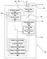
- FIG. 1illustrates a high level block diagram of a duplex camera 100 in accordance with aspects of the embodiments.
- the duplex camera 100contains optics as well as electronics.
- the size and complexity of, and heat generated by, the electronicscan dictate that some or most of the electronics be housed in a separate electronics enclosure.
- a light input 101passes through an imaging port 102 .
- the imaging port 102can be open, have a lens, a motorized zoom lens, an extension tube, or any of the other camera components commonly used in photography and video.
- the light input 101propagates through the imaging port 102 and parallel to an acceptance vector 105 .
- the acceptance vector 105is the direction light must travel in order to be imaged by the sensor arrays 107 , 108 .
- the light input 101has a visible light component that a wavelength selective mirror 103 directs along a first optical path 104 and an infrared component that the wavelength selective mirror 103 directs along a second optical path 106 .
- An infrared optics module 111images the infrared component onto an infrared sensor array 108 .
- a visible light optics module 109images the visible component onto a visible light sensor array 107 .
- the sensor arrays 107 , 108can be arrays of charge coupled devices, charge injection devices, photo diodes, CMOS transistors, or other light sensitive devices.
- the sensor arrays 107 , 108can be identical or they can be different types of sensors.
- the visible light sensor arraycan be a small format CMOS imager while the infrared sensor array can be a large format CMOS imager with a thermoelectric cooler.
- a reason for different sensor arrays 107 , 108is that the visible light sensor array receives many photons from the entire scene whereas the infrared optics module zooms in to image a person's iris onto the infrared imager, and therefore receives far fewer photons.
- Another reason for different sensor arrays 107 , 108is that the efficiencies of such arrays, and their ability to image properly under highly variable lighting conditions, are functions of both their construction and the wavelengths of light that they are imaging.
- a camera electronics module 118can contain an image acquisition module 117 , image processing module 116 , autofocus module 115 , and motion control module 114 .
- the image acquisition module 117obtains infrared and visible light images from the sensor arrays 107 , 108 and passes them to the image processing module 116 .
- the image processing module 116can locate faces and eyes and determine iris locations in the visible light image. The image processing module 116 can then use the iris location to produce an iris image from the infrared image.
- the autofocus module 115can run an autofocus algorithm and send instructions to a motion control module 114 that drives focusers 110 , 112 to focus the images.
- a driven focuser 110 , 112has at least one actuator or other means for changing focus.
- An actuatorcan be an electromagnetic device such as a motor, or a solenoid.
- An actuatorcan be electrostatic.
- Driven stages 119 , 120 , 121can change the areas imaged by the sensor arrays 107 , 108 .
- the consumer grade image stabilizers previously discussedare examples of driven stages 119 , 120 , 121 that do adjust the areas imaged by certain consumer grade cameras.
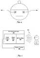
- FIG. 2illustrates a duplex camera 100 imaging a scene 201 illuminated by a collimated infrared light source 205 in accordance with aspects of the embodiments.
- the scene 201includes a face 203 with eyes 202 .
- the propagation vector 207is the direction that light propagates.
- the propagation vector 207is illustrated as directed into the imaging port 102 of the duplex camera 100 .
- the propagation vector 207is also sufficiently parallel to the acceptance vector 105 that the scene 201 can be imaged by the duplex camera 100 .
- the scene 201is an imaged scene.
- a motorized stage 204can point the duplex camera 100 directly at the face 203 with the result that light from the face 203 propagates into the imaging port 102 and parallel to the acceptance vector 105 .
- a collimated infrared light source 205can send a beam of infrared light of near-constant areal intensity directly toward the eye 202 and thereby illuminate the iris for the infrared sensor to image.
- the beamcan be steered by a driven stage 119 , 120 , 121 that steers the entire light source, by a driven stage the steers only the beam, or by a combination of stages.
- the motorized stage 204is a large driven stage that can pan, tilt, and zoom the entire duplex camera 100 .
- Driven stages 119 , 120 , 121 inside the duplex camera 100can achieve the same effect by changing the areas imaged by the sensor arrays 107 , 108 .
- driven stages 119 , 120 , 121can steer the entire duplex camera 100 , can steer the light input 101 when positioned ahead of the wavelength selective mirror 103 , can steer the infrared component when part of the infrared optics module 111 , and can steer the visible light component when part of the visible light optics module 109 .
- FIG. 3illustrates scene 201 elements in accordance with aspects of the embodiments.
- a scene image 301can be obtained by focusing a duplex camera 100 on a scene 201 and acquiring an image from the visible sensor array 107 .
- Image processing operationscan isolate a face image 302 inside the scene image 301 .
- Further image processingcan isolate eye images 303 , 304 in the face image 302 .
- Processing the eye images 303 , 304produce the iris locations 304 , 306 .
- the iris separation 307is the distance between the iris locations 305 , 306 .
- Those practiced in the arts of image processing and pattern recognitionknow of systems, techniques, and algorithms for locating faces in scenes 201 , eyes 202 in faces 203 , and irises in eyes 202 .
- FIG. 4illustrates iris images 401 , 402 in accordance with aspects of the embodiments.
- the duplex camera 100turns toward the face 203 in the scene 201 to acquire a scene image 301 .
- the scene image 301is processed to locate a face image 302 and one or more eye images 303 , 304 and iris locations 305 , 306 .
- FIG. 4illustrates iris images 401 and/or 402 obtained from the infrared sensor array.
- the infrared optics module 111 and the visible light optics module 109can be configured with different magnifications.
- the visible light optics module 109can have a magnification for imaging an entire scene 201 onto the visible light sensor array while the infrared optics module 111 have a magnification for imaging an iris within the scene 201 onto the infrared sensor array.
- the motorized stage 204can aim the duplex camera 100 to center the iris image 401 , 402 on the infrared sensor array.
- a driven stage 119 , 120 , 121can adjust the area imaged to position the iris image 401 , 402 on the infrared sensor while the duplex camera 100 is held still.
- the duplex camera 100can track the iris because the visible image and the infrared image can be obtained simultaneously.
- Those practiced in the arts of optical target tracking, autofocus, or image stabilizationare familiar with opto-mechanical assemblies for tracking, positioning, and centering images on a sensor array 107 , 108 .
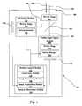
- FIG. 5illustrates a duplex camera 100 imaging a scene 201 illuminated by an infrared flash 505 in accordance with aspects of the embodiments.
- An infrared flash illuminator 501contains a flash control 502 , flash tube 503 , and infrared pass filter 504 .
- the duplex camera 100can trigger the infrared flash 505 after determining an iris location 305 , 306 and centering the iris image 401 , 402 on the infrared sensor array.
- the infrared flash illuminator 501illuminates the iris while the image acquisition module 117 acquires the iris image 401 , 402 .
- the flash control 502can activate the flash tube 503 upon receiving a trigger signal from the duplex camera 100 .
- the flash tube 503creates a flash of light.
- the infrared pass filter 504passes only the infrared light resulting in an infrared flash 505 .
- the infrared flash illuminator 501can generate either a radially expanding beam, of roughly constant square-angular intensity, independent of distance, or a collimated beam of roughly constant areal intensity, independent of distance. As with the collimated infrared light source 205 of FIG. 2 , a flash illuminator 501 or any other illuminator can be steered.
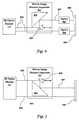
- FIG. 6illustrates a driven image distance separator 601 and two infrared sensor arrays 608 in accordance with aspects of the embodiments.
- the infrared component 606 of the light input 101 into a duplex camera 100can pass from the infrared optics module 111 and into a driven image distance separator 601 .
- a driven image distance separator 601is an optical component that moves one subimage closer to or farther from another subimage.
- a subimageis a portion of an image.
- a driven image distance separator 601can dynamically adjust the amount of subimage movement. Those practiced in optical systems are familiar with driven image distance separators 601 .
- a wavelength selective mirror 103can reflect the infrared component of a light input 101 along a second optical path 606 .
- the second optical path 606can enter a driven image distance separator 601 after passing through an infrared optics module 111 .
- the infrared component 606carries an infrared image.
- a first mirror 604can direct part of the infrared component 606 along a third optical path 607 that has a second mirror 605 and an infrared sensor array 608 . In this manner, two parts of an image can be separately imaged onto infrared sensor arrays 608 .
- Additional optics 602can be positioned along the optical paths 606 , 607 .
- the driven image distance separator 601 of FIG. 6is best suited for increasing the separation between subimages.
- Two infrared sensor arrays 608are used for the purpose of illustration. Note that a sensor array can also be positioned to replace the second mirror 605 and thereby reduce component count.
- FIG. 7illustrates a driven image distance separator 702 and a single infrared sensor array 108 in accordance with aspects of the embodiments.
- the positions of the first mirror 604 and second mirror 605are switched with respect to FIG. 6 .
- the illustrated driven image distance separator 701is best suited for decreasing the separation between subimages.
- a single sensor array 108can be used.
- FIGS. 3 , 4illustrated the determination of two iris locations 401 , 402 and an iris separation 307 .
- the driven image distance separators 601 , 701 of FIGS. 6 , 7can be used in the duplex camera 100 .
- the duplex camera's 100 second optical path 106can pass through the driven image distance separator 601 , 701 such that the right iris image 401 is imaged onto the sensor array 108 .
- the third optical path 607can be set to move the subimage containing the left iris image 402 onto the sensor array 108 . In this manner, both irises can be imaged simultaneously.
- FIG. 8illustrates a high level flow diagram of obtaining an iris image 401 , 402 in accordance with aspects of the embodiments.
- a duplex camera 100can obtain a light input 101 from an imaged scene 802 .
- a wavelength selective mirror 103separates the light input 101 into an infrared component 606 and a visible light component 803 .
- a visible light imageis produced 804 and an infrared image is also produced 805 .
- the iris location 305 , 306is determined 806 and used to isolate an iris image 401 , 402 within the infrared image 807 before the process is completed 808 .
- FIG. 8simply locates an iris image 401 , 402 within an infrared image.
- an infrared flash 505can be synchronized with producing the infrared image 805 .
- the duplex camera 100can be aimed to center the iris after the iris location 305 , 306 is determined 806 such that an infrared image with a centered iris can be obtained.
- driven stages 119 , 120 , 121alter the imaged area to center the iris after the iris location 305 , 306 is determined 806 such that an infrared image with a centered iris can be obtained.
- an infrared flash 505 or a steered collimated infrared light source 205can illuminate the iris.
- producing the IR image 805can include setting a driven image distance separator to 601 compensate for iris separation 307 such that two iris images 401 , 402 are obtained concurrently.
- FIG. 9illustrates a duplex camera 100 with a driven input optics module 901 in accordance with elements of certain embodiments.
- the driven input optics module 901contains a driven stage 902 that moves optical elements.
- a mirror 903can be one of the moved optical elements.
- the mirror 903can redirect a light input 904 to be parallel with the duplex camera's 100 acceptance vector 105 .
- the driven stage 902can move the mirror 903 to redirect the propagation vector 207 of the light input 904 .
Landscapes
- Engineering & Computer Science (AREA)
- General Physics & Mathematics (AREA)
- General Health & Medical Sciences (AREA)
- Human Computer Interaction (AREA)
- Physics & Mathematics (AREA)
- Health & Medical Sciences (AREA)
- Multimedia (AREA)
- Theoretical Computer Science (AREA)
- Ophthalmology & Optometry (AREA)
- Oral & Maxillofacial Surgery (AREA)
- Studio Devices (AREA)
- Image Input (AREA)
- Measurement Of The Respiration, Hearing Ability, Form, And Blood Characteristics Of Living Organisms (AREA)
Abstract
Description
Claims (17)
Priority Applications (2)
| Application Number | Priority Date | Filing Date | Title |
|---|---|---|---|
| US11/784,571US8111879B2 (en) | 2007-04-05 | 2007-04-05 | Face and iris imaging system and method |
| PCT/US2008/059116WO2008124427A1 (en) | 2007-04-05 | 2008-04-02 | Common face and iris imaging optics |
Applications Claiming Priority (1)
| Application Number | Priority Date | Filing Date | Title |
|---|---|---|---|
| US11/784,571US8111879B2 (en) | 2007-04-05 | 2007-04-05 | Face and iris imaging system and method |
Publications (2)
| Publication Number | Publication Date |
|---|---|
| US20080246917A1 US20080246917A1 (en) | 2008-10-09 |
| US8111879B2true US8111879B2 (en) | 2012-02-07 |
Family
ID=39469478
Family Applications (1)
| Application Number | Title | Priority Date | Filing Date |
|---|---|---|---|
| US11/784,571Active2030-04-13US8111879B2 (en) | 2007-04-05 | 2007-04-05 | Face and iris imaging system and method |
Country Status (2)
| Country | Link |
|---|---|
| US (1) | US8111879B2 (en) |
| WO (1) | WO2008124427A1 (en) |
Cited By (3)
| Publication number | Priority date | Publication date | Assignee | Title |
|---|---|---|---|---|
| US20140119617A1 (en)* | 2012-10-26 | 2014-05-01 | Oberthur Technologies | Biometric identification |
| US11003905B2 (en)* | 2014-09-25 | 2021-05-11 | Samsung Electronics Co., Ltd | Method and apparatus for iris recognition |
| US11205071B2 (en)* | 2018-07-16 | 2021-12-21 | Advanced New Technologies Co., Ltd. | Image acquisition method, apparatus, system, and electronic device |
Families Citing this family (28)
| Publication number | Priority date | Publication date | Assignee | Title |
|---|---|---|---|---|
| WO2008131201A1 (en) | 2007-04-19 | 2008-10-30 | Global Rainmakers, Inc. | Method and system for biometric recognition |
| KR20200090943A (en) | 2007-09-24 | 2020-07-29 | 애플 인크. | Embedded authentication systems in an electronic device |
| US8600120B2 (en) | 2008-01-03 | 2013-12-03 | Apple Inc. | Personal computing device control using face detection and recognition |
| KR20100057983A (en)* | 2008-11-24 | 2010-06-03 | 한국전자통신연구원 | Method for providing multi image scan in biometrics system |
| US20100186234A1 (en) | 2009-01-28 | 2010-07-29 | Yehuda Binder | Electric shaver with imaging capability |
| US8254768B2 (en)* | 2010-12-22 | 2012-08-28 | Michael Braithwaite | System and method for illuminating and imaging the iris of a person |
| US8638385B2 (en) | 2011-06-05 | 2014-01-28 | Apple Inc. | Device, method, and graphical user interface for accessing an application in a locked device |
| US9002322B2 (en) | 2011-09-29 | 2015-04-07 | Apple Inc. | Authentication with secondary approver |
| US8769624B2 (en) | 2011-09-29 | 2014-07-01 | Apple Inc. | Access control utilizing indirect authentication |
| CN111310619B (en) | 2012-05-18 | 2021-06-04 | 苹果公司 | Device, method and graphical user interface for manipulating a user interface |
| US9898642B2 (en) | 2013-09-09 | 2018-02-20 | Apple Inc. | Device, method, and graphical user interface for manipulating user interfaces based on fingerprint sensor inputs |
| DE102013015600A1 (en)* | 2013-09-19 | 2015-03-19 | Mühlbauer Ag | Apparatus, system and method for identifying a person |
| US10043185B2 (en) | 2014-05-29 | 2018-08-07 | Apple Inc. | User interface for payments |
| CN104252622A (en)* | 2014-10-15 | 2014-12-31 | 倪蔚民 | Mobile terminal front-mounting and iris identification integration photoelectric imaging system and method |
| JP2017045407A (en)* | 2015-08-28 | 2017-03-02 | キヤノン株式会社 | Information processor |
| DK179186B1 (en) | 2016-05-19 | 2018-01-15 | Apple Inc | REMOTE AUTHORIZATION TO CONTINUE WITH AN ACTION |
| DK179978B1 (en) | 2016-09-23 | 2019-11-27 | Apple Inc. | Image data for enhanced user interactions |
| CN108256406B (en)* | 2017-01-05 | 2023-11-03 | 广州市晶密电子有限公司 | Data processing method and device for realizing face recognition through eye positioning guidance |
| CN117077102A (en) | 2017-09-09 | 2023-11-17 | 苹果公司 | Implementation of biometric authentication |
| KR102185854B1 (en) | 2017-09-09 | 2020-12-02 | 애플 인크. | Implementation of biometric authentication |
| CN108539576B (en)* | 2018-05-30 | 2020-06-12 | Oppo广东移动通信有限公司 | Control system and mobile terminal for laser projector |
| US11170085B2 (en) | 2018-06-03 | 2021-11-09 | Apple Inc. | Implementation of biometric authentication |
| US11070718B2 (en)* | 2018-06-18 | 2021-07-20 | Flir Surveillance, Inc. | Image stabilization systems and methods |
| US10860096B2 (en) | 2018-09-28 | 2020-12-08 | Apple Inc. | Device control using gaze information |
| US11100349B2 (en) | 2018-09-28 | 2021-08-24 | Apple Inc. | Audio assisted enrollment |
| EP4264460A1 (en) | 2021-01-25 | 2023-10-25 | Apple Inc. | Implementation of biometric authentication |
| US12210603B2 (en) | 2021-03-04 | 2025-01-28 | Apple Inc. | User interface for enrolling a biometric feature |
| US12216754B2 (en) | 2021-05-10 | 2025-02-04 | Apple Inc. | User interfaces for authenticating to perform secure operations |
Citations (7)
| Publication number | Priority date | Publication date | Assignee | Title |
|---|---|---|---|---|
| US5956122A (en) | 1998-06-26 | 1999-09-21 | Litton Systems, Inc | Iris recognition apparatus and method |
| GB2375913A (en) | 2001-03-28 | 2002-11-27 | Hewlett Packard Co | Bispectral camera with target-locating ability |
| US20030012413A1 (en) | 2001-07-16 | 2003-01-16 | Matsushita Electric Industrial Co., Ltd. | Iris identification apparatus and iris image pickup apparatus |
| US6714665B1 (en)* | 1994-09-02 | 2004-03-30 | Sarnoff Corporation | Fully automated iris recognition system utilizing wide and narrow fields of view |
| WO2006023046A1 (en) | 2004-06-21 | 2006-03-02 | Nevengineering, Inc. | Single image based multi-biometric system and method |
| WO2006063076A2 (en) | 2004-12-07 | 2006-06-15 | Aoptix Technologies | Iris imaging using reflection from the eye |
| US7095901B2 (en) | 2001-03-15 | 2006-08-22 | Lg Electronics, Inc. | Apparatus and method for adjusting focus position in iris recognition system |
- 2007
- 2007-04-05USUS11/784,571patent/US8111879B2/enactiveActive
- 2008
- 2008-04-02WOPCT/US2008/059116patent/WO2008124427A1/enactiveApplication Filing
Patent Citations (7)
| Publication number | Priority date | Publication date | Assignee | Title |
|---|---|---|---|---|
| US6714665B1 (en)* | 1994-09-02 | 2004-03-30 | Sarnoff Corporation | Fully automated iris recognition system utilizing wide and narrow fields of view |
| US5956122A (en) | 1998-06-26 | 1999-09-21 | Litton Systems, Inc | Iris recognition apparatus and method |
| US7095901B2 (en) | 2001-03-15 | 2006-08-22 | Lg Electronics, Inc. | Apparatus and method for adjusting focus position in iris recognition system |
| GB2375913A (en) | 2001-03-28 | 2002-11-27 | Hewlett Packard Co | Bispectral camera with target-locating ability |
| US20030012413A1 (en) | 2001-07-16 | 2003-01-16 | Matsushita Electric Industrial Co., Ltd. | Iris identification apparatus and iris image pickup apparatus |
| WO2006023046A1 (en) | 2004-06-21 | 2006-03-02 | Nevengineering, Inc. | Single image based multi-biometric system and method |
| WO2006063076A2 (en) | 2004-12-07 | 2006-06-15 | Aoptix Technologies | Iris imaging using reflection from the eye |
Non-Patent Citations (3)
| Title |
|---|
| M.E. Bazakos, Y. Ma, A. H. Johnson; Fast Access Control Technology Solutions (FACTS); Proceedings. IEEE Conference on Advanced Video and Signal Based Surveillance, Italy, Sep. 15-Sep. 16, 2005. |
| PCT-Notification of Transmittal of the International Search Report and the Written Opinion of the International Searching Authority, or the Declaration, Date of Mailing Jun. 19, 2008. |
| Z. Zhang, R. Wang, K. Pan, S.Z. Li, P. Zhang; Fusion of Near Infrared Face and Iris Biometrics; Advances in Biometrics Lecture Notes in Computer Science, vol. 4642. |
Cited By (5)
| Publication number | Priority date | Publication date | Assignee | Title |
|---|---|---|---|---|
| US20140119617A1 (en)* | 2012-10-26 | 2014-05-01 | Oberthur Technologies | Biometric identification |
| US9224057B2 (en)* | 2012-10-26 | 2015-12-29 | Oberthur Technologies | Biometric identification |
| US11003905B2 (en)* | 2014-09-25 | 2021-05-11 | Samsung Electronics Co., Ltd | Method and apparatus for iris recognition |
| US11205071B2 (en)* | 2018-07-16 | 2021-12-21 | Advanced New Technologies Co., Ltd. | Image acquisition method, apparatus, system, and electronic device |
| US11244158B2 (en)* | 2018-07-16 | 2022-02-08 | Advanced New Technologies Co., Ltd. | Image acquisition method, apparatus, system, and electronic device |
Also Published As
| Publication number | Publication date |
|---|---|
| WO2008124427A1 (en) | 2008-10-16 |
| US20080246917A1 (en) | 2008-10-09 |
Similar Documents
| Publication | Publication Date | Title |
|---|---|---|
| US8111879B2 (en) | Face and iris imaging system and method | |
| AU2007220010B2 (en) | Single lens splitter camera | |
| US9277110B2 (en) | Tracking device and tracking method for prohibiting a tracking operation when a tracked subject is obstructed | |
| US7889435B2 (en) | Imaging device having a dual lens optical system | |
| KR100977499B1 (en) | Long Range Iris Image Acquisition System Using Panning and Tilting of Mirrors | |
| US8226234B2 (en) | Fundus camera | |
| JP2005004181A (en) | Visible / infrared lens system | |
| KR20100057983A (en) | Method for providing multi image scan in biometrics system | |
| JP2002341406A (en) | Authentication target imaging method and apparatus | |
| CN102572249A (en) | Dual-mode imaging optical system for face and iris | |
| JP2008046415A (en) | Lens device | |
| US7262805B2 (en) | Focus detecting system | |
| JP2001257928A (en) | Object tracking device | |
| EP1533999B1 (en) | Autofocus system | |
| US20030173518A1 (en) | Visible/infrared imaging camera | |
| US11115579B2 (en) | Method for switching optical fields of view | |
| US6809883B2 (en) | Autofocus system | |
| JP4622541B2 (en) | Iris photography device | |
| US8106992B2 (en) | Automatic focusing system using a magnification or reduction optical system | |
| JP4692425B2 (en) | Auto focus system | |
| JP2005128485A (en) | Visible light/infrared light photographing system | |
| JP2024115445A (en) | Optical device and imaging system | |
| JP4513056B2 (en) | Auto focus system | |
| JP3563895B2 (en) | Imaging device | |
| JPH06294856A (en) | Image guiding device for homing guiding |
Legal Events
| Date | Code | Title | Description |
|---|---|---|---|
| AS | Assignment | Owner name:HONEYWELL INTERNATIONAL INC., NEW JERSEY Free format text:ASSIGNMENT OF ASSIGNORS INTEREST;ASSIGNORS:PHINNEY, THOMAS L.;JELINEK, JAN;REEL/FRAME:019212/0766 Effective date:20070402 | |
| STCF | Information on status: patent grant | Free format text:PATENTED CASE | |
| FPAY | Fee payment | Year of fee payment:4 | |
| AS | Assignment | Owner name:GENTEX CORPORATION, MICHIGAN Free format text:ASSIGNMENT OF ASSIGNORS INTEREST;ASSIGNOR:HONEYWELL INTERNATIONAL INC.;REEL/FRAME:046384/0731 Effective date:20180226 | |
| AS | Assignment | Owner name:GENTEX CORPORATION, MICHIGAN Free format text:CORRECTIVE ASSIGNMENT TO CORRECT THE SUPPORTING LEGAL DOCUMENTATION PREVIOUSLY RECORDED ON REEL 046384 FRAME 0731. ASSIGNOR(S) HEREBY CONFIRMS THE ASSIGNMENT;ASSIGNOR:HONEYWELL INTERNATIONAL INC.;REEL/FRAME:046612/0025 Effective date:20180226 | |
| AS | Assignment | Owner name:GENTEX CORPORATION, MICHIGAN Free format text:CORRECTIVE ASSIGNMENT TO CORRECT THE SUPPORTING LEGAL DOCUMENTATION PREVIOUSLY RECORDED ON REEL 046384 FRAME 0731. ASSIGNOR(S) HEREBY CONFIRMS THE ASSIGNMENT;ASSIGNOR:HONEYWELL INTERNATIONAL INC.;REEL/FRAME:048779/0919 Effective date:20180226 | |
| FEPP | Fee payment procedure | Free format text:PETITION RELATED TO MAINTENANCE FEES GRANTED (ORIGINAL EVENT CODE: PTGR); ENTITY STATUS OF PATENT OWNER: LARGE ENTITY | |
| MAFP | Maintenance fee payment | Free format text:PAYMENT OF MAINTENANCE FEE, 8TH YEAR, LARGE ENTITY (ORIGINAL EVENT CODE: M1552); ENTITY STATUS OF PATENT OWNER: LARGE ENTITY Year of fee payment:8 | |
| MAFP | Maintenance fee payment | Free format text:PAYMENT OF MAINTENANCE FEE, 12TH YEAR, LARGE ENTITY (ORIGINAL EVENT CODE: M1553); ENTITY STATUS OF PATENT OWNER: LARGE ENTITY Year of fee payment:12 |