US8111791B2 - Differential evolution design of polyphase IIR decimation filters - Google Patents
Differential evolution design of polyphase IIR decimation filtersDownload PDFInfo
- Publication number
- US8111791B2 US8111791B2US11/614,001US61400106AUS8111791B2US 8111791 B2US8111791 B2US 8111791B2US 61400106 AUS61400106 AUS 61400106AUS 8111791 B2US8111791 B2US 8111791B2
- Authority
- US
- United States
- Prior art keywords
- coefficients
- current
- metric
- current set
- digital filter
- Prior art date
- Legal status (The legal status is an assumption and is not a legal conclusion. Google has not performed a legal analysis and makes no representation as to the accuracy of the status listed.)
- Expired - Fee Related, expires
Links
- 238000013461designMethods0.000titledescription7
- 238000000034methodMethods0.000claimsabstractdescription25
- 230000004044responseEffects0.000claimsabstractdescription11
- 230000006870functionEffects0.000description10
- 238000013139quantizationMethods0.000description6
- 238000012546transferMethods0.000description6
- 240000007124Brassica oleraceaSpecies0.000description2
- 235000003899Brassica oleracea var acephalaNutrition0.000description2
- 235000012905Brassica oleracea var viridisNutrition0.000description2
- 230000008901benefitEffects0.000description2
- 230000003111delayed effectEffects0.000description2
- 101100366940Mus musculus Stom geneProteins0.000description1
- 230000015556catabolic processEffects0.000description1
- 238000007796conventional methodMethods0.000description1
- 238000006731degradation reactionMethods0.000description1
- 238000011156evaluationMethods0.000description1
- 230000002068genetic effectEffects0.000description1
- 238000012986modificationMethods0.000description1
- 230000004048modificationEffects0.000description1
- 238000012545processingMethods0.000description1
- 238000005070samplingMethods0.000description1
Images


Classifications
- H—ELECTRICITY
- H03—ELECTRONIC CIRCUITRY
- H03H—IMPEDANCE NETWORKS, e.g. RESONANT CIRCUITS; RESONATORS
- H03H17/00—Networks using digital techniques
- H03H17/02—Frequency selective networks
- H03H17/04—Recursive filters
- H03H17/0416—Recursive filters with input-sampling frequency and output-delivery frequency which differ, e.g. extrapolation; Anti-aliasing
- H03H17/0427—Recursive filters with input-sampling frequency and output-delivery frequency which differ, e.g. extrapolation; Anti-aliasing characterized by the ratio between the input-sampling and output-delivery frequencies
- H03H17/0438—Recursive filters with input-sampling frequency and output-delivery frequency which differ, e.g. extrapolation; Anti-aliasing characterized by the ratio between the input-sampling and output-delivery frequencies the ratio being integer
- H03H17/045—Recursive filters with input-sampling frequency and output-delivery frequency which differ, e.g. extrapolation; Anti-aliasing characterized by the ratio between the input-sampling and output-delivery frequencies the ratio being integer where the output-delivery frequency is lower than the input sampling frequency, i.e. decimation
- H—ELECTRICITY
- H03—ELECTRONIC CIRCUITRY
- H03H—IMPEDANCE NETWORKS, e.g. RESONANT CIRCUITS; RESONATORS
- H03H17/00—Networks using digital techniques
- H03H17/02—Frequency selective networks
- H03H17/0248—Filters characterised by a particular frequency response or filtering method
- H03H17/0264—Filter sets with mutual related characteristics
- H03H17/0273—Polyphase filters
- H03H17/0277—Polyphase filters comprising recursive filters
Definitions
- Provisional Patent Applicationentitled “Differential Evolution Design of Polyphase IIR Decimation Filters,” Ser. No. 60/752,619, filed on Dec. 20, 2005.
- Provisional Applicationis hereby incorporated by reference in its entirety.
- the present inventionrelates to the design of an M-path, polyphase IIR decimate-by-M filter.
- Digital M-path, polyphase infinite impulse response (IIR) filtersmay be used as decimators (interpolators) with a decimation (interpolation) ratio M, for M greater than one.
- Such filtersare based on the M-tap finite impulse response (FIR) filter, in which the coefficients are replaced by allpass filters.
- FIRfinite impulse response
- Polyphase IIR filtersprovide high stop band attenuation and low pass band ripple, even with a relatively small number of coefficients.
- FIG. 1shows an example of an M-path, polyphase IIR decimate-by-M filter structure 100 .
- filter 100receives input samples x(n), which are provided to an M- 1 stage tapped delay line.
- Input sample x(n) and the output samples of the M- 1 delay line tapsare down-sampled by a factor of M (steps 101 - 0 to 101 -( m - 1 )).
- Each of the M down-sampled valuesare provided as input to a corresponding one of M allpass filters 102 - 0 to 102 -( m - 1 ).
- the filtered output valuesare summed at summer 103 ; thereafter, the sum is scaled by 1/M to form the output sample y(m).
- the transfer function of M-path, polyphase IIR decimator 100is given by:
- the total number of filter coefficientsis M ⁇ N.
- a method for designing a digital filterincludes: (a) selecting a predetermined number of current sets of coefficients for the digital filter; (b) selecting a metric for evaluating coefficients of the digital filter; (c) computing a metric for each current set of coefficients; (d) deriving a next set of coefficients based on a subset of the current set of coefficients; (e) computing the metric for the next set of coefficients; (f) replacing a selected one of the current set of coefficients based on comparing the metric for the next set of coefficients with the metric for the selected current set of coefficients; and (g) iterating steps (a) to (e) until a termination criterion is met.
- the selected metricrepresents a desired stop band response.
- the next set of coefficientsmay be derived by adjusting a first current set of coefficients by a weighted difference between a second current set of coefficients and a third current set of coefficients.
- the weighted differencemay be obtained by multiplying a predetermined factor to the difference between the second current set of coefficients and the third current set of coefficients.
- a scalingis performed such that the next set of coefficients does not include a pole outside of the unit circle.
- FIG. 1shows an example of a conventional M-path, polyphase IIR decimate-by-M filter structure 100 .
- FIG. 2shows an example of 2-path, decimate-by-2 structure 200 , in accordance with one embodiment of the present invention.
- FIG. 3shows an example of 3-path, decimate-by-3-structure 300 , in accordance with one embodiment of the present invention.
- FIG. 4shows structure 400 of a single real section (single coefficient) of an allpass filter.
- FIG. 5shows cascading three real sections 501 , 502 and 503 to form a 3-coefficient filter, in which delay elements are shared between stages.
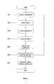
- FIG. 6shows one embodiment of a method for designing a digital filter.
- FIG. 2shows an example of 2-path, decimate-by-2 structure 200
- FIG. 3shows an example of a specific 3-path, decimate-by-3-structure 300
- FIG. 4shows structure 400 of a single real section (i.e., single-coefficient) of an allpass filter.
- input value x(n)is subtracted the output value of scale-by-beta amplifier 401 , delayed by one unit. The difference is provided to scale-by-beta amplifier 401 .
- the output value of scale-by-beta amplifier 401is added to the input value x(n), delayed by one unit to form the filter output.
- structure 400has the transfer function:
- FIG. 5shows cascading three real sections 501 , 502 and 503 to form a 3-coefficient filter, in which delay elements are shared between stages.
- Lutovac and Milic 1 and Krukowski and Kale 2are textbooks that provide detailed descriptions of the theory and design of N-path polyphase IIR filters, including algorithms for computing the required allpass filter coefficients.
- the computed coefficientsare necessarily quantized to a finite number of bits in an actual implementation. Quantization by rounding or truncation may result in significant filter performance degradation (e.g., larger pass band ripple and smaller stop band attenuation). To find the best performance, given a C coefficients and B bits resolution in the quantized values, it may be necessary to evaluate all 2*B*C possible filters.
- a pole outside of the unit circlemay cause a filter to be unstable.
- To discard candidate coefficient sets that have poles outside the unit circleslows down the convergence of the DE algorithm.
- these candidate coefficient setsare scaled by 1/ ⁇ times the maximum magnitude of the coefficients in that set, where ⁇ is a number greater than 1.0.
- the present inventionalso takes advantage of the structure of the M-path polyphase decimator, which ensures that minimizing the maximum stop band magnitude response also minimizes the pass band ripple.
- the metricis defined as the maximum stop band magnitude response.
- the “NthPathNthBand_DE” functionoutput (a) “beta”, which are filter coefficients arranged in an “nPaths” by “nc” array, with i th each row corresponding to i th path; (b) “mpr”, the maximum pass band ripple (in dB); “msa”, the minimum stop band attenuation (in dB) and “pgdv”, the pass band group delay variation (in samples).
- Appendix Bprovides an example of an output filter design.
- the DE algorithmrandomly selects “NP” sets of B-bit coefficients, P old .
- a metricis selected, which may be, for example, the maximum stop band magnitude response. This metric is computed for each of the “NP” coefficient sets. The number identifying the set with the smallest metric is stored in “bestk” and the smallest metric value is stored in “best”.
- the DE algorithmproceeds for “Passes” iterations. During each iteration, new sets P new of coefficients are initialized to the values of the old set P old .
- a candidate replacement setis obtained by randomly selecting a three of the existing coefficient sets (say, set numbers “rp( 1 )”, “rp( 2 )”, and “rp( 3 )” respectively) and computing the values of set rp( 1 ) minus 0.85 times the values of the differences between set rp( 2 ) and set rp( 3 ), rounded to a “B” bit quantization. If the maximum magnitude of the coefficients in the candidate set exceeds 1.0, then the candidate set is scaled by dividing by 1.1 times that maximum magnitude, and rounded to “B” bit quantization.
- the candidate coefficient setreplaces an existing coefficient set, if the metric of the candidate set (e.g., the maximum stop band magnitude response) is less than the metric of the existing set.
- “beta”is set equal to the surviving coefficient set with the best metric. While the value 0.85 is selected for providing good performance, any positive number less than 1.0 may be used. Similarly, while the value 1.1 provides good performance, any value greater than 1.0 may also be used.
- the MATLAB output in Appendix Bis for a 3-path, decimate-by-3 decimator with 4 sections (coefficients) per path (i.e., a total of 12 coefficients).
- the input parameterswere 8-bit coefficient quantization, pass band of 0 to 0.1F s , stopband of 0.2F s to 0.333Fs, 100 coefficient-point sets, and 1,000 iterations.
- the programrequired 35 seconds to run on a 3.6 GHz workstation.
- the transfer functions for the 12 real sections, 4 per path,are shown in both decimal fraction and hexadecimal fraction notations.
- the quantized coefficient decimatorhas maximum pass band ripple of less than 10 ⁇ 4 dB, minimum stop band attenuation of ⁇ 48 dB, and maximum pass band group delay variation of 4.5 samples.
- FIG. 6depicts one embodiment of the present disclosure.
- Box 601discloses selecting a predetermined number of current sets of coefficients.
- Box 602discloses selecting a metric for evaluating coefficients of the digital filter.
- Box 603discloses scaling the selected current sets of coefficients by a function of the current sets of coefficients.
- Box 604discloses deriving a next set of coefficients based on a subset of the scaled current set of coefficients.
- Box 605discloses computing the metric for the next set of coefficients. Boxes 601 , 602 , 603 , 604 and 605 are iterated until a termination criterion is met.
- Box 606discloses comparing the computed metrics and replacing the current set of coefficients with the next set of coefficients if a condition is satisfied. For instance, the current set of coefficients are replaced with the next set of coefficients if the computed metric for the respective next set of coefficients is less than the computed metric for the respective current set of coefficients.
Landscapes
- Physics & Mathematics (AREA)
- Engineering & Computer Science (AREA)
- Computer Hardware Design (AREA)
- Mathematical Physics (AREA)
- Compression, Expansion, Code Conversion, And Decoders (AREA)
- Complex Calculations (AREA)
Abstract
Description
Assuming that each of the M allpass filters102-0 to102-(M-1) has N real sections (i.e. N coefficients), the transfer functions of the allpass filters102-0 to102-(M-1) have the form:
Substituting the allpass filter transfer functions into the transfer function of M-path,
Thus, the total number of filter coefficients is M×N.
Claims (25)
Priority Applications (1)
| Application Number | Priority Date | Filing Date | Title |
|---|---|---|---|
| US11/614,001US8111791B2 (en) | 2005-12-20 | 2006-12-20 | Differential evolution design of polyphase IIR decimation filters |
Applications Claiming Priority (2)
| Application Number | Priority Date | Filing Date | Title |
|---|---|---|---|
| US75261905P | 2005-12-20 | 2005-12-20 | |
| US11/614,001US8111791B2 (en) | 2005-12-20 | 2006-12-20 | Differential evolution design of polyphase IIR decimation filters |
Publications (2)
| Publication Number | Publication Date |
|---|---|
| US20070153946A1 US20070153946A1 (en) | 2007-07-05 |
| US8111791B2true US8111791B2 (en) | 2012-02-07 |
Family
ID=38224410
Family Applications (1)
| Application Number | Title | Priority Date | Filing Date |
|---|---|---|---|
| US11/614,001Expired - Fee RelatedUS8111791B2 (en) | 2005-12-20 | 2006-12-20 | Differential evolution design of polyphase IIR decimation filters |
Country Status (1)
| Country | Link |
|---|---|
| US (1) | US8111791B2 (en) |
Families Citing this family (1)
| Publication number | Priority date | Publication date | Assignee | Title |
|---|---|---|---|---|
| DE102018129062B3 (en) | 2018-11-19 | 2020-04-23 | Infineon Technologies Ag | FILTERING METHOD AND FILTER |
Citations (18)
| Publication number | Priority date | Publication date | Assignee | Title |
|---|---|---|---|---|
| US5852681A (en)* | 1995-04-20 | 1998-12-22 | Massachusetts Institute Of Technology | Method and apparatus for eliminating artifacts in data processing and compression systems |
| US5877971A (en)* | 1994-09-20 | 1999-03-02 | Sony Corporation | Digital signal processing |
| US6237016B1 (en)* | 1995-09-05 | 2001-05-22 | Intel Corporation | Method and apparatus for multiplying and accumulating data samples and complex coefficients |
| US6411892B1 (en) | 2000-07-13 | 2002-06-25 | Global Locate, Inc. | Method and apparatus for locating mobile receivers using a wide area reference network for propagating ephemeris |
| US6417801B1 (en) | 2000-11-17 | 2002-07-09 | Global Locate, Inc. | Method and apparatus for time-free processing of GPS signals |
| US6429814B1 (en) | 2000-11-17 | 2002-08-06 | Global Locate, Inc. | Method and apparatus for enhancing a global positioning system with terrain model |
| US6453237B1 (en) | 1999-04-23 | 2002-09-17 | Global Locate, Inc. | Method and apparatus for locating and providing services to mobile devices |
| US6542820B2 (en) | 2001-06-06 | 2003-04-01 | Global Locate, Inc. | Method and apparatus for generating and distributing satellite tracking information |
| US20030074381A1 (en)* | 2001-08-08 | 2003-04-17 | Awad Thomas Jefferson | Method and apparatus for generating a set of filter coefficients |
| US6560534B2 (en) | 2001-06-06 | 2003-05-06 | Global Locate, Inc. | Method and apparatus for distributing satellite tracking information |
| US6606346B2 (en) | 2001-05-18 | 2003-08-12 | Global Locate, Inc. | Method and apparatus for computing signal correlation |
| US20040071206A1 (en)* | 2002-08-13 | 2004-04-15 | Fujitsu Limited. | Digital filter adaptively learning filter coefficient |
| US20040146205A1 (en)* | 2002-09-30 | 2004-07-29 | Canon Kabushiki Kaisha | Digital video compression |
| US20040190660A1 (en)* | 2003-03-31 | 2004-09-30 | Morris Bradley John | Digital receiver and method |
| US20060056640A1 (en)* | 2004-08-17 | 2006-03-16 | Matthew Barnhill | Configurable recursive digital filter for processing television audio signals |
| US20060083296A1 (en)* | 2004-10-20 | 2006-04-20 | Jishnu Bhattacharjee | Method and apparatus for generating coefficients in continuous time equalizers |
| US20060181644A1 (en)* | 2003-04-10 | 2006-08-17 | Gerard De Haan | Spatial image conversion |
| US20080256160A1 (en)* | 2005-10-31 | 2008-10-16 | Dan Lusk | Reduction of Digital Filter Delay |
- 2006
- 2006-12-20USUS11/614,001patent/US8111791B2/ennot_activeExpired - Fee Related
Patent Citations (22)
| Publication number | Priority date | Publication date | Assignee | Title |
|---|---|---|---|---|
| US5877971A (en)* | 1994-09-20 | 1999-03-02 | Sony Corporation | Digital signal processing |
| US5852681A (en)* | 1995-04-20 | 1998-12-22 | Massachusetts Institute Of Technology | Method and apparatus for eliminating artifacts in data processing and compression systems |
| US6237016B1 (en)* | 1995-09-05 | 2001-05-22 | Intel Corporation | Method and apparatus for multiplying and accumulating data samples and complex coefficients |
| US6453237B1 (en) | 1999-04-23 | 2002-09-17 | Global Locate, Inc. | Method and apparatus for locating and providing services to mobile devices |
| US6484097B2 (en) | 1999-04-23 | 2002-11-19 | Global Locate, Inc. | Wide area inverse differential GPS |
| US6487499B1 (en) | 1999-04-23 | 2002-11-26 | Global Locate, Inc. | Method for adjusting a pseudo-range model |
| US6510387B2 (en) | 1999-04-23 | 2003-01-21 | Global Locate, Inc. | Correction of a pseudo-range model from a GPS almanac |
| US6411892B1 (en) | 2000-07-13 | 2002-06-25 | Global Locate, Inc. | Method and apparatus for locating mobile receivers using a wide area reference network for propagating ephemeris |
| US6704651B2 (en) | 2000-07-13 | 2004-03-09 | Global Locate, Inc. | Method and apparatus for locating mobile receivers using a wide area reference network for propagating ephemeris |
| US6417801B1 (en) | 2000-11-17 | 2002-07-09 | Global Locate, Inc. | Method and apparatus for time-free processing of GPS signals |
| US6429814B1 (en) | 2000-11-17 | 2002-08-06 | Global Locate, Inc. | Method and apparatus for enhancing a global positioning system with terrain model |
| US6606346B2 (en) | 2001-05-18 | 2003-08-12 | Global Locate, Inc. | Method and apparatus for computing signal correlation |
| US6542820B2 (en) | 2001-06-06 | 2003-04-01 | Global Locate, Inc. | Method and apparatus for generating and distributing satellite tracking information |
| US6560534B2 (en) | 2001-06-06 | 2003-05-06 | Global Locate, Inc. | Method and apparatus for distributing satellite tracking information |
| US20030074381A1 (en)* | 2001-08-08 | 2003-04-17 | Awad Thomas Jefferson | Method and apparatus for generating a set of filter coefficients |
| US20040071206A1 (en)* | 2002-08-13 | 2004-04-15 | Fujitsu Limited. | Digital filter adaptively learning filter coefficient |
| US20040146205A1 (en)* | 2002-09-30 | 2004-07-29 | Canon Kabushiki Kaisha | Digital video compression |
| US20040190660A1 (en)* | 2003-03-31 | 2004-09-30 | Morris Bradley John | Digital receiver and method |
| US20060181644A1 (en)* | 2003-04-10 | 2006-08-17 | Gerard De Haan | Spatial image conversion |
| US20060056640A1 (en)* | 2004-08-17 | 2006-03-16 | Matthew Barnhill | Configurable recursive digital filter for processing television audio signals |
| US20060083296A1 (en)* | 2004-10-20 | 2006-04-20 | Jishnu Bhattacharjee | Method and apparatus for generating coefficients in continuous time equalizers |
| US20080256160A1 (en)* | 2005-10-31 | 2008-10-16 | Dan Lusk | Reduction of Digital Filter Delay |
Also Published As
| Publication number | Publication date |
|---|---|
| US20070153946A1 (en) | 2007-07-05 |
Similar Documents
| Publication | Publication Date | Title |
|---|---|---|
| Hogenauer | An economical class of digital filters for decimation and interpolation | |
| JPH11261376A (en) | Digital iir filter by few multipliers | |
| Pun et al. | On the design and efficient implementation of the Farrow structure | |
| Yli-Kaakinen et al. | A systematic algorithm for the design of lattice wave digital filters with short-coefficient wordlength | |
| Eddla et al. | Low area and power-efficient FPGA implementation of improved AM-CSA-IIR filter design for the DSP application | |
| US20030195910A1 (en) | Method of designing polynomials for controlling the slewing of adaptive digital filters | |
| US7196648B1 (en) | Non-integer decimation using cascaded intergrator-comb filter | |
| US7117235B2 (en) | Digital decimation filter having finite impulse response (FIR) decimation stages | |
| US8111791B2 (en) | Differential evolution design of polyphase IIR decimation filters | |
| Sullivan et al. | PCLS IIR digital filters with simultaneous frequency response magnitude and group delay specifications | |
| EP0559154B1 (en) | Digital filter | |
| Krukowski et al. | DSP system design: Complexity reduced IIR filter implementation for practical applications | |
| US7774394B2 (en) | Exponentiated polyphase digital filter | |
| Bellanger | Computation rate and storage estimation in multirate digital filtering with half-band filters | |
| US7027502B2 (en) | Run-time coefficient generation for digital filter with slewing bandwidth | |
| US20070220073A1 (en) | Digital filter and method for designing digital filters | |
| Hogenauer | A class of digital filters for decimation and interpolation | |
| Lee et al. | A weighted least-square-based approach to FIR filter design using the frequency-response masking technique | |
| Anzova et al. | An algorithm for the design of multiplierless IIR filters as a parallel connection of two all-pass filters | |
| JPH10509011A (en) | Improved digital filter | |
| Kotha et al. | A study on strategies and Mutant factor in differential evolution algorithm for FIR filter design | |
| Johnson | Optimal linear phase digital filter design by one-phase linear programming | |
| Saramäki | Computationally efficient narrowband linear-phase FIR filters | |
| JP4535548B2 (en) | Apparatus and method for anchoring a predetermined point of impulse frequency response of a physical realization filter | |
| Deshpande et al. | Highly narrow rejection bandwidth finite impulse response notch filters for communication |
Legal Events
| Date | Code | Title | Description |
|---|---|---|---|
| AS | Assignment | Owner name:SIRF TECHNOLOGY, INC., CALIFORNIA Free format text:ASSIGNMENT OF ASSIGNORS INTEREST;ASSIGNOR:STURZA, MARK ALAN;REEL/FRAME:019031/0805 Effective date:20070308 | |
| AS | Assignment | Owner name:CSR TECHNOLOGY INC., CALIFORNIA Free format text:CHANGE OF NAME;ASSIGNOR:SIRF TECHNOLOGY, INC.;REEL/FRAME:027437/0324 Effective date:20101119 | |
| STCF | Information on status: patent grant | Free format text:PATENTED CASE | |
| FPAY | Fee payment | Year of fee payment:4 | |
| FEPP | Fee payment procedure | Free format text:PAYOR NUMBER ASSIGNED (ORIGINAL EVENT CODE: ASPN); ENTITY STATUS OF PATENT OWNER: LARGE ENTITY | |
| FEPP | Fee payment procedure | Free format text:MAINTENANCE FEE REMINDER MAILED (ORIGINAL EVENT CODE: REM.); ENTITY STATUS OF PATENT OWNER: LARGE ENTITY | |
| LAPS | Lapse for failure to pay maintenance fees | Free format text:PATENT EXPIRED FOR FAILURE TO PAY MAINTENANCE FEES (ORIGINAL EVENT CODE: EXP.); ENTITY STATUS OF PATENT OWNER: LARGE ENTITY | |
| STCH | Information on status: patent discontinuation | Free format text:PATENT EXPIRED DUE TO NONPAYMENT OF MAINTENANCE FEES UNDER 37 CFR 1.362 | |
| FP | Lapsed due to failure to pay maintenance fee | Effective date:20200207 | |
| AS | Assignment | Owner name:QUALCOMM INCORPORATED, CALIFORNIA Free format text:ASSIGNMENT OF ASSIGNORS INTEREST;ASSIGNOR:CSR TECHNOLOGY INC.;REEL/FRAME:069221/0001 Effective date:20241004 |