US8111698B2 - Method of performing a layer operation in a communications network - Google Patents
Method of performing a layer operation in a communications networkDownload PDFInfo
- Publication number
- US8111698B2 US8111698B2US11/094,436US9443605AUS8111698B2US 8111698 B2US8111698 B2US 8111698B2US 9443605 AUS9443605 AUS 9443605AUS 8111698 B2US8111698 B2US 8111698B2
- Authority
- US
- United States
- Prior art keywords
- upper layer
- data packet
- layer
- time stamp
- lower layer
- Prior art date
- Legal status (The legal status is an assumption and is not a legal conclusion. Google has not performed a legal analysis and makes no representation as to the accuracy of the status listed.)
- Expired - Fee Related, expires
Links
- 238000004891communicationMethods0.000titleclaimsdescription43
- 238000000034methodMethods0.000titleclaimsdescription21
- 230000005540biological transmissionEffects0.000claimsdescription18
- 230000008569processEffects0.000claimsdescription8
- 230000003247decreasing effectEffects0.000claims2
- 230000009471actionEffects0.000abstractdescription9
- 238000010586diagramMethods0.000description11
- 230000006835compressionEffects0.000description8
- 238000007906compressionMethods0.000description8
- 230000010267cellular communicationEffects0.000description5
- 230000004044responseEffects0.000description4
- 230000007246mechanismEffects0.000description3
- 230000001413cellular effectEffects0.000description2
- 239000000463materialSubstances0.000description2
- 238000012986modificationMethods0.000description2
- 230000004048modificationEffects0.000description2
- 238000012546transferMethods0.000description2
- 238000012937correctionMethods0.000description1
- 238000001514detection methodMethods0.000description1
- 230000009365direct transmissionEffects0.000description1
- 230000008030eliminationEffects0.000description1
- 238000003379elimination reactionMethods0.000description1
- 238000005538encapsulationMethods0.000description1
- 238000013467fragmentationMethods0.000description1
- 238000006062fragmentation reactionMethods0.000description1
- 238000010295mobile communicationMethods0.000description1
- 238000012545processingMethods0.000description1
- 230000011218segmentationEffects0.000description1
- 230000001960triggered effectEffects0.000description1
Images


Classifications
- H—ELECTRICITY
- H04—ELECTRIC COMMUNICATION TECHNIQUE
- H04L—TRANSMISSION OF DIGITAL INFORMATION, e.g. TELEGRAPHIC COMMUNICATION
- H04L1/00—Arrangements for detecting or preventing errors in the information received
- H04L1/12—Arrangements for detecting or preventing errors in the information received by using return channel
- H04L1/16—Arrangements for detecting or preventing errors in the information received by using return channel in which the return channel carries supervisory signals, e.g. repetition request signals
- H04L1/18—Automatic repetition systems, e.g. Van Duuren systems
- H04L1/1829—Arrangements specially adapted for the receiver end
- H04L1/1854—Scheduling and prioritising arrangements
- H—ELECTRICITY
- H04—ELECTRIC COMMUNICATION TECHNIQUE
- H04L—TRANSMISSION OF DIGITAL INFORMATION, e.g. TELEGRAPHIC COMMUNICATION
- H04L67/00—Network arrangements or protocols for supporting network services or applications
- H04L67/50—Network services
- H04L67/60—Scheduling or organising the servicing of application requests, e.g. requests for application data transmissions using the analysis and optimisation of the required network resources
- H—ELECTRICITY
- H04—ELECTRIC COMMUNICATION TECHNIQUE
- H04L—TRANSMISSION OF DIGITAL INFORMATION, e.g. TELEGRAPHIC COMMUNICATION
- H04L9/00—Cryptographic mechanisms or cryptographic arrangements for secret or secure communications; Network security protocols
- H04L9/40—Network security protocols
- H—ELECTRICITY
- H04—ELECTRIC COMMUNICATION TECHNIQUE
- H04L—TRANSMISSION OF DIGITAL INFORMATION, e.g. TELEGRAPHIC COMMUNICATION
- H04L1/00—Arrangements for detecting or preventing errors in the information received
- H04L1/12—Arrangements for detecting or preventing errors in the information received by using return channel
- H04L1/16—Arrangements for detecting or preventing errors in the information received by using return channel in which the return channel carries supervisory signals, e.g. repetition request signals
- H04L1/18—Automatic repetition systems, e.g. Van Duuren systems
- H04L1/1812—Hybrid protocols; Hybrid automatic repeat request [HARQ]
- Y—GENERAL TAGGING OF NEW TECHNOLOGICAL DEVELOPMENTS; GENERAL TAGGING OF CROSS-SECTIONAL TECHNOLOGIES SPANNING OVER SEVERAL SECTIONS OF THE IPC; TECHNICAL SUBJECTS COVERED BY FORMER USPC CROSS-REFERENCE ART COLLECTIONS [XRACs] AND DIGESTS
- Y10—TECHNICAL SUBJECTS COVERED BY FORMER USPC
- Y10S—TECHNICAL SUBJECTS COVERED BY FORMER USPC CROSS-REFERENCE ART COLLECTIONS [XRACs] AND DIGESTS
- Y10S370/00—Multiplex communications
- Y10S370/901—Wide area network
- Y10S370/902—Packet switching
- Y10S370/903—Osi compliant network
Definitions
- the present inventionrelates generally to a method of performing a layer operation in a communications network.
- a cellular communications networktypically includes a variety of communication nodes coupled by wireless or wired connections and accessed through different types of communications channels.
- Each of the communication nodesincludes a protocol stack that processes the data transmitted and received over the communications channels.
- the operation and configuration of the various communication nodescan differ and are often referred to by different names.
- Such communications systemsinclude, for example, a Code Division Multiple Access 2000 (CDMA2000) system and Universal Mobile Telecommunications System (UMTS).
- UMTSis a wireless telephony standard which describes a set of protocol standards. For example, UMTS sets forth the protocol standards for the transmission of voice and data between a base station (BS) and a mobile or user equipment (UE).
- the UMTSis divided into a plurality of layers.
- Layer-1 protocolshandle digital radio transmission (e.g., encoding data packets for transmission, decoding received data packets, forward error correction, etc.).
- Layer-2 protocolse.g., radio link control (RLC)
- RLCradio link control
- Layer-3 protocolsinclude end-to-end protocols (e.g., IP, TCP, UDP, RTP, etc.).
- the layer numbersdenote a layer hierarchy where lower layer numbers indicate lower layers relative to higher layer numbers, and vice versa.
- the layersdo not necessarily communicate with each other. In other words, information determined at a given layer or extracted from operations at a given layer is typically unavailable at other layers. Also, with regard to the transmission of data packets, layers do not examine data packet contents received from upper layers, instead performing layer specific operations (e.g., encapsulation) and passing the data packets to a lower layer.
- layer specific operationse.g., encapsulation
- a lower layerreceives upper layer information from an upper layer.
- the lower layerperforms a scheduling operation based on the received upper layer information. For example, if the upper layer information is a time stamp associated with a delivery deadline for an upper layer data packet, the lower layer discards the upper layer data packet if the time stamp associated with the upper layer data packet is expired.
- a lower layerreceives at least one upper layer data packet from the upper layer.
- the lower layeranalyzes the at least one upper layer data packet and determines a scheduling operation. For example, the lower layer may modify the at least one upper layer data packet if the at least one upper layer data packet is an acknowledgment and an additional data packet to be acknowledged is received at the lower layer after the acknowledgment is generated. The modification may be to include a further acknowledgment for the additional data packet in the upper layer data packet.
- an upper layerreceives lower layer information from a lower layer.
- the upper layerperforms an action based on the received lower layer information. For example, the upper layer disables header compression on at least one data packet if the lower layer information indicates a lost data packet.
- FIG. 1illustrates a block diagram of a cellular communications system for mobile devices including an integrated base station according to an example embodiment of the present invention.
- FIG. 2is a block diagram illustrating an integrated base station according to another example embodiment of the present invention.
- FIG. 3illustrates a communication flow diagram for performing a lower layer operation according to another example embodiment of the present invention.
- FIG. 4illustrates another communication flow diagram for performing a lower layer operation according to an example embodiment of the present invention.
- FIG. 5illustrates a communication flow diagram for performing an upper layer operation according to another example embodiment of the present invention.
- FIG. 1illustrates a block diagram of a cellular communications system 100 for mobile devices including an integrated base station 130 according to an example embodiment of the present invention.
- the communications system 100also includes a core network 110 and a mobile device 120 .
- the communications system 100may be a conventional communications system such as a Universal Mobile Telecommunications System (UMTS) having multiple communications nodes coupled through wireless or wired mediums.
- UMTSUniversal Mobile Telecommunications System
- GSMGlobal System for Mobile Communications
- the discussion regarding a UMTSalso applies to other cellular communications systems and components.
- the integrated base station 130is representative of the other integrated base stations that are illustrated.
- the communications system 100may include additional components or systems that are not illustrated or discussed, but are typically employed in a conventional communications system.
- the core network 110may be a conventional core network configured to handle voice and (IP) back-haul.
- the core network 110includes communication nodes or switches coupled via connection lines. As illustrated, the core network 10 connects the integrated base station 130 to other integrated base stations and conventional RNCs and Node Bs. Additionally, the core network 110 can provide gateways to other networks (ISDN, Internet, etc.).
- the mobile device 120may be a conventional cellular telephone configured to operate in the communications system 100 .
- the mobile device 120may be a UMTS enabled cellular telephone.
- the mobile device 120may also be another wireless device that is configured to operate in the communications system 100 , such as, a personal digital assistant (PDA), a computer, an MP3 player, etc.
- PDApersonal digital assistant
- the integrated base station 130is coupled to the core network 110 via a wired connection and to the mobile device 120 via a wireless connection.
- the integrated base station 130is configured to include the functionality of a conventional RNC and a conventional Node B in a single processing entity.
- the integrated base station 130includes a first data interface 132 , a second data interface 133 and a communications processor 134 having a protocol stack 138 , a buffer 136 and a Radio Resource Control (RRC) layer 137 .
- RRCRadio Resource Control
- the integrated base station 130includes additional components or features that are not material to the present invention but are typically employed in a conventional RNC or Node B to transmit data units between a core network and a mobile device.
- the communications processor 134is configured to process data units from the first data interface 132 and the second data interface 133 .
- the buffer 136is configured to queue data units from the core network 110 for the protocol stack 138 . In FIG. 1 , the buffer 136 is located on top of the protocol stack 138 .
- the protocol stack 138is configured to produce data units suitable for direct transmission to the mobile device 120 .
- the protocol stack 138provides a single location that receives data units from the core network 110 and transmits the data units with the proper protocols to the mobile device 120 .
- the protocol stack 138includes a Packet Data Convergence Protocol (PDCP) layer, a Radio Link Control (RLC) layer, a Media Access Control (MAC) layer, and a High Speed Downlink Packet Access (HPSPA) layer.
- PDCPPacket Data Convergence Protocol
- RLCRadio Link Control
- MACMedia Access Control
- HPSPAHigh Speed Downlink Packet Access
- the protocol stack 138may include other or additional protocol layers in other embodiments.
- the HPSPA layermay not be included in the protocol stack 138 .
- the protocol stack 138may be extended to include such layer-2 protocol functionality as point-to-point protocol (PPP) layer and radio link protocol (RLP) layer instead of the PDCP layer and the RLC layer that is associated with a UMTS.
- PPPpoint-to-point protocol
- RLPradio link protocol
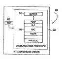
- FIG. 2is a block diagram illustrating an integrated base station 200 according to another example embodiment of the present invention.
- the integrated base station 200includes a Radio Resource Control (RRC) layer 237 and a communications processor 220 having a protocol stack 240 and a buffer 260 . Similar to FIG. 1 , the RRC layer may be included within a communications processor in some embodiments.
- RRCRadio Resource Control
- the communications processor 220is configured to process data units received over a communications network for mobile devices. More specifically, the communications processor 220 is configured to provide the needed protocols for transmitting a data unit between a core network and a mobile device. One skilled in the art will understand that the communications processor 220 includes additional components that are not material to the invention and are not illustrated or discussed.
- the protocol stack 240includes a PDCP layer, a RLC layer, a MAC layer and a physical layer.
- the physical layermay interpret signals on a circuit switched physical channel (e.g., a dedicated physical channel (DPDCH)).
- a circuit switched physical channele.g., a dedicated physical channel (DPDCH)
- Integrated within the MAC layeris the functionality of a HSDPA layer.
- the MAC layeris configured to perform independent transmission decisions based on channel conditions associated with a wireless device.
- a HSDPA layercan be interposed between the MAC layer and the physical layer.
- the MAC layermay have other packet schedule modes integrated therein.
- the MAC layermay include the functionality of a DO or DV layer.
- the buffer 260may be a conventional buffer configured to queue data units between a wired and wireless channel.
- the buffer 260is located on top of the protocol stack 240 . Positioning the buffer 260 above the PDCP layer allows the buffer 260 to queue uncompressed data units. Thus, the buffer 260 may be positioned between the IP (not shown) and PDCP layers to provide a single queue for data units.
- the buffer 260is configured to match speed differences between the wired and wireless domains.
- Example methodologies of layer operationswill now be described with reference to the above-described integrated base stations 130 / 200 . It is understood that layer operations according to other example embodiments may be implemented with base stations other than the above-described integrated base stations 130 / 200 .
- FIG. 3illustrates a communication flow diagram for performing a lower layer operation according to an example embodiment of the present invention.
- FIG. 3illustrates a communication flow diagram for performing a lower layer operation according to an example embodiment of the present invention.
- a generic operationwill be described followed by specific examples.
- an upper layer 305may acquire upper layer information.
- the upper layer 305may comply with any well-known upper layer protocol such as a layer-2 protocol, a layer-3 protocol, IP, UDP, TCP, RTP, VoIP, etc.
- the upper layer informationmay be any type of information extracted or determined at the upper layer 305 in accordance with the upper layer protocol. Examples of the upper layer information will be given later.
- the upper layer 305sends the upper layer information to a lower layer 310 .
- the lower layer 310may comply with any well-known protocol at a layer level lower than the upper layer 305 .
- the lower layer 310may handle layer-1 protocols, layer-2 protocols, Hybrid ARQ, UMTS/AM-RLC, UMTS/AM-RUC, UMTS/HSDPA, etc.
- step S 320the lower layer 310 determines whether to perform a scheduling operation based on the upper layer information received from the upper layer 305 in step S 315 .
- Different types of upper layer informationmay trigger different scheduling operations. Examples of the scheduling operations will be given later.
- step S 325the scheduling operation is performed on a scheduling queue at the lower layer 305 based on the analysis in step S 325 .
- the scheduling queueis a prioritized list of data packets scheduled for transmission to the mobile device 120 from the integrated base station 130 / 200 .
- the upper layer informationis a time stamp in an upper layer data packet.
- the time stamp for the upper layer data packetis the expiration deadline for delivery of the upper layer data packet from the lower layer 310 to, for example, the mobile device 120 .
- the time stampmay be estimated based on the arrival of the data packet at the upper layer 305 (e.g., layer-3).
- step S 320at least one packet scheduler at a lower layer 310 such as layer-1 of a HSDPA packet scheduler in layer-1 of a UMTS, a DO packet scheduler in layer-1 of a CDMA system, etc. is invoked.
- the lower layer 310may handle both a layer-1 protocol and a layer-2 protocol and the upper layer 305 handles a layer-3 protocol (e.g., VoIP) of the integrated base station 130 / 200 .
- the packet scheduleranalyzes the time stamp for a first data packet (e.g., the data packet with the highest priority on the scheduling queue).
- the lower layer 310determines that different scheduling operations based on whether the time stamp has expired, the time stamp is earlier than a timing threshold and/or the time stamp is later than a timing threshold.
- the timing thresholdmay be determined fixed to an empirically determined value or based on characteristics of the scheduling queue. With respect to the latter, for example, if there are no urgent data packets for delivery, the timing threshold may be later than if there are urgent data packets for delivery.
- the scheduling operationmay be to remove the upper layer data packet from the scheduling queue because the upper layer data packet is no longer useful.
- the layer-1 retransmission mechanismi.e., Hybrid ARQ in UMTS/HSDPA
- the layer-2 retransmission mechanismi.e., UMTS/AM-RLC
- segmentation mechanismi.e., UMTS/UM-RLC
- the scheduling operationmay be to decrease the priority of the upper layer data packet on the scheduling queue to allow other data packets with time stamps closer to expiration to achieve a higher priority.
- Both of the layer-1 and layer-2 schedulersmay reduce the priority of the upper layer data packet.
- aggressive channel transmission parameterse.g., fewer error bits, etc.
- the scheduling operationmay be to increase the priority of the upper layer data packet on the scheduling queue.
- both of the layer-1 and layer-2 schedulersmay increase the priority of the upper layer data packet.
- conservative channel transmission parameterse.g., more error bits, more reliable coding, etc. may be selected for the data packet since sufficient time may not be available for a retransmission.
- FIG. 4illustrates another communication flow diagram for performing a lower layer operation according to an example embodiment of the present invention.
- FIG. 4illustrates another communication flow diagram for performing a lower layer operation according to an example embodiment of the present invention.
- a generic operationwill be described followed by specific examples.
- the upper layer 305sends at least one upper layer data packet to the lower layer 310 .
- the lower layer 310analyzes the contents of the lower layer data packet in step S 420 .
- the lower layer 310determines whether to perform, for example, a scheduling action or operation on the received at least one upper layer data packet based on the analysis in step S 420 .
- the lower layer 310may perform the action on the at least one upper layer data packet in step S 425 .
- the at least one upper layer data packetis a retransmitted upper layer data packet.
- the upper layer 305retransmits the upper layer data packet via the lower layer 310 .
- the lower layer 310handles layer-2 protocols and the upper layer 310 handles layer-3 protocols.
- the layer-2 scheduler at the lower layer 310analyzes the retransmitted upper layer data packet and determines whether a duplicate of this retransmitted upper layer data packet exists in the scheduling queue. If the duplicate exists, the scheduling operation in step S 425 is elimination of the retransmitted upper layer data packet from the scheduling queue in favor of only transmitting the duplicate already existing in the scheduling queue, thereby avoiding a redundant retransmission of the upper layer data packet.
- the upper layer data packetincludes an acknowledgment.
- the lower layer 310handles layer-2 protocols and the upper layer 305 handles layer-3 protocols.
- the upper layer 305analyzes received data packets to generate acknowledgments.
- the acknowledgmentindicates the data packets which have been received at the upper layer 305 from, for example, the mobile device 120 .
- the upper layer 305sends the acknowledgment via the lower layer 310 for transmission to the mobile device 120 .
- the layer-2 scheduler at the lower layer 310analyzes the acknowledgment to determine whether a scheduling operation is required.
- the scheduling operationmay be changing or discarding the acknowledgment. For example, if an additional data packet is received at the lower layer 310 after the generation of the acknowledgment from the upper layer, the layer-2 scheduler at the lower layer 310 modifies the acknowledgment to include a further acknowledgment for the additional data packet. Likewise, when a next acknowledgment is received from the upper layer 305 for the additional data packet, the acknowledgment is changed or discarded because the additional data packet has already been acknowledged in the previous acknowledgment. For example, if the next acknowledgment acknowledges only the additional data packet, the next acknowledgment is discarded because the previous modified acknowledgment already acknowledged receipt of the additional data packet.
- next acknowledgmentacknowledges the additional data packet as well as other subsequently received data packets
- the next acknowledgmentis modified so as to not include the redundant acknowledgment of the additional data packet.
- unnecessary retransmissionsmay be avoided (e.g., of acknowledgments, of data packets, etc.).
- the next acknowledgmentmay be changed to acknowledge a data packet received at the lower layer 310 .
- the at least one upper layer data packetmay include a plurality of acknowledgments scheduled for transmission in radio frames.
- the lower layer 310handles layer-2 protocols and the upper layer 305 handles layer-3 protocols.
- a radio frameis a time interval where data may be transmitted and/or received.
- the upper layer 305schedules the plurality of acknowledgments for transmission in the radio frame and sends the scheduled acknowledgments to the lower layer 310 .
- the layer-2 scheduler at the lower layer 310analyzes the plurality of acknowledgments and determines a scheduling operation.
- the scheduling operationmay be either the rescheduling of the plurality of acknowledgments for transmission in a plurality of radio frames or the compressing of the plurality of acknowledgments for transmission in a single radio frame. For example, if there is not enough bandwidth to send the plurality of acknowledgments in the single radio frame, the scheduling operation of step S 425 spreads the plurality of acknowledgments among a plurality of radio frames. Alternatively, if bandwidth in the single radio frame is less limited, the scheduling operation compresses the plurality of acknowledgments for transmission in the single radio frame.
- FIG. 5illustrates a communication flow diagram for performing an upper layer operation according to another example embodiment of the present invention.
- the packet scheduler(e.g., HSDPA packet scheduler, DO packet scheduler, etc.) at the lower layer 310 may extract or determine lower layer information.
- the lower layer informationis an indication of a lost data packet in a stream of data packets sent from the integrated base station 130 / 200 to the mobile device 120 .
- the lower layer informationmay include any type of information (e.g., channel parameters) accessible to the packet scheduler at the lower layer 310 .
- the lower layer 310handles layer-1 protocols and the upper layer 305 handles layer-3 protocols. It is further understood that the upper layer 305 and the lower layer 310 may handle layer protocols other than layer-3 and layer-1, respectively, in other examples.
- the lower layer informationis sent to the upper layer 305 .
- the upper layer 305analyzes the received lower layer information to determine whether to perform an action.
- the actionis triggered by the lower layer information being an indication of a lost data packet in a stream of data packets.
- the actionis performed at the upper layer 305 .
- the actionis to disable header compression on at least one subsequent data packet following the lost data packet.
- the upper layer 305e.g., complying with TCP, RTP, etc.
- the upper layer 305may enable header compression (e.g., Van-Jacobsen header compression in TCP, Robust Header Compression (ROHC) in RTP, etc.) on the data packets.
- the header compressionreduces the size of data packet headers for data packets in a stream of data packets, and thereby allows for an increased data transfer rate (e.g., because less bandwidth is allotted for headers).
- the “missing” header informationis acquired from another data packet (e.g., an earlier or previous data packet in the stream of data packets).
- another data packete.g., an earlier or previous data packet in the stream of data packets.
- disabling header compression for a next data packet (e.g., or further subsequent data packets as necessary) after a lost data packetmay allow proper decoding of the next data packet(s) at the receiving end (e.g., the mobile device 120 ) irrespective of the lost data packet.
Landscapes
- Engineering & Computer Science (AREA)
- Computer Networks & Wireless Communication (AREA)
- Signal Processing (AREA)
- Computer Security & Cryptography (AREA)
- Mobile Radio Communication Systems (AREA)
- Communication Control (AREA)
Abstract
Description
Claims (7)
Priority Applications (3)
| Application Number | Priority Date | Filing Date | Title |
|---|---|---|---|
| US11/094,436US8111698B2 (en) | 2005-03-31 | 2005-03-31 | Method of performing a layer operation in a communications network |
| EP06739163AEP1864474A1 (en) | 2005-03-31 | 2006-03-21 | Method of performing a layer operation in a communications network |
| PCT/US2006/010260WO2006104773A1 (en) | 2005-03-31 | 2006-03-21 | Method of performing a layer operation in a communications network |
Applications Claiming Priority (1)
| Application Number | Priority Date | Filing Date | Title |
|---|---|---|---|
| US11/094,436US8111698B2 (en) | 2005-03-31 | 2005-03-31 | Method of performing a layer operation in a communications network |
Publications (2)
| Publication Number | Publication Date |
|---|---|
| US20060222010A1 US20060222010A1 (en) | 2006-10-05 |
| US8111698B2true US8111698B2 (en) | 2012-02-07 |
Family
ID=36698650
Family Applications (1)
| Application Number | Title | Priority Date | Filing Date |
|---|---|---|---|
| US11/094,436Expired - Fee RelatedUS8111698B2 (en) | 2005-03-31 | 2005-03-31 | Method of performing a layer operation in a communications network |
Country Status (3)
| Country | Link |
|---|---|
| US (1) | US8111698B2 (en) |
| EP (1) | EP1864474A1 (en) |
| WO (1) | WO2006104773A1 (en) |
Cited By (1)
| Publication number | Priority date | Publication date | Assignee | Title |
|---|---|---|---|---|
| US20170034545A1 (en)* | 2015-07-30 | 2017-02-02 | Adi Rozenberg | Contolled adaptive rate switching system and method for media streaming over ip networks |
Families Citing this family (19)
| Publication number | Priority date | Publication date | Assignee | Title |
|---|---|---|---|---|
| WO2008085908A1 (en)* | 2007-01-05 | 2008-07-17 | Interdigital Technology Corporation | Method and apparatus for indicating a transmission status to a higher layer |
| JP4976904B2 (en)* | 2007-04-06 | 2012-07-18 | 株式会社エヌ・ティ・ティ・ドコモ | Retransmission control method and transmission side apparatus |
| US8687489B2 (en)* | 2007-06-15 | 2014-04-01 | Qualcomm Incorporated | Aborting a packetized wireless communication |
| KR101341515B1 (en) | 2007-06-18 | 2013-12-16 | 엘지전자 주식회사 | Method of updating repeatedly-transmitted information in wireless communicaiton system |
| KR101470637B1 (en) | 2007-06-18 | 2014-12-08 | 엘지전자 주식회사 | Radio resource enhancement method, status information reporting method, and receiving apparatus in a mobile communication system |
| KR101486352B1 (en) | 2007-06-18 | 2015-01-26 | 엘지전자 주식회사 | Method of controlling uplink synchronization state at a user equipment in a mobile communication system |
| WO2008156314A2 (en) | 2007-06-20 | 2008-12-24 | Lg Electronics Inc. | Effective system information reception method |
| US8594030B2 (en) | 2007-08-10 | 2013-11-26 | Lg Electronics Inc. | Method for controlling HARQ operation in dynamic radio resource allocation |
| KR100937432B1 (en) | 2007-09-13 | 2010-01-18 | 엘지전자 주식회사 | Radio Resource Allocation Method in Wireless Communication System |
| KR101396062B1 (en) | 2007-09-18 | 2014-05-26 | 엘지전자 주식회사 | Effective data block transmission method using a header indicator |
| KR101591824B1 (en) | 2007-09-18 | 2016-02-04 | 엘지전자 주식회사 | Method of performing polling procedure in a wireless communication system |
| KR101513033B1 (en) | 2007-09-18 | 2015-04-17 | 엘지전자 주식회사 | A method for qos guarantees in a multilayer structure |
| US8687565B2 (en) | 2007-09-20 | 2014-04-01 | Lg Electronics Inc. | Method of effectively transmitting radio resource allocation request in mobile communication system |
| WO2011074454A1 (en)* | 2009-12-14 | 2011-06-23 | 日本電気株式会社 | System, method, and program for packet retransmission control |
| KR102300300B1 (en)* | 2015-07-03 | 2021-09-09 | 삼성전자주식회사 | Method and apparatus for communicating packets using header compression |
| KR102207467B1 (en)* | 2016-05-20 | 2021-01-25 | 후아웨이 테크놀러지 컴퍼니 리미티드 | Method and apparatus for scheduling voice service in packet domain |
| US10505859B2 (en)* | 2016-11-10 | 2019-12-10 | The Government Of The United States Of America, As Represented By The Secretary Of The Navy | Packet deadlines in a queue to control the age of information |
| US10313918B2 (en)* | 2016-12-14 | 2019-06-04 | Intel IP Corporation | Management of received internet protocol packet bundling for real time services |
| US10028249B2 (en)* | 2016-12-15 | 2018-07-17 | Qualcomm Incorporated | Techniques and apparatuses for co-operative traffic management using combined paging cycle for user equipments |
Citations (24)
| Publication number | Priority date | Publication date | Assignee | Title |
|---|---|---|---|---|
| EP1059792A2 (en) | 1999-06-11 | 2000-12-13 | Nortel Networks Limited | Method and system for wireless QoS agent for all-IP network |
| US6272216B1 (en)* | 1998-06-01 | 2001-08-07 | Avaya Technology Corp | Customer self routing call center |
| US20020089952A1 (en)* | 2000-11-22 | 2002-07-11 | Qiang Cao | Method and system for UMTS packet transmission scheduling on shared downlink channels |
| US6438108B1 (en)* | 1999-03-11 | 2002-08-20 | Telefonaktiebolaget L M Ericsson (Publ) | System for improved transmission of acknowledgements within a packet data network |
| US20020118639A1 (en)* | 2000-12-21 | 2002-08-29 | Chintada Lakshmana Rao | Medium access dynamic congestion control mechanism for wireless data |
| US20030026255A1 (en)* | 2001-08-01 | 2003-02-06 | Yuri Poeluev | Disabling header compression over point-to-point protocol (PPP) |
| US6519223B1 (en)* | 1999-04-06 | 2003-02-11 | Telefonaktiebolaget L M Ericsson (Publ) | System and method for implementing a semi reliable retransmission protocol |
| US20030050954A1 (en)* | 1999-12-08 | 2003-03-13 | Tayyar Haitham F. | Weighted fair queuing scheduler |
| US20030067903A1 (en)* | 1998-07-10 | 2003-04-10 | Jorgensen Jacob W. | Method and computer program product for internet protocol (IP)-flow classification in a wireless point to multi-point (PTMP) |
| US20030165162A1 (en) | 2002-03-01 | 2003-09-04 | Nokia Inc. | Compression scheme for IP mobile user |
| US20030206534A1 (en)* | 2002-05-03 | 2003-11-06 | Wu Frank Chih-Hsiang | Scheme to handle radio link control service data units upon reception of a radio link control reset or reset acknowledge protocol data unit in a wireless communication system |
| EP1372310A1 (en) | 2002-06-12 | 2003-12-17 | Motorola, Inc. | Apparatus and method for communicating data using header compression |
| US20040033801A1 (en)* | 2002-04-08 | 2004-02-19 | Yi Seung June | Mobile communication method and system |
| US20040137916A1 (en)* | 2001-02-05 | 2004-07-15 | Jari Syrjarinne | Method, apparatus and system for GPS time synchronization using cellular signal bursts |
| US20040218579A1 (en)* | 2003-05-03 | 2004-11-04 | Samsung Electronics Co., Ltd. | Network device and data packet communication method for improving data packet transmission efficiency in a mobile ad hoc network |
| US20040264370A1 (en)* | 2003-06-27 | 2004-12-30 | Sang-Jun Moon | Congestion control method and system for reducing a retransmission timeout count in a transmission control protocol |
| US20050047405A1 (en)* | 2003-08-25 | 2005-03-03 | International Business Machines Corporation | Switching device for controlling data packet flow |
| US20050147041A1 (en)* | 2003-11-05 | 2005-07-07 | Interdigital Technology Corporation | Quality of service management for a wireless local area network |
| US6944182B1 (en)* | 1999-05-13 | 2005-09-13 | Juniper Networks, Inc. | ATM cell conversion circuit and ATM cell conversion method |
| US20050237964A1 (en)* | 2004-01-08 | 2005-10-27 | Yefim Kupershmidt | Ultra wide band wireless medium access control method and a device for applying an ultra wide band wireless medium access control scheme |
| US6961327B2 (en)* | 2000-08-18 | 2005-11-01 | Fujitsu Limited | TCP aware local retransmissioner scheme for unreliable transmission network |
| US20060140121A1 (en)* | 2004-12-29 | 2006-06-29 | Kakani Naveen K | Optimization of a TCP connection |
| US20070159985A1 (en)* | 2004-03-31 | 2007-07-12 | Kai-Erik Sunell | Method and an arrangement for avoiding unnecessary retransmissions |
| US7489706B2 (en)* | 2004-06-28 | 2009-02-10 | Spirent Communications, Inc. | Method and apparatus for placing a timestamp in a frame |
- 2005
- 2005-03-31USUS11/094,436patent/US8111698B2/ennot_activeExpired - Fee Related
- 2006
- 2006-03-21EPEP06739163Apatent/EP1864474A1/ennot_activeWithdrawn
- 2006-03-21WOPCT/US2006/010260patent/WO2006104773A1/enactiveApplication Filing
Patent Citations (25)
| Publication number | Priority date | Publication date | Assignee | Title |
|---|---|---|---|---|
| US6272216B1 (en)* | 1998-06-01 | 2001-08-07 | Avaya Technology Corp | Customer self routing call center |
| US20030067903A1 (en)* | 1998-07-10 | 2003-04-10 | Jorgensen Jacob W. | Method and computer program product for internet protocol (IP)-flow classification in a wireless point to multi-point (PTMP) |
| US6438108B1 (en)* | 1999-03-11 | 2002-08-20 | Telefonaktiebolaget L M Ericsson (Publ) | System for improved transmission of acknowledgements within a packet data network |
| US6519223B1 (en)* | 1999-04-06 | 2003-02-11 | Telefonaktiebolaget L M Ericsson (Publ) | System and method for implementing a semi reliable retransmission protocol |
| US6944182B1 (en)* | 1999-05-13 | 2005-09-13 | Juniper Networks, Inc. | ATM cell conversion circuit and ATM cell conversion method |
| EP1059792A2 (en) | 1999-06-11 | 2000-12-13 | Nortel Networks Limited | Method and system for wireless QoS agent for all-IP network |
| US20030050954A1 (en)* | 1999-12-08 | 2003-03-13 | Tayyar Haitham F. | Weighted fair queuing scheduler |
| US6961327B2 (en)* | 2000-08-18 | 2005-11-01 | Fujitsu Limited | TCP aware local retransmissioner scheme for unreliable transmission network |
| US20020089952A1 (en)* | 2000-11-22 | 2002-07-11 | Qiang Cao | Method and system for UMTS packet transmission scheduling on shared downlink channels |
| US20020118639A1 (en)* | 2000-12-21 | 2002-08-29 | Chintada Lakshmana Rao | Medium access dynamic congestion control mechanism for wireless data |
| US20060234724A1 (en)* | 2001-02-05 | 2006-10-19 | Jari Syrjarinne | Method, apparatus and system for GPS time synchronization using cellular signal bursts |
| US20040137916A1 (en)* | 2001-02-05 | 2004-07-15 | Jari Syrjarinne | Method, apparatus and system for GPS time synchronization using cellular signal bursts |
| US20030026255A1 (en)* | 2001-08-01 | 2003-02-06 | Yuri Poeluev | Disabling header compression over point-to-point protocol (PPP) |
| US20030165162A1 (en) | 2002-03-01 | 2003-09-04 | Nokia Inc. | Compression scheme for IP mobile user |
| US20040033801A1 (en)* | 2002-04-08 | 2004-02-19 | Yi Seung June | Mobile communication method and system |
| US20030206534A1 (en)* | 2002-05-03 | 2003-11-06 | Wu Frank Chih-Hsiang | Scheme to handle radio link control service data units upon reception of a radio link control reset or reset acknowledge protocol data unit in a wireless communication system |
| EP1372310A1 (en) | 2002-06-12 | 2003-12-17 | Motorola, Inc. | Apparatus and method for communicating data using header compression |
| US20040218579A1 (en)* | 2003-05-03 | 2004-11-04 | Samsung Electronics Co., Ltd. | Network device and data packet communication method for improving data packet transmission efficiency in a mobile ad hoc network |
| US20040264370A1 (en)* | 2003-06-27 | 2004-12-30 | Sang-Jun Moon | Congestion control method and system for reducing a retransmission timeout count in a transmission control protocol |
| US20050047405A1 (en)* | 2003-08-25 | 2005-03-03 | International Business Machines Corporation | Switching device for controlling data packet flow |
| US20050147041A1 (en)* | 2003-11-05 | 2005-07-07 | Interdigital Technology Corporation | Quality of service management for a wireless local area network |
| US20050237964A1 (en)* | 2004-01-08 | 2005-10-27 | Yefim Kupershmidt | Ultra wide band wireless medium access control method and a device for applying an ultra wide band wireless medium access control scheme |
| US20070159985A1 (en)* | 2004-03-31 | 2007-07-12 | Kai-Erik Sunell | Method and an arrangement for avoiding unnecessary retransmissions |
| US7489706B2 (en)* | 2004-06-28 | 2009-02-10 | Spirent Communications, Inc. | Method and apparatus for placing a timestamp in a frame |
| US20060140121A1 (en)* | 2004-12-29 | 2006-06-29 | Kakani Naveen K | Optimization of a TCP connection |
Non-Patent Citations (1)
| Title |
|---|
| PCT International Search Report dated Aug. 9, 2006 for corresponding PCT Application No. PCT/US2006/010260. |
Cited By (2)
| Publication number | Priority date | Publication date | Assignee | Title |
|---|---|---|---|---|
| US20170034545A1 (en)* | 2015-07-30 | 2017-02-02 | Adi Rozenberg | Contolled adaptive rate switching system and method for media streaming over ip networks |
| US9781488B2 (en)* | 2015-07-30 | 2017-10-03 | Adi Rozenberg | Controlled adaptive rate switching system and method for media streaming over IP networks |
Also Published As
| Publication number | Publication date |
|---|---|
| EP1864474A1 (en) | 2007-12-12 |
| WO2006104773A1 (en) | 2006-10-05 |
| US20060222010A1 (en) | 2006-10-05 |
Similar Documents
| Publication | Publication Date | Title |
|---|---|---|
| EP1864474A1 (en) | Method of performing a layer operation in a communications network | |
| US7756050B2 (en) | Method to provide unequal error protection and unequal error detection for internet protocol applications | |
| TWI415433B (en) | Bi-directional rlc non-persistent mode for low delay services | |
| KR100608844B1 (en) | Wireless communication system that provides the service | |
| US7194000B2 (en) | Methods and systems for provision of streaming data services in an internet protocol network | |
| US7254765B2 (en) | Method and devices for error tolerant data transmission, wherein retransmission of erroneous data is performed up to the point where the remaining number of errors is acceptable | |
| US7961657B2 (en) | Method and apparatus for transmitting and receiving a packet via high speed downlink packet access | |
| US9049017B2 (en) | Efficient TCP ACK prioritization in wireless networks | |
| CN1864363B (en) | Media access control based on priority scheduling for data units in data streams | |
| US20090319850A1 (en) | Local drop control for a transmit buffer in a repeat transmission protocol device | |
| US20120201205A1 (en) | Method for improved robust header compression with low signal energy | |
| JP2009526432A (en) | Uplink channel performance optimization in wireless communication networks | |
| WO2014205814A1 (en) | Data transmission method, apparatus, base station and user equipment | |
| US20130242788A1 (en) | Methods and arrangements in a radio communications system | |
| US20060221965A1 (en) | Method of transferring data packets in a communications network | |
| US20090257377A1 (en) | Reducing buffer size for repeat transmission protocols | |
| HK1132857B (en) | Bi-directional rlc non-persistent mode for low delay services | |
| HK1098610B (en) | Medium access control priority-based scheduling for data units in a data flow |
Legal Events
| Date | Code | Title | Description |
|---|---|---|---|
| AS | Assignment | Owner name:MICRONIC LASER SYSTEMS AB, SWEDEN Free format text:ASSIGNMENT OF ASSIGNORS INTEREST;ASSIGNOR:SALLANDER, JESPER;REEL/FRAME:016533/0213 Effective date:20050427 | |
| AS | Assignment | Owner name:LUCENT TECHNOLOGIES, INC., NEW JERSEY Free format text:ASSIGNMENT OF ASSIGNORS INTEREST;ASSIGNORS:BOSCH, PETER;MULLENDER, SAPE;NARLIKAR, GIRIJA;REEL/FRAME:016723/0114 Effective date:20050623 | |
| FEPP | Fee payment procedure | Free format text:PAYOR NUMBER ASSIGNED (ORIGINAL EVENT CODE: ASPN); ENTITY STATUS OF PATENT OWNER: LARGE ENTITY | |
| AS | Assignment | Owner name:ALCATEL-LUCENT USA INC., NEW JERSEY Free format text:MERGER;ASSIGNOR:LUCENT TECHNOLOGIES INC.;REEL/FRAME:027377/0578 Effective date:20081101 | |
| AS | Assignment | Owner name:ALCATEL LUCENT, FRANCE Free format text:ASSIGNMENT OF ASSIGNORS INTEREST;ASSIGNOR:ALCATEL-LUCENT USA INC.;REEL/FRAME:027408/0535 Effective date:20111215 | |
| STCF | Information on status: patent grant | Free format text:PATENTED CASE | |
| AS | Assignment | Owner name:CREDIT SUISSE AG, NEW YORK Free format text:SECURITY AGREEMENT;ASSIGNOR:LUCENT, ALCATEL;REEL/FRAME:029821/0001 Effective date:20130130 Owner name:CREDIT SUISSE AG, NEW YORK Free format text:SECURITY AGREEMENT;ASSIGNOR:ALCATEL LUCENT;REEL/FRAME:029821/0001 Effective date:20130130 | |
| AS | Assignment | Owner name:ALCATEL LUCENT, FRANCE Free format text:RELEASE BY SECURED PARTY;ASSIGNOR:CREDIT SUISSE AG;REEL/FRAME:033868/0001 Effective date:20140819 | |
| FPAY | Fee payment | Year of fee payment:4 | |
| AS | Assignment | Owner name:OMEGA CREDIT OPPORTUNITIES MASTER FUND, LP, NEW YORK Free format text:SECURITY INTEREST;ASSIGNOR:WSOU INVESTMENTS, LLC;REEL/FRAME:043966/0574 Effective date:20170822 Owner name:OMEGA CREDIT OPPORTUNITIES MASTER FUND, LP, NEW YO Free format text:SECURITY INTEREST;ASSIGNOR:WSOU INVESTMENTS, LLC;REEL/FRAME:043966/0574 Effective date:20170822 | |
| AS | Assignment | Owner name:WSOU INVESTMENTS, LLC, CALIFORNIA Free format text:ASSIGNMENT OF ASSIGNORS INTEREST;ASSIGNOR:ALCATEL LUCENT;REEL/FRAME:044000/0053 Effective date:20170722 | |
| AS | Assignment | Owner name:BP FUNDING TRUST, SERIES SPL-VI, NEW YORK Free format text:SECURITY INTEREST;ASSIGNOR:WSOU INVESTMENTS, LLC;REEL/FRAME:049235/0068 Effective date:20190516 | |
| AS | Assignment | Owner name:WSOU INVESTMENTS, LLC, CALIFORNIA Free format text:RELEASE BY SECURED PARTY;ASSIGNOR:OCO OPPORTUNITIES MASTER FUND, L.P. (F/K/A OMEGA CREDIT OPPORTUNITIES MASTER FUND LP;REEL/FRAME:049246/0405 Effective date:20190516 | |
| FEPP | Fee payment procedure | Free format text:MAINTENANCE FEE REMINDER MAILED (ORIGINAL EVENT CODE: REM.); ENTITY STATUS OF PATENT OWNER: LARGE ENTITY | |
| LAPS | Lapse for failure to pay maintenance fees | Free format text:PATENT EXPIRED FOR FAILURE TO PAY MAINTENANCE FEES (ORIGINAL EVENT CODE: EXP.); ENTITY STATUS OF PATENT OWNER: LARGE ENTITY | |
| STCH | Information on status: patent discontinuation | Free format text:PATENT EXPIRED DUE TO NONPAYMENT OF MAINTENANCE FEES UNDER 37 CFR 1.362 | |
| FP | Lapsed due to failure to pay maintenance fee | Effective date:20200207 | |
| AS | Assignment | Owner name:OT WSOU TERRIER HOLDINGS, LLC, CALIFORNIA Free format text:SECURITY INTEREST;ASSIGNOR:WSOU INVESTMENTS, LLC;REEL/FRAME:056990/0081 Effective date:20210528 | |
| AS | Assignment | Owner name:WSOU INVESTMENTS, LLC, CALIFORNIA Free format text:RELEASE BY SECURED PARTY;ASSIGNOR:TERRIER SSC, LLC;REEL/FRAME:056526/0093 Effective date:20210528 |