US8111514B2 - Removable hard drive module for a computer with improved thermal performance - Google Patents
Removable hard drive module for a computer with improved thermal performanceDownload PDFInfo
- Publication number
- US8111514B2 US8111514B2US12/476,056US47605609AUS8111514B2US 8111514 B2US8111514 B2US 8111514B2US 47605609 AUS47605609 AUS 47605609AUS 8111514 B2US8111514 B2US 8111514B2
- Authority
- US
- United States
- Prior art keywords
- module
- computer
- hard
- sleeve
- hard drive
- Prior art date
- Legal status (The legal status is an assumption and is not a legal conclusion. Google has not performed a legal analysis and makes no representation as to the accuracy of the status listed.)
- Active, expires
Links
Images


Classifications
- G—PHYSICS
- G06—COMPUTING OR CALCULATING; COUNTING
- G06F—ELECTRIC DIGITAL DATA PROCESSING
- G06F1/00—Details not covered by groups G06F3/00 - G06F13/00 and G06F21/00
- G06F1/16—Constructional details or arrangements
- G06F1/18—Packaging or power distribution
- G06F1/183—Internal mounting support structures, e.g. for printed circuit boards, internal connecting means
- G06F1/187—Mounting of fixed and removable disk drives
- G—PHYSICS
- G06—COMPUTING OR CALCULATING; COUNTING
- G06F—ELECTRIC DIGITAL DATA PROCESSING
- G06F1/00—Details not covered by groups G06F3/00 - G06F13/00 and G06F21/00
- G06F1/16—Constructional details or arrangements
- G06F1/18—Packaging or power distribution
- G06F1/181—Enclosures
- G—PHYSICS
- G06—COMPUTING OR CALCULATING; COUNTING
- G06F—ELECTRIC DIGITAL DATA PROCESSING
- G06F1/00—Details not covered by groups G06F3/00 - G06F13/00 and G06F21/00
- G06F1/16—Constructional details or arrangements
- G06F1/20—Cooling means
Definitions
- the inventionrelates generally to computer hardware components. More specifically, the invention relates to a removable module that contains computer hard drives.
- a computer “hard drive”is a memory device that stores data for a computer. It is also called a “hard disk drive” or “hard disk”.
- the computerhouses a hard disk, where files and folders of computer data are physically located. The data is stored on the hard drive magnetically, so it stays on the drive even after the power supply is turned off.
- the inventionrelates to a hot pluggable module for organizing multiple hard drives in a computer, comprising: a plurality of hard drives; a sleeve with a plurality of rail slots in the side of the sleeve; at least one slide rail that is attached to the side of each hard drive, where the slide rail is inserted into a rail slot of the sleeve so that the slide rail is exposed externally to the sleeve and is in contact with a thermally conductive elastomeric coupler; a hard drive receptacle that is mounted in the computer, where the receptacle includes guide slots that mate with the exposed slide rails of the hard drives; a heat sink mounted on the receptacle that receives heat transferred from the plurality of hard drives through the thermally conductive elastomeric coupler; and a backplane located in rear of the hard drive receptacle, where the backplane attaches the module to the computer.
- FIGS. 1A and 1Bshow a perspective view and an exploded view of a multiple hard drive module in accordance with one embodiment of the present invention.
- FIG. 2shows an exploded view of a single hard drive in accordance with one embodiment of the present invention.
- FIGS. 3A and 3Bshow an exploded view and a side view of a multiple hard drive module and a computer in accordance with one embodiment of the present invention.
- FIGS. 4A-4Dshow exploded views of multiple hard drive modules in accordance with alternative embodiments of the present invention.
- FIG. 5shows an exploded view of a multiple hard drive module with a single hard drive removed in accordance with one embodiment of the present invention.
- FIGS. 6A and 6Bshow side views of multiple hard drive modules with different air gaps between hard drives in accordance with one embodiment of the present invention.
- FIG. 7shows a cut away view of a computer with cooling fans for the hard drive modules in accordance with one embodiment of the present invention.
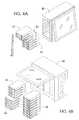
- FIGS. 8-11show different views of an alternative embodiment of the present invention that uses a thermally conductive elastomeric coupler to transfer heat away from the hard drives.
- the inventionrelates to a module containing multiple hard drives which can be inserted and removed as an organized set of hard drives into a receptacle.
- the receptacleprovides precision mechanical alignment and electrical connection of the set of hard drives into a hard drive connector backplane.
- the hard drive backplaneprovides for a power and signal interconnect so that they can be interconnected to all necessary components for proper operation of the computer.
- the systemprovides for the removal and insertion of a set of drives with the computer turned off or turned on and operating. Individual drives can be removed and replaced from the multiple hard drive module without the need to first remove the multiple hard disk module from its receptacle. This allows defective drives to be individually replaced while other hard drives within the module continue to function normally in the computer.
- the multiple hard drive moduleallow the hard drives to be precision spaced so that a predetermined air space exist between hard drives to provide for air flow for cooling the hard drives.
- Two guide rails attached to each hard drive in the moduleprecisely guide and align each hard drive into individual precision placed connectors on the receptacle backplane.
- a binder barloosely but positively attaches all hard drives to the modules organizer sleeve.
- the organizer sleeveallows the hard drive set to be handled, inserted, removed, transported, stored and managed as a set and does not interfere with the precision alignment rail function of each hard drive which allows the receptacle to individually align each hard drive for a precise docking of each hard drive to its corresponding backplane connector.
- Detaching the binder barallows one or more individual hard drives to be removed from the sleeve. This can be done regardless of weather the module is inserted into the receptacle and docked and actively operating in the backplane, or the module is removed from the receptacle and placed on a table.
- the receptacleincludes precision fabricated slots which mate with each hard drive's pair of rails and precisely align each hard drive to the receptacles connector backplane.
- the backplaneis designed in such as way that air can flow from the front of the drive to the rear of the drive with air flow allowed to freely flow through openings in the backplane and into the interior of the computer chassis where fans are typically located to assist with airflow.
- a retainer bar or retention latch systemsecurely and firmly hold the multiple hard drive module to the receptacle for transport while installed in the computer.
- the hard drive module receptacle systemallows the flexibility to have a single large multiple hard drive module plug into a single receptacle or alternatively multiple smaller modules continue a smaller number of hard drives to be concurrently installed into the same receptacle so long as the total number of drives in all modules does not exceed the total drive capacity of the receptacle.
- Individual drivesmay also be installed into the receptacle without being organized into a sleeve and be used in harmony with sets of drives organized into module sleeves.
- Hard drives selected for used in this inventionare assumed to be designed to be hot pluggable but this is not an absolute requirement, but may limit use to installing and removing after the power has been turned off. Furthermore the design is not limited to a particular capacity, technology type, interface type, physical size or number of drives. Further, airflow may be designed from front to back of the drives, but other configurations currently being implemented provide for side to side airflow.
- FIG. 1Ashows a perspective view of one example of the invention.
- the module 10includes: multiple hard drives 12 ; a sleeve 14 ; slide rails 16 for each hard drive; and a binder bar 18 .
- FIG. 1Bshows an exploded view of the same example.
- the sleeve 14is shown with multiple slots 19 in the sides of the sleeve 14 .
- the module 10serves to hold multiple hard drives 12 together as a single component that can be inserted into and removed from a computer.
- the individual hard drivesare held together with a binder bar 18 .
- the binder bar 18is attached onto each individual hard drive so that they are held together as a group.
- the binder bar 18is attached with a knurled knob to the side of each hard drive 12 . This allows the binder bar to be installed and removed by hand.
- FIG. 2shows an exploded view of a single hard drive 20 .
- a face plate 22is mounted on the front of the hard drive rails 24 a and 24 b which in turn are attached to hard drive 20 .
- the face plateserves as the attached point for the binder bar 18 shown previously in FIGS. 1A and 1B .
- two slide rails 24 a and 24 bare mounted on each side of the hard drive 20 .
- the face plate and slide railsare attached to the hard drive with screws.
- other types of attachment mechanismsmay be used in alternative embodiments.
- FIGS. 3A and 3Bshow different views of the module 32 as it is inserted into a computer 30 .
- FIG. 3Ashows a partially exploded view of the module 32 with a single hard drive 36 and the binder bar 39 detached from the module.
- the slide rails 38guide the hard drives 36 into the slots 37 of sleeve 34 .
- the slide rails 38extend outside the sides sleeve.
- the slide rails 38guide the module 32 into the computer 30 by match up with module guide slots inside the hard drive receptacle 33 that is located on the interior of the computer 30 .
- a retainer bar 35may be used to hold the module 32 in place.
- the module 32connects to the computer 30 through the hard drive receptacle 33 that is mounted with the computer.
- the receptacle 33contains a porous backplane (not shown) mounted in the rear which is designed such that air can flow freely from front to back of the module.
- the backplanemay be connected to the hard drive controller of the computer and required power supplies.
- the backplaneattaches to a RAID controller.
- the RAID (Redundant Array of Inexpensive Disks) systemis used to increase performance and provide fault tolerance for hard disk drives in computers.
- RAID level standardsare used with various levels of system redundancy and/or fault tolerance that are well known to those of skill in the art.
- the present inventionmay use RAID-0, RAID-1, or RAID-5 levels in various embodiments.
- the inventionmay use a JBOD (Just a Bunch of Disks) configuration that provides no system redundancy with the hard drives.
- JBODJust a Bunch of Disks
- FIGS. 4A-4Dshow examples of the present invention using modules of different numbers of hard drives. While the previous examples show a module with 8 hard drives, different sized modules may be used together in combination to replicate a larger capacity module.
- FIG. 4Ashows a similar computer 40 as shown previously in FIGS. 3A and 3B . However, two separate two-drive modules 42 are combined with a four-drive module 44 when inserted into the computer. This will duplicate the same performance as an eight-drive module but each smaller capacity module is an independent component which can be separately installed, removed and managed.
- FIG. 4Bshows another example of different capacity modules. In this example, an eight-drive module 46 is inserted into a server 48 along with two separate two-drive modules 44 . In this example, the modules are shown for use in a network server.
- the modulemay be inserted in a horizontal orientation as shown in FIGS. 4C and 4D .
- a pair of two-drive modules 42are combined with a four-drive module 44 and inserted in a horizontal receptacle 45 that is mounted within the computer.
- a porous backplane 47 and a retainer bar 49are also shown.
- the backplane 49is mounted in the rear of the receptacle 45 as shown in FIG. 4D . It provides a connection for the module to a drive controller as described previously.
- the retainer bar 49attaches over the modules to hold them in place within the sleeve 45 .
- the sleeveis merely an organizer for grouping the drives together in a module. It floats within the space of the receptacle of the computer system and it does not provide final precision alignment.
- the precision rails of the drivemate with the corresponding precision slots within the sleeve. This allows the individual hard drives to be inserted and dock with the backplane in the rear of the receptacle without damaging the connection mechanisms.
- the key advantage of the systemis to allow the each hard drive to independently float within the sleeve. This allows the modules and individual drives to be inserted and removed easily and quickly.
- the tolerance for the floating of the hard drive within the sleeveis between 0.03 and 0.06 inches. This is typically a looser tolerance that a design for computer hardware components that are inserted into component receptacles.
- FIG. 5shows a single hard drive 54 that is pulled out of the module 52 in a computer 50 after the retainer bar 58 and binder bar 56 are removed.
- the individual drives or even an entire modulemay be removed while the computer is in operation. This is known as “hot-pluggable” device.
- the removal or insertion of the driveswill not affect the operation of a working computer.
- the computerwill automatically reconfigure and reinstall the hard drives and continue operation.
- the hard drives used in some embodimentsmay be a “Serial Advanced Technology Attachment,” or “Serial ATA” (SATA) drive.
- SATASerial Advanced Technology Attachment
- Other embodimentsmay use a “Small Computer System Interface” (SCSI) drive that sometimes called a “skuzzy” drive or a more modern version of SCSI called Serial Attached SCSI (SAS).
- SCSISerial Computer System Interface
- SASSerial Attached SCSI
- SATASerial Attached SCSI
- a SATA driveis shown with a 500 GB storage capacity.
- the physical size of the hard drivesmay vary with different embodiments. Examples of hard drives that are used include a 2.5′′ drive and a 3.5′′ drive.
- the 3.5′′ drivehas an exterior width of 4.0 inches and an exterior thickness of 1.0 inches.
- the center to center distance between 3.5′′ drives 62 in a moduleis 1.25 inches with a 0.25 inch air gap 64 between drives.
- the 2.5′′ drivehas an exterior width of 70 mm and an exterior thickness of 9.5 mm.
- the center to center distance between 2.5′′ drives 66 in a moduleis 12.5 mm with a 3 mm air gap 68 between drives.
- FIG. 7shows a cut away view of an example of an internal cooling system.
- the hard drive module 72is installed in the computer 70 .
- a bank of multiple cooling fans 74are placed directly behind the module. The fans 74 draw cooler air from outside the computer in through the air gaps between the drives of the module. The air is then pulled out of the computer with exhaust fans 76 located opposite the module 72 and receptacle.
- Portable computersmany times need to operate at really high temperatures such as 60° C.
- One advantage of the present inventionis that fresh air is pulled through the air gap of the drives first before reaching the interior of the computer. This allows the hard drives to operate at or near the maximum of their specific temperature limits.
- the modulescould be used with other computer devices such as a portable workstation computer or a video system.
- a video systemis used to record and store digital video data. These systems are sometimes called a “digital film recorder (DFR)”, a “digital video recorder (DVR)” or a “digital disk recorder (DDR)”. These systems typically require a massive amount of data storage for a portable digital video system. It is fully intended that the invention could be used with any such device that needs a removable hard drive.
- FIGS. 8-11show different views of this embodiment.
- This embodimentis based on the use of low power 2.5′′ SATA or SAS drives 80 .
- other types of drivescould be used.
- the rails 82 of the module 84are modified to facilitate heat transfer from the hard disk drive to the chassis 86 .
- the backplane 88is no longer required to be porous to allow air flow. Instead, it may be solid.
- heatis transferred from the hard drive to the rails through a thermally conductive elastomeric coupler 90 which in turn conveys the heat to the metal chassis 92 of the module 84 . Heat is then transferred to a heat sink 94 at the rear of the module.
- the heat sinkmay be cooled by an optional fan 96 . In other embodiments, the fan is not present and natural convection air flow provides all of the necessary cooling.
- This embodimenthas the advantage of allowing the drives to be packed closer together since air flow between them is not required. This embodiment works especially well with both rotating type disk drives and solid state disk drives using flash memory technology.
Landscapes
- Engineering & Computer Science (AREA)
- Theoretical Computer Science (AREA)
- Human Computer Interaction (AREA)
- Physics & Mathematics (AREA)
- General Engineering & Computer Science (AREA)
- General Physics & Mathematics (AREA)
- Computer Hardware Design (AREA)
- Power Engineering (AREA)
- Cooling Or The Like Of Electrical Apparatus (AREA)
Abstract
Description
Claims (22)
Priority Applications (1)
| Application Number | Priority Date | Filing Date | Title |
|---|---|---|---|
| US12/476,056US8111514B2 (en) | 2006-04-21 | 2009-06-01 | Removable hard drive module for a computer with improved thermal performance |
Applications Claiming Priority (2)
| Application Number | Priority Date | Filing Date | Title |
|---|---|---|---|
| US11/409,296US7542295B2 (en) | 2006-04-21 | 2006-04-21 | Removable hard drive module for a computer |
| US12/476,056US8111514B2 (en) | 2006-04-21 | 2009-06-01 | Removable hard drive module for a computer with improved thermal performance |
Related Parent Applications (1)
| Application Number | Title | Priority Date | Filing Date |
|---|---|---|---|
| US11/409,296Continuation-In-PartUS7542295B2 (en) | 2006-04-21 | 2006-04-21 | Removable hard drive module for a computer |
Publications (2)
| Publication Number | Publication Date |
|---|---|
| US20090273898A1 US20090273898A1 (en) | 2009-11-05 |
| US8111514B2true US8111514B2 (en) | 2012-02-07 |
Family
ID=41256944
Family Applications (1)
| Application Number | Title | Priority Date | Filing Date |
|---|---|---|---|
| US12/476,056Active2026-09-19US8111514B2 (en) | 2006-04-21 | 2009-06-01 | Removable hard drive module for a computer with improved thermal performance |
Country Status (1)
| Country | Link |
|---|---|
| US (1) | US8111514B2 (en) |
Cited By (5)
| Publication number | Priority date | Publication date | Assignee | Title |
|---|---|---|---|---|
| US20110222234A1 (en)* | 2010-03-11 | 2011-09-15 | Xyratex Technology Limited | Storage enclosure, carrier and methods |
| US20130339989A1 (en)* | 2012-06-13 | 2013-12-19 | Hitachi-Lg Data Storage, Inc. | Archive device |
| US8724330B1 (en)* | 2012-12-28 | 2014-05-13 | International Business Machines Corporation | Variable latch to position a sub-chassis within a chassis |
| US8918576B2 (en) | 2012-04-24 | 2014-12-23 | Avago Technologies General Ip (Singapore) Pte. Ltd. | Selectively placing data in thermally constrained memory systems to dynamically adapt to changing environmental conditions |
| US9673567B1 (en)* | 2015-03-12 | 2017-06-06 | Juniper Networks, Inc. | Apparatus, system, and method for preventing electric shock during maintenance of telecommunication systems |
Families Citing this family (15)
| Publication number | Priority date | Publication date | Assignee | Title |
|---|---|---|---|---|
| CN102375699A (en)* | 2010-08-23 | 2012-03-14 | 英业达股份有限公司 | a memory system |
| CN103176518B (en)* | 2011-12-26 | 2016-08-03 | 广州美电恩智电子科技有限公司 | Hard disk module |
| US9470720B2 (en) | 2013-03-08 | 2016-10-18 | Sandisk Technologies Llc | Test system with localized heating and method of manufacture thereof |
| US10013033B2 (en) | 2013-06-19 | 2018-07-03 | Sandisk Technologies Llc | Electronic assembly with thermal channel and method of manufacture thereof |
| US9898056B2 (en)* | 2013-06-19 | 2018-02-20 | Sandisk Technologies Llc | Electronic assembly with thermal channel and method of manufacture thereof |
| US9313874B2 (en) | 2013-06-19 | 2016-04-12 | SMART Storage Systems, Inc. | Electronic system with heat extraction and method of manufacture thereof |
| US9158349B2 (en) | 2013-10-04 | 2015-10-13 | Sandisk Enterprise Ip Llc | System and method for heat dissipation |
| US9549457B2 (en) | 2014-02-12 | 2017-01-17 | Sandisk Technologies Llc | System and method for redirecting airflow across an electronic assembly |
| US9497889B2 (en) | 2014-02-27 | 2016-11-15 | Sandisk Technologies Llc | Heat dissipation for substrate assemblies |
| US9519319B2 (en) | 2014-03-14 | 2016-12-13 | Sandisk Technologies Llc | Self-supporting thermal tube structure for electronic assemblies |
| US9485851B2 (en)* | 2014-03-14 | 2016-11-01 | Sandisk Technologies Llc | Thermal tube assembly structures |
| US9348377B2 (en) | 2014-03-14 | 2016-05-24 | Sandisk Enterprise Ip Llc | Thermal isolation techniques |
| WO2016175799A1 (en)* | 2015-04-29 | 2016-11-03 | Hewlett Packard Enterprise Development Lp | Converged infrastructure manager |
| GB2571907A (en)* | 2018-01-16 | 2019-09-18 | Smethurst Nicholas | Configurable modular computer enclosure |
| CN115620756A (en)* | 2022-10-26 | 2023-01-17 | 苏州浪潮智能科技有限公司 | storage hard disk and computer |
Citations (37)
| Publication number | Priority date | Publication date | Assignee | Title |
|---|---|---|---|---|
| US5506750A (en)* | 1993-04-22 | 1996-04-09 | Bull S.A. | Mass memory subsystem having plates with pluralities of disk drives connected to central electronic cards |
| US5557499A (en)* | 1994-06-28 | 1996-09-17 | Ast Research, Inc. | Hard-disk drive tray assembly with pivotally rotatable front bezel |
| US5909358A (en)* | 1997-11-26 | 1999-06-01 | Todd Engineering Sales, Inc. | Snap-lock heat sink clip |
| US6069792A (en)* | 1997-09-16 | 2000-05-30 | Nelik; Jacob | Computer component cooling assembly |
| US6088221A (en)* | 1998-06-15 | 2000-07-11 | Compaq Computer Corporation | Hot-pluggable disk drive carrier assembly with no loose parts |
| US6157540A (en)* | 1998-07-27 | 2000-12-05 | Dell Usa, L.P. | Screwless front loading hard drive bracket |
| US6373696B1 (en)* | 1998-06-15 | 2002-04-16 | Compaq Computer Corporation | Hard drive cooling using finned heat sink and thermally conductive interface pad |
| US6473298B1 (en)* | 2000-08-30 | 2002-10-29 | Sun Microsystems, Inc. | Peripheral device storage system |
| US20020181197A1 (en)* | 2001-06-01 | 2002-12-05 | King-Tung Huang | Housing of data processing system with mechanism for easy removal and insertion of disk drive |
| US20020181194A1 (en)* | 2001-06-04 | 2002-12-05 | Sun Microsystems, Inc. | Computer bus rack having an increased density of card slots |
| US20030147219A1 (en)* | 2002-02-06 | 2003-08-07 | Shin Jiuh Corp. | Blade server module |
| US20030183373A1 (en)* | 2002-03-28 | 2003-10-02 | David Sarraf | Video game console cooler |
| US20030227752A1 (en)* | 2002-06-10 | 2003-12-11 | Yair Andrew John | Electronics assembly |
| US20040012921A1 (en)* | 2002-07-16 | 2004-01-22 | Fujitsu Limited | Module mounting/removing mechanism and disk array |
| US20040264145A1 (en)* | 2003-05-08 | 2004-12-30 | Miller Greg F. | Compact electronic component system and method |
| US6853548B2 (en)* | 2003-01-02 | 2005-02-08 | Quantum Corporation | 1U rack mount equipment enclosure with increased structural support |
| US20050083651A1 (en)* | 2002-05-31 | 2005-04-21 | Smith John V. | Method and apparatus for rack mounting computer components |
| US20050168940A1 (en)* | 2002-02-15 | 2005-08-04 | Microsoft Corporation | Controlling thermal, acoustic, and/or electromagnetic properties of a computing device |
| US20050174743A1 (en)* | 2002-01-21 | 2005-08-11 | Downing Robert W. | System for insertion and extraction of a printed circuit board module into and out of a subrack |
| US6957291B2 (en)* | 2001-03-29 | 2005-10-18 | Quantum Corporation | Removable disk storage array emulating tape library having backup and archive capability |
| US20050257232A1 (en)* | 2004-05-14 | 2005-11-17 | Fujitsu Limited | Enclosure structure of electronic equipment, and disk array apparatus |
| US20060002093A1 (en)* | 2004-07-02 | 2006-01-05 | Seagate Technology Llc | Engagement system for a module in an electronics cabinet |
| US6999307B2 (en)* | 2003-10-31 | 2006-02-14 | Inventec Corporation | Disk drive anchoring mechanism |
| US20060050487A1 (en)* | 2004-09-09 | 2006-03-09 | Tatung Co., Ltd. | Computer server |
| US7035096B2 (en)* | 2003-10-31 | 2006-04-25 | Hewlett-Packard Development Company, L.P. | Locking mechanism for removable components |
| US7092245B2 (en)* | 2004-07-16 | 2006-08-15 | Evserv Tech Corporation | Circuit board group for electrically coupling electronic devices |
| US20060198112A1 (en)* | 2001-06-13 | 2006-09-07 | Apple Computer, Inc. | Ultra compact computer arrangement |
| US20060221579A1 (en)* | 2005-03-31 | 2006-10-05 | Yuan-Chen Liang | Blade server system |
| US20060232930A1 (en)* | 2005-04-13 | 2006-10-19 | Dell Products L.P. | Method and apparatus for cooling an information handling system |
| US20060250766A1 (en)* | 2005-05-06 | 2006-11-09 | Blaalid Jeffrey S | Apparatus for removably securing storage components in an enclosure |
| US7158380B2 (en)* | 2005-03-25 | 2007-01-02 | Scientific-Atlanta, Inc. | Heatsink for digital video recorder |
| US7200008B1 (en)* | 2004-07-01 | 2007-04-03 | Bhugra Kern S | Multi-depth drive enclosure |
| US7280352B2 (en)* | 2004-06-07 | 2007-10-09 | Sun Microsystems, Inc. | Drive carrier |
| US20070293137A1 (en)* | 2006-06-20 | 2007-12-20 | International Business Machines Corporation | Acoustic noise reduction using airflow management |
| US7312999B1 (en)* | 2005-04-29 | 2007-12-25 | Network Appliance, Inc. | High density drive chassis assembly |
| US20080049388A1 (en)* | 2006-04-27 | 2008-02-28 | Lsi Logic Corporation | Thermal control through a channel structure |
| US7542295B2 (en)* | 2006-04-21 | 2009-06-02 | Maxvision Corporation | Removable hard drive module for a computer |
- 2009
- 2009-06-01USUS12/476,056patent/US8111514B2/enactiveActive
Patent Citations (37)
| Publication number | Priority date | Publication date | Assignee | Title |
|---|---|---|---|---|
| US5506750A (en)* | 1993-04-22 | 1996-04-09 | Bull S.A. | Mass memory subsystem having plates with pluralities of disk drives connected to central electronic cards |
| US5557499A (en)* | 1994-06-28 | 1996-09-17 | Ast Research, Inc. | Hard-disk drive tray assembly with pivotally rotatable front bezel |
| US6069792A (en)* | 1997-09-16 | 2000-05-30 | Nelik; Jacob | Computer component cooling assembly |
| US5909358A (en)* | 1997-11-26 | 1999-06-01 | Todd Engineering Sales, Inc. | Snap-lock heat sink clip |
| US6088221A (en)* | 1998-06-15 | 2000-07-11 | Compaq Computer Corporation | Hot-pluggable disk drive carrier assembly with no loose parts |
| US6373696B1 (en)* | 1998-06-15 | 2002-04-16 | Compaq Computer Corporation | Hard drive cooling using finned heat sink and thermally conductive interface pad |
| US6157540A (en)* | 1998-07-27 | 2000-12-05 | Dell Usa, L.P. | Screwless front loading hard drive bracket |
| US6473298B1 (en)* | 2000-08-30 | 2002-10-29 | Sun Microsystems, Inc. | Peripheral device storage system |
| US6957291B2 (en)* | 2001-03-29 | 2005-10-18 | Quantum Corporation | Removable disk storage array emulating tape library having backup and archive capability |
| US20020181197A1 (en)* | 2001-06-01 | 2002-12-05 | King-Tung Huang | Housing of data processing system with mechanism for easy removal and insertion of disk drive |
| US20020181194A1 (en)* | 2001-06-04 | 2002-12-05 | Sun Microsystems, Inc. | Computer bus rack having an increased density of card slots |
| US20060198112A1 (en)* | 2001-06-13 | 2006-09-07 | Apple Computer, Inc. | Ultra compact computer arrangement |
| US20050174743A1 (en)* | 2002-01-21 | 2005-08-11 | Downing Robert W. | System for insertion and extraction of a printed circuit board module into and out of a subrack |
| US20030147219A1 (en)* | 2002-02-06 | 2003-08-07 | Shin Jiuh Corp. | Blade server module |
| US20050168940A1 (en)* | 2002-02-15 | 2005-08-04 | Microsoft Corporation | Controlling thermal, acoustic, and/or electromagnetic properties of a computing device |
| US20030183373A1 (en)* | 2002-03-28 | 2003-10-02 | David Sarraf | Video game console cooler |
| US20050083651A1 (en)* | 2002-05-31 | 2005-04-21 | Smith John V. | Method and apparatus for rack mounting computer components |
| US20030227752A1 (en)* | 2002-06-10 | 2003-12-11 | Yair Andrew John | Electronics assembly |
| US20040012921A1 (en)* | 2002-07-16 | 2004-01-22 | Fujitsu Limited | Module mounting/removing mechanism and disk array |
| US6853548B2 (en)* | 2003-01-02 | 2005-02-08 | Quantum Corporation | 1U rack mount equipment enclosure with increased structural support |
| US20040264145A1 (en)* | 2003-05-08 | 2004-12-30 | Miller Greg F. | Compact electronic component system and method |
| US6999307B2 (en)* | 2003-10-31 | 2006-02-14 | Inventec Corporation | Disk drive anchoring mechanism |
| US7035096B2 (en)* | 2003-10-31 | 2006-04-25 | Hewlett-Packard Development Company, L.P. | Locking mechanism for removable components |
| US20050257232A1 (en)* | 2004-05-14 | 2005-11-17 | Fujitsu Limited | Enclosure structure of electronic equipment, and disk array apparatus |
| US7280352B2 (en)* | 2004-06-07 | 2007-10-09 | Sun Microsystems, Inc. | Drive carrier |
| US7200008B1 (en)* | 2004-07-01 | 2007-04-03 | Bhugra Kern S | Multi-depth drive enclosure |
| US20060002093A1 (en)* | 2004-07-02 | 2006-01-05 | Seagate Technology Llc | Engagement system for a module in an electronics cabinet |
| US7092245B2 (en)* | 2004-07-16 | 2006-08-15 | Evserv Tech Corporation | Circuit board group for electrically coupling electronic devices |
| US20060050487A1 (en)* | 2004-09-09 | 2006-03-09 | Tatung Co., Ltd. | Computer server |
| US7158380B2 (en)* | 2005-03-25 | 2007-01-02 | Scientific-Atlanta, Inc. | Heatsink for digital video recorder |
| US20060221579A1 (en)* | 2005-03-31 | 2006-10-05 | Yuan-Chen Liang | Blade server system |
| US20060232930A1 (en)* | 2005-04-13 | 2006-10-19 | Dell Products L.P. | Method and apparatus for cooling an information handling system |
| US7312999B1 (en)* | 2005-04-29 | 2007-12-25 | Network Appliance, Inc. | High density drive chassis assembly |
| US20060250766A1 (en)* | 2005-05-06 | 2006-11-09 | Blaalid Jeffrey S | Apparatus for removably securing storage components in an enclosure |
| US7542295B2 (en)* | 2006-04-21 | 2009-06-02 | Maxvision Corporation | Removable hard drive module for a computer |
| US20080049388A1 (en)* | 2006-04-27 | 2008-02-28 | Lsi Logic Corporation | Thermal control through a channel structure |
| US20070293137A1 (en)* | 2006-06-20 | 2007-12-20 | International Business Machines Corporation | Acoustic noise reduction using airflow management |
Cited By (7)
| Publication number | Priority date | Publication date | Assignee | Title |
|---|---|---|---|---|
| US20110222234A1 (en)* | 2010-03-11 | 2011-09-15 | Xyratex Technology Limited | Storage enclosure, carrier and methods |
| US8599550B2 (en)* | 2010-03-11 | 2013-12-03 | Xyratex Technology Limited | Storage enclosure, carrier and methods |
| US8918576B2 (en) | 2012-04-24 | 2014-12-23 | Avago Technologies General Ip (Singapore) Pte. Ltd. | Selectively placing data in thermally constrained memory systems to dynamically adapt to changing environmental conditions |
| US20130339989A1 (en)* | 2012-06-13 | 2013-12-19 | Hitachi-Lg Data Storage, Inc. | Archive device |
| US9190101B2 (en)* | 2012-06-13 | 2015-11-17 | Hitachi-Lg Data Storage, Inc. | Archive device |
| US8724330B1 (en)* | 2012-12-28 | 2014-05-13 | International Business Machines Corporation | Variable latch to position a sub-chassis within a chassis |
| US9673567B1 (en)* | 2015-03-12 | 2017-06-06 | Juniper Networks, Inc. | Apparatus, system, and method for preventing electric shock during maintenance of telecommunication systems |
Also Published As
| Publication number | Publication date |
|---|---|
| US20090273898A1 (en) | 2009-11-05 |
Similar Documents
| Publication | Publication Date | Title |
|---|---|---|
| US8111514B2 (en) | Removable hard drive module for a computer with improved thermal performance | |
| US7542295B2 (en) | Removable hard drive module for a computer | |
| US10001819B2 (en) | Dual-sided rackmount modular data processing assembly | |
| US9746886B2 (en) | Solid state storage system | |
| US8508928B2 (en) | Incorporation of multiple, 2.5-inch or smaller hard disk drives into a single drive carrier with a single midplane or baseboard connector | |
| US7583507B2 (en) | High density array system having multiple storage units with active movable media drawers | |
| US9767856B2 (en) | High density storage device system | |
| US20100049914A1 (en) | RAID Enhanced solid state drive | |
| US20130170129A1 (en) | Systems and methods for providing a dynamic electronic storage unit | |
| US20180192536A1 (en) | Reduced depth data storage assembly and rack server | |
| US9519318B2 (en) | Carrier with multiple storage devices having different form factors | |
| JP2022511836A (en) | Electronic devices with parallel backplanes and storage devices with parallel backplanes | |
| WO2007115206A2 (en) | High density array system with active storage media support structures | |
| US20210224211A1 (en) | Storage drive adapter | |
| CN108196644A (en) | 4U storage server systems with hard disk backboard | |
| US9280174B2 (en) | Data storage device enclosure and module | |
| US7894208B1 (en) | Server module | |
| US20050289217A1 (en) | Low cost flexible network accessed storage architecture | |
| US10244667B2 (en) | Storage apparatus and storage device management program | |
| US7505261B2 (en) | Electrical-optical signal conversion for automated storage systems | |
| US20220100233A1 (en) | Storage device carriers | |
| US9122419B2 (en) | Data storage unit with internal storage area network switch module and redundant data storage system including such data storage unit | |
| GB2508178A (en) | Module for data storage devices with means by which the data storage device can be accessed from outside the module. | |
| MX2014005708A (en) | Systems and methods for providing a dynamic electronic storage unit. |
Legal Events
| Date | Code | Title | Description |
|---|---|---|---|
| AS | Assignment | Owner name:MAXVISION CORPORATION, ALABAMA Free format text:ASSIGNMENT OF ASSIGNORS INTEREST;ASSIGNOR:IMSAND, BRUCE;REEL/FRAME:022971/0673 Effective date:20090611 | |
| STCF | Information on status: patent grant | Free format text:PATENTED CASE | |
| AS | Assignment | Owner name:RPC GENESIS, LLC, ALABAMA Free format text:SECURITY AGREEMENT;ASSIGNOR:MAX VISION, LLC;REEL/FRAME:028835/0893 Effective date:20120803 | |
| AS | Assignment | Owner name:RUGGED PORTABLE COMPUTERS, LLC, ALABAMA Free format text:ASSIGNMENT OF ASSIGNORS INTEREST;ASSIGNOR:RPC GENESIS, LLC;REEL/FRAME:029631/0929 Effective date:20120901 | |
| FPAY | Fee payment | Year of fee payment:4 | |
| MAFP | Maintenance fee payment | Free format text:PAYMENT OF MAINTENANCE FEE, 8TH YR, SMALL ENTITY (ORIGINAL EVENT CODE: M2552); ENTITY STATUS OF PATENT OWNER: SMALL ENTITY Year of fee payment:8 | |
| MAFP | Maintenance fee payment | Free format text:PAYMENT OF MAINTENANCE FEE, 12TH YR, SMALL ENTITY (ORIGINAL EVENT CODE: M2553); ENTITY STATUS OF PATENT OWNER: SMALL ENTITY Year of fee payment:12 |