US8111147B2 - Lane departure warning and change assist system utilizing active materials - Google Patents
Lane departure warning and change assist system utilizing active materialsDownload PDFInfo
- Publication number
- US8111147B2 US8111147B2US12/119,505US11950508AUS8111147B2US 8111147 B2US8111147 B2US 8111147B2US 11950508 AUS11950508 AUS 11950508AUS 8111147 B2US8111147 B2US 8111147B2
- Authority
- US
- United States
- Prior art keywords
- lane
- vehicle
- signal
- controller
- change
- Prior art date
- Legal status (The legal status is an assumption and is not a legal conclusion. Google has not performed a legal analysis and makes no representation as to the accuracy of the status listed.)
- Expired - Fee Related, expires
Links
- 230000008859changeEffects0.000titleclaimsabstractdescription46
- 239000011149active materialSubstances0.000titleclaimsabstractdescription17
- 230000004913activationEffects0.000claimsabstractdescription17
- 230000003213activating effectEffects0.000claimsabstractdescription3
- 239000012530fluidSubstances0.000claimsdescription30
- 230000005291magnetic effectEffects0.000claimsdescription12
- 230000002441reversible effectEffects0.000claimsdescription9
- 238000000034methodMethods0.000claimsdescription7
- 230000000737periodic effectEffects0.000claimsdescription3
- 230000008878couplingEffects0.000description9
- 238000010168coupling processMethods0.000description9
- 238000005859coupling reactionMethods0.000description9
- 239000000463materialSubstances0.000description9
- 239000002245particleSubstances0.000description8
- 238000010586diagramMethods0.000description7
- XEEYBQQBJWHFJM-UHFFFAOYSA-NIronChemical compound[Fe]XEEYBQQBJWHFJM-UHFFFAOYSA-N0.000description5
- 229920001971elastomerPolymers0.000description5
- 239000000806elastomerSubstances0.000description5
- PXHVJJICTQNCMI-UHFFFAOYSA-NNickelChemical compound[Ni]PXHVJJICTQNCMI-UHFFFAOYSA-N0.000description4
- 230000008901benefitEffects0.000description3
- 230000000694effectsEffects0.000description3
- 230000000007visual effectEffects0.000description3
- 229910017052cobaltInorganic materials0.000description2
- 239000010941cobaltSubstances0.000description2
- GUTLYIVDDKVIGB-UHFFFAOYSA-Ncobalt atomChemical compound[Co]GUTLYIVDDKVIGB-UHFFFAOYSA-N0.000description2
- 229920001746electroactive polymerPolymers0.000description2
- SZVJSHCCFOBDDC-UHFFFAOYSA-Nferrosoferric oxideChemical compoundO=[Fe]O[Fe]O[Fe]=OSZVJSHCCFOBDDC-UHFFFAOYSA-N0.000description2
- 230000004907fluxEffects0.000description2
- 230000006870functionEffects0.000description2
- 229910052742ironInorganic materials0.000description2
- 229910052759nickelInorganic materials0.000description2
- 229920000642polymerPolymers0.000description2
- 238000010008shearingMethods0.000description2
- VYZAMTAEIAYCRO-UHFFFAOYSA-NChromiumChemical compound[Cr]VYZAMTAEIAYCRO-UHFFFAOYSA-N0.000description1
- 229910000531Co alloyInorganic materials0.000description1
- RYGMFSIKBFXOCR-UHFFFAOYSA-NCopperChemical compound[Cu]RYGMFSIKBFXOCR-UHFFFAOYSA-N0.000description1
- 229910000976Electrical steelInorganic materials0.000description1
- 229910000640Fe alloyInorganic materials0.000description1
- PWHULOQIROXLJO-UHFFFAOYSA-NManganeseChemical compound[Mn]PWHULOQIROXLJO-UHFFFAOYSA-N0.000description1
- ZOKXTWBITQBERF-UHFFFAOYSA-NMolybdenumChemical compound[Mo]ZOKXTWBITQBERF-UHFFFAOYSA-N0.000description1
- 229910000990Ni alloyInorganic materials0.000description1
- XUIMIQQOPSSXEZ-UHFFFAOYSA-NSiliconChemical compound[Si]XUIMIQQOPSSXEZ-UHFFFAOYSA-N0.000description1
- 229910052782aluminiumInorganic materials0.000description1
- XAGFODPZIPBFFR-UHFFFAOYSA-NaluminiumChemical compound[Al]XAGFODPZIPBFFR-UHFFFAOYSA-N0.000description1
- 229910001567cementiteInorganic materials0.000description1
- 239000000919ceramicSubstances0.000description1
- 238000006243chemical reactionMethods0.000description1
- 229910052804chromiumInorganic materials0.000description1
- 239000011651chromiumSubstances0.000description1
- 229940090961chromium dioxideDrugs0.000description1
- IAQWMWUKBQPOIY-UHFFFAOYSA-Nchromium(4+);oxygen(2-)Chemical compound[O-2].[O-2].[Cr+4]IAQWMWUKBQPOIY-UHFFFAOYSA-N0.000description1
- AYTAKQFHWFYBMA-UHFFFAOYSA-Nchromium(IV) oxideInorganic materialsO=[Cr]=OAYTAKQFHWFYBMA-UHFFFAOYSA-N0.000description1
- 238000004891communicationMethods0.000description1
- 239000002131composite materialSubstances0.000description1
- 230000006835compressionEffects0.000description1
- 238000007906compressionMethods0.000description1
- 229910052802copperInorganic materials0.000description1
- 239000010949copperSubstances0.000description1
- 230000008030eliminationEffects0.000description1
- 238000003379elimination reactionMethods0.000description1
- 238000005265energy consumptionMethods0.000description1
- 230000005294ferromagnetic effectEffects0.000description1
- 239000000446fuelSubstances0.000description1
- 230000020169heat generationEffects0.000description1
- 229910001337iron nitrideInorganic materials0.000description1
- UQSXHKLRYXJYBZ-UHFFFAOYSA-Niron oxideInorganic materials[Fe]=OUQSXHKLRYXJYBZ-UHFFFAOYSA-N0.000description1
- 235000013980iron oxideNutrition0.000description1
- VBMVTYDPPZVILR-UHFFFAOYSA-Niron(2+);oxygen(2-)Chemical class[O-2].[Fe+2]VBMVTYDPPZVILR-UHFFFAOYSA-N0.000description1
- JEIPFZHSYJVQDO-UHFFFAOYSA-Niron(III) oxideInorganic materialsO=[Fe]O[Fe]=OJEIPFZHSYJVQDO-UHFFFAOYSA-N0.000description1
- 230000005381magnetic domainEffects0.000description1
- 229910052748manganeseInorganic materials0.000description1
- 239000011572manganeseSubstances0.000description1
- 238000004519manufacturing processMethods0.000description1
- 239000011159matrix materialSubstances0.000description1
- 239000000203mixtureSubstances0.000description1
- 230000004048modificationEffects0.000description1
- 238000012986modificationMethods0.000description1
- 229910052750molybdenumInorganic materials0.000description1
- 239000011733molybdenumSubstances0.000description1
- 239000002086nanomaterialSubstances0.000description1
- 239000003973paintSubstances0.000description1
- 230000005298paramagnetic effectEffects0.000description1
- 230000003071parasitic effectEffects0.000description1
- 230000009467reductionEffects0.000description1
- 230000004044responseEffects0.000description1
- 238000009420retrofittingMethods0.000description1
- 230000001953sensory effectEffects0.000description1
- 229910001285shape-memory alloyInorganic materials0.000description1
- 229910052710siliconInorganic materials0.000description1
- 239000010703siliconSubstances0.000description1
- 239000002520smart materialSubstances0.000description1
- 239000007787solidSubstances0.000description1
- 239000010935stainless steelSubstances0.000description1
- 229910001220stainless steelInorganic materials0.000description1
- 239000000126substanceSubstances0.000description1
- 230000001629suppressionEffects0.000description1
- 239000000725suspensionSubstances0.000description1
- 229920001169thermoplasticPolymers0.000description1
- 239000004416thermosoftening plasticSubstances0.000description1
- WFKWXMTUELFFGS-UHFFFAOYSA-NtungstenChemical compound[W]WFKWXMTUELFFGS-UHFFFAOYSA-N0.000description1
- 229910052721tungstenInorganic materials0.000description1
- 239000010937tungstenSubstances0.000description1
- 229910052720vanadiumInorganic materials0.000description1
- LEONUFNNVUYDNQ-UHFFFAOYSA-Nvanadium atomChemical compound[V]LEONUFNNVUYDNQ-UHFFFAOYSA-N0.000description1
Images


Classifications
- B—PERFORMING OPERATIONS; TRANSPORTING
- B60—VEHICLES IN GENERAL
- B60Q—ARRANGEMENT OF SIGNALLING OR LIGHTING DEVICES, THE MOUNTING OR SUPPORTING THEREOF OR CIRCUITS THEREFOR, FOR VEHICLES IN GENERAL
- B60Q9/00—Arrangement or adaptation of signal devices not provided for in one of main groups B60Q1/00 - B60Q7/00, e.g. haptic signalling
- B—PERFORMING OPERATIONS; TRANSPORTING
- B62—LAND VEHICLES FOR TRAVELLING OTHERWISE THAN ON RAILS
- B62D—MOTOR VEHICLES; TRAILERS
- B62D15/00—Steering not otherwise provided for
- B62D15/02—Steering position indicators ; Steering position determination; Steering aids
- B62D15/025—Active steering aids, e.g. helping the driver by actively influencing the steering system after environment evaluation
- B—PERFORMING OPERATIONS; TRANSPORTING
- B62—LAND VEHICLES FOR TRAVELLING OTHERWISE THAN ON RAILS
- B62D—MOTOR VEHICLES; TRAILERS
- B62D15/00—Steering not otherwise provided for
- B62D15/02—Steering position indicators ; Steering position determination; Steering aids
- B62D15/029—Steering assistants using warnings or proposing actions to the driver without influencing the steering system
- B—PERFORMING OPERATIONS; TRANSPORTING
- B60—VEHICLES IN GENERAL
- B60T—VEHICLE BRAKE CONTROL SYSTEMS OR PARTS THEREOF; BRAKE CONTROL SYSTEMS OR PARTS THEREOF, IN GENERAL; ARRANGEMENT OF BRAKING ELEMENTS ON VEHICLES IN GENERAL; PORTABLE DEVICES FOR PREVENTING UNWANTED MOVEMENT OF VEHICLES; VEHICLE MODIFICATIONS TO FACILITATE COOLING OF BRAKES
- B60T2201/00—Particular use of vehicle brake systems; Special systems using also the brakes; Special software modules within the brake system controller
- B60T2201/08—Lane monitoring; Lane Keeping Systems
- B60T2201/082—Lane monitoring; Lane Keeping Systems using alarm actuation
Definitions
- the present inventionrelates to lane departure warning and lane change assist systems adapted for use with a vehicle, and more particularly, to a lane departure warning and lane change assist system that utilizes active material activation, and more preferably, utilizes a Magneto-Rheological Hydraulic Power Steering (MR-HPS) system to effect warning.
- MR-HPSMagneto-Rheological Hydraulic Power Steering
- Lane departure warning and lane change assist (LDW/LCA) systemshave been developed to assist operators (i.e. drivers) in maintaining proper lane alignment by alerting the operator to a possible unintentional lane departure and/or autonomously acting to keep the vehicle within the lane.
- LDW systemsprovide timely warnings prior to lane departure.
- Lane change assist systemswarn the driver of an approaching vehicle traveling in the direction of the host vehicle in the adjacent lanes when a lane change by the driver could pose a potential danger.
- LDW/LCA systemsoffer effective warning alerts for vehicles in central lanes, wherein shoulder methods would be ineffective.
- LDW systemstypically utilize at least one radar/lidar, DGPS/INS and digital map, or camera/video processing sensor to detect the lane markings (or road edges) that delineate a lane boundary.
- the detected lane-marking rangeis typically used to determine the lateral position of the vehicle in the lane (i.e., vehicle in-lane position), and a parameter time-to-lane-crossing (TTLC) is calculated based on the in-lane position and the motion of the vehicle. If the TTLC is smaller than a predefined threshold, a warning is typically issued.
- Other lateral support systemssuch as lane keeping (LK) systems, have similarly been developed.
- a combination of haptic and visual means, wherein the visual alert is secondary,has been found to present an effective modality of warning a human operator.
- a common type of haptic alertis to use a haptic seat; this type of system, however, has been found to add to the cost of the vehicle.
- a second effective haptic alertis to vibrate the steering wheel.
- EPSElectrical Power Steering
- EHPSelectro-hydraulic power steering
- MR-HPS systemshave been recently implemented to provide more energy efficient and adjustable power steering control in comparison to traditional hydraulic, EHPS or EPS embodiments.
- This type of power steering systemutilizes a low current coil to generate a magnetic field across a reservoir of MR fluid, which causes a reversible change in the viscosity of the fluid, and thereby controls the pump speed. By controlling the torque (proportional to current) as a function of vehicle speed, the variable power assist is obtained.
- the present inventionutilizes an active material element, and more preferably, the activated response of an MR-HPS system to provide a haptic warning to an operator through the steering wheel.
- an improved lane departure warning and lane change assist systemis presented that utilizes the reversibility of active materials to drive a haptic alert instead of an electric motor or a purely hydraulic system.
- the novel systemis useful for reducing the likelihood of accidents caused by improper (i.e., unintended and/or dangerous) lane changes.
- a preferred embodiment of the systemis further configured to provide a lane departure warning system that receives operator or vehicular input and terminates the production of the warning based on the input.
- a first aspect of the present inventionconcerns a lane-departure warning and/or lane change assist system adapted for use by an operator and with a vehicle traveling within a lane delineated by at least one lane-marking.
- the systemincludes at least one sensor operable to detect the location of the lane-marking or object relative to the vehicle, and a controller communicatively coupled to the sensor.
- the controlleris configured to execute a warning algorithm, wherein the controller determines a spatial relationship between the vehicle and lane-marking, compares the relationship to a predetermined threshold, and causes an activation signal to be generated when the threshold is exceeded or an object is detected.
- a warning devicehaving an active material element coupled to the controller is included and configured to generate an alert when the element is activated by the signal.
- a second aspect of the inventionconcerns a method of alerting the operator to an improper lane change, wherein the vehicle includes a module engaged by the operator.
- the methodincludes securing an active material relative to the module, such that a reversible characteristic of the material causes a module condition detectable by the operator.
- the existence of an approaching vehicle in the direction of host vehicle travel in an adjacent laneis determined so as to further determine a spatial relationship between the host vehicle and the approaching vehicle.
- the position of a lane-marking relative to the host vehiclecan also be determined, so as to further determine a spatial relationship between the marking and host vehicle.
- the relationshipis compared to a threshold, an activation signal is generated when the relationship exceeds the threshold, and the signal is transmitted, so as to active the material.
- the characteristicis thereby changed by activating the material, and the module condition is modified by changing the characteristic. Finally, the operator is alerted through the change in module condition.
- the present inventionprovides a number of advantages over the prior art, including, for example, providing a readily implemented system in vehicles having existing MR-HPS systems, and avoiding the additional cost for warning generation.
- the inventive systemprovides the benefits of lowering energy consumption to effect a warning, thereby reducing the load upon the charging system, increasing reliability by reducing the number of moving parts, reducing the mass of the vehicle by eliminating electro-mechanical components, and providing modality in preventing improper lane changes, in comparison to conventional electrically driven steering wheel warning (e.g., vibration) systems.
- FIG. 1is a plan view of a vehicle traveling within a lane, particularly illustrating lane-markings and an exemplary warning zone, in accordance with a preferred embodiment of the present invention
- FIG. 2is an elevational view of a vehicle traveling within a lane, particularly illustrating a lane-marking, operator, and DGPS system, in accordance with a preferred embodiment of the present invention
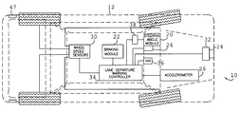
- FIG. 3is a plan view of a host vehicle having implemented a preferred lane-departure warning system, in accordance with the present invention, particularly illustrating the general components of the system;
- FIG. 4is an elevational view of the interior of a vehicle, particularly illustrating a steering wheel and HVI monitor, in accordance with a preferred embodiment of the invention
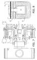
- FIG. 5is a generalized elevational view of a steering column, and modified MR-HPS system, particularly illustrating the MR fluid and low current coil;
- FIG. 5 ais a side elevational view of the fluid pump shown in FIG. 5 , particularly illustrating the coil;
- FIG. 5 bis a generalized elevational view of the steering column and MR-HPS system shown in FIG. 5 , after activation of the MR fluid;
- FIG. 6is a schematic diagram of the system 10 , particularly illustrating an MR-HPS coupling, a hydraulic power steering pump module, engine accessory belt-drive, controller, amplifier, and power source, in accordance with a preferred embodiment of the invention
- FIG. 7is a cross-sectional view of an MR-HPS coupling having inner and outer rotors, a low current coil, and a layer of MR fluid stored between the inner and outer rotors, in accordance with a preferred embodiment of the invention
- FIG. 8is a schematic plan view of the coil shown in FIG. 7 , particularly illustrating magnetic field lines generated when a current is passed through the coil;
- FIG. 9is a line diagram depicting a sinusoidal activation signal profile, in accordance with a preferred embodiment of the invention.
- FIG. 9 ais a line diagram depicting a trapezoidal activation signal profile, having ramp up and down periods, in accordance with a preferred embodiment of the invention.
- FIG. 9 bis a line diagram depicting a parabolic activation signal profile, in accordance with a preferred embodiment of the invention.
- FIG. 9 cis a line diagram depicting a periodic spike activation signal profile, in accordance with a preferred embodiment of the invention.
- FIG. 9 dis a line diagram depicting a double spike activation signal profile, in accordance with a preferred embodiment of the invention.
- FIG. 9 eis a line diagram of the profile shown in FIG. 6 d , wherein the wave cycles are stair-stepped to provide increasing amplitude.
- the present inventionconcerns an improved lane departure warning and/or lane change assist system 10 adapted for use with a host vehicle 12 traveling within a lane (e.g., of a thoroughfare or road), and by a human operator 14 ( FIGS. 1 and 2 ), wherein the lane may be delineated by at least one lane-marking 16 .
- the system 10is described and illustrated herein with respect to an automobile, however, it is certainly within the ambit of the present invention to utilize the system 10 with other lane-based transportation machines, such as boats and airplanes taxiing on runways.
- lane-markingincludes visible elements such as highly reflective paint or thermoplastic stripes (whether in continuous or dashed line-type), curbs, medians, reflectors, and otherwise distinguishable edges of pavement, or invisible elements embedded under pavement such as magnetic elements.
- the system 10is configured to detect the position of the vehicle 12 relative to a lane marking 16 of interest (i.e., the nearest and/or approaching lane marking).
- the system 10is configured to determine a spatial relationship, such as the distance between the lane-marking 16 and vehicle 12 (as measured from the sensor position), the time-to-lane-cross (TTLC) relative to the marking 16 , or the change in distance between the vehicle 12 and approaching traffic adjacent the vehicle 12 . If the relationship exceeds a predetermined warning threshold (i.e., the distance or TTLC is less than a predefined safe value), the system 10 is configured to alert the operator 14 to a potential improper lane change or lane deviation.
- a predetermined warning thresholdi.e., the distance or TTLC is less than a predefined safe value
- the system 10is further configured to deactivate the warning, once the vehicle 12 has completed the lane change or a warning compression criteria is activated, and as such, more preferably presents a warning zone 18 defined by earliest and latest warning lines 18 a,b ( FIG. 1 ).
- the host vehicle 12is further equipped with steering wheel and braking modules 20 , 22 as are conventionally known in the art; and the system 10 includes a forward-looking camera 24 , a steering angle sensor 26 , an accelerometer 28 , wheel speed sensors 30 , a video/image-processing unit 32 , a warning algorithm controller 34 , and a human-vehicle interface (HVI) 36 ( FIG. 3 ).
- the system 10is drivenly coupled to and the vehicle 12 further includes a magneto-rheological hydraulic power steering subsystem (MR-HPS) 38 that is configured to engage, so as to provide adjustable steering assistance to, the steering wheel module 20 .
- MR-HPSmagneto-rheological hydraulic power steering subsystem
- the controller 34is configured to perform a warning algorithm that starts by reading operator and/or vehicular input regarding system operation (e.g., on/off, driving style, threshold limits, etc.). Next the controller 34 receives sensory data, such as frames of vision images from the camera 24 , signals from exterior object (e.g., blind-spot) sensors, and signals from on-board condition sensors, such as the accelerometer 28 . In this configuration, for example, an image-processing sub-routine is then performed to identify lane markings 16 within the vision image data. If no markings are determined, it is within a preferred embodiment of the invention to utilize default markings, virtually positioned at a predetermined maximum lateral spacing from the vehicle. As such, the preferred system 10 is further configured to determine the in-lane position of the vehicle 12 , and preferably the centerline of the traveled lane.
- GPSGlobal Positioning System
- the GPS 40is used to provide the absolute position of the vehicle in earth inertial coordinates, utilizing a receiver 42 and at least four communicating satellites 44 ( FIG. 2 ), as is known in the art.
- the vehicle heading and in-lane positioncan be further determined using a map database 46 , whereby the GPS 40 correlates the coordinates of each position with one of a plurality of map position points.
- other signal sources located at control pointscould be communicatively coupled to the receiver 42 , and other coordinate systems based on a variety of geodetic datum, units, projections, and references could be utilized to pinpoint the vehicle 12 .
- the database 46preferably includes a plurality of digital maps built from GPS data of actual geographic roadways and thoroughfares.
- the preferred database 46further includes and is cooperatively configured to provide the controller 34 with precise lane-marking locations.
- at least a portion of the pointspreferably include ID links that enable correlation with indicia conveying an actual condition of the thoroughfare at the given location.
- the indiciapreferably include the identification of a lane-marking point, and/or roadway heading at the point.
- the indiciamay include a description of the thoroughfare (e.g., “3N2S,” for a description of three north bound and two southbound lanes) that could be utilized by the controller 34 to estimate lane-marking locations.
- the database 46may be stored in the system 10 by conventional storage means, such as a DVD-ROM, internal hard disk, or removable memory card, and/or periodically updated through wireless communication with a third party.
- the wheel speed sensors 30may be used to provide the vehicle velocity, and the TTLC is determined based on the in-lane position of the vehicle 12 and its velocity. If the TTLC exceeds the predetermined threshold, a warning is caused to be issued; otherwise, the algorithm resets and new data is received preferably on a continuous basis, as it is appreciated that lane changes/deviations usually occur over short durations.
- the preferred system 10is further operable to deliver the warning to the operator 14 when a dangerous lane change is detected.
- a lane-marking 16is not considered; rather the system 10 utilizes at least one active sensor 47 , such as a lidar or radar device, including a signal processing unit.
- Each active sensor 47is oriented and configured to detect an object (not shown) preferably within a vehicle “blind spot,” (e.g., the space exterior the rear quarter panels of the vehicle 12 ) as appreciated by those of ordinary skill in the art.
- each sensor 47is communicatively coupled and provides input to the controller 34 .
- the dangerous maneuveris determined when the presence of an object is detected in and the steering wheel 20 a is turned towards a blind spot.
- the present inventionutilizes an active material to generate the warning alert by inter-engaging the material and operator 14 through an existing vehicle module.
- active materialshall mean any material or composite that undergoes a reversible fundamental (e.g., intensive physical, chemical, etc.) property change when activated by an external stimulus or signal, as this term is understood and defined by those of ordinary skill in the art.
- this category of materialsincludes, but is not limited to, shape memory alloys/polymers/ceramics, electroactive polymers (EAP), piezoelectric materials, nano material, magneto-rheological (MR) elastomers and fluids comprising the same, and electro-rheological (ER) elastomers and fluids comprising the same.
- EAPelectroactive polymers
- MRmagneto-rheological
- ERelectro-rheological
- magneto-rheological (MR) elastomersare a group of smart materials whose modulus can be controlled by the application of an external magnetic field.
- MR elastomer materialsinclude, but are not limited to, an elastic polymer matrix comprising a suspension of ferromagnetic or paramagnetic particles.
- Suitable particlesinclude iron; iron alloys, such as those including aluminum, silicon, cobalt, nickel, vanadium, molybdenum, chromium, tungsten, manganese and/or copper; iron oxides, including Fe2O3 and Fe3O4; iron nitride; iron carbide; carbonyl iron; nickel and alloys of nickel; cobalt and alloys of cobalt; chromium dioxide; stainless steel; silicon steel; and the like.
- the particle sizeshould be selected so that the particles exhibit multiple magnetic domain characteristics when subjected to a magnetic field. Diameter sizes for the particles can be less than or equal to about 1,000 micrometers, with less than or equal to about 500 micrometers preferred, and less than or equal to about 100 micrometers more preferred. Also preferred is a particle diameter of greater than or equal to about 0.1 micrometer, with greater than or equal to about 0.5 more preferred, and greater than or equal to about 10 micrometers especially preferred. The particles are preferably present in an amount between about 5.0 to about 50 percent by volume of the total MR elastomer composition.
- the active materialis the magneto-rheological (MR) fluid 48 of the MR-HPS 38 .
- MRmagneto-rheological
- the controller 34 and MR-HPS 38are cooperatively configured to distinctly alter the level of steering assist and change the stiffness of the steering wheel 20 a , when an improper lane change is detected (compare, FIGS. 5 a and 5 b ).
- the preferred system 10is configured such that the HVI device 34 also produces a visual and/or audible secondary warning, such as an alarm sound or graphic display on a monitor ( FIG. 4 ).
- the warning or alertmay be terminated by discontinuing the activation signal when the algorithm ceases to predict an improper lane change, or automatically after a timer (not shown) counts down a predetermined warning period.
- FIGS. 5-5 bA simplistic elevational view of a combined pump/MR-HPS unit 49 engaging the steering column 20 b of the vehicle 12 is exemplarily shown in FIGS. 5-5 b .
- the MR-HPS system 38is presented by the inventive pump/MR-HPS unit 49 which is configured to engage the rotary valve 20 c and steering gear 20 d of the steering module 20 through securely connected fluid inlet and outlet conduits 50 , 52 .
- the pump/MR-HPS unit 49includes a housing 54 for storing a reservoir of MR fluid 48 and a rotary vane element 56 that is connected to the engine via a pulley and belt (not shown); said connection to the conduits 50 , 52 defining an inlet 50 a and outlet 52 a , respectively.
- the element 56causes the fluid 48 to flow from the inlet 50 a and to the outlet conduit 52 , creating a low-pressure vacuum adjacent the inlet 50 a and a high-pressure build-up at the outlet 52 a .
- a pressure release valve(also not shown) is preferably provided to prevent the pressure build-up from becoming excessive at high vehicle speeds.
- a low current coil 58 formed of conductive wireencircles at least a portion of the fluid 48 and is configured to generate a magnetic field when an electric current is passed therethrough. More preferably the coil runs within the walls of the housing chamber so as to encircle the entire fluid reservoir, excluding the fluid within the steering module 20 and conduits 50 , 52 .
- FIG. 5 ashows a preferred configuration, wherein the coil 58 co-extends with the housing 54 . It is appreciated that the number of turns in the coil 58 is proportional to the strength of the magnetic field 59 for a given current flow, and as such, a greater number of turns is preferred in order to reduce the required current load.
- the coil 58 and housing 54are cooperatively configured such that the MR fluid 48 passes through the magnetic field 59 , so that it is caused to undergo a change in viscosity.
- the system 10utilizes a conventional coupling 60 that presents the MR-HPS system 38 and interconnects a separate hydraulic pump 62 and an engine accessory belt-drive 64 ( FIG. 6 ), as is known in the art.
- a conventional coupling 60that presents the MR-HPS system 38 and interconnects a separate hydraulic pump 62 and an engine accessory belt-drive 64 ( FIG. 6 ), as is known in the art.
- an exemplary MR-HPS coupling 60is shown in cross-section, particularly illustrating an outer rotor 66 , an inner rotor 68 , a layer of MR fluid 70 intermediate the outer and inner rotors 66 , 68 , a stationary coil 72 connected to the charging system (e.g., battery) 73 of the vehicle 12 , and rotor and pump shaft bearings 74 , 76 that reduce energy loss and heat generation.
- the charging systeme.g., battery
- the outer rotor 66 coupled to the engine accessory belt drive 64provides the input to the coupling 60 ; shearing/frictional force between the MR fluid 70 and rotors 66 , 68 enable the input torque to be transferred to the inner rotor 68 .
- the inner rotor 68is in turn coupled to the hydraulic pump shaft 78 , which drives the pump 62 .
- the level of steering assistis controlled by changing the shearing/frictional force of the fluid 70 by causing an electric current to flow through the coil 72 , which in turn generates an electromagnet defining a magnetic field 80 .
- an increase in currentstreamlines the iron particles in the fluid 70 and makes the clutch connection more “solid”, which increases the pump speed (closer to engine-pulley speed).
- the increase in pump speedprovides more power assist and more load on the engine.
- solidityis also reduced as the MR fluid becomes less viscous, which reduces the pump speed and stiffens the steering.
- the magnetic filed 80presents a flux density at the layer of MR fluid 70 greater than a minimum density necessary to activate the material.
- the level of assistis varied based on an input signal produced by selected logic stored on the controller 34 .
- MR-HPS coupling 60can be locked within 40 ms, which allows for a fast haptic cue based upon a variety of signal profiles (or schemes).
- a sinusoidal actuation signal 82FIG. 9 ) defining a frequency and a change in resistance ( ⁇ ) amplitude may be transmitted from the controller 34 to the MR-HPS coil ( 58 or 72 ) depending upon the warning algorithm conclusion.
- this profilegenerates a distinctive pulsating resistance to turning the steering wheel 20 a .
- the change in resistance amplitudeis representative of an opposite reduction in current, such that an initial change in resistance amplitude of zero is realized by leaving unaltered the current delivered to the MR-HPS coupling 60 under normal operation.
- FIGS. 9 a - eother signal profiles may be generated as well.
- a more gradually increasing trapezoidal profile 84FIG. 9 a
- ramp up and down sections 84 a,bcan be produced to generate an increasingly stiff resistance that plateaus at a predetermined level, sustains the maximum resistance for a period, and then gradually reduces the stiffness.
- a parabolic profile 86FIG. 9 b
- FIG. 9 cshows a periodic spike profile 88 that produces a sudden change in the resistance to steering wheel rotation; this configuration it is appreciated provides faster and increased control of the steering wheel 20 a ; and similarly, FIG.
- the signalmay include an initial dead-zone 92 , wherein power steering assistance is delivered from the MR-HPS system ( 38 or 60 ) and to the pump 62 unaltered.
- a profile 94presenting increasing stair steps in amplitude that eventually requires great effort from the driver to turn the wheel 20 a , may also be produced, if so desired.
- the system 10is configured to determine when the vehicle 12 is approaching or traversing a curved lane and modify (e.g., amplify) the algorithm and/or input signal accordingly.
- the GPS 40 and map database 46may include indicia of curve profile beginning and ending station data; or the camera 24 and video/image-processing unit 32 may be configured to further distinguish curved from generally straight lane-markings 16 .
- the controller 34is preferably configured to modify the algorithm to accommodate the change in steering wheel angle necessary to travel along the center line of the lane, and/or configured to amplify the signal, as it is appreciated that lane traversal when navigating a curve is more responsive to wheel angle.
- FIG. 6schematically shows an amplifier 96 interconnecting the controller 34 and MR-HPS system 38 or 60 .
- the amplifier 96may be powered directly from (or connected to the battery 73 as illustrated) and activated by the controller 34 upon the finding of a curved lane.
- the preferred system 10is configured to return the MR-HPS system 38 to its normally functioning mode, upon receipt of an input from the operator 14 .
- the controller 34may be configured to return the MR-HPS 60 to its normal function, once it detects a large steering effort from the operator 14 , actuation of a turn signal 98 , the application of the braking module 22 , or other warning suppression criteria.
Landscapes
- Engineering & Computer Science (AREA)
- Mechanical Engineering (AREA)
- Chemical & Material Sciences (AREA)
- Combustion & Propulsion (AREA)
- Transportation (AREA)
- Human Computer Interaction (AREA)
- Steering Control In Accordance With Driving Conditions (AREA)
Abstract
Description
Claims (18)
Priority Applications (1)
| Application Number | Priority Date | Filing Date | Title |
|---|---|---|---|
| US12/119,505US8111147B2 (en) | 2008-05-13 | 2008-05-13 | Lane departure warning and change assist system utilizing active materials |
Applications Claiming Priority (1)
| Application Number | Priority Date | Filing Date | Title |
|---|---|---|---|
| US12/119,505US8111147B2 (en) | 2008-05-13 | 2008-05-13 | Lane departure warning and change assist system utilizing active materials |
Publications (2)
| Publication Number | Publication Date |
|---|---|
| US20090284360A1 US20090284360A1 (en) | 2009-11-19 |
| US8111147B2true US8111147B2 (en) | 2012-02-07 |
Family
ID=41315631
Family Applications (1)
| Application Number | Title | Priority Date | Filing Date |
|---|---|---|---|
| US12/119,505Expired - Fee RelatedUS8111147B2 (en) | 2008-05-13 | 2008-05-13 | Lane departure warning and change assist system utilizing active materials |
Country Status (1)
| Country | Link |
|---|---|
| US (1) | US8111147B2 (en) |
Cited By (36)
| Publication number | Priority date | Publication date | Assignee | Title |
|---|---|---|---|---|
| US20100152968A1 (en)* | 2008-12-15 | 2010-06-17 | Caterpillar, Inc. | Machine Employing Cab Mounts and Method for Controlling Cab Mounts Based on Operator Input |
| US20120283941A1 (en)* | 2011-05-04 | 2012-11-08 | Korea Aerospace Research Institute | Method of determining drive lane using steering wheel model |
| US8811748B2 (en) | 2011-05-20 | 2014-08-19 | Autodesk, Inc. | Collaborative feature extraction system for three dimensional datasets |
| US9020301B2 (en) | 2011-09-29 | 2015-04-28 | Autodesk, Inc. | Method and system for three dimensional mapping of an environment |
| US20150274062A1 (en)* | 2014-03-27 | 2015-10-01 | Jet Optoelectronics Co., Ltd. | Vehicle monitoring system |
| US9517777B2 (en) | 2014-11-06 | 2016-12-13 | Ford Global Technologies, Llc | Lane departure feedback system |
| WO2017055738A1 (en) | 2015-09-30 | 2017-04-06 | Renault S.A.S | System for controlling the steering means of a motor vehicle in case of an imminent collision with an obstacle |
| US9649962B2 (en) | 2013-01-24 | 2017-05-16 | Ford Global Technologies, Llc | Independent cushion extension and thigh support |
| US9707870B2 (en) | 2013-01-24 | 2017-07-18 | Ford Global Technologies, Llc | Flexible seatback system |
| US9707873B2 (en) | 2013-01-24 | 2017-07-18 | Ford Global Technologies, Llc | Flexible seatback system |
| US9802512B1 (en) | 2016-04-12 | 2017-10-31 | Ford Global Technologies, Llc | Torsion spring bushing |
| US9834166B1 (en) | 2016-06-07 | 2017-12-05 | Ford Global Technologies, Llc | Side airbag energy management system |
| US9845029B1 (en) | 2016-06-06 | 2017-12-19 | Ford Global Technologies, Llc | Passive conformal seat with hybrid air/liquid cells |
| US9849817B2 (en) | 2016-03-16 | 2017-12-26 | Ford Global Technologies, Llc | Composite seat structure |
| US9849856B1 (en) | 2016-06-07 | 2017-12-26 | Ford Global Technologies, Llc | Side airbag energy management system |
| US9892296B2 (en) | 2014-11-12 | 2018-02-13 | Joseph E. Kovarik | Method and system for autonomous vehicles |
| US9889773B2 (en) | 2016-04-04 | 2018-02-13 | Ford Global Technologies, Llc | Anthropomorphic upper seatback |
| US9914378B1 (en) | 2016-12-16 | 2018-03-13 | Ford Global Technologies, Llc | Decorative and functional upper seatback closeout assembly |
| US9994135B2 (en) | 2016-03-30 | 2018-06-12 | Ford Global Technologies, Llc | Independent cushion thigh support |
| US10046683B2 (en) | 2014-01-23 | 2018-08-14 | Ford Global Technologies, Llc | Suspension seat back and cushion system having an inner suspension panel |
| US10046682B2 (en) | 2015-08-03 | 2018-08-14 | Ford Global Technologies, Llc | Back cushion module for a vehicle seating assembly |
| US10065546B2 (en) | 2014-04-02 | 2018-09-04 | Ford Global Technologies, Llc | Vehicle seating assembly with manual independent thigh supports |
| US10106190B2 (en)* | 2017-02-17 | 2018-10-23 | Ford Global Technologies, Llc | Methods and apparatus for determining kinetic friction in electromechanical steering actuators |
| US10166895B2 (en) | 2016-06-09 | 2019-01-01 | Ford Global Technologies, Llc | Seatback comfort carrier |
| US10220737B2 (en) | 2016-04-01 | 2019-03-05 | Ford Global Technologies, Llc | Kinematic back panel |
| US10239431B2 (en) | 2016-09-02 | 2019-03-26 | Ford Global Technologies, Llc | Cross-tube attachment hook features for modular assembly and support |
| US10279714B2 (en) | 2016-08-26 | 2019-05-07 | Ford Global Technologies, Llc | Seating assembly with climate control features |
| US10286818B2 (en) | 2016-03-16 | 2019-05-14 | Ford Global Technologies, Llc | Dual suspension seating assembly |
| US10286824B2 (en) | 2016-08-24 | 2019-05-14 | Ford Global Technologies, Llc | Spreader plate load distribution |
| US10369905B2 (en) | 2014-10-03 | 2019-08-06 | Ford Global Technologies, Llc | Tuned flexible support member and flexible suspension features for comfort carriers |
| US10377279B2 (en) | 2016-06-09 | 2019-08-13 | Ford Global Technologies, Llc | Integrated decking arm support feature |
| US10391910B2 (en) | 2016-09-02 | 2019-08-27 | Ford Global Technologies, Llc | Modular assembly cross-tube attachment tab designs and functions |
| US10471874B2 (en) | 2014-09-02 | 2019-11-12 | Ford Global Technologies, Llc | Massage bladder matrix |
| US10596936B2 (en) | 2017-05-04 | 2020-03-24 | Ford Global Technologies, Llc | Self-retaining elastic strap for vent blower attachment to a back carrier |
| US10710588B2 (en) | 2017-05-23 | 2020-07-14 | Toyota Motor Engineering & Manufacturing North America, Inc. | Merging and lane change acceleration prediction energy management |
| US10960924B2 (en) | 2017-06-16 | 2021-03-30 | Toyota Research Institute, Inc. | Vehicle systems for adjusting resistance or sensitivity of steering wheels and/or accelerator pedals |
Families Citing this family (33)
| Publication number | Priority date | Publication date | Assignee | Title |
|---|---|---|---|---|
| WO2006092431A1 (en)* | 2005-03-03 | 2006-09-08 | Continental Teves Ag & Co. Ohg | Method and device for avoiding a collision as a vehicle is changing lanes |
| US8587649B2 (en)* | 2009-04-21 | 2013-11-19 | Create Electronic Optical Co., Ltd. | Lane departure warning system |
| WO2012068331A1 (en)* | 2010-11-19 | 2012-05-24 | Magna Electronics Inc. | Lane keeping system and lane centering system |
| ES2402422B1 (en)* | 2011-09-07 | 2014-03-11 | Manuel MUÑOZ SÁIZ | AUTOMATIC DRIVING SYSTEM AND IMPROVED VELOCITY ZONE WARNING SYSTEMS FOR IMPROVED VEHICLES |
| US9453737B2 (en)* | 2011-10-28 | 2016-09-27 | GM Global Technology Operations LLC | Vehicle localization |
| US9340227B2 (en)* | 2012-08-14 | 2016-05-17 | Magna Electronics Inc. | Vehicle lane keep assist system |
| EP2724877B1 (en)* | 2012-10-29 | 2019-03-20 | ContiTech USA, Inc. | Air spring with a sensor arrangement |
| US20140257659A1 (en)* | 2013-03-11 | 2014-09-11 | Honda Motor Co., Ltd. | Real time risk assessments using risk functions |
| DE102013012181A1 (en)* | 2013-07-22 | 2015-01-22 | GM Global Technology Operations LLC (n. d. Gesetzen des Staates Delaware) | Device for controlling a direction indicator |
| KR101502511B1 (en)* | 2013-11-28 | 2015-03-13 | 현대모비스 주식회사 | Apparatus and method for generating virtual lane, and system for controlling lane keeping of vehicle with the said apparatus |
| US9487235B2 (en) | 2014-04-10 | 2016-11-08 | Magna Electronics Inc. | Vehicle control system with adaptive wheel angle correction |
| DE102014219110A1 (en)* | 2014-09-23 | 2016-03-24 | Robert Bosch Gmbh | Driver assistance system for motor vehicles |
| US9827904B2 (en)* | 2014-10-20 | 2017-11-28 | Immersion Corporation | Systems and methods for enhanced continuous awareness in vehicles using haptic feedback |
| DE112015004885B4 (en) | 2014-10-28 | 2023-10-12 | Trw Automotive U.S. Llc | IMPROVED ROAD DETECTION USING KINEMATIC DATA |
| US10713506B2 (en) | 2014-12-18 | 2020-07-14 | Magna Electronics Inc. | Vehicle vision system with 3D registration for distance estimation |
| US9946940B2 (en) | 2014-12-18 | 2018-04-17 | Magna Electronics Inc. | Vehicle vision system with adaptive lane marker detection |
| KR101645850B1 (en)* | 2015-01-29 | 2016-08-04 | 쌍용자동차 주식회사 | The turn signal lamp automatic control device using navigation links and method |
| US10449899B2 (en) | 2015-05-08 | 2019-10-22 | Magna Electronics Inc. | Vehicle vision system with road line sensing algorithm and lane departure warning |
| SE541589C2 (en)* | 2015-08-03 | 2019-11-12 | Scania Cv Ab | Method and system for controlling driving of a vehicle along a road |
| US10173613B2 (en)* | 2015-08-18 | 2019-01-08 | GM Global Technology Operations LLC | System and method for monitoring a state of charge of a battery |
| JP6716879B2 (en)* | 2015-10-01 | 2020-07-01 | 日産自動車株式会社 | Steering support device and steering support method |
| JP6639194B2 (en)* | 2015-11-06 | 2020-02-05 | トヨタ自動車株式会社 | Information display device |
| CN110214107B (en)* | 2017-01-26 | 2023-01-17 | 福特全球技术公司 | Autonomous vehicle providing driver education |
| US20180273051A1 (en)* | 2017-03-24 | 2018-09-27 | Bendix Commercial Vehicle Sytems LLC | Controller and Method of Setting an Intervention Zone in a Lane Departure Warning System |
| KR20200030617A (en)* | 2017-08-30 | 2020-03-20 | 닛산 지도우샤 가부시키가이샤 | Position error correction method and position error correction device for driving assistance vehicles |
| JP7024638B2 (en)* | 2018-07-17 | 2022-02-24 | トヨタ自動車株式会社 | Lane deviation avoidance device |
| KR20230000626A (en)* | 2021-06-25 | 2023-01-03 | 현대자동차주식회사 | Apparatus and method for generating warning vibration of steering wheel |
| US11891059B2 (en) | 2021-07-13 | 2024-02-06 | Canoo Technologies Inc. | System and methods of integrating vehicle kinematics and dynamics for lateral control feature at autonomous driving |
| US11845428B2 (en)* | 2021-07-13 | 2023-12-19 | Canoo Technologies Inc. | System and method for lane departure warning with ego motion and vision |
| US11840147B2 (en) | 2021-07-13 | 2023-12-12 | Canoo Technologies Inc. | System and method in data-driven vehicle dynamic modeling for path-planning and control |
| US12017661B2 (en) | 2021-07-13 | 2024-06-25 | Canoo Technologies Inc. | System and method in vehicle path prediction based on full nonlinear kinematics |
| US11908200B2 (en) | 2021-07-13 | 2024-02-20 | Canoo Technologies Inc. | System and method in the prediction of target vehicle behavior based on image frame and normalization |
| US11891060B2 (en) | 2021-07-13 | 2024-02-06 | Canoo Technologies Inc. | System and method in lane departure warning with full nonlinear kinematics and curvature |
Citations (26)
| Publication number | Priority date | Publication date | Assignee | Title |
|---|---|---|---|---|
| US6269307B1 (en)* | 1998-08-06 | 2001-07-31 | Honda Giken Kogyo Kabushiki Kaisha | Travel safety system for vehicle |
| US6282478B1 (en)* | 1997-07-10 | 2001-08-28 | Aisin Seiki Kabushiki Kaisha | Travelling direction correction apparatus |
| US20020040265A1 (en)* | 2000-10-02 | 2002-04-04 | Nissan Motor Co., Ltd. | Driver assistance system for a vehicle |
| US20020175813A1 (en)* | 2001-05-24 | 2002-11-28 | Ross Phillip N. | Optical highway line detector |
| US20030014162A1 (en)* | 2001-07-13 | 2003-01-16 | Nissan Motor Co., Ltd. | Lane-keep control system for vehicle |
| US20030078712A1 (en)* | 2000-12-12 | 2003-04-24 | Masayasu Shimakage | Lane-keeping control with steering torque as a control input to a vehicle steering system |
| US20030128106A1 (en)* | 2001-05-24 | 2003-07-10 | Ross Phillip N. | Infrared road line detector |
| US20050188690A1 (en)* | 2003-04-07 | 2005-09-01 | Namuduri Chandra S. | Magneto-rheological hydraulic power steering system |
| US20050216161A1 (en)* | 2004-03-26 | 2005-09-29 | Toyota Jidosha Kabushiki Kaisha | Running stability control device for turn running along curved road |
| US20050212666A1 (en)* | 2004-03-29 | 2005-09-29 | Nissan Technical Center North America, Inc. | Rumble strip responsive systems |
| US20050236210A1 (en)* | 2004-03-29 | 2005-10-27 | Nissan Technical Center North America, Inc. | Rumble strip responsive systems |
| US20050257987A1 (en)* | 2002-07-05 | 2005-11-24 | Jurgen Bohm | Hydraulic power-assisted steering system |
| US20050267684A1 (en)* | 2004-06-01 | 2005-12-01 | Toyota Jidosha Kabushiki Kaisha | Driving control apparatus |
| US20050273262A1 (en)* | 2004-06-01 | 2005-12-08 | Toyota Jidosha Kabushiki Kaisha | Driving control apparatus and method |
| US20050288842A1 (en)* | 2004-06-29 | 2005-12-29 | Ford Global Technologies, Llc | Method and apparatus for determining a reference vehicle velocity and a rear wheel speed in a vehicle having three speed sensors |
| US20060028051A1 (en)* | 2004-08-06 | 2006-02-09 | Diann Brei | Hood lift mechanisms utilizing active materials and methods of use |
| US20060069481A1 (en)* | 2004-09-27 | 2006-03-30 | Nissan Motor Co., Ltd. | Vehicular steering control apparatus |
| US20060129291A1 (en)* | 2004-12-13 | 2006-06-15 | Ford Global Technologies, Llc | System for dynamically determining vehicle rear/trunk loading for use in a vehicle control system |
| US20060259221A1 (en)* | 2005-05-12 | 2006-11-16 | Murty Balarama V | Method and apparatus for controlling a magneto-rheological power steering coupling |
| US20060267750A1 (en)* | 2005-05-26 | 2006-11-30 | Ford Global Technologies, Llc | Tire abnormal state monitoring system for an automotive vehicle |
| US20060284839A1 (en)* | 1999-12-15 | 2006-12-21 | Automotive Technologies International, Inc. | Vehicular Steering Wheel with Input Device |
| US20070069874A1 (en)* | 2005-09-26 | 2007-03-29 | Gm Global Technology Operations, Inc. | Selectable lane-departure warning system and method |
| US20080107304A1 (en)* | 2006-11-02 | 2008-05-08 | Hyperactive Technologies, Inc. | Automated Service Measurement, Monitoring And Management |
| US7391164B2 (en)* | 2004-09-15 | 2008-06-24 | Research In Motion Limited | Visual notification methods for candy-bar type cellphones |
| US20080208416A1 (en)* | 2007-02-28 | 2008-08-28 | Fu Pei Yuet | Automated rollover prevention system |
| US20090009305A1 (en)* | 2005-05-27 | 2009-01-08 | Toyota Jidosha Kabushiki Kaisha | Vehicle Derailing Prevention Device |
- 2008
- 2008-05-13USUS12/119,505patent/US8111147B2/ennot_activeExpired - Fee Related
Patent Citations (33)
| Publication number | Priority date | Publication date | Assignee | Title |
|---|---|---|---|---|
| US6282478B1 (en)* | 1997-07-10 | 2001-08-28 | Aisin Seiki Kabushiki Kaisha | Travelling direction correction apparatus |
| US6269307B1 (en)* | 1998-08-06 | 2001-07-31 | Honda Giken Kogyo Kabushiki Kaisha | Travel safety system for vehicle |
| US20060284839A1 (en)* | 1999-12-15 | 2006-12-21 | Automotive Technologies International, Inc. | Vehicular Steering Wheel with Input Device |
| US20020040265A1 (en)* | 2000-10-02 | 2002-04-04 | Nissan Motor Co., Ltd. | Driver assistance system for a vehicle |
| US6580987B2 (en)* | 2000-10-02 | 2003-06-17 | Nissan Motor Co., Ltd. | Driver assistance system for a vehicle |
| US20030078712A1 (en)* | 2000-12-12 | 2003-04-24 | Masayasu Shimakage | Lane-keeping control with steering torque as a control input to a vehicle steering system |
| US6778890B2 (en)* | 2000-12-12 | 2004-08-17 | Nissan Motor Co., Ltd. | Lane-keeping control with steering torque as a control input to a vehicle steering system |
| US20020175813A1 (en)* | 2001-05-24 | 2002-11-28 | Ross Phillip N. | Optical highway line detector |
| US20030128106A1 (en)* | 2001-05-24 | 2003-07-10 | Ross Phillip N. | Infrared road line detector |
| US20030014162A1 (en)* | 2001-07-13 | 2003-01-16 | Nissan Motor Co., Ltd. | Lane-keep control system for vehicle |
| US6853884B2 (en)* | 2001-07-13 | 2005-02-08 | Nissan Motor Co., Ltd. | Lane-keep control system for vehicle |
| US20050257987A1 (en)* | 2002-07-05 | 2005-11-24 | Jurgen Bohm | Hydraulic power-assisted steering system |
| US20050188690A1 (en)* | 2003-04-07 | 2005-09-01 | Namuduri Chandra S. | Magneto-rheological hydraulic power steering system |
| US20050216161A1 (en)* | 2004-03-26 | 2005-09-29 | Toyota Jidosha Kabushiki Kaisha | Running stability control device for turn running along curved road |
| US7519464B2 (en)* | 2004-03-26 | 2009-04-14 | Toyota Jidosha Kabushiki Kaisha | Running stability control device for vehicle for turn running along curved road |
| US20050212666A1 (en)* | 2004-03-29 | 2005-09-29 | Nissan Technical Center North America, Inc. | Rumble strip responsive systems |
| US20050236210A1 (en)* | 2004-03-29 | 2005-10-27 | Nissan Technical Center North America, Inc. | Rumble strip responsive systems |
| US20050273262A1 (en)* | 2004-06-01 | 2005-12-08 | Toyota Jidosha Kabushiki Kaisha | Driving control apparatus and method |
| US7542840B2 (en)* | 2004-06-01 | 2009-06-02 | Toyota Jidosha Kabushiki Kaisha | Driving control apparatus and method having a lane keep function and a lane departure warning function |
| US20050267684A1 (en)* | 2004-06-01 | 2005-12-01 | Toyota Jidosha Kabushiki Kaisha | Driving control apparatus |
| US7454291B2 (en)* | 2004-06-01 | 2008-11-18 | Toyota Jidosha Kabushiki Kaisha | Driving control apparatus |
| US20050288842A1 (en)* | 2004-06-29 | 2005-12-29 | Ford Global Technologies, Llc | Method and apparatus for determining a reference vehicle velocity and a rear wheel speed in a vehicle having three speed sensors |
| US20060028051A1 (en)* | 2004-08-06 | 2006-02-09 | Diann Brei | Hood lift mechanisms utilizing active materials and methods of use |
| US7391164B2 (en)* | 2004-09-15 | 2008-06-24 | Research In Motion Limited | Visual notification methods for candy-bar type cellphones |
| US20060069481A1 (en)* | 2004-09-27 | 2006-03-30 | Nissan Motor Co., Ltd. | Vehicular steering control apparatus |
| US20060129291A1 (en)* | 2004-12-13 | 2006-06-15 | Ford Global Technologies, Llc | System for dynamically determining vehicle rear/trunk loading for use in a vehicle control system |
| US20060259221A1 (en)* | 2005-05-12 | 2006-11-16 | Murty Balarama V | Method and apparatus for controlling a magneto-rheological power steering coupling |
| US20060267750A1 (en)* | 2005-05-26 | 2006-11-30 | Ford Global Technologies, Llc | Tire abnormal state monitoring system for an automotive vehicle |
| US20090009305A1 (en)* | 2005-05-27 | 2009-01-08 | Toyota Jidosha Kabushiki Kaisha | Vehicle Derailing Prevention Device |
| US20070069874A1 (en)* | 2005-09-26 | 2007-03-29 | Gm Global Technology Operations, Inc. | Selectable lane-departure warning system and method |
| US7561032B2 (en)* | 2005-09-26 | 2009-07-14 | Gm Global Technology Operations, Inc. | Selectable lane-departure warning system and method |
| US20080107304A1 (en)* | 2006-11-02 | 2008-05-08 | Hyperactive Technologies, Inc. | Automated Service Measurement, Monitoring And Management |
| US20080208416A1 (en)* | 2007-02-28 | 2008-08-28 | Fu Pei Yuet | Automated rollover prevention system |
Cited By (49)
| Publication number | Priority date | Publication date | Assignee | Title |
|---|---|---|---|---|
| US9051710B2 (en) | 2008-12-15 | 2015-06-09 | Caterpillar Inc. | Machine employing cab mounts and method for controlling cab mounts based on operator input |
| US20100152980A1 (en)* | 2008-12-15 | 2010-06-17 | Caterpillar, Inc. | Machine Employing Cab Mounts and Method for Controlling Cab Mounts to Based on Machine Location |
| US8682539B2 (en) | 2008-12-15 | 2014-03-25 | Caterpillar Inc. | Machine employing cab mounts and method for controlling cab mounts based on machine operation |
| US20100152968A1 (en)* | 2008-12-15 | 2010-06-17 | Caterpillar, Inc. | Machine Employing Cab Mounts and Method for Controlling Cab Mounts Based on Operator Input |
| US20120283941A1 (en)* | 2011-05-04 | 2012-11-08 | Korea Aerospace Research Institute | Method of determining drive lane using steering wheel model |
| US8401787B2 (en)* | 2011-05-04 | 2013-03-19 | Korea Aerospace Research Institute | Method of determining drive lane using steering wheel model |
| US8811748B2 (en) | 2011-05-20 | 2014-08-19 | Autodesk, Inc. | Collaborative feature extraction system for three dimensional datasets |
| US9020301B2 (en) | 2011-09-29 | 2015-04-28 | Autodesk, Inc. | Method and system for three dimensional mapping of an environment |
| US9873362B2 (en) | 2013-01-24 | 2018-01-23 | Ford Global Technologies, Llc | Flexible seatback system |
| US9649962B2 (en) | 2013-01-24 | 2017-05-16 | Ford Global Technologies, Llc | Independent cushion extension and thigh support |
| US9707870B2 (en) | 2013-01-24 | 2017-07-18 | Ford Global Technologies, Llc | Flexible seatback system |
| US9707873B2 (en) | 2013-01-24 | 2017-07-18 | Ford Global Technologies, Llc | Flexible seatback system |
| US9873360B2 (en) | 2013-01-24 | 2018-01-23 | Ford Global Technologies, Llc | Flexible seatback system |
| US10046683B2 (en) | 2014-01-23 | 2018-08-14 | Ford Global Technologies, Llc | Suspension seat back and cushion system having an inner suspension panel |
| US20150274062A1 (en)* | 2014-03-27 | 2015-10-01 | Jet Optoelectronics Co., Ltd. | Vehicle monitoring system |
| US9652900B2 (en)* | 2014-03-27 | 2017-05-16 | Jet Optoelectronics Co., Ltd. | Vehicle monitoring system |
| US10065546B2 (en) | 2014-04-02 | 2018-09-04 | Ford Global Technologies, Llc | Vehicle seating assembly with manual independent thigh supports |
| US10471874B2 (en) | 2014-09-02 | 2019-11-12 | Ford Global Technologies, Llc | Massage bladder matrix |
| US10369905B2 (en) | 2014-10-03 | 2019-08-06 | Ford Global Technologies, Llc | Tuned flexible support member and flexible suspension features for comfort carriers |
| US9517777B2 (en) | 2014-11-06 | 2016-12-13 | Ford Global Technologies, Llc | Lane departure feedback system |
| US11966808B2 (en) | 2014-11-12 | 2024-04-23 | Joseph E. Kovarik | Method for charging an electric vehicle |
| US11568159B2 (en) | 2014-11-12 | 2023-01-31 | Joseph E. Kovarik | Method for charging an electric vehicle |
| US9892296B2 (en) | 2014-11-12 | 2018-02-13 | Joseph E. Kovarik | Method and system for autonomous vehicles |
| US10867139B2 (en) | 2014-11-12 | 2020-12-15 | Joseph E. Kovarik | Method and system for autonomous vehicles |
| US12248839B2 (en) | 2014-11-12 | 2025-03-11 | Joseph E. Kovarik | Driving assistance method and system |
| US11151339B2 (en) | 2014-11-12 | 2021-10-19 | Joseph E. Kovarik | Method and system for charging electric autonomous vehicles |
| US10078770B2 (en) | 2014-11-12 | 2018-09-18 | Joseph E. Kovarik | Method and system for autonomous vehicles |
| US10046682B2 (en) | 2015-08-03 | 2018-08-14 | Ford Global Technologies, Llc | Back cushion module for a vehicle seating assembly |
| WO2017055738A1 (en) | 2015-09-30 | 2017-04-06 | Renault S.A.S | System for controlling the steering means of a motor vehicle in case of an imminent collision with an obstacle |
| US9849817B2 (en) | 2016-03-16 | 2017-12-26 | Ford Global Technologies, Llc | Composite seat structure |
| US10286818B2 (en) | 2016-03-16 | 2019-05-14 | Ford Global Technologies, Llc | Dual suspension seating assembly |
| US9994135B2 (en) | 2016-03-30 | 2018-06-12 | Ford Global Technologies, Llc | Independent cushion thigh support |
| US10220737B2 (en) | 2016-04-01 | 2019-03-05 | Ford Global Technologies, Llc | Kinematic back panel |
| US9889773B2 (en) | 2016-04-04 | 2018-02-13 | Ford Global Technologies, Llc | Anthropomorphic upper seatback |
| US9802512B1 (en) | 2016-04-12 | 2017-10-31 | Ford Global Technologies, Llc | Torsion spring bushing |
| US9845029B1 (en) | 2016-06-06 | 2017-12-19 | Ford Global Technologies, Llc | Passive conformal seat with hybrid air/liquid cells |
| US9834166B1 (en) | 2016-06-07 | 2017-12-05 | Ford Global Technologies, Llc | Side airbag energy management system |
| US9849856B1 (en) | 2016-06-07 | 2017-12-26 | Ford Global Technologies, Llc | Side airbag energy management system |
| US10377279B2 (en) | 2016-06-09 | 2019-08-13 | Ford Global Technologies, Llc | Integrated decking arm support feature |
| US10166895B2 (en) | 2016-06-09 | 2019-01-01 | Ford Global Technologies, Llc | Seatback comfort carrier |
| US10286824B2 (en) | 2016-08-24 | 2019-05-14 | Ford Global Technologies, Llc | Spreader plate load distribution |
| US10279714B2 (en) | 2016-08-26 | 2019-05-07 | Ford Global Technologies, Llc | Seating assembly with climate control features |
| US10391910B2 (en) | 2016-09-02 | 2019-08-27 | Ford Global Technologies, Llc | Modular assembly cross-tube attachment tab designs and functions |
| US10239431B2 (en) | 2016-09-02 | 2019-03-26 | Ford Global Technologies, Llc | Cross-tube attachment hook features for modular assembly and support |
| US9914378B1 (en) | 2016-12-16 | 2018-03-13 | Ford Global Technologies, Llc | Decorative and functional upper seatback closeout assembly |
| US10106190B2 (en)* | 2017-02-17 | 2018-10-23 | Ford Global Technologies, Llc | Methods and apparatus for determining kinetic friction in electromechanical steering actuators |
| US10596936B2 (en) | 2017-05-04 | 2020-03-24 | Ford Global Technologies, Llc | Self-retaining elastic strap for vent blower attachment to a back carrier |
| US10710588B2 (en) | 2017-05-23 | 2020-07-14 | Toyota Motor Engineering & Manufacturing North America, Inc. | Merging and lane change acceleration prediction energy management |
| US10960924B2 (en) | 2017-06-16 | 2021-03-30 | Toyota Research Institute, Inc. | Vehicle systems for adjusting resistance or sensitivity of steering wheels and/or accelerator pedals |
Also Published As
| Publication number | Publication date |
|---|---|
| US20090284360A1 (en) | 2009-11-19 |
Similar Documents
| Publication | Publication Date | Title |
|---|---|---|
| US8111147B2 (en) | Lane departure warning and change assist system utilizing active materials | |
| US9555801B2 (en) | Active steering safety system | |
| CN111527462B (en) | Autonomous vehicle system configured to respond to temporary speed limit signs | |
| US7561032B2 (en) | Selectable lane-departure warning system and method | |
| CN103140408B (en) | Vehicle operating state determining system, driving assistance system, and operating state determining method | |
| US10108190B2 (en) | Autonomous driving apparatus | |
| KR102204185B1 (en) | Traffic signal response for autonomous vehicles | |
| CN106564498B (en) | Vehicle safety system | |
| US8583341B2 (en) | Method for the open-loop and closed-loop control of traffic flow | |
| CN100584679C (en) | Steering Haptic Feedback System for Vehicle Active Safety | |
| CN101104407B (en) | Transmission neutral state management in vehicular safety and convenience systems | |
| US9669664B2 (en) | Method, control device and system for determining a tread depth of a tread of a tire | |
| US20030229447A1 (en) | Lane position maintenance apparatus and method | |
| US20050259033A1 (en) | Multiplex-selective heads-up displays for cars | |
| US9604609B2 (en) | Emergency in-lane steering assist with braking | |
| EP2380794B1 (en) | Curve radius estimation device | |
| US20180033309A1 (en) | Systems and methods of an overtaking lane control | |
| CN103477377A (en) | Method and distance control device for preventing collisions of a motor vehicle in a driving situation with little lateral distance | |
| EP2858879B1 (en) | A method and a system for lane keeping assistance for a vehicle | |
| JP2008521664A (en) | Method for improving driving stability and / or comfort of a vehicle | |
| US20210339763A1 (en) | Predictive vehicle operating assistance | |
| JP2023524992A (en) | Predictive vehicle motion assistance | |
| CN115402316A (en) | Turning path guide system for vehicle | |
| CN114901542A (en) | Vehicle control system and method | |
| EP3145778B1 (en) | Method and system for adapting the velocity of a vehicle during driving of the vehicle along a route of travel |
Legal Events
| Date | Code | Title | Description |
|---|---|---|---|
| AS | Assignment | Owner name:GM GLOBAL TECHNOLOGY OPERATIONS, INC., MICHIGAN Free format text:ASSIGNMENT OF ASSIGNORS INTEREST;ASSIGNOR:LITKOUHI, BAKHTIAR B.;REEL/FRAME:020937/0445 Effective date:20080507 | |
| AS | Assignment | Owner name:UNITED STATES DEPARTMENT OF THE TREASURY, DISTRICT Free format text:SECURITY AGREEMENT;ASSIGNOR:GM GLOBAL TECHNOLOGY OPERATIONS, INC.;REEL/FRAME:022201/0448 Effective date:20081231 Owner name:UNITED STATES DEPARTMENT OF THE TREASURY,DISTRICT Free format text:SECURITY AGREEMENT;ASSIGNOR:GM GLOBAL TECHNOLOGY OPERATIONS, INC.;REEL/FRAME:022201/0448 Effective date:20081231 | |
| AS | Assignment | Owner name:CITICORP USA, INC. AS AGENT FOR BANK PRIORITY SECU Free format text:SECURITY AGREEMENT;ASSIGNOR:GM GLOBAL TECHNOLOGY OPERATIONS, INC.;REEL/FRAME:022554/0538 Effective date:20090409 Owner name:CITICORP USA, INC. AS AGENT FOR HEDGE PRIORITY SEC Free format text:SECURITY AGREEMENT;ASSIGNOR:GM GLOBAL TECHNOLOGY OPERATIONS, INC.;REEL/FRAME:022554/0538 Effective date:20090409 | |
| AS | Assignment | Owner name:GM GLOBAL TECHNOLOGY OPERATIONS, INC., MICHIGAN Free format text:RELEASE BY SECURED PARTY;ASSIGNOR:UNITED STATES DEPARTMENT OF THE TREASURY;REEL/FRAME:023124/0670 Effective date:20090709 Owner name:GM GLOBAL TECHNOLOGY OPERATIONS, INC.,MICHIGAN Free format text:RELEASE BY SECURED PARTY;ASSIGNOR:UNITED STATES DEPARTMENT OF THE TREASURY;REEL/FRAME:023124/0670 Effective date:20090709 | |
| AS | Assignment | Owner name:GM GLOBAL TECHNOLOGY OPERATIONS, INC., MICHIGAN Free format text:RELEASE BY SECURED PARTY;ASSIGNORS:CITICORP USA, INC. AS AGENT FOR BANK PRIORITY SECURED PARTIES;CITICORP USA, INC. AS AGENT FOR HEDGE PRIORITY SECURED PARTIES;REEL/FRAME:023155/0880 Effective date:20090814 Owner name:GM GLOBAL TECHNOLOGY OPERATIONS, INC.,MICHIGAN Free format text:RELEASE BY SECURED PARTY;ASSIGNORS:CITICORP USA, INC. AS AGENT FOR BANK PRIORITY SECURED PARTIES;CITICORP USA, INC. AS AGENT FOR HEDGE PRIORITY SECURED PARTIES;REEL/FRAME:023155/0880 Effective date:20090814 | |
| AS | Assignment | Owner name:UNITED STATES DEPARTMENT OF THE TREASURY, DISTRICT Free format text:SECURITY AGREEMENT;ASSIGNOR:GM GLOBAL TECHNOLOGY OPERATIONS, INC.;REEL/FRAME:023156/0215 Effective date:20090710 Owner name:UNITED STATES DEPARTMENT OF THE TREASURY,DISTRICT Free format text:SECURITY AGREEMENT;ASSIGNOR:GM GLOBAL TECHNOLOGY OPERATIONS, INC.;REEL/FRAME:023156/0215 Effective date:20090710 | |
| AS | Assignment | Owner name:UAW RETIREE MEDICAL BENEFITS TRUST, MICHIGAN Free format text:SECURITY AGREEMENT;ASSIGNOR:GM GLOBAL TECHNOLOGY OPERATIONS, INC.;REEL/FRAME:023162/0187 Effective date:20090710 Owner name:UAW RETIREE MEDICAL BENEFITS TRUST,MICHIGAN Free format text:SECURITY AGREEMENT;ASSIGNOR:GM GLOBAL TECHNOLOGY OPERATIONS, INC.;REEL/FRAME:023162/0187 Effective date:20090710 | |
| AS | Assignment | Owner name:GM GLOBAL TECHNOLOGY OPERATIONS, INC., MICHIGAN Free format text:RELEASE BY SECURED PARTY;ASSIGNOR:UNITED STATES DEPARTMENT OF THE TREASURY;REEL/FRAME:025245/0780 Effective date:20100420 | |
| AS | Assignment | Owner name:GM GLOBAL TECHNOLOGY OPERATIONS, INC., MICHIGAN Free format text:RELEASE BY SECURED PARTY;ASSIGNOR:UAW RETIREE MEDICAL BENEFITS TRUST;REEL/FRAME:025315/0001 Effective date:20101026 | |
| AS | Assignment | Owner name:WILMINGTON TRUST COMPANY, DELAWARE Free format text:SECURITY AGREEMENT;ASSIGNOR:GM GLOBAL TECHNOLOGY OPERATIONS, INC.;REEL/FRAME:025324/0475 Effective date:20101027 | |
| AS | Assignment | Owner name:GM GLOBAL TECHNOLOGY OPERATIONS LLC, MICHIGAN Free format text:CHANGE OF NAME;ASSIGNOR:GM GLOBAL TECHNOLOGY OPERATIONS, INC.;REEL/FRAME:025781/0211 Effective date:20101202 | |
| FEPP | Fee payment procedure | Free format text:PAYOR NUMBER ASSIGNED (ORIGINAL EVENT CODE: ASPN); ENTITY STATUS OF PATENT OWNER: LARGE ENTITY | |
| STCF | Information on status: patent grant | Free format text:PATENTED CASE | |
| AS | Assignment | Owner name:GM GLOBAL TECHNOLOGY OPERATIONS LLC, MICHIGAN Free format text:RELEASE BY SECURED PARTY;ASSIGNOR:WILMINGTON TRUST COMPANY;REEL/FRAME:034384/0758 Effective date:20141017 | |
| FPAY | Fee payment | Year of fee payment:4 | |
| FEPP | Fee payment procedure | Free format text:MAINTENANCE FEE REMINDER MAILED (ORIGINAL EVENT CODE: REM.); ENTITY STATUS OF PATENT OWNER: LARGE ENTITY | |
| LAPS | Lapse for failure to pay maintenance fees | Free format text:PATENT EXPIRED FOR FAILURE TO PAY MAINTENANCE FEES (ORIGINAL EVENT CODE: EXP.); ENTITY STATUS OF PATENT OWNER: LARGE ENTITY | |
| STCH | Information on status: patent discontinuation | Free format text:PATENT EXPIRED DUE TO NONPAYMENT OF MAINTENANCE FEES UNDER 37 CFR 1.362 | |
| FP | Lapsed due to failure to pay maintenance fee | Effective date:20200207 |