US8111043B2 - Method and apparatus for charging an electric vehicle from a streetlight - Google Patents
Method and apparatus for charging an electric vehicle from a streetlightDownload PDFInfo
- Publication number
- US8111043B2 US8111043B2US12/387,877US38787709AUS8111043B2US 8111043 B2US8111043 B2US 8111043B2US 38787709 AUS38787709 AUS 38787709AUS 8111043 B2US8111043 B2US 8111043B2
- Authority
- US
- United States
- Prior art keywords
- circuit
- relay
- streetlight
- current
- charging
- Prior art date
- Legal status (The legal status is an assumption and is not a legal conclusion. Google has not performed a legal analysis and makes no representation as to the accuracy of the status listed.)
- Expired - Fee Related, expires
Links
- 238000007600chargingMethods0.000titleclaimsabstractdescription131
- 238000000034methodMethods0.000titleclaimsabstractdescription15
- 238000004891communicationMethods0.000claimsdescription42
- 230000007704transitionEffects0.000description20
- 239000004020conductorSubstances0.000description16
- 238000013475authorizationMethods0.000description12
- 238000012544monitoring processMethods0.000description9
- 238000005259measurementMethods0.000description5
- 238000010586diagramMethods0.000description4
- 238000012986modificationMethods0.000description4
- 230000004048modificationEffects0.000description4
- 230000004044responseEffects0.000description4
- 238000012360testing methodMethods0.000description4
- 238000006243chemical reactionMethods0.000description3
- 238000001514detection methodMethods0.000description3
- 230000008901benefitEffects0.000description2
- 238000010276constructionMethods0.000description2
- 238000005516engineering processMethods0.000description2
- 230000006870functionEffects0.000description2
- 230000001965increasing effectEffects0.000description2
- 230000001939inductive effectEffects0.000description2
- 238000003780insertionMethods0.000description2
- 230000037431insertionEffects0.000description2
- 239000000463materialSubstances0.000description2
- 238000006467substitution reactionMethods0.000description2
- PEDCQBHIVMGVHV-UHFFFAOYSA-NGlycerineChemical compoundOCC(O)COPEDCQBHIVMGVHV-UHFFFAOYSA-N0.000description1
- 230000005355Hall effectEffects0.000description1
- 229910000831SteelInorganic materials0.000description1
- 230000004913activationEffects0.000description1
- 230000002411adverseEffects0.000description1
- 238000007664blowingMethods0.000description1
- 230000001413cellular effectEffects0.000description1
- 238000004590computer programMethods0.000description1
- 238000011161developmentMethods0.000description1
- 230000005611electricityEffects0.000description1
- 238000005286illuminationMethods0.000description1
- 238000012423maintenanceMethods0.000description1
- 230000007246mechanismEffects0.000description1
- 230000007935neutral effectEffects0.000description1
- 230000010355oscillationEffects0.000description1
- 230000001681protective effectEffects0.000description1
- 238000011160researchMethods0.000description1
- 239000004065semiconductorSubstances0.000description1
- 238000000926separation methodMethods0.000description1
- 239000007787solidSubstances0.000description1
- 239000007858starting materialSubstances0.000description1
- 239000010959steelSubstances0.000description1
Images


Classifications
- B—PERFORMING OPERATIONS; TRANSPORTING
- B60—VEHICLES IN GENERAL
- B60L—PROPULSION OF ELECTRICALLY-PROPELLED VEHICLES; SUPPLYING ELECTRIC POWER FOR AUXILIARY EQUIPMENT OF ELECTRICALLY-PROPELLED VEHICLES; ELECTRODYNAMIC BRAKE SYSTEMS FOR VEHICLES IN GENERAL; MAGNETIC SUSPENSION OR LEVITATION FOR VEHICLES; MONITORING OPERATING VARIABLES OF ELECTRICALLY-PROPELLED VEHICLES; ELECTRIC SAFETY DEVICES FOR ELECTRICALLY-PROPELLED VEHICLES
- B60L3/00—Electric devices on electrically-propelled vehicles for safety purposes; Monitoring operating variables, e.g. speed, deceleration or energy consumption
- B60L3/04—Cutting off the power supply under fault conditions
- B—PERFORMING OPERATIONS; TRANSPORTING
- B60—VEHICLES IN GENERAL
- B60L—PROPULSION OF ELECTRICALLY-PROPELLED VEHICLES; SUPPLYING ELECTRIC POWER FOR AUXILIARY EQUIPMENT OF ELECTRICALLY-PROPELLED VEHICLES; ELECTRODYNAMIC BRAKE SYSTEMS FOR VEHICLES IN GENERAL; MAGNETIC SUSPENSION OR LEVITATION FOR VEHICLES; MONITORING OPERATING VARIABLES OF ELECTRICALLY-PROPELLED VEHICLES; ELECTRIC SAFETY DEVICES FOR ELECTRICALLY-PROPELLED VEHICLES
- B60L3/00—Electric devices on electrically-propelled vehicles for safety purposes; Monitoring operating variables, e.g. speed, deceleration or energy consumption
- B60L3/0023—Detecting, eliminating, remedying or compensating for drive train abnormalities, e.g. failures within the drive train
- B60L3/0069—Detecting, eliminating, remedying or compensating for drive train abnormalities, e.g. failures within the drive train relating to the isolation, e.g. ground fault or leak current
- B—PERFORMING OPERATIONS; TRANSPORTING
- B60—VEHICLES IN GENERAL
- B60L—PROPULSION OF ELECTRICALLY-PROPELLED VEHICLES; SUPPLYING ELECTRIC POWER FOR AUXILIARY EQUIPMENT OF ELECTRICALLY-PROPELLED VEHICLES; ELECTRODYNAMIC BRAKE SYSTEMS FOR VEHICLES IN GENERAL; MAGNETIC SUSPENSION OR LEVITATION FOR VEHICLES; MONITORING OPERATING VARIABLES OF ELECTRICALLY-PROPELLED VEHICLES; ELECTRIC SAFETY DEVICES FOR ELECTRICALLY-PROPELLED VEHICLES
- B60L53/00—Methods of charging batteries, specially adapted for electric vehicles; Charging stations or on-board charging equipment therefor; Exchange of energy storage elements in electric vehicles
- B60L53/10—Methods of charging batteries, specially adapted for electric vehicles; Charging stations or on-board charging equipment therefor; Exchange of energy storage elements in electric vehicles characterised by the energy transfer between the charging station and the vehicle
- B60L53/14—Conductive energy transfer
- B—PERFORMING OPERATIONS; TRANSPORTING
- B60—VEHICLES IN GENERAL
- B60L—PROPULSION OF ELECTRICALLY-PROPELLED VEHICLES; SUPPLYING ELECTRIC POWER FOR AUXILIARY EQUIPMENT OF ELECTRICALLY-PROPELLED VEHICLES; ELECTRODYNAMIC BRAKE SYSTEMS FOR VEHICLES IN GENERAL; MAGNETIC SUSPENSION OR LEVITATION FOR VEHICLES; MONITORING OPERATING VARIABLES OF ELECTRICALLY-PROPELLED VEHICLES; ELECTRIC SAFETY DEVICES FOR ELECTRICALLY-PROPELLED VEHICLES
- B60L53/00—Methods of charging batteries, specially adapted for electric vehicles; Charging stations or on-board charging equipment therefor; Exchange of energy storage elements in electric vehicles
- B60L53/30—Constructional details of charging stations
- B60L53/305—Communication interfaces
- B—PERFORMING OPERATIONS; TRANSPORTING
- B60—VEHICLES IN GENERAL
- B60L—PROPULSION OF ELECTRICALLY-PROPELLED VEHICLES; SUPPLYING ELECTRIC POWER FOR AUXILIARY EQUIPMENT OF ELECTRICALLY-PROPELLED VEHICLES; ELECTRODYNAMIC BRAKE SYSTEMS FOR VEHICLES IN GENERAL; MAGNETIC SUSPENSION OR LEVITATION FOR VEHICLES; MONITORING OPERATING VARIABLES OF ELECTRICALLY-PROPELLED VEHICLES; ELECTRIC SAFETY DEVICES FOR ELECTRICALLY-PROPELLED VEHICLES
- B60L53/00—Methods of charging batteries, specially adapted for electric vehicles; Charging stations or on-board charging equipment therefor; Exchange of energy storage elements in electric vehicles
- B60L53/30—Constructional details of charging stations
- B60L53/31—Charging columns specially adapted for electric vehicles
- B—PERFORMING OPERATIONS; TRANSPORTING
- B60—VEHICLES IN GENERAL
- B60L—PROPULSION OF ELECTRICALLY-PROPELLED VEHICLES; SUPPLYING ELECTRIC POWER FOR AUXILIARY EQUIPMENT OF ELECTRICALLY-PROPELLED VEHICLES; ELECTRODYNAMIC BRAKE SYSTEMS FOR VEHICLES IN GENERAL; MAGNETIC SUSPENSION OR LEVITATION FOR VEHICLES; MONITORING OPERATING VARIABLES OF ELECTRICALLY-PROPELLED VEHICLES; ELECTRIC SAFETY DEVICES FOR ELECTRICALLY-PROPELLED VEHICLES
- B60L53/00—Methods of charging batteries, specially adapted for electric vehicles; Charging stations or on-board charging equipment therefor; Exchange of energy storage elements in electric vehicles
- B60L53/50—Charging stations characterised by energy-storage or power-generation means
- B60L53/51—Photovoltaic means
- B—PERFORMING OPERATIONS; TRANSPORTING
- B60—VEHICLES IN GENERAL
- B60L—PROPULSION OF ELECTRICALLY-PROPELLED VEHICLES; SUPPLYING ELECTRIC POWER FOR AUXILIARY EQUIPMENT OF ELECTRICALLY-PROPELLED VEHICLES; ELECTRODYNAMIC BRAKE SYSTEMS FOR VEHICLES IN GENERAL; MAGNETIC SUSPENSION OR LEVITATION FOR VEHICLES; MONITORING OPERATING VARIABLES OF ELECTRICALLY-PROPELLED VEHICLES; ELECTRIC SAFETY DEVICES FOR ELECTRICALLY-PROPELLED VEHICLES
- B60L53/00—Methods of charging batteries, specially adapted for electric vehicles; Charging stations or on-board charging equipment therefor; Exchange of energy storage elements in electric vehicles
- B60L53/50—Charging stations characterised by energy-storage or power-generation means
- B60L53/53—Batteries
- B—PERFORMING OPERATIONS; TRANSPORTING
- B60—VEHICLES IN GENERAL
- B60L—PROPULSION OF ELECTRICALLY-PROPELLED VEHICLES; SUPPLYING ELECTRIC POWER FOR AUXILIARY EQUIPMENT OF ELECTRICALLY-PROPELLED VEHICLES; ELECTRODYNAMIC BRAKE SYSTEMS FOR VEHICLES IN GENERAL; MAGNETIC SUSPENSION OR LEVITATION FOR VEHICLES; MONITORING OPERATING VARIABLES OF ELECTRICALLY-PROPELLED VEHICLES; ELECTRIC SAFETY DEVICES FOR ELECTRICALLY-PROPELLED VEHICLES
- B60L53/00—Methods of charging batteries, specially adapted for electric vehicles; Charging stations or on-board charging equipment therefor; Exchange of energy storage elements in electric vehicles
- B60L53/60—Monitoring or controlling charging stations
- B60L53/68—Off-site monitoring or control, e.g. remote control
- B—PERFORMING OPERATIONS; TRANSPORTING
- B60—VEHICLES IN GENERAL
- B60L—PROPULSION OF ELECTRICALLY-PROPELLED VEHICLES; SUPPLYING ELECTRIC POWER FOR AUXILIARY EQUIPMENT OF ELECTRICALLY-PROPELLED VEHICLES; ELECTRODYNAMIC BRAKE SYSTEMS FOR VEHICLES IN GENERAL; MAGNETIC SUSPENSION OR LEVITATION FOR VEHICLES; MONITORING OPERATING VARIABLES OF ELECTRICALLY-PROPELLED VEHICLES; ELECTRIC SAFETY DEVICES FOR ELECTRICALLY-PROPELLED VEHICLES
- B60L55/00—Arrangements for supplying energy stored within a vehicle to a power network, i.e. vehicle-to-grid [V2G] arrangements
- B—PERFORMING OPERATIONS; TRANSPORTING
- B60—VEHICLES IN GENERAL
- B60L—PROPULSION OF ELECTRICALLY-PROPELLED VEHICLES; SUPPLYING ELECTRIC POWER FOR AUXILIARY EQUIPMENT OF ELECTRICALLY-PROPELLED VEHICLES; ELECTRODYNAMIC BRAKE SYSTEMS FOR VEHICLES IN GENERAL; MAGNETIC SUSPENSION OR LEVITATION FOR VEHICLES; MONITORING OPERATING VARIABLES OF ELECTRICALLY-PROPELLED VEHICLES; ELECTRIC SAFETY DEVICES FOR ELECTRICALLY-PROPELLED VEHICLES
- B60L2210/00—Converter types
- B60L2210/40—DC to AC converters
- Y—GENERAL TAGGING OF NEW TECHNOLOGICAL DEVELOPMENTS; GENERAL TAGGING OF CROSS-SECTIONAL TECHNOLOGIES SPANNING OVER SEVERAL SECTIONS OF THE IPC; TECHNICAL SUBJECTS COVERED BY FORMER USPC CROSS-REFERENCE ART COLLECTIONS [XRACs] AND DIGESTS
- Y02—TECHNOLOGIES OR APPLICATIONS FOR MITIGATION OR ADAPTATION AGAINST CLIMATE CHANGE
- Y02E—REDUCTION OF GREENHOUSE GAS [GHG] EMISSIONS, RELATED TO ENERGY GENERATION, TRANSMISSION OR DISTRIBUTION
- Y02E60/00—Enabling technologies; Technologies with a potential or indirect contribution to GHG emissions mitigation
- Y—GENERAL TAGGING OF NEW TECHNOLOGICAL DEVELOPMENTS; GENERAL TAGGING OF CROSS-SECTIONAL TECHNOLOGIES SPANNING OVER SEVERAL SECTIONS OF THE IPC; TECHNICAL SUBJECTS COVERED BY FORMER USPC CROSS-REFERENCE ART COLLECTIONS [XRACs] AND DIGESTS
- Y02—TECHNOLOGIES OR APPLICATIONS FOR MITIGATION OR ADAPTATION AGAINST CLIMATE CHANGE
- Y02T—CLIMATE CHANGE MITIGATION TECHNOLOGIES RELATED TO TRANSPORTATION
- Y02T10/00—Road transport of goods or passengers
- Y02T10/60—Other road transportation technologies with climate change mitigation effect
- Y02T10/70—Energy storage systems for electromobility, e.g. batteries
- Y—GENERAL TAGGING OF NEW TECHNOLOGICAL DEVELOPMENTS; GENERAL TAGGING OF CROSS-SECTIONAL TECHNOLOGIES SPANNING OVER SEVERAL SECTIONS OF THE IPC; TECHNICAL SUBJECTS COVERED BY FORMER USPC CROSS-REFERENCE ART COLLECTIONS [XRACs] AND DIGESTS
- Y02—TECHNOLOGIES OR APPLICATIONS FOR MITIGATION OR ADAPTATION AGAINST CLIMATE CHANGE
- Y02T—CLIMATE CHANGE MITIGATION TECHNOLOGIES RELATED TO TRANSPORTATION
- Y02T10/00—Road transport of goods or passengers
- Y02T10/60—Other road transportation technologies with climate change mitigation effect
- Y02T10/7072—Electromobility specific charging systems or methods for batteries, ultracapacitors, supercapacitors or double-layer capacitors
- Y—GENERAL TAGGING OF NEW TECHNOLOGICAL DEVELOPMENTS; GENERAL TAGGING OF CROSS-SECTIONAL TECHNOLOGIES SPANNING OVER SEVERAL SECTIONS OF THE IPC; TECHNICAL SUBJECTS COVERED BY FORMER USPC CROSS-REFERENCE ART COLLECTIONS [XRACs] AND DIGESTS
- Y02—TECHNOLOGIES OR APPLICATIONS FOR MITIGATION OR ADAPTATION AGAINST CLIMATE CHANGE
- Y02T—CLIMATE CHANGE MITIGATION TECHNOLOGIES RELATED TO TRANSPORTATION
- Y02T10/00—Road transport of goods or passengers
- Y02T10/60—Other road transportation technologies with climate change mitigation effect
- Y02T10/72—Electric energy management in electromobility
- Y—GENERAL TAGGING OF NEW TECHNOLOGICAL DEVELOPMENTS; GENERAL TAGGING OF CROSS-SECTIONAL TECHNOLOGIES SPANNING OVER SEVERAL SECTIONS OF THE IPC; TECHNICAL SUBJECTS COVERED BY FORMER USPC CROSS-REFERENCE ART COLLECTIONS [XRACs] AND DIGESTS
- Y02—TECHNOLOGIES OR APPLICATIONS FOR MITIGATION OR ADAPTATION AGAINST CLIMATE CHANGE
- Y02T—CLIMATE CHANGE MITIGATION TECHNOLOGIES RELATED TO TRANSPORTATION
- Y02T90/00—Enabling technologies or technologies with a potential or indirect contribution to GHG emissions mitigation
- Y02T90/10—Technologies relating to charging of electric vehicles
- Y02T90/12—Electric charging stations
- Y—GENERAL TAGGING OF NEW TECHNOLOGICAL DEVELOPMENTS; GENERAL TAGGING OF CROSS-SECTIONAL TECHNOLOGIES SPANNING OVER SEVERAL SECTIONS OF THE IPC; TECHNICAL SUBJECTS COVERED BY FORMER USPC CROSS-REFERENCE ART COLLECTIONS [XRACs] AND DIGESTS
- Y02—TECHNOLOGIES OR APPLICATIONS FOR MITIGATION OR ADAPTATION AGAINST CLIMATE CHANGE
- Y02T—CLIMATE CHANGE MITIGATION TECHNOLOGIES RELATED TO TRANSPORTATION
- Y02T90/00—Enabling technologies or technologies with a potential or indirect contribution to GHG emissions mitigation
- Y02T90/10—Technologies relating to charging of electric vehicles
- Y02T90/14—Plug-in electric vehicles
- Y—GENERAL TAGGING OF NEW TECHNOLOGICAL DEVELOPMENTS; GENERAL TAGGING OF CROSS-SECTIONAL TECHNOLOGIES SPANNING OVER SEVERAL SECTIONS OF THE IPC; TECHNICAL SUBJECTS COVERED BY FORMER USPC CROSS-REFERENCE ART COLLECTIONS [XRACs] AND DIGESTS
- Y02—TECHNOLOGIES OR APPLICATIONS FOR MITIGATION OR ADAPTATION AGAINST CLIMATE CHANGE
- Y02T—CLIMATE CHANGE MITIGATION TECHNOLOGIES RELATED TO TRANSPORTATION
- Y02T90/00—Enabling technologies or technologies with a potential or indirect contribution to GHG emissions mitigation
- Y02T90/10—Technologies relating to charging of electric vehicles
- Y02T90/16—Information or communication technologies improving the operation of electric vehicles
- Y—GENERAL TAGGING OF NEW TECHNOLOGICAL DEVELOPMENTS; GENERAL TAGGING OF CROSS-SECTIONAL TECHNOLOGIES SPANNING OVER SEVERAL SECTIONS OF THE IPC; TECHNICAL SUBJECTS COVERED BY FORMER USPC CROSS-REFERENCE ART COLLECTIONS [XRACs] AND DIGESTS
- Y04—INFORMATION OR COMMUNICATION TECHNOLOGIES HAVING AN IMPACT ON OTHER TECHNOLOGY AREAS
- Y04S—SYSTEMS INTEGRATING TECHNOLOGIES RELATED TO POWER NETWORK OPERATION, COMMUNICATION OR INFORMATION TECHNOLOGIES FOR IMPROVING THE ELECTRICAL POWER GENERATION, TRANSMISSION, DISTRIBUTION, MANAGEMENT OR USAGE, i.e. SMART GRIDS
- Y04S10/00—Systems supporting electrical power generation, transmission or distribution
- Y04S10/12—Monitoring or controlling equipment for energy generation units, e.g. distributed energy generation [DER] or load-side generation
- Y04S10/126—Monitoring or controlling equipment for energy generation units, e.g. distributed energy generation [DER] or load-side generation the energy generation units being or involving electric vehicles [EV] or hybrid vehicles [HEV], i.e. power aggregation of EV or HEV, vehicle to grid arrangements [V2G]
Definitions
- the present inventionrelates generally to a system and method for charging electric vehicles by using the electric service provided for streetlights. More specifically, the present invention relates to a system and method for allowing the charging of electric vehicles when it does not otherwise threaten the operation of a streetlight whose power source has been tapped.
- a drawback that inhibits wide adoption of electric vehiclesis the lack of infrastructure for conveniently charging them; and while hybrid electric vehicles are increasingly popular, plug-in versions that operate to maximize use of their battery and minimize use of their gasoline-fueled generator are rare, in part due to the same lack of infrastructure.
- Provision of a vehicle charging infrastructureis inhibited primarily by cost: Such infrastructure has been expensive, typically requiring allocation of a physical location that vehicles can access and providing new electric service to that location.
- the present inventionrelates generally to a system and method for charging electric vehicles by using the electric service provided to streetlights. More specifically, the present invention relates to a system and method for allowing the charging of electric vehicles when it does not otherwise threaten the operation of a streetlight whose power source has been tapped.
- facility owners wishing to provide electrical vehicle charging stationsneed to identify a location to be reserved for vehicle recharging, provide electric service to that location (typically by providing additional, independent electric service from their electrical panel and through a new underground power conduit running to the location), connecting a vehicle charging station to that electric service, and protecting the vehicle charging station from being overrun by a vehicle.
- a charging infrastructure for electric vehiclesthat substantially reduces the amount of new construction and new electrical service required to provide electrical service for charging at locations that vehicles can access.
- the present inventionsatisfies these and other needs and provides further related advantages.
- streetlightincludes electrolier streetlights (on steel or concrete poles), utilitarian lights (on wooden power poles), whether found along streets, alleys, or in parking lots.
- circuit breakerrefers to a reusable circuit protection device.
- fuseis usually a single-use circuit protection, however, where used herein, it may be acceptably substituted with a circuit breaker.
- relayusually describe an electromechanical device (the “relay”) which provides an electromagnetic “coil” in a first circuit to magnetically operate a switching “contact” in series with a second circuit when the “coil” is energized by a voltage or current; however, where used herein, “relay” may be acceptably substituted with a “solid-state relay” or other semiconductor circuit, for example employing such components as a triac, or opto-isolators.
- the term “contact”refers to that portion of the substitute (e.g., the two anodes of a triac) in series with the second circuit; and the term “coil” refers to that portion of the substitute which can be operated by a voltage or current to control the second circuit (e.g., the LED of an opto-isolator, or the gate of a triac).
- a substituteneed not be a direct replacement for a relay, and may include analog and/or digital logic elements, including a microprocessor.
- Another object of the present inventionis to allow electric vehicles with a utility-interactive inverter to be made available to the electric grid in cases of extreme demand.
- FIG. 1is a street scene showing electric vehicles connected to charging stations of the present invention
- FIG. 2is a wiring diagram for a block of typical municipal streetlights of the prior art
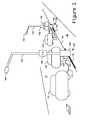
- FIG. 3shows a charging station using an electrolier streetlight
- FIG. 4shows a charging station using a utilitarian streetlight
- FIG. 5is an example schematic for a charging station monitoring a streetlight
- FIG. 6is an example schematic of a charging station monitoring combined streetlight and charging current
- FIG. 7is an example schematic of a charging station separately monitoring a streetlight and a charging current
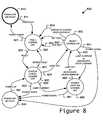
- FIG. 8is an example state transition diagram for controlling the operation of a charging station.
- sidewalk 20parallels street 10 , and is separated by curb 30 .
- Charging stations 100 of the present inventioncomprise streetlights 102 having light fixture 104 for illuminating street 10 .
- Cars 110 and 120are parked along street 10 , next to curb 30 , where cars 110 are electric vehicles, or hybrid vehicles, and are connected by charging cord 112 terminated by plug 114 to outlet 108 in base 106 of charging station 100 .
- Signage 130 , curb markings 132 , and in-street markers 134can designate streetlights 102 as being charging stations 100 , since outlet 108 might not be easily seen by a driver looking for a parking or charging location. Designations 130 , 132 , and 134 may be used individually, or in combination.
- Non-electric vehicles 120are preferably prohibited from parking in the locations designated by signage 130 or curb markings 132 while connectors 108 may be used for charging; however, if outlet 108 is not available for charging, for example when a lamp in light fixture 104 is lit causing streetlight 102 to use much of its electricity supply, then such a prohibition from parking may not apply.
- outlet 108may be replaced by another form of coupler to which electric vehicles may standardize.
- another cable(not shown) may be attached in place of outlet 108 and have its own connector (not shown) that is inserted into electric vehicle 110 for charging.
- the term “outlet”should be considered include to such alternative embodiments.
- FIG. 2a schematic of one prior art power supply 200 is shown to illustrate how power is supplied to streetlights 102 .
- most of power supply 200is located beneath street 10 and sidewalk 20 .
- power for streetlights 102may come from overhead wiring on power poles (described in conjunction with FIG. 4 below).
- the power mains 202are energized by a municipal supply (not shown) and may run for many miles. Periodically, for example every block, an electrical vault 204 is located below street 10 . Access is typically a manhole cover (not shown). Within vault 204 , power lines 206 are connect to mains 202 and run to one or both sides of the street 10 (only one side shown in FIG. 2 ), as needed to supply streetlights 102 . Power lines 206 comprise multiple conductors that carry, typically, two or three phase alternating current. Lines 206 pass through a conduit, under curb 30 , and into pull box 210 where main fuses 212 are located to limit the current draw of this interval of streetlights 102 .
- each streetlight pull box 220power is distributed under sidewalk 20 by power lines 214 to each streetlight pull box 220 , typically located in immediate proximity to corresponding streetlight 102 .
- streetlight fuse 222is provided to limit the current provided to streetlight 102 by power supply 200 .
- the last legis delivered by power lines 224 , which pass under sidewalk 20 , through conduit, into the base 106 (shown in FIG. 1 ) of streetlight 102 .
- control 240may comprise a starter and/or ballast or other circuit as needed to start and run lamp 242 .
- Control 240may further comprise a photoelectric sensor or a timer (neither shown) to turn on streetlight 102 as it gets dark and turn off as it gets light.
- Most municipalitiesrequire control 240 to fail-safe, so if something goes wrong with the sensor or timer of control 240 , corresponding streetlight 102 is on all of the time, rather than being off all of the time.
- FIG. 2The importance of FIG. 2 is not only to describe an example of power supply 200 and its protective elements, fuses 212 and 222 , but also to illustrate how much infrastructure, often below ground, is already in place to provide street lighting. Those skilled in the art already appreciate the difficulty of increasing the amount of power that supply 200 can deliver: All of cables 202 , 206 , 214 , and 224 may need to be replaced with larger gauges. The underground conduits carrying the present cables may be inadequate for larger conductors. Likewise, fuses 212 and 222 would need replacement.
- FIG. 3The conversion of streetlight 102 into charging station 100 of the present invention is shown.
- Power lines 224enter base 106 of streetlight 102 from beneath sidewalk 20 .
- charging station panel 330is a modification of or substitution for the cover panel for hand access port 230 .
- Internal wiring 234still runs up to light fixture 104 , containing control 240 and lamp 242 (shown in FIG. 2 ).
- Charging control module 332is preferably located inside of streetlight 102 when hand access port 230 is covered by charging station panel 330 , exposing only outlet 108 , reset switch 334 , and input 336 .
- Outlet 108connects with plug 114 of charging cable 112 of electric vehicle 110 for charging.
- Reset switch 334 and input 336when provided, are described below, in conjunction with FIGS. 5-8 .
- an integral ground-fault circuit interruptmay be provided (not shown), in which case ground-fault circuit interrupt functions need not be supplied by charging station 100 .
- FIG. 4An alternative embodiment of the present invention, shown in FIG. 4 , is charging station 400 , comprising utilitarian streetlight 402 mounted to power pole 401 .
- Streetlight 402has light fixture 104 which in the prior art would typically be connected directly to power supply lines 424 , but in the present invention is connected to charging control module 332 by lamp wiring 434 .
- Power supply lines 424should provide one or more phases of alternating current suitable for powering light fixture 104 , and should be protected by a fuse (not shown in FIG. 4 ).
- Power supply lines 424feeds charging control module 332 .
- Extension cable 438allows outlet 108 , reset switch 334 and input 336 to be located in box 430 at a convenient, accessible height.
- charging control module 332The details of one implementation of charging control module 332 are shown in FIG. 5 .
- Power supply lines 214are protected by fuse 222 and delivered to input terminals 510 by power lines 224 .
- Lighting circuit 501is completed by passing the power supply through charging control module 332 to output terminals 512 , to streetlight internal wiring 234 to control 240 , which in turn provides power to lamp 242 when lit.
- the power to control 240 and lamp 242 and their operationis unaffected by the insertion of charging control module 332 , which has merely elongated connection 232 by the insertion of terminals 510 and 512 and conductors 524 .
- Charging circuit 502comprises conductors 530 which tap into conductors 524 at or near input terminals 510 .
- Charging circuit 502further comprises, in series, a circuit breaker 532 to limit the current drawn through outlet 108 (i.e., by the vehicle 110 charging); a relay contact 534 (discussed below in conjunction with detector circuit 503 ); a ground-fault circuit interrupt 536 (if required); and, outlet 108 . While circuit breaker 532 , contact 534 , and ground-fault interrupt circuit 536 are closed, outlet 108 is available to charge vehicle 110 .
- ground-fault circuit interrupt 536may be omitted.
- Charger outlet 108may contain an interlock (not shown) whereby no electric potential is delivered to the contacts of outlet 108 until plug 114 is seated.
- circuit breaker 532 or ground-fault circuit interrupt 536are tripped, they can be reset with switch 334 (not shown in FIG. 5 ).
- ground-fault circuit interrupt 536is provided with a test button (not shown) that simulates a current leak to ground, e.g., through a resistor (not shown).
- a test button(not shown) that simulates a current leak to ground, e.g., through a resistor (not shown).
- such a testmay be performed by an external tester (not shown) plugged into outlet 108 , which shunts a small amount of current to ground.
- circuit breaker 532must be of a lower current rating and/or faster break response time than fuse 222 so that a inadvertent draw of excess current through charging circuit 502 trips breaker 532 (which can be reset by the operator of vehicle 110 ) rather than blowing fuse 222 , which requires a maintenance service call.
- Control circuit 503comprises detector 540 for detecting current flow in lighting circuit 501 and a driver 542 for operating relay 543 when the current in circuit 501 indicates that lamp 242 is lighting or lit.
- control circuit 503must be sufficiently fast that the steady state maximum draw on charging circuit 502 plus any in-rush current as control 240 begins to light lamp 242 does not damage fuse 222 before contact 534 opens circuit 502 .
- Response time under 100 mSshould be adequate in most cases, with response time of one-half cycle of the alternating current being preferred.
- relay 543comprising coil 544 and contact 534 may be an electromechanical device, or an analogous solid-state device (an example of which is Model A2425 manufactured by Crydom, Inc. of San Diego, Calif.).
- Contact 534 of relay 543may be normally-open, with coil 543 energized when the current sensed by detector 540 indicates lamp 242 is not lit.
- contact 534may be normally-closed, with coil 543 energized when detector 540 indicates lamp 242 is lit or lighting.
- breaker 534could have a shunt-trip input such that the contacts of breaker 532 would also serve as contact 534 and let coil 544 be the shunt-trip mechanism internal to the breaker (an example of such a device is the ED21B015 circuit breaker with the S01ED60 shunt trip accessory manufactured by Siemens Energy & Automation Inc. of Alpharetta, Ga.).
- relay 543may be a latching device which can be opened or closed by a corresponding pulse from driver 542 . Following the pulse, relay 543 would remain in the same state (opened or closed) until commanded to switch.
- Detector 540may be an inductive coil (as shown), a hall effect device, or may require a sense resistor or current shunt inline with conductor 524 across which a voltage drop is developed to which driver 542 responds.
- Driver 542requires a power source (not shown), which may be tapped from input terminals 510 , or developed inductively by detector 540 when current is flowing in conductors 524 .
- a battery and/or a solar-powered photovoltaicmay be used.
- An example of a suitable, integrated detector 540 , driver 542 , and relay 543is the AS3-NCAC-FF-15 Current Operated Switch by NK Technologies of Campbell, Calif., which integrates an inductive pickup for both current detection and power collection, drive electronics, and solid state relay.
- a similar productis the ECSJ407SC by Eaton Corporation, Moon Township, Pa.
- control 240may directly signal driver 542 (interconnection not shown) when lamp 242 is lit or lighting.
- detector 540may be a photodetector that optically senses the strike and illumination from lamp 242 .
- FIG. 6Another embodiment of charging control module 332 is shown in FIG. 6 .
- This embodimentalso consists of lighting circuit 601 , charging circuit 602 , and control circuit 603 .
- control circuit 603responds to the sum of the currents drawn by lighting circuit 601 and charging circuit 602
- control circuit 503responds to just the status of lighting circuit 501 as determined by detector 540 .
- the power supplyis provided at input terminals 610 and passed by conductors 624 to output terminals 612 to the streetlight control 240 and lamp 242 , forming lighting circuit 601 .
- Charging circuit 602is powered by conductors 624 , but the pickoff conductor 630 is at or near output terminals 612 so that current detector 640 will read the sum of currents drawn by lighting circuit 601 and charging circuit 602 .
- the driver 642 shown in FIG. 6is an example of a more integrated control circuit 603 , where the ground-fault detection coil 636 , current detector 640 , and coil 644 of relay 643 implement the functions of control circuit 503 , but without separate ground fault circuit interrupt 536 and circuit breaker 532 .
- reset switch 334may be electrical, as shown, and cause driver 642 to close contact 634 , provided the current in conductor 624 is not already too high (i.e., using enough current that allowing a vehicle to charge would likely exceed the rating of fuse 222 ).
- reset switch 334may be mechanical (not shown), allowing manual, latching closure of contact 634 , again provided the current in conductor 624 is not already too high. Care should be taken that a mechanical reset switch 634 does not permit an operator to directly and continuously hold contact 634 closed, as this would override the control of driver 642 and could permit currents in conductor 624 to threaten fuse 222 .
- driver 642 responsive to the total of the currents drawn by lighting and charging circuits 601 and 602is desirable, since a retrofit of streetlight 102 in which lamp 242 is replaced with an LED-based illuminator (not shown) would likely reduce the current draw of circuit 601 well below the rating of fuse 222 , and this may be sufficient to allow simultaneous operation of lighting and charging circuits 601 and 602 .
- FIG. 7That same advantage can be obtained using another embodiment, shown in FIG. 7 in which the streetlight circuit 701 passes through charging control module 332 at input terminals 710 , through conductors 724 , and output terminals 712 .
- Conductor 730 of charging circuit 702taps off of conductors 724 near input terminals 710 .
- Charging circuit 702can be interrupted by contact 734 of relay 743 .
- charging control circuit 703uses current sensor 740 to monitor the current in lighting circuit 701 , while current sensor 746 is used to monitor the current in charging circuit 702 .
- Driver 742computes the total current drawn by lighting and charging circuits 701 and 702 (whether through an analog sum or through separate analog to digital conversions which are then summed). If the total current drawn is above a value determined to threaten fuse 222 , then coil 744 is appropriately driven to cause contact 734 to open.
- Ground-fault sensor 736may be monitored by driver 742 to interrupt circuit 702 with relay 743 when a ground-fault is detected.
- Switch 334may be an electrical or mechanical switch to reset contact 734 following an over-current or a ground-fault detection which resulted in contact 734 being opened.
- driver 742also comprises voltage monitor connection 748 .
- the instantaneous product of the measured voltage (e.g., in volts) at connection 748 and the current measured with current detector 746 (e.g., in amps)represents the instantaneous power drawn through circuit 702 (in watts).
- This instantaneous powerperiodically (e.g., 1000 times per second) and multiplying that reading by the period (i.e., 1 mS), and accumulating the result as the measure of energy transferred (i.e., watt-seconds, or with the appropriate conversion factors, kilowatt-hours).
- a similar measure of energy delivered to lighting circuit 701may also be made and recorded, if desired.
- a similar measurementcould be made with current detector 640 of charging control circuit 603 (which would, of course, require the additional of a voltage measurement connection like 748 , not shown in FIG. 6 ), so that a power measurement would represent the total power being delivered to both lighting circuit 601 and charging circuit 602 .
- FIG. 7also shows monitoring and communication subsystem 750 , which also may be connected to charge control circuit 503 , 603 .
- Monitoring and communication subsystem 750preferably comprises a control 752 having access to memory 754 for storing the software program of control 752 .
- Memory 754may also store data, for example, data representative of the accumulated power (i.e., energy, as in watt-hours) delivered through charger circuit 702 as measured and communicated by driver 742 to control 752 .
- Such record of energy deliveredis preferably stored in non-volatile memory. (Note that while this is a preferred implementation for an energy meter, other implementations are well known.)
- Memory 754may also contain a unique identifier for identifying charging control module 332 , and by association, streetlight 102 , which is useful for reporting and management.
- a unique identifiermay be provided in control 752 (e.g., a unique CPU serial number) or in communications module 756 (e.g., a Media Access Control address, or MAC address).
- Monitoring and communication subsystem 750may comprise a human readable display (not shown) and/or a short range wireless reporting system (not shown) such as those commonly used for utility meter reading to allow efficient readout of the record of energy delivered and the unique identifier of the charge control module 332 .
- monitoring and communication subsystem 750further comprises communication module 756 which is able to connect through communication channel 762 with management server 760 located at a remote site, for status monitoring, meter reading, and billing (discussed below in conjunction with input 336 ).
- Communication channel 762preferably comprises a wireless leg and may further comprise other communications legs, including the Internet.
- the wireless leg(s)may be based on any of a number of wireless network technologies, for example, cellular telephone, IEEE 802.11 (i.e., WiFi), or IEEE 802.15.4 (i.e., ZigBee). In some wireless network topologies, for example those using ZigBee, communications from charging control module 332 in one streetlight 102 may be routed and relayed through other such modules 332 in other streetlights 102 until a gateway is reached.
- Management server 760may receive reports from charging control modules 332 , or may interrogate them, or both. Whether communication is initiated by management server 760 , or by communication module 756 , management server 760 is able to access status, energy meter records, and other information.
- Monitoring and communication subsystem 750preferably comprises input 336 , which accepts an authorization code (which may be an identification) supplied by a user before enabling charging circuit 702 and outlet 108 .
- input 336is an RFID (radio-frequency identification) reader that is able to read authorization token 770 , comprising an RFID tag.
- authorization token 770may be a magnetic card (for instance, a credit card or drivers license) and input 336 comprises a magnetic card reader, in which case the authentication code comprises the credit card number or drivers license number contained on the magnetic stripe of the card).
- input 336may comprise a keyboard and a user enters an authentication code (i.e., an identification number, personal identification number, or passcode) manually, rather than using a token that is read.
- an RFID tag or other authorization token, identification code, or passcodewould be provided to the authorized users in advance.
- the authorization codewould be accepted by input 336 .
- the authorization code so receivedis used by control 752 to query management server 760 (through communication channel 762 ) to verify the authorization code. If server 760 responds that the authorization code represents a currently authorized user, then the user is validated and charging circuit 702 may be energized.
- management server 760may accumulate the monthly usage by each user and bill periodically (e.g., adding the energy consumed from each of a user's chargings to the user's utility bill, and in the case of an electric vehicle with a utility-interactive inverter, crediting a user for energy supplied by the vehicle), or may handle each transaction independently (e.g., placing a charge or credit to the credit card used as authorization token 770 ).
- a simple example use casewould be that, during daylight hours, while the streetlights 102 are not lit, a user (not shown) pulls up to streetlight 102 in electric vehicle 110 and parks.
- Userconnects vehicle 110 to charging station 100 by plugging charging cable 112 into charging outlet 108 .
- userpresses reset switch 334 to clear a previous ground-fault circuit interrupt or current overload condition.
- the userpresents an authorization code through input 336 , for example by passing a key fob containing an RFID authorization token 770 in proximity to input 336 .
- Charging circuit 502 , 602 , or 702is active, and electric vehicle 110 is charging.
- streetlight control 240begins to light lamp 242 .
- the increased current drawn by lighting circuit 501 , 601 , or 701is detected, and relay 543 , 643 , or 743 actuates to open lighting circuit 502 , 602 , or 702 , all respectively, without threatening fuse 222 .
- FIGS. 5-7have shown a single-phase power supply to facilitate explanation, the principles presented here can be adapted for a two- or three-phase power system to provide more power and correspondingly shorter vehicle charge times.
- a state transition diagram 800 for the charging station 100 of the present inventionis shown in FIG. 8 .
- Unpowered, faulted state 810is the initial state, occurring when charging control module 332 is unpowered with a fault recorded.
- module 332is delivered from the factory in this state. The only transition from this state occurs when power is applied 811 , where module 332 transitions to a faulted state 820 .
- faulted state 820charging circuit 502 , 602 , 702 is off. If power is removed 821 while in faulted state 820 , the module 332 transitions back to unpowered, faulted state 810 . If reset switch 334 is thrown 822 , module 332 transitions to check state 830 .
- check state 830charging circuit 502 , 602 , 702 remains off.
- driver 542first tests for a wiring fault (e.g., a reversal of hot and neutral lines feeding the charging circuit) and if detected 831 , module 332 transitions back to faulted state 820 . This prevents module 332 from operating while miswired. Otherwise, if power is removed 832 (or fails), module 332 transitions to unpowered, unfaulted state 840 .
- a wiring faulte.g., a reversal of hot and neutral lines feeding the charging circuit
- module 332transitions to lamp on state 860 . Otherwise, lamp 242 is considered off 834 , and module 332 transitions to ready state 850 .
- unpowered, unfaulted state 840the only transition is when power is reapplied 841 , to check state 830 .
- unpowered, unfaulted state 840may be folded together with unpowered, faulted state 810 , and when power is restored, the successor state is faulted state 820 .
- charging circuit 502 , 602 , 702is enabled, unless required by policy to be enabled by an authorization or activation through input 334 (not explicitly shown in state transition diagram 800 ). If power is removed 851 , the system transitions to unpowered, unfaulted state 840 . If a ground-fault is detected 852 , or a ground-fault is induced by test 853 , the state transitions to faulted state 820 , and charging circuit 502 , 602 , 702 is disabled.
- charging circuit 502 , 602 , 702 current drawexceeds a predetermined value 854 , a value selected to protect fuse 222 , then the system transitions to faulted state 820 : In the case of example charging circuit 502 , this would correspond to tripping the circuit breaker 532 , whereas in example charging circuit 602 , 702 , the corresponding driver 642 , 742 would open the corresponding relay 643 , 743 .
- charging circuit 502 , 602 , 702Upon entry into lamp on state 860 , charging circuit 502 , 602 , 702 is disabled, and the streetlight 102 operates normally. Note that charging control module 332 , as shown, does not protect fuse 222 from excessive currents drawn solely by lighting circuit 501 , 601 , 701 . From lamp on state 860 , if power is removed 861 , the state transitions to unpowered, unfaulted state 840 . When the current in lighting circuit 501 , 601 , 701 is detected as being below a predetermined value 862 indicating that lamp 242 is no longer lit, charging control module 332 transitions to ready state 850 .
- the predetermined value that indicates that lamp 242 is no longer litis different than the predetermined value indicative of lamp 242 lighting used to trigger transition 855 , as some degree of hysteresis is desirable to prevent unwanted, rapid oscillations between ready state 850 and lamp on state 860 .
- a time delay of several seconds or minutesmay further be included in conjunction with transition 862 during which a re-lighting of lamp 242 would cause the system to return to lamp on state 860 without having energized charging circuit 502 , 602 , 702 .
- Embodiments of the present inventionshould comply with Article 625 of the National Electrical Code, and if used to support an electric vehicle feeding energy back into the electric grid, then embodiments should further comply with Article 705.
Landscapes
- Engineering & Computer Science (AREA)
- Power Engineering (AREA)
- Transportation (AREA)
- Mechanical Engineering (AREA)
- Life Sciences & Earth Sciences (AREA)
- Sustainable Development (AREA)
- Sustainable Energy (AREA)
- Charge And Discharge Circuits For Batteries Or The Like (AREA)
Abstract
Description
Claims (20)
Priority Applications (2)
| Application Number | Priority Date | Filing Date | Title |
|---|---|---|---|
| US12/387,877US8111043B2 (en) | 2009-05-08 | 2009-05-08 | Method and apparatus for charging an electric vehicle from a streetlight |
| US13/352,354US8749199B2 (en) | 2009-05-08 | 2012-01-18 | Method and apparatus for charging an electric vehicle from a streetlight |
Applications Claiming Priority (1)
| Application Number | Priority Date | Filing Date | Title |
|---|---|---|---|
| US12/387,877US8111043B2 (en) | 2009-05-08 | 2009-05-08 | Method and apparatus for charging an electric vehicle from a streetlight |
Related Child Applications (1)
| Application Number | Title | Priority Date | Filing Date |
|---|---|---|---|
| US13/352,354Continuation-In-PartUS8749199B2 (en) | 2009-05-08 | 2012-01-18 | Method and apparatus for charging an electric vehicle from a streetlight |
Publications (2)
| Publication Number | Publication Date |
|---|---|
| US20100283426A1 US20100283426A1 (en) | 2010-11-11 |
| US8111043B2true US8111043B2 (en) | 2012-02-07 |
Family
ID=43061951
Family Applications (1)
| Application Number | Title | Priority Date | Filing Date |
|---|---|---|---|
| US12/387,877Expired - Fee RelatedUS8111043B2 (en) | 2009-05-08 | 2009-05-08 | Method and apparatus for charging an electric vehicle from a streetlight |
Country Status (1)
| Country | Link |
|---|---|
| US (1) | US8111043B2 (en) |
Cited By (20)
| Publication number | Priority date | Publication date | Assignee | Title |
|---|---|---|---|---|
| US20100320018A1 (en)* | 2009-06-18 | 2010-12-23 | Ford Global Technologies, Llc | Method And System To Prevent Vehicle Driveaway During Battery Charging |
| US20110029146A1 (en)* | 2009-07-28 | 2011-02-03 | Michael Muller | Plug-In Electric Vehicle Supply Equipment |
| US20110130885A1 (en)* | 2009-12-01 | 2011-06-02 | Bowen Donald J | Method and system for managing the provisioning of energy to or from a mobile energy storage device |
| US20110144823A1 (en)* | 2009-07-28 | 2011-06-16 | Michael Muller | Sequential Charging of Multiple Electric Vehicles |
| US20110285345A1 (en)* | 2010-05-19 | 2011-11-24 | Hitachi, Ltd. | Method of receiving charge, method of controlling charge, charge control unit and charging equipment |
| US20120229085A1 (en)* | 2011-03-07 | 2012-09-13 | Lau David M K | System for charging electric vehicle batteries from street lights and parking meters |
| US20130015806A1 (en)* | 2011-07-13 | 2013-01-17 | Lumenir, Inc. | Tamper-Resistant Network-Attached Energy System with Access Control |
| US20130309022A1 (en)* | 2011-01-28 | 2013-11-21 | Unimi Solutions Ab | Foundation system for charging poles |
| US20140002018A1 (en)* | 2012-06-29 | 2014-01-02 | Schneider Electric USA, Inc. | Coupler For Electric Vehicle Charging Station |
| US8624719B2 (en) | 2011-06-03 | 2014-01-07 | Bosch Automotive Service Solutions Llc | Smart phone control and notification for an electric vehicle charging station |
| US8725330B2 (en) | 2010-06-02 | 2014-05-13 | Bryan Marc Failing | Increasing vehicle security |
| US8929069B2 (en) | 2012-05-31 | 2015-01-06 | Bosch Automotive Service Solutions Llc | Electric vehicle charging system with robustness features and universal port |
| US20150077239A1 (en)* | 2011-12-16 | 2015-03-19 | Aerovironment, Inc. | Electric Vehicle Charger Display System for Distant and Local Viewing |
| US9013206B2 (en) | 2012-05-31 | 2015-04-21 | Bosch Automotive Service Solutions Inc. | Plug-in electric vehicle supply equipment having a process and device for circuit testing |
| US9054539B2 (en) | 2012-05-31 | 2015-06-09 | Bosch Automotive Service Solutions Inc. | Arrangement and process for housing electric vehicle supply equipment |
| US9121073B2 (en) | 2009-07-28 | 2015-09-01 | Bosch Automotive Service Solutions Inc. | Plug-in electric vehicle supply equipment with indicators |
| US9348381B2 (en) | 2011-10-19 | 2016-05-24 | Zeco Systems Pte Ltd | Methods and apparatuses for charging of electric vehicles |
| US9561731B2 (en) | 2011-12-13 | 2017-02-07 | Brightfield Transportation Solutions, Inc. | Structural bollard assembly for electric vehicle infrastructure |
| US20180056799A1 (en)* | 2016-08-23 | 2018-03-01 | GM Global Technology Operations LLC | Hands-free conductive battery charger for an electric vehicle |
| US20230256845A1 (en)* | 2022-02-16 | 2023-08-17 | The StressCrete Group | Fully enclosed secure ev charging system |
Families Citing this family (35)
| Publication number | Priority date | Publication date | Assignee | Title |
|---|---|---|---|---|
| US7906937B2 (en)* | 2009-06-02 | 2011-03-15 | Coulomb Technologies, Inc. | Overcurrent and ground fault protection in a networked charging station for electric vehicles |
| US9434268B2 (en)* | 2009-08-11 | 2016-09-06 | Siemens Industry, Inc. | Electrical distribution system recharging station for electric vehicles |
| US20110084659A1 (en)* | 2009-10-08 | 2011-04-14 | Power*Otg Incorporated | Mobile cart docking and communication system |
| US8232765B2 (en) | 2010-03-13 | 2012-07-31 | James A Billmaier | Automatic and dynamic home electricity load balancing for the purpose of EV charging |
| DE102010012366B4 (en)* | 2010-03-22 | 2013-04-04 | Patrick Wolfien | Parking Management System |
| FR2958091B1 (en)* | 2010-03-23 | 2012-06-01 | Citelum | METHOD FOR CONTROLLING POWER SUPPLY FROM A PUBLIC NETWORK ASSIGNED TO LIGHTING THE PUBLIC ROAD |
| US7986126B1 (en) | 2010-10-01 | 2011-07-26 | Toyota Motor Sales, U.S.A., Inc. | Automated system for determining whether vehicle charge station is publicly accessible |
| WO2012090229A2 (en)* | 2010-12-31 | 2012-07-05 | Logica Private Limited | Driver authentication and vehicle data communication apparatus |
| US8970438B2 (en)* | 2011-02-11 | 2015-03-03 | Telefonaktiebolaget L M Ericsson (Publ) | Method of providing an antenna mast and an antenna mast system |
| WO2012142695A1 (en)* | 2011-04-15 | 2012-10-26 | Thomas Patrick Bryson | Lamp post with power receptacle for electric vehicle charging |
| WO2012160481A2 (en)* | 2011-05-24 | 2012-11-29 | Koninklijke Philips Electronics N.V. | A charging module, a server, and a charging system comprising the charging module and the server |
| WO2013020575A1 (en)* | 2011-08-05 | 2013-02-14 | Abb Research Ltd | An electronic protection device for an electric vehicle charging device. |
| US8810198B2 (en)* | 2011-09-02 | 2014-08-19 | Tesla Motors, Inc. | Multiport vehicle DC charging system with variable power distribution according to power distribution rules |
| GB201115322D0 (en) | 2011-09-06 | 2011-10-19 | Electric Car Charging Company Ltd | An improved lamp column |
| US9368959B2 (en) | 2011-09-06 | 2016-06-14 | Robert W. Wright, JR. | Displacement safety system for electrical charging stations |
| WO2013043904A2 (en) | 2011-09-21 | 2013-03-28 | Jeff Thramann | Electric Vehicle Charging Station Adapted for the Delivery of Goods and Services |
| CN103123732B (en)* | 2011-11-21 | 2016-08-10 | 鸿富锦精密工业(深圳)有限公司 | A kind of public charging management system and charging method |
| US9760875B2 (en)* | 2012-04-05 | 2017-09-12 | Menolinx System Ltd. | Device and method for automatic billing of power consumption through street poles |
| DE102012022963A1 (en)* | 2012-11-19 | 2014-05-22 | Ebee Smart Technologies Gmbh | Charging station for charging an electrical consumer and method |
| EP2920023B1 (en)* | 2012-11-19 | 2019-11-06 | Liros Power Solution AB | Electrical vehicle batterry charger mounted on lamp post |
| FR3008237B1 (en)* | 2013-07-08 | 2017-04-14 | Inesocompany Ltd | METHOD AND SYSTEM FOR BATTERY CHARGING |
| US9168835B2 (en)* | 2013-11-27 | 2015-10-27 | GM Global Technology Operations LLC | Systems and methods for auxiliary power outlet control |
| CN106611460A (en)* | 2015-10-22 | 2017-05-03 | 熊小宁 | A sinking type self-service fee paying charging pole |
| DE102016225134A1 (en) | 2016-12-15 | 2018-06-21 | Audi Ag | Charging arrangement for supplying an electrical consumer and system |
| US11440420B2 (en)* | 2017-06-28 | 2022-09-13 | Trojan Energy Limited | Apparatus and system for connecting electric vehicles to an electrical network and method of use |
| EP3424800B1 (en)* | 2017-07-03 | 2020-09-09 | Volvo Car Corporation | Method and system for automatic parking of a vehicle |
| GB2569786A (en)* | 2017-12-20 | 2019-07-03 | Connected Kerb Ltd | Kerbside vehicle charger |
| FR3076260B1 (en)* | 2017-12-29 | 2021-07-23 | Mft Dappareillage Electrique De Cahors | MULTI-PURPOSE TERMINAL FOR CHARGING ELECTRIC VEHICLES AND PROCESS FOR MANAGING THE SAID TERMINAL |
| GB2583982B (en) | 2019-09-03 | 2021-11-03 | Hector Macdonald Benjamin | Cable support |
| US11937082B1 (en) | 2019-12-03 | 2024-03-19 | Eve Energy Ventures Inc. | Secure electric vehicle charger and system incorporating thereof |
| US11413977B2 (en)* | 2020-12-11 | 2022-08-16 | Dovene Komi Deh | Charging assembly for electric vehicle |
| JP7552509B2 (en)* | 2021-06-08 | 2024-09-18 | トヨタ自動車株式会社 | Server and power supply system |
| US20230115083A1 (en)* | 2021-10-13 | 2023-04-13 | Fermata Energy Llc | Methods of using bidirectional charging to supply back-up power and increase resiliency of powered networks |
| US20240075833A1 (en)* | 2022-05-04 | 2024-03-07 | Harrison Metals, Inc. | Utility Pole Mounted Charging Station |
| MA60000B1 (en)* | 2023-04-06 | 2025-01-31 | Mascir (Moroccan Foundation For Advanced Science, Innovation & Research) | Universal fast charging station for electric scooter batteries |
Citations (2)
| Publication number | Priority date | Publication date | Assignee | Title |
|---|---|---|---|---|
| US20090177580A1 (en)* | 2008-01-07 | 2009-07-09 | Lowenthal Richard W | Collection of electric vehicle power consumption tax |
| US20100013434A1 (en)* | 2006-06-08 | 2010-01-21 | Elektromotive Ltd. | Charging station |
- 2009
- 2009-05-08USUS12/387,877patent/US8111043B2/ennot_activeExpired - Fee Related
Patent Citations (2)
| Publication number | Priority date | Publication date | Assignee | Title |
|---|---|---|---|---|
| US20100013434A1 (en)* | 2006-06-08 | 2010-01-21 | Elektromotive Ltd. | Charging station |
| US20090177580A1 (en)* | 2008-01-07 | 2009-07-09 | Lowenthal Richard W | Collection of electric vehicle power consumption tax |
Cited By (53)
| Publication number | Priority date | Publication date | Assignee | Title |
|---|---|---|---|---|
| US8393423B2 (en)* | 2009-06-18 | 2013-03-12 | Ford Global Technologies, Llc | Method and system to prevent vehicle driveaway during battery charging |
| US8863870B2 (en)* | 2009-06-18 | 2014-10-21 | Ford Global Technologies, Llc | Method and system to prevent vehicle driveaway during battery charging |
| US20100320018A1 (en)* | 2009-06-18 | 2010-12-23 | Ford Global Technologies, Llc | Method And System To Prevent Vehicle Driveaway During Battery Charging |
| US20130123064A1 (en)* | 2009-06-18 | 2013-05-16 | Ford Global Technologies, Llc | Method And System To Prevent Vehicle Driveaway During Battery Charging |
| US9121073B2 (en) | 2009-07-28 | 2015-09-01 | Bosch Automotive Service Solutions Inc. | Plug-in electric vehicle supply equipment with indicators |
| US20110144823A1 (en)* | 2009-07-28 | 2011-06-16 | Michael Muller | Sequential Charging of Multiple Electric Vehicles |
| US8860366B2 (en) | 2009-07-28 | 2014-10-14 | Bosch Automotive Service Solutions Llc | Plug-in electric vehicle supply equipment |
| US9487099B2 (en) | 2009-07-28 | 2016-11-08 | Bosch Automotive Service Solutions Inc. | Plug-in electric vehicle supply equipment |
| US8890473B2 (en) | 2009-07-28 | 2014-11-18 | Bosch Automotive Service Solutions Llc | Sequential charging of multiple electric vehicles |
| US20110029146A1 (en)* | 2009-07-28 | 2011-02-03 | Michael Muller | Plug-In Electric Vehicle Supply Equipment |
| US20110130885A1 (en)* | 2009-12-01 | 2011-06-02 | Bowen Donald J | Method and system for managing the provisioning of energy to or from a mobile energy storage device |
| US20150326040A1 (en)* | 2010-05-19 | 2015-11-12 | Hitachi, Ltd. | Method of receiving charge, method of controlling charge, charge control unit and charging equipment |
| US9168841B2 (en)* | 2010-05-19 | 2015-10-27 | Hitachi, Ltd. | Method of receiving charge, method of controlling charge, charge control unit and charging equipment |
| US20110285345A1 (en)* | 2010-05-19 | 2011-11-24 | Hitachi, Ltd. | Method of receiving charge, method of controlling charge, charge control unit and charging equipment |
| US8725330B2 (en) | 2010-06-02 | 2014-05-13 | Bryan Marc Failing | Increasing vehicle security |
| US8841881B2 (en) | 2010-06-02 | 2014-09-23 | Bryan Marc Failing | Energy transfer with vehicles |
| US10124691B1 (en) | 2010-06-02 | 2018-11-13 | Bryan Marc Failing | Energy transfer with vehicles |
| US11186192B1 (en) | 2010-06-02 | 2021-11-30 | Bryan Marc Failing | Improving energy transfer with vehicles |
| US9393878B1 (en) | 2010-06-02 | 2016-07-19 | Bryan Marc Failing | Energy transfer with vehicles |
| US9114719B1 (en) | 2010-06-02 | 2015-08-25 | Bryan Marc Failing | Increasing vehicle security |
| US9376831B2 (en)* | 2011-01-28 | 2016-06-28 | Unimi Solutions Ab | Foundation system for charging poles |
| US20130309022A1 (en)* | 2011-01-28 | 2013-11-21 | Unimi Solutions Ab | Foundation system for charging poles |
| US20120229085A1 (en)* | 2011-03-07 | 2012-09-13 | Lau David M K | System for charging electric vehicle batteries from street lights and parking meters |
| US8624719B2 (en) | 2011-06-03 | 2014-01-07 | Bosch Automotive Service Solutions Llc | Smart phone control and notification for an electric vehicle charging station |
| US20130015806A1 (en)* | 2011-07-13 | 2013-01-17 | Lumenir, Inc. | Tamper-Resistant Network-Attached Energy System with Access Control |
| US9348381B2 (en) | 2011-10-19 | 2016-05-24 | Zeco Systems Pte Ltd | Methods and apparatuses for charging of electric vehicles |
| US10192245B2 (en) | 2011-10-19 | 2019-01-29 | Zeco Systems Pte Ltd. | Methods and apparatuses for charging of electric vehicles |
| US11756087B2 (en) | 2011-10-19 | 2023-09-12 | Zeco Systems Pte Ltd. | Systems and methods for charging of electric vehicles with charge balancing between multiple electric vehicle charging stations |
| US11715136B2 (en) | 2011-10-19 | 2023-08-01 | Zeco Systems Pte Ltd. | Methods and apparatuses for charging of electric vehicles |
| US11715138B2 (en) | 2011-10-19 | 2023-08-01 | Zeco Systems Pte Ltd. | Methods and systems for charging of electric vehicles |
| US11756086B2 (en) | 2011-10-19 | 2023-09-12 | Zeco Systems Pte Ltd. | Methods and systems for charging of electric vehicles |
| US12190360B2 (en) | 2011-10-19 | 2025-01-07 | Zeco Systems Pte Ltd. | Systems and methods for charging of electric vehicles with charge balancing between multiple electric vehicle charging stations in a microgrid |
| US10872361B2 (en) | 2011-10-19 | 2020-12-22 | Zeco Systems Pte Ltd. | Methods and apparatuses for charging of electric vehicles |
| US10169783B2 (en) | 2011-10-19 | 2019-01-01 | Zeco Systems Pte Ltd. | Methods and apparatuses for charging of electric vehicles |
| US10185978B2 (en) | 2011-10-19 | 2019-01-22 | Zeco Systems Pte Ltd. | Methods and apparatuses for charging of electric vehicles |
| US10185977B2 (en) | 2011-10-19 | 2019-01-22 | Zeco Systems Pte Ltd. | Methods and apparatuses for charging of electric vehicles |
| US11748788B2 (en) | 2011-10-19 | 2023-09-05 | Zeco Systems Pte Ltd. | Methods and systems for determining the availability of an electric vehicle charging station |
| US10210552B2 (en) | 2011-10-19 | 2019-02-19 | Zeco Systems Pte Ltd. | Methods and apparatuses for charging of electric vehicles |
| US12175506B2 (en) | 2011-10-19 | 2024-12-24 | Zeco Systems Pte Ltd. | Systems and methods for charging of electric vehicles with charge balancing between multiple electric vehicle charging stations in a local area network |
| US10586258B2 (en) | 2011-10-19 | 2020-03-10 | Zeco Systems Pte Ltd. | Methods and apparatuses for charging of electric vehicles |
| US10839433B2 (en) | 2011-10-19 | 2020-11-17 | Zeco Systems Pte Ltd. | Methods and apparatuses for charging of electric vehicles |
| US10846763B2 (en) | 2011-10-19 | 2020-11-24 | Zeco Systems Ptd Ltd. | Methods and apparatuses for charging of electric vehicles |
| US10861066B2 (en) | 2011-10-19 | 2020-12-08 | Zeco Systems Pte Ltd. | Methods and apparatuses for charging of electric vehicles |
| US9561731B2 (en) | 2011-12-13 | 2017-02-07 | Brightfield Transportation Solutions, Inc. | Structural bollard assembly for electric vehicle infrastructure |
| US20150077239A1 (en)* | 2011-12-16 | 2015-03-19 | Aerovironment, Inc. | Electric Vehicle Charger Display System for Distant and Local Viewing |
| US8929069B2 (en) | 2012-05-31 | 2015-01-06 | Bosch Automotive Service Solutions Llc | Electric vehicle charging system with robustness features and universal port |
| US9013206B2 (en) | 2012-05-31 | 2015-04-21 | Bosch Automotive Service Solutions Inc. | Plug-in electric vehicle supply equipment having a process and device for circuit testing |
| US9054539B2 (en) | 2012-05-31 | 2015-06-09 | Bosch Automotive Service Solutions Inc. | Arrangement and process for housing electric vehicle supply equipment |
| US20140002018A1 (en)* | 2012-06-29 | 2014-01-02 | Schneider Electric USA, Inc. | Coupler For Electric Vehicle Charging Station |
| US9352652B2 (en)* | 2012-06-29 | 2016-05-31 | Schneider Electric USA, Inc. | Coupler for electric vehicle charging station |
| US10286799B2 (en)* | 2016-08-23 | 2019-05-14 | GM Global Technology Operations LLC | Hands-free conductive battery charger for an electric vehicle |
| US20180056799A1 (en)* | 2016-08-23 | 2018-03-01 | GM Global Technology Operations LLC | Hands-free conductive battery charger for an electric vehicle |
| US20230256845A1 (en)* | 2022-02-16 | 2023-08-17 | The StressCrete Group | Fully enclosed secure ev charging system |
Also Published As
| Publication number | Publication date |
|---|---|
| US20100283426A1 (en) | 2010-11-11 |
Similar Documents
| Publication | Publication Date | Title |
|---|---|---|
| US8111043B2 (en) | Method and apparatus for charging an electric vehicle from a streetlight | |
| US8749199B2 (en) | Method and apparatus for charging an electric vehicle from a streetlight | |
| US12227083B2 (en) | Annunciating or power vending circuit breaker for an electric load | |
| CN1060596C (en) | Electricity distribution network and method and device for controlling output current from the electric distribution network | |
| US20120286729A1 (en) | Electric vehicle supply equipment with over-current protection | |
| US20100198751A1 (en) | Plug-in hybrid recharge power system | |
| CA2809137C (en) | Controlling power supply to vehicles through a series of electrical outlets | |
| Somefun et al. | Smart prepaid energy metering system to detect energy theft with facility for real time monitoring | |
| EP2810816A2 (en) | System and method for charging electric vehicles | |
| JP2010166794A (en) | Charging stand system, charging method, and charging service providing method | |
| CN103311984A (en) | Alternating current charging post for electric automobile | |
| US8355832B2 (en) | Controlling power supply to vehicles through a series of electrical outlets | |
| KR20110106201A (en) | Intelligent energy supply / management system | |
| KR20120131452A (en) | A Remote Power Switching System Of A Power Provider For Detecting Earth Leakage & Remote Power Switching of the Provider | |
| CN208469586U (en) | A kind of electric car intelligent sharing AC charging system | |
| WO2009021324A1 (en) | Controlling power supply to vehicles through a series of electrical outlets | |
| CN110481354A (en) | Power supply system and its method of supplying power to based on electric pole charging unit | |
| Turner | Charging forward: An EVSE buyers guide | |
| US20240181905A1 (en) | Apparatus and system for connecting electric vehicles to an electrical network and method of use | |
| CA3035630A1 (en) | Charging station, electric vehicle and system comprising a charging station and an electric vehicle | |
| Williams | Getting it right: Choosing home EV charging for your customers | |
| FI12994Y1 (en) | Apparatus for charging electric vehicles and for managing and controlling the other electrical load of a building |
Legal Events
| Date | Code | Title | Description |
|---|---|---|---|
| ZAAA | Notice of allowance and fees due | Free format text:ORIGINAL CODE: NOA | |
| ZAAB | Notice of allowance mailed | Free format text:ORIGINAL CODE: MN/=. | |
| REMI | Maintenance fee reminder mailed | ||
| FEPP | Fee payment procedure | Free format text:PETITION RELATED TO MAINTENANCE FEES GRANTED (ORIGINAL EVENT CODE: PMFG); ENTITY STATUS OF PATENT OWNER: SMALL ENTITY Free format text:PETITION RELATED TO MAINTENANCE FEES FILED (ORIGINAL EVENT CODE: PMFP); ENTITY STATUS OF PATENT OWNER: SMALL ENTITY | |
| LAPS | Lapse for failure to pay maintenance fees | ||
| REIN | Reinstatement after maintenance fee payment confirmed | ||
| PRDP | Patent reinstated due to the acceptance of a late maintenance fee | Effective date:20160315 | |
| FPAY | Fee payment | Year of fee payment:4 | |
| STCF | Information on status: patent grant | Free format text:PATENTED CASE | |
| SULP | Surcharge for late payment | ||
| AS | Assignment | Owner name:LIBERTY PLUGINS LLC, CALIFORNIA Free format text:ASSIGNMENT OF ASSIGNORS INTEREST;ASSIGNOR:REDMANN, WILLIAM GIBBENS;REEL/FRAME:038019/0144 Effective date:20160317 | |
| FP | Lapsed due to failure to pay maintenance fee | Effective date:20160207 | |
| AS | Assignment | Owner name:LIBERTY PLUGINS, INC., CALIFORNIA Free format text:CORRECTIVE ASSIGNMENT TO CORRECT THE ASSIGNEE NAME PREVIOUSLY RECORDED AT REEL: 038019 FRAME: 0144. ASSIGNOR(S) HEREBY CONFIRMS THE ASSIGNMENT;ASSIGNOR:REDMANN, WILLIAM GIBBENS;REEL/FRAME:046173/0234 Effective date:20160317 | |
| FEPP | Fee payment procedure | Free format text:MAINTENANCE FEE REMINDER MAILED (ORIGINAL EVENT CODE: REM.); ENTITY STATUS OF PATENT OWNER: SMALL ENTITY | |
| FEPP | Fee payment procedure | Free format text:7.5 YR SURCHARGE - LATE PMT W/IN 6 MO, SMALL ENTITY (ORIGINAL EVENT CODE: M2555); ENTITY STATUS OF PATENT OWNER: SMALL ENTITY | |
| MAFP | Maintenance fee payment | Free format text:PAYMENT OF MAINTENANCE FEE, 8TH YR, SMALL ENTITY (ORIGINAL EVENT CODE: M2552); ENTITY STATUS OF PATENT OWNER: SMALL ENTITY Year of fee payment:8 | |
| FEPP | Fee payment procedure | Free format text:MAINTENANCE FEE REMINDER MAILED (ORIGINAL EVENT CODE: REM.); ENTITY STATUS OF PATENT OWNER: SMALL ENTITY | |
| LAPS | Lapse for failure to pay maintenance fees | Free format text:PATENT EXPIRED FOR FAILURE TO PAY MAINTENANCE FEES (ORIGINAL EVENT CODE: EXP.); ENTITY STATUS OF PATENT OWNER: SMALL ENTITY | |
| STCH | Information on status: patent discontinuation | Free format text:PATENT EXPIRED DUE TO NONPAYMENT OF MAINTENANCE FEES UNDER 37 CFR 1.362 | |
| FP | Lapsed due to failure to pay maintenance fee | Effective date:20240207 |