US8110744B2 - Flexible shielded cable - Google Patents
Flexible shielded cableDownload PDFInfo
- Publication number
- US8110744B2 US8110744B2US12/193,850US19385008AUS8110744B2US 8110744 B2US8110744 B2US 8110744B2US 19385008 AUS19385008 AUS 19385008AUS 8110744 B2US8110744 B2US 8110744B2
- Authority
- US
- United States
- Prior art keywords
- conductors
- unshielded
- conductor
- flexibility
- flexible cable
- Prior art date
- Legal status (The legal status is an assumption and is not a legal conclusion. Google has not performed a legal analysis and makes no representation as to the accuracy of the status listed.)
- Expired - Fee Related, expires
Links
- 239000004020conductorSubstances0.000claimsabstractdescription127
- 239000000463materialSubstances0.000claimsabstractdescription27
- 239000003989dielectric materialSubstances0.000claimsabstractdescription18
- 238000005516engineering processMethods0.000claimsdescription14
- 238000000034methodMethods0.000claimsdescription12
- 230000008878couplingEffects0.000claimsdescription4
- 238000010168coupling processMethods0.000claimsdescription4
- 238000005859coupling reactionMethods0.000claimsdescription4
- 238000004519manufacturing processMethods0.000claimsdescription3
- 239000011800void materialSubstances0.000claims1
- 238000003860storageMethods0.000description8
- 238000004891communicationMethods0.000description7
- RYGMFSIKBFXOCR-UHFFFAOYSA-NCopperChemical compound[Cu]RYGMFSIKBFXOCR-UHFFFAOYSA-N0.000description3
- 230000005540biological transmissionEffects0.000description3
- 229910052802copperInorganic materials0.000description3
- 239000010949copperSubstances0.000description3
- 238000000151depositionMethods0.000description3
- 230000003287optical effectEffects0.000description3
- 239000000758substrateSubstances0.000description3
- ATJFFYVFTNAWJD-UHFFFAOYSA-NTinChemical compound[Sn]ATJFFYVFTNAWJD-UHFFFAOYSA-N0.000description2
- 229910052782aluminiumInorganic materials0.000description2
- XAGFODPZIPBFFR-UHFFFAOYSA-NaluminiumChemical compound[Al]XAGFODPZIPBFFR-UHFFFAOYSA-N0.000description2
- 238000004590computer programMethods0.000description2
- 230000008021depositionEffects0.000description2
- 238000002955isolationMethods0.000description2
- PNEYBMLMFCGWSK-UHFFFAOYSA-Naluminium oxideInorganic materials[O-2].[O-2].[O-2].[Al+3].[Al+3]PNEYBMLMFCGWSK-UHFFFAOYSA-N0.000description1
- 230000001413cellular effectEffects0.000description1
- 230000003247decreasing effectEffects0.000description1
- 238000005530etchingMethods0.000description1
- 230000006870functionEffects0.000description1
- 239000011521glassSubstances0.000description1
- 230000002452interceptive effectEffects0.000description1
- 239000004973liquid crystal related substanceSubstances0.000description1
- 229910052751metalInorganic materials0.000description1
- 239000002184metalSubstances0.000description1
- 238000001465metallisationMethods0.000description1
- 230000002265preventionEffects0.000description1
- 239000010453quartzSubstances0.000description1
- VYPSYNLAJGMNEJ-UHFFFAOYSA-Nsilicon dioxideInorganic materialsO=[Si]=OVYPSYNLAJGMNEJ-UHFFFAOYSA-N0.000description1
- 239000007787solidSubstances0.000description1
- 239000000126substanceSubstances0.000description1
Images


Classifications
- H—ELECTRICITY
- H01—ELECTRIC ELEMENTS
- H01B—CABLES; CONDUCTORS; INSULATORS; SELECTION OF MATERIALS FOR THEIR CONDUCTIVE, INSULATING OR DIELECTRIC PROPERTIES
- H01B7/00—Insulated conductors or cables characterised by their form
- H01B7/08—Flat or ribbon cables
- H01B7/0861—Flat or ribbon cables comprising one or more screens
Definitions
- the present inventionrelates generally to electrical conductors, and more particularly to a shielded cable with improved flexibility.
- Electronic devicesare ubiquitous in society and can be found in everything from computers to cellular telephones. These electronic devices often have many electrical signals that are communicated among various subsystems of the electrical device.
- the electrical signalsare often conveyed through some type of physical media that include cable-type conductors capable of routing the electrical signals. Cable conductors often communicate a plurality of signals within a single cable by including multiple strands of electrical conductors within the single cable.
- a cablemay include multiple strands of copper conductors, one for each signal being conveyed.
- EMIelectromagnetic interference
- EMImay be generated by any conductor carrying an electrical signal.
- the EMI generated in one conductormay interfere with the signal being communicated in other adjacent conductors or electrical devices.
- Emitting EMI in this mannermay cause the electronic device not to function as expected and/or may cause the electronic device to exceed EMI emission levels established by governmental regulations.
- EMIlikewise poses at least two issues for a conductor in an electronic device. First, the conductor may emit EMI, thereby interfering with the operations of other components of the electronic device or other nearby devices. Second, EMI from an external source may corrupt a signal or data carried on the conductor.
- shielding the conductorsmay introduce additional problems. For example, shielding the conductors may change their electrical impedance and affect their ability to convey electrical signals. Also, shielding the conductors may result in the cabling becoming thick and/or rigid thereby making it difficult to properly route the cable between various sub-portions of the electrical device. Accordingly, there is a need for a shielded cable that provides protection against EMI while minimizing changing the electrical characteristics and/or the flexibility of the cable.
- the cablemay include a plurality of conductors formed on a common base, a dielectric material disposed about the plurality of conductors, and a shielding material disposed adjacent the dielectric material. At least one of the plurality of conductors may include an unshielded portion not overlaid by the shielding material and at least one of the plurality of conductors may include a shielded portion overlaid by the shielding material.
- Another embodimentmay include a method of making a flexible cable, the method comprising the operations of determining the signal content of a first conductor determining the signal content of a second conductor adjacent to the first conductor, and selectively shielding the first conductor based upon the signal content of at least one of the first and second conductors.
- a flexible cablemay be implemented in an electronic system.
- the electronic systemcomprising a first operating component, a second operating component, the cable coupling at least the first operating component to the second operating component.
- the cablecomprising a plurality of conductors formed on a common base, a dielectric material disposed about the plurality of conductors, and a shielding material disposed adjacent the dielectric material. At least one of the plurality of conductors includes an unshielded portion not overlaid by the shielding material and at least one of the plurality of conductors includes a shielded portion overlaid by the shielding material.
- FIG. 1illustrates an exemplary cable
- FIG. 2illustrates an exemplary cross section of a cable.
- FIG. 3illustrates another exemplary cross section of a cable.
- FIG. 4illustrates an exemplary cable implementing the shielding configurations of FIGS. 2 and 3 .
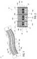
- FIG. 5illustrates exemplary removable portions of a cable.
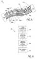
- FIG. 6illustrates an exemplary process for shielding the conductors.
- FIG. 7illustrates an exemplary electronic system.
- certain embodiments described hereinmay take the form of a cable that interconnects two electrical systems, components or subsystems.
- the cablemay be used in a computer to connect an input/output port to a storage device, a motherboard to a power supply, and so forth.
- the cablemay be used in a mobile or portable telephone, a stereo receiver, television and so forth. Accordingly, any sample operating embodiments that may be described herein should be regarded as illustrative and not limiting.
- One sample embodimentmay be a cable having an electrically conductive signal path formed thereon or therein.
- the signal pathmay be formed by traces of an electrically conductive material deposited on, formed on, or otherwise placed on a nonconductive layer.
- a nonconductive layermay be placed over these signal traces in whole or in part. That is, the nonconductive layer may not extend across an entire width or along an entire length of the cable depending on the electrical characteristics of the signal trace.
- Signal tracesare referred to herein as “conductors.”
- FIG. 1illustrates an exemplary cable 100 that may include multiple conductors 105 A-H.
- the cable 100may couple together two electronic components 110 and 115 .
- this couplingmay be electrical in nature and the conductors 105 A-H may be made from electrically conductive materials such as copper, aluminum, and/or tin to name but a few.
- the cable 100generally establishes a signal path between two electrical components and thus may permit a first electrical component 110 to send and receive signals to and/or from a second electrical component 115 via the conductors 105 A-H.
- FIG. 1shows only two electronic components 110 and 115 , it should be appreciated that any number of electronic components may be coupled together using a suitably configured cable 100 .
- the electronic components 110 and 115may be sub-portions of a common electrical device and located within a common housing. In other embodiments, the electronic components 110 and 115 may be located in physically separate locations.
- componentis intended to refer both to subsystems of a larger electrical or electronic device (such as the hard drive, input/output connectors, motherboard, and processor of a computer) and stand-alone devices (such as the computer taken as a whole).
- devicegenerally refers to an overall apparatus or system into which a component may be integrated or which may include one or more components.
- the electrical signals being conveyed over the conductors 105 A-Hmay have different EMI parameters.
- some conductorsmay convey electrical signals that change with respect to time, such as clock or data signals
- other conductorsmay include electrical signals that are relatively constant with respect to time, such as power supply signals.
- Signals that change with respect to timeare more likely to emanate EMI (i.e., are more noisy) than those that are constant with respect to time.
- some of the signals being conveyed over the conductors 105 A-Hmay be more susceptible to EMI than others.
- the signals conveyed between the components 110 and 115may high speed data signals that leave little room for signal error due to EMI. Because the electrical signals being conveyed over the conductors 105 A-H may have different EMI parameters, in some embodiments, the content of the signal being conveyed via the conductors 105 A-H may be used to determine selective shielding for the conductors 105 A-H.
- the conductor 105 Aincludes a signal that emanates relatively high EMI levels it may be shielded.
- the conductor 105 Hincludes a signal with relatively low EMI levels it may be unshielded.
- the conductor 105 Aconveys a signal that is particularly susceptible to EMI it may be shielded, whereas if the signal in conductor 105 H is relatively insensitive to EMI it may be unshielded.
- the actual EMI levels sufficient to consider a signal particularly susceptible to EMI or particularly insensitive to EMImay vary between embodiments and may be related to levels imposed by governmental regulation.
- shielded cablesmay be more rigid and less flexible than unshielded cables.
- a more flexible and less rigid cable 100may be implemented and while providing desired levels of EMI protection. Accordingly, the environment in which the cable is placed, as well as its operating requirements, may also be a factor in determining how many or how few conductors are shielded. For example, a cable that is routed between components 110 , 115 in such a manner that it must bend at relatively sharp angles in a relatively short distance may be less shielded than a straight-run cable.
- the cable 100may take a variety of physical forms. Some embodiments may implement the cable 100 as a flat ribbon-type cable where the conductors 105 A-H are made of metallic conductive material such as copper, aluminum, and/or tin to name but a few. Other embodiments may implement the cable 100 using printed circuit board (PCB) technology such as microstrip and/or stripline technology.
- PCBprinted circuit board
- FIG. 2illustrates a cross section of the cable 100 (taken along the line A-A′ of FIG. 1 ), showing the cable 100 formed of a combination of both stripline and microstrip technology.
- “Microstrip”refers to a type of transmission line that may be fabricated using PCB technology wherein the conductors may be separated from a ground plane using a substrate made of dielectric material.
- Section 205illustrates an exemplary microstrip implementation where the conductors 105 C-E may be separated from a ground plane 207 by a dielectric layer 208 .
- striplinerefers to a type of transmission line that may be fabricated using PCB technology with the conductors sandwiched between two parallel ground planes using a substrate made of dielectric material.
- Sections 210 A-Billustrate an exemplary stripline implementation where the conductors 105 A-B and 105 F-H may be separated from the ground planes 207 , 215 , and 220 by dielectric layers 225 and 230 respectively.
- one or more the dielectric layers 208 , 225 , and/or 230may include first and second portions.
- dielectric 208may include 208 A and 208 B (not specifically shown in FIG. 2 ) above and below a dielectric boundary line 226 .
- each dielectricmay be deposited in layers above and beneath the conductors.
- the first and second upper ground planes 215 and 220may connect to the lower ground plane 207 through one or more vertically connecting vias 221 - 224 .
- the vias 221 - 224in combination with the upper and lower ground planes 207 , 215 , 220 , may effectively define the cable 100 as incorporating different microstrip sections 205 and stripline sections 210 A-B.
- the division between the microstrip and stripline sections shownis an example only. Alternative embodiments may include more or fewer of each type of section.
- the width of the conductor, the thickness of the dielectric, and the relative permittivity of the dielectricmay determine the characteristic impedance of the conductor.
- the stripline conductors 105 A-B and 105 F-Hmay be equally spaced between the ground planes.
- the striplinesmay be spaced asymmetrically with respect to the ground planes of the stripline sections in which or on which they are formed.
- dielectric usedmay vary to suit the particular implementation.
- dielectric layers 208 , 225 and 230may be built using FR4 type dielectric.
- substances that have better high frequency performancesuch as alumina, may be used to build the dielectric layers 208 , 225 and 230 .
- the stripline sections 210 A-Bmay provide better electrical isolation (e.g., isolation from EMI and/or prevention of EMI emission) for the conductors 105 A-B and 105 F-H than the microstrip section 205 may provide for that section's respective conductors 105 C-E.
- the microstrip section 205may be less rigid and more flexible than the stripline sections 210 A-B.
- the cable 100may be configured such that the microstrip sections are implemented over conductors that typically carry a signal which is relatively constant with respect to time and the stripline sections are implemented over conductors that carry a signal typically changing relatively frequently with respect to time.
- Exemplary signals that are relatively constant with respect to timemay include power supply signals and/or real time clock signals (i.e., 32 kHz).
- Exemplary signals that change relatively frequently with respect to timemay include high speed serial communication signals.
- signals that are more susceptible to EMImay be shielded by implementing stripline sections over conductors carrying these signals.
- conductors 105 A-Bmay convey differential signals, where the conductor 105 A may convey the positive version of the differential signals and the conductor 105 B may convey the negative version of the differential signal.
- Differential signalsoften are used to reduce the amount of noise induced in the signal by representing the signal of interest as the difference between the positive and negative versions of the differential signal, the notion being that EMI introduced in the conductor 105 A will likewise be introduced in the conductor 105 B so that the difference between them will cancel out this noise.
- the signal-to-noise ratio of the differential signalsmay be increased.
- their power levelmay be decreased.
- FIG. 3depicts another exemplary cross section of the cable 100 taken along line B-B′ of FIG. 1 .
- the cross section taken along B-B′may be located in a different portion of the cable 100 than the cross section taken along the line A-A′.
- the upper ground plane 220may be removed along with vias 221 and 222 to form a microstrip section 305 along at least this portion of the cable 100 .
- the cross sections shown in FIGS. 2 and 3may be part of the same cable 100 despite having different stripline-microstrip configurations over the length of the cable 100 .
- certain conductorsmay be shielded for a portion or the entirety of the cable's length.
- the cable 100may be fabricated so as to optimize the flexibility and the EMI shielding based upon the specific signals being conveyed on the various conductors.
- FIG. 4illustrates a cable 100 implementing the exemplary shielding configurations shown in FIGS. 2 and 3 .
- the microstrip portions 205 and 305 from FIGS. 2 and 3are indicated using a hashed pattern to represent that the ground planes are not present over these portions of cable 100 in this embodiment.
- the particular shielding configurationsmay be determined after the cable 100 is coupled between the electrical components 110 and 115 . This may provide more options for designers of the electronic components in that a single type of cable may be purchased and custom configured based on the particular needs of the electronic components and/or physical flexibility requirements of the cable.
- the shieldingmay be configured to be selectively removable based upon the content of the signals in the conductors.
- FIG. 5illustrates exemplary removable shield portions 505 and 510 that may be selectively removed from the cable 100 and provide additional flexibility to the cable 100 .
- one or more of these removable portionsmay be selectively removed. That is, certain segments of the shield portions (e.g., EMI shield or ground planes) may be peeled away or otherwise removed if unnecessary.
- the shield portionsmay be perforated or otherwise weakened at certain areas, lines and/or segments to facilitate their selective removal.
- FIG. 6illustrates an exemplary process 600 for forming a cable including one or more selectively shielded conductors.
- the plurality of conductorsmay be formed.
- one or more metal conductorsmay be deposited on a common substrate material, such as by using metal deposition techniques.
- a dielectric materialmay be disposed about the conductors per operation 610 .
- the dielectric material deposition in operation 610may be disposed using deposition techniques.
- the conductors and dielectric of operations 605 and 610may formed using a series of deposition and etching techniques.
- the shielding layers and/or ground planesmay be selectively disposed about the conductors such that some portions of the conductors have shielding while other portions of the conductors do not. This selective disposing of the shielding may be based upon a variety of cable specific factors such as, the signals being carried in the various conductors of the cable, the spacing of the conductors, and/or physical routing considerations of the cable in the electrical system to name but a few.
- the cablewhen designing the cable, the cable may be tested in an electrical system (such as the computer system described below with regard to FIG. 7 ) per operation 620 . In this manner, if the cable does not meet desired flexibility requirements, then shielding may be removed as shown in FIG. 5 .
- the cable 100may be implemented in a variety of different electronic devices.
- FIG. 7shows an exemplary computer system 700 , where the cable 100 may be used to couple together two or more of the computer system's subcomponents.
- the cable 100also may be used to couple the computer system 700 to other computer systems.
- the computer system 700may be an implementation of an enterprise level computer such as a blade-type server, and the cable 100 may be used to couple it to one or more additional blade-type servers within an enterprise.
- the computer system 700may be a personal computer and/or a handheld electronic device and the cable 100 may couple together various sub-components of the electronic device.
- a keyboard 710 and mouse 711may be coupled to the computer system 700 via a system bus 718 .
- the keyboard 710 and mouse 711may introduce user input to computer system 700 and communicate that user input to a processor 713 .
- Other suitable input devicesmay be used in addition to, or in place of, mouse 711 and keyboard 710 .
- An input/output unit 719 (I/O) coupled to system bus 718represents such I/O elements as a printer, audio/video (A/V) I/O, etc.
- Computer 700also may include a video memory 714 , a main memory 715 and a mass storage 712 , all coupled to system bus 718 along with keyboard 710 , mouse 711 and processor 713 .
- Mass storage 712may include both fixed and removable media, such as magnetic, optical or magnetic optical storage systems and any other available mass storage technology.
- Bus 718may contain, for example, address lines for addressing video memory 714 or main memory 715 .
- System bus 718also includes, for example, a data bus for transferring data between and among the components, such as processor 713 , main memory 715 , video memory 714 and mass storage 712 .
- Video memory 714may be a dual-ported video random access memory.
- One port of video memory 714is coupled to video amplifier 716 , which is used to drive a monitor 717 .
- Monitor 717may be any type of monitor suitable for displaying graphic images, such as a cathode ray tube monitor (CRT), flat panel, or liquid crystal display (LCD) monitor or any other suitable data presentation device.
- CTRcathode ray tube monitor
- LCDliquid crystal display
- processor 713is a SPARC® microprocessor from Sun Microsystems, Inc., or a microprocessor manufactured by Motorola, such as the 680XX0 processor, or a microprocessor manufactured by INTEL, such as the 80X86, PENTIUM or other suitable processor. Any other suitable microprocessor or microcomputer may be utilized, however.
- Computer 700also may include a communication interface 720 coupled to bus 718 .
- Communication interface 720provides a two-way data communication coupling via a network link.
- communication interface 720may be an integrated services digital network (ISDN) card or a modem, a local area network (LAN) card, or a cable modem or wireless interface.
- ISDNintegrated services digital network
- LANlocal area network
- cable modemor wireless interface.
- communication interface 720sends and receives electrical, electromagnetic or optical signals which carry digital data streams representing various types of information.
- Code received by computer 700may be executed by processor 713 as it is received, and/or stored in mass storage 712 , or other non-volatile storage for later execution. In this manner, computer 700 may obtain application code in a variety of forms.
- Application codemay be embodied in any form of computer program product such as a medium configured to store or transport computer readable code or data, or in which computer readable code or data may be embedded. Examples of computer program products include CD-ROM discs, ROM cards, floppy disks, magnetic tapes, computer hard drives, servers on a network, and solid state memory devices.
- the cable 100may couple electronic devices together optically, and the conductors 105 A-H may be made from an optically conductive material, such as glass, plastic, and/or quartz to name but a few.
Landscapes
- Insulated Conductors (AREA)
Abstract
Description
Claims (19)
Priority Applications (1)
| Application Number | Priority Date | Filing Date | Title |
|---|---|---|---|
| US12/193,850US8110744B2 (en) | 2008-08-19 | 2008-08-19 | Flexible shielded cable |
Applications Claiming Priority (1)
| Application Number | Priority Date | Filing Date | Title |
|---|---|---|---|
| US12/193,850US8110744B2 (en) | 2008-08-19 | 2008-08-19 | Flexible shielded cable |
Publications (2)
| Publication Number | Publication Date |
|---|---|
| US20100044067A1 US20100044067A1 (en) | 2010-02-25 |
| US8110744B2true US8110744B2 (en) | 2012-02-07 |
Family
ID=41695277
Family Applications (1)
| Application Number | Title | Priority Date | Filing Date |
|---|---|---|---|
| US12/193,850Expired - Fee RelatedUS8110744B2 (en) | 2008-08-19 | 2008-08-19 | Flexible shielded cable |
Country Status (1)
| Country | Link |
|---|---|
| US (1) | US8110744B2 (en) |
Cited By (10)
| Publication number | Priority date | Publication date | Assignee | Title |
|---|---|---|---|---|
| US20110290541A1 (en)* | 2010-05-28 | 2011-12-01 | Shih-Kun Yeh | Flexible flat cable |
| US20120020416A1 (en)* | 2009-03-30 | 2012-01-26 | Panasonic Corporation | Flexible cable and transmission system |
| US8690410B2 (en) | 2010-05-12 | 2014-04-08 | Apple Inc. | Display element including microperforations |
| US8915633B2 (en) | 2009-06-01 | 2014-12-23 | Apple Inc. | White point adjustment for multicolor keyboard backlight |
| US9041563B2 (en) | 2010-06-11 | 2015-05-26 | Apple Inc. | Legend highlighting |
| US9086733B2 (en) | 2010-07-19 | 2015-07-21 | Apple Inc. | Illumination of input device |
| US9563239B2 (en) | 2012-09-10 | 2017-02-07 | Apple Inc. | Internal computer assembly features and methods |
| US10427439B2 (en) | 2017-09-11 | 2019-10-01 | Apple Inc. | Substrate marking for sealing surfaces |
| US10951053B2 (en) | 2018-09-10 | 2021-03-16 | Apple Inc. | Portable electronic device |
| US12166911B2 (en) | 2021-03-02 | 2024-12-10 | Apple Inc. | Handheld electronic device |
Families Citing this family (16)
| Publication number | Priority date | Publication date | Assignee | Title |
|---|---|---|---|---|
| US9086737B2 (en)* | 2006-06-15 | 2015-07-21 | Apple Inc. | Dynamically controlled keyboard |
| US7845953B2 (en) | 2008-01-07 | 2010-12-07 | Apple Inc. | Input/output connector and housing |
| US8067701B2 (en)* | 2008-01-07 | 2011-11-29 | Apple Inc. | I/O connectors with extendable faraday cage |
| KR101722402B1 (en)* | 2009-01-09 | 2017-04-04 | 삼성디스플레이 주식회사 | Light source unit and display device having the same |
| US8378972B2 (en)* | 2009-06-01 | 2013-02-19 | Apple Inc. | Keyboard with increased control of backlit keys |
| US9247611B2 (en) | 2009-06-01 | 2016-01-26 | Apple Inc. | Light source with light sensor |
| US20100306683A1 (en)* | 2009-06-01 | 2010-12-02 | Apple Inc. | User interface behaviors for input device with individually controlled illuminated input elements |
| US8654524B2 (en) | 2009-08-17 | 2014-02-18 | Apple Inc. | Housing as an I/O device |
| US8441790B2 (en) | 2009-08-17 | 2013-05-14 | Apple Inc. | Electronic device housing as acoustic input device |
| US8922530B2 (en) | 2010-01-06 | 2014-12-30 | Apple Inc. | Communicating stylus |
| US20110162894A1 (en)* | 2010-01-06 | 2011-07-07 | Apple Inc. | Stylus for touch sensing devices |
| US8624878B2 (en)* | 2010-01-20 | 2014-01-07 | Apple Inc. | Piezo-based acoustic and capacitive detection |
| US9275810B2 (en) | 2010-07-19 | 2016-03-01 | Apple Inc. | Keyboard illumination |
| US9756927B2 (en) | 2011-11-30 | 2017-09-12 | Apple Inc. | Mounting system for portable electronic device |
| US8904052B2 (en) | 2011-12-23 | 2014-12-02 | Apple Inc. | Combined input port |
| CN104135817B (en)* | 2014-06-17 | 2017-10-24 | 京东方科技集团股份有限公司 | Flexible PCB and preparation method thereof and capacitive touch display device |
Citations (102)
| Publication number | Priority date | Publication date | Assignee | Title |
|---|---|---|---|---|
| US3060790A (en) | 1959-02-02 | 1962-10-30 | Specialties Inc | Colorimeter and color sorting apparatus |
| US3754209A (en) | 1971-01-25 | 1973-08-21 | Computer Systems Eng Inc | Traffic signal control system |
| JPS58112263A (en) | 1981-12-25 | 1983-07-04 | Mitsubishi Electric Corp | Fuel cell |
| US4814552A (en) | 1987-12-02 | 1989-03-21 | Xerox Corporation | Ultrasound position input device |
| US4845311A (en) | 1988-07-21 | 1989-07-04 | Hughes Aircraft Company | Flexible coaxial cable apparatus and method |
| US4855740A (en) | 1986-10-01 | 1989-08-08 | Yamaha Corporation | Keyboard |
| US5040479A (en) | 1990-07-24 | 1991-08-20 | Apollo Plastics Corporation | Illuminated multiple color button and method of manufacturing the same |
| US5081482A (en) | 1988-05-16 | 1992-01-14 | Minolta Camera Kabushiki Kaisha | Ic card and camera for use therewith |
| US5245734A (en) | 1989-11-14 | 1993-09-21 | Battelle Memorial Institute | Multilayer piezoelectric actuator stack and method for its manufacture |
| US5317105A (en) | 1992-12-18 | 1994-05-31 | Alcatel Network Systems, Inc. | EMI/RFI gasket apparatus |
| US5342991A (en)* | 1993-03-03 | 1994-08-30 | The Whitaker Corporation | Flexible hybrid branch cable |
| US5365461A (en) | 1992-04-30 | 1994-11-15 | Microtouch Systems, Inc. | Position sensing computer input device |
| US5371901A (en) | 1991-07-08 | 1994-12-06 | Motorola, Inc. | Remote voice control system |
| US5583560A (en) | 1993-06-22 | 1996-12-10 | Apple Computer, Inc. | Method and apparatus for audio-visual interface for the selective display of listing information on a display |
| US5726645A (en) | 1993-09-28 | 1998-03-10 | Sony Corporation | Remote controller capable of selecting and setting preset data |
| US5770898A (en) | 1996-03-29 | 1998-06-23 | Siemens Business Communication Systems, Inc. | Modular power management system with common EMC barrier |
| US5815379A (en) | 1997-06-09 | 1998-09-29 | Compaq Computer Corporation | Pivotable computer access door structure having concealed, break-away hinge mechanism |
| US5831601A (en) | 1995-06-07 | 1998-11-03 | Nview Corporation | Stylus position sensing and digital camera with a digital micromirror device |
| US5951908A (en) | 1998-01-07 | 1999-09-14 | Alliedsignal Inc. | Piezoelectrics and related devices from ceramics dispersed in polymers |
| US5975953A (en) | 1997-08-29 | 1999-11-02 | Hewlett-Packard Company | EMI by-pass gasket for shielded connectors |
| US6130822A (en) | 1997-06-09 | 2000-10-10 | Compaq Computer Corporation | Pivotable computer access door structure having concealed, Break-away hinge mechanism |
| US6180048B1 (en) | 1996-12-06 | 2001-01-30 | Polymatech Co., Ltd. | Manufacturing method of color keypad for a contact of character illumination rubber switch |
| FR2801402A1 (en) | 1999-11-22 | 2001-05-25 | Charles Moransais | Universal remote control unit setting/configuration method having control unit with sensor detecting appliance state and coded sequences appliance makes corresponding passed/stopped when remote unit switch off detected. |
| WO2001069567A2 (en) | 2000-03-15 | 2001-09-20 | Glen Mclean Harris | State-based remote control system |
| US6337678B1 (en) | 1999-07-21 | 2002-01-08 | Tactiva Incorporated | Force feedback computer input and output device with coordinated haptic elements |
| US6347882B1 (en) | 2000-08-16 | 2002-02-19 | Motorola, Inc. | Display backlighting system |
| KR20020013984A (en) | 2000-08-10 | 2002-02-25 | 한명수,한영수 | A Telephone system using a speech recognition in a personal computer system, and a base telephone set therefor |
| WO2002073587A1 (en) | 2001-03-09 | 2002-09-19 | Immersion Corporation | Haptic interface for laptop computers and other portable devices |
| US6525929B2 (en) | 2001-01-25 | 2003-02-25 | Dell Products L.P. | Computer chassis door with position damping detent hinge |
| US6532446B1 (en) | 1999-11-24 | 2003-03-11 | Openwave Systems Inc. | Server based speech recognition user interface for wireless devices |
| KR20030035305A (en) | 2001-10-31 | 2003-05-09 | 삼성전자주식회사 | Stylus with exterior-type camera lens module and portable telephone therewith |
| US6611253B1 (en) | 2000-09-19 | 2003-08-26 | Harel Cohen | Virtual input environment |
| US20030174072A1 (en) | 2002-03-11 | 2003-09-18 | Tahl Salomon | Systems and methods employing changeable touch-key |
| US20030210221A1 (en) | 2002-05-08 | 2003-11-13 | Milivoje Aleksic | Portable device for providing LCD display and method thereof |
| US6713672B1 (en) | 2001-12-07 | 2004-03-30 | Laird Technologies, Inc. | Compliant shaped EMI shield |
| US6717073B2 (en) | 2000-12-29 | 2004-04-06 | Intel Corporation | Wireless display systems, styli, and associated methods |
| US6738264B2 (en) | 1999-10-20 | 2004-05-18 | Fujitsu Limited | Foldaway electronic device and flexible cable for same |
| US6794992B1 (en) | 2000-12-29 | 2004-09-21 | Bellsouth Intellectual Property Corporation | Integrated remote control unit for operating a television and a video game unit |
| US6800805B2 (en) | 2002-12-19 | 2004-10-05 | Nec Corporation | Noise suppressing structure for shielded cable |
| US20040230912A1 (en) | 2003-05-13 | 2004-11-18 | Microsoft Corporation | Multiple input language selection |
| US20040238195A1 (en) | 2003-05-28 | 2004-12-02 | Craig Thompson | Self-mounting EMI shielding gasket for metal shell electronic apparatus connectors |
| US6834294B1 (en) | 1999-11-10 | 2004-12-21 | Screenboard Technologies Inc. | Methods and systems for providing and displaying information on a keyboard |
| US6836651B2 (en) | 1999-06-21 | 2004-12-28 | Telespree Communications | Portable cellular phone system having remote voice recognition |
| US20050110777A1 (en) | 2003-11-25 | 2005-05-26 | Geaghan Bernard O. | Light-emitting stylus and user input device using same |
| US6914551B2 (en) | 2002-04-12 | 2005-07-05 | Apple Computer, Inc. | Apparatus and method to facilitate universal remote control |
| WO2005065034A2 (en) | 2004-01-05 | 2005-07-21 | Dikla Hasson | System and method for improving typing skills |
| US20050162411A1 (en) | 2002-06-07 | 2005-07-28 | Berkel Van Cornelis | Input system |
| US20050200286A1 (en) | 2004-02-02 | 2005-09-15 | Arne Stoschek | Operating element for a vehicle |
| US20050200557A1 (en) | 2004-03-09 | 2005-09-15 | Sony Corporation | Flat cable, flat cable sheet, and flat cable sheet producing method |
| US6995752B2 (en) | 2001-11-08 | 2006-02-07 | Koninklijke Philips Electronics N.V. | Multi-point touch pad |
| US6998594B2 (en) | 2002-06-25 | 2006-02-14 | Koninklijke Philips Electronics N.V. | Method for maintaining light characteristics from a multi-chip LED package |
| US20060042820A1 (en) | 2004-08-27 | 2006-03-02 | Gwun-Jin Lin | Signal transmission cable adapted to pass through hinge assembly |
| US20060151198A1 (en)* | 2002-03-11 | 2006-07-13 | Salvatore Bracaleone | Quadrax to twinax conversion apparatus and method |
| US7088261B2 (en) | 2000-08-29 | 2006-08-08 | Lailai Capital Corp. | Traffic signal light having ambient light detection |
| US7133030B2 (en) | 2003-07-31 | 2006-11-07 | Microsoft Corporation | Context sensitive labels for a hardware input device |
| US7167083B2 (en) | 2002-09-30 | 2007-01-23 | International Business Machines Corporation | Recording and indicating the state of an apparatus remotely |
| US20070050054A1 (en) | 2005-08-26 | 2007-03-01 | Sony Ericssson Mobile Communications Ab | Mobile communication terminal with virtual remote control |
| US20070124772A1 (en) | 2005-11-30 | 2007-05-31 | Bennett James D | Universal parallel television remote control |
| GB2433211A (en) | 2005-12-13 | 2007-06-20 | Saj Muzaffar | Interactive DVD game system using multiple remote controls |
| US20070174058A1 (en) | 2005-08-09 | 2007-07-26 | Burns Stephen S | Voice controlled wireless communication device system |
| US20070195068A1 (en) | 2006-02-23 | 2007-08-23 | Scriptel Corporation | Pen apparatus and method of assembly |
| US7274303B2 (en) | 2002-03-01 | 2007-09-25 | Universal Electronics Inc. | Power strip with control and monitoring functionality |
| US20070285405A1 (en) | 2006-02-13 | 2007-12-13 | Rehm Peter H | Relative-position, absolute-orientation sketch pad and optical stylus for a personal computer |
| US7315908B2 (en) | 2004-04-09 | 2008-01-01 | Gateway Inc. | Computer and RFID-based input devices |
| US20080001787A1 (en) | 2006-06-15 | 2008-01-03 | Apple Inc. | Dynamically controlled keyboard |
| EP1881513A1 (en) | 2003-10-08 | 2008-01-23 | Research In Motion Limited | Selective keyboard illumination |
| US7347712B2 (en) | 2003-01-27 | 2008-03-25 | Dormina Uk Limited | Safety covers for electric sockets and the like |
| US20080150917A1 (en) | 2006-12-20 | 2008-06-26 | 3M Innovative Properties Company | Oscillator circuit for use in an untethered stylus |
| US7417624B2 (en) | 2003-02-14 | 2008-08-26 | Duff Michael J | Zero-force key activation keyboard with dynamic individual key illumination |
| US7446303B2 (en) | 2007-01-31 | 2008-11-04 | Avago Technologies Ecbu Ip (Singapore) Pte. Ltd | Ambient light sensing using a color sensor |
| US7453441B1 (en) | 2008-03-31 | 2008-11-18 | International Business Machines Corporation | Method and system for intelligent keyboard illumination |
| US20080291620A1 (en) | 2007-05-23 | 2008-11-27 | John Difonzo | Electronic device with a ceramic component |
| US7470866B2 (en) | 2004-11-18 | 2008-12-30 | Jemic Shielding Technology | Electrically conductive gasket |
| US20090002328A1 (en) | 2007-06-26 | 2009-01-01 | Immersion Corporation, A Delaware Corporation | Method and apparatus for multi-touch tactile touch panel actuator mechanisms |
| US7473139B2 (en) | 2006-08-08 | 2009-01-06 | International Business Machines Corporation | Universal EMC gasket |
| US20090009489A1 (en) | 2006-01-24 | 2009-01-08 | Yong-Jik Lee | Portable Apparatus and Method for Inputing Data With Electronic Pen and Transmitting Data |
| EP2017694A1 (en) | 2007-07-09 | 2009-01-21 | Vodafone Holding GmbH | Keyboard for an electronic device, input device for an electronic device, electronic device and method for illuminating keys of an electronic device |
| US20090035600A1 (en)* | 2007-08-01 | 2009-02-05 | Chin-Chih Chiang | Flat cable covering means for generating different impendances |
| US7489308B2 (en) | 2003-02-14 | 2009-02-10 | Microsoft Corporation | Determining the location of the tip of an electronic stylus |
| US20090104898A1 (en) | 2001-02-09 | 2009-04-23 | Harris Scott C | A telephone using a connection network for processing data remotely from the telephone |
| WO2009059479A1 (en) | 2007-11-07 | 2009-05-14 | Pohsien Chiu | Input devices with virtual input interfaces |
| US20090167704A1 (en) | 2007-12-31 | 2009-07-02 | Apple Inc. | Multi-touch display screen with localized tactile feedback |
| US7557690B2 (en) | 2003-08-12 | 2009-07-07 | Overhead Door Corporation | Device including light emitting diode as light sensor and light source |
| US20090173533A1 (en) | 2008-01-07 | 2009-07-09 | Apple Inc. | Flexible data cable |
| US20090176391A1 (en) | 2008-01-07 | 2009-07-09 | Apple Inc. | Input/output connector and housing |
| US20090222270A2 (en) | 2006-02-14 | 2009-09-03 | Ivc Inc. | Voice command interface device |
| US7598686B2 (en) | 1997-12-17 | 2009-10-06 | Philips Solid-State Lighting Solutions, Inc. | Organic light emitting diode methods and apparatus |
| US20090277763A1 (en) | 2007-02-28 | 2009-11-12 | Research In Motion Limited | Backlighted key for a keypad of an electronic device |
| WO2009136929A1 (en) | 2008-05-08 | 2009-11-12 | Hewlett-Packard Development Company, L.P. | Wear-resistant keyboards methods for producing same |
| US20090283342A1 (en) | 1998-10-20 | 2009-11-19 | Synaptics Incorporated | Finger/stylus touch pad |
| US7634263B2 (en) | 2006-01-30 | 2009-12-15 | Apple Inc. | Remote control of electronic devices |
| US7646379B1 (en) | 2005-01-10 | 2010-01-12 | Motion Computing, Inc. | Wireless and contactless electronic input stylus having at least one button with optical scan and programmable pointer functionality |
| US20100053468A1 (en) | 2008-08-30 | 2010-03-04 | Mike Harvill | Device ir setup using ir detector |
| US20100081375A1 (en) | 2008-09-30 | 2010-04-01 | Apple Inc. | System and method for simplified control of electronic devices |
| US7710397B2 (en) | 2005-06-03 | 2010-05-04 | Apple Inc. | Mouse with improved input mechanisms using touch sensors |
| US20100214226A1 (en) | 2009-02-23 | 2010-08-26 | International Business Machines Corporation | System and method for semi-transparent display of hands over a keyboard in real-time |
| US20100301755A1 (en) | 2009-06-01 | 2010-12-02 | Apple Inc. | Light source with light sensor |
| US20100302169A1 (en) | 2009-06-01 | 2010-12-02 | Apple Inc. | Keyboard with increased control of backlit keys |
| US20100306683A1 (en) | 2009-06-01 | 2010-12-02 | Apple Inc. | User interface behaviors for input device with individually controlled illuminated input elements |
| US20100300856A1 (en) | 2009-06-01 | 2010-12-02 | Apple Inc. | White point adjustment for multicolor keyboard backlight |
| US20110037734A1 (en) | 2009-08-17 | 2011-02-17 | Apple Inc. | Electronic device housing as acoustic input device |
| US20110038114A1 (en) | 2009-08-17 | 2011-02-17 | Apple Inc. | Housing as an i/o device |
Family Cites Families (1)
| Publication number | Priority date | Publication date | Assignee | Title |
|---|---|---|---|---|
| TWM368993U (en)* | 2009-05-26 | 2009-11-11 | Cal Comp Electronics & Comm Co | Driving circuit of light emitting diode and lighting apparatus |
- 2008
- 2008-08-19USUS12/193,850patent/US8110744B2/ennot_activeExpired - Fee Related
Patent Citations (104)
| Publication number | Priority date | Publication date | Assignee | Title |
|---|---|---|---|---|
| US3060790A (en) | 1959-02-02 | 1962-10-30 | Specialties Inc | Colorimeter and color sorting apparatus |
| US3754209A (en) | 1971-01-25 | 1973-08-21 | Computer Systems Eng Inc | Traffic signal control system |
| JPS58112263A (en) | 1981-12-25 | 1983-07-04 | Mitsubishi Electric Corp | Fuel cell |
| US4855740A (en) | 1986-10-01 | 1989-08-08 | Yamaha Corporation | Keyboard |
| US4814552A (en) | 1987-12-02 | 1989-03-21 | Xerox Corporation | Ultrasound position input device |
| US5081482A (en) | 1988-05-16 | 1992-01-14 | Minolta Camera Kabushiki Kaisha | Ic card and camera for use therewith |
| US4845311A (en) | 1988-07-21 | 1989-07-04 | Hughes Aircraft Company | Flexible coaxial cable apparatus and method |
| US5245734A (en) | 1989-11-14 | 1993-09-21 | Battelle Memorial Institute | Multilayer piezoelectric actuator stack and method for its manufacture |
| US5040479A (en) | 1990-07-24 | 1991-08-20 | Apollo Plastics Corporation | Illuminated multiple color button and method of manufacturing the same |
| US5371901A (en) | 1991-07-08 | 1994-12-06 | Motorola, Inc. | Remote voice control system |
| US5365461A (en) | 1992-04-30 | 1994-11-15 | Microtouch Systems, Inc. | Position sensing computer input device |
| US5317105A (en) | 1992-12-18 | 1994-05-31 | Alcatel Network Systems, Inc. | EMI/RFI gasket apparatus |
| US5342991A (en)* | 1993-03-03 | 1994-08-30 | The Whitaker Corporation | Flexible hybrid branch cable |
| US5583560A (en) | 1993-06-22 | 1996-12-10 | Apple Computer, Inc. | Method and apparatus for audio-visual interface for the selective display of listing information on a display |
| US5726645A (en) | 1993-09-28 | 1998-03-10 | Sony Corporation | Remote controller capable of selecting and setting preset data |
| US5831601A (en) | 1995-06-07 | 1998-11-03 | Nview Corporation | Stylus position sensing and digital camera with a digital micromirror device |
| US5770898A (en) | 1996-03-29 | 1998-06-23 | Siemens Business Communication Systems, Inc. | Modular power management system with common EMC barrier |
| US6180048B1 (en) | 1996-12-06 | 2001-01-30 | Polymatech Co., Ltd. | Manufacturing method of color keypad for a contact of character illumination rubber switch |
| US5815379A (en) | 1997-06-09 | 1998-09-29 | Compaq Computer Corporation | Pivotable computer access door structure having concealed, break-away hinge mechanism |
| US6130822A (en) | 1997-06-09 | 2000-10-10 | Compaq Computer Corporation | Pivotable computer access door structure having concealed, Break-away hinge mechanism |
| US5975953A (en) | 1997-08-29 | 1999-11-02 | Hewlett-Packard Company | EMI by-pass gasket for shielded connectors |
| US7598686B2 (en) | 1997-12-17 | 2009-10-06 | Philips Solid-State Lighting Solutions, Inc. | Organic light emitting diode methods and apparatus |
| US5951908A (en) | 1998-01-07 | 1999-09-14 | Alliedsignal Inc. | Piezoelectrics and related devices from ceramics dispersed in polymers |
| US20090283342A1 (en) | 1998-10-20 | 2009-11-19 | Synaptics Incorporated | Finger/stylus touch pad |
| US6836651B2 (en) | 1999-06-21 | 2004-12-28 | Telespree Communications | Portable cellular phone system having remote voice recognition |
| US6337678B1 (en) | 1999-07-21 | 2002-01-08 | Tactiva Incorporated | Force feedback computer input and output device with coordinated haptic elements |
| US6738264B2 (en) | 1999-10-20 | 2004-05-18 | Fujitsu Limited | Foldaway electronic device and flexible cable for same |
| US6834294B1 (en) | 1999-11-10 | 2004-12-21 | Screenboard Technologies Inc. | Methods and systems for providing and displaying information on a keyboard |
| FR2801402A1 (en) | 1999-11-22 | 2001-05-25 | Charles Moransais | Universal remote control unit setting/configuration method having control unit with sensor detecting appliance state and coded sequences appliance makes corresponding passed/stopped when remote unit switch off detected. |
| US6532446B1 (en) | 1999-11-24 | 2003-03-11 | Openwave Systems Inc. | Server based speech recognition user interface for wireless devices |
| WO2001069567A2 (en) | 2000-03-15 | 2001-09-20 | Glen Mclean Harris | State-based remote control system |
| KR20020013984A (en) | 2000-08-10 | 2002-02-25 | 한명수,한영수 | A Telephone system using a speech recognition in a personal computer system, and a base telephone set therefor |
| US6347882B1 (en) | 2000-08-16 | 2002-02-19 | Motorola, Inc. | Display backlighting system |
| US7088261B2 (en) | 2000-08-29 | 2006-08-08 | Lailai Capital Corp. | Traffic signal light having ambient light detection |
| US6611253B1 (en) | 2000-09-19 | 2003-08-26 | Harel Cohen | Virtual input environment |
| US6794992B1 (en) | 2000-12-29 | 2004-09-21 | Bellsouth Intellectual Property Corporation | Integrated remote control unit for operating a television and a video game unit |
| US6717073B2 (en) | 2000-12-29 | 2004-04-06 | Intel Corporation | Wireless display systems, styli, and associated methods |
| US6525929B2 (en) | 2001-01-25 | 2003-02-25 | Dell Products L.P. | Computer chassis door with position damping detent hinge |
| US20090104898A1 (en) | 2001-02-09 | 2009-04-23 | Harris Scott C | A telephone using a connection network for processing data remotely from the telephone |
| WO2002073587A1 (en) | 2001-03-09 | 2002-09-19 | Immersion Corporation | Haptic interface for laptop computers and other portable devices |
| KR20030035305A (en) | 2001-10-31 | 2003-05-09 | 삼성전자주식회사 | Stylus with exterior-type camera lens module and portable telephone therewith |
| US6995752B2 (en) | 2001-11-08 | 2006-02-07 | Koninklijke Philips Electronics N.V. | Multi-point touch pad |
| US6713672B1 (en) | 2001-12-07 | 2004-03-30 | Laird Technologies, Inc. | Compliant shaped EMI shield |
| US7274303B2 (en) | 2002-03-01 | 2007-09-25 | Universal Electronics Inc. | Power strip with control and monitoring functionality |
| US20060151198A1 (en)* | 2002-03-11 | 2006-07-13 | Salvatore Bracaleone | Quadrax to twinax conversion apparatus and method |
| US20030174072A1 (en) | 2002-03-11 | 2003-09-18 | Tahl Salomon | Systems and methods employing changeable touch-key |
| US6914551B2 (en) | 2002-04-12 | 2005-07-05 | Apple Computer, Inc. | Apparatus and method to facilitate universal remote control |
| US20030210221A1 (en) | 2002-05-08 | 2003-11-13 | Milivoje Aleksic | Portable device for providing LCD display and method thereof |
| US20050162411A1 (en) | 2002-06-07 | 2005-07-28 | Berkel Van Cornelis | Input system |
| US6998594B2 (en) | 2002-06-25 | 2006-02-14 | Koninklijke Philips Electronics N.V. | Method for maintaining light characteristics from a multi-chip LED package |
| US7167083B2 (en) | 2002-09-30 | 2007-01-23 | International Business Machines Corporation | Recording and indicating the state of an apparatus remotely |
| US6800805B2 (en) | 2002-12-19 | 2004-10-05 | Nec Corporation | Noise suppressing structure for shielded cable |
| US7347712B2 (en) | 2003-01-27 | 2008-03-25 | Dormina Uk Limited | Safety covers for electric sockets and the like |
| US7417624B2 (en) | 2003-02-14 | 2008-08-26 | Duff Michael J | Zero-force key activation keyboard with dynamic individual key illumination |
| US7489308B2 (en) | 2003-02-14 | 2009-02-10 | Microsoft Corporation | Determining the location of the tip of an electronic stylus |
| US20040230912A1 (en) | 2003-05-13 | 2004-11-18 | Microsoft Corporation | Multiple input language selection |
| US20040238195A1 (en) | 2003-05-28 | 2004-12-02 | Craig Thompson | Self-mounting EMI shielding gasket for metal shell electronic apparatus connectors |
| US7133030B2 (en) | 2003-07-31 | 2006-11-07 | Microsoft Corporation | Context sensitive labels for a hardware input device |
| US7557690B2 (en) | 2003-08-12 | 2009-07-07 | Overhead Door Corporation | Device including light emitting diode as light sensor and light source |
| EP1881513A1 (en) | 2003-10-08 | 2008-01-23 | Research In Motion Limited | Selective keyboard illumination |
| US20050110777A1 (en) | 2003-11-25 | 2005-05-26 | Geaghan Bernard O. | Light-emitting stylus and user input device using same |
| WO2005065034A2 (en) | 2004-01-05 | 2005-07-21 | Dikla Hasson | System and method for improving typing skills |
| US20050200286A1 (en) | 2004-02-02 | 2005-09-15 | Arne Stoschek | Operating element for a vehicle |
| US7196273B2 (en) | 2004-03-09 | 2007-03-27 | Sony Corporation | Flat cable, flat cable sheet, and flat cable sheet producing method |
| US20050200557A1 (en) | 2004-03-09 | 2005-09-15 | Sony Corporation | Flat cable, flat cable sheet, and flat cable sheet producing method |
| US7315908B2 (en) | 2004-04-09 | 2008-01-01 | Gateway Inc. | Computer and RFID-based input devices |
| US20060042820A1 (en) | 2004-08-27 | 2006-03-02 | Gwun-Jin Lin | Signal transmission cable adapted to pass through hinge assembly |
| US7470866B2 (en) | 2004-11-18 | 2008-12-30 | Jemic Shielding Technology | Electrically conductive gasket |
| US7646379B1 (en) | 2005-01-10 | 2010-01-12 | Motion Computing, Inc. | Wireless and contactless electronic input stylus having at least one button with optical scan and programmable pointer functionality |
| US7710397B2 (en) | 2005-06-03 | 2010-05-04 | Apple Inc. | Mouse with improved input mechanisms using touch sensors |
| US20070174058A1 (en) | 2005-08-09 | 2007-07-26 | Burns Stephen S | Voice controlled wireless communication device system |
| US20070050054A1 (en) | 2005-08-26 | 2007-03-01 | Sony Ericssson Mobile Communications Ab | Mobile communication terminal with virtual remote control |
| US20070124772A1 (en) | 2005-11-30 | 2007-05-31 | Bennett James D | Universal parallel television remote control |
| GB2433211A (en) | 2005-12-13 | 2007-06-20 | Saj Muzaffar | Interactive DVD game system using multiple remote controls |
| US20090009489A1 (en) | 2006-01-24 | 2009-01-08 | Yong-Jik Lee | Portable Apparatus and Method for Inputing Data With Electronic Pen and Transmitting Data |
| US7634263B2 (en) | 2006-01-30 | 2009-12-15 | Apple Inc. | Remote control of electronic devices |
| US20070285405A1 (en) | 2006-02-13 | 2007-12-13 | Rehm Peter H | Relative-position, absolute-orientation sketch pad and optical stylus for a personal computer |
| US20090222270A2 (en) | 2006-02-14 | 2009-09-03 | Ivc Inc. | Voice command interface device |
| US20070195068A1 (en) | 2006-02-23 | 2007-08-23 | Scriptel Corporation | Pen apparatus and method of assembly |
| US20080001787A1 (en) | 2006-06-15 | 2008-01-03 | Apple Inc. | Dynamically controlled keyboard |
| US7473139B2 (en) | 2006-08-08 | 2009-01-06 | International Business Machines Corporation | Universal EMC gasket |
| US20080150917A1 (en) | 2006-12-20 | 2008-06-26 | 3M Innovative Properties Company | Oscillator circuit for use in an untethered stylus |
| US7446303B2 (en) | 2007-01-31 | 2008-11-04 | Avago Technologies Ecbu Ip (Singapore) Pte. Ltd | Ambient light sensing using a color sensor |
| US20090277763A1 (en) | 2007-02-28 | 2009-11-12 | Research In Motion Limited | Backlighted key for a keypad of an electronic device |
| US20080291620A1 (en) | 2007-05-23 | 2008-11-27 | John Difonzo | Electronic device with a ceramic component |
| US20090002328A1 (en) | 2007-06-26 | 2009-01-01 | Immersion Corporation, A Delaware Corporation | Method and apparatus for multi-touch tactile touch panel actuator mechanisms |
| EP2017694A1 (en) | 2007-07-09 | 2009-01-21 | Vodafone Holding GmbH | Keyboard for an electronic device, input device for an electronic device, electronic device and method for illuminating keys of an electronic device |
| US20090035600A1 (en)* | 2007-08-01 | 2009-02-05 | Chin-Chih Chiang | Flat cable covering means for generating different impendances |
| WO2009059479A1 (en) | 2007-11-07 | 2009-05-14 | Pohsien Chiu | Input devices with virtual input interfaces |
| US20090167704A1 (en) | 2007-12-31 | 2009-07-02 | Apple Inc. | Multi-touch display screen with localized tactile feedback |
| US20090173533A1 (en) | 2008-01-07 | 2009-07-09 | Apple Inc. | Flexible data cable |
| US20090173534A1 (en) | 2008-01-07 | 2009-07-09 | Apple Inc. | I/o connectors with extendable faraday cage |
| US20090176391A1 (en) | 2008-01-07 | 2009-07-09 | Apple Inc. | Input/output connector and housing |
| US7453441B1 (en) | 2008-03-31 | 2008-11-18 | International Business Machines Corporation | Method and system for intelligent keyboard illumination |
| WO2009136929A1 (en) | 2008-05-08 | 2009-11-12 | Hewlett-Packard Development Company, L.P. | Wear-resistant keyboards methods for producing same |
| US20100053468A1 (en) | 2008-08-30 | 2010-03-04 | Mike Harvill | Device ir setup using ir detector |
| US20100081375A1 (en) | 2008-09-30 | 2010-04-01 | Apple Inc. | System and method for simplified control of electronic devices |
| US20100214226A1 (en) | 2009-02-23 | 2010-08-26 | International Business Machines Corporation | System and method for semi-transparent display of hands over a keyboard in real-time |
| US20100301755A1 (en) | 2009-06-01 | 2010-12-02 | Apple Inc. | Light source with light sensor |
| US20100302169A1 (en) | 2009-06-01 | 2010-12-02 | Apple Inc. | Keyboard with increased control of backlit keys |
| US20100306683A1 (en) | 2009-06-01 | 2010-12-02 | Apple Inc. | User interface behaviors for input device with individually controlled illuminated input elements |
| US20100300856A1 (en) | 2009-06-01 | 2010-12-02 | Apple Inc. | White point adjustment for multicolor keyboard backlight |
| US20110037734A1 (en) | 2009-08-17 | 2011-02-17 | Apple Inc. | Electronic device housing as acoustic input device |
| US20110038114A1 (en) | 2009-08-17 | 2011-02-17 | Apple Inc. | Housing as an i/o device |
Non-Patent Citations (20)
| Title |
|---|
| Author Unknown, "Electronic Polymers, Semiconducting Polymers and Light Emitting Polymers-Focus of Polythiophene," Azom.com, http://www.azom.com/details.asp?ArticleID=2772, at least as early as Dec. 1, 2005. |
| Author Unknown, "Long Polymers Light Up LEDs," Physicsweb.org, http://www.physicsweb.org/articles/news/6/4/22/1, at least as early as Apr. 30, 2002. |
| Author Unknown, "Optimus Keyboard," Art.Lebedev Studio, http://www.artlebedev.com/portfolio/optimus/, at least as early as Dec. 1, 2005. |
| Author Unknown, "Optimus OLED Keyboard with Customizable Layout," Gear Live, http://www.gearlive.com/index.php/news.article/optimus-oled-keyboard-07131058/, at least as early as Dec. 1, 2005. |
| Author Unknown, "Optimus OLED Keyboard," Gizmodo: The Gadgets Weblog, http://www.gizmodo.com/gadgets/peripherals/input/optimus-oled-keyboard-112517.php, at least as early as Dec. 1, 2005. |
| Author Unknown, "Optimus Russian Keyboard," Primo Tech, http://www.primotechnology.com/index.php?art+articles/0705/optimus/index.htm, at least as early as Dec. 1, 2005. |
| Author Unknown, "Organic Light-Emitting Diode," Wikipedia.com, http://en.wikipedia.org/wiki/OLED, at least as early as Dec. 1, 2005. |
| Author Unknown, "Organic Polymers to Precede Nano Semi," EETimes.com, http://www.eet.com/story/OEG20030923S0055, at least as early as Dec. 1, 2005. |
| Author Unknown, "Physics News Update," American Institute of Physics, http://www.aip.org/pnu/1993/split/pnul148-3.htm, Oct. 19, 1993. |
| Author Unknown, "Polymer Light-Emitting Diodes," Philips Research-Technologies, http://www.research.philips.com/technologies/display/polyled/polyled/, at least as early as Dec. 1, 2005. |
| Author Unknown, "Re iPhone Universal Remote Control-Infrared Remote Control Accessory for iPhone and iPod touch," http://www.amazon.com/iPhone-Universal-Remote-Control-Accessory/dp/tech-data/B0038Za . . . , 2 pages, at least as early as Jul. 15, 2010. |
| Author Unknown, "RedEye mini Plug-in Universal Remote Adapter for iPhone, iPod touch and iPad," Amazon.com, 4 pages, date unknown. |
| Author Unknown, "What is OLED (Organic Light Emitting Diode)?," WiseGeek.com, http://www.wisegeek.com/what-is-an-oled.htm!referrer+adwords-campaign=oled-ad=024 . . . , at least as early as Dec. 1, 2005. |
| Author Unknown, "What is PLED?-A Word Definition from the Webopedia Computer Dictionary," http://www.webopedia.com/TERM/P/PLED/html, at least as early as Dec. 1, 2005. |
| Braun et al., "Transient Response of Passive Matrix Polymer LED Displays,"http://www.ee.calpoly.edu/~dbraun/papers/ICSM2000BraunEricksonK177.html, at least as early as Dec. 1, 2005. |
| Braun et al., "Transient Response of Passive Matrix Polymer LED Displays,"http://www.ee.calpoly.edu/˜dbraun/papers/ICSM2000BraunEricksonK177.html, at least as early as Dec. 1, 2005. |
| IBM, "Additional Functionality Added to Cell Phone via "Learning" Function Button," www.ip.com, 2 pages, Feb. 21, 2007. |
| Kwon et al., "Haptic Interferences for Mobile Devices: a Survey of the State of the Art," Telerobotics and Control Laboratory, KAIST (Korea Advanced Institute of Science and Technology, Korea, Dec. 11, 2007. |
| Motorola TDB et al., "Universal Programmable Remote Control/Telephone," www.ip.com, 2 pages, May 1, 1992. |
| Rojas, "Optimus Keyboard Trumped by the Display Keyboard?," http://www.engadget.com/2005/07/29/optimus-keyboard-trumped-by-the-display-keyboard/, Jul. 29, 2005. |
Cited By (14)
| Publication number | Priority date | Publication date | Assignee | Title |
|---|---|---|---|---|
| US20120020416A1 (en)* | 2009-03-30 | 2012-01-26 | Panasonic Corporation | Flexible cable and transmission system |
| US8669483B2 (en)* | 2009-03-30 | 2014-03-11 | Panasonic Corporation | Flexible cable and transmission system |
| US8915633B2 (en) | 2009-06-01 | 2014-12-23 | Apple Inc. | White point adjustment for multicolor keyboard backlight |
| US8690410B2 (en) | 2010-05-12 | 2014-04-08 | Apple Inc. | Display element including microperforations |
| US20110290541A1 (en)* | 2010-05-28 | 2011-12-01 | Shih-Kun Yeh | Flexible flat cable |
| US9041563B2 (en) | 2010-06-11 | 2015-05-26 | Apple Inc. | Legend highlighting |
| US9086733B2 (en) | 2010-07-19 | 2015-07-21 | Apple Inc. | Illumination of input device |
| US9563239B2 (en) | 2012-09-10 | 2017-02-07 | Apple Inc. | Internal computer assembly features and methods |
| US10427439B2 (en) | 2017-09-11 | 2019-10-01 | Apple Inc. | Substrate marking for sealing surfaces |
| US10486449B2 (en) | 2017-09-11 | 2019-11-26 | Apple Inc. | Structures for securing operational components in a portable electronic device |
| US10696078B2 (en) | 2017-09-11 | 2020-06-30 | Apple Inc. | Space-efficient flex cable with improved signal integrity for a portable electronic device |
| US10787014B2 (en) | 2017-09-11 | 2020-09-29 | Apple Inc. | Thermally conductive structure for dissipating heat in a portable electronic device |
| US10951053B2 (en) | 2018-09-10 | 2021-03-16 | Apple Inc. | Portable electronic device |
| US12166911B2 (en) | 2021-03-02 | 2024-12-10 | Apple Inc. | Handheld electronic device |
Also Published As
| Publication number | Publication date |
|---|---|
| US20100044067A1 (en) | 2010-02-25 |
Similar Documents
| Publication | Publication Date | Title |
|---|---|---|
| US8110744B2 (en) | Flexible shielded cable | |
| US6349038B1 (en) | EMC characteristics of a printed circuit board | |
| JP4676238B2 (en) | Backplane bus main board, and router system and storage system using the same | |
| US7148428B2 (en) | Flexible cable for high-speed interconnect | |
| CA2064859C (en) | Multi-layer circuit board that suppresses radio frequency interference from high frequency signals | |
| US8481866B2 (en) | Adjacent plated through holes with staggered couplings for crosstalk reduction in high speed printed circuit boards | |
| US7045719B1 (en) | Enhancing signal path characteristics in a circuit board | |
| US20140326495A1 (en) | High performance printed circuit board | |
| US20030075349A1 (en) | Electrical interconnect between an articulating display and a pc based planar board | |
| US8780569B2 (en) | Electrical assembly having impedance controlled signal traces | |
| US6873219B2 (en) | Printed circuit board noise attenuation using lossy conductors | |
| US8201133B2 (en) | Printed circuit board with reduced signal distortion | |
| US20040228100A1 (en) | Tailoring impedances of conductive traces in a circuit board | |
| CN101389183A (en) | Through hole area design system and method for differential signal line | |
| US5680297A (en) | Connector interface including EMI filtering | |
| US6479753B2 (en) | Coaxial cable bundle interconnecting base and displaying electronics in a notebook computer | |
| US7348498B2 (en) | Partially voided anti-pads | |
| US10054979B1 (en) | Placement of ground vias for high-speed differential signals | |
| US20040238216A1 (en) | Via shielding for power/ground layers on printed circuit board | |
| CN1856242A (en) | Electronic device against electromagnetic interference | |
| CN1711809A (en) | A mechanism to cross high-speed differential pairs | |
| CN117896891A (en) | Setting impedance of signal trace of circuit board using reference trace | |
| WO2006058311A2 (en) | High-frequency, high-signal-density, surface-mount technology footprint definitions | |
| US20220299594A1 (en) | Millimeter wave radar on flexible printed circuit board | |
| US20070236458A1 (en) | Method and apparatus for coupling a display to an information handling system |
Legal Events
| Date | Code | Title | Description |
|---|---|---|---|
| AS | Assignment | Owner name:APPLE INC.,CALIFORNIA Free format text:ASSIGNMENT OF ASSIGNORS INTEREST;ASSIGNORS:WONG, SUININ WILLIAM;LAM, CHEUNG-WEI;REEL/FRAME:021406/0632 Effective date:20080815 Owner name:APPLE INC., CALIFORNIA Free format text:ASSIGNMENT OF ASSIGNORS INTEREST;ASSIGNORS:WONG, SUININ WILLIAM;LAM, CHEUNG-WEI;REEL/FRAME:021406/0632 Effective date:20080815 | |
| ZAAA | Notice of allowance and fees due | Free format text:ORIGINAL CODE: NOA | |
| ZAAB | Notice of allowance mailed | Free format text:ORIGINAL CODE: MN/=. | |
| ZAAA | Notice of allowance and fees due | Free format text:ORIGINAL CODE: NOA | |
| ZAAB | Notice of allowance mailed | Free format text:ORIGINAL CODE: MN/=. | |
| FEPP | Fee payment procedure | Free format text:PAYOR NUMBER ASSIGNED (ORIGINAL EVENT CODE: ASPN); ENTITY STATUS OF PATENT OWNER: LARGE ENTITY | |
| ZAAA | Notice of allowance and fees due | Free format text:ORIGINAL CODE: NOA | |
| STCF | Information on status: patent grant | Free format text:PATENTED CASE | |
| FPAY | Fee payment | Year of fee payment:4 | |
| MAFP | Maintenance fee payment | Free format text:PAYMENT OF MAINTENANCE FEE, 8TH YEAR, LARGE ENTITY (ORIGINAL EVENT CODE: M1552); ENTITY STATUS OF PATENT OWNER: LARGE ENTITY Year of fee payment:8 | |
| FEPP | Fee payment procedure | Free format text:MAINTENANCE FEE REMINDER MAILED (ORIGINAL EVENT CODE: REM.); ENTITY STATUS OF PATENT OWNER: LARGE ENTITY | |
| LAPS | Lapse for failure to pay maintenance fees | Free format text:PATENT EXPIRED FOR FAILURE TO PAY MAINTENANCE FEES (ORIGINAL EVENT CODE: EXP.); ENTITY STATUS OF PATENT OWNER: LARGE ENTITY | |
| STCH | Information on status: patent discontinuation | Free format text:PATENT EXPIRED DUE TO NONPAYMENT OF MAINTENANCE FEES UNDER 37 CFR 1.362 | |
| FP | Lapsed due to failure to pay maintenance fee | Effective date:20240207 |