US8110425B2 - Laser liftoff structure and related methods - Google Patents
Laser liftoff structure and related methodsDownload PDFInfo
- Publication number
- US8110425B2 US8110425B2US12/052,721US5272108AUS8110425B2US 8110425 B2US8110425 B2US 8110425B2US 5272108 AUS5272108 AUS 5272108AUS 8110425 B2US8110425 B2US 8110425B2
- Authority
- US
- United States
- Prior art keywords
- layer
- region
- substrate
- light
- stack
- Prior art date
- Legal status (The legal status is an assumption and is not a legal conclusion. Google has not performed a legal analysis and makes no representation as to the accuracy of the status listed.)
- Expired - Fee Related
Links
- 238000000034methodMethods0.000titleclaimsabstractdescription86
- 239000000758substrateSubstances0.000claimsdescription99
- 239000000463materialSubstances0.000claimsdescription70
- 230000005670electromagnetic radiationEffects0.000claimsdescription41
- 239000004065semiconductorSubstances0.000claimsdescription25
- 230000009467reductionEffects0.000claimsdescription15
- 239000000203mixtureSubstances0.000claimsdescription12
- 238000004519manufacturing processMethods0.000claimsdescription7
- 239000007788liquidSubstances0.000claimsdescription5
- 230000008569processEffects0.000description33
- 235000012431wafersNutrition0.000description32
- 229910002601GaNInorganic materials0.000description29
- 238000005530etchingMethods0.000description17
- 230000006870functionEffects0.000description14
- GYHNNYVSQQEPJS-UHFFFAOYSA-NGalliumChemical compound[Ga]GYHNNYVSQQEPJS-UHFFFAOYSA-N0.000description13
- 229910052782aluminiumInorganic materials0.000description13
- 229910052733galliumInorganic materials0.000description13
- XAGFODPZIPBFFR-UHFFFAOYSA-NaluminiumChemical compound[Al]XAGFODPZIPBFFR-UHFFFAOYSA-N0.000description12
- 238000012546transferMethods0.000description12
- IJGRMHOSHXDMSA-UHFFFAOYSA-NAtomic nitrogenChemical compoundN#NIJGRMHOSHXDMSA-UHFFFAOYSA-N0.000description11
- 230000000737periodic effectEffects0.000description10
- 229910002704AlGaNInorganic materials0.000description9
- 230000003287optical effectEffects0.000description9
- 238000001039wet etchingMethods0.000description9
- 238000000151depositionMethods0.000description8
- 238000001312dry etchingMethods0.000description8
- 238000001459lithographyMethods0.000description8
- -1InGaNInorganic materials0.000description7
- PXHVJJICTQNCMI-UHFFFAOYSA-NNickelChemical compound[Ni]PXHVJJICTQNCMI-UHFFFAOYSA-N0.000description7
- OAICVXFJPJFONN-UHFFFAOYSA-NPhosphorusChemical compound[P]OAICVXFJPJFONN-UHFFFAOYSA-N0.000description7
- 239000008393encapsulating agentSubstances0.000description7
- 238000001020plasma etchingMethods0.000description7
- 230000005855radiationEffects0.000description7
- 238000004140cleaningMethods0.000description6
- 238000000605extractionMethods0.000description6
- 239000007789gasSubstances0.000description6
- 229910052751metalInorganic materials0.000description6
- 239000002184metalSubstances0.000description6
- 239000002096quantum dotSubstances0.000description6
- 229910045601alloyInorganic materials0.000description5
- 239000000956alloySubstances0.000description5
- 230000004888barrier functionEffects0.000description5
- 238000005336crackingMethods0.000description5
- 238000010894electron beam technologyMethods0.000description5
- 229910052757nitrogenInorganic materials0.000description5
- 229920000642polymerPolymers0.000description5
- 238000003892spreadingMethods0.000description5
- 230000007480spreadingEffects0.000description5
- XUIMIQQOPSSXEZ-UHFFFAOYSA-NSiliconChemical compound[Si]XUIMIQQOPSSXEZ-UHFFFAOYSA-N0.000description4
- QVGXLLKOCUKJST-UHFFFAOYSA-Natomic oxygenChemical compound[O]QVGXLLKOCUKJST-UHFFFAOYSA-N0.000description4
- 239000010949copperSubstances0.000description4
- 230000004907fluxEffects0.000description4
- 239000010931goldSubstances0.000description4
- 238000010438heat treatmentMethods0.000description4
- 239000001301oxygenSubstances0.000description4
- 229910052760oxygenInorganic materials0.000description4
- 229910052594sapphireInorganic materials0.000description4
- 239000010980sapphireSubstances0.000description4
- 229910052710siliconInorganic materials0.000description4
- 239000010703siliconSubstances0.000description4
- RYGMFSIKBFXOCR-UHFFFAOYSA-NCopperChemical compound[Cu]RYGMFSIKBFXOCR-UHFFFAOYSA-N0.000description3
- BQCADISMDOOEFD-UHFFFAOYSA-NSilverChemical compound[Ag]BQCADISMDOOEFD-UHFFFAOYSA-N0.000description3
- 230000008859changeEffects0.000description3
- 229910052802copperInorganic materials0.000description3
- 238000000354decomposition reactionMethods0.000description3
- 230000008021depositionEffects0.000description3
- 238000009792diffusion processMethods0.000description3
- PCHJSUWPFVWCPO-UHFFFAOYSA-NgoldChemical compound[Au]PCHJSUWPFVWCPO-UHFFFAOYSA-N0.000description3
- 229910052737goldInorganic materials0.000description3
- 230000004048modificationEffects0.000description3
- 238000012986modificationMethods0.000description3
- 238000005329nanolithographyMethods0.000description3
- 229910052759nickelInorganic materials0.000description3
- 238000005498polishingMethods0.000description3
- HBMJWWWQQXIZIP-UHFFFAOYSA-Nsilicon carbideChemical compound[Si+]#[C-]HBMJWWWQQXIZIP-UHFFFAOYSA-N0.000description3
- 229910010271silicon carbideInorganic materials0.000description3
- 229910052709silverInorganic materials0.000description3
- 239000004332silverSubstances0.000description3
- 238000004544sputter depositionMethods0.000description3
- 239000000126substanceSubstances0.000description3
- 230000009466transformationEffects0.000description3
- 210000003462veinAnatomy0.000description3
- 229910000980Aluminium gallium arsenideInorganic materials0.000description2
- JBRZTFJDHDCESZ-UHFFFAOYSA-NAsGaChemical compound[As]#[Ga]JBRZTFJDHDCESZ-UHFFFAOYSA-N0.000description2
- 229910001218Gallium arsenideInorganic materials0.000description2
- XLOMVQKBTHCTTD-UHFFFAOYSA-NZinc monoxideChemical compound[Zn]=OXLOMVQKBTHCTTD-UHFFFAOYSA-N0.000description2
- 239000003570airSubstances0.000description2
- 230000004075alterationEffects0.000description2
- 239000006117anti-reflective coatingSubstances0.000description2
- 230000008901benefitEffects0.000description2
- 230000015572biosynthetic processEffects0.000description2
- 238000005229chemical vapour depositionMethods0.000description2
- 238000000576coating methodMethods0.000description2
- SBYXRAKIOMOBFF-UHFFFAOYSA-Ncopper tungstenChemical compound[Cu].[W]SBYXRAKIOMOBFF-UHFFFAOYSA-N0.000description2
- 230000007547defectEffects0.000description2
- 239000010432diamondSubstances0.000description2
- 238000006073displacement reactionMethods0.000description2
- 230000008020evaporationEffects0.000description2
- 238000001704evaporationMethods0.000description2
- 229910052732germaniumInorganic materials0.000description2
- GNPVGFCGXDBREM-UHFFFAOYSA-Ngermanium atomChemical compound[Ge]GNPVGFCGXDBREM-UHFFFAOYSA-N0.000description2
- 230000006872improvementEffects0.000description2
- 238000002844meltingMethods0.000description2
- 230000008018meltingEffects0.000description2
- 150000004767nitridesChemical class0.000description2
- 238000000206photolithographyMethods0.000description2
- 238000001228spectrumMethods0.000description2
- 238000004528spin coatingMethods0.000description2
- 238000012360testing methodMethods0.000description2
- FRWYFWZENXDZMU-UHFFFAOYSA-N2-iodoquinolineChemical compoundC1=CC=CC2=NC(I)=CC=C21FRWYFWZENXDZMU-UHFFFAOYSA-N0.000description1
- 2390000057258-HydroxyquinolineSubstances0.000description1
- 229920000742CottonPolymers0.000description1
- 239000004593EpoxySubstances0.000description1
- YCKRFDGAMUMZLT-UHFFFAOYSA-NFluorine atomChemical compound[F]YCKRFDGAMUMZLT-UHFFFAOYSA-N0.000description1
- 229910000530Gallium indium arsenideInorganic materials0.000description1
- JMASRVWKEDWRBT-UHFFFAOYSA-NGallium nitrideChemical compound[Ga]#NJMASRVWKEDWRBT-UHFFFAOYSA-N0.000description1
- 229910000673Indium arsenideInorganic materials0.000description1
- ZOKXTWBITQBERF-UHFFFAOYSA-NMolybdenumChemical compound[Mo]ZOKXTWBITQBERF-UHFFFAOYSA-N0.000description1
- RTAQQCXQSZGOHL-UHFFFAOYSA-NTitaniumChemical compound[Ti]RTAQQCXQSZGOHL-UHFFFAOYSA-N0.000description1
- 238000003848UV Light-CuringMethods0.000description1
- 238000001015X-ray lithographyMethods0.000description1
- 229910007709ZnTeInorganic materials0.000description1
- QXZUUHYBWMWJHK-UHFFFAOYSA-N[Co].[Ni]Chemical compound[Co].[Ni]QXZUUHYBWMWJHK-UHFFFAOYSA-N0.000description1
- 238000010521absorption reactionMethods0.000description1
- 229920000109alkoxy-substituted poly(p-phenylene vinylene)Polymers0.000description1
- 229910052790berylliumInorganic materials0.000description1
- LTPBRCUWZOMYOC-UHFFFAOYSA-Nberyllium oxideInorganic materialsO=[Be]LTPBRCUWZOMYOC-UHFFFAOYSA-N0.000description1
- 239000011230binding agentSubstances0.000description1
- UHYPYGJEEGLRJD-UHFFFAOYSA-Ncadmium(2+);selenium(2-)Chemical compound[Se-2].[Cd+2]UHYPYGJEEGLRJD-UHFFFAOYSA-N0.000description1
- 230000015556catabolic processEffects0.000description1
- 239000002800charge carrierSubstances0.000description1
- 238000006243chemical reactionMethods0.000description1
- 239000011248coating agentSubstances0.000description1
- 150000001875compoundsChemical class0.000description1
- 229920000547conjugated polymerPolymers0.000description1
- 239000000470constituentSubstances0.000description1
- 239000000356contaminantSubstances0.000description1
- KUNSUQLRTQLHQQ-UHFFFAOYSA-Ncopper tinChemical class[Cu].[Sn]KUNSUQLRTQLHQQ-UHFFFAOYSA-N0.000description1
- PMHQVHHXPFUNSP-UHFFFAOYSA-Mcopper(1+);methylsulfanylmethane;bromideChemical compoundBr[Cu].CSCPMHQVHHXPFUNSP-UHFFFAOYSA-M0.000description1
- 238000005520cutting processMethods0.000description1
- 230000003247decreasing effectEffects0.000description1
- 238000000276deep-ultraviolet lithographyMethods0.000description1
- 238000006731degradation reactionMethods0.000description1
- 238000005137deposition processMethods0.000description1
- 229910003460diamondInorganic materials0.000description1
- 229910001873dinitrogenInorganic materials0.000description1
- 230000000694effectsEffects0.000description1
- 238000004070electrodepositionMethods0.000description1
- 238000005323electroformingMethods0.000description1
- 238000005566electron beam evaporationMethods0.000description1
- 238000000609electron-beam lithographyMethods0.000description1
- 230000007613environmental effectEffects0.000description1
- 238000000407epitaxyMethods0.000description1
- 230000005496eutecticsEffects0.000description1
- 238000001900extreme ultraviolet lithographyMethods0.000description1
- 239000011737fluorineSubstances0.000description1
- 229910052731fluorineInorganic materials0.000description1
- 238000000227grindingMethods0.000description1
- 238000000671immersion lithographyMethods0.000description1
- 239000012535impuritySubstances0.000description1
- 238000010348incorporationMethods0.000description1
- RPQDHPTXJYYUPQ-UHFFFAOYSA-Nindium arsenideChemical compound[In]#[As]RPQDHPTXJYYUPQ-UHFFFAOYSA-N0.000description1
- 238000000025interference lithographyMethods0.000description1
- 150000002500ionsChemical class0.000description1
- 238000002955isolationMethods0.000description1
- 229910052749magnesiumInorganic materials0.000description1
- 229910052748manganeseInorganic materials0.000description1
- 230000000873masking effectEffects0.000description1
- 238000007620mathematical functionMethods0.000description1
- 230000007246mechanismEffects0.000description1
- 238000002488metal-organic chemical vapour depositionMethods0.000description1
- 239000006262metallic foamSubstances0.000description1
- 150000002739metalsChemical class0.000description1
- 238000000813microcontact printingMethods0.000description1
- YHXISWVBGDMDLQ-UHFFFAOYSA-NmoclobemideChemical compoundC1=CC(Cl)=CC=C1C(=O)NCCN1CCOCC1YHXISWVBGDMDLQ-UHFFFAOYSA-N0.000description1
- 229910052750molybdenumInorganic materials0.000description1
- 239000011733molybdenumSubstances0.000description1
- 230000007935neutral effectEffects0.000description1
- 230000005693optoelectronicsEffects0.000description1
- 229960003540oxyquinolineDrugs0.000description1
- 238000004806packaging method and processMethods0.000description1
- 239000002245particleSubstances0.000description1
- 238000002161passivationMethods0.000description1
- 238000000059patterningMethods0.000description1
- 238000000053physical methodMethods0.000description1
- 238000005240physical vapour depositionMethods0.000description1
- 229910021420polycrystalline siliconInorganic materials0.000description1
- 239000002243precursorSubstances0.000description1
- 238000003825pressingMethods0.000description1
- 238000012545processingMethods0.000description1
- 230000001902propagating effectEffects0.000description1
- 239000013079quasicrystalSubstances0.000description1
- 230000006798recombinationEffects0.000description1
- 238000005215recombinationMethods0.000description1
- 238000007788rougheningMethods0.000description1
- 238000005488sandblastingMethods0.000description1
- SBIBMFFZSBJNJF-UHFFFAOYSA-Nselenium;zincChemical compound[Se]=[Zn]SBIBMFFZSBJNJF-UHFFFAOYSA-N0.000description1
- 238000001338self-assemblyMethods0.000description1
- 238000000926separation methodMethods0.000description1
- 238000007493shaping processMethods0.000description1
- 150000003384small moleculesChemical class0.000description1
- 229910000679solderInorganic materials0.000description1
- 238000007711solidificationMethods0.000description1
- 239000002904solventSubstances0.000description1
- 230000003595spectral effectEffects0.000description1
- 238000005728strengtheningMethods0.000description1
- 230000003746surface roughnessEffects0.000description1
- 239000000725suspensionSubstances0.000description1
- 239000010936titaniumSubstances0.000description1
- 229910052719titaniumInorganic materials0.000description1
- TVIVIEFSHFOWTE-UHFFFAOYSA-Ktri(quinolin-8-yloxy)alumaneChemical compound[Al+3].C1=CN=C2C([O-])=CC=CC2=C1.C1=CN=C2C([O-])=CC=CC2=C1.C1=CN=C2C([O-])=CC=CC2=C1TVIVIEFSHFOWTE-UHFFFAOYSA-K0.000description1
- WFKWXMTUELFFGS-UHFFFAOYSA-NtungstenChemical compound[W]WFKWXMTUELFFGS-UHFFFAOYSA-N0.000description1
- 229910052721tungstenInorganic materials0.000description1
- 239000010937tungstenSubstances0.000description1
- 238000007740vapor depositionMethods0.000description1
- 238000003466weldingMethods0.000description1
- 239000011787zinc oxideSubstances0.000description1
Images


Classifications
- H—ELECTRICITY
- H10—SEMICONDUCTOR DEVICES; ELECTRIC SOLID-STATE DEVICES NOT OTHERWISE PROVIDED FOR
- H10H—INORGANIC LIGHT-EMITTING SEMICONDUCTOR DEVICES HAVING POTENTIAL BARRIERS
- H10H20/00—Individual inorganic light-emitting semiconductor devices having potential barriers, e.g. light-emitting diodes [LED]
- H10H20/01—Manufacture or treatment
- H10H20/011—Manufacture or treatment of bodies, e.g. forming semiconductor layers
- H10H20/013—Manufacture or treatment of bodies, e.g. forming semiconductor layers having light-emitting regions comprising only Group III-V materials
- H10H20/0137—Manufacture or treatment of bodies, e.g. forming semiconductor layers having light-emitting regions comprising only Group III-V materials the light-emitting regions comprising nitride materials
- H—ELECTRICITY
- H10—SEMICONDUCTOR DEVICES; ELECTRIC SOLID-STATE DEVICES NOT OTHERWISE PROVIDED FOR
- H10H—INORGANIC LIGHT-EMITTING SEMICONDUCTOR DEVICES HAVING POTENTIAL BARRIERS
- H10H20/00—Individual inorganic light-emitting semiconductor devices having potential barriers, e.g. light-emitting diodes [LED]
- H10H20/01—Manufacture or treatment
- H10H20/011—Manufacture or treatment of bodies, e.g. forming semiconductor layers
- H10H20/018—Bonding of wafers
Definitions
- the present embodimentsare drawn generally towards light-emitting structures, devices and/or systems, and more specifically to light-emitting structures that can be formed by layer transfer.
- the methods and structures of at least some of the embodimentsinclude laser liftoff related methods and structures.
- a light-emitting diodecan often provide light in a more efficient manner than an incandescent light source and/or a fluorescent light source.
- the relatively high power efficiency associated with LEDshas created an interest in using LEDs to displace conventional light sources in a variety of lighting applications. For example, in some instances LEDs are being used as traffic lights and to illuminate cell phone keypads and displays.
- LEDsalso generally include contact structures (also referred to as electrical contact structures or electrodes), which are features on a device that may be electrically connected to a power source.
- the power sourcecan provide current to the device via the contact structures, e.g., the contact structures can deliver current along the lengths of structures to the surface of the device within which energy can be converted into light.
- a method of making a light emitting devicecomprises providing a first multi-layer stack.
- the first multi-layer stackcomprises a substrate, a submount, a high bandgap buffer region between the substrate and the submount, and a sacrificial portion between the buffer region and the submount.
- the methodfurther comprises exposing the sacrificial portion to electromagnetic radiation to at least partially decompose the sacrificial portion; and, removing the substrate and at least part of the buffer region from the first multi-layer stack to form a second multi-layer stack including an n-doped region having a thickness of less than 1000 nm at an upper surface of the multi-layer stack.
- the substrate and buffer layersare transparent to wavelengths of the electromagnetic radiation.
- a method of making a light emitting devicecomprises providing a first multi-layer stack, comprising an AlN substrate, a submount, and a sacrificial portion between the substrate and the submount.
- the methodfurther comprises exposing the sacrificial portion to electromagnetic radiation to at least partially decompose the sacrificial portion; and, removing the AlN substrate to form a second multi-layer stack.
- FIG. 1is a schematic of a wafer structure
- FIG. 2is a schematic of a wafer structure including a submount
- FIG. 3is a schematic of an intermediate wafer structure formed during a layer transfer process
- FIG. 5is a schematic of a light emitting die
- FIG. 6is a cross-sectional view of a multi-layer stack
- FIG. 8is a cross-sectional view of a multi-layer stack
- FIG. 9is a cross-sectional view of a multi-layer stack
- FIG. 10depicts a side view of a substrate removal process
- FIG. 11is a partial cross-sectional view of a multi-layer stack
- FIG. 12is a partial cross-sectional view of a multi-layer stack
- FIG. 13is a partial cross-sectional view of a multi-layer stack
- FIG. 14is a partial cross-sectional view of a multi-layer stack
- FIG. 15is a partial cross-sectional view of a multi-layer stack
- FIG. 16is a partial cross-sectional view of a multi-layer stack
- FIG. 17is a partial cross-sectional view of a multi-layer stack
- FIG. 18is a partial cross-sectional view of a multi-layer stack
- FIG. 19is a partial cross-sectional view of a multi-layer stack
- FIG. 20is a partial cross-sectional view of a multi-layer stack
- FIG. 21is a partial cross-sectional view of a multi-layer stack
- FIG. 22is a partial cross-sectional view of a multi-layer stack
- FIG. 23is a partial cross-sectional view of a multi-layer stack.
- FIG. 24is a partial cross-sectional view of a multi-layer stack.
- One or more embodiments presented hereininclude a structure and method that allows for the layer transfer of a light generating layer (e.g., an active region of a light emitting diode and/or laser diode) onto a desired substrate.
- a laser lift-off processis performed on a structure that allows for the transfer of thin GaN and/or InGaN layers.
- a thin GaN and/or InGaN layerhas a thickness of less than about 1 micron (e.g., less than about 750 nm, less than about 500 nm, less than about 250 nm).
- a high bandgap (e.g., greater than about 4 eV, greater than about 5 eV, greater than 6.0 eV) buffer structurealso sometimes referred to as a wide bandgap buffer structure, may be disposed between a substrate have a high bandgap (e.g., greater than about 4 eV, greater than about 5 eV, greater than 6.0 eV) and a layer to be transferred (e.g., via laser liftoff) to a handle wafer (e.g., like a metal submount).
- the layer(s) to be transferred from the substrate to the handle wafercan include GaN, InGaN, and/or AlGaN layers.
- the layer(s) to be transferredhave a thickness of less than about 1.0 micron (e.g., less than 750 nm, less than 500 nm, less than 250 nm).
- the substratecan include a sapphire substrate or an AlN substrate.
- a high bandgap buffer structuremay be absent and the layer(s) to be transferred from the substrate to the handle wafer (e.g., GaN, InGaN, and/or AlGaN layer(s)) may be disposed directly on the high bandgap substrate.
- the layer(s) to be transferred from the substrate to the handle wafere.g., GaN, InGaN, and/or AlGaN layer(s)
- the handle wafere.g., GaN, InGaN, and/or AlGaN layer(s)
- a laser liftoff processmay be performed by transmitting a small wavelength electromagnetic radiation (e.g., a UV light having a wavelength smaller than 250 nm, such as a 248 nm UV laser or lamp) through the high bandgap substrate.
- a small wavelength electromagnetic radiatione.g., a UV light having a wavelength smaller than 250 nm, such as a 248 nm UV laser or lamp
- a portion or all of the high bandgap buffercan be transparent to the small wavelength electromagnetic radiation.
- the small wavelength electromagnetic radiationmay be absorbed at the interface with the layers to be transferred (e.g., GaN, InGaN, and/or AlGaN layers).
- Some embodimentsmay utilize laser liftoff processes and structures described in commonly-owned U.S. Patent Application Publication Nos. 20050059179 and 20050059178, which are incorporated herein by reference.
- FIG. 1illustrates a wafer structure 100 including a high bandgap buffer structure 110 .
- the wafer structure 100includes a substrate 120 .
- Substrate 120can include a high bandgap substrate, such a sapphire substrate or an AlN substrate (e.g., a c-plane sapphire substrate).
- a high bandgap buffer layer 110may be disposed (e.g., deposited via chemical vapor deposition, such as with MOCVD) over the substrate 120 .
- high bandgap buffer layer 110may include one or more layers.
- high bandgap buffer layer 110can include one or more AlN layers, one or more Al x Ga 1-x N layers (with the same or different Al fractions, x), and/or combinations thereof.
- the high bandgap buffer 110can include a layer 104 than may be formed on the substrate 120 .
- layer 104is an AlN layer that can be deposited at high temperatures and may have any suitable thickness.
- Layer 104can have a thickness greater than 10 nm (e.g., greater than 25 nm, greater than 50 nm).
- layer 104has one or more bandgaps that make the layer transparent to electromagnetic radiation light having a wavelength smaller than 250 nm.
- High bandgap buffer 110can include a dislocation reduction region 102 , which can be disposed over layer 104 .
- the dislocation reduction regionhas a composition that varies across a thickness of the region.
- the composition of at least one of the elements in the dislocation reduction regionis graded across a thickness of the region.
- the dislocation reduction regionmay comprise a nitride-based alloy comprising aluminum and gallium (e.g., Al x Ga 1-x N), and the concentration of aluminum and/or gallium may be graded.
- the compositionmay be graded linearly, or step-wise, from a high aluminum and/or low gallium concentration at a lower surface of the region to a low aluminum and/or high gallium concentration at an upper surface of the region.
- dislocation reduction region 102can include a superlattice structure.
- the superlattice structurehas greater than about 25 pairs of layers (e.g., greater than about 50 pairs, greater than about 75 pairs, greater than about 100 pairs). In some embodiments, the has less than about 200 pairs of layers (e.g., less than about 150 pairs of layers, less than about 100 pairs of layers).
- Dislocation reduction region 102may facilitate the reduction of dislocations due to lattice mismatch with the substrate 120 . In some embodiments, dislocation reduction region 102 may reduce the threading dislocation density via strain-induced dislocation motion that can facilitate dislocation annihilation, dislocation masking, and/or via the formation of defect types that do not propagate to the surface.
- the superlattice structurecan include a high-Al content superlattice structure.
- the high-Al content superlattice structurecan include an Al x Ga 1-x- N/Al y Ga 1-y N superlattice.
- xis greater than about 0.65 (e.g., greater than 0.75, greater about 0.85, greater than about 0.95).
- yis greater than about 0.65 (e.g., greater than 0.75, greater about 0.85, greater than about 0.95).
- yis greater than or equal to x.
- the superlattice structurehas one or more bandgaps that make the superlattice structure transparent to electromagnetic radiation light having a wavelength smaller than 250 nm.
- Layer(s) 130may be disposed over the high bandgap buffer 110 .
- Layer(s) 130can include layers that can serve as device structure layers (e.g., light emitting diode and/or laser diode layers).
- layer(s) 130include one or more p-doped layers, one or more n-doped layers, and/or one or more active layers (e.g., such as one or more quantum wells).
- Layer(s) 130may include a first layer 133 .
- Layer 133can have a bandgap such that electromagnetic radiation having a wavelength that is transmitted by the substrate 120 and/or the high bandgap buffer 110 is absorbed at the bottom interface of layer 133 (e.g., the interface of layer 133 closer to the substrate 120 ).
- Layer 133can be thin (e.g., can have a thickness less than 1000 nm, less than 750 nm, less than 500 nm, less than 250).
- Layer 133can include a thin GaN layer (e.g., can have a thickness less than 1000 nm, less than 750 nm, less than 500 nm, less than 250).
- Layer 133can be n and/or p doped to any desired concentration.
- layer 133is an n-doped layer (e.g., a GaN layer) having a doping concentration of about 10 18 cm ⁇ 3 .
- Layer(s) 130can include an active layer 134 , which can include one or more quantum wells (e.g., an InGaN/GaN multi-quantum well structure). Layer(s) 130 can include a layer 135 that can be disposed over the active layer 134 . Layer 135 can include a p-doped layer. In some embodiments, layer 135 can include a GaN layer (e.g., a p-doped GaN layer).
- Wafer 100can then be bonded to a submount wafer.
- a submountmay be formed (e.g., electroformed, evaporated) on an exposed surface of the wafer 100 (e.g., over layer 135 ).
- FIG. 2illustrates a structure 200 including a submount 210 disposed on wafer structure 100 .
- Part or all of submount 210can be electrically conductive and/or thermally conductive.
- submount 210can include a metal (e.g., copper, aluminum, copper-tin alloy) submount.
- a submount 210may be a wafer that is bonded to the wafer structure 100 .
- Submount 210may be directly bonded to wafer 100 .
- Submount 210may be bonded to wafer 100 via one or more intermediate bonding layers, such as a metal bonding layer (e.g., a gold tin bonding layer). Bonding may be performed at any suitable temperature. In some embodiments, bonding may be performed at room temperature. In other embodiments, bonding may be performed at an elevated temperature. Pressure may be applied to promote bonding of the wafers. Upon bonding, the bonded pair of wafers may be annealed at a suitable temperature that promotes the strengthening of the bond.
- submount 210may be formed via electrodeposition, physical vapor deposition (e.g., evaporation, sputtering), and/or chemical vapor deposition.
- FIG. 3illustrates an intermediate structure of a process that may be used to remove substrate 120 and/or high bandgap buffer layer 110 from layer(s) 130 and submount 210 .
- a process to remove substrate 120 and/or high bandgap buffer layer 110may include illuminating the backside of substrate 120 with electromagnetic radiation 310 having a wavelength which is not absorbed by the substrate 120 .
- the electromagnetic radiationcan be radiation from a laser and/or a lamp.
- the electromagnetic radiationcan have a wavelength less than 250 nm, for example UV light.
- the wavelength of the electromagnetic radiationcan have a wavelength such that the radiation is absorbed by layer 130 , for example at a sacrificial portion (e.g., interface 320 ) of layer 130 .
- the absorbed radiationcan heat up the interface and cause the liquefaction of material.
- layer 133includes a GaN layer
- the heatcan result in the decomposition of the GaN into nitrogen gas and liquid gallium.
- Substrate 120 and high bandgap buffer 110may be detached from structure including layer(s) 130 on submount 210 .
- the surface of layer 133may be cleaned with a suitable process (e.g., wet chemical clean) and/or polished.
- layer 133may be etched to thin layer 133 further.
- the thickness of layer 133may be precisely defined via a epitaxial deposition process that is used to form buffer 110 and layer(s) 130 , as illustrated in FIG. 1 .
- the thickness of the transferred layers 130may be precisely defined and may arbitrarily thin (e.g., less than 1000 nm, less than 750 nm, less than 500 nm, less than 250 nm).
- FIG. 4illustrates a layer transferred structure 400 including transferred layers 130 disposed over (e.g., directly on) submount 210 .
- a high bandgap buffere.g., high-Al content strain relief superlattice
- the processesdo not sacrifice material quality (e.g., does not increase dislocation density).
- the high bandgap buffercan be removed g to leave a high quality, thin n-GaN layer for cathode contact fabrication.
- LED structures grown over a high bandgap buffercan be grown on a AlN layer.
- the LED structurescan include a thin n-GaN layer, and the resulting LED structure can have a high IQE.
- FIG. 5illustrates an light-emitting diode (LED) die that may be formed on a layer transferred structure (e.g., a layer stack formed by processes described herein), in accordance with one embodiment.
- a layer transferred structuree.g., a layer stack formed by processes described herein
- various embodiments presented hereincan also be applied to other light-emitting devices, such as laser diodes, and LEDs having different structures.
- LED 31 shown in FIG. 5comprises a multi-layer stack 131 that may be disposed on a support structure, such as a submount, as previously described (e.g., for example using a layer transfer process).
- the multi-layer stack 131can include an active region 134 which is formed between n-doped layer(s) 135 and p-doped layer(s) 133 .
- the stackcan also include an electrically conductive layer 132 which may serve as a p-side contact, which can also serve as an optically reflective layer.
- An n-side contact pad 136is disposed on layer 135 . It should be appreciated that the LED is not limited to the configuration shown in FIG.
- the n-doped and p-doped sidesmay be interchanged so as to form a LED having a p-doped region in contact with the contact pad 136 and an n-doped region in contact with layer 132 .
- electrical potentialmay be applied to the contact pads which can result in light generation within active region 134 and emission of at least some of the light generated through an emission surface 138 .
- openings 139may be defined in a light-emitting interface (e.g., emission surface 138 ) to form a pattern that can influence light emission characteristics, such as light extraction and/or light collimation. It should be understood that other modifications can be made to the representative LED structure presented, and that embodiments are not limited in this respect.
- the active region of an LEDcan include one or more quantum wells surrounded by barrier layers.
- the quantum well structuremay be defined by a semiconductor material layer (e.g., in a single quantum well), or more than one semiconductor material layers (e.g., in multiple quantum wells), with a smaller electronic band gap as compared to the barrier layers.
- Suitable semiconductor material layers for the quantum well structurescan include InGaN, AlGaN, GaN and combinations of these layers (e.g., alternating InGaN/GaN layers, where a GaN layer serves as a barrier layer).
- LEDscan include an active region comprising one or more semiconductors materials, including III-V semiconductors (e.g., GaAs, AlGaAs, AlGaP, GaP, GaAsP, InGaAs, InAs, InP, GaN, InGaN, InGaAlP, AlGaN, as well as combinations and alloys thereof), II-VI semiconductors (e.g., ZnSe, CdSe, ZnCdSe, ZnTe, ZnTeSe, ZnS, ZnSSe, as well as combinations and alloys thereof), and/or other semiconductors.
- III-V semiconductorse.g., GaAs, AlGaAs, AlGaP, GaP, GaAsP, InGaAs, InAs, InP, GaN, InGaN, InGaAlP, AlGaN, as well as combinations and alloys thereof
- II-VI semiconductorse.g., ZnSe, C
- the n-doped layer(s) 135can include a silicon-doped GaN layer (e.g., having a thickness of about 4000 nm thick) and/or the p-doped layer(s) 133 include a magnesium-doped GaN layer (e.g., having a thickness of about 40 nm thick).
- the electrically conductive layer 132may be a silver layer (e.g., having a thickness of about 100 nm), which may also serve as a reflective layer (e.g., that reflects upwards any downward propagating light generated by the active region 134 ).
- an AlGaN layermay be disposed between the active region 134 and the p-doped layer(s) 133 . It should be understood that compositions other than those described herein may also be suitable for the layers of the LED.
- the LEDcan have a dielectric function that varies spatially according to a pattern.
- the dielectric function that varies spatially according to a patterncan influence the extraction efficiency and/or collimation of light emitted by the LED.
- a layer of the LEDmay have a dielectric function that varies spatially according to a pattern.
- the patternis formed of openings, but it should be appreciated that the variation of the dielectric function at an interface need not necessarily result from openings. Any suitable way of producing a variation in dielectric function according to a pattern may be used.
- the patternmay be formed by varying the composition of layer 135 and/or emission surface 138 .
- the patternmay be periodic (e.g., having a simple repeat cell, or having a complex repeat super-cell), or non-periodic.
- a complex periodic patternis a pattern that has more than one feature in each unit cell that repeats in a periodic fashion. Examples of complex periodic patterns include honeycomb patterns, honeycomb base patterns, (2 ⁇ 2) base patterns, ring patterns, and Archimedean patterns.
- a complex periodic patterncan have certain holes with one diameter and other holes with a smaller diameter.
- a non-periodic patternis a pattern that has no translational symmetry over a unit cell that has a length that is at least 50 times the peak wavelength of light generated by one or more light-generating portions.
- non-periodic patternsexamples include aperiodic patterns, quasi-crystalline patterns (e.g., quasi-crystal patterns having 8-fold symmetry), Robinson patterns, and Amman patterns.
- a non-periodic patterncan also include a detuned pattern (as described in U.S. Pat. No. 6,831,302 by Erchak, et al., which is incorporated herein by reference).
- a devicemay include a roughened surface. The surface roughness may have, for example, a root-mean-square (rms) roughness about equal to an average feature size which may be related to the wavelength of the emitted light.
- an interface of a light-emitting deviceis patterned with openings which can form a photonic lattice.
- Suitable LEDs having a dielectric function that varies spatiallyhave been described in, for example, U.S. Pat. No. 6,831,302 B2, entitled “Light Emitting Devices with Improved Extraction Efficiency,” filed on Nov. 26, 2003, which is herein incorporated by reference in its entirety.
- a high extraction efficiency for an LEDimplies a high power of the emitted light and hence high brightness which may be desirable in various optical systems.
- patternsare also possible, including a pattern that conforms to a transformation of a precursor pattern according to a mathematical function, including, but not limited to an angular displacement transformation.
- the patternmay also include a portion of a transformed pattern, including, but not limited to, a pattern that conforms to an angular displacement transformation.
- the patterncan also include regions having patterns that are related to each other by a rotation. A variety of such patterns are described in U.S. patent application Ser. No. 11/370,220, entitled “Patterned Devices and Related Methods,” filed on Mar. 7, 2006, which is herein incorporated by reference in its entirety.
- Light 34may be generated by the LED as follows.
- the p-side contact layercan be held at a positive potential relative to the n-side contact pad, which causes electrical current to be injected into the LED.
- the active regioncan contain a multitude of point dipole radiation sources that generate light with a spectrum of wavelengths characteristic of the material from which the active region is formed.
- the spectrum of wavelengths of light generated by the light-generating regioncan have a peak wavelength of about 445 nanometers (nm) and a full width at half maximum (FWHM) of about 30 nm, which is perceived by human eyes as blue light.
- the light emitted by the LEDmay be influenced by any patterned interface through which light passes, whereby the pattern can be arranged so as to influence light extraction and/or collimation.
- the active regioncan generate light having a peak wavelength corresponding to ultraviolet light (e.g., having a peak wavelength of about 370-390 nm), violet light (e.g., having a peak wavelength of about 390-430 nm), blue light (e.g., having a peak wavelength of about 430-480 nm), cyan light (e.g., having a peak wavelength of about 480-500 nm), green light (e.g., having a peak wavelength of about 500 to 550 nm), yellow-green (e.g., having a peak wavelength of about 550-575 nm), yellow light (e.g., having a peak wavelength of about 575-595 nm), amber light (e.g., having a peak wavelength of about 595-605 nm), orange light (e.g., having a peak wavelength of about 605-620 nm), red light (e.g., having a peak wavelength of about 620-700 nm), and/or in
- the LEDmay emit light having a high power (e.g., emitted light output power).
- the high power of emitted lightmay be a result of a pattern that influences the light extraction efficiency of the LED.
- the light emitted by the LEDmay have a total power greater than 0.5 Watts (e.g., greater than 1 Watt, greater than 5 Watts, or greater than 10 Watts).
- the light generatedhas a total power of less than 100 Watts, though this should not be construed as a limitation of all embodiments.
- the total power of the light emitted from an LEDcan be measured by using an integrating sphere equipped with spectrometer, for example a SLM12 from Sphere Optics Lab Systems.
- the desired powerdepends, in part, on the optical system that the LED is being utilized within.
- a display systeme.g., a LCD system
- a display systemmay benefit from the incorporation of high brightness LEDs which can reduce the total number of LEDs that are used to illuminate the display system.
- the light generated by the LEDmay also have a high total power flux.
- total power fluxrefers to the total power of the emitted light divided by the emission area.
- the emitted lighthas a total power flux greater than 0.03 Watts/mm 2 (e.g., greater than 0.05 Watts/mm 2 , greater than 0.1 Watts/mm 2 , greater than 0.2 Watts/mm 2 ).
- the LEDs used in systems and methods presented hereinare not limited to the above-described power and power flux values.
- the LEDmay be associated with a wavelength-converting region.
- the wavelength-converting regionmay be, for example, a region including one or more phosphor materials and/or quantum dots.
- the wavelength-converting regionmay be disposed over (e.g., directly on) the emission surface of the LED.
- the wavelength converting regionmay be disposed on the emission surface of the LED.
- the wavelength-converting regioncan absorb light emitted by the light-generating region of the LED and emit light having a different wavelength than that absorbed. In this manner, LEDs can emit light of wavelength(s) (and, thus, color) that may not be readily obtainable from LEDs that do not include wavelength-converting regions.
- an LEDmay be an LED die, a partially packaged LED die, or a fully packaged LED die. It should be understood that an LED may include two or more LED dies associated with one another, for example a red-light emitting LED die, a green-light emitting LED die, a blue-light emitting LED die, a cyan-light emitting LED die, or a yellow-light emitting LED die.
- the two or more associated LED diesmay be mounted on a common package.
- the two or more LED diesmay be associated such that their respective light emissions may be combined to produce a desired spectral emission.
- the two or more LED diesmay also be electrically associated with one another (e.g., connected to a common ground).
- the structures presented hereinmay be used in combination with a layer transfer process, such as a laser liftoff process.
- a layer transfer processsuch as a laser liftoff process.
- a laser lift-off processis described in US Patent Publication 2004/0259279, filed on Mar. 5, 2004, which is hereby incorporated by reference in its entirety.
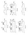
- FIG. 6shows a wafer 500 containing a layer stack of material (e.g., and LED layer stack) deposited on a substrate (e.g., sapphire, compound semiconductor, zinc oxide, silicon carbide, silicon) 502 .
- a layer stack of materiale.g., and LED layer stack
- substratee.g., sapphire, compound semiconductor, zinc oxide, silicon carbide, silicon
- Such wafersare commercially available. Exemplary commercial suppliers include Epistar Corporation, Arima Optoelectronics Corporation and South Epitaxy Corporation.
- a buffer layer 504e.g., a nitride-containing layer, such as a GaN layer, an AlN layer, an AlGaN layer, a superlattice structure as discussed above
- an n-doped semiconductor layere.g., an n-doped Si:GaN
- a current spreading layer 508e.g., an AlGaN/GaN heterojunction or superlattice
- a light-emitting region 510e.g., an InGaN/GaN multi-quantum well region
- a semiconductor layer 512e.g., a p-doped Mg:GaN layer.
- Wafer 500generally has a diameter of at least about two inches (e.g., from about two inches to about 12 inches, from about two inches to about six inches, from about two inches to about four inches, from about two inches to about three inches).
- FIG. 7shows a multi-layer stack 550 including layers 502 , 504 , 506 , 508 , 510 and 512 , as well as layers 520 , 522 , 524 and 526 , which are generally formed of materials capable of being pressure and/or heat bonded as described below.
- layer 520can be a nickel layer (e.g., electron-beam evaporated)
- layer 522can be a silver layer (e.g., electron-beam evaporated)
- layer 524can be a nickel layer (e.g., electron-beam evaporated)
- layer 526can be a gold layer (e.g., electron-beam evaporated).
- layer 520can be a relatively thin layer
- layer 524can be a relatively thick layer.
- Layer 524can act, for example, as diffusion barrier to reduce the diffusion of contaminants (e.g., gold) into layers 520 , 522 and/or 524 itself.
- multi-layer stack 550can be treated to achieve an ohmic contact.
- stack 550can be annealed (e.g., at a temperature of from about 400° C. to about 600° C.) for a period of time (e.g., from about 30 seconds to about 300 seconds) in an appropriate gas environment (e.g., nitrogen, oxygen, air, forming gas).
- an appropriate gas environmente.g., nitrogen, oxygen, air, forming gas
- FIG. 8shows a multi-layer stack 600 that includes a submount (e.g., germanium (such as polycrystalline germanium), silicon (such as polycrystalline silicon), silicon-carbide, copper, copper-tungsten, diamond, nickel-cobalt) 602 having layers 604 , 606 , 608 and 610 deposited thereon.
- Submount 602can be formed, for example, by sputtering or electroforming.
- Layer 604is a contact layer and can be formed, for example, from aluminum (e.g., electron evaporated).
- Layer 606is a diffusion barrier and can be formed, for example, from Ni (e.g. electron evaporated).
- Layer 608can be a gold layer (e.g., electron-beam evaporated), and layer 610 can be a AuSn bonding layer (e.g., thermal evaporated, sputtered) onto layer 608 .
- multi-layer stack 600can be treated to achieve an ohmic contact.
- stack 600can be annealed (e.g., at a temperature of from about 350° C. to about 500° C.) for a period of time (e.g., from about 30 seconds to about 300 seconds) in an appropriate gas environment (e.g., nitrogen, oxygen, air, forming gas).
- an appropriate gas environmente.g., nitrogen, oxygen, air, forming gas.
- FIG. 9shows a multi-layer stack 650 formed by bonding together layers 526 and 610 (e.g., using a solder bond, using a eutectic bond, using a peritectic bond).
- Layers 526 and 610can be bonded, for example, using thermal-mechanical pressing.
- multi-layer stack 650can be put in a press and pressurized (e.g., using a pressure of up to about 5 MPa, up to about 2 MPa) heated (e.g., to a temperature of from about 200° C. to about 400° C.).
- Stack 650can then be cooled (e.g., to room temperature) and removed from the press.
- Substrate 502 and buffer layer 504are then at least partially removed from stack 650 .
- thiscan be achieved using any desired methods.
- substrate 502is removed by exposing stack 650 (e.g., through surface 501 of substrate 502 ) to electromagnetic radiation at an appropriate wavelength to partially decompose layer 504 and/or layer 506 .
- stack 650can be heated during exposure of surface 501 to the electromagnetic radiation (e.g., to reduce strain within stack 650 ).
- Stack 650can be heated, for example, by placing stack 650 on a hot plate and/or by exposing stack 650 to an additional laser source (e.g. a CO2 laser).
- Heating stack 650 during exposure of surface 501 to electromagnetic radiationcan, for example, reduce (e.g., prevent) liquid gallium from re-solidifying. This can reduce the build up of strain within stack 650 which can occur upon the re-solidification of the gallium
- stack 650after exposure to the electromagnetic radiation, residual gallium is present and keeps substrate 502 bonded in stack 650 .
- stack 650can be heated to above the melting temperature of gallium to allow substrate 502 to be removed from the stack.
- stack 650may be exposed to an etchant (e.g., a chemical etchant, such as HCl) to etch the residual gallium and remove substrate 502 .
- etchante.g., a chemical etchant, such as HCl
- Other methods of removing the residual galliummay also be used.
- surface 501is exposed to laser radiation including the absorption wavelength of layer 504 and/or layer 506 (e.g., about 248 nanometers, about 355 nanometers).
- Laser radiation processesare disclosed, for example, in U.S. Pat. Nos. 6,420,242 and 6,071,795, which are hereby incorporated by reference.
- the multi-layer stackcan then heated to above the melting point of gallium, at which point substrate 502 and buffer layer 504 can be removed from the stack by applying a lateral force to substrate 502 (e.g., using a cotton swab).
- multiple portions of surface 501are simultaneously exposed to the electromagnetic radiation.
- multiple portions of surface 501are sequentially exposed to electromagnetic radiation. Combinations of simultaneous and sequential exposure can be used.
- the electromagnetic radiationcan be exposed on surface 501 in the form of a pattern (e.g., a serpentine pattern, a circular pattern, a spiral pattern, a grid, a grating, a triangular pattern, an elementary pattern, a random pattern, a complex pattern, a periodic pattern, a nonperiodic pattern).
- the electromagnetic radiationcan be rastered across one or more portions of surface 501 .
- surface 501is exposed to overlapping fields of electromagnetic radiation.
- the electromagnetic radiationpasses through a mask before reaching surface 501 .
- the electromagnetic radiationcan pass through an optical system that includes a mask (e.g., a high thermal conductivity mask, such as a molybdenum mask, a copper-beryllium mask) before reaching surface 501 .
- the maskis an aperture (e.g., for truncating or shaping the beam).
- the optical systemcan include, for example, at least two lenses having the mask disposed therebetween.
- the maskcan be formed as a pattern of material on surface 501 , with the mask leaving certain portions of surface 501 exposed and some portions of surface 501 unexposed. Such a mask can be formed, for example, via a lithography process.
- the electromagnetic radiationcan be rastered across one or more portions of the mask. Without wishing to be bound by theory, it is believed that reducing at least one dimension of the region on surface 501 exposed to electromagnetic radiation within a given area of surface 501 can limit undesired crack propagation, such as crack propagation into layer 504 , layer 506 or other layers of stack 650 during removal of substrate 502 , while still allowing for crack propagation at the desired layer transfer interface (e.g., the interface between layer 504 and 506 , or the interface between substrate 502 and buffer layer 504 ).
- the desired layer transfer interfacee.g., the interface between layer 504 and 506 , or the interface between substrate 502 and buffer layer 504 .
- a gaseous bubblee.g., a nitrogen bubble
- at least one dimension of the spot or linecan be a maximum of at most about one millimeter (e.g., at most about 500 microns, at most about 100 microns, at most about 25 microns, at most about 10 microns).
- the spot sizeis from about five microns to about one millimeter (e.g., from about five microns to about 100 microns, from about five microns to about 25 microns, from about five microns to about 10 microns).
- stack 650is vibrated while surface 501 is exposed to the electromagnetic radiation. Without wishing to be bound by theory, it is believed that vibrating stack 650 while exposing stack 650 to the electromagnetic radiation can enhance crack propagation along the interface between layer 504 and substrate 502 . Generally, the conditions are selected to limit the propagation of cracks into the layer that is to be transferred (e.g., so that substantially no cracks propagate into the rest of stack 650 ).
- a portion of buffer layer 504typically remains on at least a portion of the surface of layer 506 .
- a residue of material from substrate 502e.g., containing aluminum and/or oxygen
- One or more process stepsare usually used to remove any residue and/or remaining portion of buffer layer 504 present, and to clean the surface of layer 506 (e.g., to remove impurities, such as organics and/or particles).
- the process(es)can be performed using a variety of techniques and/or combinations of techniques. Examples include chemical-mechanical polishing, mechanical polishing, reactive ion etching (e.g., with a substantially chemically etching component), physical etching, and wet etching. Such methods are disclosed, for example, in Ghandhi, S., VLSI Fabrication Principles: Silicon & Gallium Arsenide (1994), which is hereby incorporated by reference.
- the amount of strain in stack 650(e.g., due to the lattice mismatch and/or thermal mismatch between the layers in stack 650 ) can change. For example, if the amount of strain in stack 650 is decreased, the peak output wavelength of region 510 can change (e.g., increase). As another example, if the amount of strain in stack 650 is increased, the peak output wavelength of region 510 can change (e.g., decrease).
- substrate 502 and submount 602are selected so that the coefficient of thermal expansion of submount 602 differs from a coefficient of thermal expansion of substrate 502 by less than about 15% (e.g., less than about 10%, less than about 5%).
- substrate 502 and submount 602are selected so that the thickness of submount 602 is substantially greater than the thickness of substrate 502 .
- semiconductor layers 504 , 506 , 508 , 510 , 512 and submount 602are selected so that the coefficient of thermal expansion of submount 602 differs from a coefficient of thermal expansion of one or more of layers 504 , 506 , 608 , 510 , and 512 by less than about 15% (e.g., less than about 10%, less than about 5%).
- substrate 502 and submount 602can have any desired thickness.
- substrate 502is at most about five millimeters (e.g., at most about three millimeters, at most about one millimeter, about 0.5 millimeter) thick.
- submount 602is at most about 10 millimeters (e.g., at most about five millimeters, at most about one millimeter, about 0.5 millimeter) thick.
- submount 602is thicker than substrate 502 , and, in certain embodiments, substrate 502 is thicker than submount 602 .
- the thickness of layer 506can be reduced to a desired final thickness for use in the light-emitting device. This can be achieved, for example, using a mechanical etching process, alone or in combination with an etching process.
- the surface of layer 506has a relatively high degree of flatness (e.g., a relatively high degree of flatness on the scale of the lithography reticle to be used).
- the surface of layer 506after etching/cleaning the exposed surface of layer 506 , has a flatness of at most about 10 microns per 6.25 square centimeters (e.g., at most about five microns per 6.25 square centimeters, at most about one micron per 6.25 square centimeters). As another example, in certain embodiments, after etching/cleaning the exposed surface of layer 506 , the surface of layer 506 has a flatness of at most about 10 microns per square centimeter (e.g., at most about five microns per square centimeter, at most about one microns per square centimeter).
- the surface of layer 506has an RMS roughness of at most about 50 nanometers (e.g., at most about 25 nanometers, at most about 10 nanometers, at most about five nanometers, at most about one nanometer).
- the exposed surface of layer 506may be too rough and/or insufficiently flat to use nanolithography to form the pattern with sufficient accuracy and/or reproducibility.
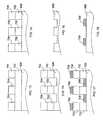
- the nanolithography processmay include depositing a planarization layer on the surface of layer 506 and a lithography layer on the surface of the planarization layer. For example, FIG.
- planarization layer 702is disposed on the surface of layer 506 , and a lithography layer 704 is disposed on the surface of layer 702 , an exposed surface 505 of layer 506 may be relatively rough (e.g., RMS roughness of about 10 nanometers or more) after cleaning/etching layer 506 .
- planarization layer 702is formed of multiple layers (e.g., of the same material) that are sequentially deposited.
- planarization layer 702examples include polymers (e.g., DUV-30J from Brewer Sciences, anti-reflection coatings, high viscosity formable polymers), and examples of materials from which lithography layer 704 can be selected include UV-curable polymers (e.g., low viscosity MonoMatTM available from Molecular Imprints, Inc.). Layers 702 and 704 can be formed using any desired technique, such as, for example, spin coating, vapor deposition, and the like.
- Layer 702can be, for example, at least about 100 nanometers thick (e.g., at least about 500 nanometers thick) and/or at most about five microns thick (e.g., at most about one micron thick).
- Layer 704can be, for example, at least about one nanometer thick (e.g., at least about 10 nanometers thick) and/or at most about one micron thick (e.g., at most about 0.5 micron thick).
- a mold that defines a portion of the desired patternis then pressed into lithography layer and (typically with heating or UV-curing of the mold and/or layer 704 ), and stepped across the surface of layer 704 in a portion-by-portion manner to form indentions in layer 704 ( FIG. 12 ) that correspond to the desired pattern in the surface of layer 506 .
- a single stepcovers the entire wafer (e.g., full wafer nanolithography techniques).
- Layer 704is then etched (e.g., using reactive ion etching, wet etching) to expose portions of the surface of layer 702 corresponding to what were the indented portions of layer 704 ( FIG. 13 ).
- the pattern in layer 704also leaves regions for depositing n-contacts later on in the process flow.
- other techniquese.g., x-ray lithography, deep ultraviolet lithography, extreme ultraviolet lithography, immersion lithography, interference lithography, electron beam lithography, photolithography, microcontact printing, self-assembly techniques
- x-ray lithographydeep ultraviolet lithography
- extreme ultraviolet lithographyextreme ultraviolet lithography
- immersion lithographyimmersion lithography
- interference lithographyelectron beam lithography
- photolithographyphotolithography
- microcontact printingself-assembly techniques
- patterned layer 704is used as a mask to transfer the pattern into the planarization layer 702 (e.g., dry etching, wet etching).
- An example of a dry etching methodis reactive ion etching.
- layers 702 and 704are subsequently used as a mask to transfer the pattern into the surface of layer 506 (e.g., using dry etching, wet etching).
- the layers 702 and 704are removed (e.g., using an oxygen-based reactive ion etch, a wet solvent etch).
- the processcan include, disposing a material 708 (e.g., a metal, such as aluminum, nickel, titanium, tungsten) in the etched portions of layers 702 and 704 (e.g., by evaporation) and on the surface of layer 704 .
- a material 708e.g., a metal, such as aluminum, nickel, titanium, tungsten
- layers 702 and 704are then etched (e.g., using reactive ion etching, wet etching), leaving behind etch-resistant material 708 on the surface of layer 506 , which can serve as a mask for etching the pattern into the surface of layer 506 ( FIG. 19 ).
- etch resistant material 708can then be removed (e.g., using dry etching, wet etching).
- the processcan include, after forming the indents in layer 704 , disposing (e.g., spin coating) an etch resistant material (e.g., a Si-doped polymer) 710 on the surface of layer 704 and in the indents in layer 704 , and material 710 is then etched back (e.g., using dry etching) so that to expose the surface of layer 704 while maintaining the etch-resistant material in the indents in layer 704 ( FIG. 21 ). As shown in FIG.
- an etch resistant materiale.g., a Si-doped polymer
- portions of layers 702 and 704are then etched (e.g., using reactive ion etching, dry etching, wet etching), leaving behind etch-resistant material 710 and the portions of layers 702 and 704 under material 708 , which serve as a mask for etching the pattern into the surface of layer 506 ( FIG. 23 ).
- the remaining portions of layers 702 and 704 , as well as etch resistant material 708can then be removed (e.g., using reactive ion etching, dry etching, wet etching).
- removing layer 708can involve the use of a plasma process (e.g., a fluorine plasma process).
- a layer of wavelength converting materiale.g., a material including one or more phorphors and/or one or more types of quantum dots
- a wavelength converting materialcan conformally coat the patterned surface (coat with substantially no voids present along the bottoms and sidewalls of the openings in the patterned surface).
- a layer of encapsulant materialcan be disposed on the surface of patterned n-doped layer 506 (e.g. by CVD, sputtering, suspension by liquid binder that is subsequently evaporated).
- the encapsulantcan contain one or more phosphor materials and/or one or more types of quantum dots.
- a wavelength converting materialcan be compressed to achieve thickness uniformity less than about 20%, less than about 15%, less than about 10%, less than about 5%, or less than about 2% of the average thickness of the wavelength converting material.
- the wavelength converting material-containing encapsulantcan conformally coat the patterned surface.
- individual LED dicecan be cut from the wafer. Once wafer processing and wafer testing is complete, individual LED dice are separated and prepared for packaging and testing. A sidewall passivation step and/or a pre-separation deep mesa etching step may be used to reduce potential damage to the electrical and/or optical properties of the patterned LED incurred during wafer cutting.
- the individual LEDscan be any size up to the size of the wafer itself, but individual LEDs are typically square or rectangular, with sides having a length between about 0.5 mm to 5 mm.
- standard photolithographyis used to define the location of contact pads on the wafer for energizing the device, and ohmic contacts are evaporated (e.g. using electron beam evaporation) onto the desired locations.
- the packageshould generally be capable of facilitating light collection while also providing mechanical and environmental protection of the die.
- a transparent covercan be packaged on the LED die to protect the patterned surface 506 when an encapsulant is not used.
- the cover slipis attached to supports using a glassy frit that is melted in a furnace. The opposite ends of the supports are connected using a cap weld or an epoxy for example. Supports are typically Ni-plated to facilitate welding to an Au plated surface of the package. It believed that the absence of an encapsulant layer allows higher tolerable power loads per unit area in the patterned surface LED. Degradation of the encapsulant can be a common failure mechanism for standard LEDs and is avoided not using an encapsulant layer.
- the LEDsare cut from a large area flat wafer, their light output per area does not decrease with area. Also, because the cross-section of an individual LEDs cut from a wafer is only slightly larger than the light-emitting surface area of the LED, many individual, and separately addressable LEDs can be packed closely together in an array. If one LED does not function (e.g., due to a large defect), then it does not significant diminish the performance of the array because the individual devices are closely packed.
- the light-emitting devicecan have any desired thickness, and the individual layers within the light-emitting device can have any desired thickness.
- the thicknesses of the layers within multi-layer stackare chosen so as to increase the spatial overlap of the optical modes with light generating region (e.g., active region), to increase the output from light generated in light generating region.
- layer 135can have a thickness of at least about 100 nm (e.g., at least about 200 nm, at least about 300 nm, at least about 400 nm, at least about 500 nm) and/or at most about 10 microns (e.g., at most about five microns, at most about three microns, at most about one micron).
- layer 133has a thickness of at least about 10 nm (e.g., at least about 25 nm, at least about 40 nm) and/or at most about one micron (e.g., at most about 500 nm, at most about 100 nm).
- layer 132has a thickness of at least about 10 nm (e.g., at least about 50 nm, at least about 100 nm) and/or at most about one micron (e.g., at most about 500 nm, at most about 250 nm).
- light-generating region 134has a thickness of at least about 10 nm (e.g., at least about 25 nm, at least about 50 nm, at least about 100 nm) and/or at most about 500 nm (e.g., at most about 250 nm, at most about 150 nm).
- a current spreading layercan be a separate layer from the n-doped layer, in some embodiments, a current spreading layer can be integral with (e.g., a portion of) layer 135 . In such embodiments, the current spreading layer can be a relatively highly n-doped portion of layer 135 or a heterojunction between (e.g. AlGaN/GaN) to form a 2D electron gas.
- any semiconductor materialse.g., III-V semiconductor materials, organic semiconductor materials, silicon
- any semiconductor materialscan be used that can be used in a light-emitting device.
- Examples of other light-generating materialsinclude InGaAsP, AlInGaN, AlGaAs, InGaAlP.
- Organic light-emitting materialsinclude small molecules such as aluminum tris-8-hydroxyquinoline (Alq 3 ) and conjugated polymers such as poly[2-methoxy-5-(2-ethylhexyloxy)-1,4-vinylenephenylene] or MEH-PPV.
- the LEDscan also be small area LEDs (e.g., LEDs smaller than the standard about 300 microns on edge).
- a dielectric function that varies spatially according to a patternhas been described in which the pattern is formed of holes, the pattern can also be formed in other ways.
- a patterncan be formed continuous veins and/or discontinuous veins in the appropriate layer.
- the pattern in varying dielectric functioncan be achieved without using holes or veins.
- materials having different dielectric functionscan be patterned in the appropriate layer. Combinations of such patterns can also be used.
- layer 132has been described as being formed of silver, other materials can also be used.
- layer 126is formed of a material that can reflect at least about 50% of light generated by the light-generating region that impinges on the layer of reflective material, the layer of reflective material being between the support and the multi-layer stack of materials. Examples of such materials include distributed Bragg reflector stacks and various metals and alloys, such as aluminum and aluminum-containing alloys.
- a submountcan be formed of a variety of materials. Examples of materials from which a submount can be formed include copper, copper-tungsten, aluminum nitride, silicon carbide, beryllium-oxide, diamonds, TEC and aluminum.
- a light-emitting devicecan include a separate layer (e.g., disposed between layer 132 and a submount) that serves as a heat sink.
- layer 132may or may not be formed of a material that can serve as a heat sink.
- the varying pattern in dielectric functionhas been described as extending into n-doped layer 135 only (which can substantially reduce the likelihood of surface recombination carrier losses) in addition to making use of the entire light-generating region, in some embodiments, the varying pattern in dielectric function can extend beyond n-doped layer (e.g., into a current spreading layer, light-generating region 134 , and/or p-doped layer 123 ).
- aircan be disposed between surface 138 and a cover slip
- materials other than, or in an addition to, aircan be disposed between surface 138 and the cover slip.
- such materialshave an index of refraction of at least about one and less than about 1.5 (e.g., less than about 1.4, less than about 1.3, less than about 1.2, less than about 1.1).
- examples of such materialsinclude nitrogen, air, or some higher thermal conductivity gas.
- surface 138may or may not be patterned.
- surface 138may be non-pattered but may be roughened (e.g., having randomly distributed features of various sizes and shapes less than ⁇ /5).
- a pre-patterned etch maskcan be laid down on the surface of the n-doped semiconductor layer.
- an etch mask layercan be disposed between the n-doped semiconductor layer and the planarization layer.
- the methodcan include removing at least a portion of the etch mask layer (e.g., to form a pattern in the etch stop layer corresponding to the pattern in the n-doped semiconductor layer).
- surface 138may be patterned and rough (e.g., having randomly distributed features of various sizes and shapes less than ⁇ /5, less than ⁇ /2, less than ⁇ ).
- the sidewalls of openings 139can be rough (e.g., having randomly distributed features of various sizes and shapes less than ⁇ /5, less than ⁇ /2, less than ⁇ ), with or without surface 138 being rough.
- the bottom surface of openings 139can be rough (e.g., having randomly distributed features of various sizes and shapes less than ⁇ /5, less than ⁇ /2, less than ⁇ ).
- Surface 138 , the sidewalls of openings 139 , and/or the bottom surfaces of openings 139can be roughened, for example, by etching (e.g., wet etching, dry etching, reactive ion etching).
- etchinge.g., wet etching, dry etching, reactive ion etching.
- roughening surface 138 and/or the sidewalls of openings 139may increase the probability, with respect to a atomically smooth surface, that a light ray will eventually strike at an angle that less than the critical angle given by Snell's law and will be extracted.
- the submountcan be machined to include spring-like structures. Without wishing to be bound by theory, it is believed that such spring-like structures may reduce cracking during removal of the substrate.
- the submountcan be supported by an acoustically absorbing platform (e.g., a polymer, a metallic foam).
- an acoustically absorbing platforme.g., a polymer, a metallic foam.
- the substrateis treated (e.g., etched, ground, sandblasted) before being removed.
- the substratemay be patterned before it is removed.
- the thickness of the layersis selected so that, before removing the substrate and buffer layers, the neutral mechanical axis of the multi-layer stack is located substantially close (e.g., less than about 500 microns, less than about 100 microns, less than about 10 microns, less than about five microns) to the interface between the p-doped semiconductor layer and a bonding layer.
- portions of the substrateare separately removed (e.g., to reduce the likelihood of cracking).
- a substrateis removed by a process that includes exposing a surface of the substrate to electromagnetic radiation (e.g., laser light)
- electromagnetic radiatione.g., laser light
- other methodscan be used to remove the substrate.
- removal of the substratecan involve etching and/or lapping the substrate.
- the substratecan be etched and/or lapped, and then subsequently exposed to electromagnetic radiation (e.g., laser light).
- the upper surface of the planarization layercan be flattened.
- a flat objectsuch as an optical flat
- a pressurecan be applied (e.g., using a physical weight or press) to assist with the flattening process.
- the substratecan be treated before being removed.
- the substratecan be exposed to one or more processes selected from etching, polishing, grinding and sandblasting.
- treating the substratecan include patterning the substrate.
- treating the substrateincludes depositing an antireflective coating on the substrate.
- Such an antireflective coatingcan, for example, allow relatively large regions of the substrate to be removed when using a substrate removal process that involves exposing the substrate to electromagnetic radiation because the coating can reduce reflection of the electromagnetic radiation.
- a pattern on the surface of the substratecan also be used to achieve an anti-reflection effect.
- a light-emitting devicecan include a layer of a wavelength converting region (e.g., a material including one or more phosphor materials and/or one or more types of quantum dots) coated on surface 138 and/or a cover layer (e.g., a transparent window).
- a light-emitting devicecan include a cover layer (e.g., a transparent window) that has a wavelength converting material (e.g., a material including one or more phosphor materials and/or one or more types of quantum dots) disposed therein.
- surface 138may or may not be patterned.
- the light emitted by the light-generating regionis UV (or violet, or blue) and the wavelength converting material includes a mixture of a red phosphor material (e.g., L 2 O 2 S:Eu 3+ ), a green phosphor material (e.g., ZnS:Cu,Al,Mn), and blue phosphor material (e.g., (Sr,Ca,Ba,Mg) 10 (PO 4 ) 6 Cl:Eu 2+ ).
- a red phosphor materiale.g., L 2 O 2 S:Eu 3+
- a green phosphor materiale.g., ZnS:Cu,Al,Mn
- blue phosphor materiale.g., (Sr,Ca,Ba,Mg) 10 (PO 4 ) 6 Cl:Eu 2+
- a structuree.g., layer, region
- itcan be directly on the structure, or an intervening structure (e.g., layer, region) also may be present.
- a structure that is “directly on” or “in contact with” another structuremeans that no intervening structure is present.
Landscapes
- Led Devices (AREA)
Abstract
Description
Claims (26)
Priority Applications (3)
| Application Number | Priority Date | Filing Date | Title |
|---|---|---|---|
| US12/052,721US8110425B2 (en) | 2007-03-20 | 2008-03-20 | Laser liftoff structure and related methods |
| US13/353,504US8455285B2 (en) | 2007-03-20 | 2012-01-19 | Laser liftoff structure and related methods |
| US13/908,917US8815622B2 (en) | 2007-03-20 | 2013-06-03 | Laser liftoff structure and related methods |
Applications Claiming Priority (2)
| Application Number | Priority Date | Filing Date | Title |
|---|---|---|---|
| US91913607P | 2007-03-20 | 2007-03-20 | |
| US12/052,721US8110425B2 (en) | 2007-03-20 | 2008-03-20 | Laser liftoff structure and related methods |
Related Child Applications (1)
| Application Number | Title | Priority Date | Filing Date |
|---|---|---|---|
| US13/353,504ContinuationUS8455285B2 (en) | 2007-03-20 | 2012-01-19 | Laser liftoff structure and related methods |
Publications (2)
| Publication Number | Publication Date |
|---|---|
| US20080274574A1 US20080274574A1 (en) | 2008-11-06 |
| US8110425B2true US8110425B2 (en) | 2012-02-07 |
Family
ID=39939807
Family Applications (3)
| Application Number | Title | Priority Date | Filing Date |
|---|---|---|---|
| US12/052,721Expired - Fee RelatedUS8110425B2 (en) | 2007-03-20 | 2008-03-20 | Laser liftoff structure and related methods |
| US13/353,504ActiveUS8455285B2 (en) | 2007-03-20 | 2012-01-19 | Laser liftoff structure and related methods |
| US13/908,917ActiveUS8815622B2 (en) | 2007-03-20 | 2013-06-03 | Laser liftoff structure and related methods |
Family Applications After (2)
| Application Number | Title | Priority Date | Filing Date |
|---|---|---|---|
| US13/353,504ActiveUS8455285B2 (en) | 2007-03-20 | 2012-01-19 | Laser liftoff structure and related methods |
| US13/908,917ActiveUS8815622B2 (en) | 2007-03-20 | 2013-06-03 | Laser liftoff structure and related methods |
Country Status (1)
| Country | Link |
|---|---|
| US (3) | US8110425B2 (en) |
Cited By (31)
| Publication number | Priority date | Publication date | Assignee | Title |
|---|---|---|---|---|
| US8455285B2 (en) | 2007-03-20 | 2013-06-04 | Luminus Devices, Inc. | Laser liftoff structure and related methods |
| US20150085389A1 (en)* | 2008-12-15 | 2015-03-26 | Francoise Axel | Method for structuring a non-metal omnidirectional multilayer mirror |
| US9093366B2 (en) | 2012-04-09 | 2015-07-28 | Transphorm Inc. | N-polar III-nitride transistors |
| US20150279945A1 (en)* | 2012-10-26 | 2015-10-01 | Daniel Francis | Semiconductor devices with improved reliability and operating life and methods of manufactuirng the same |
| US9171836B2 (en) | 2011-10-07 | 2015-10-27 | Transphorm Inc. | Method of forming electronic components with increased reliability |
| US20160020120A1 (en)* | 2014-07-20 | 2016-01-21 | X-Celeprint Limited | Apparatus and methods for micro-transfer-printing |
| US9245992B2 (en) | 2013-03-15 | 2016-01-26 | Transphorm Inc. | Carbon doping semiconductor devices |
| US9318593B2 (en) | 2014-07-21 | 2016-04-19 | Transphorm Inc. | Forming enhancement mode III-nitride devices |
| US9443938B2 (en) | 2013-07-19 | 2016-09-13 | Transphorm Inc. | III-nitride transistor including a p-type depleting layer |
| US9536967B2 (en) | 2014-12-16 | 2017-01-03 | Transphorm Inc. | Recessed ohmic contacts in a III-N device |
| US9536966B2 (en) | 2014-12-16 | 2017-01-03 | Transphorm Inc. | Gate structures for III-N devices |
| US9590060B2 (en) | 2013-03-13 | 2017-03-07 | Transphorm Inc. | Enhancement-mode III-nitride devices |
| US20170084769A1 (en)* | 2014-04-04 | 2017-03-23 | The Regents Of The University Of Michigan | Epitaxial lift-off processed gaas thin-film solar cells integrated with non-tracking mini-compound parabolic concentrators |
| US9704821B2 (en) | 2015-08-11 | 2017-07-11 | X-Celeprint Limited | Stamp with structured posts |
| US10103069B2 (en) | 2016-04-01 | 2018-10-16 | X-Celeprint Limited | Pressure-activated electrical interconnection by micro-transfer printing |
| US10181483B2 (en) | 2010-03-29 | 2019-01-15 | X-Celeprint Limited | Laser assisted transfer welding process |
| US10189243B2 (en) | 2011-09-20 | 2019-01-29 | X-Celeprint Limited | Printing transferable components using microstructured elastomeric surfaces with pressure modulated reversible adhesion |
| US10217895B2 (en)* | 2017-06-22 | 2019-02-26 | Epistar Corporation | Method of forming a light-emitting device |
| US10222698B2 (en) | 2016-07-28 | 2019-03-05 | X-Celeprint Limited | Chiplets with wicking posts |
| US10224401B2 (en) | 2016-05-31 | 2019-03-05 | Transphorm Inc. | III-nitride devices including a graded depleting layer |
| US10340187B2 (en) | 2015-03-18 | 2019-07-02 | The Regents Of The University Of Michigan | Strain relief epitaxial lift-off via pre-patterned mesas |
| US10468363B2 (en) | 2015-08-10 | 2019-11-05 | X-Celeprint Limited | Chiplets with connection posts |
| US10658998B2 (en) | 2013-07-31 | 2020-05-19 | Oepic Semiconductors, Inc. | Piezoelectric film transfer for acoustic resonators and filters |
| US10748793B1 (en) | 2019-02-13 | 2020-08-18 | X Display Company Technology Limited | Printing component arrays with different orientations |
| US11064609B2 (en) | 2016-08-04 | 2021-07-13 | X Display Company Technology Limited | Printable 3D electronic structure |
| US11062936B1 (en) | 2019-12-19 | 2021-07-13 | X Display Company Technology Limited | Transfer stamps with multiple separate pedestals |
| US11322599B2 (en) | 2016-01-15 | 2022-05-03 | Transphorm Technology, Inc. | Enhancement mode III-nitride devices having an Al1-xSixO gate insulator |
| US11508875B2 (en)* | 2017-12-22 | 2022-11-22 | Dowa Electronics Materials Co., Ltd. | Semiconductor light-emitting device and method of manufacturing the same |
| US11515448B2 (en)* | 2018-04-19 | 2022-11-29 | Dowa Electronics Materials Co., Ltd. | Semiconductor light-emitting element and method of manufacturing the same |
| US11563140B2 (en)* | 2018-05-02 | 2023-01-24 | Tiajin Sanan Optoelectornics Co., Ltd. | Light emitting device and production method and use thereof |
| US11637220B1 (en) | 2018-04-19 | 2023-04-25 | Dowa Electronics Materials Co., Ltd. | Semiconductor light-emitting element |
Families Citing this family (64)
| Publication number | Priority date | Publication date | Assignee | Title |
|---|---|---|---|---|
| US8278190B2 (en)* | 2007-05-30 | 2012-10-02 | Luminus Devices, Inc. | Methods of forming light-emitting structures |
| US8415879B2 (en) | 2007-05-31 | 2013-04-09 | Nthdegree Technologies Worldwide Inc | Diode for a printable composition |
| US8809126B2 (en) | 2007-05-31 | 2014-08-19 | Nthdegree Technologies Worldwide Inc | Printable composition of a liquid or gel suspension of diodes |
| US9425357B2 (en) | 2007-05-31 | 2016-08-23 | Nthdegree Technologies Worldwide Inc. | Diode for a printable composition |
| US8674593B2 (en) | 2007-05-31 | 2014-03-18 | Nthdegree Technologies Worldwide Inc | Diode for a printable composition |
| US9018833B2 (en) | 2007-05-31 | 2015-04-28 | Nthdegree Technologies Worldwide Inc | Apparatus with light emitting or absorbing diodes |
| US9534772B2 (en) | 2007-05-31 | 2017-01-03 | Nthdegree Technologies Worldwide Inc | Apparatus with light emitting diodes |
| US9343593B2 (en) | 2007-05-31 | 2016-05-17 | Nthdegree Technologies Worldwide Inc | Printable composition of a liquid or gel suspension of diodes |
| US8846457B2 (en) | 2007-05-31 | 2014-09-30 | Nthdegree Technologies Worldwide Inc | Printable composition of a liquid or gel suspension of diodes |
| US8877101B2 (en) | 2007-05-31 | 2014-11-04 | Nthdegree Technologies Worldwide Inc | Method of manufacturing a light emitting, power generating or other electronic apparatus |
| US9419179B2 (en) | 2007-05-31 | 2016-08-16 | Nthdegree Technologies Worldwide Inc | Diode for a printable composition |
| US8852467B2 (en) | 2007-05-31 | 2014-10-07 | Nthdegree Technologies Worldwide Inc | Method of manufacturing a printable composition of a liquid or gel suspension of diodes |
| US8384630B2 (en) | 2007-05-31 | 2013-02-26 | Nthdegree Technologies Worldwide Inc | Light emitting, photovoltaic or other electronic apparatus and system |
| US7915643B2 (en) | 2007-09-17 | 2011-03-29 | Transphorm Inc. | Enhancement mode gallium nitride power devices |
| US8519438B2 (en) | 2008-04-23 | 2013-08-27 | Transphorm Inc. | Enhancement mode III-N HEMTs |
| US7992332B2 (en) | 2008-05-13 | 2011-08-09 | Nthdegree Technologies Worldwide Inc. | Apparatuses for providing power for illumination of a display object |
| US8127477B2 (en) | 2008-05-13 | 2012-03-06 | Nthdegree Technologies Worldwide Inc | Illuminating display systems |
| KR20100008656A (en)* | 2008-07-16 | 2010-01-26 | 삼성전자주식회사 | Fabricating methods of the light emitting element and the light emitting device, the light emitting element and the light emitting device fabricated by the methods |
| JP4599442B2 (en)* | 2008-08-27 | 2010-12-15 | 株式会社東芝 | Manufacturing method of semiconductor light emitting device |
| US8289065B2 (en) | 2008-09-23 | 2012-10-16 | Transphorm Inc. | Inductive load power switching circuits |
| US7898004B2 (en) | 2008-12-10 | 2011-03-01 | Transphorm Inc. | Semiconductor heterostructure diodes |
| JP5634681B2 (en)* | 2009-03-26 | 2014-12-03 | 住友電工デバイス・イノベーション株式会社 | Semiconductor element |
| US8742459B2 (en) | 2009-05-14 | 2014-06-03 | Transphorm Inc. | High voltage III-nitride semiconductor devices |
| US8390000B2 (en) | 2009-08-28 | 2013-03-05 | Transphorm Inc. | Semiconductor devices with field plates |
| US9293667B2 (en) | 2010-08-19 | 2016-03-22 | Soraa, Inc. | System and method for selected pump LEDs with multiple phosphors |
| US8933644B2 (en) | 2009-09-18 | 2015-01-13 | Soraa, Inc. | LED lamps with improved quality of light |
| US20110186887A1 (en)* | 2009-09-21 | 2011-08-04 | Soraa, Inc. | Reflection Mode Wavelength Conversion Material for Optical Devices Using Non-Polar or Semipolar Gallium Containing Materials |
| US8389977B2 (en) | 2009-12-10 | 2013-03-05 | Transphorm Inc. | Reverse side engineered III-nitride devices |
| US8740413B1 (en) | 2010-02-03 | 2014-06-03 | Soraa, Inc. | System and method for providing color light sources in proximity to predetermined wavelength conversion structures |
| US10147850B1 (en) | 2010-02-03 | 2018-12-04 | Soraa, Inc. | System and method for providing color light sources in proximity to predetermined wavelength conversion structures |
| US8905588B2 (en) | 2010-02-03 | 2014-12-09 | Sorra, Inc. | System and method for providing color light sources in proximity to predetermined wavelength conversion structures |
| KR20130117766A (en)* | 2010-09-01 | 2013-10-28 | 엔티에이치 디그리 테크놀로지스 월드와이드 인코포레이티드 | Diodes, printable compositions of a liquid or gel suspension of diodes or other two-terminal integrated circuits, and methods of making same |
| CN103594461B (en)* | 2010-09-01 | 2016-10-05 | 无限科技全球公司 | Printed constituent of diode, diode or the liquid of other two ends integrated circuits or soliquid and preparation method thereof |
| KR102404843B1 (en)* | 2010-09-01 | 2022-06-07 | 엔티에이치 디그리 테크놀로지스 월드와이드 인코포레이티드 | Light emitting, power generating or other electronic apparatus and method of manufacturing same |
| US8455882B2 (en)* | 2010-10-15 | 2013-06-04 | Cree, Inc. | High efficiency LEDs |
| US8742460B2 (en) | 2010-12-15 | 2014-06-03 | Transphorm Inc. | Transistors with isolation regions |
| US8643062B2 (en) | 2011-02-02 | 2014-02-04 | Transphorm Inc. | III-N device structures and methods |
| US8633468B2 (en) | 2011-02-11 | 2014-01-21 | Sensor Electronic Technology, Inc. | Light emitting device with dislocation bending structure |
| US8772842B2 (en) | 2011-03-04 | 2014-07-08 | Transphorm, Inc. | Semiconductor diodes with low reverse bias currents |
| US8716141B2 (en) | 2011-03-04 | 2014-05-06 | Transphorm Inc. | Electrode configurations for semiconductor devices |
| US8865565B2 (en)* | 2011-08-02 | 2014-10-21 | Kabushiki Kaisha Toshiba | LED having a low defect N-type layer that has grown on a silicon substrate |
| US9064980B2 (en)* | 2011-08-25 | 2015-06-23 | Palo Alto Research Center Incorporated | Devices having removed aluminum nitride sections |
| US8901604B2 (en) | 2011-09-06 | 2014-12-02 | Transphorm Inc. | Semiconductor devices with guard rings |
| US9257547B2 (en) | 2011-09-13 | 2016-02-09 | Transphorm Inc. | III-N device structures having a non-insulating substrate |
| US9165766B2 (en) | 2012-02-03 | 2015-10-20 | Transphorm Inc. | Buffer layer structures suited for III-nitride devices with foreign substrates |
| US9184275B2 (en) | 2012-06-27 | 2015-11-10 | Transphorm Inc. | Semiconductor devices with integrated hole collectors |
| JP5881560B2 (en)* | 2012-08-30 | 2016-03-09 | 株式会社東芝 | Semiconductor light emitting device and manufacturing method thereof |
| CN105164811B (en) | 2013-02-15 | 2018-08-31 | 创世舫电子有限公司 | Electrode of semiconductor devices and forming method thereof |
| KR102108196B1 (en)* | 2013-04-05 | 2020-05-08 | 서울바이오시스 주식회사 | Deep ultraviolet light emitting device separated from growth substrate and method for fabricating the same |
| DE102014105192A1 (en)* | 2014-04-11 | 2015-10-15 | Osram Opto Semiconductors Gmbh | Method for detaching a layer to be detached from a substrate |
| US9373761B2 (en)* | 2014-09-23 | 2016-06-21 | Osram Sylvania Inc. | Patterned thin-film wavelength converter and method of making same |
| US10217914B2 (en) | 2015-05-27 | 2019-02-26 | Samsung Electronics Co., Ltd. | Semiconductor light emitting device |
| US9966260B1 (en)* | 2015-09-25 | 2018-05-08 | Apple Inc. | Surface modification process for laser application |
| US10410883B2 (en)* | 2016-06-01 | 2019-09-10 | Corning Incorporated | Articles and methods of forming vias in substrates |
| US10794679B2 (en) | 2016-06-29 | 2020-10-06 | Corning Incorporated | Method and system for measuring geometric parameters of through holes |
| US10134657B2 (en) | 2016-06-29 | 2018-11-20 | Corning Incorporated | Inorganic wafer having through-holes attached to semiconductor wafer |
| US11078112B2 (en) | 2017-05-25 | 2021-08-03 | Corning Incorporated | Silica-containing substrates with vias having an axially variable sidewall taper and methods for forming the same |
| US10580725B2 (en) | 2017-05-25 | 2020-03-03 | Corning Incorporated | Articles having vias with geometry attributes and methods for fabricating the same |
| US12180108B2 (en) | 2017-12-19 | 2024-12-31 | Corning Incorporated | Methods for etching vias in glass-based articles employing positive charge organic molecules |
| US11554984B2 (en) | 2018-02-22 | 2023-01-17 | Corning Incorporated | Alkali-free borosilicate glasses with low post-HF etch roughness |
| US11152294B2 (en) | 2018-04-09 | 2021-10-19 | Corning Incorporated | Hermetic metallized via with improved reliability |
| WO2020061437A1 (en) | 2018-09-20 | 2020-03-26 | Industrial Technology Research Institute | Copper metallization for through-glass vias on thin glass |
| CN113474311B (en) | 2019-02-21 | 2023-12-29 | 康宁股份有限公司 | Glass or glass ceramic article with copper-metallized through-holes and process for making same |
| JP7267791B2 (en)* | 2019-03-19 | 2023-05-02 | 株式会社Kelk | Thermoelectric module and optical module |
Citations (133)
| Publication number | Priority date | Publication date | Assignee | Title |
|---|---|---|---|---|
| US3293513A (en) | 1962-08-08 | 1966-12-20 | Texas Instruments Inc | Semiconductor radiant diode |
| US3739217A (en) | 1969-06-23 | 1973-06-12 | Bell Telephone Labor Inc | Surface roughening of electroluminescent diodes |
| US3922706A (en) | 1965-07-31 | 1975-11-25 | Telefunken Patent | Transistor having emitter with high circumference-surface area ratio |
| US4864370A (en) | 1987-11-16 | 1989-09-05 | Motorola, Inc. | Electrical contact for an LED |
| US5073041A (en) | 1990-11-13 | 1991-12-17 | Bell Communications Research, Inc. | Integrated assembly comprising vertical cavity surface-emitting laser array with Fresnel microlenses |
| US5126231A (en) | 1990-02-26 | 1992-06-30 | Applied Materials, Inc. | Process for multi-layer photoresist etching with minimal feature undercut and unchanging photoresist load during etch |
| US5132751A (en) | 1990-06-08 | 1992-07-21 | Eastman Kodak Company | Light-emitting diode array with projections |
| US5162878A (en) | 1991-02-20 | 1992-11-10 | Eastman Kodak Company | Light-emitting diode array with projections |
| US5359345A (en) | 1992-08-05 | 1994-10-25 | Cree Research, Inc. | Shuttered and cycled light emitting diode display and method of producing the same |
| US5363009A (en) | 1992-08-10 | 1994-11-08 | Mark Monto | Incandescent light with parallel grooves encompassing a bulbous portion |
| US5376580A (en) | 1993-03-19 | 1994-12-27 | Hewlett-Packard Company | Wafer bonding of light emitting diode layers |
| US5426657A (en) | 1993-03-04 | 1995-06-20 | At&T Corp. | Article comprising a focusing semiconductor laser |
| US5486427A (en) | 1993-09-30 | 1996-01-23 | Minnesota Mining And Manufacturing Company | Patterned array of uniform metal microbeads |
| US5491350A (en) | 1993-06-30 | 1996-02-13 | Hitachi Cable Ltd. | Light emitting diode and process for fabricating the same |
| US5528057A (en) | 1993-05-28 | 1996-06-18 | Omron Corporation | Semiconductor luminous element with light reflection and focusing configuration |
| US5600483A (en) | 1994-05-10 | 1997-02-04 | Massachusetts Institute Of Technology | Three-dimensional periodic dielectric structures having photonic bandgaps |
| US5605488A (en) | 1993-10-28 | 1997-02-25 | Kabushiki Kaisha Toshiba | Polishing apparatus of semiconductor wafer |
| US5631190A (en) | 1994-10-07 | 1997-05-20 | Cree Research, Inc. | Method for producing high efficiency light-emitting diodes and resulting diode structures |
| US5633527A (en) | 1995-02-06 | 1997-05-27 | Sandia Corporation | Unitary lens semiconductor device |
| US5724062A (en) | 1992-08-05 | 1998-03-03 | Cree Research, Inc. | High resolution, high brightness light emitting diode display and method and producing the same |
| US5779924A (en) | 1996-03-22 | 1998-07-14 | Hewlett-Packard Company | Ordered interface texturing for a light emitting device |
| US5793062A (en) | 1995-08-10 | 1998-08-11 | Hewlett-Packard Company | Transparent substrate light emitting diodes with directed light output |
| US5814839A (en) | 1995-02-16 | 1998-09-29 | Sharp Kabushiki Kaisha | Semiconductor light-emitting device having a current adjusting layer and a uneven shape light emitting region, and method for producing same |
| US5834331A (en) | 1996-10-17 | 1998-11-10 | Northwestern University | Method for making III-Nitride laser and detection device |
| US5955749A (en) | 1996-12-02 | 1999-09-21 | Massachusetts Institute Of Technology | Light emitting device utilizing a periodic dielectric structure |
| US6071795A (en)* | 1998-01-23 | 2000-06-06 | The Regents Of The University Of California | Separation of thin films from transparent substrates by selective optical processing |
| US6072628A (en) | 1997-01-29 | 2000-06-06 | Thomson Multimedia S.A. | Optical polarisation device |
| US6091085A (en) | 1998-02-19 | 2000-07-18 | Agilent Technologies, Inc. | GaN LEDs with improved output coupling efficiency |
| US6122103A (en) | 1999-06-22 | 2000-09-19 | Moxtech | Broadband wire grid polarizer for the visible spectrum |
| US6222207B1 (en) | 1999-05-24 | 2001-04-24 | Lumileds Lighting, U.S. Llc | Diffusion barrier for increased mirror reflectivity in reflective solderable contacts on high power LED chip |
| US6265820B1 (en) | 1998-01-29 | 2001-07-24 | Emagin Corporation | Heat removal system for use in organic light emitting diode displays having high brightness |
| US6288840B1 (en) | 1999-06-22 | 2001-09-11 | Moxtek | Imbedded wire grid polarizer for the visible spectrum |
| US6287882B1 (en) | 1999-10-04 | 2001-09-11 | Visual Photonics Epitaxy Co., Ltd. | Light emitting diode with a metal-coated reflective permanent substrate and the method for manufacturing the same |
| US6303405B1 (en) | 1998-09-25 | 2001-10-16 | Kabushiki Kaisha Toshiba | Semiconductor light emitting element, and its manufacturing method |
| US6307218B1 (en) | 1998-11-20 | 2001-10-23 | Lumileds Lighting, U.S., Llc | Electrode structures for light emitting devices |
| US6335548B1 (en) | 1999-03-15 | 2002-01-01 | Gentex Corporation | Semiconductor radiation emitter package |
| US6340824B1 (en) | 1997-09-01 | 2002-01-22 | Kabushiki Kaisha Toshiba | Semiconductor light emitting device including a fluorescent material |
| US6388264B1 (en) | 1997-03-28 | 2002-05-14 | Benedict G Pace | Optocoupler package being hermetically sealed |
| US6403985B1 (en) | 1991-01-18 | 2002-06-11 | Kopin Corporation | Method of making light emitting diode displays |
| US6410348B1 (en) | 2000-07-20 | 2002-06-25 | United Epitaxxy Company, Ltd. | Interface texturing for light-emitting device |
| US6410942B1 (en) | 1999-12-03 | 2002-06-25 | Cree Lighting Company | Enhanced light extraction through the use of micro-LED arrays |
| US20020096994A1 (en) | 2000-07-18 | 2002-07-25 | Toshiaki Iwafuchi | Image display unit and method of producing image display unit |
| US6426515B2 (en) | 2000-04-21 | 2002-07-30 | Fujitsu Limited | Semiconductor light-emitting device |
| US20020110172A1 (en) | 2000-06-02 | 2002-08-15 | Ghulam Hasnain | Efficiency GaN-based light emitting devices |
| US20020115265A1 (en) | 2000-12-14 | 2002-08-22 | Toshiaki Iwafuchi | Method of transferring a device, a method of producing a device holding substrate, and a device holding substrate |
| US6448102B1 (en)* | 1998-12-30 | 2002-09-10 | Xerox Corporation | Method for nitride based laser diode with growth substrate removed |
| US6465808B2 (en) | 2000-11-24 | 2002-10-15 | Highlink Technology Corporation | Method and structure for forming an electrode on a light emitting device |
| US6468824B2 (en) | 2001-03-22 | 2002-10-22 | Uni Light Technology Inc. | Method for forming a semiconductor device having a metallic substrate |
| US6469324B1 (en) | 1999-05-25 | 2002-10-22 | Tien Yang Wang | Semiconductor light-emitting device and method for manufacturing the same |
| US20020164839A1 (en) | 2000-03-22 | 2002-11-07 | Ziptronix | Three dimensional device integration method and integrated device |
| US6504180B1 (en) | 1998-07-28 | 2003-01-07 | Imec Vzw And Vrije Universiteit | Method of manufacturing surface textured high-efficiency radiating devices and devices obtained therefrom |
| US6517995B1 (en) | 1999-09-14 | 2003-02-11 | Massachusetts Institute Of Technology | Fabrication of finely featured devices by liquid embossing |
| US20030032209A1 (en) | 2001-08-13 | 2003-02-13 | Jang-Hun Yeh | Methods of fabricating optoelectronic IC modules |
| US6522063B2 (en) | 2001-03-28 | 2003-02-18 | Epitech Corporation | Light emitting diode |
| US6534798B1 (en) | 1999-09-08 | 2003-03-18 | California Institute Of Technology | Surface plasmon enhanced light emitting diode and method of operation for the same |
| US6559075B1 (en)* | 1996-10-01 | 2003-05-06 | Siemens Aktiengesellschaft | Method of separating two layers of material from one another and electronic components produced using this process |
| US6562701B2 (en)* | 2001-03-23 | 2003-05-13 | Matsushita Electric Industrial Co., Ltd. | Method of manufacturing nitride semiconductor substrate |
| US6573537B1 (en) | 1999-12-22 | 2003-06-03 | Lumileds Lighting, U.S., Llc | Highly reflective ohmic contacts to III-nitride flip-chip LEDs |
| US6574383B1 (en) | 2001-04-30 | 2003-06-03 | Massachusetts Institute Of Technology | Input light coupler using a pattern of dielectric contrast distributed in at least two dimensions |
| US20030143772A1 (en) | 2002-01-30 | 2003-07-31 | United Epitaxy Co., Ltd. | High efficiency light emitting diode and method of making the same |
| US20030141563A1 (en) | 2002-01-28 | 2003-07-31 | Bily Wang | Light emitting diode package with fluorescent cover |
| US20030141507A1 (en) | 2002-01-28 | 2003-07-31 | Krames Michael R. | LED efficiency using photonic crystal structure |
| US6614056B1 (en) | 1999-12-01 | 2003-09-02 | Cree Lighting Company | Scalable led with improved current spreading structures |
| US20030164679A1 (en) | 2002-02-27 | 2003-09-04 | Takafumi Hamano | Organic electroluminescence element and image forming apparatus or portable terminal unit using thereof |
| US6627521B2 (en) | 1999-12-21 | 2003-09-30 | Kabushiki Kaisha Toshiba | Semiconductor light emitting element and manufacturing method thereof |
| US6642618B2 (en) | 2000-12-21 | 2003-11-04 | Lumileds Lighting U.S., Llc | Light-emitting device and production thereof |
| US20030209714A1 (en) | 2000-10-12 | 2003-11-13 | General Electric Company | Solid state lighting device with reduced form factor including led with directional emission and package with microoptics |
| US6649437B1 (en) | 2002-08-20 | 2003-11-18 | United Epitaxy Company, Ltd. | Method of manufacturing high-power light emitting diodes |
| US6657236B1 (en) | 1999-12-03 | 2003-12-02 | Cree Lighting Company | Enhanced light extraction in LEDs through the use of internal and external optical elements |
| US20030222263A1 (en) | 2002-06-04 | 2003-12-04 | Kopin Corporation | High-efficiency light-emitting diodes |
| US6661028B2 (en) | 2000-08-01 | 2003-12-09 | United Epitaxy Company, Ltd. | Interface texturing for light-emitting device |
| US6677173B2 (en) | 2000-03-28 | 2004-01-13 | Pioneer Corporation | Method of manufacturing a nitride semiconductor laser with a plated auxiliary metal substrate |
| US6690268B2 (en) | 2000-03-02 | 2004-02-10 | Donnelly Corporation | Video mirror systems incorporating an accessory module |
| US20040027062A1 (en) | 2001-01-16 | 2004-02-12 | General Electric Company | Organic electroluminescent device with a ceramic output coupler and method of making the same |
| US20040033638A1 (en) | 2000-10-17 | 2004-02-19 | Stefan Bader | Method for fabricating a semiconductor component based on GaN |
| US20040043524A1 (en) | 2002-08-28 | 2004-03-04 | Arima Optoelectronics Corp. | Method for fabricating light emitting diode with transparent substrate |
| US6711192B1 (en) | 1999-05-10 | 2004-03-23 | Pioneer Corporation | Nitride semiconductor laser and method of fabricating the same |
| US6740906B2 (en) | 2001-07-23 | 2004-05-25 | Cree, Inc. | Light emitting diodes including modifications for submount bonding |
| US6742907B2 (en) | 1996-09-24 | 2004-06-01 | Seiko Epson Corporation | Illumination device and display device using it |
| US20040110856A1 (en) | 2002-12-04 | 2004-06-10 | Young Jung Gun | Polymer solution for nanoimprint lithography to reduce imprint temperature and pressure |
| US20040130263A1 (en) | 2003-01-02 | 2004-07-08 | Ray-Hua Horng | High brightness led and method for producing the same |
| US6762069B2 (en) | 2002-11-19 | 2004-07-13 | United Epitaxy Company, Ltd. | Method for manufacturing light-emitting element on non-transparent substrate |
| US20040144985A1 (en) | 2001-06-25 | 2004-07-29 | Zhibo Zhang | Optoelectronic devices having arrays of quantum-dot compound semiconductor superlattices therein |
| US6778746B2 (en) | 1997-05-16 | 2004-08-17 | Btg International Limited | Optical devices and methods of fabrication thereof |
| US6784463B2 (en) | 1997-06-03 | 2004-08-31 | Lumileds Lighting U.S., Llc | III-Phospide and III-Arsenide flip chip light-emitting devices |
| US6784027B2 (en) | 2001-11-30 | 2004-08-31 | Osram Opto Semiconductors Gmbh | Light-emitting semiconductor component |
| US6791117B2 (en) | 2002-01-15 | 2004-09-14 | Kabushiki Kaisha Toshiba | Semiconductor light emission device and manufacturing method thereof |
| US6791259B1 (en) | 1998-11-30 | 2004-09-14 | General Electric Company | Solid state illumination system containing a light emitting diode, a light scattering material and a luminescent material |
| US6791119B2 (en) | 2001-02-01 | 2004-09-14 | Cree, Inc. | Light emitting diodes including modifications for light extraction |
| US6794684B2 (en) | 2001-02-01 | 2004-09-21 | Cree, Inc. | Reflective ohmic contacts for silicon carbide including a layer consisting essentially of nickel, methods of fabricating same, and light emitting devices including the same |
| US20040182914A1 (en) | 2003-03-19 | 2004-09-23 | Emcore Corporation | Flip-chip light emitting diode with a thermally stable multiple layer reflective p-type contact |
| US6800500B2 (en) | 1999-02-05 | 2004-10-05 | Lumileds Lighting U.S., Llc | III-nitride light emitting devices fabricated by substrate removal |
| US6812503B2 (en) | 2001-11-29 | 2004-11-02 | Highlink Technology Corporation | Light-emitting device with improved reliability |
| US6818531B1 (en) | 2003-06-03 | 2004-11-16 | Samsung Electro-Mechanics Co., Ltd. | Method for manufacturing vertical GaN light emitting diodes |
| US6825502B2 (en) | 2000-06-30 | 2004-11-30 | Kabushiki Kaisha Toshiba | Light emitting element, method of manufacturing the same, and semiconductor device having light emitting element |
| US6828724B2 (en) | 2000-05-17 | 2004-12-07 | Cambridge Display Technology Limited | Light-emitting devices |
| US6828597B2 (en) | 2001-09-28 | 2004-12-07 | Osram Opto Semiconductors Gmbh | Radiation-emitting semiconductor component |
| US6831302B2 (en) | 2003-04-15 | 2004-12-14 | Luminus Devices, Inc. | Light emitting devices with improved extraction efficiency |
| US20040259279A1 (en) | 2003-04-15 | 2004-12-23 | Erchak Alexei A. | Light emitting device methods |
| US6847057B1 (en) | 2003-08-01 | 2005-01-25 | Lumileds Lighting U.S., Llc | Semiconductor light emitting devices |
| US6849558B2 (en) | 2002-05-22 | 2005-02-01 | The Board Of Trustees Of The Leland Stanford Junior University | Replication and transfer of microstructures and nanostructures |
| US20050042845A1 (en) | 2003-07-14 | 2005-02-24 | Wolfram Urbanek | Methods of processing of gallium nitride |
| US20050051787A1 (en) | 2003-04-15 | 2005-03-10 | Luminus Devices, Inc., A Delaware Corporation | Light emitting devices |
| US6872635B2 (en) | 2001-04-11 | 2005-03-29 | Sony Corporation | Device transferring method, and device arraying method and image display unit fabricating method using the same |
| US6878969B2 (en) | 2002-07-29 | 2005-04-12 | Matsushita Electric Works, Ltd. | Light emitting device |
| US20050082545A1 (en) | 2003-10-21 | 2005-04-21 | Wierer Jonathan J.Jr. | Photonic crystal light emitting device |
| US6891203B2 (en) | 2001-01-10 | 2005-05-10 | Toyoda Gosei Co., Ltd. | Light emitting device |
| US20050112886A1 (en) | 2001-12-28 | 2005-05-26 | Kabushiki Kaisha Toshiba | Light-emitting device and method for manufacturing the same |
| US6900587B2 (en) | 2001-06-28 | 2005-05-31 | Toyoda Gosei Co., Ltd. | Light-emitting diode |
| US20050127375A1 (en) | 2003-12-12 | 2005-06-16 | Erchak Alexei A. | Optical display systems and methods |
| US6924163B2 (en) | 1998-12-24 | 2005-08-02 | Kabushiki Kaisha Toshiba | Semiconductor light emitting device and its manufacturing method |
| US20050191419A1 (en) | 2003-04-11 | 2005-09-01 | Helt James M. | Fabrication of nanostructures |
| US6943379B2 (en) | 2002-04-04 | 2005-09-13 | Toyoda Gosei Co., Ltd. | Light emitting diode |
| US6946683B2 (en) | 2002-01-28 | 2005-09-20 | Nichia Corporation | Opposed terminal structure having a nitride semiconductor element |
| US20050205883A1 (en) | 2004-03-19 | 2005-09-22 | Wierer Jonathan J Jr | Photonic crystal light emitting device |
| US6958494B2 (en) | 2003-08-14 | 2005-10-25 | Dicon Fiberoptics, Inc. | Light emitting diodes with current spreading layer |
| US20060073621A1 (en)* | 2004-10-01 | 2006-04-06 | Palo Alto Research Center Incorporated | Group III-nitride based HEMT device with insulating GaN/AlGaN buffer layer |
| US7074631B2 (en) | 2003-04-15 | 2006-07-11 | Luminus Devices, Inc. | Light emitting device methods |
| US7084434B2 (en) | 2003-04-15 | 2006-08-01 | Luminus Devices, Inc. | Uniform color phosphor-coated light-emitting diode |
| US7083993B2 (en) | 2003-04-15 | 2006-08-01 | Luminus Devices, Inc. | Methods of making multi-layer light emitting devices |
| US7098589B2 (en) | 2003-04-15 | 2006-08-29 | Luminus Devices, Inc. | Light emitting devices with high light collimation |
| US7105861B2 (en) | 2003-04-15 | 2006-09-12 | Luminus Devices, Inc. | Electronic device contact structures |
| US20060225643A1 (en)* | 2005-03-28 | 2006-10-12 | Showa Denko K.K. | AlGaN substrate and production method thereof |
| US7153715B2 (en)* | 2001-11-13 | 2006-12-26 | Matsushita Electric Industrial Co., Ltd. | Semiconductor device and method for fabricating the same |
| US7166871B2 (en) | 2003-04-15 | 2007-01-23 | Luminus Devices, Inc. | Light emitting systems |
| US7262550B2 (en) | 2003-04-15 | 2007-08-28 | Luminus Devices, Inc. | Light emitting diode utilizing a physical pattern |
| US7274043B2 (en) | 2003-04-15 | 2007-09-25 | Luminus Devices, Inc. | Light emitting diode systems |
| US7341880B2 (en) | 2003-09-17 | 2008-03-11 | Luminus Devices, Inc. | Light emitting device processes |
| US7344903B2 (en) | 2003-09-17 | 2008-03-18 | Luminus Devices, Inc. | Light emitting device processes |
| US7368309B2 (en)* | 2002-08-19 | 2008-05-06 | Lg Innotek Co., Ltd. | Nitride semiconductor and fabrication method thereof |
| US7501299B2 (en)* | 2005-11-14 | 2009-03-10 | Palo Alto Research Center Incorporated | Method for controlling the structure and surface qualities of a thin film and product produced thereby |
| US7521854B2 (en) | 2003-04-15 | 2009-04-21 | Luminus Devices, Inc. | Patterned light emitting devices and extraction efficiencies related to the same |
| US7559075B2 (en)* | 2004-07-20 | 2009-07-07 | Funai Electric Co., Ltd. | Digital television broadcast signal receiver |
Family Cites Families (1)
| Publication number | Priority date | Publication date | Assignee | Title |
|---|---|---|---|---|
| US8110425B2 (en) | 2007-03-20 | 2012-02-07 | Luminus Devices, Inc. | Laser liftoff structure and related methods |
- 2008
- 2008-03-20USUS12/052,721patent/US8110425B2/ennot_activeExpired - Fee Related
- 2012
- 2012-01-19USUS13/353,504patent/US8455285B2/enactiveActive
- 2013
- 2013-06-03USUS13/908,917patent/US8815622B2/enactiveActive
Patent Citations (140)
| Publication number | Priority date | Publication date | Assignee | Title |
|---|---|---|---|---|
| US3293513A (en) | 1962-08-08 | 1966-12-20 | Texas Instruments Inc | Semiconductor radiant diode |
| US3922706A (en) | 1965-07-31 | 1975-11-25 | Telefunken Patent | Transistor having emitter with high circumference-surface area ratio |
| US3739217A (en) | 1969-06-23 | 1973-06-12 | Bell Telephone Labor Inc | Surface roughening of electroluminescent diodes |
| US4864370A (en) | 1987-11-16 | 1989-09-05 | Motorola, Inc. | Electrical contact for an LED |
| US5126231A (en) | 1990-02-26 | 1992-06-30 | Applied Materials, Inc. | Process for multi-layer photoresist etching with minimal feature undercut and unchanging photoresist load during etch |
| US5132751A (en) | 1990-06-08 | 1992-07-21 | Eastman Kodak Company | Light-emitting diode array with projections |
| US5073041A (en) | 1990-11-13 | 1991-12-17 | Bell Communications Research, Inc. | Integrated assembly comprising vertical cavity surface-emitting laser array with Fresnel microlenses |
| US6403985B1 (en) | 1991-01-18 | 2002-06-11 | Kopin Corporation | Method of making light emitting diode displays |
| US5162878A (en) | 1991-02-20 | 1992-11-10 | Eastman Kodak Company | Light-emitting diode array with projections |
| US5359345A (en) | 1992-08-05 | 1994-10-25 | Cree Research, Inc. | Shuttered and cycled light emitting diode display and method of producing the same |
| US5724062A (en) | 1992-08-05 | 1998-03-03 | Cree Research, Inc. | High resolution, high brightness light emitting diode display and method and producing the same |
| US5363009A (en) | 1992-08-10 | 1994-11-08 | Mark Monto | Incandescent light with parallel grooves encompassing a bulbous portion |
| US5426657A (en) | 1993-03-04 | 1995-06-20 | At&T Corp. | Article comprising a focusing semiconductor laser |
| US5376580A (en) | 1993-03-19 | 1994-12-27 | Hewlett-Packard Company | Wafer bonding of light emitting diode layers |
| US5528057A (en) | 1993-05-28 | 1996-06-18 | Omron Corporation | Semiconductor luminous element with light reflection and focusing configuration |
| US5491350A (en) | 1993-06-30 | 1996-02-13 | Hitachi Cable Ltd. | Light emitting diode and process for fabricating the same |
| US5486427A (en) | 1993-09-30 | 1996-01-23 | Minnesota Mining And Manufacturing Company | Patterned array of uniform metal microbeads |
| US5605488A (en) | 1993-10-28 | 1997-02-25 | Kabushiki Kaisha Toshiba | Polishing apparatus of semiconductor wafer |
| US5600483A (en) | 1994-05-10 | 1997-02-04 | Massachusetts Institute Of Technology | Three-dimensional periodic dielectric structures having photonic bandgaps |
| US5631190A (en) | 1994-10-07 | 1997-05-20 | Cree Research, Inc. | Method for producing high efficiency light-emitting diodes and resulting diode structures |
| US5633527A (en) | 1995-02-06 | 1997-05-27 | Sandia Corporation | Unitary lens semiconductor device |
| US5814839A (en) | 1995-02-16 | 1998-09-29 | Sharp Kabushiki Kaisha | Semiconductor light-emitting device having a current adjusting layer and a uneven shape light emitting region, and method for producing same |
| US5793062A (en) | 1995-08-10 | 1998-08-11 | Hewlett-Packard Company | Transparent substrate light emitting diodes with directed light output |
| US5779924A (en) | 1996-03-22 | 1998-07-14 | Hewlett-Packard Company | Ordered interface texturing for a light emitting device |
| US6742907B2 (en) | 1996-09-24 | 2004-06-01 | Seiko Epson Corporation | Illumination device and display device using it |
| US6559075B1 (en)* | 1996-10-01 | 2003-05-06 | Siemens Aktiengesellschaft | Method of separating two layers of material from one another and electronic components produced using this process |
| US5834331A (en) | 1996-10-17 | 1998-11-10 | Northwestern University | Method for making III-Nitride laser and detection device |
| US5955749A (en) | 1996-12-02 | 1999-09-21 | Massachusetts Institute Of Technology | Light emitting device utilizing a periodic dielectric structure |
| US6072628A (en) | 1997-01-29 | 2000-06-06 | Thomson Multimedia S.A. | Optical polarisation device |
| US6388264B1 (en) | 1997-03-28 | 2002-05-14 | Benedict G Pace | Optocoupler package being hermetically sealed |
| US6778746B2 (en) | 1997-05-16 | 2004-08-17 | Btg International Limited | Optical devices and methods of fabrication thereof |
| US6784463B2 (en) | 1997-06-03 | 2004-08-31 | Lumileds Lighting U.S., Llc | III-Phospide and III-Arsenide flip chip light-emitting devices |
| US6340824B1 (en) | 1997-09-01 | 2002-01-22 | Kabushiki Kaisha Toshiba | Semiconductor light emitting device including a fluorescent material |
| US6071795A (en)* | 1998-01-23 | 2000-06-06 | The Regents Of The University Of California | Separation of thin films from transparent substrates by selective optical processing |
| US6420242B1 (en) | 1998-01-23 | 2002-07-16 | The Regents Of The University Of California | Separation of thin films from transparent substrates by selective optical processing |
| US6265820B1 (en) | 1998-01-29 | 2001-07-24 | Emagin Corporation | Heat removal system for use in organic light emitting diode displays having high brightness |
| US6091085A (en) | 1998-02-19 | 2000-07-18 | Agilent Technologies, Inc. | GaN LEDs with improved output coupling efficiency |
| US6504180B1 (en) | 1998-07-28 | 2003-01-07 | Imec Vzw And Vrije Universiteit | Method of manufacturing surface textured high-efficiency radiating devices and devices obtained therefrom |
| US6303405B1 (en) | 1998-09-25 | 2001-10-16 | Kabushiki Kaisha Toshiba | Semiconductor light emitting element, and its manufacturing method |
| US6307218B1 (en) | 1998-11-20 | 2001-10-23 | Lumileds Lighting, U.S., Llc | Electrode structures for light emitting devices |
| US6791259B1 (en) | 1998-11-30 | 2004-09-14 | General Electric Company | Solid state illumination system containing a light emitting diode, a light scattering material and a luminescent material |
| US6924163B2 (en) | 1998-12-24 | 2005-08-02 | Kabushiki Kaisha Toshiba | Semiconductor light emitting device and its manufacturing method |
| US6448102B1 (en)* | 1998-12-30 | 2002-09-10 | Xerox Corporation | Method for nitride based laser diode with growth substrate removed |
| US6800500B2 (en) | 1999-02-05 | 2004-10-05 | Lumileds Lighting U.S., Llc | III-nitride light emitting devices fabricated by substrate removal |
| US6335548B1 (en) | 1999-03-15 | 2002-01-01 | Gentex Corporation | Semiconductor radiation emitter package |
| US6711192B1 (en) | 1999-05-10 | 2004-03-23 | Pioneer Corporation | Nitride semiconductor laser and method of fabricating the same |
| US6222207B1 (en) | 1999-05-24 | 2001-04-24 | Lumileds Lighting, U.S. Llc | Diffusion barrier for increased mirror reflectivity in reflective solderable contacts on high power LED chip |
| US6593160B2 (en) | 1999-05-24 | 2003-07-15 | Lumileds Lighting, U.S., Llc | Diffusion barrier for increased mirror reflectivity in reflective solderable contacts on high power led chip |
| US6469324B1 (en) | 1999-05-25 | 2002-10-22 | Tien Yang Wang | Semiconductor light-emitting device and method for manufacturing the same |
| US6122103A (en) | 1999-06-22 | 2000-09-19 | Moxtech | Broadband wire grid polarizer for the visible spectrum |
| US6288840B1 (en) | 1999-06-22 | 2001-09-11 | Moxtek | Imbedded wire grid polarizer for the visible spectrum |
| US6534798B1 (en) | 1999-09-08 | 2003-03-18 | California Institute Of Technology | Surface plasmon enhanced light emitting diode and method of operation for the same |
| US6517995B1 (en) | 1999-09-14 | 2003-02-11 | Massachusetts Institute Of Technology | Fabrication of finely featured devices by liquid embossing |
| US6287882B1 (en) | 1999-10-04 | 2001-09-11 | Visual Photonics Epitaxy Co., Ltd. | Light emitting diode with a metal-coated reflective permanent substrate and the method for manufacturing the same |
| US6614056B1 (en) | 1999-12-01 | 2003-09-02 | Cree Lighting Company | Scalable led with improved current spreading structures |
| US6410942B1 (en) | 1999-12-03 | 2002-06-25 | Cree Lighting Company | Enhanced light extraction through the use of micro-LED arrays |
| US6657236B1 (en) | 1999-12-03 | 2003-12-02 | Cree Lighting Company | Enhanced light extraction in LEDs through the use of internal and external optical elements |
| US6627521B2 (en) | 1999-12-21 | 2003-09-30 | Kabushiki Kaisha Toshiba | Semiconductor light emitting element and manufacturing method thereof |
| US6573537B1 (en) | 1999-12-22 | 2003-06-03 | Lumileds Lighting, U.S., Llc | Highly reflective ohmic contacts to III-nitride flip-chip LEDs |
| US6690268B2 (en) | 2000-03-02 | 2004-02-10 | Donnelly Corporation | Video mirror systems incorporating an accessory module |
| US20020164839A1 (en) | 2000-03-22 | 2002-11-07 | Ziptronix | Three dimensional device integration method and integrated device |
| US6677173B2 (en) | 2000-03-28 | 2004-01-13 | Pioneer Corporation | Method of manufacturing a nitride semiconductor laser with a plated auxiliary metal substrate |
| US6426515B2 (en) | 2000-04-21 | 2002-07-30 | Fujitsu Limited | Semiconductor light-emitting device |
| US6828724B2 (en) | 2000-05-17 | 2004-12-07 | Cambridge Display Technology Limited | Light-emitting devices |
| US20020110172A1 (en) | 2000-06-02 | 2002-08-15 | Ghulam Hasnain | Efficiency GaN-based light emitting devices |
| US6825502B2 (en) | 2000-06-30 | 2004-11-30 | Kabushiki Kaisha Toshiba | Light emitting element, method of manufacturing the same, and semiconductor device having light emitting element |
| US6613610B2 (en) | 2000-07-18 | 2003-09-02 | Sony Corporation | Image display unit and method of producing image display unit |
| US20020096994A1 (en) | 2000-07-18 | 2002-07-25 | Toshiaki Iwafuchi | Image display unit and method of producing image display unit |
| US6410348B1 (en) | 2000-07-20 | 2002-06-25 | United Epitaxxy Company, Ltd. | Interface texturing for light-emitting device |
| US6661028B2 (en) | 2000-08-01 | 2003-12-09 | United Epitaxy Company, Ltd. | Interface texturing for light-emitting device |
| US20030209714A1 (en) | 2000-10-12 | 2003-11-13 | General Electric Company | Solid state lighting device with reduced form factor including led with directional emission and package with microoptics |
| US20040033638A1 (en) | 2000-10-17 | 2004-02-19 | Stefan Bader | Method for fabricating a semiconductor component based on GaN |
| US6465808B2 (en) | 2000-11-24 | 2002-10-15 | Highlink Technology Corporation | Method and structure for forming an electrode on a light emitting device |
| US20020115265A1 (en) | 2000-12-14 | 2002-08-22 | Toshiaki Iwafuchi | Method of transferring a device, a method of producing a device holding substrate, and a device holding substrate |
| US6642618B2 (en) | 2000-12-21 | 2003-11-04 | Lumileds Lighting U.S., Llc | Light-emitting device and production thereof |
| US6891203B2 (en) | 2001-01-10 | 2005-05-10 | Toyoda Gosei Co., Ltd. | Light emitting device |
| US20040027062A1 (en) | 2001-01-16 | 2004-02-12 | General Electric Company | Organic electroluminescent device with a ceramic output coupler and method of making the same |
| US6794684B2 (en) | 2001-02-01 | 2004-09-21 | Cree, Inc. | Reflective ohmic contacts for silicon carbide including a layer consisting essentially of nickel, methods of fabricating same, and light emitting devices including the same |
| US6791119B2 (en) | 2001-02-01 | 2004-09-14 | Cree, Inc. | Light emitting diodes including modifications for light extraction |
| US6468824B2 (en) | 2001-03-22 | 2002-10-22 | Uni Light Technology Inc. | Method for forming a semiconductor device having a metallic substrate |
| US6562701B2 (en)* | 2001-03-23 | 2003-05-13 | Matsushita Electric Industrial Co., Ltd. | Method of manufacturing nitride semiconductor substrate |
| US6522063B2 (en) | 2001-03-28 | 2003-02-18 | Epitech Corporation | Light emitting diode |
| US6872635B2 (en) | 2001-04-11 | 2005-03-29 | Sony Corporation | Device transferring method, and device arraying method and image display unit fabricating method using the same |
| US6574383B1 (en) | 2001-04-30 | 2003-06-03 | Massachusetts Institute Of Technology | Input light coupler using a pattern of dielectric contrast distributed in at least two dimensions |
| US20040144985A1 (en) | 2001-06-25 | 2004-07-29 | Zhibo Zhang | Optoelectronic devices having arrays of quantum-dot compound semiconductor superlattices therein |
| US6900587B2 (en) | 2001-06-28 | 2005-05-31 | Toyoda Gosei Co., Ltd. | Light-emitting diode |
| US20050019971A1 (en) | 2001-07-23 | 2005-01-27 | Slater David B. | Methods of fabricating light emitting devices using mesa regions and passivation layers |
| US6740906B2 (en) | 2001-07-23 | 2004-05-25 | Cree, Inc. | Light emitting diodes including modifications for submount bonding |
| US20030032209A1 (en) | 2001-08-13 | 2003-02-13 | Jang-Hun Yeh | Methods of fabricating optoelectronic IC modules |
| US6828597B2 (en) | 2001-09-28 | 2004-12-07 | Osram Opto Semiconductors Gmbh | Radiation-emitting semiconductor component |
| US7153715B2 (en)* | 2001-11-13 | 2006-12-26 | Matsushita Electric Industrial Co., Ltd. | Semiconductor device and method for fabricating the same |
| US6812503B2 (en) | 2001-11-29 | 2004-11-02 | Highlink Technology Corporation | Light-emitting device with improved reliability |
| US6784027B2 (en) | 2001-11-30 | 2004-08-31 | Osram Opto Semiconductors Gmbh | Light-emitting semiconductor component |
| US20050112886A1 (en) | 2001-12-28 | 2005-05-26 | Kabushiki Kaisha Toshiba | Light-emitting device and method for manufacturing the same |
| US6791117B2 (en) | 2002-01-15 | 2004-09-14 | Kabushiki Kaisha Toshiba | Semiconductor light emission device and manufacturing method thereof |
| US6946683B2 (en) | 2002-01-28 | 2005-09-20 | Nichia Corporation | Opposed terminal structure having a nitride semiconductor element |
| US20030141563A1 (en) | 2002-01-28 | 2003-07-31 | Bily Wang | Light emitting diode package with fluorescent cover |
| US20030141507A1 (en) | 2002-01-28 | 2003-07-31 | Krames Michael R. | LED efficiency using photonic crystal structure |
| US20030143772A1 (en) | 2002-01-30 | 2003-07-31 | United Epitaxy Co., Ltd. | High efficiency light emitting diode and method of making the same |
| US20030164679A1 (en) | 2002-02-27 | 2003-09-04 | Takafumi Hamano | Organic electroluminescence element and image forming apparatus or portable terminal unit using thereof |
| US6943379B2 (en) | 2002-04-04 | 2005-09-13 | Toyoda Gosei Co., Ltd. | Light emitting diode |
| US6849558B2 (en) | 2002-05-22 | 2005-02-01 | The Board Of Trustees Of The Leland Stanford Junior University | Replication and transfer of microstructures and nanostructures |
| US20030222263A1 (en) | 2002-06-04 | 2003-12-04 | Kopin Corporation | High-efficiency light-emitting diodes |
| US6878969B2 (en) | 2002-07-29 | 2005-04-12 | Matsushita Electric Works, Ltd. | Light emitting device |
| US7368309B2 (en)* | 2002-08-19 | 2008-05-06 | Lg Innotek Co., Ltd. | Nitride semiconductor and fabrication method thereof |
| US6649437B1 (en) | 2002-08-20 | 2003-11-18 | United Epitaxy Company, Ltd. | Method of manufacturing high-power light emitting diodes |
| US20040043524A1 (en) | 2002-08-28 | 2004-03-04 | Arima Optoelectronics Corp. | Method for fabricating light emitting diode with transparent substrate |
| US6762069B2 (en) | 2002-11-19 | 2004-07-13 | United Epitaxy Company, Ltd. | Method for manufacturing light-emitting element on non-transparent substrate |
| US20040110856A1 (en) | 2002-12-04 | 2004-06-10 | Young Jung Gun | Polymer solution for nanoimprint lithography to reduce imprint temperature and pressure |
| US20040130263A1 (en) | 2003-01-02 | 2004-07-08 | Ray-Hua Horng | High brightness led and method for producing the same |
| US20040182914A1 (en) | 2003-03-19 | 2004-09-23 | Emcore Corporation | Flip-chip light emitting diode with a thermally stable multiple layer reflective p-type contact |
| US20050191419A1 (en) | 2003-04-11 | 2005-09-01 | Helt James M. | Fabrication of nanostructures |
| US20050051787A1 (en) | 2003-04-15 | 2005-03-10 | Luminus Devices, Inc., A Delaware Corporation | Light emitting devices |
| US7262550B2 (en) | 2003-04-15 | 2007-08-28 | Luminus Devices, Inc. | Light emitting diode utilizing a physical pattern |
| US7521854B2 (en) | 2003-04-15 | 2009-04-21 | Luminus Devices, Inc. | Patterned light emitting devices and extraction efficiencies related to the same |
| US7274043B2 (en) | 2003-04-15 | 2007-09-25 | Luminus Devices, Inc. | Light emitting diode systems |
| US20050087757A1 (en) | 2003-04-15 | 2005-04-28 | Luminus Devices, Inc., A Delaware Corporation | Light emitting devices |
| US7211831B2 (en) | 2003-04-15 | 2007-05-01 | Luminus Devices, Inc. | Light emitting device with patterned surfaces |
| US20040259279A1 (en) | 2003-04-15 | 2004-12-23 | Erchak Alexei A. | Light emitting device methods |
| US7166871B2 (en) | 2003-04-15 | 2007-01-23 | Luminus Devices, Inc. | Light emitting systems |
| US6831302B2 (en) | 2003-04-15 | 2004-12-14 | Luminus Devices, Inc. | Light emitting devices with improved extraction efficiency |
| US7105861B2 (en) | 2003-04-15 | 2006-09-12 | Luminus Devices, Inc. | Electronic device contact structures |
| US7074631B2 (en) | 2003-04-15 | 2006-07-11 | Luminus Devices, Inc. | Light emitting device methods |
| US7084434B2 (en) | 2003-04-15 | 2006-08-01 | Luminus Devices, Inc. | Uniform color phosphor-coated light-emitting diode |
| US7083993B2 (en) | 2003-04-15 | 2006-08-01 | Luminus Devices, Inc. | Methods of making multi-layer light emitting devices |
| US7098589B2 (en) | 2003-04-15 | 2006-08-29 | Luminus Devices, Inc. | Light emitting devices with high light collimation |
| US6818531B1 (en) | 2003-06-03 | 2004-11-16 | Samsung Electro-Mechanics Co., Ltd. | Method for manufacturing vertical GaN light emitting diodes |
| US20050042845A1 (en) | 2003-07-14 | 2005-02-24 | Wolfram Urbanek | Methods of processing of gallium nitride |
| US6847057B1 (en) | 2003-08-01 | 2005-01-25 | Lumileds Lighting U.S., Llc | Semiconductor light emitting devices |
| US6958494B2 (en) | 2003-08-14 | 2005-10-25 | Dicon Fiberoptics, Inc. | Light emitting diodes with current spreading layer |
| US7341880B2 (en) | 2003-09-17 | 2008-03-11 | Luminus Devices, Inc. | Light emitting device processes |
| US7344903B2 (en) | 2003-09-17 | 2008-03-18 | Luminus Devices, Inc. | Light emitting device processes |
| US20050082545A1 (en) | 2003-10-21 | 2005-04-21 | Wierer Jonathan J.Jr. | Photonic crystal light emitting device |
| US7450311B2 (en) | 2003-12-12 | 2008-11-11 | Luminus Devices, Inc. | Optical display systems and methods |
| US20050127375A1 (en) | 2003-12-12 | 2005-06-16 | Erchak Alexei A. | Optical display systems and methods |
| US20050205883A1 (en) | 2004-03-19 | 2005-09-22 | Wierer Jonathan J Jr | Photonic crystal light emitting device |
| US7559075B2 (en)* | 2004-07-20 | 2009-07-07 | Funai Electric Co., Ltd. | Digital television broadcast signal receiver |
| US20060073621A1 (en)* | 2004-10-01 | 2006-04-06 | Palo Alto Research Center Incorporated | Group III-nitride based HEMT device with insulating GaN/AlGaN buffer layer |
| US20060225643A1 (en)* | 2005-03-28 | 2006-10-12 | Showa Denko K.K. | AlGaN substrate and production method thereof |
| US7501299B2 (en)* | 2005-11-14 | 2009-03-10 | Palo Alto Research Center Incorporated | Method for controlling the structure and surface qualities of a thin film and product produced thereby |
Cited By (57)
| Publication number | Priority date | Publication date | Assignee | Title |
|---|---|---|---|---|
| US8815622B2 (en) | 2007-03-20 | 2014-08-26 | Luminus Devices, Inc. | Laser liftoff structure and related methods |
| US8455285B2 (en) | 2007-03-20 | 2013-06-04 | Luminus Devices, Inc. | Laser liftoff structure and related methods |
| US20150085389A1 (en)* | 2008-12-15 | 2015-03-26 | Francoise Axel | Method for structuring a non-metal omnidirectional multilayer mirror |
| US9477017B2 (en)* | 2008-12-15 | 2016-10-25 | Francoise Axel | Method for structuring a non-metal omnidirectional multilayer mirror |
| US10181483B2 (en) | 2010-03-29 | 2019-01-15 | X-Celeprint Limited | Laser assisted transfer welding process |
| US10717267B2 (en) | 2011-09-20 | 2020-07-21 | X Display Company Technology Limited | Printing transferable components using microstructured elastomeric surfaces with pressure modulated reversible adhesion |
| US10189243B2 (en) | 2011-09-20 | 2019-01-29 | X-Celeprint Limited | Printing transferable components using microstructured elastomeric surfaces with pressure modulated reversible adhesion |
| US9171836B2 (en) | 2011-10-07 | 2015-10-27 | Transphorm Inc. | Method of forming electronic components with increased reliability |
| US9093366B2 (en) | 2012-04-09 | 2015-07-28 | Transphorm Inc. | N-polar III-nitride transistors |
| US9490324B2 (en) | 2012-04-09 | 2016-11-08 | Transphorm Inc. | N-polar III-nitride transistors |
| US20150279945A1 (en)* | 2012-10-26 | 2015-10-01 | Daniel Francis | Semiconductor devices with improved reliability and operating life and methods of manufactuirng the same |
| US10043898B2 (en) | 2013-03-13 | 2018-08-07 | Transphorm Inc. | Enhancement-mode III-nitride devices |
| US10535763B2 (en) | 2013-03-13 | 2020-01-14 | Transphorm Inc. | Enhancement-mode III-nitride devices |
| US9590060B2 (en) | 2013-03-13 | 2017-03-07 | Transphorm Inc. | Enhancement-mode III-nitride devices |
| US9245992B2 (en) | 2013-03-15 | 2016-01-26 | Transphorm Inc. | Carbon doping semiconductor devices |
| US9245993B2 (en) | 2013-03-15 | 2016-01-26 | Transphorm Inc. | Carbon doping semiconductor devices |
| US9865719B2 (en) | 2013-03-15 | 2018-01-09 | Transphorm Inc. | Carbon doping semiconductor devices |
| US10043896B2 (en) | 2013-07-19 | 2018-08-07 | Transphorm Inc. | III-Nitride transistor including a III-N depleting layer |
| US9443938B2 (en) | 2013-07-19 | 2016-09-13 | Transphorm Inc. | III-nitride transistor including a p-type depleting layer |
| US9842922B2 (en) | 2013-07-19 | 2017-12-12 | Transphorm Inc. | III-nitride transistor including a p-type depleting layer |
| US10658998B2 (en) | 2013-07-31 | 2020-05-19 | Oepic Semiconductors, Inc. | Piezoelectric film transfer for acoustic resonators and filters |
| US20170084769A1 (en)* | 2014-04-04 | 2017-03-23 | The Regents Of The University Of Michigan | Epitaxial lift-off processed gaas thin-film solar cells integrated with non-tracking mini-compound parabolic concentrators |
| US10141465B2 (en)* | 2014-04-04 | 2018-11-27 | The Regents Of The University Of Michigan | Epitaxial lift-off processed GaAs thin-film solar cells integrated with non-tracking mini-compound parabolic concentrators |
| US9434150B2 (en)* | 2014-07-20 | 2016-09-06 | X-Celeprint Limited | Apparatus and methods for micro-transfer-printing |
| US11472171B2 (en) | 2014-07-20 | 2022-10-18 | X Display Company Technology Limited | Apparatus and methods for micro-transfer-printing |
| US10252514B2 (en) | 2014-07-20 | 2019-04-09 | X-Celeprint Limited | Apparatus and methods for micro-transfer-printing |
| US20160020120A1 (en)* | 2014-07-20 | 2016-01-21 | X-Celeprint Limited | Apparatus and methods for micro-transfer-printing |
| US9318593B2 (en) | 2014-07-21 | 2016-04-19 | Transphorm Inc. | Forming enhancement mode III-nitride devices |
| US9935190B2 (en) | 2014-07-21 | 2018-04-03 | Transphorm Inc. | Forming enhancement mode III-nitride devices |
| US9536967B2 (en) | 2014-12-16 | 2017-01-03 | Transphorm Inc. | Recessed ohmic contacts in a III-N device |
| US9536966B2 (en) | 2014-12-16 | 2017-01-03 | Transphorm Inc. | Gate structures for III-N devices |
| US10340187B2 (en) | 2015-03-18 | 2019-07-02 | The Regents Of The University Of Michigan | Strain relief epitaxial lift-off via pre-patterned mesas |
| US10899067B2 (en) | 2015-07-20 | 2021-01-26 | X Display Company Technology Limited | Multi-layer stamp |
| US11552034B2 (en) | 2015-08-10 | 2023-01-10 | X Display Company Technology Limited | Chiplets with connection posts |
| US10468363B2 (en) | 2015-08-10 | 2019-11-05 | X-Celeprint Limited | Chiplets with connection posts |
| US11276657B2 (en) | 2015-08-10 | 2022-03-15 | X Display Company Technology Limited | Chiplets with connection posts |
| US10777521B2 (en) | 2015-08-10 | 2020-09-15 | X Display Company Technology Limited | Printable component structure with electrical contact |
| US9704821B2 (en) | 2015-08-11 | 2017-07-11 | X-Celeprint Limited | Stamp with structured posts |
| US11318663B2 (en) | 2015-10-20 | 2022-05-03 | X Display Company Technology Limited | Multi-layer stamp |
| US11322599B2 (en) | 2016-01-15 | 2022-05-03 | Transphorm Technology, Inc. | Enhancement mode III-nitride devices having an Al1-xSixO gate insulator |
| US10103069B2 (en) | 2016-04-01 | 2018-10-16 | X-Celeprint Limited | Pressure-activated electrical interconnection by micro-transfer printing |
| US10163735B2 (en) | 2016-04-01 | 2018-12-25 | X-Celeprint Limited | Pressure-activated electrical interconnection by micro-transfer printing |
| US11121216B2 (en) | 2016-05-31 | 2021-09-14 | Transphorm Technology, Inc. | III-nitride devices including a graded depleting layer |
| US10629681B2 (en) | 2016-05-31 | 2020-04-21 | Transphorm Technology, Inc. | III-nitride devices including a graded depleting layer |
| US10224401B2 (en) | 2016-05-31 | 2019-03-05 | Transphorm Inc. | III-nitride devices including a graded depleting layer |
| US10222698B2 (en) | 2016-07-28 | 2019-03-05 | X-Celeprint Limited | Chiplets with wicking posts |
| US11064609B2 (en) | 2016-08-04 | 2021-07-13 | X Display Company Technology Limited | Printable 3D electronic structure |
| US10573778B2 (en) | 2017-06-22 | 2020-02-25 | Epistar Corporation | Semiconductor device |
| US10217895B2 (en)* | 2017-06-22 | 2019-02-26 | Epistar Corporation | Method of forming a light-emitting device |
| US11508875B2 (en)* | 2017-12-22 | 2022-11-22 | Dowa Electronics Materials Co., Ltd. | Semiconductor light-emitting device and method of manufacturing the same |
| US11996496B2 (en) | 2017-12-22 | 2024-05-28 | Dowa Electronics Materials Co., Ltd. | Semiconductor light-emitting device |
| US11515448B2 (en)* | 2018-04-19 | 2022-11-29 | Dowa Electronics Materials Co., Ltd. | Semiconductor light-emitting element and method of manufacturing the same |
| US11637220B1 (en) | 2018-04-19 | 2023-04-25 | Dowa Electronics Materials Co., Ltd. | Semiconductor light-emitting element |
| US11563140B2 (en)* | 2018-05-02 | 2023-01-24 | Tiajin Sanan Optoelectornics Co., Ltd. | Light emitting device and production method and use thereof |
| US11973163B2 (en) | 2018-05-02 | 2024-04-30 | Tianjin Sanan Optoelectronics Co., Ltd. | Light emitting device and production method and use thereof |
| US10748793B1 (en) | 2019-02-13 | 2020-08-18 | X Display Company Technology Limited | Printing component arrays with different orientations |
| US11062936B1 (en) | 2019-12-19 | 2021-07-13 | X Display Company Technology Limited | Transfer stamps with multiple separate pedestals |
Also Published As
| Publication number | Publication date |
|---|---|
| US20120115268A1 (en) | 2012-05-10 |
| US8815622B2 (en) | 2014-08-26 |
| US20130337599A1 (en) | 2013-12-19 |
| US8455285B2 (en) | 2013-06-04 |
| US20080274574A1 (en) | 2008-11-06 |
Similar Documents
| Publication | Publication Date | Title |
|---|---|---|
| US8815622B2 (en) | Laser liftoff structure and related methods | |
| US9698306B2 (en) | Large emission area light-emitting devices | |
| US7915679B2 (en) | Light-emitting devices including a nonperiodic pattern | |
| US6831302B2 (en) | Light emitting devices with improved extraction efficiency | |
| US7521854B2 (en) | Patterned light emitting devices and extraction efficiencies related to the same | |
| US7084434B2 (en) | Uniform color phosphor-coated light-emitting diode | |
| US20040206962A1 (en) | Light emitting devices | |
| US20040207323A1 (en) | Light emitting devices |
Legal Events
| Date | Code | Title | Description |
|---|---|---|---|
| AS | Assignment | Owner name:LUMINUS DEVICES, INC., MASSACHUSETTS Free format text:ASSIGNMENT OF ASSIGNORS INTEREST;ASSIGNOR:YUN, FENG;REEL/FRAME:022319/0839 Effective date:20080711 | |
| ZAAA | Notice of allowance and fees due | Free format text:ORIGINAL CODE: NOA | |
| ZAAB | Notice of allowance mailed | Free format text:ORIGINAL CODE: MN/=. | |
| STCF | Information on status: patent grant | Free format text:PATENTED CASE | |
| AS | Assignment | Owner name:LUMINUS DEVICES, INC., MASSACHUSETTS Free format text:ASSIGNMENT OF ASSIGNORS INTEREST;ASSIGNOR:YUN, FENG;REEL/FRAME:031976/0441 Effective date:20080710 | |
| REMI | Maintenance fee reminder mailed | ||
| AS | Assignment | Owner name:EAST WEST BANK, CALIFORNIA Free format text:SECURITY INTEREST;ASSIGNOR:LUMINUS DEVICES, INC.;REEL/FRAME:036869/0355 Effective date:20151008 | |
| FPAY | Fee payment | Year of fee payment:4 | |
| SULP | Surcharge for late payment | ||
| AS | Assignment | Owner name:LUMINUS DEVICES, INC., CALIFORNIA Free format text:RELEASE BY SECURED PARTY;ASSIGNOR:EAST WEST BANK;REEL/FRAME:045020/0103 Effective date:20180108 | |
| FEPP | Fee payment procedure | Free format text:MAINTENANCE FEE REMINDER MAILED (ORIGINAL EVENT CODE: REM.); ENTITY STATUS OF PATENT OWNER: LARGE ENTITY | |
| FEPP | Fee payment procedure | Free format text:7.5 YR SURCHARGE - LATE PMT W/IN 6 MO, LARGE ENTITY (ORIGINAL EVENT CODE: M1555); ENTITY STATUS OF PATENT OWNER: LARGE ENTITY | |
| MAFP | Maintenance fee payment | Free format text:PAYMENT OF MAINTENANCE FEE, 8TH YEAR, LARGE ENTITY (ORIGINAL EVENT CODE: M1552); ENTITY STATUS OF PATENT OWNER: LARGE ENTITY Year of fee payment:8 | |
| FEPP | Fee payment procedure | Free format text:MAINTENANCE FEE REMINDER MAILED (ORIGINAL EVENT CODE: REM.); ENTITY STATUS OF PATENT OWNER: LARGE ENTITY | |
| LAPS | Lapse for failure to pay maintenance fees | Free format text:PATENT EXPIRED FOR FAILURE TO PAY MAINTENANCE FEES (ORIGINAL EVENT CODE: EXP.); ENTITY STATUS OF PATENT OWNER: LARGE ENTITY | |
| STCH | Information on status: patent discontinuation | Free format text:PATENT EXPIRED DUE TO NONPAYMENT OF MAINTENANCE FEES UNDER 37 CFR 1.362 | |
| FP | Lapsed due to failure to pay maintenance fee | Effective date:20240207 |