US8109948B2 - Compression anastomosis device and method - Google Patents
Compression anastomosis device and methodDownload PDFInfo
- Publication number
- US8109948B2 US8109948B2US11/827,691US82769107AUS8109948B2US 8109948 B2US8109948 B2US 8109948B2US 82769107 AUS82769107 AUS 82769107AUS 8109948 B2US8109948 B2US 8109948B2
- Authority
- US
- United States
- Prior art keywords
- tubular structure
- sleeve
- cylindrical sleeve
- rod
- inverting
- Prior art date
- Legal status (The legal status is an assumption and is not a legal conclusion. Google has not performed a legal analysis and makes no representation as to the accuracy of the status listed.)
- Expired - Fee Related, expires
Links
- 238000000034methodMethods0.000titleclaimsdescription23
- 230000003872anastomosisEffects0.000titleclaimsdescription5
- 230000006835compressionEffects0.000titledescription5
- 238000007906compressionMethods0.000titledescription5
- 238000005304joiningMethods0.000claimsabstractdescription7
- 238000001356surgical procedureMethods0.000description9
- 239000000463materialSubstances0.000description6
- 229920000954PolyglycolidePolymers0.000description4
- 239000004633polyglycolic acidSubstances0.000description4
- 229920001577copolymerPolymers0.000description3
- 239000000835fiberSubstances0.000description3
- 238000005520cutting processMethods0.000description2
- 238000003780insertionMethods0.000description2
- 230000037431insertionEffects0.000description2
- 239000004626polylactic acidSubstances0.000description2
- RKDVKSZUMVYZHH-UHFFFAOYSA-N1,4-dioxane-2,5-dioneChemical compoundO=C1COC(=O)CO1RKDVKSZUMVYZHH-UHFFFAOYSA-N0.000description1
- 239000008186active pharmaceutical agentSubstances0.000description1
- 230000017531blood circulationEffects0.000description1
- 210000001124body fluidAnatomy0.000description1
- 238000010276constructionMethods0.000description1
- 238000006073displacement reactionMethods0.000description1
- 150000002148estersChemical class0.000description1
- 230000035876healingEffects0.000description1
- 239000007943implantSubstances0.000description1
- 210000000936intestineAnatomy0.000description1
- 238000004519manufacturing processMethods0.000description1
- 229920000747poly(lactic acid)Polymers0.000description1
- 239000002952polymeric resinSubstances0.000description1
- 238000000926separation methodMethods0.000description1
- 239000000126substanceSubstances0.000description1
- 239000003356suture materialSubstances0.000description1
- 229920003002synthetic resinPolymers0.000description1
Images


Classifications
- A—HUMAN NECESSITIES
- A61—MEDICAL OR VETERINARY SCIENCE; HYGIENE
- A61B—DIAGNOSIS; SURGERY; IDENTIFICATION
- A61B17/00—Surgical instruments, devices or methods
- A61B17/11—Surgical instruments, devices or methods for performing anastomosis; Buttons for anastomosis
- A—HUMAN NECESSITIES
- A61—MEDICAL OR VETERINARY SCIENCE; HYGIENE
- A61B—DIAGNOSIS; SURGERY; IDENTIFICATION
- A61B17/00—Surgical instruments, devices or methods
- A61B17/11—Surgical instruments, devices or methods for performing anastomosis; Buttons for anastomosis
- A61B17/1114—Surgical instruments, devices or methods for performing anastomosis; Buttons for anastomosis of the digestive tract, e.g. bowels or oesophagus
- A—HUMAN NECESSITIES
- A61—MEDICAL OR VETERINARY SCIENCE; HYGIENE
- A61B—DIAGNOSIS; SURGERY; IDENTIFICATION
- A61B17/00—Surgical instruments, devices or methods
- A61B17/11—Surgical instruments, devices or methods for performing anastomosis; Buttons for anastomosis
- A61B2017/1103—Approximator
- A—HUMAN NECESSITIES
- A61—MEDICAL OR VETERINARY SCIENCE; HYGIENE
- A61B—DIAGNOSIS; SURGERY; IDENTIFICATION
- A61B17/00—Surgical instruments, devices or methods
- A61B17/11—Surgical instruments, devices or methods for performing anastomosis; Buttons for anastomosis
- A61B2017/1107—Surgical instruments, devices or methods for performing anastomosis; Buttons for anastomosis for blood vessels
- A—HUMAN NECESSITIES
- A61—MEDICAL OR VETERINARY SCIENCE; HYGIENE
- A61B—DIAGNOSIS; SURGERY; IDENTIFICATION
- A61B17/00—Surgical instruments, devices or methods
- A61B17/11—Surgical instruments, devices or methods for performing anastomosis; Buttons for anastomosis
- A61B17/1114—Surgical instruments, devices or methods for performing anastomosis; Buttons for anastomosis of the digestive tract, e.g. bowels or oesophagus
- A61B2017/1117—Surgical instruments, devices or methods for performing anastomosis; Buttons for anastomosis of the digestive tract, e.g. bowels or oesophagus adapted for discharge after necrotisation, e.g. by evacuation, expulsion or excretion
- A—HUMAN NECESSITIES
- A61—MEDICAL OR VETERINARY SCIENCE; HYGIENE
- A61B—DIAGNOSIS; SURGERY; IDENTIFICATION
- A61B17/00—Surgical instruments, devices or methods
- A61B17/11—Surgical instruments, devices or methods for performing anastomosis; Buttons for anastomosis
- A61B2017/1121—Surgical instruments, devices or methods for performing anastomosis; Buttons for anastomosis adapted for performing tissue or graft eversion
- A—HUMAN NECESSITIES
- A61—MEDICAL OR VETERINARY SCIENCE; HYGIENE
- A61B—DIAGNOSIS; SURGERY; IDENTIFICATION
- A61B17/00—Surgical instruments, devices or methods
- A61B17/11—Surgical instruments, devices or methods for performing anastomosis; Buttons for anastomosis
- A61B2017/1132—End-to-end connections
Definitions
- the present disclosuregenerally relates to devices and methods for joining tubular structures via anastomosis. More particularly, the present disclosure relates to a compression anastomosis devices and methods of their use in surgical procedures.
- Compression anastomotic deviceshave been developed in the past for receiving the free ends of anatomic tubular structures to be anastomosed.
- An example of such an anastomotic devicehas been developed by Tyco Healthcare LP, Norwalk, Conn., and is currently sold under the trademark VALTRAC®.
- This assemblyincludes a pair of ring members, each ring member for securement to the free end of each tubular structure to be anastomosed.
- Each ring memberhas a connecting structure, which mates with the other ring member to connect the ring members to one another.
- any foreign substances used in anastomotic surgeryshould partially or completely disintegrate, bio-absorb and/or bio-resorb once the tubular structures have partially or fully healed, desirably in a relatively short period of time.
- an anastomotic devicefor use in the joining of a first tubular structure and a second tubular structure.
- the anastomotic deviceincludes a cylindrical sleeve configured and dimensioned for placement at least partially within the first tubular structure; an inverting member for facilitating positioning of at least a portion of the second tubular structure around at least a portion of the first tubular structure; and a constricting member supported on the inverting member and movable onto the cylindrical sleeve to constrict at least a portion of the second tubular structure towards at least a portion of the first tubular structure and towards the cylindrical sleeve.
- the cylindrical sleevedefines a bore therethrough. It is envisioned that at least one of the cylindrical sleeve, the constricting member and the inverting member is bio-absorbable.
- the cylindrical sleevemay include an inner diameter and an outer diameter.
- the outer diameter of the cylindrical sleeveis smaller than an inner diameter of the inverting member.
- the constricting membermay be a garter spring, which is configured to exert constrictive forces on at least a portion of the first tubular structure.
- the anastomotic devicemay further include a rod which is configured and adapted for insertion through the first tubular structure and the second tubular structure. A portion of the first tubular structure may be sutured about the rod and a portion of the second tubular structure may also be sutured about the rod.
- the rodincludes a distal end having a dimension which is larger than the inner diameter of the cylindrical sleeve.
- the anastomotic devicefurther includes an ejecting member configured and adapted to move the constricting member from the inverting member to the cylindrical sleeve.
- the anastomotic devicefurther includes an ejecting member which facilitates positioning of the spring at least partially about the first tubular structure and the second tubular structure.
- the cylindrical sleeveincludes a circumferential groove formed in an outer surface thereof for receiving the constricting member therein.
- a method for joining a first tubular structure to a second tubular structureincludes the steps of providing an anastomotic device having a cylindrical sleeve; an inverting member; a constricting member supported on the inverting member and movable onto the cylindrical sleeve; and a rod configured and adapted for insertion through the cylindrical sleeve, the inverting member, the first tubular structure and the second tubular structure.
- the methodfurther includes the steps of positioning the cylindrical sleeve onto a shaft portion of the rod; positioning the cylindrical sleeve, through the second tubular structure, into the first tubular structure; suturing a free end of the first tubular structure to the shaft portion of the rod; suturing a free end of the second tubular structure to the shaft portion of the rod; positioning the inverting member over the shaft portion of the rod and into the second tubular portion; and withdrawing the rod relative to the inverting member to approximate the cylindrical sleeve and the inverting member, such that at least a portion of second tubular structure is at least partially around the free end of the first tubular structure, creating a second tubular structure outer layer and an inner layer.
- the methodfurther includes the step of moving the constricting member from the inverting member to the cylindrical sleeve such that the constricting member is positioned at least partially between the outer layer and the inner layer of the second tubular structure and outside of the first tubular structure, wherein the constricting member at least a portion of the first tubular structure and at least a portion of the second tubular structure towards the cylindrical sleeve.
- the methodmay further include the step of cutting off at least a portion of the free end of the first tubular structure, at least a portion of the free end of the second tubular structure.
- the methodmay further include the step of allowing at least a portion of the first tubular structure and at least a portion of the second tubular structure to become joined with one another.
- the constricting memberis a garter spring.
- the methodmay further include the step of providing an ejecting member configured and adapted to facilitate positioning of the constricting member at least partially between the outer layer and the inner layer of the second tubular structure, and outside of the first tubular structure.
- At least one of the cylindrical sleeve, the inverting member and the constricting memberis bio-absorbable.
- an anastomotic devicefor use in the joining of a first tubular structure and a second tubular structure.
- the anastomotic deviceincludes a cylindrical sleeve configured and dimensioned for placement at least partially within the first tubular structure, the cylindrical sleeve defining a bore therethrough; an inverting member configured and dimensioned for placement at least partially within the second tubular structure, the inverting member defining a bore therethrough which is configured and dimensioned to selectively receive the cylindrical sleeve therein; and a constricting member selectively positionable on the inverting member and movable onto the cylindrical sleeve when the cylindrical sleeve is at least partially positioned within the bore of the inverting member.
- the anastomotic devicemay further include an ejecting member configured and dimensioned to move the constricting member from the ejecting member to the cylindrical sleeve when the cylindrical sleeve is at least partially positioned within the bore of the inverting member.
- the anastomotic devicemay still further include a rod selectively positionable through the bores of the cylindrical sleeve and the inverting member, wherein the rod includes a head portion configured and dimensioned to engage a distal-most end of the cylindrical sleeve and approximate the cylindrical sleeve toward the inverting member upon a proximal displacement of the rod relative to the inverting member.
- At least one of the cylindrical sleeve, the inverting member and the constricting memberis bio-absorbable.
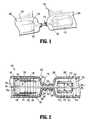
- FIG. 1is a perspective view of an anastomotic device of the present disclosure, illustrated partially within a first tubular structure and partially within a second tubular structure;
- FIG. 2is a longitudinal cross-sectional view of the anastomotic device and tubular structures of FIG. 1 ;
- FIG. 3is a longitudinal cross-sectional view of the anastomotic device and tubular structures of FIGS. 1 and 2 , illustrating the first tubular structure partially positioned within a portion of the second tubular structure;
- FIG. 4is a longitudinal cross-sectional view of the anastomotic device and tubular structures of FIGS. 1-3 , illustrating the first tubular structure partially positioned within the second tubular structure in accordance with the present disclosure;
- FIG. 5is a longitudinal cross-sectional view of the anastomotic device and tubular structures of FIGS. 1-4 , illustrating the purse-stringed portions of each of the first tubular structure and second tubular structure having been cut off;
- FIG. 6is a longitudinal cross-sectional view of the anastomotic device and tubular structures of FIGS. 1-5 , illustrating separation of necrosed rings of tissue from the anastomosed tubular structure.
- distalrefers to that portion which is farthest from the user (generally illustrated on the figures as being towards the right) while the term “proximal” refers to that portion which is closest to the user (generally illustrated on the figures as being towards the left).
- an anastomotic device 100for joining a first tubular structure 200 and a second tubular structure 300 , via anastomotic surgery, is provided.
- anastomotic device 100generally includes a sleeve 110 , an inverting member 120 , and a constricting member, such as a spring, 130 .
- anastomotic device 100further includes an ejecting member 150 and an approximating rod member 160 .
- the sleeve 110is generally cylindrical in shape; however, any other shape is envisioned, such as, for example, ovular, rectangular, etc.
- Cylindrical sleeve 110includes an outer wall 112 defining a bore 114 therethrough.
- the cylindrical sleeve 110has a maximum outer diameter D 1 o and an inner diameter D 1 i .
- the outer wall 112 of the cylindrical sleeve 110includes a groove or depression 116 formed thereon.
- cylindrical sleeve 110is initially positioned at least partially within the first tubular structure 200 . Desirably, cylindrical sleeve 110 is positioned entirely within first tubular structure 200 .
- inverting member 120is configured and dimensioned to cooperate with sleeve 110 .
- inverting member 120desirably has a cylindrical shape.
- inverting member 120includes an outer wall 122 defining a bore therethrough 124 .
- the inverting member 120has an outer diameter D 2 o and a minimum inner diameter D 2 i .
- the outer diameter D 1 o of the cylindrical sleeve 110is smaller than the inner diameter D 2 i of the inverting member 120 .
- inverting member 120is initially positioned at least partially within the second tubular structure 300 . Desirably, inverting member 120 is positioned entirely within second tubular structure 300 .
- the constricting member 130is generally ring-like and is positionable around outer wall 122 of inverting member 120 .
- constricting member 130When constricting member 130 is positioned about outer wall 122 of inverting member 120 , constricting member 130 is in a biased condition (e.g., radially expanded condition) in which constricting member 130 exerts compressive forces on and/or about outer wall 122 of inverting member 120 (i.e., radially inward directed constricting forces).
- An exemplary constricting member 130may take the form of a garter spring or the like.
- the constricting member 130When positioned on outer wall 122 of inverting member 120 , the constricting member 130 has an inner diameter DS which is equal to outer diameter D 2 o of outer wall 122 of inverting member 120 .
- ejecting member 150includes an outer wall 152 having an outer diameter D 3 o and a minimum inner diameter D 3 i .
- the inner diameter D 3 i of outer wall 152is larger than the outer diameter D 2 o of outer wall 122 of inverting member 120 .
- the outer diameter D 3 ois smaller than a diameter DV 2 of the second tubular structure 300 .
- the ejecting member 150further includes a proximal surface 154 through which shaft 162 of approximating rod 160 extends.
- a distal-most surface 156 of outer wall 152is arcuate and/or concave to engage and/or mate with constricting member 130 .
- anastomotic device 100further includes an approximating rod 160 , as illustrated in FIGS. 1 and 2 .
- Rod 160includes a shaft portion 162 and a distal end portion 164 .
- the shaft portion 162has a diameter DR s which is smaller than the inner diameter D 1 i of outer wall 112 of cylindrical sleeve 110 .
- Distal end portion 164 of rod 160has a diameter DR e (or length LR e ) which is greater than the inner diameter D 1 i of outer wall 112 of cylindrical sleeve 110 .
- the rod 160may be initially positioned such that the distal end portion 164 is disposed distal of the cylindrical sleeve 110 .
- the shaft portion 162 of the rod 160may extend through the bore 114 of the outer wall 112 of cylindrical sleeve 110 , through the bore 124 of the outer wall 122 of inverting member 120 , and optionally through the proximal surface 154 of the ejecting member 150 .
- At least the cylindrical sleeve 110 , the inverting member 120 , and the ejecting member 150 of the anastomotic device 100may be constructed of a bio-absorbable material.
- Such components of anastomotic device 100may be constructed from bio-absorbable polymeric resin such as, for example, a copolymer of polylactic acid (PLA) and polyglycolic acid (PGA).
- PLApolylactic acid
- PGApolyglycolic acid
- the relative proportion of the componentsmay be chosen to suit the surgical application. For example, under identical processing conditions, PGA is typically the stronger of the two components and more crystalline. However, PGA is more rapidly absorbed by body tissue.
- the fiberwill typically contain more PLA.
- the fiberscan be fibers of the type used in manufacturing suture material.
- several other materials for forming at least one component of the anastomotic device 100are disclosed in U.S. Pat. No. 3,297,033 and are referred to as poly-hydroxyacetic ester and lactide co-polymers, the entire contents of which are incorporated by reference herein.
- the materials disclosed in the above-referenced patentconstitute a partial list of possible materials as molded surgical articles made from a wide range of glycolide/lactide copolymers have been known and utilized for many years.
- cylindrical sleeve 110 and distal end portion 164 of approximating rod 160are advanced through the lumen of second tubular structure 300 and positioned within the lumen of the first tubular structure 200 , using known surgical techniques. Thereafter, a free end 220 of first tubular structure 200 is purse string sutured around shaft portion 162 of approximating rod 160 using a suture 170 . In addition, a free end 320 of second tubular structure 300 is purse string sutured around shaft portion 162 of approximating rod 160 using a suture 170 .
- the inverting member 120is then slid over shaft portion 162 of approximating rod 160 and distally through the lumen of the second tubular structure 300 .
- the constricting member 130is positioned around the outer wall 122 of the inverting member 120 prior to the positioning of the inverting member 120 within the lumen of the second tubular structure 300 .
- ejecting member 150is positioned over a proximal end of the shaft portion 162 of the approximating rod 160 and advanced distally into the lumen of the second tubular structure 300 until outer wall 152 of ejecting member 150 is disposed about the outer wall 122 of the inverting member 120 .
- the rod 160is pulled proximally relative to inverting member 120 to approximate first tubular structure 200 and second tubular structure 300 . Since distal end portion 164 is larger than bore 114 of sleeve 110 , proximal movement of the rod 160 pulls cylindrical sleeve 110 towards second tubular structure 300 . Continued proximal movement of rod 160 causes the now sutured free end 220 of first tubular structure 200 to contact the now sutured free end 320 of second tubular structure 300 and to push free end 320 of second tubular structure 300 into bore 124 of inverting member 120 , as illustrated in FIG. 3 . In so doing, as seen in FIG.
- an outer layer 304 and an inner layer 306 of second tubular structure 300is created.
- a portion 302 of second tubular structure 300is positioned around a portion 202 of first tubular structure 200 .
- continued proximal movement of the rod 160 and cylindrical sleeve 110pushes the free end 320 of the second tubular structure 300 within the bore 124 of the inversion structure 120 , thus inverting the free end 320 of the second tubular structure 300 , as illustrated in FIG. 4 .
- ejecting member 150is advanced distally relative to inverting member 120 .
- Ejecting member 150is advanced distally an amount sufficient to push constricting member 130 off the distal end of inverting member 120 and onto the proximal end of sleeve 110 thereby constricting first and second tubular structures 200 and 300 onto sleeve 110 .
- constricting member 130settles into groove 116 of cylindrical sleeve 110 and defines a fold 308 in second tubular structure 300 .
- the constricting forces exerted by the constricting member 130maintain its location within groove 116 and adjacent the fold 308 .
- the constricting member 130compresses, constricts or pinches a portion of the second tubular structure 300 and a portion of the first tubular structure 200 about cylindrical sleeve 110 .
- rod 160may be removed by breaking and/or cutting shaft portion 162 along the length thereof or, in the alternative, by separating the head portion 164 from shaft portion 162 using any known surgical technique.
- head portion 164may be fabricated from a substantially rigid, pliable or deflectable material. In this manner, as rod 160 is drawn in a proximal direction relative to cylindrical sleeve 110 , head portion 164 will be sufficiently rigid to approximate first and second tubular structures 200 and 300 and be sufficiently pliable in order to deflect or flex an amount sufficient to enter and pass through the bore 114 of cylindrical sleeve 110 .
- suture 170 and the free ends 220 , 320 of the first and second tubular structures 200 , 300have been surgically removed or excised, using known surgical techniques.
- bodily fluids and the likecan now pass from the first tubular structure 200 to the second tubular structure 300 , or vice versa.
- constricting member 130radially constricts first and second tubular structures 200 and 300 about sleeve 110 thereby constricting blood flow to portions 202 and 302 of first and second tubular structures thereby causing portions 202 and 302 to necrose and eventually separate from the remainder of first and second tubular portions 200 and 300 . Meanwhile, the compression by the constricting member 130 results in the tubular structures 200 , 300 anastomosing or fusing with one another to form a joined tissue 400 .
- dead tissue 500As seen in FIG. 6 , once dead tissue 500 loses its physical strength and breaks off from the living portions of the tissue 202 , 302 , dead tissue 500 harmlessly passes out of the body. At this point, cylindrical sleeve 110 and the constricting member 130 will detach from the tubular structures 200 , 300 and pass through the body or, alternatively, cylindrical sleeve 110 and constricting member 130 may be absorbed by the body, if fabricated from bio-absorbable materials.
Landscapes
- Health & Medical Sciences (AREA)
- Surgery (AREA)
- Life Sciences & Earth Sciences (AREA)
- Medical Informatics (AREA)
- Nuclear Medicine, Radiotherapy & Molecular Imaging (AREA)
- Engineering & Computer Science (AREA)
- Biomedical Technology (AREA)
- Heart & Thoracic Surgery (AREA)
- Molecular Biology (AREA)
- Animal Behavior & Ethology (AREA)
- General Health & Medical Sciences (AREA)
- Public Health (AREA)
- Veterinary Medicine (AREA)
- Physiology (AREA)
- Surgical Instruments (AREA)
- Prostheses (AREA)
Abstract
Description
This application is a continuation of U.S. patent application Ser. No. 11/243,636, now U.S. Pat. No. 7,285,125 filed Oct. 5, 2005, which claims priority to U.S. Provisional Patent Application Ser. No. 60/620,021 filed Oct. 18, 2004, the disclosures of which are incorporated herein in their entirety by this reference.
1. Technical Field
The present disclosure generally relates to devices and methods for joining tubular structures via anastomosis. More particularly, the present disclosure relates to a compression anastomosis devices and methods of their use in surgical procedures.
2. Background of Related Art
Compression anastomotic devices have been developed in the past for receiving the free ends of anatomic tubular structures to be anastomosed. An example of such an anastomotic device has been developed by Tyco Healthcare LP, Norwalk, Conn., and is currently sold under the trademark VALTRAC®. This assembly includes a pair of ring members, each ring member for securement to the free end of each tubular structure to be anastomosed. Each ring member has a connecting structure, which mates with the other ring member to connect the ring members to one another. Reference may be made to U.S. Pat. No. 4,766,898 to Hardy et al., the contents of which are hereby incorporated by reference in their entirety, for a detailed discussion of the construction and operation of such an anastomotic device.
It is desirable in anastomotic surgery for a non-permanent connector or junction device to be used to join the ends of adjacent tubular structures since a permanent connector may prevent the changes in diameter necessary to facilitate the proper functioning of the tubular structure, e.g., a bowel or intestine. Accordingly, any foreign substances used in anastomotic surgery should partially or completely disintegrate, bio-absorb and/or bio-resorb once the tubular structures have partially or fully healed, desirably in a relatively short period of time.
The need exists for anastomotic devices which are simple to use, which meet the requirements of anastomotic surgery, and which are safe, and relatively inexpensive.
According to an aspect of the present disclosure, an anastomotic device for use in the joining of a first tubular structure and a second tubular structure is provided. The anastomotic device includes a cylindrical sleeve configured and dimensioned for placement at least partially within the first tubular structure; an inverting member for facilitating positioning of at least a portion of the second tubular structure around at least a portion of the first tubular structure; and a constricting member supported on the inverting member and movable onto the cylindrical sleeve to constrict at least a portion of the second tubular structure towards at least a portion of the first tubular structure and towards the cylindrical sleeve.
The cylindrical sleeve defines a bore therethrough. It is envisioned that at least one of the cylindrical sleeve, the constricting member and the inverting member is bio-absorbable.
The cylindrical sleeve may include an inner diameter and an outer diameter. The outer diameter of the cylindrical sleeve is smaller than an inner diameter of the inverting member.
The constricting member may be a garter spring, which is configured to exert constrictive forces on at least a portion of the first tubular structure.
The anastomotic device may further include a rod which is configured and adapted for insertion through the first tubular structure and the second tubular structure. A portion of the first tubular structure may be sutured about the rod and a portion of the second tubular structure may also be sutured about the rod.
The rod includes a distal end having a dimension which is larger than the inner diameter of the cylindrical sleeve.
The anastomotic device further includes an ejecting member configured and adapted to move the constricting member from the inverting member to the cylindrical sleeve.
The anastomotic device further includes an ejecting member which facilitates positioning of the spring at least partially about the first tubular structure and the second tubular structure. The cylindrical sleeve includes a circumferential groove formed in an outer surface thereof for receiving the constricting member therein.
According to another aspect of the present disclosure, a method for joining a first tubular structure to a second tubular structure is provided. The method includes the steps of providing an anastomotic device having a cylindrical sleeve; an inverting member; a constricting member supported on the inverting member and movable onto the cylindrical sleeve; and a rod configured and adapted for insertion through the cylindrical sleeve, the inverting member, the first tubular structure and the second tubular structure.
The method further includes the steps of positioning the cylindrical sleeve onto a shaft portion of the rod; positioning the cylindrical sleeve, through the second tubular structure, into the first tubular structure; suturing a free end of the first tubular structure to the shaft portion of the rod; suturing a free end of the second tubular structure to the shaft portion of the rod; positioning the inverting member over the shaft portion of the rod and into the second tubular portion; and withdrawing the rod relative to the inverting member to approximate the cylindrical sleeve and the inverting member, such that at least a portion of second tubular structure is at least partially around the free end of the first tubular structure, creating a second tubular structure outer layer and an inner layer. The method further includes the step of moving the constricting member from the inverting member to the cylindrical sleeve such that the constricting member is positioned at least partially between the outer layer and the inner layer of the second tubular structure and outside of the first tubular structure, wherein the constricting member at least a portion of the first tubular structure and at least a portion of the second tubular structure towards the cylindrical sleeve.
The method may further include the step of cutting off at least a portion of the free end of the first tubular structure, at least a portion of the free end of the second tubular structure. The method may further include the step of allowing at least a portion of the first tubular structure and at least a portion of the second tubular structure to become joined with one another.
It is envisioned that the constricting member is a garter spring.
The method may further include the step of providing an ejecting member configured and adapted to facilitate positioning of the constricting member at least partially between the outer layer and the inner layer of the second tubular structure, and outside of the first tubular structure.
It is envisioned that at least one of the cylindrical sleeve, the inverting member and the constricting member is bio-absorbable.
According to yet another aspect of the present disclosure, an anastomotic device for use in the joining of a first tubular structure and a second tubular structure is provided. The anastomotic device includes a cylindrical sleeve configured and dimensioned for placement at least partially within the first tubular structure, the cylindrical sleeve defining a bore therethrough; an inverting member configured and dimensioned for placement at least partially within the second tubular structure, the inverting member defining a bore therethrough which is configured and dimensioned to selectively receive the cylindrical sleeve therein; and a constricting member selectively positionable on the inverting member and movable onto the cylindrical sleeve when the cylindrical sleeve is at least partially positioned within the bore of the inverting member.
The anastomotic device may further include an ejecting member configured and dimensioned to move the constricting member from the ejecting member to the cylindrical sleeve when the cylindrical sleeve is at least partially positioned within the bore of the inverting member.
The anastomotic device may still further include a rod selectively positionable through the bores of the cylindrical sleeve and the inverting member, wherein the rod includes a head portion configured and dimensioned to engage a distal-most end of the cylindrical sleeve and approximate the cylindrical sleeve toward the inverting member upon a proximal displacement of the rod relative to the inverting member.
It is envisioned that at least one of the cylindrical sleeve, the inverting member and the constricting member is bio-absorbable.
Embodiments of the present disclosure are described hereinbelow with reference to the drawings wherein:
Embodiments of the presently disclosed compression anastomotic device and method will now be described in detail with reference to the drawing figures wherein like reference numerals identify similar or identical elements. As used herein and as is traditional, the term “distal” refers to that portion which is farthest from the user (generally illustrated on the figures as being towards the right) while the term “proximal” refers to that portion which is closest to the user (generally illustrated on the figures as being towards the left).
In accordance with the present disclosure, ananastomotic device 100 for joining a firsttubular structure 200 and a secondtubular structure 300, via anastomotic surgery, is provided. As shown inFIGS. 1 and 2 ,anastomotic device 100 generally includes asleeve 110, an invertingmember 120, and a constricting member, such as a spring,130. With continued reference toFIGS. 1 and 2 ,anastomotic device 100 further includes an ejectingmember 150 and anapproximating rod member 160.
As shown inFIGS. 1-6 , thesleeve 110 is generally cylindrical in shape; however, any other shape is envisioned, such as, for example, ovular, rectangular, etc.Cylindrical sleeve 110 includes anouter wall 112 defining abore 114 therethrough. Thecylindrical sleeve 110 has a maximum outer diameter D1oand an inner diameter D1i. In an exemplary embodiment, theouter wall 112 of thecylindrical sleeve 110 includes a groove ordepression 116 formed thereon. As will be described in greater detail below,cylindrical sleeve 110 is initially positioned at least partially within the firsttubular structure 200. Desirably,cylindrical sleeve 110 is positioned entirely within firsttubular structure 200.
As seen inFIGS. 1 and 2 , invertingmember 120 is configured and dimensioned to cooperate withsleeve 110. Accordingly, invertingmember 120 desirably has a cylindrical shape. With continued reference toFIGS. 1 and 2 , invertingmember 120 includes anouter wall 122 defining a bore therethrough124. The invertingmember 120 has an outer diameter D2oand a minimum inner diameter D2i. In an exemplary embodiment, the outer diameter D1oof thecylindrical sleeve 110 is smaller than the inner diameter D2iof the invertingmember 120. As will be described in greater detail below, invertingmember 120 is initially positioned at least partially within the secondtubular structure 300. Desirably, invertingmember 120 is positioned entirely within secondtubular structure 300.
As seen inFIG. 1 , the constrictingmember 130 is generally ring-like and is positionable aroundouter wall 122 of invertingmember 120. When constrictingmember 130 is positioned aboutouter wall 122 of invertingmember 120, constrictingmember 130 is in a biased condition (e.g., radially expanded condition) in which constrictingmember 130 exerts compressive forces on and/or aboutouter wall 122 of inverting member120 (i.e., radially inward directed constricting forces). An exemplary constrictingmember 130 may take the form of a garter spring or the like. When positioned onouter wall 122 of invertingmember 120, the constrictingmember 130 has an inner diameter DS which is equal to outer diameter D2oofouter wall 122 of invertingmember 120.
With continued reference toFIGS. 1 and 2 , ejectingmember 150 includes anouter wall 152 having an outer diameter D3oand a minimum inner diameter D3i. The inner diameter D3iofouter wall 152 is larger than the outer diameter D2oofouter wall 122 of invertingmember 120. The outer diameter D3ois smaller than a diameter DV2 of the secondtubular structure 300.
The ejectingmember 150 further includes aproximal surface 154 through whichshaft 162 of approximatingrod 160 extends. In an exemplary embodiment, adistal-most surface 156 ofouter wall 152 is arcuate and/or concave to engage and/or mate with constrictingmember 130.
As mentioned above,anastomotic device 100 further includes an approximatingrod 160, as illustrated inFIGS. 1 and 2 .Rod 160 includes ashaft portion 162 and adistal end portion 164. Theshaft portion 162 has a diameter DRswhich is smaller than the inner diameter D1iofouter wall 112 ofcylindrical sleeve 110.Distal end portion 164 ofrod 160 has a diameter DRe(or length LRe) which is greater than the inner diameter D1iofouter wall 112 ofcylindrical sleeve 110. Therod 160 may be initially positioned such that thedistal end portion 164 is disposed distal of thecylindrical sleeve 110. Theshaft portion 162 of therod 160 may extend through thebore 114 of theouter wall 112 ofcylindrical sleeve 110, through thebore 124 of theouter wall 122 of invertingmember 120, and optionally through theproximal surface 154 of the ejectingmember 150.
It is envisioned for at least thecylindrical sleeve 110, the invertingmember 120, and the ejectingmember 150 of theanastomotic device 100 to be constructed of a bio-absorbable material. Such components ofanastomotic device 100 may be constructed from bio-absorbable polymeric resin such as, for example, a copolymer of polylactic acid (PLA) and polyglycolic acid (PGA). The relative proportion of the components may be chosen to suit the surgical application. For example, under identical processing conditions, PGA is typically the stronger of the two components and more crystalline. However, PGA is more rapidly absorbed by body tissue. Hence, for surgical applications where it is desired to maintain the implant strength over a longer period of time, the fiber will typically contain more PLA. The fibers can be fibers of the type used in manufacturing suture material. Additionally, several other materials for forming at least one component of theanastomotic device 100 are disclosed in U.S. Pat. No. 3,297,033 and are referred to as poly-hydroxyacetic ester and lactide co-polymers, the entire contents of which are incorporated by reference herein. The materials disclosed in the above-referenced patent constitute a partial list of possible materials as molded surgical articles made from a wide range of glycolide/lactide copolymers have been known and utilized for many years.
With reference toFIGS. 2-6 , a method of usinganastomotic device 100 in a surgical procedure will now be described in detail. Initially referring toFIG. 2 , with thecylindrical sleeve 110 positioned onshaft portion 162 of approximatingrod 160,cylindrical sleeve 110 anddistal end portion 164 of approximatingrod 160 are advanced through the lumen of secondtubular structure 300 and positioned within the lumen of the firsttubular structure 200, using known surgical techniques. Thereafter, afree end 220 of firsttubular structure 200 is purse string sutured aroundshaft portion 162 of approximatingrod 160 using asuture 170. In addition, afree end 320 of secondtubular structure 300 is purse string sutured aroundshaft portion 162 of approximatingrod 160 using asuture 170.
The invertingmember 120 is then slid overshaft portion 162 of approximatingrod 160 and distally through the lumen of the secondtubular structure 300. Desirably, as seen inFIG. 2 , the constrictingmember 130 is positioned around theouter wall 122 of the invertingmember 120 prior to the positioning of the invertingmember 120 within the lumen of the secondtubular structure 300. With the invertingmember 120 so positioned, ejectingmember 150 is positioned over a proximal end of theshaft portion 162 of the approximatingrod 160 and advanced distally into the lumen of the secondtubular structure 300 untilouter wall 152 of ejectingmember 150 is disposed about theouter wall 122 of the invertingmember 120.
To join the firsttubular structure 200 with the secondtubular structure 300, therod 160 is pulled proximally relative to invertingmember 120 to approximate firsttubular structure 200 and secondtubular structure 300. Sincedistal end portion 164 is larger thanbore 114 ofsleeve 110, proximal movement of therod 160 pullscylindrical sleeve 110 towards secondtubular structure 300. Continued proximal movement ofrod 160 causes the now suturedfree end 220 of firsttubular structure 200 to contact the now suturedfree end 320 of secondtubular structure 300 and to pushfree end 320 of secondtubular structure 300 intobore 124 of invertingmember 120, as illustrated inFIG. 3 . In so doing, as seen inFIG. 4 , anouter layer 304 and aninner layer 306 of secondtubular structure 300 is created. Here, aportion 302 of secondtubular structure 300 is positioned around aportion 202 of firsttubular structure 200. As mentioned above, continued proximal movement of therod 160 andcylindrical sleeve 110 pushes thefree end 320 of the secondtubular structure 300 within thebore 124 of theinversion structure 120, thus inverting thefree end 320 of the secondtubular structure 300, as illustrated inFIG. 4 .
Once thefree end 320 of the secondtubular structure 300 is inverted, such that a proximal end portion ofsleeve 110 is positioned within a distal end portion ofbore 124 of invertingmember 120, ejectingmember 150 is advanced distally relative to invertingmember 120. Ejectingmember 150 is advanced distally an amount sufficient to push constrictingmember 130 off the distal end of invertingmember 120 and onto the proximal end ofsleeve 110 thereby constricting first and secondtubular structures sleeve 110. Desirably, constrictingmember 130 settles intogroove 116 ofcylindrical sleeve 110 and defines afold 308 in secondtubular structure 300.
As seen inFIG. 4 , the constricting forces exerted by the constrictingmember 130 maintain its location withingroove 116 and adjacent thefold 308. The constrictingmember 130 compresses, constricts or pinches a portion of the secondtubular structure 300 and a portion of the firsttubular structure 200 aboutcylindrical sleeve 110.
In accordance with a method of the present disclosure,rod 160 may be removed by breaking and/or cuttingshaft portion 162 along the length thereof or, in the alternative, by separating thehead portion 164 fromshaft portion 162 using any known surgical technique. In another method,head portion 164 may be fabricated from a substantially rigid, pliable or deflectable material. In this manner, asrod 160 is drawn in a proximal direction relative tocylindrical sleeve 110,head portion 164 will be sufficiently rigid to approximate first and secondtubular structures bore 114 ofcylindrical sleeve 110.
As seen inFIG. 5 ,suture 170 and the free ends220,320 of the first and secondtubular structures tubular structure 200 to the secondtubular structure 300, or vice versa.
As seen inFIG. 6 , constrictingmember 130 radially constricts first and secondtubular structures sleeve 110 thereby constricting blood flow toportions portions tubular portions member 130 results in thetubular structures tissue 400.
As seen inFIG. 6 , oncedead tissue 500 loses its physical strength and breaks off from the living portions of thetissue dead tissue 500 harmlessly passes out of the body. At this point,cylindrical sleeve 110 and the constrictingmember 130 will detach from thetubular structures cylindrical sleeve 110 and constrictingmember 130 may be absorbed by the body, if fabricated from bio-absorbable materials.
Once healing is complete, the twotubular structures
While the above description contains many specifics, these specifics should not be construed as limitations on the scope of the present disclosure, but merely as exemplifications of various embodiments thereof. Those skilled in the art will envision many other possible variations that are within the scope and spirit of the present disclosure.
Claims (9)
1. A method of joining a first tubular structure and a second tubular structure, comprising:
providing an anastomosis device comprising a first sleeve and a second sleeve;
placing the first sleeve within the first tubular structure;
placing the second sleeve within the second tubular structure;
positioning at least one of the first sleeve and the second sleeve onto a rod;
suturing a portion of the first tubular structure and a portion of the second tubular structure onto a portion of the rod;
positioning the second sleeve around the first sleeve so that an end of the first tubular structure is positioned around at least a portion of the first sleeve and an end of the second tubular structure is positioned around the end of the first tubular structure;
removing the second sleeve from within the second tubular structure;
withdrawing the rod such that the portions of the tubular structures that have been sutured are positioned laterally spaced from the first sleeve, and wherein the first sleeve is the only portion of the anastomosis device that remains within at least one of the first and the second tubular structures.
2. The method according toclaim 1 , further comprising moving a constricting member from a position on the second sleeve to a position on the first sleeve.
3. The method according toclaim 2 , wherein the constricting member is positioned around the end of the second tubular structure.
4. The method according toclaim 1 , wherein the second sleeve is positioned around the first sleeve by engaging the first sleeve with the rod.
5. The method according toclaim 4 , wherein the rod is moved in a direction toward the second sleeve.
6. The method according toclaim 5 , wherein the first sleeve is inserted in the second sleeve.
7. The method according toclaim 2 , wherein the constricting member is moved in a direction toward the first sleeve by an ejecting member.
8. The method according toclaim 7 , wherein the ejecting member is disposed around the second sleeve.
9. The method according toclaim 2 , wherein the constricting member is moved into a groove formed in the outer surface of the first sleeve.
Priority Applications (2)
| Application Number | Priority Date | Filing Date | Title |
|---|---|---|---|
| US11/827,691US8109948B2 (en) | 2004-10-18 | 2007-07-13 | Compression anastomosis device and method |
| US13/344,952US9023068B2 (en) | 2004-10-18 | 2012-01-06 | Compression anastomosis device and method |
Applications Claiming Priority (3)
| Application Number | Priority Date | Filing Date | Title |
|---|---|---|---|
| US62002104P | 2004-10-18 | 2004-10-18 | |
| US11/243,636US7285125B2 (en) | 2004-10-18 | 2005-10-05 | Compression anastomosis device and method |
| US11/827,691US8109948B2 (en) | 2004-10-18 | 2007-07-13 | Compression anastomosis device and method |
Related Parent Applications (1)
| Application Number | Title | Priority Date | Filing Date |
|---|---|---|---|
| US11/243,636ContinuationUS7285125B2 (en) | 2004-10-18 | 2005-10-05 | Compression anastomosis device and method |
Related Child Applications (1)
| Application Number | Title | Priority Date | Filing Date |
|---|---|---|---|
| US13/344,952ContinuationUS9023068B2 (en) | 2004-10-18 | 2012-01-06 | Compression anastomosis device and method |
Publications (2)
| Publication Number | Publication Date |
|---|---|
| US20080004641A1 US20080004641A1 (en) | 2008-01-03 |
| US8109948B2true US8109948B2 (en) | 2012-02-07 |
Family
ID=36203394
Family Applications (3)
| Application Number | Title | Priority Date | Filing Date |
|---|---|---|---|
| US11/243,636Expired - LifetimeUS7285125B2 (en) | 2004-10-18 | 2005-10-05 | Compression anastomosis device and method |
| US11/827,691Expired - Fee RelatedUS8109948B2 (en) | 2004-10-18 | 2007-07-13 | Compression anastomosis device and method |
| US13/344,952Expired - Fee RelatedUS9023068B2 (en) | 2004-10-18 | 2012-01-06 | Compression anastomosis device and method |
Family Applications Before (1)
| Application Number | Title | Priority Date | Filing Date |
|---|---|---|---|
| US11/243,636Expired - LifetimeUS7285125B2 (en) | 2004-10-18 | 2005-10-05 | Compression anastomosis device and method |
Family Applications After (1)
| Application Number | Title | Priority Date | Filing Date |
|---|---|---|---|
| US13/344,952Expired - Fee RelatedUS9023068B2 (en) | 2004-10-18 | 2012-01-06 | Compression anastomosis device and method |
Country Status (6)
| Country | Link |
|---|---|
| US (3) | US7285125B2 (en) |
| EP (1) | EP1802237B1 (en) |
| JP (2) | JP4881311B2 (en) |
| AU (1) | AU2005296053B2 (en) |
| CA (1) | CA2583590C (en) |
| WO (1) | WO2006044194A2 (en) |
Cited By (1)
| Publication number | Priority date | Publication date | Assignee | Title |
|---|---|---|---|---|
| US10106884B2 (en)* | 1999-11-19 | 2018-10-23 | Vactronix Scientific, Llc | Compliant implantable medical devices and methods of making same |
Families Citing this family (195)
| Publication number | Priority date | Publication date | Assignee | Title |
|---|---|---|---|---|
| US8083804B2 (en)* | 2002-06-19 | 2011-12-27 | Tyco Healthcare Group Lp | Method and apparatus for anastomosis including annular joining member |
| JP4422027B2 (en)* | 2002-10-04 | 2010-02-24 | タイコ ヘルスケア グループ エルピー | Surgical stapling device |
| US8181840B2 (en) | 2004-03-19 | 2012-05-22 | Tyco Healthcare Group Lp | Tissue tensioner assembly and approximation mechanism for surgical stapling device |
| CA2583590C (en)* | 2004-10-18 | 2013-05-07 | Tyco Healthcare Group, Lp | Compression anastomosis device and method |
| SE530213C2 (en)* | 2006-04-21 | 2008-04-01 | Carponovum Ab | Device and method of anastomosis |
| US8540132B2 (en) | 2006-05-16 | 2013-09-24 | Covidien Lp | Tilt anvil assembly |
| US20090036900A1 (en) | 2007-02-02 | 2009-02-05 | Hansen Medical, Inc. | Surgery methods using a robotic instrument system |
| JP5070300B2 (en) | 2007-03-07 | 2012-11-07 | コヴィディエン・アクチェンゲゼルシャフト | Mucosal resection stapler |
| US8623035B1 (en) | 2007-05-09 | 2014-01-07 | University Of South Florida | Methods for resection of a luminal structure |
| WO2009040834A1 (en)* | 2007-09-25 | 2009-04-02 | David, Dante | Improved fragmentable device for the anastomosis of hollow organs |
| ES2876250T3 (en) | 2007-10-11 | 2021-11-12 | Implantica Patent Ltd | Apparatus for controlling flow in a body organ |
| ES2968369T3 (en)* | 2007-10-11 | 2024-05-09 | Holdica Ltd | Device to control the flow of urine into the bladder or urethra |
| US8992409B2 (en) | 2007-10-11 | 2015-03-31 | Peter Forsell | Method for controlling flow in a bodily organ |
| WO2009082710A1 (en)* | 2007-12-21 | 2009-07-02 | Endometabolic Solutions, Inc. | Methods and devices for endoscopically creating an anastomosis |
| US8011554B2 (en) | 2008-01-09 | 2011-09-06 | Tyco Healthcare Group, Lp | Raised boss for staple guide |
| US8181838B2 (en) | 2008-09-10 | 2012-05-22 | Tyco Healthcare Group Lp | Surgical stapling device |
| US8874215B2 (en) | 2008-10-10 | 2014-10-28 | Peter Forsell | System, an apparatus, and a method for treating a sexual dysfunctional female patient |
| US8231042B2 (en) | 2008-11-06 | 2012-07-31 | Tyco Healthcare Group Lp | Surgical stapler |
| US8408441B2 (en)* | 2009-01-06 | 2013-04-02 | Covidien Lp | Surgical stapler |
| US8281974B2 (en) | 2009-01-14 | 2012-10-09 | Tyco Healthcare, Group LP | Surgical stapler with suture locator |
| SE533609C2 (en)* | 2009-03-25 | 2010-11-02 | Carponovum Ab | Mounting tool for anastomosis device |
| US8418909B2 (en)* | 2009-06-02 | 2013-04-16 | Covidien Lp | Surgical instrument and method for performing a resection |
| US8146790B2 (en) | 2009-07-11 | 2012-04-03 | Tyco Healthcare Group Lp | Surgical instrument with safety mechanism |
| US8267301B2 (en) | 2009-08-19 | 2012-09-18 | Tyco Healthcare Group Lp | Surgical stapler |
| US8419666B2 (en)* | 2009-09-23 | 2013-04-16 | Caremed Supply, Inc. | Compression sleeve |
| US8322590B2 (en) | 2009-10-28 | 2012-12-04 | Covidien Lp | Surgical stapling instrument |
| US8430292B2 (en) | 2009-10-28 | 2013-04-30 | Covidien Lp | Surgical fastening apparatus |
| US8080018B2 (en)* | 2010-01-19 | 2011-12-20 | Tyco Healthcare Group Lp | Disposable circumcision device |
| US8709025B2 (en)* | 2010-04-26 | 2014-04-29 | Zhongchen LIU | Sleeve type fixing method and device for anastomosis for tubular organs such as intestines, stomach, esophagus etc |
| ES2398951T3 (en)* | 2010-04-26 | 2013-03-22 | Zhongchen Liu | Method and fixation device of sleeve type for anastomosis for tubular organs such as intestines, stomach and esophagus |
| GB201107522D0 (en)* | 2011-05-05 | 2011-06-22 | Mosse Charles A | Methods and devices for forming anastomosis |
| US8708212B2 (en) | 2011-10-18 | 2014-04-29 | Covidien Lp | Tilt top anvil with torsion spring |
| DE102011054821A1 (en)* | 2011-10-26 | 2013-05-02 | Medizinische Hochschule Hannover | Device combination for connecting hollow organs (anastomosis) |
| US9016547B2 (en) | 2011-10-26 | 2015-04-28 | Covidien Lp | EEA tilt top anvil with ratchet/locking mechanism |
| US9010605B2 (en) | 2012-01-12 | 2015-04-21 | Covidien Lp | Sliding sleeve for circular stapling instrument reloads |
| US9022274B2 (en) | 2012-02-15 | 2015-05-05 | Covidien Lp | Circular stapler with increased lumen diameter |
| US9351734B2 (en) | 2012-06-19 | 2016-05-31 | Covidien Lp | Spring loaded anvil retainer |
| US10213205B2 (en) | 2012-07-06 | 2019-02-26 | Covidien Lp | T-slot tilt anvil for circular stapling instrument |
| US9675359B2 (en) | 2012-10-10 | 2017-06-13 | Covidien Lp | Surgical instrument with preload assembly |
| US9572572B2 (en) | 2012-11-09 | 2017-02-21 | Covidien Lp | Circular stapler mechanical lockout |
| US9351724B2 (en) | 2013-01-11 | 2016-05-31 | Covidien Lp | Circular stapling instrument |
| US20140277334A1 (en) | 2013-03-14 | 2014-09-18 | Hansen Medical, Inc. | Active drives for robotic catheter manipulators |
| US9326822B2 (en) | 2013-03-14 | 2016-05-03 | Hansen Medical, Inc. | Active drives for robotic catheter manipulators |
| US9592056B2 (en) | 2013-03-14 | 2017-03-14 | Covidien Lp | Powered stapling apparatus |
| US20140276647A1 (en) | 2013-03-15 | 2014-09-18 | Hansen Medical, Inc. | Vascular remote catheter manipulator |
| US20140276936A1 (en) | 2013-03-15 | 2014-09-18 | Hansen Medical, Inc. | Active drive mechanism for simultaneous rotation and translation |
| US10376672B2 (en) | 2013-03-15 | 2019-08-13 | Auris Health, Inc. | Catheter insertion system and method of fabrication |
| CN104042292A (en) | 2013-03-15 | 2014-09-17 | 柯惠Lp公司 | Surgical anastomosis device comprising assemblies capable of being repeatedly utilized |
| US9408669B2 (en) | 2013-03-15 | 2016-08-09 | Hansen Medical, Inc. | Active drive mechanism with finite range of motion |
| US9532780B2 (en) | 2013-06-12 | 2017-01-03 | Covidien Lp | EEA anvil snap ring activator |
| US9668740B2 (en) | 2013-06-14 | 2017-06-06 | Covidien Lp | Anvil assembly with sliding sleeve |
| US10271843B2 (en) | 2013-06-17 | 2019-04-30 | Covidien Lp | Surgical instrument with lockout mechanism |
| US9750503B2 (en) | 2013-07-11 | 2017-09-05 | Covidien Lp | Methods and devices for performing a surgical anastomosis |
| US9693773B2 (en) | 2013-09-11 | 2017-07-04 | Covidien Lp | Anvil assembly with sliding sleeve |
| US9554802B2 (en) | 2013-11-13 | 2017-01-31 | Covidien Lp | Anvil assembly with frangible retaining member |
| US9517070B2 (en) | 2013-11-13 | 2016-12-13 | Covidien Lp | Anvil assembly and delivery system |
| US10046140B2 (en) | 2014-04-21 | 2018-08-14 | Hansen Medical, Inc. | Devices, systems, and methods for controlling active drive systems |
| US9913643B2 (en) | 2014-05-09 | 2018-03-13 | Covidien Lp | Interlock assemblies for replaceable loading unit |
| CA2949253A1 (en) | 2014-06-12 | 2015-12-17 | Covidien Lp | Surgical stapling apparatus |
| US9861367B2 (en) | 2014-06-24 | 2018-01-09 | Covidien Lp | Anvil assembly delivery systems |
| US9867619B2 (en) | 2014-06-24 | 2018-01-16 | Covidien Lp | System for delivering an anvil assembly to a surgical site |
| US10169803B2 (en) | 2014-06-26 | 2019-01-01 | Amazon Technologies, Inc. | Color based social networking recommendations |
| WO2016000247A1 (en) | 2014-07-04 | 2016-01-07 | Covidien Lp | Loading unit with shipping member for surgical stapling device |
| US9757133B2 (en) | 2014-07-09 | 2017-09-12 | Covidien Lp | Methods and devices for performing a surgical anastomosis |
| US10085744B2 (en) | 2014-12-08 | 2018-10-02 | Covidien Lp | Loading unit attachment band for surgical stapling instrument |
| US9855045B2 (en) | 2014-12-09 | 2018-01-02 | Covidien Lp | Anvil assembly delivery system |
| WO2016090594A1 (en) | 2014-12-11 | 2016-06-16 | Covidien Lp | Surgical stapling loading unit |
| EP3229708B1 (en) | 2014-12-11 | 2019-08-28 | Covidien LP | Stapler with automatic lockout mechanism |
| JP6518766B2 (en) | 2014-12-17 | 2019-05-22 | コヴィディエン リミテッド パートナーシップ | Surgical stapling device with firing indicator |
| US10022126B2 (en) | 2015-01-07 | 2018-07-17 | Covidien Lp | Loading unit locking collar |
| US10117656B2 (en) | 2015-01-07 | 2018-11-06 | Covidien Lp | Loading unit locking collar |
| US10039549B2 (en) | 2015-01-07 | 2018-08-07 | Covidien Lp | Loading unit retention clip for surgical stapling instrument |
| WO2016127433A1 (en) | 2015-02-15 | 2016-08-18 | Covidien Lp | Surgical stapling device with firing indicator of unitary construction |
| US10881408B2 (en) | 2015-04-22 | 2021-01-05 | Covidien Lp | Interlock assembly for replaceable loading units |
| US10426480B2 (en) | 2015-04-29 | 2019-10-01 | Covidien Lp | Cutting ring assembly with rigid cutting member |
| US9987001B2 (en) | 2015-06-12 | 2018-06-05 | Covidien Lp | Surgical anastomosis apparatus |
| US10111668B2 (en) | 2015-07-02 | 2018-10-30 | Covidien Lp | Anvil assembly with snap backup ring |
| US9974536B2 (en) | 2015-07-02 | 2018-05-22 | Covidien Lp | Anvil assemblies and delivery systems |
| US10117655B2 (en) | 2015-07-22 | 2018-11-06 | Covidien Lp | Loading unit locking band for surgical stapling instrument |
| US10085756B2 (en) | 2015-07-24 | 2018-10-02 | Covidien Lp | Anvil assembly and anvil assembly delivery system |
| US10117675B2 (en) | 2015-07-28 | 2018-11-06 | Covidien Lp | Trocar tip protector |
| AU2016323425B2 (en)* | 2015-09-15 | 2020-10-22 | Averto Medical, Inc. | Devices and methods for anchoring a sheath in a tissue cavity |
| US9980730B2 (en) | 2015-09-21 | 2018-05-29 | Covidien Lp | Loading unit locking collar with rotational actuated release |
| US10111684B2 (en) | 2015-09-25 | 2018-10-30 | Covidien Lp | Adapter assembly including a removable trocar assembly |
| US10542992B2 (en) | 2015-10-19 | 2020-01-28 | Covidien Lp | Loading unit with stretchable bushing |
| CN111803163B (en) | 2015-10-20 | 2024-04-26 | 柯惠有限合伙公司 | Circular stapler with tissue gap indicator assembly |
| US10842495B2 (en) | 2015-10-21 | 2020-11-24 | Covidien Lp | Annular knife for a surgical stapler |
| CN105250004A (en)* | 2015-10-28 | 2016-01-20 | 王平山 | Combined type micro vessel anastomat |
| US10512466B2 (en) | 2015-11-05 | 2019-12-24 | Covidien Lp | Adapter assembly for surgical device |
| WO2017079970A1 (en) | 2015-11-13 | 2017-05-18 | Covidien Lp | Circular stapler with audible indicator mechanism |
| WO2017096502A1 (en) | 2015-12-07 | 2017-06-15 | Covidien Lp | Anvil assembly and delivery system |
| US10390835B2 (en) | 2015-12-10 | 2019-08-27 | Covidien Lp | Surgical fastener apparatus with linear position sensor |
| US10524797B2 (en) | 2016-01-13 | 2020-01-07 | Covidien Lp | Adapter assembly including a removable trocar assembly |
| EP3410957B1 (en) | 2016-02-04 | 2020-06-03 | Covidien LP | Circular stapler with visual indicator mechanism |
| US10398439B2 (en) | 2016-02-10 | 2019-09-03 | Covidien Lp | Adapter, extension, and connector assemblies for surgical devices |
| US10603042B2 (en) | 2016-02-10 | 2020-03-31 | Covidien Lp | Flexible circular stapler |
| US10130368B2 (en)* | 2016-04-01 | 2018-11-20 | Ethicon, Inc. | Expandable compression rings for improved anastomotic joining of tissues |
| US10595871B2 (en) | 2016-05-10 | 2020-03-24 | Covidien Lp | Insertion instrument, adapter assemblies and protector assemblies for a flexible circular stapler |
| US11141162B2 (en) | 2016-07-08 | 2021-10-12 | Covidien Lp | Loading unit locking collar with linearly actuated release |
| US11452522B2 (en) | 2016-08-15 | 2022-09-27 | Covidien Lp | Circular stapling device with articulating anvil retainer assembly |
| US11241559B2 (en) | 2016-08-29 | 2022-02-08 | Auris Health, Inc. | Active drive for guidewire manipulation |
| US10499922B2 (en) | 2016-11-04 | 2019-12-10 | Covidien Lp | Stapling device with self-releasing knife carrier pusher |
| US10426470B2 (en) | 2016-11-04 | 2019-10-01 | Covidien Lp | Stapling device with releasable knife carrier |
| US11241232B2 (en) | 2017-01-24 | 2022-02-08 | Covidien Lp | Surgical stapling device with resettable anvil assembly |
| EP3573543A4 (en) | 2017-01-25 | 2021-03-03 | Covidien LP | Circular stapling device and method of use |
| WO2018144461A1 (en)* | 2017-01-31 | 2018-08-09 | The Board Of Regents Of The University Of Oklahoma | Animal wound model and methods of use |
| US10542993B2 (en) | 2017-02-24 | 2020-01-28 | Covidien Lp | Anvil assembly of circular stapling device including alignment splines |
| WO2018161314A1 (en) | 2017-03-09 | 2018-09-13 | Covidien Lp | Surgical stapling device with audible indicator mechanism |
| WO2018161301A1 (en) | 2017-03-09 | 2018-09-13 | Covidien Lp | End effector assembly for circular stapler apparatus |
| US11071549B2 (en) | 2017-03-23 | 2021-07-27 | Covidien Lp | Circular stapling device with alignment splines |
| US10342534B2 (en) | 2017-03-23 | 2019-07-09 | Covidien Lp | Surgical stapling device with releasable knife carrier |
| US10881409B2 (en) | 2017-05-02 | 2021-01-05 | Covidien Lp | Rotation assembly for a surgical device |
| US11045199B2 (en) | 2017-06-09 | 2021-06-29 | Covidien Lp | Handheld electromechanical surgical system |
| US11596400B2 (en) | 2017-06-09 | 2023-03-07 | Covidien Lp | Handheld electromechanical surgical system |
| US10932784B2 (en) | 2017-06-09 | 2021-03-02 | Covidien Lp | Handheld electromechanical surgical system |
| US10987107B2 (en) | 2017-07-05 | 2021-04-27 | Covidien Lp | Surgical stapling device |
| US11090054B2 (en) | 2017-08-07 | 2021-08-17 | Covidien Lp | Stapling device with resettable tilt anvil assembly |
| US10828026B2 (en) | 2017-08-08 | 2020-11-10 | Covidien Lp | Tiltable anvil assembly |
| US10695069B2 (en) | 2017-08-23 | 2020-06-30 | Covidien Lp | Circular stapling device with offset spline tip |
| EP3675748B1 (en) | 2017-09-01 | 2024-06-12 | Covidien LP | Circular stapling device with position ribs |
| US11324507B2 (en) | 2017-11-03 | 2022-05-10 | Covidien Lp | Device and method for attachment of a stomal sleeve |
| US11497501B2 (en) | 2018-03-26 | 2022-11-15 | Covidien Lp | Circular stapling device with A-frame splines |
| US11006959B2 (en) | 2018-03-28 | 2021-05-18 | Covidien Lp | Surgical anvil assemblies for surgical stapling instruments |
| US10952734B2 (en) | 2018-04-23 | 2021-03-23 | Covidien Lp | Stapling device with cut ring biasing member |
| US11197676B2 (en) | 2018-06-28 | 2021-12-14 | Covidien Lp | Tie-down method for anvil assembly delivery system |
| US11241234B2 (en) | 2018-08-14 | 2022-02-08 | Covidien Lp | Anvil assembly with self-retaining backup member |
| US11564691B2 (en) | 2018-08-24 | 2023-01-31 | Covidien Lp | Powered circular stapling device |
| US10973544B2 (en) | 2018-10-02 | 2021-04-13 | Covidien Lp | Retaining mechanism for trocar assembly |
| US11141163B2 (en) | 2018-10-04 | 2021-10-12 | Covidien Lp | Circular stapling device with anvil rotation locking structure |
| US11065005B2 (en) | 2018-11-07 | 2021-07-20 | Covidien Lp | Reload assembly for a circular stapling device |
| US11147561B2 (en) | 2018-11-28 | 2021-10-19 | Covidien Lp | Reload assembly for a circular stapling device |
| US11389263B2 (en) | 2018-12-13 | 2022-07-19 | Covidien Lp | Lockout mechanisms for surgical instruments |
| US11166728B2 (en) | 2019-02-08 | 2021-11-09 | Covidien Lp | Reload assembly for a circular stapling device |
| US11529144B2 (en) | 2019-02-22 | 2022-12-20 | Covidien Lp | Encapsulated plug assembly for electromechanical surgical devices |
| US11547411B2 (en) | 2019-02-22 | 2023-01-10 | Covidien Lp | Anastomosis wound protector |
| US11331782B2 (en) | 2019-03-01 | 2022-05-17 | Covidien Lp | Reload assembly for a circular stapling device |
| US11337701B2 (en) | 2019-03-01 | 2022-05-24 | Covidien Lp | Devices and methods for assembling adapter assemblies |
| US11457921B2 (en) | 2019-03-26 | 2022-10-04 | Covidien Lp | Anvil assembly for surgical stapling instrument |
| US11534164B2 (en) | 2019-04-05 | 2022-12-27 | Covidien Lp | Strain gauge stabilization in a surgical device |
| US11596410B2 (en) | 2019-04-05 | 2023-03-07 | Covidien Lp | Surgical stapling device |
| US11419631B2 (en) | 2019-04-16 | 2022-08-23 | Covidien Lp | Trocar assemblies for adapter assemblies for surgical stapling instruments |
| US11660116B2 (en) | 2019-04-16 | 2023-05-30 | Covidien Lp | Trocar assemblies for adapter assemblies for surgical stapling instruments |
| US11344330B2 (en) | 2019-04-16 | 2022-05-31 | Covidien Lp | Trocar assemblies for adapter assemblies for surgical stapling instruments |
| US11317945B2 (en) | 2019-04-16 | 2022-05-03 | Covidien Lp | Trocar assemblies for adapter assemblies for surgical stapling instruments |
| US11839378B2 (en) | 2019-04-19 | 2023-12-12 | Covidien Lp | Circular stapling instruments |
| US11399838B2 (en) | 2019-04-22 | 2022-08-02 | Covidien Lp | Reload assembly for circular stapling devices |
| US11246599B2 (en) | 2019-04-25 | 2022-02-15 | Covidien Lp | End effector for circular stapling instrument |
| CA3139541A1 (en) | 2019-05-31 | 2020-12-03 | Covidien Lp | Circular stapling device |
| US11690624B2 (en) | 2019-06-21 | 2023-07-04 | Covidien Lp | Reload assembly injection molded strain gauge |
| US11123101B2 (en) | 2019-07-05 | 2021-09-21 | Covidien Lp | Retaining mechanisms for trocar assemblies |
| US11446035B2 (en) | 2019-06-24 | 2022-09-20 | Covidien Lp | Retaining mechanisms for trocar assemblies |
| US11357509B2 (en) | 2019-07-11 | 2022-06-14 | Covidien Lp | Reload assembly for a circular stapling device |
| US11192227B2 (en) | 2019-07-16 | 2021-12-07 | Covidien Lp | Reload assembly for circular stapling devices |
| US11253255B2 (en) | 2019-07-26 | 2022-02-22 | Covidien Lp | Knife lockout wedge |
| US11464510B2 (en) | 2019-07-26 | 2022-10-11 | Covidien Lp | Reload assembly with knife carrier lockout |
| US11399825B2 (en) | 2019-10-28 | 2022-08-02 | Covidien Lp | Reload assembly with knife carrier lockout |
| US11553918B2 (en) | 2019-12-16 | 2023-01-17 | Covidien Lp | Reload assembly with knife carrier lockout |
| US11730481B2 (en) | 2020-01-06 | 2023-08-22 | Covidien Lp | Assemblies for retaining a trocar assembly |
| US11517317B2 (en) | 2020-01-06 | 2022-12-06 | Covidien Lp | Trocar release assemblies for a surgical stapler |
| US11911038B2 (en) | 2020-01-13 | 2024-02-27 | Covidien Lp | Cut optimization for excessive tissue conditions |
| US11523828B2 (en) | 2020-01-28 | 2022-12-13 | Covidien Lp | Sealed reload assembly for stapling device |
| US11622767B2 (en) | 2020-02-19 | 2023-04-11 | Covidien Lp | Sealed trocar assembly for stapling device |
| US11547438B2 (en) | 2020-02-24 | 2023-01-10 | Covidien Lp | Tip protector for ensuring trocar insertion |
| US11382630B2 (en) | 2020-02-25 | 2022-07-12 | Covidien Lp | Surgical stapling device with two part knife assembly |
| US11779343B2 (en) | 2020-02-26 | 2023-10-10 | Covidien Lp | Staple reload assembly with releasable knife |
| US11298152B2 (en) | 2020-02-28 | 2022-04-12 | Covidien Lp | Trocar retaining mechanism including band support |
| US11272998B2 (en) | 2020-03-04 | 2022-03-15 | Covidien Lp | Strain gage fixation in tension |
| US11350939B2 (en) | 2020-03-24 | 2022-06-07 | Covidien Lp | Retaining mechanisms for trocar assemblies |
| US11426169B2 (en) | 2020-03-24 | 2022-08-30 | Covidien Lp | Retaining mechanisms for trocar assemblies |
| US11426170B2 (en) | 2020-03-24 | 2022-08-30 | Covidien Lp | Retaining mechanisms for trocar assemblies |
| US11653925B2 (en) | 2020-05-21 | 2023-05-23 | Covidien Lp | Tissue relaxation monitoring for optimized tissue stapling |
| US11547405B2 (en) | 2020-05-22 | 2023-01-10 | Covidien Lp | Surgical stapling device |
| US11553921B2 (en) | 2020-07-15 | 2023-01-17 | Covidien Lp | Surgical stapling device with flexible shaft |
| US11547412B2 (en) | 2020-07-22 | 2023-01-10 | Covidien Lp | Surgical instruments and methods of assembly |
| US11877744B2 (en) | 2020-08-14 | 2024-01-23 | Covidien Lp | Low-cost powered stapler with end stop selection |
| US11627966B2 (en) | 2020-08-26 | 2023-04-18 | Covidien Lp | Surgical stapling device |
| US11801054B2 (en) | 2020-09-22 | 2023-10-31 | Covidien Lp | Surgical stapler with oval tool assembly |
| US11712509B2 (en) | 2020-10-02 | 2023-08-01 | Covidien Lp | Seal assembly for circular stapling instrument |
| US11627967B2 (en) | 2020-11-23 | 2023-04-18 | Covidien Lp | Trans-anastomotic insertion device |
| EP4262580B1 (en) | 2020-12-15 | 2025-10-08 | Covidien LP | Surgical stapling device rotatable camming element |
| US11877750B2 (en) | 2021-01-21 | 2024-01-23 | Covidien Lp | Surgical stapler with powered and manual functions |
| US11986187B2 (en) | 2021-01-29 | 2024-05-21 | Covidien Lp | Circular stapling device with integrated visualization device |
| US11786241B2 (en) | 2021-02-16 | 2023-10-17 | Covidien Lp | Surgical stapling device including a hydraulic staple formation mechanism |
| US11553920B2 (en) | 2021-05-03 | 2023-01-17 | Covidien Lp | Trocar retainer assembly for surgical stapler |
| US11490894B1 (en) | 2021-05-12 | 2022-11-08 | Covidien Lp | Surgical device with grease filter |
| US11642131B2 (en) | 2021-05-17 | 2023-05-09 | Covidien Lp | Devices and methods for shortening a rectal stump during a lower anterior resection procedure |
| CN117715596A (en) | 2021-05-24 | 2024-03-15 | 柯惠有限合伙公司 | Anvil and delivery system components with automatic holding suture release |
| US11612400B2 (en) | 2021-05-24 | 2023-03-28 | Covidien Lp | Trocar assembly with bearing assembly for load sharing |
| US11819208B2 (en) | 2021-08-05 | 2023-11-21 | Covidien Lp | Handheld electromechanical surgical device with strain gauge drift detection |
| US11737759B2 (en) | 2021-08-05 | 2023-08-29 | Covidien Lp | Surgical stapling device accommodating prolapsed tissue |
| US11744592B2 (en) | 2021-08-05 | 2023-09-05 | Covidien Lp | Handheld electromechanical stapler with tissue thickness detection |
| US11883028B2 (en) | 2021-09-08 | 2024-01-30 | Covidien Lp | Systems and methods for post-operative anastomotic leak detection |
| NL2029264B1 (en)* | 2021-09-28 | 2023-04-04 | Univ Groningen | Device for performing anastomosis |
| US11717299B2 (en) | 2021-10-12 | 2023-08-08 | Covidien Lp | Surgical stapling device with probiotics |
| US12213674B2 (en) | 2021-12-08 | 2025-02-04 | Covidien Lp | Determination of premature staple ejection |
Citations (85)
| Publication number | Priority date | Publication date | Assignee | Title |
|---|---|---|---|---|
| US3254650A (en) | 1962-03-19 | 1966-06-07 | Michael B Collito | Surgical anastomosis methods and devices |
| US3496939A (en) | 1967-08-09 | 1970-02-24 | Carlos E Odiaga | Surgical anastomotic sleeve coupling |
| US3974835A (en) | 1972-11-30 | 1976-08-17 | Hardy Jr Thomas G | Anastomotic apparatus and method |
| US4055186A (en) | 1976-02-11 | 1977-10-25 | Leveen Harry H | Anastomosis button |
| US4154241A (en) | 1977-07-29 | 1979-05-15 | Rudie Peter S | Anastomosis clamp |
| US4182339A (en) | 1978-05-17 | 1980-01-08 | Hardy Thomas G Jr | Anastomotic device and method |
| US4233981A (en) | 1976-12-17 | 1980-11-18 | Schomacher Paul H | Device for closing severed body vessels |
| US4294255A (en) | 1978-04-17 | 1981-10-13 | Andre Geroc | Intraluminal anastomosis |
| US4467804A (en) | 1980-10-20 | 1984-08-28 | American Cyanamid Company | Anastomotic device |
| EP0119848A2 (en) | 1983-03-17 | 1984-09-26 | Ethicon, Inc. | Anastomotic coupling device |
| US4552148A (en) | 1981-07-27 | 1985-11-12 | American Cyanamid Company | Anastomotic device |
| US4598712A (en) | 1984-02-16 | 1986-07-08 | Carlo Rebuffat | Circular anastomosis |
| US4633873A (en) | 1984-04-26 | 1987-01-06 | American Cyanamid Company | Surgical repair mesh |
| US4667673A (en) | 1984-03-12 | 1987-05-26 | American Cyanamid Company | Anastomotic device applicator and method |
| US4705039A (en) | 1984-07-28 | 1987-11-10 | Takasago Medical Industry, Co., Ltd. | Subsidiary device for suturing an intestine |
| US4708141A (en) | 1985-04-04 | 1987-11-24 | Takasago Medical Industry Co., Ltd. | Soluble suturing device for an intestine |
| US4766898A (en) | 1980-10-20 | 1988-08-30 | American Cyanamid Company | Anastomotic device |
| US4873977A (en) | 1987-02-11 | 1989-10-17 | Odis L. Avant | Stapling method and apparatus for vesicle-urethral re-anastomosis following retropubic prostatectomy and other tubular anastomosis |
| US4899744A (en) | 1988-12-15 | 1990-02-13 | Tatsuo Fujitsuka | Apparatus for anastomosing digestive tract |
| US4931057A (en) | 1988-03-29 | 1990-06-05 | Pfizer Hospital Products Group, Inc. | Compression anastomosis coupling assembly |
| US4964863A (en)* | 1987-06-10 | 1990-10-23 | Moskovsky Gorodskoi Nauchno-Issledovatelsky Institut Skoroi Pomoschi Imeni N.V. Sklifosovskogo | Device for establishing esophagoenterostomies |
| US5085629A (en) | 1988-10-06 | 1992-02-04 | Medical Engineering Corporation | Biodegradable stent |
| US5141516A (en) | 1989-07-26 | 1992-08-25 | Detweiler Mark B | Dissolvable anastomosis stent and method for using the same |
| US5156623A (en) | 1990-04-16 | 1992-10-20 | Olympus Optical Co., Ltd. | Sustained release material and method of manufacturing the same |
| US5197977A (en) | 1984-01-30 | 1993-03-30 | Meadox Medicals, Inc. | Drug delivery collagen-impregnated synthetic vascular graft |
| US5222963A (en) | 1991-01-17 | 1993-06-29 | Ethicon, Inc. | Pull-through circular anastomosic intraluminal stapler with absorbable fastener means |
| US5234457A (en) | 1991-10-09 | 1993-08-10 | Boston Scientific Corporation | Impregnated stent |
| US5250058A (en) | 1991-01-17 | 1993-10-05 | Ethicon, Inc. | Absorbable anastomosic fastener means |
| US5261920A (en) | 1992-08-21 | 1993-11-16 | Ethicon, Inc. | Anvil bushing for circular stapler |
| US5282810A (en) | 1992-04-08 | 1994-02-01 | American Cyanamid Company | Surgical anastomosis device |
| US5290271A (en) | 1990-05-14 | 1994-03-01 | Jernberg Gary R | Surgical implant and method for controlled release of chemotherapeutic agents |
| US5289831A (en) | 1989-03-09 | 1994-03-01 | Vance Products Incorporated | Surface-treated stent, catheter, cannula, and the like |
| US5306286A (en) | 1987-06-25 | 1994-04-26 | Duke University | Absorbable stent |
| US5330500A (en) | 1990-10-18 | 1994-07-19 | Song Ho Y | Self-expanding endovascular stent with silicone coating |
| US5336518A (en) | 1992-12-11 | 1994-08-09 | Cordis Corporation | Treatment of metallic surfaces using radiofrequency plasma deposition and chemical attachment of bioactive agents |
| US5346501A (en) | 1993-02-05 | 1994-09-13 | Ethicon, Inc. | Laparoscopic absorbable anastomosic fastener and means for applying |
| US5411508A (en) | 1991-10-29 | 1995-05-02 | The Trustees Of Columbia University In The City Of New York | Gastrointestinal approximating and tissue attaching device |
| US5425738A (en) | 1992-04-08 | 1995-06-20 | American Cyanamid Company | Endoscopic anastomosis ring insertion device and method of use thereof |
| US5464415A (en) | 1994-03-15 | 1995-11-07 | Chen; Te-Chuan | Sutureless intestinal anastomosis gun |
| US5486187A (en) | 1994-01-04 | 1996-01-23 | Schenck; Robert R. | Anastomosis device and method |
| US5503635A (en) | 1993-11-12 | 1996-04-02 | United States Surgical Corporation | Apparatus and method for performing compressional anastomoses |
| US5549122A (en) | 1989-07-26 | 1996-08-27 | Detweilwer; Mark B. | Methods of surgical mammalian vessel anastomosis |
| US5609629A (en) | 1995-06-07 | 1997-03-11 | Med Institute, Inc. | Coated implantable medical device |
| US5618298A (en) | 1993-10-23 | 1997-04-08 | Simon; Michael | Vascular prosthesis made of resorbable material |
| US5626591A (en) | 1994-03-09 | 1997-05-06 | Koeckerling; Ferdinand | Surgical anastomosis ring insertion device |
| US5629077A (en) | 1994-06-27 | 1997-05-13 | Advanced Cardiovascular Systems, Inc. | Biodegradable mesh and film stent |
| US6068636A (en) | 1999-04-23 | 2000-05-30 | Chen; Te-Chuan | Intra-intestinal bypass gun |
| US6143022A (en) | 1998-08-24 | 2000-11-07 | Medtronic Ave, Inc. | Stent-graft assembly with dual configuration graft component and method of manufacture |
| US6306079B1 (en) | 1999-12-07 | 2001-10-23 | Arnaldo F. Trabucco | Mesh pubovaginal sling |
| US20010034550A1 (en) | 1994-04-29 | 2001-10-25 | Jonathan Grad | Stent with collagen |
| US20020011710A1 (en) | 1997-09-25 | 2002-01-31 | Oldenburg Michael R. | Retrofittable severe duty seal for a shaft |
| US6379379B1 (en) | 1998-05-05 | 2002-04-30 | Scimed Life Systems, Inc. | Stent with smooth ends |
| US20020058955A1 (en) | 1999-12-14 | 2002-05-16 | Blatter Duane D. | Paired expandable anastomosis devices |
| US20020065527A1 (en) | 2000-11-27 | 2002-05-30 | Yukitoshi Kato | Instrument for extroverting blood vessel |
| US20020072694A1 (en) | 2000-09-07 | 2002-06-13 | Snitkin Eva S. | Coated sling material |
| US20020082625A1 (en) | 2000-12-27 | 2002-06-27 | Ethicon, Inc. | Expandable anastomotic device |
| US20020099434A1 (en) | 1991-10-04 | 2002-07-25 | Scimed Life Systems, Inc., Boston Scientific Corporation | Biodegradable drug delivery vascular stent |
| US20020111590A1 (en) | 2000-09-29 | 2002-08-15 | Davila Luis A. | Medical devices, drug coatings and methods for maintaining the drug coatings thereon |
| US20020133183A1 (en) | 2000-09-29 | 2002-09-19 | Lentz David Christian | Coated medical devices |
| US6488701B1 (en) | 1998-03-31 | 2002-12-03 | Medtronic Ave, Inc. | Stent-graft assembly with thin-walled graft component and method of manufacture |
| US20020188318A1 (en) | 2000-12-07 | 2002-12-12 | Carley Michael T. | Closure device and methods for making and using them |
| US20020193864A1 (en) | 1998-03-25 | 2002-12-19 | Endotex Interventional Systems, Inc. | Coiled sheet graft for single and bifurcated lumens and methods of making and use |
| US20030028246A1 (en) | 1999-11-19 | 2003-02-06 | Palmaz Julio C. | Compliant implantable medical devices and methods of making same |
| US6537310B1 (en) | 1999-11-19 | 2003-03-25 | Advanced Bio Prosthetic Surfaces, Ltd. | Endoluminal implantable devices and method of making same |
| US20030060877A1 (en) | 2001-09-25 | 2003-03-27 | Robert Falotico | Coated medical devices for the treatment of vascular disease |
| US20030065346A1 (en) | 2001-09-28 | 2003-04-03 | Evens Carl J. | Drug releasing anastomosis devices and methods for treating anastomotic sites |
| US20030069629A1 (en) | 2001-06-01 | 2003-04-10 | Jadhav Balkrishna S. | Bioresorbable medical devices |
| US20030083614A1 (en) | 2001-10-30 | 2003-05-01 | Boehringer Ingelheim Pharma Kg | Controlled release endoprosthetic device |
| US6569173B1 (en) | 1999-12-14 | 2003-05-27 | Integrated Vascular Interventional Technologies, L.C. | Compression plate anastomosis apparatus |
| US20030114919A1 (en) | 2001-12-10 | 2003-06-19 | Mcquiston Jesse | Polymeric stent with metallic rings |
| US20030125799A1 (en) | 2001-12-28 | 2003-07-03 | Limon Timothy A. | Intravascular stent and method of use |
| US6602287B1 (en) | 1999-12-08 | 2003-08-05 | Advanced Cardiovascular Systems, Inc. | Stent with anti-thrombogenic coating |
| US20030183671A1 (en) | 2002-03-26 | 2003-10-02 | Mooradian Daniel L. | Circular stapler buttress combination |
| US20030216805A1 (en) | 1998-09-30 | 2003-11-20 | Edwin Tarun J. | Selective adherence of stent-graft coverings |
| US20030225447A1 (en) | 2002-05-10 | 2003-12-04 | Majercak David Christopher | Method of making a medical device having a thin wall tubular membrane over a structural frame |
| US6666873B1 (en) | 2002-08-08 | 2003-12-23 | Jack L. Cassell | Surgical coupler for joining tubular and hollow organs |
| US20030236518A1 (en) | 2002-05-15 | 2003-12-25 | Marchitto Kevin S. | Method and device for anastomoses |
| WO2004008937A2 (en) | 2002-07-22 | 2004-01-29 | Niti Medical Technologies Ltd. | Improved intussusception and anastomosis apparatus |
| US6736824B2 (en) | 2000-03-28 | 2004-05-18 | I. & S. Idee & Sviluppo S.R.L. | Apparatus and method for anastomosis |
| US20040116999A1 (en) | 2003-05-28 | 2004-06-17 | Ledergerber Walter J. | Textured and drug eluting coronary artery stent |
| US20040116945A1 (en) | 2000-04-29 | 2004-06-17 | Ventrica, Inc., A Delaware Corporation | Components, systems and methods for forming anastomoses using magnetism or other coupling means |
| US20040172048A1 (en) | 2001-03-30 | 2004-09-02 | James Browning | Surgical implant |
| US20060085060A1 (en) | 2004-10-15 | 2006-04-20 | Campbell Louis A | Methods and apparatus for coupling an allograft tissue valve and graft |
| US7059510B2 (en) | 2002-05-31 | 2006-06-13 | Tyco Healthcare Group Lp | End-to-end anastomosis instrument and method for performing same |
| US7285125B2 (en)* | 2004-10-18 | 2007-10-23 | Tyco Healthcare Group Lp | Compression anastomosis device and method |
Family Cites Families (4)
| Publication number | Priority date | Publication date | Assignee | Title |
|---|---|---|---|---|
| US4055188A (en)* | 1976-02-09 | 1977-10-25 | Divajex | Therapeutic wrap |
| US20040073247A1 (en)* | 1998-05-29 | 2004-04-15 | By-Pass, Inc. | Method and apparatus for forming apertures in blood vessels |
| DE19919203A1 (en)* | 1999-04-28 | 2000-11-02 | Basf Ag | Process for the preparation of L-ascorbic acid |
| US20020025243A1 (en)* | 2001-02-02 | 2002-02-28 | Heck Christopher Francis | Surgical stapling instrument and method thereof |
- 2005
- 2005-10-05CACA2583590Apatent/CA2583590C/ennot_activeExpired - Fee Related
- 2005-10-05USUS11/243,636patent/US7285125B2/ennot_activeExpired - Lifetime
- 2005-10-05AUAU2005296053Apatent/AU2005296053B2/ennot_activeCeased
- 2005-10-05JPJP2007536732Apatent/JP4881311B2/ennot_activeExpired - Fee Related
- 2005-10-05WOPCT/US2005/035699patent/WO2006044194A2/enactiveApplication Filing
- 2005-10-05EPEP05807360.2Apatent/EP1802237B1/ennot_activeCeased
- 2007
- 2007-07-13USUS11/827,691patent/US8109948B2/ennot_activeExpired - Fee Related
- 2011
- 2011-05-20JPJP2011113736Apatent/JP2011183180A/enactivePending
- 2012
- 2012-01-06USUS13/344,952patent/US9023068B2/ennot_activeExpired - Fee Related
Patent Citations (99)
| Publication number | Priority date | Publication date | Assignee | Title |
|---|---|---|---|---|
| US3254650A (en) | 1962-03-19 | 1966-06-07 | Michael B Collito | Surgical anastomosis methods and devices |
| US3496939A (en) | 1967-08-09 | 1970-02-24 | Carlos E Odiaga | Surgical anastomotic sleeve coupling |
| US3974835A (en) | 1972-11-30 | 1976-08-17 | Hardy Jr Thomas G | Anastomotic apparatus and method |
| US4055186A (en) | 1976-02-11 | 1977-10-25 | Leveen Harry H | Anastomosis button |
| US4233981A (en) | 1976-12-17 | 1980-11-18 | Schomacher Paul H | Device for closing severed body vessels |
| US4154241A (en) | 1977-07-29 | 1979-05-15 | Rudie Peter S | Anastomosis clamp |
| US4294255A (en) | 1978-04-17 | 1981-10-13 | Andre Geroc | Intraluminal anastomosis |
| US4182339A (en) | 1978-05-17 | 1980-01-08 | Hardy Thomas G Jr | Anastomotic device and method |
| US4766898A (en) | 1980-10-20 | 1988-08-30 | American Cyanamid Company | Anastomotic device |
| US4467804A (en) | 1980-10-20 | 1984-08-28 | American Cyanamid Company | Anastomotic device |
| US4552148A (en) | 1981-07-27 | 1985-11-12 | American Cyanamid Company | Anastomotic device |
| EP0119848A2 (en) | 1983-03-17 | 1984-09-26 | Ethicon, Inc. | Anastomotic coupling device |
| US5197977A (en) | 1984-01-30 | 1993-03-30 | Meadox Medicals, Inc. | Drug delivery collagen-impregnated synthetic vascular graft |
| US4598712A (en) | 1984-02-16 | 1986-07-08 | Carlo Rebuffat | Circular anastomosis |
| US4667673A (en) | 1984-03-12 | 1987-05-26 | American Cyanamid Company | Anastomotic device applicator and method |
| US4633873A (en) | 1984-04-26 | 1987-01-06 | American Cyanamid Company | Surgical repair mesh |
| US4705039A (en) | 1984-07-28 | 1987-11-10 | Takasago Medical Industry, Co., Ltd. | Subsidiary device for suturing an intestine |
| US4708141A (en) | 1985-04-04 | 1987-11-24 | Takasago Medical Industry Co., Ltd. | Soluble suturing device for an intestine |
| US4873977A (en) | 1987-02-11 | 1989-10-17 | Odis L. Avant | Stapling method and apparatus for vesicle-urethral re-anastomosis following retropubic prostatectomy and other tubular anastomosis |
| US4964863A (en)* | 1987-06-10 | 1990-10-23 | Moskovsky Gorodskoi Nauchno-Issledovatelsky Institut Skoroi Pomoschi Imeni N.V. Sklifosovskogo | Device for establishing esophagoenterostomies |
| US5306286A (en) | 1987-06-25 | 1994-04-26 | Duke University | Absorbable stent |
| US4931057A (en) | 1988-03-29 | 1990-06-05 | Pfizer Hospital Products Group, Inc. | Compression anastomosis coupling assembly |
| US5085629A (en) | 1988-10-06 | 1992-02-04 | Medical Engineering Corporation | Biodegradable stent |
| US4899744A (en) | 1988-12-15 | 1990-02-13 | Tatsuo Fujitsuka | Apparatus for anastomosing digestive tract |
| US5289831A (en) | 1989-03-09 | 1994-03-01 | Vance Products Incorporated | Surface-treated stent, catheter, cannula, and the like |
| US5141516A (en) | 1989-07-26 | 1992-08-25 | Detweiler Mark B | Dissolvable anastomosis stent and method for using the same |
| US5549122A (en) | 1989-07-26 | 1996-08-27 | Detweilwer; Mark B. | Methods of surgical mammalian vessel anastomosis |
| US5156623A (en) | 1990-04-16 | 1992-10-20 | Olympus Optical Co., Ltd. | Sustained release material and method of manufacturing the same |
| US5290271A (en) | 1990-05-14 | 1994-03-01 | Jernberg Gary R | Surgical implant and method for controlled release of chemotherapeutic agents |
| US5330500A (en) | 1990-10-18 | 1994-07-19 | Song Ho Y | Self-expanding endovascular stent with silicone coating |
| US5222963A (en) | 1991-01-17 | 1993-06-29 | Ethicon, Inc. | Pull-through circular anastomosic intraluminal stapler with absorbable fastener means |
| US5250058A (en) | 1991-01-17 | 1993-10-05 | Ethicon, Inc. | Absorbable anastomosic fastener means |
| US20020099434A1 (en) | 1991-10-04 | 2002-07-25 | Scimed Life Systems, Inc., Boston Scientific Corporation | Biodegradable drug delivery vascular stent |
| US5234457A (en) | 1991-10-09 | 1993-08-10 | Boston Scientific Corporation | Impregnated stent |
| US5411508A (en) | 1991-10-29 | 1995-05-02 | The Trustees Of Columbia University In The City Of New York | Gastrointestinal approximating and tissue attaching device |
| US5282810A (en) | 1992-04-08 | 1994-02-01 | American Cyanamid Company | Surgical anastomosis device |
| US5425738A (en) | 1992-04-08 | 1995-06-20 | American Cyanamid Company | Endoscopic anastomosis ring insertion device and method of use thereof |
| US5261920A (en) | 1992-08-21 | 1993-11-16 | Ethicon, Inc. | Anvil bushing for circular stapler |
| US5336518A (en) | 1992-12-11 | 1994-08-09 | Cordis Corporation | Treatment of metallic surfaces using radiofrequency plasma deposition and chemical attachment of bioactive agents |
| US5346501A (en) | 1993-02-05 | 1994-09-13 | Ethicon, Inc. | Laparoscopic absorbable anastomosic fastener and means for applying |
| US5618298A (en) | 1993-10-23 | 1997-04-08 | Simon; Michael | Vascular prosthesis made of resorbable material |
| US5697943A (en) | 1993-11-12 | 1997-12-16 | United States Surgical Corporation | Apparatus and method for performing compressional anastomoses |
| US5503635A (en) | 1993-11-12 | 1996-04-02 | United States Surgical Corporation | Apparatus and method for performing compressional anastomoses |
| US5486187A (en) | 1994-01-04 | 1996-01-23 | Schenck; Robert R. | Anastomosis device and method |
| US5626591A (en) | 1994-03-09 | 1997-05-06 | Koeckerling; Ferdinand | Surgical anastomosis ring insertion device |
| US5464415A (en) | 1994-03-15 | 1995-11-07 | Chen; Te-Chuan | Sutureless intestinal anastomosis gun |
| US20010034550A1 (en) | 1994-04-29 | 2001-10-25 | Jonathan Grad | Stent with collagen |
| US6391052B2 (en) | 1994-04-29 | 2002-05-21 | Scimed Life Systems, Inc. | Stent with collagen |
| US5629077A (en) | 1994-06-27 | 1997-05-13 | Advanced Cardiovascular Systems, Inc. | Biodegradable mesh and film stent |
| US5766710A (en) | 1994-06-27 | 1998-06-16 | Advanced Cardiovascular Systems, Inc. | Biodegradable mesh and film stent |
| US5609629A (en) | 1995-06-07 | 1997-03-11 | Med Institute, Inc. | Coated implantable medical device |
| US20020011710A1 (en) | 1997-09-25 | 2002-01-31 | Oldenburg Michael R. | Retrofittable severe duty seal for a shaft |
| US20020193864A1 (en) | 1998-03-25 | 2002-12-19 | Endotex Interventional Systems, Inc. | Coiled sheet graft for single and bifurcated lumens and methods of making and use |
| US6488701B1 (en) | 1998-03-31 | 2002-12-03 | Medtronic Ave, Inc. | Stent-graft assembly with thin-walled graft component and method of manufacture |
| US6652575B2 (en) | 1998-05-05 | 2003-11-25 | Scimed Life Systems, Inc. | Stent with smooth ends |
| US20020055769A1 (en) | 1998-05-05 | 2002-05-09 | Scimed Life Systems, Inc. | Stent with smooth ends |
| US6379379B1 (en) | 1998-05-05 | 2002-04-30 | Scimed Life Systems, Inc. | Stent with smooth ends |
| US20040098119A1 (en) | 1998-05-05 | 2004-05-20 | Scimed Life Systems, Inc. | Stent with smooth ends |
| US6143022A (en) | 1998-08-24 | 2000-11-07 | Medtronic Ave, Inc. | Stent-graft assembly with dual configuration graft component and method of manufacture |
| US20030216805A1 (en) | 1998-09-30 | 2003-11-20 | Edwin Tarun J. | Selective adherence of stent-graft coverings |
| US6068636A (en) | 1999-04-23 | 2000-05-30 | Chen; Te-Chuan | Intra-intestinal bypass gun |
| US6537310B1 (en) | 1999-11-19 | 2003-03-25 | Advanced Bio Prosthetic Surfaces, Ltd. | Endoluminal implantable devices and method of making same |
| US20030028246A1 (en) | 1999-11-19 | 2003-02-06 | Palmaz Julio C. | Compliant implantable medical devices and methods of making same |
| US6306079B1 (en) | 1999-12-07 | 2001-10-23 | Arnaldo F. Trabucco | Mesh pubovaginal sling |
| US6602287B1 (en) | 1999-12-08 | 2003-08-05 | Advanced Cardiovascular Systems, Inc. | Stent with anti-thrombogenic coating |
| US6736825B2 (en) | 1999-12-14 | 2004-05-18 | Integrated Vascular Interventional Technologies, L C (Ivit Lc) | Paired expandable anastomosis devices and related methods |
| US20020058955A1 (en) | 1999-12-14 | 2002-05-16 | Blatter Duane D. | Paired expandable anastomosis devices |
| US6569173B1 (en) | 1999-12-14 | 2003-05-27 | Integrated Vascular Interventional Technologies, L.C. | Compression plate anastomosis apparatus |
| US6736824B2 (en) | 2000-03-28 | 2004-05-18 | I. & S. Idee & Sviluppo S.R.L. | Apparatus and method for anastomosis |
| US20040116945A1 (en) | 2000-04-29 | 2004-06-17 | Ventrica, Inc., A Delaware Corporation | Components, systems and methods for forming anastomoses using magnetism or other coupling means |
| US20020072694A1 (en) | 2000-09-07 | 2002-06-13 | Snitkin Eva S. | Coated sling material |
| US20040102758A1 (en) | 2000-09-29 | 2004-05-27 | Davila Luis A. | Medical devices, drug coatings and methods for maintaining the drug coatings thereon |
| US20020111590A1 (en) | 2000-09-29 | 2002-08-15 | Davila Luis A. | Medical devices, drug coatings and methods for maintaining the drug coatings thereon |
| US20020133183A1 (en) | 2000-09-29 | 2002-09-19 | Lentz David Christian | Coated medical devices |
| US6979337B2 (en) | 2000-11-27 | 2005-12-27 | Terumo Kabushiki Kaisha | Instrument for extroverting blood vessel |
| US20020065527A1 (en) | 2000-11-27 | 2002-05-30 | Yukitoshi Kato | Instrument for extroverting blood vessel |
| US6623510B2 (en) | 2000-12-07 | 2003-09-23 | Integrated Vascular Systems, Inc. | Closure device and methods for making and using them |
| US20040073236A1 (en) | 2000-12-07 | 2004-04-15 | Integrated Vascular Systems, Inc. | Closure device and methods for making and using them |
| US20020188318A1 (en) | 2000-12-07 | 2002-12-12 | Carley Michael T. | Closure device and methods for making and using them |
| US20040009289A1 (en) | 2000-12-07 | 2004-01-15 | Carley Michael T. | Closure device and methods for making and using them |
| US6503259B2 (en) | 2000-12-27 | 2003-01-07 | Ethicon, Inc. | Expandable anastomotic device |
| US20020082625A1 (en) | 2000-12-27 | 2002-06-27 | Ethicon, Inc. | Expandable anastomotic device |
| US20040172048A1 (en) | 2001-03-30 | 2004-09-02 | James Browning | Surgical implant |
| US20030069629A1 (en) | 2001-06-01 | 2003-04-10 | Jadhav Balkrishna S. | Bioresorbable medical devices |
| US20030060877A1 (en) | 2001-09-25 | 2003-03-27 | Robert Falotico | Coated medical devices for the treatment of vascular disease |
| US20030065346A1 (en) | 2001-09-28 | 2003-04-03 | Evens Carl J. | Drug releasing anastomosis devices and methods for treating anastomotic sites |
| US20030083614A1 (en) | 2001-10-30 | 2003-05-01 | Boehringer Ingelheim Pharma Kg | Controlled release endoprosthetic device |
| US20030114919A1 (en) | 2001-12-10 | 2003-06-19 | Mcquiston Jesse | Polymeric stent with metallic rings |
| US20030125799A1 (en) | 2001-12-28 | 2003-07-03 | Limon Timothy A. | Intravascular stent and method of use |
| US20030183671A1 (en) | 2002-03-26 | 2003-10-02 | Mooradian Daniel L. | Circular stapler buttress combination |
| US7128748B2 (en) | 2002-03-26 | 2006-10-31 | Synovis Life Technologies, Inc. | Circular stapler buttress combination |
| US20030225447A1 (en) | 2002-05-10 | 2003-12-04 | Majercak David Christopher | Method of making a medical device having a thin wall tubular membrane over a structural frame |
| US20030236518A1 (en) | 2002-05-15 | 2003-12-25 | Marchitto Kevin S. | Method and device for anastomoses |
| US7059510B2 (en) | 2002-05-31 | 2006-06-13 | Tyco Healthcare Group Lp | End-to-end anastomosis instrument and method for performing same |
| WO2004008937A2 (en) | 2002-07-22 | 2004-01-29 | Niti Medical Technologies Ltd. | Improved intussusception and anastomosis apparatus |
| US6666873B1 (en) | 2002-08-08 | 2003-12-23 | Jack L. Cassell | Surgical coupler for joining tubular and hollow organs |
| US20040116999A1 (en) | 2003-05-28 | 2004-06-17 | Ledergerber Walter J. | Textured and drug eluting coronary artery stent |
| US20060085060A1 (en) | 2004-10-15 | 2006-04-20 | Campbell Louis A | Methods and apparatus for coupling an allograft tissue valve and graft |
| US7285125B2 (en)* | 2004-10-18 | 2007-10-23 | Tyco Healthcare Group Lp | Compression anastomosis device and method |
Non-Patent Citations (3)
| Title |
|---|
| European Search Report for EP 05807360.22310 date of completion is May 19, 2010 (3 pages). |
| International Search Report for PCT/US05/35699 date of completion is Apr. 6, 2007 (11 pages). |
| International Search Report for PCT/US06/10330 dated Jun. 13, 2008. |
Cited By (1)
| Publication number | Priority date | Publication date | Assignee | Title |
|---|---|---|---|---|
| US10106884B2 (en)* | 1999-11-19 | 2018-10-23 | Vactronix Scientific, Llc | Compliant implantable medical devices and methods of making same |
Also Published As
| Publication number | Publication date |
|---|---|
| CA2583590A1 (en) | 2006-04-27 |
| WO2006044194A8 (en) | 2007-05-10 |
| JP2008516671A (en) | 2008-05-22 |
| EP1802237A4 (en) | 2010-06-30 |
| JP4881311B2 (en) | 2012-02-22 |
| US7285125B2 (en) | 2007-10-23 |
| CA2583590C (en) | 2013-05-07 |
| US9023068B2 (en) | 2015-05-05 |
| US20080004641A1 (en) | 2008-01-03 |
| EP1802237A2 (en) | 2007-07-04 |
| EP1802237B1 (en) | 2018-08-08 |
| AU2005296053B2 (en) | 2011-03-10 |
| WO2006044194A3 (en) | 2007-11-22 |
| AU2005296053A1 (en) | 2006-04-27 |
| US20060085035A1 (en) | 2006-04-20 |
| JP2011183180A (en) | 2011-09-22 |
| US20120109169A1 (en) | 2012-05-03 |
| WO2006044194A2 (en) | 2006-04-27 |
Similar Documents
| Publication | Publication Date | Title |
|---|---|---|
| US8109948B2 (en) | Compression anastomosis device and method | |
| EP1797831B1 (en) | Compression anastomosis device | |
| US6036704A (en) | Anastomosis apparatus and method for anastomosing an anatomical tubular structure | |
| US6193734B1 (en) | System for performing vascular anastomoses | |
| AU2011202357B2 (en) | Unfolding anastomosis ring device | |
| AU755390B2 (en) | Transanal anastomosis ring insertion device | |
| US6712829B2 (en) | Vessel eversion instrument with conical, expandable mandrel | |
| JPH10507650A (en) | Surgical stapling instrument and method | |
| CN114765947B (en) | Anastomotic coupler | |
| CA1243246A (en) | Anastomotic coupling device |
Legal Events
| Date | Code | Title | Description |
|---|---|---|---|
| AS | Assignment | Owner name:TYCO HEALTHCARE GROUP LP, CONNECTICUT Free format text:ASSIGNMENT OF ASSIGNORS INTEREST;ASSIGNOR:VIOLA, FRANK J.;REEL/FRAME:019641/0921 Effective date:20051114 | |
| STCF | Information on status: patent grant | Free format text:PATENTED CASE | |
| AS | Assignment | Owner name:COVIDIEN LP, MASSACHUSETTS Free format text:CHANGE OF NAME;ASSIGNOR:TYCO HEALTHCARE GROUP LP;REEL/FRAME:029065/0448 Effective date:20120928 | |
| FPAY | Fee payment | Year of fee payment:4 | |
| FEPP | Fee payment procedure | Free format text:MAINTENANCE FEE REMINDER MAILED (ORIGINAL EVENT CODE: REM.); ENTITY STATUS OF PATENT OWNER: LARGE ENTITY | |
| LAPS | Lapse for failure to pay maintenance fees | Free format text:PATENT EXPIRED FOR FAILURE TO PAY MAINTENANCE FEES (ORIGINAL EVENT CODE: EXP.); ENTITY STATUS OF PATENT OWNER: LARGE ENTITY | |
| STCH | Information on status: patent discontinuation | Free format text:PATENT EXPIRED DUE TO NONPAYMENT OF MAINTENANCE FEES UNDER 37 CFR 1.362 | |
| FP | Lapsed due to failure to pay maintenance fee | Effective date:20200207 |