US8109908B1 - Biodegradable shroud for a dilator/sheath assembly - Google Patents
Biodegradable shroud for a dilator/sheath assemblyDownload PDFInfo
- Publication number
- US8109908B1 US8109908B1US12/357,732US35773209AUS8109908B1US 8109908 B1US8109908 B1US 8109908B1US 35773209 AUS35773209 AUS 35773209AUS 8109908 B1US8109908 B1US 8109908B1
- Authority
- US
- United States
- Prior art keywords
- shroud
- dilator
- introducer
- sheath
- distal
- Prior art date
- Legal status (The legal status is an assumption and is not a legal conclusion. Google has not performed a legal analysis and makes no representation as to the accuracy of the status listed.)
- Expired - Fee Related, expires
Links
- 239000008280bloodSubstances0.000claimsabstractdescription5
- 210000004369bloodAnatomy0.000claimsabstractdescription5
- FAPWRFPIFSIZLT-UHFFFAOYSA-MSodium chlorideChemical compound[Na+].[Cl-]FAPWRFPIFSIZLT-UHFFFAOYSA-M0.000claimsdescription20
- 238000000034methodMethods0.000claimsdescription16
- 210000004204blood vesselAnatomy0.000claimsdescription13
- FBPFZTCFMRRESA-KVTDHHQDSA-ND-MannitolChemical compoundOC[C@@H](O)[C@@H](O)[C@H](O)[C@H](O)COFBPFZTCFMRRESA-KVTDHHQDSA-N0.000claimsdescription12
- 229930195725MannitolNatural products0.000claimsdescription12
- 239000000594mannitolSubstances0.000claimsdescription12
- 235000010355mannitolNutrition0.000claimsdescription12
- 239000000463materialSubstances0.000claimsdescription10
- 239000011780sodium chlorideSubstances0.000claimsdescription10
- 239000007864aqueous solutionSubstances0.000claimsdescription8
- 210000001124body fluidAnatomy0.000claimsdescription7
- 239000010839body fluidSubstances0.000claimsdescription7
- 229920000954PolyglycolidePolymers0.000claimsdescription4
- 229920000747poly(lactic acid)Polymers0.000claimsdescription4
- 229920001610polycaprolactonePolymers0.000claimsdescription4
- 239000004632polycaprolactoneSubstances0.000claimsdescription4
- KIUKXJAPPMFGSW-DNGZLQJQSA-N(2S,3S,4S,5R,6R)-6-[(2S,3R,4R,5S,6R)-3-Acetamido-2-[(2S,3S,4R,5R,6R)-6-[(2R,3R,4R,5S,6R)-3-acetamido-2,5-dihydroxy-6-(hydroxymethyl)oxan-4-yl]oxy-2-carboxy-4,5-dihydroxyoxan-3-yl]oxy-5-hydroxy-6-(hydroxymethyl)oxan-4-yl]oxy-3,4,5-trihydroxyoxane-2-carboxylic acidChemical compoundCC(=O)N[C@H]1[C@H](O)O[C@H](CO)[C@@H](O)[C@@H]1O[C@H]1[C@H](O)[C@@H](O)[C@H](O[C@H]2[C@@H]([C@@H](O[C@H]3[C@@H]([C@@H](O)[C@H](O)[C@H](O3)C(O)=O)O)[C@H](O)[C@@H](CO)O2)NC(C)=O)[C@@H](C(O)=O)O1KIUKXJAPPMFGSW-DNGZLQJQSA-N0.000claimsdescription2
- FHVDTGUDJYJELY-UHFFFAOYSA-N6-{[2-carboxy-4,5-dihydroxy-6-(phosphanyloxy)oxan-3-yl]oxy}-4,5-dihydroxy-3-phosphanyloxane-2-carboxylic acidChemical compoundO1C(C(O)=O)C(P)C(O)C(O)C1OC1C(C(O)=O)OC(OP)C(O)C1OFHVDTGUDJYJELY-UHFFFAOYSA-N0.000claimsdescription2
- 229920001661ChitosanPolymers0.000claimsdescription2
- 108010010803GelatinProteins0.000claimsdescription2
- 229920002472StarchPolymers0.000claimsdescription2
- 238000004026adhesive bondingMethods0.000claimsdescription2
- 229940072056alginateDrugs0.000claimsdescription2
- 229920000615alginic acidPolymers0.000claimsdescription2
- 235000010443alginic acidNutrition0.000claimsdescription2
- 239000001913celluloseSubstances0.000claimsdescription2
- 229920002678cellulosePolymers0.000claimsdescription2
- 235000010980celluloseNutrition0.000claimsdescription2
- 229920001577copolymerPolymers0.000claimsdescription2
- 238000003618dip coatingMethods0.000claimsdescription2
- 229920000159gelatinPolymers0.000claimsdescription2
- 239000008273gelatinSubstances0.000claimsdescription2
- 235000019322gelatineNutrition0.000claimsdescription2
- 235000011852gelatine dessertsNutrition0.000claimsdescription2
- 229920002674hyaluronanPolymers0.000claimsdescription2
- 229960003160hyaluronic acidDrugs0.000claimsdescription2
- 239000000203mixtureSubstances0.000claimsdescription2
- 150000003839saltsChemical class0.000claimsdescription2
- 238000005507sprayingMethods0.000claimsdescription2
- 239000008107starchSubstances0.000claimsdescription2
- 235000019698starchNutrition0.000claimsdescription2
- 239000010409thin filmSubstances0.000claimsdescription2
- 238000007740vapor depositionMethods0.000claimsdescription2
- XLYOFNOQVPJJNP-UHFFFAOYSA-NwaterSubstancesOXLYOFNOQVPJJNP-UHFFFAOYSA-N0.000claimsdescription2
- 238000000926separation methodMethods0.000abstractdescription7
- 241000251468ActinopterygiiSpecies0.000abstractdescription2
- 238000003780insertionMethods0.000description12
- 230000037431insertionEffects0.000description12
- 230000015556catabolic processEffects0.000description11
- 238000006731degradation reactionMethods0.000description11
- -1polypropylenePolymers0.000description9
- 229920001343polytetrafluoroethylenePolymers0.000description7
- 239000004810polytetrafluoroethyleneSubstances0.000description7
- 210000005166vasculatureAnatomy0.000description5
- 239000004812Fluorinated ethylene propyleneSubstances0.000description4
- 229920009441perflouroethylene propylenePolymers0.000description4
- 230000007704transitionEffects0.000description4
- 238000005452bendingMethods0.000description3
- 238000010276constructionMethods0.000description3
- 239000004698PolyethyleneSubstances0.000description2
- 239000004743PolypropyleneSubstances0.000description2
- 230000009286beneficial effectEffects0.000description2
- 238000000502dialysisMethods0.000description2
- 229920002313fluoropolymerPolymers0.000description2
- 230000007246mechanismEffects0.000description2
- 239000012528membraneSubstances0.000description2
- 229920000573polyethylenePolymers0.000description2
- 229920001155polypropylenePolymers0.000description2
- 230000002792vascularEffects0.000description2
- 230000003313weakening effectEffects0.000description2
- 240000005561Musa balbisianaSpecies0.000description1
- 235000018290Musa x paradisiacaNutrition0.000description1
- 239000004677NylonSubstances0.000description1
- 239000004642PolyimideSubstances0.000description1
- 210000003484anatomyAnatomy0.000description1
- 230000000712assemblyEffects0.000description1
- 238000000429assemblyMethods0.000description1
- 230000000740bleeding effectEffects0.000description1
- 230000000747cardiac effectEffects0.000description1
- 238000000576coating methodMethods0.000description1
- 238000005336crackingMethods0.000description1
- 238000004090dissolutionMethods0.000description1
- 210000005224forefingerAnatomy0.000description1
- FBPFZTCFMRRESA-UHFFFAOYSA-Nhexane-1,2,3,4,5,6-hexolChemical compoundOCC(O)C(O)C(O)C(O)COFBPFZTCFMRRESA-UHFFFAOYSA-N0.000description1
- 229920001903high density polyethylenePolymers0.000description1
- 239000004700high-density polyethyleneSubstances0.000description1
- 230000003301hydrolyzing effectEffects0.000description1
- 238000001802infusionMethods0.000description1
- 229910017053inorganic saltInorganic materials0.000description1
- 229920006120non-fluorinated polymerPolymers0.000description1
- 229920001778nylonPolymers0.000description1
- 229920001721polyimidePolymers0.000description1
- 229920005862polyolPolymers0.000description1
- 150000003077polyolsChemical class0.000description1
- 229920002635polyurethanePolymers0.000description1
- 239000004814polyurethaneSubstances0.000description1
- 150000005846sugar alcoholsChemical class0.000description1
- 210000003813thumbAnatomy0.000description1
Images


Classifications
- A—HUMAN NECESSITIES
- A61—MEDICAL OR VETERINARY SCIENCE; HYGIENE
- A61M—DEVICES FOR INTRODUCING MEDIA INTO, OR ONTO, THE BODY; DEVICES FOR TRANSDUCING BODY MEDIA OR FOR TAKING MEDIA FROM THE BODY; DEVICES FOR PRODUCING OR ENDING SLEEP OR STUPOR
- A61M29/00—Dilators with or without means for introducing media, e.g. remedies
- A—HUMAN NECESSITIES
- A61—MEDICAL OR VETERINARY SCIENCE; HYGIENE
- A61L—METHODS OR APPARATUS FOR STERILISING MATERIALS OR OBJECTS IN GENERAL; DISINFECTION, STERILISATION OR DEODORISATION OF AIR; CHEMICAL ASPECTS OF BANDAGES, DRESSINGS, ABSORBENT PADS OR SURGICAL ARTICLES; MATERIALS FOR BANDAGES, DRESSINGS, ABSORBENT PADS OR SURGICAL ARTICLES
- A61L29/00—Materials for catheters, medical tubing, cannulae, or endoscopes or for coating catheters
- A61L29/14—Materials characterised by their function or physical properties, e.g. lubricating compositions
- A61L29/148—Materials at least partially resorbable by the body
- A—HUMAN NECESSITIES
- A61—MEDICAL OR VETERINARY SCIENCE; HYGIENE
- A61M—DEVICES FOR INTRODUCING MEDIA INTO, OR ONTO, THE BODY; DEVICES FOR TRANSDUCING BODY MEDIA OR FOR TAKING MEDIA FROM THE BODY; DEVICES FOR PRODUCING OR ENDING SLEEP OR STUPOR
- A61M25/00—Catheters; Hollow probes
- A61M25/0009—Making of catheters or other medical or surgical tubes
- A—HUMAN NECESSITIES
- A61—MEDICAL OR VETERINARY SCIENCE; HYGIENE
- A61M—DEVICES FOR INTRODUCING MEDIA INTO, OR ONTO, THE BODY; DEVICES FOR TRANSDUCING BODY MEDIA OR FOR TAKING MEDIA FROM THE BODY; DEVICES FOR PRODUCING OR ENDING SLEEP OR STUPOR
- A61M25/00—Catheters; Hollow probes
- A61M25/01—Introducing, guiding, advancing, emplacing or holding catheters
- A61M25/06—Body-piercing guide needles or the like
- A61M25/0662—Guide tubes
- A61M2025/0687—Guide tubes having means for atraumatic insertion in the body or protection of the tip of the sheath during insertion, e.g. special designs of dilators, needles or sheaths
- A—HUMAN NECESSITIES
- A61—MEDICAL OR VETERINARY SCIENCE; HYGIENE
- A61M—DEVICES FOR INTRODUCING MEDIA INTO, OR ONTO, THE BODY; DEVICES FOR TRANSDUCING BODY MEDIA OR FOR TAKING MEDIA FROM THE BODY; DEVICES FOR PRODUCING OR ENDING SLEEP OR STUPOR
- A61M25/00—Catheters; Hollow probes
- A61M25/0043—Catheters; Hollow probes characterised by structural features
- A61M25/0045—Catheters; Hollow probes characterised by structural features multi-layered, e.g. coated
Definitions
- the present inventionrelates to introducers and introducer assemblies, and more specifically to an introducer assembly including a dilator received in the lumen of an introducer sheath.
- a biodegradable shroudis provided on the distal portion of the introducer assembly where the dilator extends beyond and out from the sheath.
- Introducer devicesprovide for access to the vascular system. They are employed for inserting medical devices such as catheters, guidewires, leads, infusion ports, dialysis ports, dialysis catheters, and other such devices into the vascular system.
- a typical procedure for gaining access to the central venous system or the arterial system with an introduceris the Seldinger Introduction Method.
- the Seldinger Methodprovides for insertion of a hollow needle into the vasculature of a patient.
- a guidewireis inserted through the needle, and the needle is removed over the guidewire, leaving the guidewire in the vessel.
- the introducer assembly including the dilator and the introducer sheathis inserted over the guidewire into the vessel.
- the introducer assemblyis advanced into a suitable position within the vessel, i.e.
- the guidewire and dilatorare removed sequentially, leaving only the introducer sheath in the vessel.
- the introducer sheathis left in position and therefore offers direct access from outside the patient into the blood vessel lumen.
- the desired medical deviceis inserted through the lumen of the sheath into the appropriate vessel, and is implanted at the desired location within the body.
- the sheathis removed from the medical device by cracking apart the handle, and peeling apart the sheath. Such removal techniques are well known by those skilled in the art.
- the distal end of the introducerhas to pass through various types of body tissue and anatomy.
- the body tissuesare rigid. This can cause significant resistance to movement of the introducer assembly through the vasculature. If resistance is great enough, the distal portion of the introducer sheath can be damaged, resulting in an introducer that may not be able to be inserted to its desired location in the body, or that could become damaged to a point that it is non-functional.
- the distal ends of the introduce sheath and the dilator received thereinare designed with tapers that provide a transition from the larger diameter portion of the introducer sheath to a more distal portion of the dilator having a reduced diameter with the tapered profile. While the tapers generally allow the introducer to enter the body with reduced resistance, the tapered transition between the introducer sheath and the dilator in an introducer assembly is still a primary source of resistance.
- the resistance from this transitional areacan increase significantly.
- an introducer assemblycomprising a dilator/introducer sheath designed to have minimum resistance at its tapered distal end during insertion into the body. What would also be desirable is easy removal of the dilator from the sheath after insertion of the introducer assembly into the body.
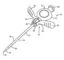
- FIG. 1illustrates a perspective view of a conventional introducer assembly 10 comprising a dilator 12 and an introducer sheath 30 .
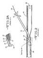
- FIG. 2illustrates a partial sectional view of the introducer assembly 10 shown in FIG. 1 being placed inside a blood vessel 46 along a guidewire 44 .
- FIG. 2Aillustrates an expanded partial sectional view of the indicated area in FIG. 2 .
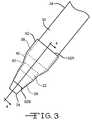
- FIG. 3illustrates a top view of the distal end of the introducer assembly 10 shown in FIG. 1 including a shroud 52 constructed in accordance with one embodiment of the current invention.
- FIG. 4is a partial cross-sectional view taken along line 4 - 4 of FIG. 3 .
- FIG. 5is a partial cross-sectional view of the introducer assembly 10 shown in FIG. 1 provided with another embodiment of a shroud 54 constructed in accordance with the present invention.
- FIG. 6illustrates a partial sectional view of the introducer assembly 10 provided with the shroud 52 shown in FIG. 3 after having been inserted into a blood vessel 46 .
- FIG. 7illustrates a partial sectional view of the introducer assembly 10 provided with the shroud 52 shown in FIG. 6 as the shroud is being degraded inside the blood vessel 46 .
- FIG. 1illustrates an introducer assembly 10 comprising a dilator 12 disposed inside an introducer 14 .
- the dilator 12has a dilator handle 16 supported at the proximal end of a dilator tube 18 ( FIGS. 4 to 7 ).
- the dilator tube 18comprises a dilator sidewall 20 surrounding a lumen extending along the entire length thereof including the handle 16 to a distal portion 22 having an open end 24 .
- the dilator tube 18has a uniform circular cross-section normal to the longitudinal axis of the sidewall 20 extending along the majority of its length from the handle 16 to the distal portion 22 .
- the dilator sidewall 20has a taper 26 that progressively narrows to the distal open end 24 of a reduced diameter.
- the lumen through the dilator 12 including the handle 16 and the tube 18is of a uniform diameter. This means that the thickness of the sidewall 20 becomes thinner at the distal portion 22 to provide the taper 26 to the distal open end 24 .
- the dilator 12is formed of, in an example, high density polyethylene, polypropylene, polyurethane, or fluorinated polymers such as, but not limited to, PTFE (polytetrafluoroethylene), FEP (fluorinated ethylene-propylene).
- the introducer 14comprises an introducer sheath 30 that is coupled with a handle 32 .
- the introducer sheath 30is comprised of a tubular sidewall 34 surrounding an open passage extending from a sheath proximal portion 36 supported by the handle 32 to a sheath distal portion 38 .
- the sheath distal portion 38has a taper 40 that progressively narrows from a larger outer diameter extending along a majority of the length of the sheath tubular sidewall 34 to an open sheath end 42 of the distal portion 38 .
- the diameter of the sheath lumendoes not reduce in diameter along its entire length. This means that the taper 40 is formed by a reduction in the thickness of the tubular sidewall 34 from one thickness along the majority of the length thereof to a reduced thickness at the open sheath end 42 .
- the taper 40( FIGS. 3 to 5 ) provides a slender profile from the introducer sheath 30 to the dilator 12 disposed through the sheath lumen.
- the dilator taper 26facilitates insertion of the introducer assembly 10 into a patient, for example, over a guidewire 44 .
- the dilator handle 16optionally includes features, such as a luer hub or threads 16 A, that allows for other devices to be coupled thereto.
- the introducer sheath 30is formed of, in an example, fluorinated polymers such as, but not limited to, PTFE (polytetrafluoroethylene) and FEP (fluorinated ethylene-propylene), and non-fluorinated polymers, such as, but not limited to, polyethylene, polypropylene, nylon or polyimide.
- the sheath materialsuch as PTFE, can be molecularly oriented for optionally splitting the introducer sheath 30 .
- Molecularly oriented sheathsdo not necessarily require an additional mechanical scoring operation to produce split lines, as in the case of a polyethylene sheath. Instead, the oriented molecules allow the introducer sheath 30 to naturally peel like a banana.
- the introducer handle 32is typically provided with diametrically opposed score lines or some similar form of linear weakening to facilitate its removal along with the introducer sheath 30 .
- FIGS. 2 and 2Adepict the introducer assembly 10 shown in FIG. 1 including the dilator 12 received inside the lumen of the introducer sheath 14 being inserted into a body over a guidewire 44 according to the prior art.
- the bodyis part of the venous system 46 .
- a hollow needle(not shown) is first inserted into the venous system 46 crossing the skin 48 and other tissue until its distal end is in a desired location.
- the guidewire 44is next inserted into the venous system 46 through the needle, and the needle is removed over the guidewire, leaving the guidewire in the vessel.
- the introducer assembly 10 including the dilator 12 partially housed inside the introducer 14is inserted over the guidewire 44 into the venous system 46 and advanced to a suitable position so that the distal portion 38 of the introducer sheath 30 is well within the vessel but both the dilator handle 16 and the introducer handle 32 are outside the patient. With the introducer assembly 10 in the vessel, the guidewire 44 and dilator 12 are removed sequentially, leaving only the introducer sheath 30 therein.
- the taper 40 at the distal portion 38 of the introducer sheath 30 narrowing down to the taper 26 at the distal portion 22 of the dilator 12normally facilitates relatively easy insertion of the introducer assembly 10 into the body.
- the distal portion 22 of the dilator 12 and the distal portion 38 of the introducer sheath 30normally bend upon entering the blood vessel 46 and as they follow the path of the guidewire 44 .
- FIG. 1shows that
- this distal bendingmay create a zone of increased “fish mouth” separation 50 between the dilator's distal portion 22 and the introducer sheath's distal portion 38 as the introducer assembly 10 encounters different tissue layers.
- This separation 50can occur if the bending force exerted by the tissue, or the blood vessel wall, on the distal open end 24 of the dilator 12 is higher than that on the distal open end 42 of the sheath 30 .
- the mechanical strengths of the respective distal ends of the dilator 12 and the introducer sheath 30are different. Different materials of construction for the dilator 12 and the introducer 14 can cause this, or there may be dimensional differences between their respective open ends.
- this separation 50can cause the distal open end 42 of the introducer sheath 30 to cut into tissue during advancement of the introducer assembly 10 along the insertion path of the guidewire 44 , resulting in internal bleeding. Tissue can also get caught in the distal open end 42 of the introducer sheath 30 and impede advancement of the introducer assembly 10 along the guidewire 44 . If the impeding force is high enough, the distal portion 38 of the introducer sheath 30 can be deformed or even damaged.
- the shroud 52continuously covers the distal portion 38 of the introducer sheath 30 and extends over at least some of the distal portion 22 of the dilator 12 .
- the shroud 52is preferably of a biodegradable material that is conformably deposited on the introducer assembly 10 to continuously cover the distal portion 38 of the introducer sheath 30 to a position proximate the open end 24 of the distal dilator portion 22 .
- the shroud 52tapers from a shroud proximal end 52 A to a shroud distal end 52 B. This not only helps minimize resistance of the dilator 12 and introducer sheath 30 to movement through the vasculature 46 , but also resistance attendant to the shroud 52 itself is minimized.
- degradable materialsinclude, but are not limited to, mannitol (hexan-1,2,3,4,5,6-hexol (C 6 H 8 (OH) 6 ) is a sugar alcohol or a polyol), gelatin, starch, cellulose, alginate, hyaluronic acid, polylactides (PLA), polyglycolides (PGA), polycaprolactone (PCL) and copolymers, non-cross linked water soluble salts of chitosan, or inorganic salt, such as sodium chloride mixtures, and combinations thereof.
- the term “degradable”refers to a partial or a complete degradation of the material integrity of the shroud 52 , which occurs through contact with blood or other body fluids. Such degradation can include dissolution, hydrolytic degradation, bioabsorption, and other degradation mechanisms well known to those skilled in the art.
- FIG. 6illustrates insertion of the introducer assembly 10 including the shroud 52 into a blood vessel 46 after crossing the skin 48 and other tissue layers.
- the thin shroud 52covers the distal portion 38 of the introducer sheath 30 including the open sheath end 42 and extends along a majority of the length of the distal portion 22 of the dilator 12 .
- the shroud 52prevents direct contact between the open sheath end 42 and the tissue.
- the shroud 52virtually eliminates any possibility that blood vessel tissue will be damages by the open sheath end 42 at the separation zone 50 .
- the shroud 52is made of a material having a thickness of from about 0.01 mm to about 1 mm and that degrades after contact with blood within a pre-determined period of time. Use of the shroud 52 is in direct contrast to the potentially damaging situation illustrated in FIGS. 2 and 2A .
- the shroud 52can be made by any one of a number of coating processes including, but are not limited to, dip coating, spray coating, and vapor deposition.
- the shroud 52can also be attached to the distal portions 22 and 38 of the introducer assembly 10 as a prefabricated thin film. Attaching methods includes, but are not limited to, gluing, heat reflow and mechanical interference fitting.
- the maximum pre-determined time for a partial or a complete degradation of the shroud 52should be less than 30 seconds.
- the preferred timeis about 15 seconds with the actual degradation period being controlled by the selection of the degradable material and the thickness of the shroud material, especially at the dilator/sheath transition.
- a shroud 52 comprising mannitolshould have a thickness of from about 0.03 mm to about 0.1 mm.
- FIG. 7illustrates the biodegradable shroud 52 in a partially degraded condition after being placed inside the blood vessel 46 .
- the shroud 52is weakened through contact with blood to enable relatively easy separation and removal of the dilator 12 from the introducer sheath 30 after introducer placement. This weakening is associated with one or more of a combination of the degradation mechanisms discussed above.
- FIG. 5illustrates a further embodiment of a shroud 54 according to the current invention.
- the shroud 54is composed of an outer layer 56 and an inner layer 58 .
- Multi-layer structurescan be used to fine tune the shroud's required mechanic strength during insertion, and the required speed of degradation after insertion.
- the distal portion 38 of the introducer sheath 30 housing the distal portion 22 of the dilator 12is dip coated in a 15 wt % mannitol aqueous solution to form the inner layer 58 having a thickness of about 0.05 mm.
- This sub-assemblyis then dip coated in a second mannitol aqueous solution containing 10 wt % of mannitol and 10 wt % of sodium chloride (NaCl).
- the second outer layerhas a thickness of about 0.1 mm.
- FIG. 5illustrates a shroud 54 comprising two layers 56 , 58 , that should not be viewed as limiting. Shrouds of three or more layers are contemplated by the scope of the present invention. However, in any such multi-layer construction, it's preferred that the outer layer 56 degrades faster than the inner layer 58 . Having a multi-layer shroud construction may be beneficial to tailor the slip resistance and structural integrity of the shroud. For example, it may be beneficial to provide the outer layer 56 with a high degree of lubricity, but that may detrimentally impact its structural integrity. A lack of structural integrity can be compensated for by having the inner layer 58 being somewhat more durable than the outer layer 56 .
- the dilator 12is removable from the introducer sheath 30 to allow other instruments to enter the blood vessel through the sheath inner lumen.
- the medical procedureis then performed in its normal manner, for example, placement of a cardiac lead, and the like.
- the physicianremoves the introducer 14 without disturbing the lead. This is done by holding the wings 60 , 62 of the introducer 14 shown in FIG. 1 between the thumb and fore finger and counter rotating them with respect to each other while slowly moving the wings further apart.
- the introducer valve housing 64 including a valve membrane (not shown) supported thereinis readily separated. This occurs at a score line 66 running along the valve housing 64 and the valve membrane supported therein.
- the tubular sidewall 34 of the introducer sheath 30does not require a score line. Instead, it is made of PTFE which has a unique molecular structure. Once a sufficient amount of force is exerted at opposed stress points (not shown) provided at the proximal end of the tubular sidewall 34 underneath the valve housing 64 , the PTFE molecules begin to sever. Further pulling force causes the resulting tear to propagate in a linear manner along the entire length of the sheath tubular sidewall 34 to its distal end 42 . The tear is extremely straight and parallel to the longitudinal axis of the sheath 14 .
- the tearis smooth and provides the physician with an even tactile feel that gives the physician a high degree of confidence that the lead, and the like, was not disturbed during removal of the introducer 14 from the venous system. 46 .
- U.S. Provisional Application Ser. No. 61/107,447filed Oct. 22, 2008. This application is assigned to the assignee of the present invention and incorporated herein by reference.
- Another technique for removing the introducer 14is to pull it out of the venous system against the cutting edge of the slitter (not shown) as the lead or like medical device remains positioned in the body. This technique is well known by those skilled in the art.
Landscapes
- Health & Medical Sciences (AREA)
- Life Sciences & Earth Sciences (AREA)
- Public Health (AREA)
- Animal Behavior & Ethology (AREA)
- General Health & Medical Sciences (AREA)
- Veterinary Medicine (AREA)
- Biomedical Technology (AREA)
- Heart & Thoracic Surgery (AREA)
- Hematology (AREA)
- Anesthesiology (AREA)
- Engineering & Computer Science (AREA)
- Biophysics (AREA)
- Pulmonology (AREA)
- Epidemiology (AREA)
- Media Introduction/Drainage Providing Device (AREA)
Abstract
Description
Claims (21)
Priority Applications (1)
| Application Number | Priority Date | Filing Date | Title |
|---|---|---|---|
| US12/357,732US8109908B1 (en) | 2008-01-22 | 2009-01-22 | Biodegradable shroud for a dilator/sheath assembly |
Applications Claiming Priority (2)
| Application Number | Priority Date | Filing Date | Title |
|---|---|---|---|
| US2265108P | 2008-01-22 | 2008-01-22 | |
| US12/357,732US8109908B1 (en) | 2008-01-22 | 2009-01-22 | Biodegradable shroud for a dilator/sheath assembly |
Publications (1)
| Publication Number | Publication Date |
|---|---|
| US8109908B1true US8109908B1 (en) | 2012-02-07 |
Family
ID=45532211
Family Applications (1)
| Application Number | Title | Priority Date | Filing Date |
|---|---|---|---|
| US12/357,732Expired - Fee RelatedUS8109908B1 (en) | 2008-01-22 | 2009-01-22 | Biodegradable shroud for a dilator/sheath assembly |
Country Status (1)
| Country | Link |
|---|---|
| US (1) | US8109908B1 (en) |
Cited By (11)
| Publication number | Priority date | Publication date | Assignee | Title |
|---|---|---|---|---|
| US20120095432A1 (en)* | 2010-10-15 | 2012-04-19 | Nath Iyunni Venkata Sesha Sayi | Catheter and method of insertion |
| US20140025003A1 (en)* | 2011-07-22 | 2014-01-23 | Greatbatch Ltd. | Introducer Handle Notch Design/Concept |
| US20140371676A1 (en)* | 2013-05-08 | 2014-12-18 | Clph, Llc | Catheters and dilators for trans-septal procedures and methods for making and using them |
| US9078991B2 (en) | 2013-03-04 | 2015-07-14 | Vascular Solutions, Inc. | Vascular dilator systems, kits, and methods |
| EP2929898A1 (en)* | 2014-04-10 | 2015-10-14 | Cook Medical Technologies LLC | Introducer assembly and protective sleeve therefor |
| WO2016122962A1 (en)* | 2015-01-27 | 2016-08-04 | Mayo Foundation For Medical Education And Research | Dissolvable dilator |
| CN105832424A (en)* | 2016-03-17 | 2016-08-10 | 中国人民解放军第三军医大学第二附属医院 | Medical expanding protective cover and using method thereof |
| WO2016126299A1 (en)* | 2015-02-04 | 2016-08-11 | Teleflex Medical Incorporated | Flexible tip dilator |
| WO2021113962A1 (en) | 2019-12-09 | 2021-06-17 | Mg Stroke Analytics Inc. | Systems and methods for accessing small arteries for conveying catheters to target vessels |
| EP3888732A1 (en)* | 2014-11-14 | 2021-10-06 | Access Closure, Inc. | Devices for flow occlusion during device exchanges |
| US11759259B2 (en)* | 2008-12-16 | 2023-09-19 | Nico Corporation | Tissue removal device with adjustable delivery sleeve for neurosurgical and spinal surgery applications |
Citations (15)
| Publication number | Priority date | Publication date | Assignee | Title |
|---|---|---|---|---|
| US4827940A (en)* | 1987-04-13 | 1989-05-09 | Cardiac Pacemakers, Inc. | Soluble covering for cardiac pacing electrode |
| US4876109A (en) | 1987-04-13 | 1989-10-24 | Cardiac Pacemakers, Inc. | Soluble covering for cardiac pacing electrode |
| US5531783A (en) | 1995-01-17 | 1996-07-02 | Vitatron Medical, B.V. | Pacing lead with x-ray visible soluble covering and method of inserting same into a patient's heart |
| US5994444A (en) | 1997-10-16 | 1999-11-30 | Medtronic, Inc. | Polymeric material that releases nitric oxide |
| US6304786B1 (en) | 1999-03-29 | 2001-10-16 | Cardiac Pacemakers, Inc. | Implantable lead with dissolvable coating for improved fixation and extraction |
| US20010049502A1 (en) | 1998-11-25 | 2001-12-06 | Light Sciences Corporation | Guide sheath for repeated placement of a device |
| US6409674B1 (en) | 1998-09-24 | 2002-06-25 | Data Sciences International, Inc. | Implantable sensor with wireless communication |
| US6522915B1 (en) | 2000-10-26 | 2003-02-18 | Medtronic, Inc. | Surround shroud connector and electrode housings for a subcutaneous electrode array and leadless ECGS |
| US6631290B1 (en) | 2000-10-25 | 2003-10-07 | Medtronic, Inc. | Multilayer ceramic electrodes for sensing cardiac depolarization signals |
| US20030233115A1 (en) | 2002-04-25 | 2003-12-18 | Eversull Christian Scott | Expandable guide sheath and apparatus and methods using such sheaths |
| US20050113900A1 (en) | 2003-10-24 | 2005-05-26 | Cardiac Pacemakers, Inc. | Myocardial lead with fixation mechanism |
| US6939328B2 (en)* | 2002-02-27 | 2005-09-06 | Medical Components, Inc. | Dissolvable subcutaneous catheter cover |
| US7089046B2 (en) | 1999-07-29 | 2006-08-08 | Cardiac Pacemakers, Inc. | Removable cap for tissue-insertable connections |
| US20070065481A1 (en) | 2005-09-21 | 2007-03-22 | Chudzik Stephen J | Coatings including natural biodegradable polysaccharides and uses thereof |
| US20070077271A1 (en) | 2005-07-21 | 2007-04-05 | Michael Dornish | Medical devices coated with a fast dissolving biocompatible coating |
- 2009
- 2009-01-22USUS12/357,732patent/US8109908B1/ennot_activeExpired - Fee Related
Patent Citations (16)
| Publication number | Priority date | Publication date | Assignee | Title |
|---|---|---|---|---|
| US4876109A (en) | 1987-04-13 | 1989-10-24 | Cardiac Pacemakers, Inc. | Soluble covering for cardiac pacing electrode |
| US4827940A (en)* | 1987-04-13 | 1989-05-09 | Cardiac Pacemakers, Inc. | Soluble covering for cardiac pacing electrode |
| US5531783A (en) | 1995-01-17 | 1996-07-02 | Vitatron Medical, B.V. | Pacing lead with x-ray visible soluble covering and method of inserting same into a patient's heart |
| US5994444A (en) | 1997-10-16 | 1999-11-30 | Medtronic, Inc. | Polymeric material that releases nitric oxide |
| US6409674B1 (en) | 1998-09-24 | 2002-06-25 | Data Sciences International, Inc. | Implantable sensor with wireless communication |
| US20010049502A1 (en) | 1998-11-25 | 2001-12-06 | Light Sciences Corporation | Guide sheath for repeated placement of a device |
| US6584363B2 (en) | 1999-03-29 | 2003-06-24 | Cardiac Pacemakers, Inc. | Implantable lead with dissolvable coating for improved fixation and extraction |
| US6304786B1 (en) | 1999-03-29 | 2001-10-16 | Cardiac Pacemakers, Inc. | Implantable lead with dissolvable coating for improved fixation and extraction |
| US7089046B2 (en) | 1999-07-29 | 2006-08-08 | Cardiac Pacemakers, Inc. | Removable cap for tissue-insertable connections |
| US6631290B1 (en) | 2000-10-25 | 2003-10-07 | Medtronic, Inc. | Multilayer ceramic electrodes for sensing cardiac depolarization signals |
| US6522915B1 (en) | 2000-10-26 | 2003-02-18 | Medtronic, Inc. | Surround shroud connector and electrode housings for a subcutaneous electrode array and leadless ECGS |
| US6939328B2 (en)* | 2002-02-27 | 2005-09-06 | Medical Components, Inc. | Dissolvable subcutaneous catheter cover |
| US20030233115A1 (en) | 2002-04-25 | 2003-12-18 | Eversull Christian Scott | Expandable guide sheath and apparatus and methods using such sheaths |
| US20050113900A1 (en) | 2003-10-24 | 2005-05-26 | Cardiac Pacemakers, Inc. | Myocardial lead with fixation mechanism |
| US20070077271A1 (en) | 2005-07-21 | 2007-04-05 | Michael Dornish | Medical devices coated with a fast dissolving biocompatible coating |
| US20070065481A1 (en) | 2005-09-21 | 2007-03-22 | Chudzik Stephen J | Coatings including natural biodegradable polysaccharides and uses thereof |
Cited By (18)
| Publication number | Priority date | Publication date | Assignee | Title |
|---|---|---|---|---|
| US11759259B2 (en)* | 2008-12-16 | 2023-09-19 | Nico Corporation | Tissue removal device with adjustable delivery sleeve for neurosurgical and spinal surgery applications |
| US20120095432A1 (en)* | 2010-10-15 | 2012-04-19 | Nath Iyunni Venkata Sesha Sayi | Catheter and method of insertion |
| US9517323B2 (en) | 2011-07-22 | 2016-12-13 | Greatbatch Ltd. | Introducer handle notch design/concept |
| US20140025003A1 (en)* | 2011-07-22 | 2014-01-23 | Greatbatch Ltd. | Introducer Handle Notch Design/Concept |
| US8753313B2 (en)* | 2011-07-22 | 2014-06-17 | Greatbatch Ltd. | Introducer handle notch design/concept |
| US9078991B2 (en) | 2013-03-04 | 2015-07-14 | Vascular Solutions, Inc. | Vascular dilator systems, kits, and methods |
| US20140371676A1 (en)* | 2013-05-08 | 2014-12-18 | Clph, Llc | Catheters and dilators for trans-septal procedures and methods for making and using them |
| US9775643B2 (en)* | 2013-05-08 | 2017-10-03 | Clph, Llc | Catheters and dilators for trans-septal procedures and methods for making and using them |
| US9895511B2 (en) | 2014-04-10 | 2018-02-20 | Cook Medical Technologies Llc | Introducer assembly and protective sleeve therefor |
| EP2929898A1 (en)* | 2014-04-10 | 2015-10-14 | Cook Medical Technologies LLC | Introducer assembly and protective sleeve therefor |
| EP3888732A1 (en)* | 2014-11-14 | 2021-10-06 | Access Closure, Inc. | Devices for flow occlusion during device exchanges |
| WO2016122962A1 (en)* | 2015-01-27 | 2016-08-04 | Mayo Foundation For Medical Education And Research | Dissolvable dilator |
| WO2016126299A1 (en)* | 2015-02-04 | 2016-08-11 | Teleflex Medical Incorporated | Flexible tip dilator |
| US9808598B2 (en) | 2015-02-04 | 2017-11-07 | Teleflex Medical Incorporated | Flexible tip dilator |
| CN105832424A (en)* | 2016-03-17 | 2016-08-10 | 中国人民解放军第三军医大学第二附属医院 | Medical expanding protective cover and using method thereof |
| CN105832424B (en)* | 2016-03-17 | 2018-11-20 | 中国人民解放军第三军医大学第二附属医院 | The medical expansion protective case of one kind and its application method |
| WO2021113962A1 (en) | 2019-12-09 | 2021-06-17 | Mg Stroke Analytics Inc. | Systems and methods for accessing small arteries for conveying catheters to target vessels |
| EP4072644A4 (en)* | 2019-12-09 | 2024-02-14 | MG Stroke Analytics Inc. | Systems and methods for accessing small arteries for conveying catheters to target vessels |
Similar Documents
| Publication | Publication Date | Title |
|---|---|---|
| US8109908B1 (en) | Biodegradable shroud for a dilator/sheath assembly | |
| US7837671B2 (en) | Slittable and peelable sheaths and methods for making and using them | |
| US20250018160A1 (en) | Hybrid transseptal dilator and methods of using the same | |
| JP6882275B2 (en) | Sheathless guide catheter assembly | |
| US8377084B1 (en) | Method of using a catheter for traversing total occlusions | |
| EP2956197B1 (en) | Steerable medical device having multiple curve profiles | |
| EP1196213B1 (en) | Catheter introducer system | |
| US7384422B2 (en) | Telescopic, separable introducer and method of using the same | |
| US6280433B1 (en) | Introducer system | |
| US6945956B2 (en) | Steerable catheter | |
| US8747428B2 (en) | Carotid sheath with entry and tracking rapid exchange dilators and method of use | |
| JP7155269B2 (en) | Guided extension catheter | |
| US20120157854A1 (en) | System and method for gaining percutaneous access to a body lumen | |
| AU766038B2 (en) | Finishing technique for a guiding catheter | |
| US11020224B2 (en) | Methods for exchanging devices | |
| EP0963179B1 (en) | Improved device for removing fibrin sheaths from catheters | |
| CN212997906U (en) | Vascular access sleeve and access system | |
| EP1259281A1 (en) | Medical introducer apparatus | |
| JP2008523910A (en) | Operable guide catheter and method of using the same | |
| AU2001247237A1 (en) | Medical introducer apparatus | |
| US20190015637A1 (en) | Methods for exchanging devices | |
| US20010051790A1 (en) | Finishing technique for a guiding catheter | |
| JP4586545B2 (en) | Balloon catheter | |
| Mao et al. | Conventional Endovascular Devices | |
| CA2603109C (en) | Finishing technique for a guiding catheter |
Legal Events
| Date | Code | Title | Description |
|---|---|---|---|
| AS | Assignment | Owner name:GREATBATCH LTD., NEW YORK Free format text:ASSIGNMENT OF ASSIGNORS INTEREST;ASSIGNORS:KRAUS, MARK C.;YE, QINGSHAN;SIGNING DATES FROM 20090204 TO 20090226;REEL/FRAME:022329/0458 | |
| ZAAA | Notice of allowance and fees due | Free format text:ORIGINAL CODE: NOA | |
| ZAAB | Notice of allowance mailed | Free format text:ORIGINAL CODE: MN/=. | |
| STCF | Information on status: patent grant | Free format text:PATENTED CASE | |
| AS | Assignment | Owner name:MANUFACTURERS AND TRADERS TRUST COMPANY (AS ADMINI Free format text:GRANT OF SECURITY INTEREST;ASSIGNORS:GREATBATCH LTD;ELECTROCHEM SOLUTIONS, INC.;NEURONEXUS TECHNOLOGIES, INC.;AND OTHERS;REEL/FRAME:031290/0278 Effective date:20130920 | |
| FPAY | Fee payment | Year of fee payment:4 | |
| AS | Assignment | Owner name:MANUFACTURERS AND TRADERS TRUST COMPANY, NEW YORK Free format text:SECURITY INTEREST;ASSIGNORS:GREATBATCH, INC.;GREATBATCH LTD.;ELECTROCHEM SOLUTIONS, INC.;AND OTHERS;REEL/FRAME:036980/0482 Effective date:20151027 | |
| MAFP | Maintenance fee payment | Free format text:PAYMENT OF MAINTENANCE FEE, 8TH YEAR, LARGE ENTITY (ORIGINAL EVENT CODE: M1552); ENTITY STATUS OF PATENT OWNER: LARGE ENTITY Year of fee payment:8 | |
| AS | Assignment | Owner name:WELLS FARGO BANK, NATIONAL ASSOCIATION, AS ADMINISTRATIVE AGENT, VIRGINIA Free format text:SECURITY INTEREST;ASSIGNORS:GREATBATCH LTD.;ELECTROCHEM SOLUTIONS, INC.;LAKE REGION MEDICAL, INC.;AND OTHERS;REEL/FRAME:057468/0056 Effective date:20210902 | |
| AS | Assignment | Owner name:MICRO POWER ELECTRONICS, INC., NEW YORK Free format text:RELEASE BY SECURED PARTY;ASSIGNOR:MANUFACTURERS AND TRADERS TRUST COMPANY (AS ADMINISTRATIVE AGENT);REEL/FRAME:060938/0069 Effective date:20210903 Owner name:PRECIMED INC., NEW YORK Free format text:RELEASE BY SECURED PARTY;ASSIGNOR:MANUFACTURERS AND TRADERS TRUST COMPANY (AS ADMINISTRATIVE AGENT);REEL/FRAME:060938/0069 Effective date:20210903 Owner name:GREATBATCH-GLOBE TOOL, INC., NEW YORK Free format text:RELEASE BY SECURED PARTY;ASSIGNOR:MANUFACTURERS AND TRADERS TRUST COMPANY (AS ADMINISTRATIVE AGENT);REEL/FRAME:060938/0069 Effective date:20210903 Owner name:NEURONEXUS TECHNOLOGIES, INC., NEW YORK Free format text:RELEASE BY SECURED PARTY;ASSIGNOR:MANUFACTURERS AND TRADERS TRUST COMPANY (AS ADMINISTRATIVE AGENT);REEL/FRAME:060938/0069 Effective date:20210903 Owner name:ELECTROCHEM SOLUTIONS, INC., NEW YORK Free format text:RELEASE BY SECURED PARTY;ASSIGNOR:MANUFACTURERS AND TRADERS TRUST COMPANY (AS ADMINISTRATIVE AGENT);REEL/FRAME:060938/0069 Effective date:20210903 Owner name:GREATBATCH LTD., NEW YORK Free format text:RELEASE BY SECURED PARTY;ASSIGNOR:MANUFACTURERS AND TRADERS TRUST COMPANY (AS ADMINISTRATIVE AGENT);REEL/FRAME:060938/0069 Effective date:20210903 Owner name:GREATBATCH, INC., NEW YORK Free format text:RELEASE BY SECURED PARTY;ASSIGNOR:MANUFACTURERS AND TRADERS TRUST COMPANY (AS ADMINISTRATIVE AGENT);REEL/FRAME:060938/0069 Effective date:20210903 Owner name:MICRO POWER ELECTRONICS, INC., NEW YORK Free format text:RELEASE BY SECURED PARTY;ASSIGNOR:MANUFACTURERS AND TRADERS TRUST COMPANY (AS ADMINISTRATIVE AGENT);REEL/FRAME:058649/0728 Effective date:20210903 Owner name:NEURONEXUS TECHNOLOGIES, INC., NEW YORK Free format text:RELEASE BY SECURED PARTY;ASSIGNOR:MANUFACTURERS AND TRADERS TRUST COMPANY (AS ADMINISTRATIVE AGENT);REEL/FRAME:058649/0728 Effective date:20210903 Owner name:ELECTROCHEM SOLUTIONS, INC., NEW YORK Free format text:RELEASE BY SECURED PARTY;ASSIGNOR:MANUFACTURERS AND TRADERS TRUST COMPANY (AS ADMINISTRATIVE AGENT);REEL/FRAME:058649/0728 Effective date:20210903 Owner name:GREATBATCH, LTD, NEW YORK Free format text:RELEASE BY SECURED PARTY;ASSIGNOR:MANUFACTURERS AND TRADERS TRUST COMPANY (AS ADMINISTRATIVE AGENT);REEL/FRAME:058649/0728 Effective date:20210903 | |
| AS | Assignment | Owner name:MICRO POWER ELECTRONICS, INC., NEW YORK Free format text:RELEASE BY SECURED PARTY;ASSIGNOR:MANUFACTURERS AND TRADERS TRUST COMPANY (AS ADMINISTRATIVE AGENT);REEL/FRAME:061659/0858 Effective date:20210903 Owner name:PRECIMED INC., NEW YORK Free format text:RELEASE BY SECURED PARTY;ASSIGNOR:MANUFACTURERS AND TRADERS TRUST COMPANY (AS ADMINISTRATIVE AGENT);REEL/FRAME:061659/0858 Effective date:20210903 Owner name:GREATBATCH-GLOBE TOOL, INC., NEW YORK Free format text:RELEASE BY SECURED PARTY;ASSIGNOR:MANUFACTURERS AND TRADERS TRUST COMPANY (AS ADMINISTRATIVE AGENT);REEL/FRAME:061659/0858 Effective date:20210903 Owner name:NEURONEXUS TECHNOLOGIES, INC., NEW YORK Free format text:RELEASE BY SECURED PARTY;ASSIGNOR:MANUFACTURERS AND TRADERS TRUST COMPANY (AS ADMINISTRATIVE AGENT);REEL/FRAME:061659/0858 Effective date:20210903 Owner name:ELECTROCHEM SOLUTIONS, INC., NEW YORK Free format text:RELEASE BY SECURED PARTY;ASSIGNOR:MANUFACTURERS AND TRADERS TRUST COMPANY (AS ADMINISTRATIVE AGENT);REEL/FRAME:061659/0858 Effective date:20210903 Owner name:GREATBATCH LTD., NEW YORK Free format text:RELEASE BY SECURED PARTY;ASSIGNOR:MANUFACTURERS AND TRADERS TRUST COMPANY (AS ADMINISTRATIVE AGENT);REEL/FRAME:061659/0858 Effective date:20210903 Owner name:GREATBATCH, INC., NEW YORK Free format text:RELEASE BY SECURED PARTY;ASSIGNOR:MANUFACTURERS AND TRADERS TRUST COMPANY (AS ADMINISTRATIVE AGENT);REEL/FRAME:061659/0858 Effective date:20210903 | |
| FEPP | Fee payment procedure | Free format text:MAINTENANCE FEE REMINDER MAILED (ORIGINAL EVENT CODE: REM.); ENTITY STATUS OF PATENT OWNER: LARGE ENTITY | |
| LAPS | Lapse for failure to pay maintenance fees | Free format text:PATENT EXPIRED FOR FAILURE TO PAY MAINTENANCE FEES (ORIGINAL EVENT CODE: EXP.); ENTITY STATUS OF PATENT OWNER: LARGE ENTITY | |
| STCH | Information on status: patent discontinuation | Free format text:PATENT EXPIRED DUE TO NONPAYMENT OF MAINTENANCE FEES UNDER 37 CFR 1.362 | |
| FP | Lapsed due to failure to pay maintenance fee | Effective date:20240207 |