US8109274B2 - Methods and electrode apparatus to achieve a closure of a layered tissue defect - Google Patents
Methods and electrode apparatus to achieve a closure of a layered tissue defectDownload PDFInfo
- Publication number
- US8109274B2 US8109274B2US11/403,052US40305206AUS8109274B2US 8109274 B2US8109274 B2US 8109274B2US 40305206 AUS40305206 AUS 40305206AUS 8109274 B2US8109274 B2US 8109274B2
- Authority
- US
- United States
- Prior art keywords
- tissue
- housing
- defect
- power
- catheter
- Prior art date
- Legal status (The legal status is an assumption and is not a legal conclusion. Google has not performed a legal analysis and makes no representation as to the accuracy of the status listed.)
- Active, expires
Links
- PNFSOXOJRQDAEU-UHFFFAOYSA-NCCC[O]1CC(C)=CC1Chemical compoundCCC[O]1CC(C)=CC1PNFSOXOJRQDAEU-UHFFFAOYSA-N0.000description1
Images


Classifications
- A—HUMAN NECESSITIES
- A61—MEDICAL OR VETERINARY SCIENCE; HYGIENE
- A61B—DIAGNOSIS; SURGERY; IDENTIFICATION
- A61B17/00—Surgical instruments, devices or methods
- A61B17/0057—Implements for plugging an opening in the wall of a hollow or tubular organ, e.g. for sealing a vessel puncture or closing a cardiac septal defect
- A—HUMAN NECESSITIES
- A61—MEDICAL OR VETERINARY SCIENCE; HYGIENE
- A61B—DIAGNOSIS; SURGERY; IDENTIFICATION
- A61B18/00—Surgical instruments, devices or methods for transferring non-mechanical forms of energy to or from the body
- A61B18/04—Surgical instruments, devices or methods for transferring non-mechanical forms of energy to or from the body by heating
- A61B18/12—Surgical instruments, devices or methods for transferring non-mechanical forms of energy to or from the body by heating by passing a current through the tissue to be heated, e.g. high-frequency current
- A61B18/14—Probes or electrodes therefor
- A61B18/1492—Probes or electrodes therefor having a flexible, catheter-like structure, e.g. for heart ablation
- A—HUMAN NECESSITIES
- A61—MEDICAL OR VETERINARY SCIENCE; HYGIENE
- A61M—DEVICES FOR INTRODUCING MEDIA INTO, OR ONTO, THE BODY; DEVICES FOR TRANSDUCING BODY MEDIA OR FOR TAKING MEDIA FROM THE BODY; DEVICES FOR PRODUCING OR ENDING SLEEP OR STUPOR
- A61M25/00—Catheters; Hollow probes
- A61M25/0067—Catheters; Hollow probes characterised by the distal end, e.g. tips
- A61M25/0068—Static characteristics of the catheter tip, e.g. shape, atraumatic tip, curved tip or tip structure
- A61M25/0069—Tip not integral with tube
- A—HUMAN NECESSITIES
- A61—MEDICAL OR VETERINARY SCIENCE; HYGIENE
- A61M—DEVICES FOR INTRODUCING MEDIA INTO, OR ONTO, THE BODY; DEVICES FOR TRANSDUCING BODY MEDIA OR FOR TAKING MEDIA FROM THE BODY; DEVICES FOR PRODUCING OR ENDING SLEEP OR STUPOR
- A61M25/00—Catheters; Hollow probes
- A61M25/10—Balloon catheters
- A—HUMAN NECESSITIES
- A61—MEDICAL OR VETERINARY SCIENCE; HYGIENE
- A61B—DIAGNOSIS; SURGERY; IDENTIFICATION
- A61B17/00—Surgical instruments, devices or methods
- A61B17/00491—Surgical glue applicators
- A61B2017/00504—Tissue welding
- A—HUMAN NECESSITIES
- A61—MEDICAL OR VETERINARY SCIENCE; HYGIENE
- A61B—DIAGNOSIS; SURGERY; IDENTIFICATION
- A61B17/00—Surgical instruments, devices or methods
- A61B2017/00535—Surgical instruments, devices or methods pneumatically or hydraulically operated
- A61B2017/00557—Surgical instruments, devices or methods pneumatically or hydraulically operated inflatable
- A—HUMAN NECESSITIES
- A61—MEDICAL OR VETERINARY SCIENCE; HYGIENE
- A61B—DIAGNOSIS; SURGERY; IDENTIFICATION
- A61B17/00—Surgical instruments, devices or methods
- A61B2017/00535—Surgical instruments, devices or methods pneumatically or hydraulically operated
- A61B2017/00561—Surgical instruments, devices or methods pneumatically or hydraulically operated creating a vacuum
- A—HUMAN NECESSITIES
- A61—MEDICAL OR VETERINARY SCIENCE; HYGIENE
- A61B—DIAGNOSIS; SURGERY; IDENTIFICATION
- A61B17/00—Surgical instruments, devices or methods
- A61B17/0057—Implements for plugging an opening in the wall of a hollow or tubular organ, e.g. for sealing a vessel puncture or closing a cardiac septal defect
- A61B2017/00575—Implements for plugging an opening in the wall of a hollow or tubular organ, e.g. for sealing a vessel puncture or closing a cardiac septal defect for closure at remote site, e.g. closing atrial septum defects
- A—HUMAN NECESSITIES
- A61—MEDICAL OR VETERINARY SCIENCE; HYGIENE
- A61B—DIAGNOSIS; SURGERY; IDENTIFICATION
- A61B17/00—Surgical instruments, devices or methods
- A61B17/22—Implements for squeezing-off ulcers or the like on inner organs of the body; Implements for scraping-out cavities of body organs, e.g. bones; for invasive removal or destruction of calculus using mechanical vibrations; for removing obstructions in blood vessels, not otherwise provided for
- A61B2017/22051—Implements for squeezing-off ulcers or the like on inner organs of the body; Implements for scraping-out cavities of body organs, e.g. bones; for invasive removal or destruction of calculus using mechanical vibrations; for removing obstructions in blood vessels, not otherwise provided for with an inflatable part, e.g. balloon, for positioning, blocking, or immobilisation
- A61B2017/22065—Functions of balloons
- A61B2017/22069—Immobilising; Stabilising
- A—HUMAN NECESSITIES
- A61—MEDICAL OR VETERINARY SCIENCE; HYGIENE
- A61B—DIAGNOSIS; SURGERY; IDENTIFICATION
- A61B18/00—Surgical instruments, devices or methods for transferring non-mechanical forms of energy to or from the body
- A61B2018/00315—Surgical instruments, devices or methods for transferring non-mechanical forms of energy to or from the body for treatment of particular body parts
- A61B2018/00345—Vascular system
- A61B2018/00351—Heart
- A—HUMAN NECESSITIES
- A61—MEDICAL OR VETERINARY SCIENCE; HYGIENE
- A61B—DIAGNOSIS; SURGERY; IDENTIFICATION
- A61B18/00—Surgical instruments, devices or methods for transferring non-mechanical forms of energy to or from the body
- A61B2018/00571—Surgical instruments, devices or methods for transferring non-mechanical forms of energy to or from the body for achieving a particular surgical effect
- A61B2018/0063—Sealing
- A—HUMAN NECESSITIES
- A61—MEDICAL OR VETERINARY SCIENCE; HYGIENE
- A61B—DIAGNOSIS; SURGERY; IDENTIFICATION
- A61B18/00—Surgical instruments, devices or methods for transferring non-mechanical forms of energy to or from the body
- A61B18/04—Surgical instruments, devices or methods for transferring non-mechanical forms of energy to or from the body by heating
- A61B18/12—Surgical instruments, devices or methods for transferring non-mechanical forms of energy to or from the body by heating by passing a current through the tissue to be heated, e.g. high-frequency current
- A61B18/14—Probes or electrodes therefor
- A61B2018/1405—Electrodes having a specific shape
- A61B2018/1407—Loop
- A—HUMAN NECESSITIES
- A61—MEDICAL OR VETERINARY SCIENCE; HYGIENE
- A61B—DIAGNOSIS; SURGERY; IDENTIFICATION
- A61B90/00—Instruments, implements or accessories specially adapted for surgery or diagnosis and not covered by any of the groups A61B1/00 - A61B50/00, e.g. for luxation treatment or for protecting wound edges
- A61B90/06—Measuring instruments not otherwise provided for
- A61B2090/061—Measuring instruments not otherwise provided for for measuring dimensions, e.g. length
- A—HUMAN NECESSITIES
- A61—MEDICAL OR VETERINARY SCIENCE; HYGIENE
- A61M—DEVICES FOR INTRODUCING MEDIA INTO, OR ONTO, THE BODY; DEVICES FOR TRANSDUCING BODY MEDIA OR FOR TAKING MEDIA FROM THE BODY; DEVICES FOR PRODUCING OR ENDING SLEEP OR STUPOR
- A61M25/00—Catheters; Hollow probes
- A61M25/10—Balloon catheters
- A61M2025/1043—Balloon catheters with special features or adapted for special applications
- A61M2025/105—Balloon catheters with special features or adapted for special applications having a balloon suitable for drug delivery, e.g. by using holes for delivery, drug coating or membranes
- A—HUMAN NECESSITIES
- A61—MEDICAL OR VETERINARY SCIENCE; HYGIENE
- A61M—DEVICES FOR INTRODUCING MEDIA INTO, OR ONTO, THE BODY; DEVICES FOR TRANSDUCING BODY MEDIA OR FOR TAKING MEDIA FROM THE BODY; DEVICES FOR PRODUCING OR ENDING SLEEP OR STUPOR
- A61M25/00—Catheters; Hollow probes
- A61M25/10—Balloon catheters
- A61M2025/1043—Balloon catheters with special features or adapted for special applications
- A61M2025/1052—Balloon catheters with special features or adapted for special applications for temporarily occluding a vessel for isolating a sector
- A—HUMAN NECESSITIES
- A61—MEDICAL OR VETERINARY SCIENCE; HYGIENE
- A61M—DEVICES FOR INTRODUCING MEDIA INTO, OR ONTO, THE BODY; DEVICES FOR TRANSDUCING BODY MEDIA OR FOR TAKING MEDIA FROM THE BODY; DEVICES FOR PRODUCING OR ENDING SLEEP OR STUPOR
- A61M25/00—Catheters; Hollow probes
- A61M25/10—Balloon catheters
- A61M2025/1043—Balloon catheters with special features or adapted for special applications
- A61M2025/1054—Balloon catheters with special features or adapted for special applications having detachable or disposable balloons
Definitions
- the inventiongenerally relates to medical devices and methods. More specifically, the invention relates to positioning closure devices, including energy based devices and methods for treatment of anatomic defects in human tissue, such as a patent foramen ovale (PFO), atrial septal defect (ASD), ventricular septal defect (VSD), patent ductus arteriosis (PDA), left atrial appendages (LAA), blood vessel wall defects and other defects having layered and apposed tissue structures.
- PFOpatent foramen ovale
- ASDatrial septal defect
- VSDventricular septal defect
- PDApatent ductus arteriosis
- LAAleft atrial appendages
- blood vessel wall defectsand other defects having layered and apposed tissue structures.
- Fetal blood circulationis very different from adult circulation. Because fetal blood is oxygenated by the placenta, rather than the fetal lungs, blood is generally shunted past the lungs to the peripheral tissues through a number of vessels and foramens that remain patent (i.e., open) during fetal life and typically close shortly after birth. For example, fetal blood passes directly from the right atrium through the foramen ovale into the left atrium, and a portion of blood circulating through the pulmonary artery trunk passes through the ductus arteriosus to the aorta. This fetal circulation is shown in FIG. 1 .
- Patent foramen ovalehas long been considered a relatively benign condition, since it typically has little effect on the body's circulation. More recently, however, it has been found that a significant number of strokes may be caused at least in part by PFOs. In some cases, a stroke may occur because a PFO allows blood containing small thrombi to flow directly from the venous circulation to the arterial circulation and into the brain, rather than flowing to the lungs where the thrombi can become trapped and gradually dissolved. In other cases, a thrombus might form in the patent channel of the PFO itself and become dislodged when the pressures cause blood to flow from the right atrium to the left atrium. It has been estimated that patients with PFOs who have already had cryptogenic strokes may have a risk of having another stroke.
- a number of interventional devices for closing defects percutaneouslyhave also been proposed and developed. Most of these devices are the same as or similar to ASD closure devices. They are typically “clamshell” or “double umbrella” shaped devices which deploy an area of biocompatible metal mesh or fabric (ePTFE or Dacron, for example) on each side of the atrial septum, held together with a central axial element, to cover the defect. This umbrella then heals into the atrial septum, with the healing response forming a uniform layer of tissue or “pannus” over the device.
- Such deviceshave been developed, for example, by companies such as Nitinol Medical Technologies, Inc. (Boston, Mass.) and AGA Medical, Inc. (White Bear Lake, Minn.).
- U.S. Pat. No. 6,401,720describes a method and apparatus for thoracoscopic intracardiac procedures which may be used for treatment of PFO.
- such methods and apparatuscould also be used in a minimally invasive manner, with low profile for ease of introduction into the body, while effectively closing the PFO quickly, effectively and without causing damage to other portions of the body.
- success of the closure procedurecan be well predicted, physicians are more likely to recommend such a procedure prophylacticly. At least some of these objectives will be met by the present invention.
- the present inventionprovides apparatus, systems and methods for treating anatomic defects in human tissues, particularly defects involving tissue layers where it is desired to weld or fuse the layers together, such as a patent foramen ovale (PFO).
- PFOpatent foramen ovale
- the methodswill also find use with closing a variety of other defects which may or may not display layered tissue structures, such as atrial septal defects, ventricular septal defects, patent ductus arteriosis, left atrial appendages, blood vessel wall defects, and the like.
- the apparatuswill usually comprise endovascular/intravascular catheters having an elongate catheter body with a proximal end and a distal end.
- a housingmay be positioned at or near a distal end of the catheter body, where the housing has an opening for engaging a tissue surface where the tissue defect may be present.
- the housingwill be connectable to a vacuum source to enhance engagement of the housing against the tissue, and an energy transmission member, such as an electrode, may be positioned at or near the opening in the housing to apply energy to the tissue to effect welding and closure.
- an energy transmission membersuch as an electrode
- sealing, closing, welding, fusingare used interchangeably to describe bringing tissues of a defect together so as to result in a substantial seal e.g. no physiologic leak of biological fluid or operator infused fluid across the sealed area.
- the sealing or closing of the defectcan occur via the presence or absence of a variety of biologic processes, some of which may be fusion or lamination of the tissue cells, layers or collagen, expression/combination of factors from the tissue that are expressed upon application of energy, denaturation and re-naturation of tissue elements, crosslinking, necrosis or partial necrosis or other cellular phenomena present at the treatment site upon application of the energies described herein, or combinations thereof.
- biologic processessome of which may be fusion or lamination of the tissue cells, layers or collagen, expression/combination of factors from the tissue that are expressed upon application of energy, denaturation and re-naturation of tissue elements, crosslinking, necrosis or partial necrosis or other cellular phenomena present at the treatment site upon application of the energies described herein, or combinations thereof.
- the suction housingmay be adapted for passage of a closure device such as a clip or fixation element that may be placed through the tissue of the defect while it is stabilized by the suction housing.
- a closure devicesuch as a clip or fixation element that may be placed through the tissue of the defect while it is stabilized by the suction housing.
- an apparatus for fusing a layered tissue structurecomprises a catheter body with proximal and distal ends, a housing on a distal portion of the catheter body and an energy transmission member associated with the housing.
- the energy transmission memberis configured to distribute energy over a predetermined pattern.
- an apparatus for fusing a layered tissue structurecomprises a catheter body having both proximal and distal ends, a vacuum housing on a distal portion of the catheter body and an energy transmission member disposed on or within the vacuum housing.
- the energy transmission memberalso has at least one opening which is adapted to receive tissue when a vacuum is applied to the housing.
- a method for fusing apposed layered tissue structurescomprises advancing a closure device at a first treatment site having apposed layers of tissue, applying energy from the closure device to the layers of tissue and controlling the applied energy to minimize creation of aberrant conductive paths and to enhance fusing at of the layers.
- the methodmay further include cooling down the closure device and the apposed layers to tissue and releasing the closure device away from the tissue structure.
- the methodincludes a closure device comprising a catheter body having a proximal end and a distal end, a housing on the distal portion of the catheter body and an energy transmission member associated with the housing is configured to deliver energy over a predetermined pattern.
- a methodgenerally takes the same form as the method previously described, except here, the method comprises a catheter body having a proximal and distal end, a vacuum housing on a distal portion of the catheter body and an energy transmission member disposed on or within the vacuum housing and having an opening adapted to receive tissue when a vacuum is applied to the housing.
- the energy transmission membermay be disposed over an opening in the housing and is adapted to allow the housing to appose the layered tissue structure.
- the energy transmission memberis collapsible and typically has an active surface.
- the energy transmission memberalso has an inactive surface.
- a non-conductive maskmay be used to define the active surface which may be variable. The non-conductive mask can be connected with the active region and forms an insulated region between the housing and the energy transmission member.
- the energy transmission memberis an electrode, and the geometry of the energy transmission member substantially approximates the layered tissue structure to be treated.
- the layered tissue structureis a patent foramen ovale (PFO) and the energy transmission member can treat PFOs ranging in size from about 1 mm to about 30 mm.
- the electrodemay be adapted to penetrate tissue.
- the energy transmission membercomprises a band which can be shaped in a number of ways, including elliptical, circular, rectangular, triangular and combinations thereof.
- Other patterns for the bandinclude an undulating wave-like pattern and the energy transmission member can also comprise a mesh, lobes or a bar.
- the barsIn the case of a bar, the bars have a length and a width and the bar length is often greater than the bar width.
- the barsmay have first and second regions which are hingedly connected or oppositely charged and adapted to deliver bipolar energy. The oppositely charged regions may alternatate.
- the barsmay interdigitate with one another or they may be substantially parallel to each other.
- the barsmay comprise an opening which can be a slit and the slit width is usually less than the bar width.
- Some embodimentsinclude a guidewire lumen disposed in the catheter body, passing through the housing and the lumen has an exit port between the bars.
- a rampmay be employed near the distal exit port.
- a vacuummay be applied through the bars which have been adapted so that tissue adherence is minimized and also allows a smooth interface with the layered tissue structure.
- the barscan also be adapted to form an edge from which energy is delivered.
- the energy transmission memberis usually biased toward a proximal portion of the housing in order to maximize the physical distance between the AV node of the human heart and an active portion of the energy transmission member when it is positioned over the layered tissue structure for treatment.
- General featuresmay include coating or plating the energy transmission member for either enhanced electrical or radiopaque characteristics.
- a guidewire portmay be disposed adjacent to the energy transmission member and a vacuum can be applied through the transmission member.
- struts in the energy transmission memberconnect it with the housing, or elastic elements flexibly connect the two together.
- a thermocouplemay be disposed near the energy transmission member in some embodiments and the housing can be adapted to allow fluid delivery to the layered tissue structure when the housing is apposed with the tissue.
- an apparatus for fusing a layered tissue structurecomprises an elongated catheter body with a proximal and distal end, and an energy transmission member connected with the elongated body.
- the energy transmission memberis adapted to appose the layered tissue structure and also adapted to deliver bipolar energy sufficient to fuse the structure.
- the energy transmission memberis a collapsible electrode which may be adapted to penetrate tissue.
- the energy transmission memberhas a geometry which substantially approximates the layered tissue structure to be treated and can treat a PFO with a size ranging from about 1 mm to about 30 mm.
- the closure devicecomprises an elongated catheter body with a proximal and distal end as well as an energy transmission member.
- the energy transmission memberis connected with the catheter and adapted to appose the layered tissue structure and fuse the structure upon.
- the energy transmission membermay comprise a ring, a mesh or bars.
- the apparatuscomprises a guidewire lumen axially disposed in the catheter body with a distal exit port adjacent to the energy transmission member.
- a rampmay be located near the distal exit port and a vacuum may be applied through the energy transmission member.
- the energy transmission memberis also adapted to minimize adherence with tissue. It also may be biased toward a proximal portion of the catheter body in order to maximize the physical distance between the AV node of the heart and the energy transmission member when it is positioned adjacent to the layered tissue structure to be treated.
- the energy transmission membermay be coated or plated for enhanced electrical characteristics or radiopacity.
- a vacuumis applied through the energy transmission member and a thermocouple may be adjacent to the energy transmission member.
- a system for fusing layered tissue structurecomprises a treatment catheter having an energy transmission member adapted to deliver energy deliver energy to the layered tissue structures and a controller connected to the treatment catheter.
- the controlleris programmed to vary an energy delivery parameter from the energy transmission member to the layered tissue structure to minimize creation of aberrant conductive paths and enhance fusing of adjacent tissue layers in the layered tissue structure.
- the controllercan be programmed to vary at least one parameter such as power, pulse rate, frequency and duration.
- the energy delivery parameteris typically varied in response to an algorithm which may depend upon a tissue response parameter.
- the systemoften includes one or more sensors for measuring a tissue response parameter while the size of the energy transmission member and/or the amount of energy delivered by the controller are selected to create a weld lesion having an effective size in the range from about 5 mm 2 to 90 mm 2 . In the case of a patent foramen ovale, the size of the energy transmission member and/or the amount of energy delivered by the controller are selected to create a weld lesion adequate to treat a PFO ranging in size from about 1 mm to about 30 mm.
- a method for fusing apposed layered tissue structurescomprises applying energy to the layered tissue structure and controlling the applied energy to minimize creation of aberrant conductive paths and enhance fusing of adjacent tissue layers in the tissue structure.
- Controlling the energytypically involves varying over time at least one parameter such as power, pulse rate, frequency, rate of increase, rate of decrease or duration.
- the power parameteris varied at least partially in response to an algorithm which may be dependent upon a tissue response parameter.
- the energyis also controlled to create a weld lesion having a predetermined size, typically in the range of 2 mm 2 to 400 mm 2 , and often in the range of 5 mm 2 to 90 mm 2 . Power is usually increased or decreased during a portion of the treatment cycle. If a tissue response parameter is used to control the power parameter, common tissue responses include tissue temperature, impedance and moisture.
- the methodalso comprises controlling power by applying power at an initial level of P 0 , increasing power to a higher level of P 1 over a time period of t 1 and then terminating power after a time period t 2 if no impedance spike occurs.
- the methodmay further comprise reducing or terminating power if an impedance spike occurs, reapplying power at a lower level P 2 over a time period t 3 and terminating the reapplied power if an impedance spike occurs.
- the methodalso can comprise controlling power by applying power at an initial level of P 0 and decreasing power if an impedance spike occurs. Power may be decreased if the impedance spike is observed within a predetermined time period, and power is terminated after a predetermined cumulative treatment time has passed.
- Other treatment parameters which may be used to control the procedureare selected based on patient characteristics and may include tissue characteristics and the nature of the defect being treated, which can be a patent foramen ovale.
- a method for fusing apposed layered tissue structurescomprises applying power to the apposed layered tissue structure an initial level P 0 , measuring tissue impedance including initial impedance Z 0 and increasing power by an amount k to a higher level after a given duration of time t 1 until a maximum power level P max is obtained. Power application is terminated if an impedance spike occurs and power has been applied for a given duration of time t 2 or longer.
- Additional stepscomprise temporarily stopping application of power if an impedance spike occurs and power has been applied for less than a given duration of time t 2 and re-applying power to the tissue structure at a power level P 1 lower than P 0 , if total power delivery time is less than t 3 , where t 3 is less than t 2 .
- Powermay be increased by an amount 2k if impedance has not exceeded its minimum value Z 0 by a given amount r after a time t 4 , where t 4 is greater than t 1 .
- the methodmay comprise increasing power by another amount 2k if impedance has not exceeded its minimum value Z 0 by a given amount r after a time t 4 .
- Power applicationis terminated when an impedance spike occurs and power has been applied for a given duration of time t 2 or longer.
- Poweris also stopped, temporarily if an impedance spike occurs and power has been applied for less than a given duration of time t 2 .
- Poweris then reapplied to the tissue structure at a power level P 1 , and lower than P 0 , if total power delivery time is less than t 3 , where t 3 is less than t 2 .
- the methodfurther comprises applying power at a level equal to P 1 +2k when total power application time prior to decreasing power to P 1 exceeds time t 3 .
- Poweris increased if impedance has not exceeded its minimum value after power was decreased to P 1 by r after a time t 4 , and power is terminated if an impedance spike occurs and power has been applied for a given duration of time t 2 or longer. Again, power may be temporarily stopped if an impedance spike occurs and power has been applied for less than a given duration of time t 2 .
- Poweris then re-applied to the tissue at a power level selected from the group consisting of P 1 , P 1 +2k and P 1 +4k. Again, if an impedance spike occurs, power application is terminated. In all cases, power application is terminated after application of power for a maximum time t max .
- FIG. 1illustrates the anatomy of fetal circulation, including a PFO and PDA.
- FIGS. 2A-2Ishow various anatomies of a PFO.
- FIGS. 3A-3Dshow various orientations of PFOs.
- FIGS. 4A-4Dshow how a treated PFO may not be fully sealed.
- FIGS. 5A-5Fshow various treated regions that successfully seal the PFO.
- FIG. 6shows a balloon properly positioning a closure device with respect to a layered tissue defect such as a PFO.
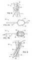
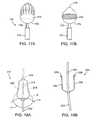
- FIGS. 7A and 7Bshow tapered elongated members or a tapered balloon on the distal end of a catheter used to position the catheter.
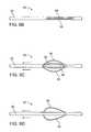
- FIG. 8shows a dual layer balloon in a layered tissue defect.
- FIGS. 9-9Aillustrate how expandable mechanical elements may be used to properly position a closure device at a layered tissue defect.
- FIGS. 9B-9Dshow expandable mechanical elements on a catheter shaft.
- FIGS. 10A-10Bshow an alternative embodiment of expandable mechanical positioning elements.
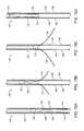
- FIG. 11shows how radiopaque markers on a flexible wire may be used to position a catheter and estimate tissue defect size.
- FIG. 12shows an alternative embodiment of a treatment device with flexible wires used for positioning and radiopaque markers for sizing and indicating treatment region.
- FIG. 12Ashows a crossing catheter with a guidewire lumen.
- FIG. 13is a cross-sectional view of a positioning device in the tunnel of a layered tissue defect.
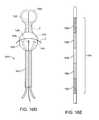
- FIG. 14illustrates how whiskers on a catheter position the device and indicate the width of the tunnel entrance.
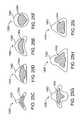
- FIGS. 15A-15Dshows a positioning device with retractable whiskers.
- FIGS. 16A-16Eillustrates a positioning device utilizing a looped wire design.
- FIGS. 17A-17Bshow other features on the closure device housing that facilitate with positioning.
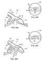
- FIGS. 18A-18Billustrate a compound bend in the closure device that assists with device positioning.
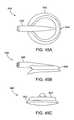
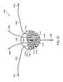
- FIGS. 19A-19Bshow various embodiments of a bipolar positioning and sizing closure device.
- FIG. 20illustrates a closure treatment system
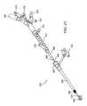
- FIG. 21shows a closure treatment apparatus
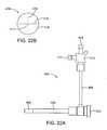
- FIGS. 22A-22Billustrates an introducer sheath and hemostasis valve used with a closure treatment apparatus.
- FIG. 23illustrates a collapsing introducer
- FIGS. 24A-24Eshow how the collapsing introducer of FIG. 23 is used.
- FIGS. 25A-25Bshow various aspects of the treatment catheter housing.
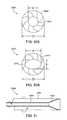
- FIGS. 25C-25Ishow a bottom view of several housing and electrode configurations.
- FIGS. 26-36show various ways a therapeutic element of a treatment device can appose defect tissue.
- FIG. 37shows one embodiment of an apposition device.
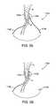
- FIGS. 38A-38Dshow an apposition device and how it apposes tissue.
- FIGS. 39A-39Fshow how an apposition device and a closure treatment device work together to close a layered tissue defect such as a PFO.
- FIGS. 39G-39Ishow another apposition device and closure treatment device working together to close a layered tissue defect such as a PFO.
- FIG. 40shows an apposition device comprising magnets.
- FIG. 41illustrates how magnets on either side of a PFO are used to bring the tissue layers together.
- FIG. 42shows magnets permanently implanted in order to close a PFO.
- FIG. 43shows additional features on the housing to help with tissue apposition.
- FIGS. 44A and 44Bshow other features on the housing that help with tissue apposition.
- FIGS. 45A-45Cshow a preferred embodiment of the closure device housing.
- FIGS. 45D-45Fshow another embodiment of the closure device housing.
- FIGS. 46-49Ashow various embodiments of electrode configurations.
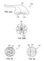
- FIGS. 50A-50Bshow a variable masking means.
- FIG. 51shows a means for actuating the variable masking of FIGS. 50A-50B .
- FIG. 51Ashows a mesh electrode embodiment
- FIG. 52A-52Bshow a looped or petal electrode configuration.
- FIGS. 53-54illustrate various electrode embodiments.
- FIG. 55shows a bipolar configuration
- FIG. 56shows a monopolar configuration
- FIG. 57shows a preferred embodiment of the electrode.
- FIG. 57Aillustrates a hinged electrode with flexible connections to the housing.
- FIG. 58A-58Cshow the electrode disposed in a housing and a portion of the guidewire lumen exit aperture.
- FIGS. 58D-58Fillustrate various aspects of an electrophysiological mapping system combined with the closure treatment device.
- FIG. 59is a schematic representation of a closure treatment system.
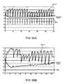
- FIGS. 60-67are graphs illustrating energy algorithms.
- Devices, systems, and methods of the present inventiongenerally provide for treatment of anatomic defects in human tissue, such as a patent foramen ovale (PFO), atrial septal defect (ASD), ventricular septal defect (VSD), left atrial appendage (LAA), patent ductus arteriosis (PDA), vessel wall defects and/or the like through application of energy.
- PFOpatent foramen ovale
- ASDatrial septal defect
- VSDventricular septal defect
- LAAleft atrial appendage
- PDApatent ductus arteriosis
- vessel wall defects and/or the likethrough application of energy.
- the present inventionis particularly useful for treating and fusing layered tissue structures where one layer of tissue at least partly overlaps a second layer of tissue as found in a PFO. Therefore, although the following descriptions and the referenced drawing figures focus primarily on treatment of PFO, any other suitable tissue defects, such as but not limited to those just listed, may be treated in various embodiments.
- FIG. 1is a diagram of the fetal circulation.
- the foramen ovaleis shown PFO, with an arrow expanded view demonstrating that blood passes from the right atrium RA to the left atrium LA in the fetus.
- the foramen ovalefails to close (thus becoming a PFO)
- bloodmay travel from the right atrium RA to the left atrium LA or vice versa, causing increased risk of stroke, migraine and possibly other adverse health conditions, as discussed above.
- FIGS. 2A-2Iillustrate various PFO anatomies.
- FIG. 2Ashows the secundum S overlapping with the primum P to form a frown line F which is the entrance the PFO tunnel T and here, which is narrow and slightly offset.
- the PFO tunnel Tmay also be short and shallow as illustrated in FIG. 2B and cross-sectional view in FIG. 2C , or the tunnel T may be wide and long as shown in FIG. 2D .
- FIG. 2E and cross-sectional view FIG. 2Fshow a PFO tunnel T that is long.
- Other PFO tunnel T anatomiesinclude an offset tunnel as in FIG. 2G , or an initially wide tunnel T which narrows in FIG. 2H or an initially wide tunnel T that narrows and is offset as illustrated in FIG. 2I .
- FIG. 3Arefers to anatomic locations for FIGS. 3B-3D where superior points toward the head, inferior points toward the feet, posterior is toward the back of the body and anterior is toward the front.
- FIG. 3Bshows the overlap of the primum P with the secundum S forming a frown line F which is the entrance to the PFO tunnel T.
- the PFO tunnel Thas an anterior orientation
- FIG. 3Cshows a superior PFO with a posterior tunnel T.
- a traditional guidewire GW placed through a wide PFO tunnel Tmay direct the closure device to a treatment region Tx that only includes a portion of the tunnel opening F, leaving an untreated region UTx that results in a leak L, as shown in FIG. 4B .
- a single strand guidewire GW placed through a deeper PFO tunnel T that is somewhat offsetmay align the device with the location of the tunnel T, but not let the operator know that the device is not placed in a position to affect the mouth or opening of the tunnel F, and may therefore result in a treated region Tx that falls short of sealing off the mouth of the tunnel, resulting in a leak path L.
- FIGS. 5A-5FClosure of the defect following accurate placement of the device in a variety of PFO anatomies is illustrated in FIGS. 5A-5F . These figures show the overlap of the primum P with the secundum S to form a frown line F which is the opening to the PFO tunnel T. Various treatment regions Tx are shown which successfully close the PFO tunnel T. Accurate placement allows the therapeutic device to be more precise, and in addition, in the case of energy delivery catheters to seal the PFO, deliver the energy just to the opening on the defect so as to minimize the location and amount of energy delivered to the heart tissue. As illustrated in FIGS. 5A-5F , various electrode configurations and treatment zones can be employed accurately with use of the present invention.
- a key aspect to performing closure of an anatomic defectis positioning the catheter or treatment device at the optimal location over the defect to be treated. Failure to place the device in the optimal location can result in incomplete closure of the defect, and require either a repeat application of the closure mechanism, or an additional intervention (e.g. second procedure). For example if a traditional single strand guidewire is placed through a PFO defect with a long tunnel, or a wide tunnel, it is difficult to predict, where in that tunnel the guidewire is going to reside and therefore even if a closure catheter is tracked over the wire that is through the PFO, it may not be directed to the center of the tunnel (in the case of a wide PFO), or to the mouth of the tunnel (in the case of a longer PFO tunnel). Various other misalignments can also occur depending on the size, width, angle, and/or depth of the targeted defect.
- PFOscan range in size from about 1 mm to 30 mm although they are typically in the range from about 3 mm to 26 mm. Sizing of the defect could be accomplished by placing gradations or markers on a sizing device or a series of calibrated sizers could be utilized.
- any of thesecan be adapted to be radiopaque or echogenic and therefore fluoroscopy, intravascular ultrasound, TEE, ICE and other visualization techniques may be employed to visualize and determine the foregoing so that the physician can better determine how best to size and place the closure device to achieve closure of the defect.
- fluoroscopyintravascular ultrasound, TEE, ICE and other visualization techniques
- intravascular ultrasoundTEE
- ICEICE
- other visualization techniquesmay be employed to visualize and determine the foregoing so that the physician can better determine how best to size and place the closure device to achieve closure of the defect.
- radiopaque markers mounted on a balloon inflated in the PFOwould permit the PFO tunnel diameter to be observed and estimated under a fluoroscope.
- Other apparatus and methods for characterizing the tissue defectare described herein.
- these visualization techniquesmay be employed in combination with the intravascular devices of the present invention to not only provide sizing information to the user, but in some cases provide a mechanical guide or rail, over which to accurately place a closure catheter.
- These featuresmay be combined into one device, or a series of devices to assess the geometry of the PFO, place and position a closure device and ultimately deliver the closure therapy (clip, energy, sutures, etc.).
- FIG. 6illustrates a closure system 10 wherein a guiding member 12 such as a catheter shaft or guidewire is inserted into the PFO tunnel T created by the overlap of primum P and secundum S layers of tissue.
- An inflatable member 14such as a balloon mounted on the guiding member 12 is then inflated thereby centering the guiding member 12 and closure device 16 with the tissue defect.
- the closure devicemay be advanced into apposition with the tissue defect by pushing the closure system 10 forward towards the defect, or a vacuum may be used to draw the tissue toward the closure device.
- Other tissue apposition apparatus and methodsare discussed hereinafter.
- An example of a sizing/orientation apparatusis the PTS® Sizing Balloon Catheter available from NuMed, Hopkington, N.Y.
- the properly aligned closure device 16can then successfully treat and close the defect.
- the combined apparatusallows sizing and or visual (radiographic, ultrasonic, etc.) feedback of PFO anatomy, as well as guiding features (such as over the wire placement of a closure catheter) so that closure catheters can be correctly positioned in the vicinity of a PFO or other anatomic defect to deliver a variety of closure devices including suture delivery catheters, clip delivery catheters, patch delivery catheters, energy welding catheters and the like.
- closure devicesinclude, but are not limited to a suturing device as described in U.S. Patent Publication 2005/0070923 (McIntosh); a clip in U.S.
- Patent Publication 2005/0119675(Adams); a transeptal puncture in publication WO 05/046487 (Chanduszko); a coil electrode in publication WO 05/074517 (Chanduszko); a clip in U.S. Patent Publication 2005/0187568 (Klenk); a transeptal puncture and electrode catheter in U.S. Patent Publication 2004/0243122 (Auth); and a gathering clip in publication WO 05/027753 (Brenzel); the full disclosures of which are incorporated herein by reference.
- positioning device 20comprises a guiding member 22 such as a catheter or guidewire with a tapered set of elongated members 24 near the distal tip 26 of the device.
- the positioning device 20may then be advanced into the PFO tunnel and it is automatically centered as the tapered elongated members engage the tunnel walls.
- the devicealso facilitates sizing of the defect.
- a closure devicemay then be introduced over the guiding member 22 so that it is properly positioned and a closure treatment is then applied to the defect.
- FIG. 7Apositioning device 20 comprises a guiding member 22 such as a catheter or guidewire with a tapered set of elongated members 24 near the distal tip 26 of the device.
- the positioning device 20may then be advanced into the PFO tunnel and it is automatically centered as the tapered elongated members engage the tunnel walls.
- the devicealso facilitates sizing of the defect.
- a closure devicemay then be introduced over the guiding member 22 so that it is properly positioned and a closure treatment is then applied to the defect.
- a positioning device 30comprises a catheter 34 having an expandable member 36 such as a balloon disposed near the distal end of the device.
- the expandable memberis expanded in the PFO tunnel resulting in the centering of the positioning of the device.
- Radiopaque markers 38are disposed on the balloon 36 allowing a physician to size the defect and observe position.
- a closure deviceis then delivered over the positioning device to the defect so that a closing treatment may be applied.
- the tapered elongated members 24 from FIG. 7Amay also be incorporated into this embodiment to assist with positioning of the device.
- the catheter 34may also have a guidewire lumen to allow use of a guidewire 32 .
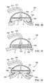
- a positioning device 40has an inner balloon 44 and an outer balloon 46 mounted on the distal end of a catheter 42 .
- the catheter 42is advanced into the tunnel of a PFO and the inner balloon 44 is then inflated until it engages the walls of the of tunnel, thereby centering the device in the tunnel.
- the outer balloon 46may then be inflated with contrast media and holes 48 in the outer balloon allow contrast media to weep out 50 .
- Hole geometrymay be varied to provide appropriate contrast flow rates. This may be observed under fluoroscopy and therefore the tissue defect anatomy and dimensions can be estimated including tunnel length, as well as allowing verification that the device is properly positioned.
- a closure deviceis then introduced over the positioning catheter to the defect and a closure treatment is applied. Visualizing the contrast media also helps to verify that the closure device is properly positioned with respect to the defect prior to treatment.
- FIGS. 9 and 9 A- 9 DAnother embodiment of a mechanical expansion device used for positioning is shown in FIGS. 9 and 9 A- 9 D.
- a closure system 60is illustrated having a catheter 62 with mechanical positioning elements 66 in the collapsed position, mounted on the distal end of the catheter 62 .
- the catheter 62 and positioning elements 66are advanced into the tunnel T of the PFO and then the mechanical elements 66 are expanded until they engage the defect walls and the device is positioned as illustrated in FIG. 9A .
- a closure device 64 also disposed on the catheter 62is therefore also simultaneously positioned against the tissue defect and then a treatment can be applied to close the PFO defect.
- FIG. 9Ashows the closure system when the mechanical elements 66 are expanded and engaged with the PFO tunnel, T.
- FIGS. 9B-9Dillustrate how the mechanical expansion elements 66 function.
- the mechanical elements 66are unexpanded and remain in a low profile position against the catheter 62 .
- the mechanical expansion members 66flex and bow outward to various diameters depending on how far the catheter 62 is actuated.
- FIG. 9Cfour expansion members are illustrated, although more or less may be employed, as shown in FIG. 9D where two members are shown.
- the expansion membersmay be fabricated from polymers or metals having a spring temper or superelastic alloys such as nitinol.
- FIGS. 10A and 10BAnother mechanical expansion embodiment is shown in FIGS. 10A and 10B .
- a positioning device 70comprises a catheter 72 which is introduced into the tunnel T of the PFO defect. Expansion members 74 are then expanded thereby properly positioning the device within the tunnel.
- the expansion elements 74are retractable into openings 76 in the catheter. The expansion elements 74 are actuated directly to control their expansion, and when unexpanded, have an even lower profile than the embodiment of FIG. 9C .
- a positioning device 80may include single or multiple flexible members 84 with both ends fixed to an elongate member such as a catheter 82 .
- a part of the catheter shaft 85may act as a core member between the flexible members 84 to further add rigidity to the positioning device 80 to assist with its pushability toward and through a tissue defect.
- the positioning device 80may be deployed through a closure device, or through a separate introducer catheter that is then removed, leaving the positioning device in place.
- Radiopaque markers 86 or coatingsmay be placed on various segments of the flexible members 84 to allow the user to view the orientation and spacing of the flexible members 84 and correlate them to the defect anatomy.
- markersmay be useful on the widest point of the flexible members to show the width of the PFO frown or opening, F, and may also continue along the length of the flexible members to help delineate the tunnel T (e.g. see the angle, show tunnel width, etc.).
- At least a portion of the flexible membersare preferably placed between the tissue of the PFO with the main catheter 82 extending into or through the defect tunnel.
- the flexible members 84extend laterally from the main body of the catheter to provide definition of the outer edges of the PFO, transitioning to define the location (angle) and size or width of the defect tunnel.
- the radiopaque markers 86 in FIG. 11are visible under fluoroscopy and permit orientation of the defect and location of the frown or opening to be discerned based on observation of the geometry of the flexible members placed within the defect.
- FIG. 12shows how a treatment device may be used with a positioning device.
- a closure treatment catheter 90has an elongate shaft 92 and a housing 100 on the distal end.
- a treatment region 96is disposed within the housing 100 and radiopaque markers 98 outline the treatment area 96 .
- a positioning device 94is advanced to a layered tissue defect such as a PFO until the distal end 104 extends beyond the defect.
- Flexible elongate members 106delineate the tunnel of the PFO and radiopaque markers 102 allow the physician to see the defect under fluoroscopy.
- the closure treatment catheter 90is then advanced over the positioning device 94 until the radiopaque markers of treatment region 98 are aligned with the radiopaque markers 102 of the positioning device and it is clear that the treatment catheter 90 is positioned over the defect properly for treatment.
- the positioning device 94may then be removed and a closure treatment can then be applied to the defect to close the layered tissue defect. If the treatment device 90 is placed directly over the positioning device 94 , the positioning device 94 is preferably constructed so that it can be removed with the treatment device 90 left in place. For example, in this embodiment, it is preferable that the flexible elongate members 106 can be pulled back through a lumen of the treatment device 90 .
- FIG. 12Ashows a crossing catheter similar to the embodiment described in FIG. 12 above.
- the crossing catheter 1300is also used with a positioning device.
- the crossing catheter 1300has an elongate shaft 1310 and a housing 1308 on the distal end of the shaft.
- An inner lumen shown by dotted linesis axially disposed within the crossing catheter elongate shaft 1310 and has an exit port 1312 in the housing.
- the crossing catheter 1300is used with a positioning device 1314 that is advanced to the layered tissue defect (such as a PFO) until the distal end 1304 extends over the defect.
- the positioning device 1314has flexible elongate members 1306 that mark the boundaries of the tissue defect.
- the flexible elongate members 1306indicate the tunnel of the PFO and radiopaque markers 1302 permit a physician to observe the defect under fluoroscopy.
- the crossing catheter 1300is then advanced over the positioning device 1314 until the housing 1308 is disposed over the tissue defect as indicated by the radiopaque markers.
- a vacuummay then be applied to the crossing catheter, either via the inner lumen or another lumen so that the housing 1308 is apposed with the tissue defect.
- the positioning device 1314may be removed and a treatment device, or a guidewire over which a treatment device may be delivered, may be advanced axially along the catheter elongate shaft 1310 through the inner lumen or another lumen until the distal end of the treatment device exits the inner lumen port 1312 .
- the inner lumen portmay be curved laterally such that, in the case of placing a guidewire, the guidewire exits the inner lumen at an angle sufficient to direct the guidewire transeptally, or through the tissue of the layered defect (for example from right atrium to left atrium either through the primum, through the secundum or through both tissue structures as depicted in FIG. 38B hereinbelow).
- a closure cathetermay be passed over the guidewire such that it may be deployed across the atrial septum at a point that is substantially centered, or positioned to close the PFO.
- “centered” or “positioned”may be descriptors of how the crossing catheter is optimally positioned to guide a transeptal puncture device in order to position a separate treatment catheter at the position on or over the tissue defect such that when a closure device is deployed, it substantially closes the defect.
- FIG. 13shows a cross-sectional view of a portion 114 of a positioning device 110 in a PFO tunnel.
- a portion of the positioning device 110extends past the tunnel exit 116 , while the proximal end of the device is outside of the tunnel, 112 .
- FIG. 14shows another embodiment of a positioning device.
- Positioning device 120represents a guidewire with whiskers 126 at the distal end to seat the wire device through a PFO and also to assist in sizing the width and locating the tunnel entrance or mouth F.
- the whiskers 126may be fabricated from a pre-formed resilient material (e.g.
- the whiskers 126deploy outwardly to seat within the corners of the PFO tunnel T.
- the closure devicecan be tracked over the guidewire 122 .
- the closure devicemay include radiopaque markers that can be aligned with guidewire markers (not shown) to seat over the outer limits of the width of the PFO and to include the tunnel entrance. Once in place the guidewire can be removed through the guidewire lumen in the closure device. In the case of the whisker wire, the whiskers would flex upwards to be in line with the main wire and all be pulled out through the guidewire lumen.
- the whisker elementsmay be spring loaded to ensure that they extend out to the farthest width of the defect that they are measuring or positioning. It is also within the scope of the invention that the guidewire device may be a separate catheter and while it provides a visual docking target, the closure catheter and the guidewire/positioning catheter are not physically linked, but are placed separately from each other.
- FIGS. 15A-15Dshows one embodiment of the whiskers positioning device discussed above with respect to FIG. 14 .
- a positioning device 130has a sheath housing 136 with slits 138 .
- a positioning catheter 132lies in the sheath 136 and positioning whiskers 134 also remain covered by the sheath 136 .
- the whiskers 134may be released from the sheath 136 , and the whiskers then expand through the slits 138 in the sheath 136 , as shown in FIG. 15B .
- the whiskers 134spring to a fully deployed position thereby properly positioning the device 130 and allowing PFO sizing, shown in FIG. 15C .
- the whiskers 134may be retracted into the sheath 136 which is illustrated in FIG. 15D .
- a looped wire designis employed.
- a looped guidewire type of positioneris used to position the device.
- a closure device 140has an elongated catheter shaft 142 and a distal housing 150 .
- a treatment region 144is disposed on the housing 150 along with placement wire apertures 146 and a guidewire aperture 148 .
- the looped guidewire in FIG. 16B with high flexibilityis retractable into apertures 146 and can be extended into the defect in a looped configuration to form a sizing and positioning device, as well as serving as a rail over which closure device can be placed accurately at a treatment site.
- FIG. 16Aa closure device 140 has an elongated catheter shaft 142 and a distal housing 150 .
- a treatment region 144is disposed on the housing 150 along with placement wire apertures 146 and a guidewire aperture 148 .
- the looped guidewire in FIG. 16B with high flexibilityis retractable into apertures 146 and can be extended into the defect in
- FIG. 16Cshows how the looped wire 154 is advanced until it engages the walls of the layered tissue defect.
- a guidewire 148may also be used to help deliver the closure device 140 to the tissue defect, and it exits out of aperture 148 .
- FIG. 16Dshows how the guidewire 152 and looped wire 154 fit into a PFO tunnel T and position the closure device housing 150 over the entrance of the defect, F.
- the looped wire 154may be designed with variable stiffness along its length to facilitate sizing and positioning.
- the looped wire 154shown in a straightened out configuration in FIG. 16E may have a stiff section 156 for accommodating the widest PFOs, a less stiff section 158 adjacent to the stiffest section 156 and a flexible section 159 in the middle of the loop wire.
- a closure device 170has a retractable catheter shaft 175 with a housing 176 attached to the catheter shaft 175 .
- the housing 176has a treatment region 174 on the housing and extensible positioning rails 178 serve as feelers to help stabilize the treatment device 170 .
- the housing 176 and positioning rails 178are retractable into sheath 172 .
- the housing shapemay be modified to include an extended nose 179 as seen in FIG. 17B . This shape helps position the closure device 170 against the tissue defect.
- a moveable guidewire lumen(not shown) may also be used to facilitate placement and sizing.
- a compound bendcan also help the closure device to be properly positioned adjacent to a tissue defect as shown in FIG. 18A .
- FIG. 18Aseveral bends 194 , 196 in the shaft 192 of a closure device 190 help to properly position the treatment portion of the device 190 against the tissue defect.
- typical ranges for the first bend indicated by angle ⁇is up to 75° while a second bend indicated by angles ⁇ and ⁇ are up to 60° and 75° respectively.
- FIG. 18Bshows a back view of the of the treatment device shaft where angles ⁇ and ⁇ both typically can range up to positions that encompass a range up to 80°.
- a wire sizing, positioning and treatment devicemay also include an electrode or multiple electrodes for applying energy to the defect while it is in position or near the position to close the defect.
- the electrodemay be formed or treated to be radiopaque to assist in sizing of the defect.
- Wireforms the bipolar electrode configurations, and sizes, orients and applies energy to close the defect.
- a wire sizing, positioning and treatment device 210is placed in a PFO. Wires 218 and 220 position the device 210 within the tunnel, and also serve as electrodes.
- a radiopaque marker band 214may be employed to indicate device position and vacuum lumens 216 may also be employed to allow the treatment device to approximate the defect surfaces prior to, during or following the application of sealing energy.
- FIG. 19Bshows a design where the electrodes 234 , 236 are modified on positioning, sizing and treatment device 230 with tips 238 that help the device to be removed after application of energy without disturbing the weld created.
- an exemplary catheter device 250which may be modified according to the present invention for treating an anatomic tissue defect includes an elongate catheter shaft 260 having a proximal end 264 and a distal end 266 , a sheath 256 (or “sleeve”) optionally disposed over at least part of shaft 260 , a handle 268 coupled with a proximal end of sheath 256 , and a housing 262 coupled with catheter shaft distal end 266 .
- a guidewire 280is passed through catheter 250 from the proximal end through the distal end.
- catheter body proximal end 264includes an electrical coupling arm 282 , a guidewire port 284 in communication with a guidewire lumen (not shown), a fluid infusion arm 286 in fluid communication with the guidewire lumen, a suction arm 289 including a suction port 294 , a fluid drip port 288 , and a valve switch 290 for turning suction on and off.
- Fluid drip port 288allows fluid to be passed into a suction lumen to clear the lumen, while the suction is turned off.
- a flush port with stopcock valve 298is coupled with sheath 256 .
- Flush port and stopcock valve 298allows fluid to be introduced between sheath 256 and catheter body 260 , to flush that area.
- sheath 256has a hemostasis valve 296 for preventing backflow of blood or other fluids.
- the distal tip of the sheathalso has a soft tip 258 for facilitating entry and release of the catheter housing 262 during delivery.
- the catheter device 250also includes a collapsing introducer 300 partially disposed in handle 268 .
- the collapsing introducerfacilitates expansion and compression of the catheter housing 262 into the introducer sheath 256 .
- the catheter housing 262may be inserted into introducer sheath 256 and then removed, thereby allowing the introducer sheath 256 to accommodate a larger housing 262 without having to simultaneously accommodate the collapsing introducer 300 as well.
- the collapsing introducer 300also has a side port for fluid flushing 302 and a valve (not shown) prevents fluid backflow. Locking screw 292 disposed in the handle 268 may be tightened to control the amount of catheter shaft 260 movement.
- an energy supply 254is connected to the catheter via the electrical coupling arm 282 and a controller 252 such as a computer is used to control energy delivery. In operation, it may also be possible to de-couple the handle from the device if desired, or to remove the handle altogether.
- FIG. 21illustrates the treatment catheter device 350 only.
- the treatment catheter 350has an elongate catheter shaft 366 having a distal end 354 .
- a housing 352 on the distal end of the catheter shaft 354delivers a treatment to a layered tissue defect to close the defect.
- the catheter shaft 366is axially aligned with a handle 372 and exits at a proximal end of the device and is sealed with a hemostasis valve 378 to prevent fluid backflow.
- An energy connector 380 and flush port 379are also disposed on the proximal catheter end along with a vacuum port 376 with additional port 377 .
- a screw 374tightens the catheter shaft 366 within the handle 372 to minimize motion between the two.
- a collapsing introducer tube 368 with soft tip 364 and flush port 370is also disposed partially in the handle 372 and is used to collapse the housing 352 and introduce it into an introducer sheath 358 .
- the introducer sheath 358also has a soft tip 356 which helps to accommodate and collapse the housing 352 when it is being withdrawn back into the introducer sheath 358 for removal from the body.
- a radiopaque markermay also be placed near the soft tip 356 to assist in visualization during a treatment procedure using fluoroscopy.
- Both the collapsing introducer 368 and the introducer sheath 358have side ports 370 , 362 for flushing. Valves in the collapsing introducer (not shown) as well as a hemostasis valve in the introducer sheath 360 prevent blood or other fluids from backflowing.
- FIG. 22Ashows the introducer sheath preferably used in the closure treatment system of FIG. 20 .
- introducer sheath 400has an elongated shaft 404 which is used to introduce the closure treatment device into the human body.
- the introducer sheath 400 in FIG. 22Ais shown as an elongated sheath, however the sheath may be angled or bent in different directions to assist with placement of the closure treatment device.
- the introducer sheath 400has a soft distal tip 402 and may include a radiopaque marker, which helps to accommodate the larger size distal end of a treatment catheter and collapse it into the sheath during removal as well as facilitate visualization under fluoroscopy.
- FIG. 22Billustrates one embodiment of the hemostasis valve, where two silicone disks 416 are used to create the hemostasis valve membrane 414 .
- the silicone disk 416is then scored partially through the top surface and also partially through the bottom surface, but not all the way through the disk.
- Two score linesare created 418 , 419 transverse to one another. At the intersection of the score lines 417 , the silicone disk is punctured all the way through.
- the silicone diskis approximately 0.352′′ in diameter and the slit widths can accommodate and seal over a 16 F shaft.
- Collapsing introducer 420has an elongate section 424 which can accommodate a distal treatment catheter housing. By collapsing the housing in the collapsing introducer, it can then be easily introduced into the introducer sheath previously described.
- the distal tip of the collapsing introduceris soft to help accommodate the larger size treatment catheter housing.
- the collapsing introducerhas a length approximately 6 inches and its soft tip is fabricated with Pebax polymer having a durometer of, for example, 35D while the elongate section 424 comprises, for example Pebax 72D durometer.
- the soft tipmay also be oval, crescent moon, or asymmetrically crescent shaped to facilitate collapsing the housing.
- the proximal end of the collapsing introducerhas a hemostasis valve 428 designed to accommodate the treatment catheter shaft as well as a flush port 426 .
- FIGS. 24A-24Eillustrate how the collapsing introducer works.
- a treatment catheter 450is inserted into the collapsing introducer 452 .
- the collapsing introducer 452is slidably moved towards the distal end of the treatment catheter 450 until the housing 460 is collapsed and enclosed by the collapsing introducer 452 .
- the treatment catheter 450 with its housing 460 collapsed in the collapsing introducer 452is then advanced and introduced into an introducer sheath 462 in FIG.
- the treatment catheter 450is advanced forward into the introducer sheath 462 until the housing 460 exits the introducer sheath 462 and resumes its shape.
- the treatment catheteris advanced to a layered tissue defect and a treatment is then applied. After the treatment is competed, the catheter housing 460 is pulled back into the introducer sheath 462 and the catheter 450 may be removed from the patient's body.
- catheter device 250may include additional features or fewer features.
- catheter body distal end 266may include lubricious liners or coatings on the device as well as heparin coatings for reducing thrombus.
- Different configurations for fluid delivery and vacuumare also possible.
- a controller built into the power generatorcan alleviate the need for a computer controller, except for displaying treatment parameters. Therefore, the following description of embodiments is intended to be primarily exemplary in nature and should not be interpreted to limit the scope of the invention as it is described in the claims.
- One aspect of a successful tissue weld of a defect to be treatedis the interface of the tissue at the therapeutic element (electrode, heating element, or mechanical closing mechanism). This interface may be impacted by the following variables, including any leaks in the housing, leaks or shunts in the anatomy (e.g. through the PFO), physical placement of the housing over the defect, deformation of housing against tissue interface and resulting housing volume, forces exerted by the housing, and the pressure used to appose the treatment site with the housing.
- Various embodimentsare presented that may assist in tissue apposition within or against the treatment element for closing a PFO or other layered tissue defect.
- closure catheter devicessuch as those detailed in the co-pending application Ser. Nos. 10/873,348; 10/952,492; and 11/049,791 may be enhanced by the following features.
- FIG. 25AA representative embodiment of a catheter housing 475 is shown in FIG. 25A .
- the housing 475is attached to a catheter shaft 477 and is formed from 60A durometer silicone because of its high tear strength and resistance to deformation at the temperatures employed to weld tissue. Other durometers may also be employed and in some cases a housing may be constructed of multiple durometer polymers in one device, or a polymer and a reinforcing element such as mesh or a filament.
- the housing 475has a primary shape 476 and a surface 479 adapted to appose the tissue defect.
- the housingmay still flatten or collapse 478 .
- skirt or flange of the housingcan flatten as well. This can lead to a shallower (shallower) housing volume within which tissue may be apposed. As such, certain features may be designed into the housing to define the optimum housing volume.
- Some features that provide a more resilient housing, and in turn allow greater tissue invagination upon vacuum activationinclude: reinforcing the roof of housing, taller housing, and reinforcements in flange or skirt of housing. As depicted below, areas of the housing may be selectively reinforced to aid in sealing the treatment area within the device housing.
- the “roof” of the housingmay be formed of a thicker material (preferred material is silicone and it would be molded, the mold cavity would be constructed to allow more material to flow into the reinforced region).
- the reinforced roofallows the housing to remain somewhat tented during vacuum apposition.
- a stiffening elementsuch as spring steel or nitinol may be used in thicknesses ranging from, for example between 0.002′′-0.005.
- Reinforcement in the roof regionmay also be achieved by molding a thicker region using the material of the housing, or adding material to the roof of the housing to make the reinforced area in the range of 0.005′′ to 0.025′′ thick, for example 0.010′′ thick while still accommodating vacuum channels as described in copending application Ser. No. 10/952,492, the full disclosure of which has previously been incorporated by reference, and allowing the housing to collapse.
- stiffening elements 492 or extensions 496may be employed in a similar manner (e.g. additional molded material or separate resilient extensions).
- additional molded material or separate resilient extensionse.g. additional molded material or separate resilient extensions.
- such extensions or reinforcementmay have a thickness of between 0.005′′ to 0.050′′ and between 1-3 mm in height.
- a semi-rigid ring 494may be incorporated into the bottom of the flange to give hoop strength to the flange, especially when vacuum is applied via a lumen 487 in the catheter shaft 486 connected with the housing 485 .
- a 1 mm ⁇ 1 mm square in cross-section of materialwas molded at the bottom of the flange.
- a nitinol ringwas used, allowing the thickness of the region to be about 0.010′′ or slightly smaller and not square in cross-section which allows for better collapsibility.
- a polymer O-ringmay be employed.
- Such additional housing material and reinforcement elementsmay be used alone or in combination with each other for the desired rigidity, while still allowing the housing to be collapsed within a guide catheter for deployment to and retrieval from the treatment site.
- the housing element 485may be adapted to appose the tissue and keep it in place while a fusing or fixation element is brought into contact to secure the tissue.
- the housing element 485may be activated (suction applied) and then a catheter device containing a clip or fixation element may be advanced to the treatment site, and applied to the apposed tissue.
- fixation elementsmay be clips such as those described in pending application Ser. No. 10/787,532, filed Feb. 25, 2004; and Ser. No. 10/811,228, and further U.S. application Ser.
- FIGS. 25C through 25Ishow a bottom view of the housing that apposes the tissue defect.
- a housing 1320has a boomerang shaped side 1322 with a nose extending from the triangular apex region that may provide better apposition with certain tissue defects.
- FIG. 25Dshows a triangular shaped side 1342 of the housing 1340 with apices radiused while FIG. 25E illustrates a kidney bean shaped side 1362 of the housing 1360 .
- FIG. 25Fshows a circular housing side 1382 while FIG.
- FIGS. 25Gdepicts a housing 1400 with a generally triangular shaped side 1402 but with the base and apex modified to include nose-like protrusions.
- FIGS. 25H and 25Ialso show variations on the triangular shaped side of the housing for tissue apposition. In the case where an electrode is used to close the layered tissue defect, the electrode shape may match the housing or it may be modified to best match the tissue defect.
- FIGS. 25C through 25Ishow various electrode embodiments that may be used.
- a cone shaped or domed housingcan provide greater tissue apposition, (optionally in combination with a “stepped” electrode as set forth in application Ser. No. 10/952,492, the full disclosure of which has previously been incorporated herein by reference).
- An example of the stepped electrode 504may be seen in housing 500 of FIG. 26 .
- the electrodemay alternatively be planar and optionally may be angled in the housing to accommodate tissue thickness variations. This is illustrated as electrode 530 in housing 525 of FIG. 27 .
- a hinged housingmay also provide better tissue apposition and defect closure by allowing the housing to better adapt to anatomical variations in the tissue defect.
- a treatment device 1450comprises an elongated catheter shaft 1454 with a housing 1452 adjacent to its distal end.
- the housinghas a hinge mechanism 1456 that allows the housing to articulate. When the housing articulates, its shape adjusts to better conform with the anatomy of the tissue defect.
- an apposition surface 1462is operatively coupled with the housing so that it too can better conform to the tissue defect anatomy.
- the apposition surface 1462may only comprise a surface for apposition or may additionally comprise a treatment region that can be used to close the layered tissue defect.
- vacuum ports 1458 and 1460may be located in the housing to assist the housing appose the tissue defect.
- vacuum ports 1458 and 1460are positioned within the housing so that they may help draw in the primum and secundum tissue layers for better apposition in a PFO defect.
- FIG. 26Bmultiple hinges 1484 are utilized in the housing 1486 of a treatment device 1480 .
- An elongate shaft 1482is connected to the housing 1486 and may be used to articulate the housing into different configurations with control rods or wires.
- the hingesmay also be adapted to permit flexing of the housing when it is pressed against a surface.
- An apposition surface 1488which generally takes the same form as apposition surface 1462 in FIG. 26A is also operatively connected to the housing 1486 so that its shape may be adjusted for better apposition with the tissue defect.
- FIG. 26Cillustrates how the hinged housing 1506 of a treatment device 1500 provides an alternative apposition surface 1508 .
- vacuum ports 1524 , 1526may be used in the housing 1522 of a closure device 1520 , as illustrated in FIG. 26D .
- vacuum ports 1524 around the circumference of the housing 1522are combined with a centrally placed vacuum port 1526 for enhanced apposition of the housing 1522 against the tissue defect.
- a screen or slotted membermay receive target tissue and oppose or “grip” the tissue during treatment.
- the screenmay also be an electrode (monopolar/bipolar).
- FIG. 28Aillustrates the primum P and secundum S tissue layers of a PFO being received into a screen upon application of vacuum through a lumen 556 in a catheter shaft 554 connected with the housing 552 .
- the screenis also an electrode with an electrical connector 560 running through a lumen 556 in the catheter shaft 554 .
- a cross-sectional view of the tissue 568 being received into a screen 564 having a receiving aperture 566is shown in FIG. 28B .
- FIG. 29Aillustrates another way in which tissue P, S can be captured by the screen 584 and FIG. 29B shows a cross-sectional view of the tissue P, S being received by an aperture 588 in the screen 590 .
- the screen 590may also serve as an electrode to weld the tissue layers together or a secondary electrode may be deployed later during the procedure for
- a recess in housing (or around skirt) 604may assist in opposing or gripping tissue once the tissue is brought into the housing 600 using a vacuum.
- the screen 606may be fixed to position tissue, or may be moveable as shown by the arrows in FIG. 30 . Movement is controlled by an elongate member 610 through a lumen 612 in the catheter shaft 608 to further clamp tissue P, S against the recess 604 , and the screen 606 may be an electrode. This embodiment is illustrated in FIG. 30 .
- a first screen 633may be employed together with a second screen 632 .
- the second screen 632is moveable between a first position and a second position as shown by arrows, or range of positions, relative to the first screen 633 and can be employed to trap the tissue P, S prior to treatment.
- such screens 632 , 633could also be the electrode(s) for applying energy to join the tissue flaps of the heart defect together. They may be monopolar (one screen is energized while the other is totally insulated), or bipolar (wherein both screens are energized to create a bipolar energy field to assist in tissue fusing.
- the housing 652may be actuated to further grip tissue with the recess feature 664 previously described above. Gripping action of the housing pivots the housing from one position 662 to a second position 664 and can be employed by actuatable struts (not shown) within housing material that extend from a pivot point at the apex of the housing, or by advancing a sheath (not shown) over the housing 652 to further collapse the structure on the tissue P, S.
- FIG. 32Aillustrates an alternative approach to apposing tissue.
- a moveable vacuum tube 671is advanced in order to appose tissue P, S. Once vacuum is applied and the tissue is engaged, the vacuum tube 671 may be pulled back into the housing 666 so that tissue is engaged against a screen 667 which can also serve as an electrode.
- FIG. 32Bshows that the vacuum tube 668 may have an optional vacuum screen 670 at its distal end to facilitate tissue engagement.
- a bipolar clamping device (electrode structure) 680may be integrated into the housing 676 , or advanced as a separate element to grasp and weld the tissues P, S of the heart defect together.
- the bipolar clamping element 680may be deployed distally of the catheter housing to grasp the defect to be treated and draw it back into the housing for treatment.
- clamping graspers 680may be employed separately or in conjunction with suction applied through a lumen 682 connected with the housing 676 .
- the graspers 680are controlled by an elongate member 684 through a lumen 682 in the catheter shaft 678 .
- the suctionoperates to maintain a seal in the treatment area, and the clamp 680 can operate to not only clamp the tissue, but also to keep the treatment catheter 675 positioned at the site of the defect.
- FIG. 34Ashows another embodiment where a ring electrode 712 may be employed in the housing 702 or around the flange of the housing ( 724 in FIG. 34B ) to seal tissue.
- a ring electrode 712in the housing 702 , it can either be fixed to the walls of the housing, or separate and deployable about the acquired tissue.
- FIG. 34Ashows the ring electrode 712 separate from the housing 708 . In some cases it may be desired to cinch the electrode from a larger diameter 710 to a smaller diameter 712 around the tissue P, S, such as a snare type device.
- the electrode structurecan provide additional rigidity to the flange region, thereby assisting with tissue apposition while also being activated to delivery energy and seal.
- the ring electrode in either configurationmay be the return electrode in a bipolar system as shown in FIG. 35 .
- a second active electrode 748may be inserted into the tissue to be treated P, S while a ring electrode 744 is disposed within the housing 742 and serves as the return electrode.
- FIG. 36shows an alternative embodiment where a second active electrode 768 is inserted into the treatment region P, S and a cinch or snare electrode 770 is the return electrode.
- an additional embodimentshows an apposition device 780 of the present invention which may include a mechanical device 784 deployed from the housing 782 , through the tissue or defect to be treated (see FIG. 38B ), and capable of pulling the tissue back into apposition with the housing 782 .
- a mechanical assistance device 784can be used alone or in conjunction with vacuum apposition.
- the apposition device 784would be very low profile in its “stowed” condition for placement through tissue of the defect or through the defect opening, and then deployed to an expanded condition as indicated by phantom lines, whereupon it may be drawn back toward the catheter housing 782 to tension the tissue between the catheter housing 782 (and electrode) and the expanded portion of the apposition device.
- FIG. 38AOne embodiment of this device shown in FIG. 38A includes a molly bolt type (or mallecott) apposition device 810 deployed through a needle 804 placed through defect or through defect tissues.
- the deviceis shown placed through tissue in FIG. 38B . Once placed through tissue, it is then expanded 808 to provide a backstop and hold tissue, and is illustrated in FIG. 38B .
- the apposition devicemay be a wire that expanded to a looped or “petal” type configuration 812 as shown in FIG. 38C and a side view in FIG. 38D .
- the apposition devicemay be deployed through the guidewire lumen of the treatment device, or through a separate, dedicated lumen. These devices may be positioned with respect to the defect to be treated by using the positioning devices of the present invention described previously.
- an apposition devicemay be deployed separately from the treatment device into the left atrium, remote from the treatment site, to “bookend” the defect against treatment catheter and thereby create enhanced tissue apposition.
- Such a separately deployed apposition devicewould preferably be low profile to allow the remote puncture site to heal naturally, without requiring a therapeutic intervention to close the puncture.
- FIGS. 39A-39Eillustrate this with respect to a PFO closure, but several other defects in the heart could be apposed and closed in a similar manner.
- a needle cannula 826is inserted from the right atrium to the left, remote from the defect opening.
- a tissue apposition device 828is then deployed into the left atrium toward the site of the defect or tissues to be apposed, as shown in FIG. 39B .
- a treatment catheter 832 and the left atrial apposition member 834are then brought into alignment at the site of the defect to be closed, which is illustrated in FIG. 39C .
- Forceis applied to assist in apposing the tissue closely within the housing 830 of the treatment device 832 , shown in FIG. 39E .
- the treatment device 832is removed and the apposition device 836 is retracted into the needle cannula 826 , after which time the needle cannula 826 is removed and nothing is left on the left atrial side of the heart.
- the needle cannula entry sitemay be left to close naturally and the layered tissue defect is also closed as seen in FIG. 39E .
- FIG. 39FAnother embodiment is shown in FIG. 39F where a needle like structure 843 is used to penetrate the tissue defect.
- An apposition member 842is then released from the needle structure 843 to provide a backstop.
- a pivot on the device 841can then be actuated, bringing the treatment housing 840 and backstop 842 together.
- the closure treatmentmay then be applied.
- the backstop 842may be retracted into the needle structure 843 , and both are withdrawn into a sheath 844 , and the entire device is removed from the patient or moved to another treatment location.
- FIGS. 39G-39Iillustrates another embodiment for enhanced apposition including a elongated guidewire 1530 with a flexible T-shaped distal end 1532 .
- the elongated guidewire 1530is placed through the PFO tunnel until the T-shaped end exits the tunnel on the left side of the heart.
- the flexible whiskers 1532 which form the T-shaped endare then free to expand outwardly and then can serve as an anchor point for the guidewire 1530 .
- FIG. 39Hthe elongated guidewire 1530 is retracted which results in the whiskers 1532 forcing the primum P against the secundum S, thereby reducing the gap therebetween and permitting better fusing of the two layers.
- a closure treatment device 1534is then delivered to the treatment site, here, delivery of the closure treatment device 1534 is advanced axially over the guidewire 1530 .
- the closure treatment device 1534then applies a treatment to the tissue defect, partially closing the defect, except for the region where the guidewire 1530 rests.
- the guidewire 1530is removed from the tunnel and the closure device 1534 may complete the treatment by sealing the PFO and fusing the primum P and secundum S together 1538 .
- FIGS. 40-42Another approach to applying the required tissue compression prior to defect closure utilizes magnetic attraction as shown in FIGS. 40-42 .
- a compressive forcecan be applied without requiring a physical link between the sides of the tissue.
- Any combination of ferromagnetic material, magnet material, and/or electromagnetic materialcan be used to create the desired force.
- rare earth permanent magnetssuch as Samarium Cobalt (SmCo) or Iron-Neodymium (NdFeB) provide substantial levels of magnetic flux for a given volume of material and are implantable grade materials.
- Coupling such a magnet with a ferromagnetic counterpartcan simplify the use of magnetic attraction to create force because orientation of the ferromagnetic portion of the coupling does not require a specific orientation relative to the permanent magnet in order to create an attractive force. Further, use of an electromagnet can be beneficial since it can be selectively activated (turned on and off).
- magnet and/or ferromagnetic components used for such an applicationcan be in singular elements, or an array of smaller elements that may be more easily delivered to a remote location through a patients vasculature.
- magnetic components 856may be coated or formed for implant in a human body, loaded into a catheter 852 as shown in FIG. 40 .
- the assembly 850may be delivered to relevant locations while contained, and then released at the desired location with respect to the defect to be treated, and deployed.
- magnetic elements 862 , 864are placed on either side of a PFO (one in the right atrium and one in the left atrium).
- An energy treatment catheter 866is placed between the magnets 862 , 864 in the right atrium to deliver the tissue welding treatment once the tissue or brought together by the magnetic force.
- the magnet on the right atrium 862could be incorporated into the energy treatment catheter.
- the magnetic device deployed in the left atrium 864could be placed with a similar needle catheter delivered remote from the defect to be treated, and once magnetic apposition was achieved and the defect closed, the left side magnetic 864 component would be removed.
- the magnetic coupler 875would have a first magnetic element 876 placed on the left side of the defect, and a second magnetic element 878 placed on the right side of the defect.
- One or more inflatable balloonsmay be used as deployment tools, for example to separate each magnetic element until proper positioning is obtained. Once each element is properly placed, the balloon can be deflated and removed, leaving the magnetic coupling elements in place, and able to attract each other to seal the defect.
- the ability to appose tissue and create a treatment area conducive to welding tissuemay be enhanced by the application of negative pressure, i.e. vacuum, at the treatment site.
- negative pressurei.e. vacuum
- Certain features of the housingmay be constructed to assist in creating a robust seal at the tissue interface, and maintaining that seal for the duration of the treatment.
- tissue appositione.g. a more resilient housing
- the following featuresmay be incorporated into the housing flange.
- Additional “grippers” or protrusions 894 in the rim of housing 892increase tissue apposition to the device 890 .
- An additional vacuum lumen 896 in the housing rim 892may also be useful to distribute the vacuum force toward the outer edge of the housing at the housing/tissue interface. This is illustrated in FIG. 43 .
- gusset 904may be added to the housing 902 to increase the sealing force of the flange, but still keep the housing flexible. Gussets 924 may be placed circumferentially around the outer housing flange 922 at various locations, and this is seen in FIG. 44B .
- FIGS. 45A-45Cshow a preferred embodiment of the housing 940 .
- FIG. 45Aillustrates a top view of the housing which preferably has a flange or skirt 942 having a diameter of 0.921 inches and the housing itself has a diameter 944 of 0.730 inches.
- An elongate member 950represents the transition from the housing 940 to a catheter shaft.
- the housinghas a slightly tapered profile when observed from the side in FIG. 45B .
- the distal tip of the housing 946is the lowest point of the taper, and preferably has a height of 0.140 inches while the proximal end of the housing 948 is higher and is preferably 0.297 inches high.
- a front view of the housingis seen in FIG. 45C and this view shows the flange or skirt 942 connected to the housing 944 .
- FIGS. 45D-45FAnother embodiment of the housing is illustrated in FIGS. 45D-45F .
- FIG. 45Da top view of the housing 1550 is shown.
- the housing 1550here has a nose-like front projection 1552 and a rectangular-shaped 1554 rear projection.
- the housingis typically attached to an elongate catheter shaft 1556 .
- Both projections 1552 and 1554form a skirt around the housing 1550 , attached along the housing rim 1558 , and that helps the housing to match the tissue defect anatomy and appose the defect.
- FIG. 45Eis a side-view of housing 1550 showing the skirt 1564 and a domed housing top 1562 .
- a front view of the housing 1550is shown in FIG. 45F which illustrates the skirt 1552 attached with the housing rim 1558 .
- InfusateSuccessful welds of heart defects may be achieved in the presence of infusate or drip fluids into the treatment region, as described in application Ser. No. 10/952,492, the full disclosure of which has previously been incorporated herein by reference, to mediate the moisture content of the treatment area and maintain patency of the catheter lumens.
- Infusateis used primarily to prevent blood from stagnating within a treatment device distal housing and thereby clotting. By providing constant infusate flow, stagnation is avoided. Heparin can also be added to the infusate to further minimize clotting.
- welds of heart defectshave also been achieved with relatively “dry” tissue (low or little infusate).
- infusatein the event that the use of an infusate is desired, the following variables may affect the efficacy of the tissue weld, namely, type of infusate (saline, D5W (Dextrose 5% and water) or G5W (Glucose 5% and water), rate of infusion, flow distribution at tissue interface (pattern, consistency), temperature of infusate and the like.
- infusionmay be used in the following range 0-30 ml/min, and more particularly in the range of 1-10 ml/min.
- the infusateis then aspirated from the treatment site via the vacuum lumen.
- the vacuum suctioncreates a continuous draw of flush through the infusion lumen, passing through the distal housing, and back out the vacuum lumen, for example a passive or “closed loop” infusion.
- the infusateis then collected in a vacuum canister.
- Adequate vacuum sealcan be determined by observation of the distal housing under fluoroscopy (lack of movement, “flattening” as determined by imaging of fluoroscopic markers or echogenicity of housing), and observation of the color of the fluid suctioned to the vacuum canister (e.g.
- an example of a substantial seal that may still include an “acceptable leak rate”is in the range of 0-150 ml/min, for example, in the range of 1-30 ml/min. This leak may be attributable to physiologic phenomena, as well as mechanical issues with the housing seal against the tissue.
- Electrode Design and Energy AlgorithmVarious parameters can be controlled to achieve the most advantageous result in closing a PFO or other defect in the heart with energy. As discussed above, greater tissue apposition can function to increase the likelihood of consistently welding the PFO tissues (primum and secundum), in a clinically acceptable procedure time. In addition to greater tissue apposition, various parameters related to the power algorithm can be controlled and optimized. Certain parameters include developing a feedback loop to ensure enough power is delivered to achieve the desired closure (plane of welding), that the power delivery does not lead to unwanted “pops,” that the power delivery does not lead to impedance spikes of the kind that prohibit additional power delivery to tissue within the specified procedure time, and the like. Others include design of the electrode, including the size, thickness and other physical features that effect energy delivery. The treatment device and the power system of the present invention are depicted in FIG. 20 where the power supply 254 hooks into port 282 with a standard medical electrical connector.
- Electrode DesignThe configuration of the electrode may play a role in optimum energy delivery. Certain features of an electrode or heating element that may affect closure (welding) include, element density, geometry, size, current density, surface features (gold plating for radiopacity, coatings, electropolishing of conductive surfaces), location of the power connection, and points of insulation on the element.
- a larger electrodealthough able to treat a greater area of tissue, requires more power and therefore is less efficient, and may lead to additional conduction in the tissue to areas of the heart that the procedure is not intended to effect.
- An electrode design that is matched (size, capacity) to provide “localized energy density” to the intended treatment regioncan function to limit the power required to achieve the intended result, and therefore a more efficient, safer lesion is created.
- a banded electrode 964may be adapted to concentrate the power delivery at the point over which the defect comes together. This band can either be created by cutting an electrode pattern that is in the desired shape or masking a larger electrode such that only the desired band of active electrode is exposed.
- banded electrode 964is cut into a rectangular shaped piece with a guidewire exit port 966 running through the electrode 964 .
- Various other portions around the electrode and housingare insulated 962 so that energy is only delivered over the banded electrode 964 .
- openings within the electrode 972allow vacuum to be applied for tissue apposition and struts 970 connect the electrode 964 to the housing 968 and help provide support.
- FIG. 48shows an alternative embodiment of the banded electrode 1028 wherein the active electrode band pattern has been cut into the desired shape, here an undulating wave-like pattern. Additional features such as an exit port for a guidewire 1032 , vacuum ports 1030 , a thermocouple 1026 , insulated struts 1024 for support and a housing flange 1022 have previously been discussed.
- FIGS. 47 and 49employ the masking embodiment.
- portions of the electrodeare masked 996 so that energy is only delivered via an active region 999 .
- Other featuressuch as vacuum ports 994 , support struts 998 are also utilized.
- FIG. 49shows a variation of masking, where portion of the undulating wave-like pattern previously discussed above are masked to control energy delivery.
- masking 1044controls where the active electrode region is. Typical electrode measurements are in the range of 30 mm wide by 20 mm tall, for example 15 mm wide by 9 mm tall. The total area of the electrode may vary depending on the chosen geometry.
- Electrodesmay be configured in a variety of shapes, including elliptical, circular, rectangular, triangular, or have geometries that are a combination of those approximate shapes in order to best fit the geometry of the tissue to be treated.
- An alternative electrode embodimentis illustrated in FIG. 49A .
- a housing 1570is disposed on distal end of an elongate catheter shaft 1576 .
- the housing 1570has a nose-like protrusion 1572 and a rectangular shaped rear protrusion 1574 .
- the nose-like protrusion 1573may also be moved closer to the electrode 1586 , as shown by dotted line 1573 , in order to better appose the tissue.
- a partially oval shaped electrode 1586is disposed in the housing 1570 and a guidewire lumen 1578 port 1580 exits through the electrode 1586 .
- the electrode 1586is adapted to more accurately match PFO anatomy. In the case of a PFO, the electrode is adapted to treat PFOs ranging in size from 1 mm to 30 mm and more typically in the range from 3 mm to 26 mm.
- Maskingmay be applied by spraying or dip coating and typically employs a silicone layer, although other methods and materials are well known in the art.
- the openingmay be round, oval or other shapes, such as a crescent, to mimic the defect to be treated. Illustrative embodiments of this are shown in FIGS. 50A and 50B .
- FIG. 50Ashows a variable mask wherein the inner diameter 1056 can be controlled, while in FIG. 50B an elliptically shaped aperture 1074 is controllable.
- a treatment catheter 1090may be formed by using coaxial shafts 1092 , 1094 that allow relative axial rotation to twist an elastomeric tube 1096 or otherwise create a valved effect (similar to an iris valve). Final mask shape is then achieved by rotating one shaft relative to the other until the desired mask shape is reached. The two shafts can then be locked together to prevent the shape of the mask from changing during treatment.
- a mesh electrode 1097is shown in FIG. 51A , and may be employed, having an insulation coating 1098 or sleeve.
- tissuewould be drawn into the cavity created by the electrode and energy delivered.
- the insulating sleevemay be withdrawn, exposing the desired amount of active electrode.
- FIG. 52Aillustrates a further embodiment of an electrode having lobes or “petals” 1104 which may be employed to the desired size, either by using separate loops, or feeding out a length of preformed nitinol wire to achieve the desired configuration.
- an electrodesuch as this can be deployed once a seal by the catheter housing 1102 has been obtained, it is possible for the user to apply a certain amount of directional force with the electrode against the tissue, which may be useful in creating optimal tissue apposition with the target, on its own, or in conjunction with other apposition devices and techniques disclosed herein.
- a bottom view of the housing 1102 emphasizing the petals 1104is seen in FIG. 52B .
- the active electrodemay be an alternating current bipolar electrode (requiring less energy, and in a more localized manner), and configured as either an electrode commensurate with the size of the housing, or less than the size of the housing, by masking, otherwise insulating, or cutting the electrode to a smaller size.
- Interdigitating active 1122 and return 1124 electrodescan be laid out on a planar electrode substrate. Alternating active 1142 and return 1144 electrodes across a planar electrode substrate may also be employed as seen in FIG. 54 .
- each half of the magnetic couple 1162 , 1164could be one pole of a bipolar RF circuit.
- only one of the portions of the magnetic couple 1184is used as part of a monopolar RF circuit and this is illustrated in FIG. 56 .
- Further combinations that include either one or more of the components of the magnetic couple in either a monopolar or bipolar RF circuitare also possible. It is within the scope of the present invention to also size, mask or otherwise modify the electrode configurations described in co-pending application Ser. No. 10/952,492, previously incorporated herein by reference.
- FIG. 57A preferred electrode embodiment is shown in FIG. 57 .
- An electrode 1200is illustrated prior to attachment with a catheter housing.
- struts 1204 , 1206 , 1208 extending from the electrodeare designed for attachment to the housing in order to connect the structures with one another.
- Struts 1204 , 1206 and 1208also serve to provide support for the housing.
- Barbs 1202may be employed on the struts 1204 and 1208 to help attach them to the housing.
- a monopolar electrodeis formed from a series of parallel bars 1222 separated by a slit 1224 .
- a set of bars 1222is separated from an adjacent set of bars by another gap 1218 .
- An outer perimeteris formed by a ring 1216 and apertures 1226 allow vacuum to be applied as well as administration of an irrigation fluid.
- Tabs 1210 , 1211 and 1212allow a piece of tubing to be attached to the electrode to facilitate guidewire entry and exit from the housing.
- the electrodehas a thickness of approximately 0.0029 inches and struts 1204 , 1206 and 1208 are typically about 0.020 inches wide by 0.004 inches thick.
- Ring 1216 widthis about 0.012 inches, while the bar 1222 width is approximately 0.040 inches and slits 1224 are about 0.012 inches with gaps 1218 being about 0.030 inches wide.
- the slits in this embodimentallow suction to be applied through the electrode, help to minimize tissue from adhering to the electrode surface and create an edge from which RF energy is delivered to tissue.
- FIG. 57AA floating electrode embodiment is illustrated in FIG. 57A .
- an electrode 1600unattached with a catheter housing is shown.
- Struts 1604 , 1606 and 1608are connected with the housing and help to provide support to the housing during tissue apposition and/or vacuum application.
- Barbs 1602 on the struts 1604 and 1608also help to connect the struts 1604 and 1608 to the catheter housing.
- a parallel series of bars 1622is separated by a slit 1624 therebetween, forming a monopolar electrode.
- Each set of parallel bars 1622is separated from an adjacent set off bars by another gap 1618 and an outer perimeter is formed by a ring 1616 .
- the electrode bars 1622connect with the perimeter 1616 via a flexible elastomeric coupling 1628 such as silicone.
- the flexible couplings 1628allow the electrode to float and therefore the electrode can adapt to various tissue defect anatomies more effectively by compensating for changes in tissue thickness or height.
- the electrode bars 1622are hinged 1630 , allowing further adjustability of the electrode surface to accommodate are more diverse range of tissue anatomies.
- Other aspects of this electrode embodimentinclude apertures 1626 within the electrode which allow vacuum to applied as well as administration of irrigation fluid.
- Tabs 1610 and 1612allow tubing to be attached to the electrode to facilitate guidewire entry and exit from the housing. Electrode dimensions generally take the same form as the electrode described in FIG. 57 above.
- FIG. 58Ashows the electrode of FIG. 57 mounted in a catheter housing 1260 .
- the housing 1260has a flange 1256 . Struts are embedded in the housing and therefore, only the electrode 1254 is exposed.
- An aperture for a guidewireis more clearly visible in FIG. 58A and is represented by 1258 .
- FIG. 58Cillustrates a piece of tubing 1262 used to transition from the guidewire aperture 1258 into the guidewire lumen of the catheter shaft 1252 in FIG. 58A .
- the tubingis a length polymer tube with two apertures adapted to be placed over tabs 1210 and 1212 in FIG. 57 to secure the tubing to the electrode.
- Tab 1212may also be bent at an angle to further facilitate guidewire entry and exit from the guidewire aperture 1258 .
- FIG. 58Bhighlights the two apertures on the tubing.
- this tubingis approximately 0.044 inch outer diameter ⁇ 0.039 inch inner diameter polyimide with a length about 39 inches.
- the long aperture 1264is approximately 0.687 inches from the distal tip of the tubing and has a width of about 0.033 inches by 0.134 inches long and a radius approximately 0.017 inches.
- the smaller aperture 1266is approximately 0.038 inches by 0.028 inches.
- the electrodes of such a devicecan be designed to allow electrophysiology monitoring of the heart. Such mapping would permit a physician to determine if the treatment device is too close to sensitive areas of the heart, such as the AV node. Additionally, monitoring could be used to ensure that during treatment, aberrant conductive pathways were not being created. Mapping also allows power delivery to be controlled so that minimal required power is delivered and also permits the active surface of the electrode to be controlled and minimized so that treatment energy is not applied to an area greater than necessary.
- two small circular electrode pairs 1654may be placed on and insulated from the electrode 1656 or housing 1652 and can serve as bipolar mapping electrodes.
- the electrodesmay take a number of configurations such as two pairs side by side in FIG. 58D or in a linear arrangement 1684 as shown in FIG. 58E .
- These electrodes 1694may be 0.5 mm to 2 mm in diameter as shown in FIG. 58F , and can be fabricated from stainless steel although platinum or platinum-iridium are preferable as well as nitinol.
- Cardiac electrophysiology mappingis well known in the art and is well documented in the medical and scientific literature. Exemplary products are manufactured by Boston Scientific.
- the following welding algorithmsmay be successfully employed to achieve closure or sealing of the PFO tissues using a range of parameters that utilize feedback to vary the time and power applied to achieve a tissue weld.
- the algorithmwould start at a low power (e.g. 1-10 Watts to 20-50 Watts) and gradually increase over time. This allows the controller to evaluate how the defect is responding to the application of energy.
- the objective of the algorithmis to deliver the maximum amount of power during a desired duration, while not over-treating the tissue.
- a software controller systemmay be employed to ramp the power over the designated time and to respond to the impedance readings or other user or manufacturer designated feedback or settings.
- FIG. 59A schematic depiction of the power supply is depicted in FIG. 59 .
- the power supplyis connected to the treatment device and a return electrode is connected to the generator.
- a variety of feedback inputsmay also be connected to the power supply or CPU, including thermocouples, electrodes for sensing impedance and the like.
- a software controller systemutilizing a CPU can be employed to adjust the power over the designated time and to respond to the impedance readings (e.g. shut off/restart/restart at lower or higher power as directed by the input algorithm).
- This systemmay be further linked to a computer (laptop) or other user interface for purposes of graphical interface and data collection.
- energymay be applied with an initial power setting of 20 Watts, and the power increased every 30 seconds by 5 Watts until 40 Watts is reached (“power ramp”). Following this initial ramp, energy may be applied until either 1) a total run time of 10 minutes is reached, or 2) an impedance spike occurs. If the total run time reaches 10 minutes the application of power is considered complete for purposes of this example. If an impedance spike is reached, an additional power ramp is reapplied until a total of five spikes have occurred or until a subsequent spike occurs after a cumulative run time of 7 minutes. The power ramp of this or other embodiments may also be incremental, e.g. ramp increased over 30 seconds, up to 5 Watts, until 40 Watts is achieved.
- the power rampmay begin at 20 Watts, increased to 25 Watts and maintained at 25 Watts until the application is complete (7-10 minutes), as shown in FIG. 60 .
- the application of a similar algorithm in a different tissue samplemay produce results such as those below; the variations may be due to tissue or other anatomical variations, as shown in FIG. 61 .
- the systemoperates to apply 15 Watts, ramped by 5 Watts every 30 seconds after initial 45 seconds, for 10 minutes or first impedance spike after 7 minutes.
- the overall number of impedance spikesis limited to 5.
- the system in this exampleincludes passive fluid infusion. A solution of D5W, or other fluids such as normal saline may be employed for the infusion.
- An example of this treatment using a banded electrodeis shown in FIG. 62 .
- the starting poweris 20 Watts, with a step up in power of 5 Watts every 60 seconds, to a maximum power of 40 Watts for a duration of 10 minutes. If an impedance spike is encountered, then applied power is reduced to 25 Watts for the remaining time up to 10 minutes, as shown in FIG. 63 . Following the initial spike, if the impedance reading does not exceed the minimum impedance by 2 Ohms, the power can be ramped up to 35 Watts for the remainder of the procedure time, as shown in FIG. 64 .
- an algorithm where energy delivery is initiated at a higher powerfor example 50 Watts
- ramped down in response to impedance spikes or “pops”may be employed as shown in FIG. 65 .
- powermay be applied starting at 50 Watts, and a clinically acceptable procedure time followed (e.g. 5-15 minutes).
- the powermay then be reduced by 7 Watts each time the impedance spikes after fewer than 2 minutes of power application (an impedance “spike” in this example, is characterized by a rise in tissue impedance to about 100 ⁇ ). For example, if the power is set to 50 Watts and runs for 1 minute 30 seconds before spiking, energy application is stopped, power is reduced to 43 Watts and energy application is resumed. If the system then runs at 43 Watts for 3 minutes before spiking, the energy application is stopped only briefly before being reapplied at 43 Watts again. If there are spikes during the application of power, this process is repeated until a maximum cumulative run time of between 6 and 12 minutes is reached. If there is a spike after a cumulative run time of 6 minutes, the application of power is considered complete. If there is no spike, the energy application is continued at a power setting of 50 Watts for a maximum of 12 minutes.
- FIG. 66AAn example of application of pulsed power is depicted in FIG. 66A using a banded electrode. Forty (40) Watts of power was applied in 15 second pulses, and temperature and impedance were monitored and charted.
- each power applicationconsisted of approximately 5 seconds of warm-up where the impedance dropped, after which the impedance resumed where it left off from a previous power application.
- FIG. 66Bdepicts the same power application as FIG. 66A however the chart reflects the data with the 5 seconds of warm-up in each application of energy (included in the graph of FIG. 66A ) removed.
- poweris delivered in multiple power runs or frames.
- RF poweris set to 20 Watts and power is increased by 5 Watts every 60 seconds until a maximum of 40 Watts is obtained. If during this frame, impedance inflects and then returns to at least its initial value or appears to be reaching a spike then power is turned off. If power has been delivered for more than 7 minutes, application of power is terminated and a cool down step is initiated. If power has been delivered for less than 7 minutes, then additional power is applied after a 30 to 120 second pause.
- the second framemay be started at 15 Watts. If the impedance has not exceeded its minimum from the second frame by 2 ⁇ after 90 seconds, power is increased to 25 Watts. If after another 90 seconds, the impedance has not exceeded its minimum from the second frame, power is again increased to 35 Watts. If the impedance inflects and then returns to at least its initial value (of the current frame) or if impedance appears to be reaching a spike, power is turned off. Similar to the first frame, if power was on for more than a total of 7 minutes, power is turned off and the cool down step is initiated. If power has been run for a total of fewer than 7 minutes, then additional power should be applied in the third power run after waiting 30 to 120 seconds.
- RF poweris applied at 25 Watts. If the impedance has not exceeded its minimum from the second frame by 2 ⁇ after 90 seconds, power is increased to 35 Watts. If the impedance inflects and then returns to at least its initial value (of the current frame) or appears to be reaching a spike, power is turned off. If power has been delivered for more than a total of 7 minutes, the power is turned off and the cool down step is initiated. Otherwise, if power has been delivered for fewer than 7 minutes, then additional power should be applied in a third power run, after waiting 30 to 120 seconds.
- RF poweris applied at the last setting used in the second frame, e.g. either 15, 25 or 35 Watts. If impedance inflects and then returns to at least its initial value (of the current frame) or appears to be reaching a spike, power delivery is terminated and the cool down step is initiated.
- the preferred algorithmis utilized.
- the first application of powerwas less than 3 minutes therefore the second application was initiated at 15 Watts, instead of 25 Watts.
- the impedanceis stagnant, as shown in FIG. 67 , where power is increased to 25 Watts because the impedance did not exceed its minimum by 2 Ohms after 90 seconds. If the impedance continued to remain stagnant, then after another 180 seconds, there is potential for another increase in power up to 35 Watts.
- poweris applied at least once, but may be applied additional times, in this example at most, three times, although power may be delivered to help “burn off” and remove the electrode from the tissue.
- Powermay range from 100 Watts down to 10 Watts, for example from 50 Watts down to 25 Watts.
- the total energy delivered to achieve a weld employing any of the algorithm examples above, or any variations thereofmay be in the range of 1,000 joules to 50,000 joules, in the case of a PFO weld, a possible range of 6,000-15,000 joules.
- treating a PFO with a thin primummay require longer application of power, higher power, or a higher ramp of power, given the potential for energy dissipation through the thinner tissue.
- Treating a different defect such as a ASD or LAAmay require bringing tissues together that result in a thicker sample to weld, and therefore the treatment may utilize less total energy or lower applied powers, for example 5-35 Watts, or may include additional applications of power at multiple regions along the defect to be sealed.
- an algorithm utilizing a bipolar treatment devicesuch as those described earlier, may use a ramping algorithm such as that set forth above, but may utilize less power somewhere in the range of 1-25 Watts, for example 5-10 Watts and more particularly 2-3 Watts in some cases. Treatment times for bipolar application can range from 1-20 minutes.
Landscapes
- Health & Medical Sciences (AREA)
- Life Sciences & Earth Sciences (AREA)
- Heart & Thoracic Surgery (AREA)
- Engineering & Computer Science (AREA)
- Public Health (AREA)
- Animal Behavior & Ethology (AREA)
- Veterinary Medicine (AREA)
- Surgery (AREA)
- General Health & Medical Sciences (AREA)
- Biomedical Technology (AREA)
- Pulmonology (AREA)
- Medical Informatics (AREA)
- Molecular Biology (AREA)
- Nuclear Medicine, Radiotherapy & Molecular Imaging (AREA)
- Cardiology (AREA)
- Biophysics (AREA)
- Anesthesiology (AREA)
- Hematology (AREA)
- Plasma & Fusion (AREA)
- Otolaryngology (AREA)
- Child & Adolescent Psychology (AREA)
- Physics & Mathematics (AREA)
- Surgical Instruments (AREA)
Abstract
Description
Claims (9)
Priority Applications (2)
| Application Number | Priority Date | Filing Date | Title |
|---|---|---|---|
| US11/403,052US8109274B2 (en) | 2005-04-11 | 2006-04-11 | Methods and electrode apparatus to achieve a closure of a layered tissue defect |
| US13/341,353US20120109125A1 (en) | 2005-04-11 | 2011-12-30 | Methods and electrode apparatus to achieve a closure of a layered tissue defect |
Applications Claiming Priority (2)
| Application Number | Priority Date | Filing Date | Title |
|---|---|---|---|
| US67053505P | 2005-04-11 | 2005-04-11 | |
| US11/403,052US8109274B2 (en) | 2005-04-11 | 2006-04-11 | Methods and electrode apparatus to achieve a closure of a layered tissue defect |
Related Child Applications (1)
| Application Number | Title | Priority Date | Filing Date |
|---|---|---|---|
| US13/341,353DivisionUS20120109125A1 (en) | 2005-04-11 | 2011-12-30 | Methods and electrode apparatus to achieve a closure of a layered tissue defect |
Publications (2)
| Publication Number | Publication Date |
|---|---|
| US20060271040A1 US20060271040A1 (en) | 2006-11-30 |
| US8109274B2true US8109274B2 (en) | 2012-02-07 |
Family
ID=37087676
Family Applications (4)
| Application Number | Title | Priority Date | Filing Date |
|---|---|---|---|
| US11/403,052Active2030-10-12US8109274B2 (en) | 2005-04-11 | 2006-04-11 | Methods and electrode apparatus to achieve a closure of a layered tissue defect |
| US11/403,038AbandonedUS20060271030A1 (en) | 2005-04-11 | 2006-04-11 | Methods and apparatus to achieve a closure of a layered tissue defect |
| US11/402,489AbandonedUS20060271089A1 (en) | 2005-04-11 | 2006-04-11 | Methods and apparatus to achieve a closure of a layered tissue defect |
| US13/341,353AbandonedUS20120109125A1 (en) | 2005-04-11 | 2011-12-30 | Methods and electrode apparatus to achieve a closure of a layered tissue defect |
Family Applications After (3)
| Application Number | Title | Priority Date | Filing Date |
|---|---|---|---|
| US11/403,038AbandonedUS20060271030A1 (en) | 2005-04-11 | 2006-04-11 | Methods and apparatus to achieve a closure of a layered tissue defect |
| US11/402,489AbandonedUS20060271089A1 (en) | 2005-04-11 | 2006-04-11 | Methods and apparatus to achieve a closure of a layered tissue defect |
| US13/341,353AbandonedUS20120109125A1 (en) | 2005-04-11 | 2011-12-30 | Methods and electrode apparatus to achieve a closure of a layered tissue defect |
Country Status (6)
| Country | Link |
|---|---|
| US (4) | US8109274B2 (en) |
| EP (1) | EP1869424A4 (en) |
| JP (1) | JP5033787B2 (en) |
| AU (1) | AU2006235506B2 (en) |
| CA (1) | CA2599310C (en) |
| WO (1) | WO2006110830A2 (en) |
Cited By (2)
| Publication number | Priority date | Publication date | Assignee | Title |
|---|---|---|---|---|
| US20120022531A1 (en)* | 2009-04-30 | 2012-01-26 | Celon Ag Medical Instruments | Material layer and electrosurgical system for electrosurgical tissue fusion |
| US12383246B2 (en) | 2020-10-12 | 2025-08-12 | Abbott Cardiovascular Systems, Inc. | Vessel closure device with improved safety and tract hemostasis |
Families Citing this family (245)
| Publication number | Priority date | Publication date | Assignee | Title |
|---|---|---|---|---|
| US7364577B2 (en) | 2002-02-11 | 2008-04-29 | Sherwood Services Ag | Vessel sealing system |
| ES2262639T3 (en) | 2001-04-06 | 2006-12-01 | Sherwood Services Ag | SHUTTER AND DIVIDER OF GLASSES WITH BUMPER MEMBERS N OCONDUCTIVES. |
| US8961541B2 (en) | 2007-12-03 | 2015-02-24 | Cardio Vascular Technologies Inc. | Vascular closure devices, systems, and methods of use |
| US20080109030A1 (en) | 2001-04-24 | 2008-05-08 | Houser Russell A | Arteriotomy closure devices and techniques |
| US8992567B1 (en) | 2001-04-24 | 2015-03-31 | Cardiovascular Technologies Inc. | Compressible, deformable, or deflectable tissue closure devices and method of manufacture |
| US11229472B2 (en) | 2001-06-12 | 2022-01-25 | Cilag Gmbh International | Modular battery powered handheld surgical instrument with multiple magnetic position sensors |
| US20070129755A1 (en)* | 2005-12-05 | 2007-06-07 | Ovalis, Inc. | Clip-based systems and methods for treating septal defects |
| US6702835B2 (en) | 2001-09-07 | 2004-03-09 | Core Medical, Inc. | Needle apparatus for closing septal defects and methods for using such apparatus |
| US6776784B2 (en) | 2001-09-06 | 2004-08-17 | Core Medical, Inc. | Clip apparatus for closing septal defects and methods of use |
| US20060052821A1 (en) | 2001-09-06 | 2006-03-09 | Ovalis, Inc. | Systems and methods for treating septal defects |
| US20050267495A1 (en)* | 2004-05-17 | 2005-12-01 | Gateway Medical, Inc. | Systems and methods for closing internal tissue defects |
| WO2004052213A1 (en) | 2002-12-09 | 2004-06-24 | Nmt Medical, Inc. | Septal closure devices |
| US7658747B2 (en) | 2003-03-12 | 2010-02-09 | Nmt Medical, Inc. | Medical device for manipulation of a medical implant |
| US8021362B2 (en)* | 2003-03-27 | 2011-09-20 | Terumo Kabushiki Kaisha | Methods and apparatus for closing a layered tissue defect |
| EP2481356B1 (en) | 2003-07-14 | 2013-09-11 | W.L. Gore & Associates, Inc. | Tubular patent foramen ovale (PFO) closure device with catch system |
| US9861346B2 (en) | 2003-07-14 | 2018-01-09 | W. L. Gore & Associates, Inc. | Patent foramen ovale (PFO) closure device with linearly elongating petals |
| US8480706B2 (en) | 2003-07-14 | 2013-07-09 | W.L. Gore & Associates, Inc. | Tubular patent foramen ovale (PFO) closure device with catch system |
| US7367976B2 (en) | 2003-11-17 | 2008-05-06 | Sherwood Services Ag | Bipolar forceps having monopolar extension |
| US20050273119A1 (en) | 2003-12-09 | 2005-12-08 | Nmt Medical, Inc. | Double spiral patent foramen ovale closure clamp |
| US20050192626A1 (en) | 2004-01-30 | 2005-09-01 | Nmt Medical, Inc. | Devices, systems, and methods for closure of cardiac openings |
| EP1713401A2 (en) | 2004-01-30 | 2006-10-25 | NMT Medical, Inc. | Devices, systems, and methods for closure of cardiac openings |
| US8182501B2 (en) | 2004-02-27 | 2012-05-22 | Ethicon Endo-Surgery, Inc. | Ultrasonic surgical shears and method for sealing a blood vessel using same |
| US8308760B2 (en) | 2004-05-06 | 2012-11-13 | W.L. Gore & Associates, Inc. | Delivery systems and methods for PFO closure device with two anchors |
| US7367975B2 (en) | 2004-06-21 | 2008-05-06 | Cierra, Inc. | Energy based devices and methods for treatment of anatomic tissue defects |
| EP1827247B8 (en) | 2004-09-24 | 2020-05-06 | W.L. Gore & Associates, Inc. | Occluder device double securement system for delivery/recovery of such occluder device |
| US20060079879A1 (en) | 2004-10-08 | 2006-04-13 | Faller Craig N | Actuation mechanism for use with an ultrasonic surgical instrument |
| US8109274B2 (en) | 2005-04-11 | 2012-02-07 | Terumo Kabushiki Kaisha | Methods and electrode apparatus to achieve a closure of a layered tissue defect |
| US8579936B2 (en) | 2005-07-05 | 2013-11-12 | ProMed, Inc. | Centering of delivery devices with respect to a septal defect |
| US7628791B2 (en) | 2005-08-19 | 2009-12-08 | Covidien Ag | Single action tissue sealer |
| US9259267B2 (en)* | 2005-09-06 | 2016-02-16 | W.L. Gore & Associates, Inc. | Devices and methods for treating cardiac tissue |
| WO2007030433A2 (en) | 2005-09-06 | 2007-03-15 | Nmt Medical, Inc. | Removable intracardiac rf device |
| US20070055229A1 (en)* | 2005-09-06 | 2007-03-08 | Kladakis Stephanie M | In tunnel electrode for sealing intracardiac defects |
| US7799023B2 (en)* | 2005-09-26 | 2010-09-21 | Coherex Medical, Inc. | Compliant electrode for patent foramen ovale closure device |
| CA2561034C (en) | 2005-09-30 | 2014-12-09 | Sherwood Services Ag | Flexible endoscopic catheter with an end effector for coagulating and transfecting tissue |
| US20070191713A1 (en) | 2005-10-14 | 2007-08-16 | Eichmann Stephen E | Ultrasonic device for cutting and coagulating |
| US20070093804A1 (en)* | 2005-10-17 | 2007-04-26 | Coaptus Medical Corporation | Control systems for patient devices, including devices for securing cardiovascular tissue, and associated methods |
| US20070106290A1 (en)* | 2005-11-08 | 2007-05-10 | Turano Thomas A | Conformable electrode catheter and method of use |
| US7621930B2 (en) | 2006-01-20 | 2009-11-24 | Ethicon Endo-Surgery, Inc. | Ultrasound medical instrument having a medical ultrasonic blade |
| US8221405B2 (en)* | 2006-02-06 | 2012-07-17 | Coherex Medical, Inc. | Patent foramen ovale closure device and methods for determining RF dose for patent foramen ovale closure |
| EP1986559B1 (en) | 2006-02-24 | 2012-03-28 | Terumo Kabushiki Kaisha | Pfo closing device |
| US8551135B2 (en) | 2006-03-31 | 2013-10-08 | W.L. Gore & Associates, Inc. | Screw catch mechanism for PFO occluder and method of use |
| US7938826B2 (en)* | 2006-05-30 | 2011-05-10 | Coherex Medical, Inc. | Methods, systems, and devices for closing a patent foramen ovale using mechanical structures |
| US8402974B2 (en)* | 2006-05-30 | 2013-03-26 | Coherex Medical, Inc. | Methods, systems, and devices for sensing, measuring, and controlling closure of a patent foramen ovale |
| US8529597B2 (en) | 2006-08-09 | 2013-09-10 | Coherex Medical, Inc. | Devices for reducing the size of an internal tissue opening |
| US9220487B2 (en) | 2006-08-09 | 2015-12-29 | Coherex Medical, Inc. | Devices for reducing the size of an internal tissue opening |
| US8167894B2 (en)* | 2006-08-09 | 2012-05-01 | Coherex Medical, Inc. | Methods, systems and devices for reducing the size of an internal tissue opening |
| US7875053B2 (en)* | 2006-09-15 | 2011-01-25 | Cardica, Inc. | Apparatus and method for closure of patent foramen ovale |
| US20080140113A1 (en)* | 2006-12-07 | 2008-06-12 | Cierra, Inc. | Method for sealing a pfo using an energy delivery device |
| US20080140070A1 (en)* | 2006-12-07 | 2008-06-12 | Cierra, Inc. | Multi-electrode apparatus for tissue welding and ablation |
| US20080154286A1 (en)* | 2006-12-21 | 2008-06-26 | Ryan Abbott | Systems and Methods for Treating Septal Defects with Capture Devices and Other Devices |
| WO2008094706A2 (en) | 2007-02-01 | 2008-08-07 | Cook Incorporated | Closure device and method of closing a bodily opening |
| US8617205B2 (en) | 2007-02-01 | 2013-12-31 | Cook Medical Technologies Llc | Closure device |
| US8911460B2 (en) | 2007-03-22 | 2014-12-16 | Ethicon Endo-Surgery, Inc. | Ultrasonic surgical instruments |
| US8057498B2 (en) | 2007-11-30 | 2011-11-15 | Ethicon Endo-Surgery, Inc. | Ultrasonic surgical instrument blades |
| US8142461B2 (en) | 2007-03-22 | 2012-03-27 | Ethicon Endo-Surgery, Inc. | Surgical instruments |
| US8226675B2 (en) | 2007-03-22 | 2012-07-24 | Ethicon Endo-Surgery, Inc. | Surgical instruments |
| US9005242B2 (en) | 2007-04-05 | 2015-04-14 | W.L. Gore & Associates, Inc. | Septal closure device with centering mechanism |
| US9138562B2 (en) | 2007-04-18 | 2015-09-22 | W.L. Gore & Associates, Inc. | Flexible catheter system |
| WO2008151237A1 (en)* | 2007-06-04 | 2008-12-11 | Terumo Kabushiki Kaisha | Multi-electrode apparatus for tissue welding and ablation |
| US8394090B2 (en)* | 2007-06-25 | 2013-03-12 | Terumo Kabushiki Kaisha | Medical device |
| EP2008600B1 (en)* | 2007-06-25 | 2010-09-22 | Terumo Kabushiki Kaisha | Medical device |
| US8882791B2 (en) | 2007-07-27 | 2014-11-11 | Ethicon Endo-Surgery, Inc. | Ultrasonic surgical instruments |
| US8523889B2 (en) | 2007-07-27 | 2013-09-03 | Ethicon Endo-Surgery, Inc. | Ultrasonic end effectors with increased active length |
| US8808319B2 (en) | 2007-07-27 | 2014-08-19 | Ethicon Endo-Surgery, Inc. | Surgical instruments |
| US9044261B2 (en) | 2007-07-31 | 2015-06-02 | Ethicon Endo-Surgery, Inc. | Temperature controlled ultrasonic surgical instruments |
| US8512365B2 (en) | 2007-07-31 | 2013-08-20 | Ethicon Endo-Surgery, Inc. | Surgical instruments |
| US8430898B2 (en) | 2007-07-31 | 2013-04-30 | Ethicon Endo-Surgery, Inc. | Ultrasonic surgical instruments |
| US9247898B2 (en) | 2007-08-10 | 2016-02-02 | Dynamic Magnetics, Llc | Magnetic lancet device |
| US8308752B2 (en) | 2007-08-27 | 2012-11-13 | Cook Medical Technologies Llc | Barrel occlusion device |
| US8734483B2 (en) | 2007-08-27 | 2014-05-27 | Cook Medical Technologies Llc | Spider PFO closure device |
| US8025495B2 (en) | 2007-08-27 | 2011-09-27 | Cook Medical Technologies Llc | Apparatus and method for making a spider occlusion device |
| JP2009050588A (en)* | 2007-08-28 | 2009-03-12 | Terumo Corp | Pfo closing device |
| WO2009028542A1 (en)* | 2007-08-28 | 2009-03-05 | Terumo Kabushiki Kaisha | Medical device |
| JP5059670B2 (en)* | 2008-03-26 | 2012-10-24 | テルモ株式会社 | Biological tissue closure device |
| EP2184019B1 (en)* | 2007-08-28 | 2015-12-09 | Terumo Kabushiki Kaisha | Device for opening/closing biological tissue |
| JP2009050589A (en)* | 2007-08-28 | 2009-03-12 | Terumo Corp | Pfo closing device |
| AU2008221509B2 (en) | 2007-09-28 | 2013-10-10 | Covidien Lp | Dual durometer insulating boot for electrosurgical forceps |
| US9023043B2 (en) | 2007-09-28 | 2015-05-05 | Covidien Lp | Insulating mechanically-interfaced boot and jaws for electrosurgical forceps |
| US8251996B2 (en) | 2007-09-28 | 2012-08-28 | Tyco Healthcare Group Lp | Insulating sheath for electrosurgical forceps |
| US20090093726A1 (en)* | 2007-10-04 | 2009-04-09 | Olympus Medical Systems Corp. | Cardiovascular ultrasound probe and ultrasound image system |
| EP2217157A2 (en) | 2007-10-05 | 2010-08-18 | Ethicon Endo-Surgery, Inc. | Ergonomic surgical instruments |
| US20090093826A1 (en)* | 2007-10-05 | 2009-04-09 | Cardica, Inc. | Patent Foramen Ovale Closure System |
| US20090118726A1 (en) | 2007-10-05 | 2009-05-07 | Coaptus Medical Corporation | Systems and Methods for Transeptal Cardiac Procedures, Including Tissue Sealing Members Associated Methods |
| US10010339B2 (en) | 2007-11-30 | 2018-07-03 | Ethicon Llc | Ultrasonic surgical blades |
| US8075519B2 (en)* | 2007-12-06 | 2011-12-13 | Abbott Cardiovascular Systems Inc. | Agent delivery catheter having a radially expandable centering support members |
| US20090204005A1 (en)* | 2008-02-07 | 2009-08-13 | Broncus Technologies, Inc. | Puncture resistant catheter for sensing vessels and for creating passages in tissue |
| US20130165967A1 (en) | 2008-03-07 | 2013-06-27 | W.L. Gore & Associates, Inc. | Heart occlusion devices |
| WO2009132188A1 (en)* | 2008-04-24 | 2009-10-29 | Boston Scientific Scimed, Inc. | Methods, systems, and devices for tissue characterization by spectral similarity of intravascular ultrasound signals |
| US9549713B2 (en) | 2008-04-24 | 2017-01-24 | Boston Scientific Scimed, Inc. | Methods, systems, and devices for tissue characterization and quantification using intravascular ultrasound signals |
| EP2656824A3 (en) | 2008-05-15 | 2014-04-02 | Mynosys Cellular Devices, Inc. | Ophthalmic surgical device for capsulotomy |
| US9089360B2 (en) | 2008-08-06 | 2015-07-28 | Ethicon Endo-Surgery, Inc. | Devices and techniques for cutting and coagulating tissue |
| JP5311632B2 (en)* | 2008-09-30 | 2013-10-09 | テルモ株式会社 | Biological tissue closure device |
| US8142473B2 (en) | 2008-10-03 | 2012-03-27 | Tyco Healthcare Group Lp | Method of transferring rotational motion in an articulating surgical instrument |
| US9393023B2 (en) | 2009-01-13 | 2016-07-19 | Atricure, Inc. | Apparatus and methods for deploying a clip to occlude an anatomical structure |
| US8114122B2 (en) | 2009-01-13 | 2012-02-14 | Tyco Healthcare Group Lp | Apparatus, system, and method for performing an electrosurgical procedure |
| EP2416711A4 (en) | 2009-04-09 | 2017-06-07 | Cardiovascular Technologies, Inc. | Tissue closure devices, device and systems for delivery, kits and methods therefor |
| US8187273B2 (en) | 2009-05-07 | 2012-05-29 | Tyco Healthcare Group Lp | Apparatus, system, and method for performing an electrosurgical procedure |
| US9700339B2 (en) | 2009-05-20 | 2017-07-11 | Ethicon Endo-Surgery, Inc. | Coupling arrangements and methods for attaching tools to ultrasonic surgical instruments |
| US20120029556A1 (en) | 2009-06-22 | 2012-02-02 | Masters Steven J | Sealing device and delivery system |
| US9636094B2 (en) | 2009-06-22 | 2017-05-02 | W. L. Gore & Associates, Inc. | Sealing device and delivery system |
| US8246618B2 (en) | 2009-07-08 | 2012-08-21 | Tyco Healthcare Group Lp | Electrosurgical jaws with offset knife |
| US8663220B2 (en) | 2009-07-15 | 2014-03-04 | Ethicon Endo-Surgery, Inc. | Ultrasonic surgical instruments |
| US8133254B2 (en) | 2009-09-18 | 2012-03-13 | Tyco Healthcare Group Lp | In vivo attachable and detachable end effector assembly and laparoscopic surgical instrument and methods therefor |
| US8112871B2 (en) | 2009-09-28 | 2012-02-14 | Tyco Healthcare Group Lp | Method for manufacturing electrosurgical seal plates |
| US9024237B2 (en)* | 2009-09-29 | 2015-05-05 | Covidien Lp | Material fusing apparatus, system and method of use |
| US9050093B2 (en) | 2009-10-09 | 2015-06-09 | Ethicon Endo-Surgery, Inc. | Surgical generator for ultrasonic and electrosurgical devices |
| US10441345B2 (en) | 2009-10-09 | 2019-10-15 | Ethicon Llc | Surgical generator for ultrasonic and electrosurgical devices |
| US11090104B2 (en) | 2009-10-09 | 2021-08-17 | Cilag Gmbh International | Surgical generator for ultrasonic and electrosurgical devices |
| US9168054B2 (en) | 2009-10-09 | 2015-10-27 | Ethicon Endo-Surgery, Inc. | Surgical generator for ultrasonic and electrosurgical devices |
| USRE47996E1 (en) | 2009-10-09 | 2020-05-19 | Ethicon Llc | Surgical generator for ultrasonic and electrosurgical devices |
| US8486096B2 (en) | 2010-02-11 | 2013-07-16 | Ethicon Endo-Surgery, Inc. | Dual purpose surgical instrument for cutting and coagulating tissue |
| US8951272B2 (en) | 2010-02-11 | 2015-02-10 | Ethicon Endo-Surgery, Inc. | Seal arrangements for ultrasonically powered surgical instruments |
| US8579928B2 (en) | 2010-02-11 | 2013-11-12 | Ethicon Endo-Surgery, Inc. | Outer sheath and blade arrangements for ultrasonic surgical instruments |
| US8961547B2 (en) | 2010-02-11 | 2015-02-24 | Ethicon Endo-Surgery, Inc. | Ultrasonic surgical instruments with moving cutting implement |
| US8469981B2 (en) | 2010-02-11 | 2013-06-25 | Ethicon Endo-Surgery, Inc. | Rotatable cutting implement arrangements for ultrasonic surgical instruments |
| US20110270239A1 (en)* | 2010-04-29 | 2011-11-03 | Werneth Randell L | Transseptal crossing device |
| US8795327B2 (en) | 2010-07-22 | 2014-08-05 | Ethicon Endo-Surgery, Inc. | Electrosurgical instrument with separate closure and cutting members |
| US9192431B2 (en) | 2010-07-23 | 2015-11-24 | Ethicon Endo-Surgery, Inc. | Electrosurgical cutting and sealing instrument |
| EP2627265B8 (en) | 2010-10-15 | 2019-02-20 | Cook Medical Technologies LLC | Occlusion device for blocking fluid flow through bodily passages |
| US9017349B2 (en) | 2010-10-27 | 2015-04-28 | Atricure, Inc. | Appendage clamp deployment assist device |
| US8636754B2 (en) | 2010-11-11 | 2014-01-28 | Atricure, Inc. | Clip applicator |
| US9545323B2 (en) | 2010-11-16 | 2017-01-17 | W. L. Gore & Associates, Inc. | Fenestration devices, systems, and methods |
| US9113940B2 (en) | 2011-01-14 | 2015-08-25 | Covidien Lp | Trigger lockout and kickback mechanism for surgical instruments |
| US9259265B2 (en) | 2011-07-22 | 2016-02-16 | Ethicon Endo-Surgery, Llc | Surgical instruments for tensioning tissue |
| US9770232B2 (en) | 2011-08-12 | 2017-09-26 | W. L. Gore & Associates, Inc. | Heart occlusion devices |
| USD680220S1 (en) | 2012-01-12 | 2013-04-16 | Coviden IP | Slider handle for laparoscopic device |
| WO2013119545A1 (en) | 2012-02-10 | 2013-08-15 | Ethicon-Endo Surgery, Inc. | Robotically controlled surgical instrument |
| EP3281608B1 (en) | 2012-02-10 | 2020-09-16 | CVDevices, LLC | Medical product comprising a frame and visceral pleura |
| US9439668B2 (en) | 2012-04-09 | 2016-09-13 | Ethicon Endo-Surgery, Llc | Switch arrangements for ultrasonic surgical instruments |
| US9724118B2 (en) | 2012-04-09 | 2017-08-08 | Ethicon Endo-Surgery, Llc | Techniques for cutting and coagulating tissue for ultrasonic surgical instruments |
| US9237921B2 (en) | 2012-04-09 | 2016-01-19 | Ethicon Endo-Surgery, Inc. | Devices and techniques for cutting and coagulating tissue |
| US20140005705A1 (en) | 2012-06-29 | 2014-01-02 | Ethicon Endo-Surgery, Inc. | Surgical instruments with articulating shafts |
| US9351754B2 (en) | 2012-06-29 | 2016-05-31 | Ethicon Endo-Surgery, Llc | Ultrasonic surgical instruments with distally positioned jaw assemblies |
| US9283045B2 (en) | 2012-06-29 | 2016-03-15 | Ethicon Endo-Surgery, Llc | Surgical instruments with fluid management system |
| US9226767B2 (en) | 2012-06-29 | 2016-01-05 | Ethicon Endo-Surgery, Inc. | Closed feedback control for electrosurgical device |
| US9408622B2 (en) | 2012-06-29 | 2016-08-09 | Ethicon Endo-Surgery, Llc | Surgical instruments with articulating shafts |
| US9393037B2 (en) | 2012-06-29 | 2016-07-19 | Ethicon Endo-Surgery, Llc | Surgical instruments with articulating shafts |
| US9198714B2 (en) | 2012-06-29 | 2015-12-01 | Ethicon Endo-Surgery, Inc. | Haptic feedback devices for surgical robot |
| US9326788B2 (en) | 2012-06-29 | 2016-05-03 | Ethicon Endo-Surgery, Llc | Lockout mechanism for use with robotic electrosurgical device |
| US9820768B2 (en) | 2012-06-29 | 2017-11-21 | Ethicon Llc | Ultrasonic surgical instruments with control mechanisms |
| US20140005702A1 (en) | 2012-06-29 | 2014-01-02 | Ethicon Endo-Surgery, Inc. | Ultrasonic surgical instruments with distally positioned transducers |
| EP2900158B1 (en) | 2012-09-28 | 2020-04-15 | Ethicon LLC | Multi-function bi-polar forceps |
| US9095367B2 (en) | 2012-10-22 | 2015-08-04 | Ethicon Endo-Surgery, Inc. | Flexible harmonic waveguides/blades for surgical instruments |
| US10201365B2 (en) | 2012-10-22 | 2019-02-12 | Ethicon Llc | Surgeon feedback sensing and display methods |
| US20140135804A1 (en) | 2012-11-15 | 2014-05-15 | Ethicon Endo-Surgery, Inc. | Ultrasonic and electrosurgical devices |
| US9901351B2 (en) | 2012-11-21 | 2018-02-27 | Atricure, Inc. | Occlusion clip |
| US10828019B2 (en) | 2013-01-18 | 2020-11-10 | W.L. Gore & Associates, Inc. | Sealing device and delivery system |
| CA2900862C (en) | 2013-02-11 | 2017-10-03 | Cook Medical Technologies Llc | Expandable support frame and medical device |
| US10226273B2 (en) | 2013-03-14 | 2019-03-12 | Ethicon Llc | Mechanical fasteners for use with surgical energy devices |
| US9241728B2 (en) | 2013-03-15 | 2016-01-26 | Ethicon Endo-Surgery, Inc. | Surgical instrument with multiple clamping mechanisms |
| US9814514B2 (en) | 2013-09-13 | 2017-11-14 | Ethicon Llc | Electrosurgical (RF) medical instruments for cutting and coagulating tissue |
| US20150112335A1 (en)* | 2013-10-18 | 2015-04-23 | Ethicon Endo-Surgery, Inc. | Electrosurgical devices with fluid flow control |
| US9265926B2 (en) | 2013-11-08 | 2016-02-23 | Ethicon Endo-Surgery, Llc | Electrosurgical devices |
| US9974601B2 (en) | 2013-11-19 | 2018-05-22 | Covidien Lp | Vessel sealing instrument with suction system |
| BR112016011572B1 (en) | 2013-11-21 | 2022-08-16 | Atricure, Inc | OCCLUSION CLAMP |
| GB2521229A (en) | 2013-12-16 | 2015-06-17 | Ethicon Endo Surgery Inc | Medical device |
| GB2521228A (en) | 2013-12-16 | 2015-06-17 | Ethicon Endo Surgery Inc | Medical device |
| US9795436B2 (en) | 2014-01-07 | 2017-10-24 | Ethicon Llc | Harvesting energy from a surgical generator |
| US9554854B2 (en) | 2014-03-18 | 2017-01-31 | Ethicon Endo-Surgery, Llc | Detecting short circuits in electrosurgical medical devices |
| US10092310B2 (en) | 2014-03-27 | 2018-10-09 | Ethicon Llc | Electrosurgical devices |
| US10463421B2 (en) | 2014-03-27 | 2019-11-05 | Ethicon Llc | Two stage trigger, clamp and cut bipolar vessel sealer |
| US9737355B2 (en) | 2014-03-31 | 2017-08-22 | Ethicon Llc | Controlling impedance rise in electrosurgical medical devices |
| US9913680B2 (en) | 2014-04-15 | 2018-03-13 | Ethicon Llc | Software algorithms for electrosurgical instruments |
| US9808230B2 (en) | 2014-06-06 | 2017-11-07 | W. L. Gore & Associates, Inc. | Sealing device and delivery system |
| US10285724B2 (en) | 2014-07-31 | 2019-05-14 | Ethicon Llc | Actuation mechanisms and load adjustment assemblies for surgical instruments |
| US10639092B2 (en) | 2014-12-08 | 2020-05-05 | Ethicon Llc | Electrode configurations for surgical instruments |
| US10245095B2 (en) | 2015-02-06 | 2019-04-02 | Ethicon Llc | Electrosurgical instrument with rotation and articulation mechanisms |
| JP2016150229A (en)* | 2015-02-19 | 2016-08-22 | 山科精器株式会社 | Catheter for endoscope |
| US10342602B2 (en) | 2015-03-17 | 2019-07-09 | Ethicon Llc | Managing tissue treatment |
| US10321950B2 (en) | 2015-03-17 | 2019-06-18 | Ethicon Llc | Managing tissue treatment |
| US10595929B2 (en) | 2015-03-24 | 2020-03-24 | Ethicon Llc | Surgical instruments with firing system overload protection mechanisms |
| JP6475363B2 (en) | 2015-05-05 | 2019-02-27 | ボストン サイエンティフィック サイムド,インコーポレイテッドBoston Scientific Scimed,Inc. | System and method comprising a swellable material disposed on a transducer of an ultrasound imaging system |
| US10034684B2 (en) | 2015-06-15 | 2018-07-31 | Ethicon Llc | Apparatus and method for dissecting and coagulating tissue |
| US11020140B2 (en) | 2015-06-17 | 2021-06-01 | Cilag Gmbh International | Ultrasonic surgical blade for use with ultrasonic surgical instruments |
| US10034704B2 (en) | 2015-06-30 | 2018-07-31 | Ethicon Llc | Surgical instrument with user adaptable algorithms |
| US10898256B2 (en) | 2015-06-30 | 2021-01-26 | Ethicon Llc | Surgical system with user adaptable techniques based on tissue impedance |
| US11141213B2 (en) | 2015-06-30 | 2021-10-12 | Cilag Gmbh International | Surgical instrument with user adaptable techniques |
| US11051873B2 (en) | 2015-06-30 | 2021-07-06 | Cilag Gmbh International | Surgical system with user adaptable techniques employing multiple energy modalities based on tissue parameters |
| US11129669B2 (en) | 2015-06-30 | 2021-09-28 | Cilag Gmbh International | Surgical system with user adaptable techniques based on tissue type |
| US10357303B2 (en) | 2015-06-30 | 2019-07-23 | Ethicon Llc | Translatable outer tube for sealing using shielded lap chole dissector |
| US10154852B2 (en) | 2015-07-01 | 2018-12-18 | Ethicon Llc | Ultrasonic surgical blade with improved cutting and coagulation features |
| US10194973B2 (en) | 2015-09-30 | 2019-02-05 | Ethicon Llc | Generator for digitally generating electrical signal waveforms for electrosurgical and ultrasonic surgical instruments |
| US10595930B2 (en) | 2015-10-16 | 2020-03-24 | Ethicon Llc | Electrode wiping surgical device |
| US10179022B2 (en) | 2015-12-30 | 2019-01-15 | Ethicon Llc | Jaw position impedance limiter for electrosurgical instrument |
| US10575892B2 (en) | 2015-12-31 | 2020-03-03 | Ethicon Llc | Adapter for electrical surgical instruments |
| US11129670B2 (en) | 2016-01-15 | 2021-09-28 | Cilag Gmbh International | Modular battery powered handheld surgical instrument with selective application of energy based on button displacement, intensity, or local tissue characterization |
| US11051840B2 (en) | 2016-01-15 | 2021-07-06 | Ethicon Llc | Modular battery powered handheld surgical instrument with reusable asymmetric handle housing |
| US10716615B2 (en) | 2016-01-15 | 2020-07-21 | Ethicon Llc | Modular battery powered handheld surgical instrument with curved end effectors having asymmetric engagement between jaw and blade |
| US11229471B2 (en) | 2016-01-15 | 2022-01-25 | Cilag Gmbh International | Modular battery powered handheld surgical instrument with selective application of energy based on tissue characterization |
| US12193698B2 (en) | 2016-01-15 | 2025-01-14 | Cilag Gmbh International | Method for self-diagnosing operation of a control switch in a surgical instrument system |
| US10555769B2 (en) | 2016-02-22 | 2020-02-11 | Ethicon Llc | Flexible circuits for electrosurgical instrument |
| US11737817B2 (en)* | 2016-04-18 | 2023-08-29 | Boston Scientific Scimed, Inc. | Methods and systems for controlling energy delivery in medical devices |
| US10485607B2 (en) | 2016-04-29 | 2019-11-26 | Ethicon Llc | Jaw structure with distal closure for electrosurgical instruments |
| US10702329B2 (en) | 2016-04-29 | 2020-07-07 | Ethicon Llc | Jaw structure with distal post for electrosurgical instruments |
| US10646269B2 (en) | 2016-04-29 | 2020-05-12 | Ethicon Llc | Non-linear jaw gap for electrosurgical instruments |
| US10456193B2 (en) | 2016-05-03 | 2019-10-29 | Ethicon Llc | Medical device with a bilateral jaw configuration for nerve stimulation |
| US10245064B2 (en) | 2016-07-12 | 2019-04-02 | Ethicon Llc | Ultrasonic surgical instrument with piezoelectric central lumen transducer |
| US10893883B2 (en) | 2016-07-13 | 2021-01-19 | Ethicon Llc | Ultrasonic assembly for use with ultrasonic surgical instruments |
| US10842522B2 (en) | 2016-07-15 | 2020-11-24 | Ethicon Llc | Ultrasonic surgical instruments having offset blades |
| WO2018025360A1 (en)* | 2016-08-03 | 2018-02-08 | 山科精器株式会社 | Catheter for endoscope |
| US10376305B2 (en) | 2016-08-05 | 2019-08-13 | Ethicon Llc | Methods and systems for advanced harmonic energy |
| US10285723B2 (en) | 2016-08-09 | 2019-05-14 | Ethicon Llc | Ultrasonic surgical blade with improved heel portion |
| USD847990S1 (en) | 2016-08-16 | 2019-05-07 | Ethicon Llc | Surgical instrument |
| US10952759B2 (en) | 2016-08-25 | 2021-03-23 | Ethicon Llc | Tissue loading of a surgical instrument |
| US10736649B2 (en) | 2016-08-25 | 2020-08-11 | Ethicon Llc | Electrical and thermal connections for ultrasonic transducer |
| US10603064B2 (en) | 2016-11-28 | 2020-03-31 | Ethicon Llc | Ultrasonic transducer |
| US10420565B2 (en) | 2016-11-29 | 2019-09-24 | Abbott Cardiovascular Systems Inc. | Cinch and post for tricuspid valve repair |
| US10548614B2 (en) | 2016-11-29 | 2020-02-04 | Evalve, Inc. | Tricuspid valve repair system |
| US11266430B2 (en) | 2016-11-29 | 2022-03-08 | Cilag Gmbh International | End effector control and calibration |
| US10952852B2 (en) | 2017-02-24 | 2021-03-23 | Abbott Cardiovascular Systems Inc. | Double basket assembly for valve repair |
| US10820920B2 (en) | 2017-07-05 | 2020-11-03 | Ethicon Llc | Reusable ultrasonic medical devices and methods of their use |
| US11737778B2 (en)* | 2017-11-15 | 2023-08-29 | Pavel V. Efremkin | Devices and methods for intrabody surgery |
| US10974031B2 (en) | 2017-12-28 | 2021-04-13 | Biosense Webster (Israel) Ltd. | Balloon catheter with internal distal end |
| US11553959B2 (en)* | 2018-03-29 | 2023-01-17 | Boston Scientific Scimed, Inc. | Methods and devices for performing electrosurgery |
| CN118648971A (en)* | 2019-05-09 | 2024-09-17 | 捷锐士阿希迈公司(以奥林巴斯美国外科技术名义) | Surgical System |
| US11534303B2 (en) | 2020-04-09 | 2022-12-27 | Evalve, Inc. | Devices and systems for accessing and repairing a heart valve |
| EP3993717A4 (en)* | 2019-07-02 | 2023-06-28 | Append Medical Ltd. | Left atrial appendage manipulation |
| US12343063B2 (en) | 2019-12-30 | 2025-07-01 | Cilag Gmbh International | Multi-layer clamp arm pad for enhanced versatility and performance of a surgical device |
| US12082808B2 (en) | 2019-12-30 | 2024-09-10 | Cilag Gmbh International | Surgical instrument comprising a control system responsive to software configurations |
| US11696776B2 (en) | 2019-12-30 | 2023-07-11 | Cilag Gmbh International | Articulatable surgical instrument |
| US11812957B2 (en) | 2019-12-30 | 2023-11-14 | Cilag Gmbh International | Surgical instrument comprising a signal interference resolution system |
| US12023086B2 (en) | 2019-12-30 | 2024-07-02 | Cilag Gmbh International | Electrosurgical instrument for delivering blended energy modalities to tissue |
| US20210196357A1 (en) | 2019-12-30 | 2021-07-01 | Ethicon Llc | Electrosurgical instrument with asynchronous energizing electrodes |
| US11937863B2 (en) | 2019-12-30 | 2024-03-26 | Cilag Gmbh International | Deflectable electrode with variable compression bias along the length of the deflectable electrode |
| US11779329B2 (en) | 2019-12-30 | 2023-10-10 | Cilag Gmbh International | Surgical instrument comprising a flex circuit including a sensor system |
| US11786294B2 (en) | 2019-12-30 | 2023-10-17 | Cilag Gmbh International | Control program for modular combination energy device |
| US11986201B2 (en) | 2019-12-30 | 2024-05-21 | Cilag Gmbh International | Method for operating a surgical instrument |
| US11779387B2 (en) | 2019-12-30 | 2023-10-10 | Cilag Gmbh International | Clamp arm jaw to minimize tissue sticking and improve tissue control |
| US11452525B2 (en) | 2019-12-30 | 2022-09-27 | Cilag Gmbh International | Surgical instrument comprising an adjustment system |
| US11684412B2 (en) | 2019-12-30 | 2023-06-27 | Cilag Gmbh International | Surgical instrument with rotatable and articulatable surgical end effector |
| US12053224B2 (en) | 2019-12-30 | 2024-08-06 | Cilag Gmbh International | Variation in electrode parameters and deflectable electrode to modify energy density and tissue interaction |
| US11944366B2 (en) | 2019-12-30 | 2024-04-02 | Cilag Gmbh International | Asymmetric segmented ultrasonic support pad for cooperative engagement with a movable RF electrode |
| US11660089B2 (en) | 2019-12-30 | 2023-05-30 | Cilag Gmbh International | Surgical instrument comprising a sensing system |
| US12336747B2 (en) | 2019-12-30 | 2025-06-24 | Cilag Gmbh International | Method of operating a combination ultrasonic / bipolar RF surgical device with a combination energy modality end-effector |
| US11950797B2 (en) | 2019-12-30 | 2024-04-09 | Cilag Gmbh International | Deflectable electrode with higher distal bias relative to proximal bias |
| US12114912B2 (en) | 2019-12-30 | 2024-10-15 | Cilag Gmbh International | Non-biased deflectable electrode to minimize contact between ultrasonic blade and electrode |
| US11937866B2 (en) | 2019-12-30 | 2024-03-26 | Cilag Gmbh International | Method for an electrosurgical procedure |
| US20210196362A1 (en) | 2019-12-30 | 2021-07-01 | Ethicon Llc | Electrosurgical end effectors with thermally insulative and thermally conductive portions |
| US11786291B2 (en) | 2019-12-30 | 2023-10-17 | Cilag Gmbh International | Deflectable support of RF energy electrode with respect to opposing ultrasonic blade |
| US12064109B2 (en) | 2019-12-30 | 2024-08-20 | Cilag Gmbh International | Surgical instrument comprising a feedback control circuit |
| US11911063B2 (en) | 2019-12-30 | 2024-02-27 | Cilag Gmbh International | Techniques for detecting ultrasonic blade to electrode contact and reducing power to ultrasonic blade |
| US12262937B2 (en) | 2019-12-30 | 2025-04-01 | Cilag Gmbh International | User interface for surgical instrument with combination energy modality end-effector |
| US12076006B2 (en) | 2019-12-30 | 2024-09-03 | Cilag Gmbh International | Surgical instrument comprising an orientation detection system |
| US20210330355A1 (en)* | 2020-04-22 | 2021-10-28 | Baylis Medical Company Inc. | Puncture device associated with medical assembly |
| JP2024120188A (en)* | 2021-07-09 | 2024-09-05 | テルモ株式会社 | Medical Devices and Methods for Forming Shunts |
Citations (249)
| Publication number | Priority date | Publication date | Assignee | Title |
|---|---|---|---|---|
| US2275167A (en) | 1939-04-26 | 1942-03-03 | Bierman William | Electrosurgical instrument |
| US2580628A (en) | 1950-07-12 | 1952-01-01 | Bowen & Company Inc | Suction electrode |
| US2888928A (en) | 1957-04-15 | 1959-06-02 | Seiger Harry Wright | Coagulating surgical instrument |
| US3490442A (en) | 1966-02-09 | 1970-01-20 | Hellige & Co Gmbh F | Electrode with contact-forming suction cup means |
| GB1260919A (en) | 1969-02-21 | 1972-01-19 | Spitalul Clinic De Obstetrica | Device for collecting biocurrents of the foetal heart |
| US3862627A (en) | 1973-08-16 | 1975-01-28 | Sr Wendel J Hans | Suction electrode |
| US3874388A (en) | 1973-02-12 | 1975-04-01 | Ochsner Med Found Alton | Shunt defect closure system |
| US3906955A (en) | 1974-05-06 | 1975-09-23 | Richard R Roberts | Surgical cauterizing tool having suction means |
| GB1550676A (en) | 1976-07-07 | 1979-08-15 | Vickers Ltd | Sensing probe for attachment to a body |
| US4307720A (en) | 1979-07-26 | 1981-12-29 | Weber Jr Jaroy | Electrocautery apparatus and method and means for cleaning the same |
| US4326529A (en) | 1978-05-26 | 1982-04-27 | The United States Of America As Represented By The United States Department Of Energy | Corneal-shaping electrode |
| US4473077A (en) | 1982-05-28 | 1984-09-25 | United States Surgical Corporation | Surgical stapler apparatus with flexible shaft |
| US4485817A (en) | 1982-05-28 | 1984-12-04 | United States Surgical Corporation | Surgical stapler apparatus with flexible shaft |
| WO1985000018A1 (en) | 1983-06-14 | 1985-01-03 | Medeci Developments Limited | Electrode unit for electrotherapy |
| US4532924A (en) | 1980-05-13 | 1985-08-06 | American Hospital Supply Corporation | Multipolar electrosurgical device and method |
| US4556065A (en) | 1983-01-12 | 1985-12-03 | Ingeborg Niess Elektromedizinischee Apparate | Electrode structure for electric contactor |
| US4562838A (en) | 1981-01-23 | 1986-01-07 | Walker William S | Electrosurgery instrument |
| US4590934A (en) | 1983-05-18 | 1986-05-27 | Jerry L. Malis | Bipolar cutter/coagulator |
| WO1987004081A1 (en) | 1986-01-08 | 1987-07-16 | Licencia Találmányokat Értékesito^" És Innovációs | Electrode catheter for the ablation of the his bundle |
| US4682596A (en) | 1984-05-22 | 1987-07-28 | Cordis Corporation | Electrosurgical catheter and method for vascular applications |
| EP0265532A1 (en) | 1986-10-22 | 1988-05-04 | Fukuda Denshi Co., Ltd. | Electrocardiographic electrode pad |
| US4788975A (en) | 1987-11-05 | 1988-12-06 | Medilase, Inc. | Control system and method for improved laser angioplasty |
| US4798594A (en) | 1987-09-21 | 1989-01-17 | Cordis Corporation | Medical instrument valve |
| US4832048A (en) | 1987-10-29 | 1989-05-23 | Cordis Corporation | Suction ablation catheter |
| US4884567A (en) | 1987-12-03 | 1989-12-05 | Dimed Inc. | Method for transvenous implantation of objects into the pericardial space of patients |
| US4895565A (en) | 1987-09-21 | 1990-01-23 | Cordis Corporation | Medical instrument valve |
| US4911159A (en) | 1988-11-21 | 1990-03-27 | Johnson Jeffrey W | Electrosurgical instrument with electrical contacts between the probe and the probe holder |
| US4919129A (en) | 1987-11-30 | 1990-04-24 | Celebration Medical Products, Inc. | Extendable electrocautery surgery apparatus and method |
| WO1990004352A1 (en) | 1988-10-28 | 1990-05-03 | Nellcor Incorporated | Improved perinatal pulse oximetry sensor |
| US4929246A (en) | 1988-10-27 | 1990-05-29 | C. R. Bard, Inc. | Method for closing and sealing an artery after removing a catheter |
| EP0375556A1 (en) | 1988-12-23 | 1990-06-27 | Societe Des Techniques En Milieu Ionisant - S.T.M.I. | Suction cup for the electrolytic treatment of a surface |
| US4976711A (en) | 1989-04-13 | 1990-12-11 | Everest Medical Corporation | Ablation catheter with selectively deployable electrodes |
| EP0428812A1 (en) | 1989-07-24 | 1991-05-29 | Consiglio Nazionale Delle Ricerche | Intracardiac catheter, magneto-cardiographically localizable, for mapping and pacing provided with means for ablation of arrythmogenic tissue |
| US5041095A (en) | 1989-12-22 | 1991-08-20 | Cordis Corporation | Hemostasis valve |
| US5042707A (en) | 1990-10-16 | 1991-08-27 | Taheri Syde A | Intravascular stapler, and method of operating same |
| US5055100A (en) | 1989-06-19 | 1991-10-08 | Eugene Olsen | Suction attachment for electrosurgical instruments or the like |
| US5057107A (en) | 1989-04-13 | 1991-10-15 | Everest Medical Corporation | Ablation catheter with selectively deployable electrodes |
| WO1991015996A1 (en) | 1990-04-19 | 1991-10-31 | Egnell Ameda Limited | Non-invasive medical probe provided with suction cup |
| US5071418A (en) | 1990-05-16 | 1991-12-10 | Joseph Rosenbaum | Electrocautery surgical scalpel |
| US5071417A (en) | 1990-06-15 | 1991-12-10 | Rare Earth Medical Lasers, Inc. | Laser fusion of biological materials |
| US5078717A (en) | 1989-04-13 | 1992-01-07 | Everest Medical Corporation | Ablation catheter with selectively deployable electrodes |
| US5099827A (en) | 1989-12-13 | 1992-03-31 | Richard Wolf Gmbh | Instrument set for closing opened body organs, wounds or the like |
| WO1992004864A1 (en) | 1990-09-26 | 1992-04-02 | Merwe Marius V D | Monitoring device |
| USRE33925E (en) | 1984-05-22 | 1992-05-12 | Cordis Corporation | Electrosurgical catheter aned method for vascular applications |
| US5125928A (en) | 1989-04-13 | 1992-06-30 | Everest Medical Corporation | Ablation catheter with selectively deployable electrodes |
| US5156613A (en) | 1991-02-13 | 1992-10-20 | Interface Biomedical Laboratories Corp. | Collagen welding rod material for use in tissue welding |
| US5156608A (en) | 1990-07-30 | 1992-10-20 | Hans Troidl | Clip applicator for ligature clips |
| US5171311A (en) | 1990-04-30 | 1992-12-15 | Everest Medical Corporation | Percutaneous laparoscopic cholecystectomy instrument |
| US5195959A (en) | 1991-05-31 | 1993-03-23 | Paul C. Smith | Electrosurgical device with suction and irrigation |
| US5196007A (en) | 1991-06-07 | 1993-03-23 | Alan Ellman | Electrosurgical handpiece with activator |
| US5197963A (en) | 1991-12-02 | 1993-03-30 | Everest Medical Corporation | Electrosurgical instrument with extendable sheath for irrigation and aspiration |
| WO1993005705A1 (en) | 1991-09-19 | 1993-04-01 | Surgicraft Limited | A device for use in monitoring electric signals generated by the human body |
| US5209756A (en) | 1989-11-03 | 1993-05-11 | Bahaa Botros Seedhom | Ligament fixation staple |
| WO1993015791A1 (en) | 1992-02-12 | 1993-08-19 | Dimed, Incorporated | System for access to pericardial space |
| WO1994000178A1 (en) | 1992-06-26 | 1994-01-06 | Schneider (Usa) Inc. | Catheter with expandable wire mesh tip |
| US5290278A (en) | 1992-10-20 | 1994-03-01 | Proclosure Inc. | Method and apparatus for applying thermal energy to luminal tissue |
| US5292362A (en) | 1990-07-27 | 1994-03-08 | The Trustees Of Columbia University In The City Of New York | Tissue bonding and sealing composition and method of using the same |
| US5295955A (en) | 1992-02-14 | 1994-03-22 | Amt, Inc. | Method and apparatus for microwave aided liposuction |
| US5300065A (en) | 1992-11-06 | 1994-04-05 | Proclosure Inc. | Method and apparatus for simultaneously holding and sealing tissue |
| US5336252A (en) | 1992-06-22 | 1994-08-09 | Cohen Donald M | System and method for implanting cardiac electrical leads |
| US5336221A (en) | 1992-10-14 | 1994-08-09 | Premier Laser Systems, Inc. | Method and apparatus for applying thermal energy to tissue using a clamp |
| US5342413A (en) | 1992-05-21 | 1994-08-30 | Siemens-Elema Ab | Medical electrode arrangement |
| US5370675A (en) | 1992-08-12 | 1994-12-06 | Vidamed, Inc. | Medical probe device and method |
| US5380304A (en) | 1991-08-07 | 1995-01-10 | Cook Incorporated | Flexible, kink-resistant, introducer sheath and method of manufacture |
| US5383917A (en) | 1991-07-05 | 1995-01-24 | Jawahar M. Desai | Device and method for multi-phase radio-frequency ablation |
| US5405322A (en) | 1993-08-12 | 1995-04-11 | Boston Scientific Corporation | Method for treating aneurysms with a thermal source |
| US5409479A (en) | 1983-10-06 | 1995-04-25 | Premier Laser Systems, Inc. | Method for closing tissue wounds using radiative energy beams |
| US5409481A (en) | 1992-05-21 | 1995-04-25 | Laserscope | Laser tissue welding control system |
| US5500012A (en) | 1992-07-15 | 1996-03-19 | Angeion Corporation | Ablation catheter system |
| US5505730A (en) | 1994-06-24 | 1996-04-09 | Stuart D. Edwards | Thin layer ablation apparatus |
| US5507744A (en) | 1992-04-23 | 1996-04-16 | Scimed Life Systems, Inc. | Apparatus and method for sealing vascular punctures |
| US5540677A (en) | 1990-06-15 | 1996-07-30 | Rare Earth Medical, Inc. | Endoscopic systems for photoreactive suturing of biological materials |
| US5571216A (en) | 1994-01-19 | 1996-11-05 | The General Hospital Corporation | Methods and apparatus for joining collagen-containing materials |
| US5575772A (en) | 1993-07-01 | 1996-11-19 | Boston Scientific Corporation | Albation catheters |
| US5584872A (en) | 1992-11-13 | 1996-12-17 | Scimed Life Systems, Inc. | Electrophysiology energy treatment devices and methods of use |
| US5611794A (en) | 1990-10-11 | 1997-03-18 | Lasersurge, Inc. | Clamp for approximating tissue sections |
| US5620481A (en) | 1991-07-05 | 1997-04-15 | Desai; Jawahar M. | Device for multi-phase radio-frequency ablation |
| US5626607A (en) | 1995-04-03 | 1997-05-06 | Heartport, Inc. | Clamp assembly and method of use |
| US5662643A (en) | 1994-09-28 | 1997-09-02 | Abiomed R & D, Inc. | Laser welding system |
| US5665109A (en) | 1994-12-29 | 1997-09-09 | Yoon; Inbae | Methods and apparatus for suturing tissue |
| US5669934A (en) | 1991-02-13 | 1997-09-23 | Fusion Medical Technologies, Inc. | Methods for joining tissue by applying radiofrequency energy to performed collagen films and sheets |
| US5709224A (en) | 1995-06-07 | 1998-01-20 | Radiotherapeutics Corporation | Method and device for permanent vessel occlusion |
| US5713891A (en) | 1995-06-02 | 1998-02-03 | Children's Medical Center Corporation | Modified solder for delivery of bioactive substances and methods of use thereof |
| WO1998007375A1 (en) | 1996-08-22 | 1998-02-26 | The Trustees Of Columbia University | Endovascular flexible stapling device |
| US5725522A (en)* | 1990-06-15 | 1998-03-10 | Rare Earth Medical, Inc. | Laser suturing of biological materials |
| US5730742A (en) | 1994-08-04 | 1998-03-24 | Alto Development Corporation | Inclined, flared, thermally-insulated, anti-clog tip for electrocautery suction tubes |
| US5749895A (en) | 1991-02-13 | 1998-05-12 | Fusion Medical Technologies, Inc. | Method for bonding or fusion of biological tissue and material |
| US5782899A (en) | 1992-06-05 | 1998-07-21 | Cardiac Pathways Corporation | Endocardial mapping and ablation system utilizing a separately controlled ablation catheter and method |
| US5814065A (en) | 1996-02-09 | 1998-09-29 | Cordis Corporation | Suture delivery tool |
| US5824015A (en) | 1991-02-13 | 1998-10-20 | Fusion Medical Technologies, Inc. | Method for welding biological tissue |
| US5827265A (en) | 1996-02-07 | 1998-10-27 | Regents Of The University Of California | Intraluminal tissue welding for anastomosis |
| US5846196A (en) | 1995-12-13 | 1998-12-08 | Cordis Europa N.V. | Intravascular multielectrode cardiac mapping probe |
| US5855312A (en) | 1996-07-25 | 1999-01-05 | Toledano; Haviv | Flexible annular stapler for closed surgery of hollow organs |
| US5871443A (en) | 1992-09-25 | 1999-02-16 | Ep Technologies, Inc. | Cardiac mapping and ablation systems |
| WO1999018871A1 (en) | 1997-10-10 | 1999-04-22 | Hearten Medical, Inc. | A catheter for causing thermal trauma to a patent foramen ovale and method of using the catheter |
| WO1999018862A1 (en) | 1997-10-10 | 1999-04-22 | Hearten Medical, Inc. | A catheter device for abrading a patent foramen ovale and method of using the device |
| WO1999018870A1 (en) | 1997-10-10 | 1999-04-22 | Hearten Medical, Inc. | A balloon catheter for causing thermal trauma to a patent foramen ovale and method of using the balloon catheter |
| WO1999018864A1 (en) | 1997-10-10 | 1999-04-22 | Hearten Medical, Inc. | A balloon catheter for abrading a patent foramen ovale and method of using the balloon catheter |
| WO1999023959A1 (en) | 1997-11-12 | 1999-05-20 | Valleylab, Inc. | Bipolar electrosurgical instrument for sealing vessels |
| US5919200A (en) | 1998-10-09 | 1999-07-06 | Hearten Medical, Inc. | Balloon catheter for abrading a patent foramen ovale and method of using the balloon catheter |
| US5928266A (en) | 1996-07-09 | 1999-07-27 | X-Site, L.L.C. | Anchoring device and method for sealing percutaneous punctures in vessels |
| US5931165A (en) | 1994-09-06 | 1999-08-03 | Fusion Medical Technologies, Inc. | Films having improved characteristics and methods for their preparation and use |
| US5944738A (en) | 1998-02-06 | 1999-08-31 | Aga Medical Corporation | Percutaneous catheter directed constricting occlusion device |
| EP0947165A1 (en) | 1998-03-30 | 1999-10-06 | Nissho Corporation | Vascular closure device and catheter |
| US5972023A (en) | 1994-08-15 | 1999-10-26 | Eva Corporation | Implantation device for an aortic graft method of treating aortic aneurysm |
| US5972024A (en) | 1996-12-24 | 1999-10-26 | Metacardia, Inc. | Suture-staple apparatus and method |
| US6004316A (en) | 1996-10-30 | 1999-12-21 | Hearten Medical, Inc. | Method for the treatment of patent ductus arteriosus |
| US6012457A (en) | 1997-07-08 | 2000-01-11 | The Regents Of The University Of California | Device and method for forming a circumferential conduction block in a pulmonary vein |
| WO2000007506A2 (en) | 1998-08-03 | 2000-02-17 | Anson Medical Ltd. | Devices and methods for the repair of arteries |
| WO2000009027A1 (en) | 1998-08-13 | 2000-02-24 | Keravision, Inc. | Corneal electrosurgical probe with a variable-height active site |
| US6036699A (en) | 1992-12-10 | 2000-03-14 | Perclose, Inc. | Device and method for suturing tissue |
| US6050994A (en) | 1998-05-05 | 2000-04-18 | Cardiac Pacemakers, Inc. | RF ablation apparatus and method using controllable duty cycle with alternate phasing |
| US6056760A (en) | 1997-01-30 | 2000-05-02 | Nissho Corporation | Device for intracardiac suture |
| US6063081A (en) | 1995-02-22 | 2000-05-16 | Medtronic, Inc. | Fluid-assisted electrocautery device |
| US6063085A (en) | 1992-04-23 | 2000-05-16 | Scimed Life Systems, Inc. | Apparatus and method for sealing vascular punctures |
| US6083223A (en) | 1997-08-28 | 2000-07-04 | Baker; James A. | Methods and apparatus for welding blood vessels |
| US6086570A (en) | 1998-09-29 | 2000-07-11 | A-Med Systems, Inc. | Hemostasis valve with membranes having offset apertures |
| US6086586A (en) | 1998-09-14 | 2000-07-11 | Enable Medical Corporation | Bipolar tissue grasping apparatus and tissue welding method |
| US6087552A (en) | 1994-11-15 | 2000-07-11 | Sisters Of Providence Of Oregon | Method of producing fused biomaterials and tissue |
| US6092528A (en) | 1994-06-24 | 2000-07-25 | Edwards; Stuart D. | Method to treat esophageal sphincters |
| US6132429A (en) | 1998-02-17 | 2000-10-17 | Baker; James A. | Radiofrequency medical instrument and methods for luminal welding |
| US6149660A (en) | 1996-04-22 | 2000-11-21 | Vnus Medical Technologies, Inc. | Method and apparatus for delivery of an appliance in a vessel |
| US6156032A (en) | 1998-09-30 | 2000-12-05 | Scimed Life Systems, Inc. | Method for causing a stricture of a body passageway |
| WO2001013810A1 (en) | 1999-08-20 | 2001-03-01 | Miracle Medical/Surgical Technologies Inc. | Method and system for laser tissue welding |
| US6211335B1 (en) | 1995-01-20 | 2001-04-03 | The Microsearch Foundation Of Australia | Method of tissue repair |
| US6221068B1 (en) | 1998-01-15 | 2001-04-24 | Northwestern University | Method for welding tissue |
| US6236875B1 (en) | 1994-10-07 | 2001-05-22 | Surgical Navigation Technologies | Surgical navigation systems including reference and localization frames |
| US6257241B1 (en) | 1999-03-31 | 2001-07-10 | Ethicon Endo-Surgery, Inc. | Method for repairing tissue defects using ultrasonic radio frequency energy |
| GB2359024A (en) | 2000-02-09 | 2001-08-15 | Anson Medical Ltd | Fixator for arteries |
| US20010020166A1 (en) | 1996-04-30 | 2001-09-06 | Michael Daly | System for simultaneous unipolar multi-electrode ablation |
| US6290674B1 (en) | 1999-09-20 | 2001-09-18 | Appriva Medical, Inc. | Method and apparatus for closing intracardiac septal defects |
| US6302898B1 (en) | 1994-06-24 | 2001-10-16 | Advanced Closure Systems, Inc. | Devices for sealing punctures in body vessels |
| WO2001078596A1 (en) | 2000-04-13 | 2001-10-25 | Appriva Medical, Inc. | Method and apparatus for locating the fossa ovalis |
| US20010037129A1 (en) | 2000-04-26 | 2001-11-01 | Microvena Corporation | Septal defect occluder |
| US6323037B1 (en) | 1998-04-06 | 2001-11-27 | Cornell Research Foundation, Inc. | Composition for tissue welding and method of use |
| US6325798B1 (en) | 1998-02-19 | 2001-12-04 | Curon Medical, Inc. | Vacuum-assisted systems and methods for treating sphincters and adjoining tissue regions |
| US20010051803A1 (en) | 1991-07-05 | 2001-12-13 | Desai Jawahar M. | Device and method for multi-phase radio-frequency ablation |
| US6355030B1 (en) | 1998-09-25 | 2002-03-12 | Cardiothoracic Systems, Inc. | Instruments and methods employing thermal energy for the repair and replacement of cardiac valves |
| US6358246B1 (en) | 1999-06-25 | 2002-03-19 | Radiotherapeutics Corporation | Method and system for heating solid tissue |
| US6375668B1 (en) | 1999-06-02 | 2002-04-23 | Hanson S. Gifford | Devices and methods for treating vascular malformations |
| US6383198B1 (en) | 1999-12-07 | 2002-05-07 | Scimed Life System, Inc. | Flexible vacuum grabber for holding lesions |
| US6391048B1 (en) | 2000-01-05 | 2002-05-21 | Integrated Vascular Systems, Inc. | Integrated vascular device with puncture site closure component and sealant and methods of use |
| US6391049B1 (en) | 1999-10-06 | 2002-05-21 | Board Of Regents The University Of Texas System | Solid biodegradable device for use in tissue repair |
| US6398797B2 (en) | 1999-07-28 | 2002-06-04 | Cardica, Inc. | Tissue bonding system and method for controlling a tissue site during anastomosis |
| US6398782B1 (en) | 1992-10-13 | 2002-06-04 | Edwards Lifesciences Corporation | Bipolar vascular sealing apparatus and methods |
| US6398779B1 (en) | 1998-10-23 | 2002-06-04 | Sherwood Services Ag | Vessel sealing system |
| US6401720B1 (en) | 1993-02-22 | 2002-06-11 | John H. Stevens | Method and apparatus for thoracoscopic intracardiac procedures |
| US6409720B1 (en) | 2000-01-19 | 2002-06-25 | Medtronic Xomed, Inc. | Methods of tongue reduction using high intensity focused ultrasound to form an ablated tissue area containing a plurality of lesions |
| US6413254B1 (en) | 2000-01-19 | 2002-07-02 | Medtronic Xomed, Inc. | Method of tongue reduction by thermal ablation using high intensity focused ultrasound |
| US6423057B1 (en) | 1999-01-25 | 2002-07-23 | The Arizona Board Of Regents On Behalf Of The University Of Arizona | Method and apparatus for monitoring and controlling tissue temperature and lesion formation in radio-frequency ablation procedures |
| US20020128672A1 (en) | 2001-02-05 | 2002-09-12 | A-Med Systems, Inc. | Anastomosis system and related Methods |
| US6451013B1 (en) | 2000-01-19 | 2002-09-17 | Medtronic Xomed, Inc. | Methods of tonsil reduction using high intensity focused ultrasound to form an ablated tissue area containing a plurality of lesions |
| US6456865B2 (en) | 1995-06-08 | 2002-09-24 | Ilan Zadik Samson | Non-invasive medical probe |
| US20020143322A1 (en) | 2001-01-23 | 2002-10-03 | Haghighi Ali Z. | Apparatus and method for shrinking collagen |
| US20020156472A1 (en) | 2000-06-07 | 2002-10-24 | Lee Fred T. | Radio-frequency ablation system using multiple electrodes |
| US6475213B1 (en) | 1996-01-19 | 2002-11-05 | Ep Technologies, Inc. | Method of ablating body tissue |
| US6514250B1 (en) | 2000-04-27 | 2003-02-04 | Medtronic, Inc. | Suction stabilized epicardial ablation devices |
| US20030028189A1 (en) | 1998-08-11 | 2003-02-06 | Arthrocare Corporation | Systems and methods for electrosurgical tissue treatment |
| US20030045893A1 (en) | 2001-09-06 | 2003-03-06 | Integrated Vascular Systems, Inc. | Clip apparatus for closing septal defects and methods of use |
| US20030045901A1 (en) | 2001-09-06 | 2003-03-06 | Nmt Medical, Inc. | Flexible delivery system |
| US20030050665A1 (en) | 2001-09-07 | 2003-03-13 | Integrated Vascular Systems, Inc. | Needle apparatus for closing septal defects and methods for using such apparatus |
| WO2003026496A2 (en) | 2001-09-28 | 2003-04-03 | Ethicon, Inc. | Transmural ablation tool and method |
| US20030065364A1 (en) | 2001-09-28 | 2003-04-03 | Ethicon, Inc. | Expandable intracardiac return electrode and method of use |
| US20030069570A1 (en) | 1999-10-02 | 2003-04-10 | Witzel Thomas H. | Methods for repairing mitral valve annulus percutaneously |
| US20030078578A1 (en) | 2001-10-22 | 2003-04-24 | Csaba Truckai | Electrosurgical instrument and method of use |
| US6558382B2 (en) | 2000-04-27 | 2003-05-06 | Medtronic, Inc. | Suction stabilized epicardial ablation devices |
| US6558314B1 (en) | 2000-02-11 | 2003-05-06 | Iotek, Inc. | Devices and method for manipulation of organ tissue |
| US6562037B2 (en) | 1998-02-12 | 2003-05-13 | Boris E. Paton | Bonding of soft biological tissues by passing high frequency electric current therethrough |
| US20030093071A1 (en) | 2001-11-15 | 2003-05-15 | Hauck Wallace N. | Cardiac valve leaflet stapler device and methods thereof |
| US20030092988A1 (en) | 2001-05-29 | 2003-05-15 | Makin Inder Raj S. | Staging medical treatment using ultrasound |
| US6584360B2 (en) | 2000-04-27 | 2003-06-24 | Medtronic Inc. | System and method for assessing transmurality of ablation lesions |
| US20030120268A1 (en) | 2001-12-04 | 2003-06-26 | Estech, Inc. ( Endoscopic Technologies, Inc.) | Cardiac ablation devices and methods |
| WO2003053493A2 (en) | 2001-12-19 | 2003-07-03 | Nmt Medical, Inc. | Septal occluder and associated methods |
| US6589237B2 (en) | 1993-05-10 | 2003-07-08 | Arthrocare Corp. | Electrosurgical apparatus and methods for treating tissue |
| US20030144694A1 (en) | 2002-01-14 | 2003-07-31 | Nmt Medical, Inc. | Patent foramen ovale (PFO) closure method and device |
| US20030144652A1 (en) | 2001-11-09 | 2003-07-31 | Baker James A. | Electrosurgical instrument |
| US6606523B1 (en) | 1999-04-14 | 2003-08-12 | Transneuronix Inc. | Gastric stimulator apparatus and method for installing |
| US20030158551A1 (en) | 2002-02-19 | 2003-08-21 | Paton Boris E. | System and method for control of tissue welding |
| WO2003071957A2 (en) | 2002-02-21 | 2003-09-04 | Integrated Vascular Systems, Inc. | Sheath and plunger apparatus and methods for delivering a closure device |
| WO2003082076A2 (en) | 2002-03-25 | 2003-10-09 | Nmt Medical, Inc. | Patent foramen ovale (pfo) closure clips |
| US6641604B1 (en) | 2000-02-11 | 2003-11-04 | Iotek, Inc. | Devices and method for manipulation of organ tissue |
| US20030208232A1 (en) | 2002-05-06 | 2003-11-06 | Velocimed, L.L.C. | PFO closure devices and related methods of use |
| US6645202B1 (en) | 1996-10-22 | 2003-11-11 | Epicor Medical, Inc. | Apparatus and method for ablating tissue |
| US6645225B1 (en) | 2000-11-01 | 2003-11-11 | Alvan W. Atkinson | Method and apparatus for plugging a patent foramen ovale formed in the heart |
| US20030233091A1 (en) | 2002-06-14 | 2003-12-18 | Whayne James G. | Vacuum coagulation probes |
| US6669693B2 (en) | 2001-11-13 | 2003-12-30 | Mayo Foundation For Medical Education And Research | Tissue ablation device and methods of using |
| US6676685B2 (en) | 1999-02-22 | 2004-01-13 | Tyco Healthcare Group Lp | Arterial hole closure apparatus |
| US6682546B2 (en) | 1994-07-08 | 2004-01-27 | Aga Medical Corporation | Intravascular occlusion devices |
| US6692450B1 (en) | 2000-01-19 | 2004-02-17 | Medtronic Xomed, Inc. | Focused ultrasound ablation devices having selectively actuatable ultrasound emitting elements and methods of using the same |
| WO2004019791A2 (en) | 2002-08-29 | 2004-03-11 | Scimed Life Systems, Inc. | Device for closure of a vascular defect and method for treating the same |
| US6712836B1 (en) | 1999-05-13 | 2004-03-30 | St. Jude Medical Atg, Inc. | Apparatus and methods for closing septal defects and occluding blood flow |
| US6726718B1 (en) | 1999-12-13 | 2004-04-27 | St. Jude Medical, Inc. | Medical articles prepared for cell adhesion |
| US6730108B2 (en) | 1999-10-27 | 2004-05-04 | Atritech, Inc. | Barrier device for ostium of left atrial appendage |
| US20040092973A1 (en) | 2002-09-23 | 2004-05-13 | Nmt Medical, Inc. | Septal puncture device |
| US6736810B2 (en) | 1998-07-07 | 2004-05-18 | Medtronic, Inc. | Apparatus and method for creating, maintaining, and controlling a virtual electrode used for the ablation of tissue |
| US20040098042A1 (en) | 2002-06-03 | 2004-05-20 | Devellian Carol A. | Device with biological tissue scaffold for percutaneous closure of an intracardiac defect and methods thereof |
| US20040098031A1 (en) | 1998-11-06 | 2004-05-20 | Van Der Burg Erik J. | Method and device for left atrial appendage occlusion |
| US20040102721A1 (en) | 2002-11-22 | 2004-05-27 | Mckinley Laurence M. | System, method and apparatus for locating, measuring and evaluating the enlargement of a foramen |
| WO2004043266A2 (en) | 2002-11-07 | 2004-05-27 | Nmt Medical, Inc. | Patent foramen ovale (pfo) closure with magnetic force |
| US6755790B2 (en) | 2002-10-14 | 2004-06-29 | Medtronic, Inc. | Transseptal access tissue thickness sensing dilator devices and methods for fabricating and using same |
| US20040143292A1 (en) | 2003-01-22 | 2004-07-22 | Marino Joseph A. | Laminated sheets for use in a fully retrievable occlusion device |
| US6770072B1 (en) | 2001-10-22 | 2004-08-03 | Surgrx, Inc. | Electrosurgical jaw structure for controlled energy delivery |
| US20040153098A1 (en) | 1999-08-10 | 2004-08-05 | Chin Albert K. | Apparatus and method for endoscopic cardiac mapping and lead placement |
| WO2004069055A2 (en) | 2003-02-04 | 2004-08-19 | Ev3 Sunnyvale Inc. | Patent foramen ovale closure system |
| US20040176799A1 (en) | 2002-12-09 | 2004-09-09 | Nmt Medical, Inc. | Septal closure devices |
| US6790218B2 (en) | 1999-12-23 | 2004-09-14 | Swaminathan Jayaraman | Occlusive coil manufacture and delivery |
| WO2004082532A1 (en) | 2003-03-17 | 2004-09-30 | Ev3 Sunnyvale, Inc. | Thin film composite lamination |
| WO2004091411A2 (en) | 2003-04-11 | 2004-10-28 | Velocimed Pfo, Inc. | Closure devices, related delivery methods, and related methods of use |
| US20040243122A1 (en) | 2003-02-13 | 2004-12-02 | Coaptus Medical Corporation | Transseptal closure of a patent foramen ovale and other cardiac defects |
| US6846319B2 (en) | 2000-12-14 | 2005-01-25 | Core Medical, Inc. | Devices for sealing openings through tissue and apparatus and methods for delivering them |
| WO2005006990A2 (en) | 2003-07-14 | 2005-01-27 | Nmt Medical, Inc. | Tubular patent foramen ovale (pfo) closure device with catch system |
| US20050021059A1 (en) | 2000-04-29 | 2005-01-27 | Cole David H. | Magnetic components for use in forming anastomoses, creating ports in vessels and closing openings in tissue |
| US20050033327A1 (en) | 1999-09-07 | 2005-02-10 | John Gainor | Retrievable septal defect closure device |
| US20050055050A1 (en) | 2003-07-24 | 2005-03-10 | Alfaro Arthur A. | Intravascular occlusion device |
| US20050065509A1 (en) | 2003-09-22 | 2005-03-24 | Scimed Life Systems, Inc. | Flat electrode arrays for generating flat lesions |
| US20050065506A1 (en) | 2003-09-12 | 2005-03-24 | Scimed Life Systems, Inc. | Vacuum-based catheter stabilizer |
| US20050070923A1 (en) | 2003-09-26 | 2005-03-31 | Mcintosh Scott A. | Device and method for suturing intracardiac defects |
| WO2005027753A1 (en) | 2003-09-19 | 2005-03-31 | St. Jude Medical, Inc. | Apparatus and methods for tissue gathering and securing |
| US20050080406A1 (en) | 2003-03-27 | 2005-04-14 | Cierra, Inc. | Energy based devices and methods for treatment of patent foramen ovale |
| WO2005034738A2 (en) | 2003-10-10 | 2005-04-21 | Proximare, Inc. | Patent foramen ovale (pfo) closure devices, delivery apparatus and related methods and systems |
| US6893442B2 (en) | 2002-06-14 | 2005-05-17 | Ablatrics, Inc. | Vacuum coagulation probe for atrial fibrillation treatment |
| US6893431B2 (en) | 2001-10-15 | 2005-05-17 | Scimed Life Systems, Inc. | Medical device for delivering patches |
| WO2005046487A1 (en) | 2003-11-06 | 2005-05-26 | Nmt Medical, Inc. | Transseptal puncture apparatus |
| US20050119675A1 (en) | 2003-10-24 | 2005-06-02 | Adams Daniel O. | Patent foramen ovale closure system |
| US20050131401A1 (en) | 2003-03-27 | 2005-06-16 | Cierra, Inc. | Energy based devices and methods for treatment of anatomic tissue defects |
| US6918908B2 (en) | 2003-01-15 | 2005-07-19 | Medtronic, Inc. | Methods and apparatus for accessing and stabilizing an area of the heart |
| US20050171526A1 (en) | 2004-02-04 | 2005-08-04 | Scimed Life Systems, Inc. | Ablation probe for delivering fluid through porous structure |
| US6929644B2 (en) | 2001-10-22 | 2005-08-16 | Surgrx Inc. | Electrosurgical jaw structure for controlled energy delivery |
| WO2005074814A2 (en) | 2004-01-30 | 2005-08-18 | Nmt Medical, Inc. | Devices, systems, and methods for closure of cardiac openings |
| US6932812B2 (en) | 1998-10-05 | 2005-08-23 | Scimed Life Systems, Inc. | Large area thermal ablation |
| US20050187568A1 (en) | 2004-02-20 | 2005-08-25 | Klenk Alan R. | Devices and methods for closing a patent foramen ovale with a coil-shaped closure device |
| US20050192626A1 (en) | 2004-01-30 | 2005-09-01 | Nmt Medical, Inc. | Devices, systems, and methods for closure of cardiac openings |
| US20050192627A1 (en) | 2003-10-10 | 2005-09-01 | Whisenant Brian K. | Patent foramen ovale closure devices, delivery apparatus and related methods and systems |
| US6946134B1 (en) | 2000-04-12 | 2005-09-20 | Human Genome Sciences, Inc. | Albumin fusion proteins |
| US20050256532A1 (en) | 2004-05-12 | 2005-11-17 | Asha Nayak | Cardiovascular defect patch device and method |
| US20050267495A1 (en) | 2004-05-17 | 2005-12-01 | Gateway Medical, Inc. | Systems and methods for closing internal tissue defects |
| US20050267525A1 (en) | 2004-04-26 | 2005-12-01 | Nmt Medical, Inc. | Heart-shaped PFO closure device |
| US6972421B2 (en)* | 2000-06-09 | 2005-12-06 | Cymer, Inc. | Extreme ultraviolet light source |
| US20060052821A1 (en) | 2001-09-06 | 2006-03-09 | Ovalis, Inc. | Systems and methods for treating septal defects |
| US20060069408A1 (en) | 2004-09-29 | 2006-03-30 | Terumo Kabushiki Kaisha | Device for treating a patent foramen ovale |
| US20060079870A1 (en) | 2004-10-07 | 2006-04-13 | Barry Robert L | Systems and methods for shrinking and/or securing cardiovascular tissue |
| US20060079887A1 (en) | 2004-10-08 | 2006-04-13 | Buysse Steven P | Electrosurgical system employing multiple electrodes and method thereof |
| US20060173510A1 (en) | 2003-10-16 | 2006-08-03 | Besio Walter G | Medical devices for the detection, prevention and/or treatment of neurological disorders, and methods related thereto |
| US7094215B2 (en) | 1997-10-02 | 2006-08-22 | Arthrocare Corporation | Systems and methods for electrosurgical tissue contraction |
| US20060271030A1 (en) | 2005-04-11 | 2006-11-30 | Cierra, Inc. | Methods and apparatus to achieve a closure of a layered tissue defect |
| US7165552B2 (en) | 2003-03-27 | 2007-01-23 | Cierra, Inc. | Methods and apparatus for treatment of patent foramen ovale |
| US7238182B2 (en) | 2003-04-25 | 2007-07-03 | Medtronic, Inc. | Device and method for transurethral prostate treatment |
| US20070287999A1 (en) | 2004-06-21 | 2007-12-13 | Cierra, Inc. | Energy based devices and methods for treatment of anatomic tissue defects |
| US7318823B2 (en)* | 1995-04-13 | 2008-01-15 | Arthrocare Corporation | Methods for repairing damaged intervertebral discs |
Family Cites Families (10)
| Publication number | Priority date | Publication date | Assignee | Title |
|---|---|---|---|---|
| US5209278A (en)* | 1992-02-27 | 1993-05-11 | Commerical Knife,Inc. | Drum chipper with knife and knife holder |
| US6254600B1 (en)* | 1993-05-10 | 2001-07-03 | Arthrocare Corporation | Systems for tissue ablation and aspiration |
| US6416505B1 (en)* | 1998-05-05 | 2002-07-09 | Scimed Life Systems, Inc. | Surgical method and apparatus for positioning a diagnostic or therapeutic element within the body and pressure application probe for use with same |
| US6258087B1 (en)* | 1998-02-19 | 2001-07-10 | Curon Medical, Inc. | Expandable electrode assemblies for forming lesions to treat dysfunction in sphincters and adjoining tissue regions |
| US6273886B1 (en)* | 1998-02-19 | 2001-08-14 | Curon Medical, Inc. | Integrated tissue heating and cooling apparatus |
| US7198635B2 (en)* | 2000-10-17 | 2007-04-03 | Asthmatx, Inc. | Modification of airways by application of energy |
| US20040093017A1 (en)* | 2002-11-06 | 2004-05-13 | Nmt Medical, Inc. | Medical devices utilizing modified shape memory alloy |
| US7257450B2 (en)* | 2003-02-13 | 2007-08-14 | Coaptus Medical Corporation | Systems and methods for securing cardiovascular tissue |
| US20040176788A1 (en)* | 2003-03-07 | 2004-09-09 | Nmt Medical, Inc. | Vacuum attachment system |
| US7186251B2 (en)* | 2003-03-27 | 2007-03-06 | Cierra, Inc. | Energy based devices and methods for treatment of patent foramen ovale |
- 2006
- 2006-04-11USUS11/403,052patent/US8109274B2/enactiveActive
- 2006-04-11USUS11/403,038patent/US20060271030A1/ennot_activeAbandoned
- 2006-04-11CACA2599310Apatent/CA2599310C/enactiveActive
- 2006-04-11JPJP2008506644Apatent/JP5033787B2/enactiveActive
- 2006-04-11AUAU2006235506Apatent/AU2006235506B2/enactiveActive
- 2006-04-11USUS11/402,489patent/US20060271089A1/ennot_activeAbandoned
- 2006-04-11WOPCT/US2006/013683patent/WO2006110830A2/enactiveApplication Filing
- 2006-04-11EPEP06758310.4Apatent/EP1869424A4/ennot_activeWithdrawn
- 2011
- 2011-12-30USUS13/341,353patent/US20120109125A1/ennot_activeAbandoned
Patent Citations (296)
| Publication number | Priority date | Publication date | Assignee | Title |
|---|---|---|---|---|
| US2275167A (en) | 1939-04-26 | 1942-03-03 | Bierman William | Electrosurgical instrument |
| US2580628A (en) | 1950-07-12 | 1952-01-01 | Bowen & Company Inc | Suction electrode |
| US2888928A (en) | 1957-04-15 | 1959-06-02 | Seiger Harry Wright | Coagulating surgical instrument |
| US3490442A (en) | 1966-02-09 | 1970-01-20 | Hellige & Co Gmbh F | Electrode with contact-forming suction cup means |
| GB1260919A (en) | 1969-02-21 | 1972-01-19 | Spitalul Clinic De Obstetrica | Device for collecting biocurrents of the foetal heart |
| US3874388A (en) | 1973-02-12 | 1975-04-01 | Ochsner Med Found Alton | Shunt defect closure system |
| US3862627A (en) | 1973-08-16 | 1975-01-28 | Sr Wendel J Hans | Suction electrode |
| US3906955A (en) | 1974-05-06 | 1975-09-23 | Richard R Roberts | Surgical cauterizing tool having suction means |
| GB1550676A (en) | 1976-07-07 | 1979-08-15 | Vickers Ltd | Sensing probe for attachment to a body |
| US4326529A (en) | 1978-05-26 | 1982-04-27 | The United States Of America As Represented By The United States Department Of Energy | Corneal-shaping electrode |
| US4307720A (en) | 1979-07-26 | 1981-12-29 | Weber Jr Jaroy | Electrocautery apparatus and method and means for cleaning the same |
| US4532924A (en) | 1980-05-13 | 1985-08-06 | American Hospital Supply Corporation | Multipolar electrosurgical device and method |
| US4562838A (en) | 1981-01-23 | 1986-01-07 | Walker William S | Electrosurgery instrument |
| US4473077A (en) | 1982-05-28 | 1984-09-25 | United States Surgical Corporation | Surgical stapler apparatus with flexible shaft |
| US4485817A (en) | 1982-05-28 | 1984-12-04 | United States Surgical Corporation | Surgical stapler apparatus with flexible shaft |
| US4556065A (en) | 1983-01-12 | 1985-12-03 | Ingeborg Niess Elektromedizinischee Apparate | Electrode structure for electric contactor |
| US4590934A (en) | 1983-05-18 | 1986-05-27 | Jerry L. Malis | Bipolar cutter/coagulator |
| WO1985000018A1 (en) | 1983-06-14 | 1985-01-03 | Medeci Developments Limited | Electrode unit for electrotherapy |
| US5409479A (en) | 1983-10-06 | 1995-04-25 | Premier Laser Systems, Inc. | Method for closing tissue wounds using radiative energy beams |
| US4682596A (en) | 1984-05-22 | 1987-07-28 | Cordis Corporation | Electrosurgical catheter and method for vascular applications |
| USRE33925E (en) | 1984-05-22 | 1992-05-12 | Cordis Corporation | Electrosurgical catheter aned method for vascular applications |
| WO1987004081A1 (en) | 1986-01-08 | 1987-07-16 | Licencia Találmányokat Értékesito^" És Innovációs | Electrode catheter for the ablation of the his bundle |
| EP0265532A1 (en) | 1986-10-22 | 1988-05-04 | Fukuda Denshi Co., Ltd. | Electrocardiographic electrode pad |
| US4798594A (en) | 1987-09-21 | 1989-01-17 | Cordis Corporation | Medical instrument valve |
| US4895565A (en) | 1987-09-21 | 1990-01-23 | Cordis Corporation | Medical instrument valve |
| US4832048A (en) | 1987-10-29 | 1989-05-23 | Cordis Corporation | Suction ablation catheter |
| US4788975B1 (en) | 1987-11-05 | 1999-03-02 | Trimedyne Inc | Control system and method for improved laser angioplasty |
| US4788975A (en) | 1987-11-05 | 1988-12-06 | Medilase, Inc. | Control system and method for improved laser angioplasty |
| US4919129A (en) | 1987-11-30 | 1990-04-24 | Celebration Medical Products, Inc. | Extendable electrocautery surgery apparatus and method |
| US4884567A (en) | 1987-12-03 | 1989-12-05 | Dimed Inc. | Method for transvenous implantation of objects into the pericardial space of patients |
| US4929246A (en) | 1988-10-27 | 1990-05-29 | C. R. Bard, Inc. | Method for closing and sealing an artery after removing a catheter |
| WO1990004352A1 (en) | 1988-10-28 | 1990-05-03 | Nellcor Incorporated | Improved perinatal pulse oximetry sensor |
| US4911159A (en) | 1988-11-21 | 1990-03-27 | Johnson Jeffrey W | Electrosurgical instrument with electrical contacts between the probe and the probe holder |
| EP0375556A1 (en) | 1988-12-23 | 1990-06-27 | Societe Des Techniques En Milieu Ionisant - S.T.M.I. | Suction cup for the electrolytic treatment of a surface |
| US4986889A (en) | 1988-12-23 | 1991-01-22 | Societe Des Techniques En Milieu Ionisant Stmi | Suction cup for the electrolytic treatment of a surface |
| US4976711A (en) | 1989-04-13 | 1990-12-11 | Everest Medical Corporation | Ablation catheter with selectively deployable electrodes |
| US5057107A (en) | 1989-04-13 | 1991-10-15 | Everest Medical Corporation | Ablation catheter with selectively deployable electrodes |
| US5125928A (en) | 1989-04-13 | 1992-06-30 | Everest Medical Corporation | Ablation catheter with selectively deployable electrodes |
| US5078717A (en) | 1989-04-13 | 1992-01-07 | Everest Medical Corporation | Ablation catheter with selectively deployable electrodes |
| US5055100A (en) | 1989-06-19 | 1991-10-08 | Eugene Olsen | Suction attachment for electrosurgical instruments or the like |
| EP0428812A1 (en) | 1989-07-24 | 1991-05-29 | Consiglio Nazionale Delle Ricerche | Intracardiac catheter, magneto-cardiographically localizable, for mapping and pacing provided with means for ablation of arrythmogenic tissue |
| US5056517A (en) | 1989-07-24 | 1991-10-15 | Consiglio Nazionale Delle Ricerche | Biomagnetically localizable multipurpose catheter and method for magnetocardiographic guided intracardiac mapping, biopsy and ablation of cardiac arrhythmias |
| US5209756A (en) | 1989-11-03 | 1993-05-11 | Bahaa Botros Seedhom | Ligament fixation staple |
| US5099827A (en) | 1989-12-13 | 1992-03-31 | Richard Wolf Gmbh | Instrument set for closing opened body organs, wounds or the like |
| US5041095A (en) | 1989-12-22 | 1991-08-20 | Cordis Corporation | Hemostasis valve |
| WO1991015996A1 (en) | 1990-04-19 | 1991-10-31 | Egnell Ameda Limited | Non-invasive medical probe provided with suction cup |
| US5345935A (en) | 1990-04-19 | 1994-09-13 | Egnell Ameda Limited | Non-invasive medical probe provided with suction cup |
| US5171311A (en) | 1990-04-30 | 1992-12-15 | Everest Medical Corporation | Percutaneous laparoscopic cholecystectomy instrument |
| US5071418A (en) | 1990-05-16 | 1991-12-10 | Joseph Rosenbaum | Electrocautery surgical scalpel |
| US5071417A (en) | 1990-06-15 | 1991-12-10 | Rare Earth Medical Lasers, Inc. | Laser fusion of biological materials |
| US5725522A (en)* | 1990-06-15 | 1998-03-10 | Rare Earth Medical, Inc. | Laser suturing of biological materials |
| US5569239A (en) | 1990-06-15 | 1996-10-29 | Rare Earth Medical, Inc. | Photoreactive suturing of biological materials |
| US5540677A (en) | 1990-06-15 | 1996-07-30 | Rare Earth Medical, Inc. | Endoscopic systems for photoreactive suturing of biological materials |
| US5207670A (en) | 1990-06-15 | 1993-05-04 | Rare Earth Medical, Inc. | Photoreactive suturing of biological materials |
| US5292362A (en) | 1990-07-27 | 1994-03-08 | The Trustees Of Columbia University In The City Of New York | Tissue bonding and sealing composition and method of using the same |
| US5156608A (en) | 1990-07-30 | 1992-10-20 | Hans Troidl | Clip applicator for ligature clips |
| WO1992004864A1 (en) | 1990-09-26 | 1992-04-02 | Merwe Marius V D | Monitoring device |
| US5611794A (en) | 1990-10-11 | 1997-03-18 | Lasersurge, Inc. | Clamp for approximating tissue sections |
| US5042707A (en) | 1990-10-16 | 1991-08-27 | Taheri Syde A | Intravascular stapler, and method of operating same |
| US5824015A (en) | 1991-02-13 | 1998-10-20 | Fusion Medical Technologies, Inc. | Method for welding biological tissue |
| US5749895A (en) | 1991-02-13 | 1998-05-12 | Fusion Medical Technologies, Inc. | Method for bonding or fusion of biological tissue and material |
| US5669934A (en) | 1991-02-13 | 1997-09-23 | Fusion Medical Technologies, Inc. | Methods for joining tissue by applying radiofrequency energy to performed collagen films and sheets |
| US5156613A (en) | 1991-02-13 | 1992-10-20 | Interface Biomedical Laboratories Corp. | Collagen welding rod material for use in tissue welding |
| US5195959A (en) | 1991-05-31 | 1993-03-23 | Paul C. Smith | Electrosurgical device with suction and irrigation |
| US5196007A (en) | 1991-06-07 | 1993-03-23 | Alan Ellman | Electrosurgical handpiece with activator |
| US5620481A (en) | 1991-07-05 | 1997-04-15 | Desai; Jawahar M. | Device for multi-phase radio-frequency ablation |
| US20030199868A1 (en) | 1991-07-05 | 2003-10-23 | Desai Jawahar M. | Device and method for multi-phase radio-frequency ablation |
| US5383917A (en) | 1991-07-05 | 1995-01-24 | Jawahar M. Desai | Device and method for multi-phase radio-frequency ablation |
| US5693078A (en) | 1991-07-05 | 1997-12-02 | Jawahar M. Desai | Device and method for multi-phase radio-frequency ablation |
| US20010051803A1 (en) | 1991-07-05 | 2001-12-13 | Desai Jawahar M. | Device and method for multi-phase radio-frequency ablation |
| US5380304A (en) | 1991-08-07 | 1995-01-10 | Cook Incorporated | Flexible, kink-resistant, introducer sheath and method of manufacture |
| WO1993005705A1 (en) | 1991-09-19 | 1993-04-01 | Surgicraft Limited | A device for use in monitoring electric signals generated by the human body |
| US5197963A (en) | 1991-12-02 | 1993-03-30 | Everest Medical Corporation | Electrosurgical instrument with extendable sheath for irrigation and aspiration |
| WO1993015791A1 (en) | 1992-02-12 | 1993-08-19 | Dimed, Incorporated | System for access to pericardial space |
| US5295955A (en) | 1992-02-14 | 1994-03-22 | Amt, Inc. | Method and apparatus for microwave aided liposuction |
| US5507744A (en) | 1992-04-23 | 1996-04-16 | Scimed Life Systems, Inc. | Apparatus and method for sealing vascular punctures |
| US6063085A (en) | 1992-04-23 | 2000-05-16 | Scimed Life Systems, Inc. | Apparatus and method for sealing vascular punctures |
| US5409481A (en) | 1992-05-21 | 1995-04-25 | Laserscope | Laser tissue welding control system |
| US5342413A (en) | 1992-05-21 | 1994-08-30 | Siemens-Elema Ab | Medical electrode arrangement |
| US5782899A (en) | 1992-06-05 | 1998-07-21 | Cardiac Pathways Corporation | Endocardial mapping and ablation system utilizing a separately controlled ablation catheter and method |
| US5336252A (en) | 1992-06-22 | 1994-08-09 | Cohen Donald M | System and method for implanting cardiac electrical leads |
| WO1994000178A1 (en) | 1992-06-26 | 1994-01-06 | Schneider (Usa) Inc. | Catheter with expandable wire mesh tip |
| US5500012A (en) | 1992-07-15 | 1996-03-19 | Angeion Corporation | Ablation catheter system |
| US5370675A (en) | 1992-08-12 | 1994-12-06 | Vidamed, Inc. | Medical probe device and method |
| US5871443A (en) | 1992-09-25 | 1999-02-16 | Ep Technologies, Inc. | Cardiac mapping and ablation systems |
| US6398782B1 (en) | 1992-10-13 | 2002-06-04 | Edwards Lifesciences Corporation | Bipolar vascular sealing apparatus and methods |
| US5336221A (en) | 1992-10-14 | 1994-08-09 | Premier Laser Systems, Inc. | Method and apparatus for applying thermal energy to tissue using a clamp |
| US5290278A (en) | 1992-10-20 | 1994-03-01 | Proclosure Inc. | Method and apparatus for applying thermal energy to luminal tissue |
| US5300065A (en) | 1992-11-06 | 1994-04-05 | Proclosure Inc. | Method and apparatus for simultaneously holding and sealing tissue |
| US5584872A (en) | 1992-11-13 | 1996-12-17 | Scimed Life Systems, Inc. | Electrophysiology energy treatment devices and methods of use |
| US6168594B1 (en) | 1992-11-13 | 2001-01-02 | Scimed Life Systems, Inc. | Electrophysiology RF energy treatment device |
| US6036699A (en) | 1992-12-10 | 2000-03-14 | Perclose, Inc. | Device and method for suturing tissue |
| US6401720B1 (en) | 1993-02-22 | 2002-06-11 | John H. Stevens | Method and apparatus for thoracoscopic intracardiac procedures |
| US6589237B2 (en) | 1993-05-10 | 2003-07-08 | Arthrocare Corp. | Electrosurgical apparatus and methods for treating tissue |
| US5575772A (en) | 1993-07-01 | 1996-11-19 | Boston Scientific Corporation | Albation catheters |
| US5405322A (en) | 1993-08-12 | 1995-04-11 | Boston Scientific Corporation | Method for treating aneurysms with a thermal source |
| US5925078A (en) | 1994-01-19 | 1999-07-20 | The General Hospital Corporation | Methods and apparatus for joining collagen-containing materials |
| US5571216A (en) | 1994-01-19 | 1996-11-05 | The General Hospital Corporation | Methods and apparatus for joining collagen-containing materials |
| US6302898B1 (en) | 1994-06-24 | 2001-10-16 | Advanced Closure Systems, Inc. | Devices for sealing punctures in body vessels |
| US6092528A (en) | 1994-06-24 | 2000-07-25 | Edwards; Stuart D. | Method to treat esophageal sphincters |
| US5505730A (en) | 1994-06-24 | 1996-04-09 | Stuart D. Edwards | Thin layer ablation apparatus |
| US6682546B2 (en) | 1994-07-08 | 2004-01-27 | Aga Medical Corporation | Intravascular occlusion devices |
| US5730742A (en) | 1994-08-04 | 1998-03-24 | Alto Development Corporation | Inclined, flared, thermally-insulated, anti-clog tip for electrocautery suction tubes |
| US5972023A (en) | 1994-08-15 | 1999-10-26 | Eva Corporation | Implantation device for an aortic graft method of treating aortic aneurysm |
| US5931165A (en) | 1994-09-06 | 1999-08-03 | Fusion Medical Technologies, Inc. | Films having improved characteristics and methods for their preparation and use |
| US5662643A (en) | 1994-09-28 | 1997-09-02 | Abiomed R & D, Inc. | Laser welding system |
| US6236875B1 (en) | 1994-10-07 | 2001-05-22 | Surgical Navigation Technologies | Surgical navigation systems including reference and localization frames |
| US6087552A (en) | 1994-11-15 | 2000-07-11 | Sisters Of Providence Of Oregon | Method of producing fused biomaterials and tissue |
| US5665109A (en) | 1994-12-29 | 1997-09-09 | Yoon; Inbae | Methods and apparatus for suturing tissue |
| US6211335B1 (en) | 1995-01-20 | 2001-04-03 | The Microsearch Foundation Of Australia | Method of tissue repair |
| US6583117B2 (en) | 1995-01-20 | 2003-06-24 | The Microsearch Foundation Of Australia | Method of tissue repair |
| US6716211B2 (en) | 1995-02-22 | 2004-04-06 | Medtronic, Inc. | Medical device with porous metal element |
| US6063081A (en) | 1995-02-22 | 2000-05-16 | Medtronic, Inc. | Fluid-assisted electrocautery device |
| US5626607A (en) | 1995-04-03 | 1997-05-06 | Heartport, Inc. | Clamp assembly and method of use |
| US7318823B2 (en)* | 1995-04-13 | 2008-01-15 | Arthrocare Corporation | Methods for repairing damaged intervertebral discs |
| US5713891A (en) | 1995-06-02 | 1998-02-03 | Children's Medical Center Corporation | Modified solder for delivery of bioactive substances and methods of use thereof |
| US5709224A (en) | 1995-06-07 | 1998-01-20 | Radiotherapeutics Corporation | Method and device for permanent vessel occlusion |
| US6456865B2 (en) | 1995-06-08 | 2002-09-24 | Ilan Zadik Samson | Non-invasive medical probe |
| US5846196A (en) | 1995-12-13 | 1998-12-08 | Cordis Europa N.V. | Intravascular multielectrode cardiac mapping probe |
| US6475213B1 (en) | 1996-01-19 | 2002-11-05 | Ep Technologies, Inc. | Method of ablating body tissue |
| US5827265A (en) | 1996-02-07 | 1998-10-27 | Regents Of The University Of California | Intraluminal tissue welding for anastomosis |
| US5814065A (en) | 1996-02-09 | 1998-09-29 | Cordis Corporation | Suture delivery tool |
| US6149660A (en) | 1996-04-22 | 2000-11-21 | Vnus Medical Technologies, Inc. | Method and apparatus for delivery of an appliance in a vessel |
| US20010020166A1 (en) | 1996-04-30 | 2001-09-06 | Michael Daly | System for simultaneous unipolar multi-electrode ablation |
| US5928266A (en) | 1996-07-09 | 1999-07-27 | X-Site, L.L.C. | Anchoring device and method for sealing percutaneous punctures in vessels |
| US5855312A (en) | 1996-07-25 | 1999-01-05 | Toledano; Haviv | Flexible annular stapler for closed surgery of hollow organs |
| WO1998007375A1 (en) | 1996-08-22 | 1998-02-26 | The Trustees Of Columbia University | Endovascular flexible stapling device |
| US6482224B1 (en) | 1996-08-22 | 2002-11-19 | The Trustees Of Columbia University In The City Of New York | Endovascular flexible stapling device |
| US6645202B1 (en) | 1996-10-22 | 2003-11-11 | Epicor Medical, Inc. | Apparatus and method for ablating tissue |
| US6004316A (en) | 1996-10-30 | 1999-12-21 | Hearten Medical, Inc. | Method for the treatment of patent ductus arteriosus |
| US5972024A (en) | 1996-12-24 | 1999-10-26 | Metacardia, Inc. | Suture-staple apparatus and method |
| US6056760A (en) | 1997-01-30 | 2000-05-02 | Nissho Corporation | Device for intracardiac suture |
| US6012457A (en) | 1997-07-08 | 2000-01-11 | The Regents Of The University Of California | Device and method for forming a circumferential conduction block in a pulmonary vein |
| US6083223A (en) | 1997-08-28 | 2000-07-04 | Baker; James A. | Methods and apparatus for welding blood vessels |
| US7094215B2 (en) | 1997-10-02 | 2006-08-22 | Arthrocare Corporation | Systems and methods for electrosurgical tissue contraction |
| WO1999018862A1 (en) | 1997-10-10 | 1999-04-22 | Hearten Medical, Inc. | A catheter device for abrading a patent foramen ovale and method of using the device |
| WO1999018864A1 (en) | 1997-10-10 | 1999-04-22 | Hearten Medical, Inc. | A balloon catheter for abrading a patent foramen ovale and method of using the balloon catheter |
| WO1999018870A1 (en) | 1997-10-10 | 1999-04-22 | Hearten Medical, Inc. | A balloon catheter for causing thermal trauma to a patent foramen ovale and method of using the balloon catheter |
| WO1999018871A1 (en) | 1997-10-10 | 1999-04-22 | Hearten Medical, Inc. | A catheter for causing thermal trauma to a patent foramen ovale and method of using the catheter |
| WO1999023959A1 (en) | 1997-11-12 | 1999-05-20 | Valleylab, Inc. | Bipolar electrosurgical instrument for sealing vessels |
| US6221068B1 (en) | 1998-01-15 | 2001-04-24 | Northwestern University | Method for welding tissue |
| US5944738A (en) | 1998-02-06 | 1999-08-31 | Aga Medical Corporation | Percutaneous catheter directed constricting occlusion device |
| US6562037B2 (en) | 1998-02-12 | 2003-05-13 | Boris E. Paton | Bonding of soft biological tissues by passing high frequency electric current therethrough |
| US6132429A (en) | 1998-02-17 | 2000-10-17 | Baker; James A. | Radiofrequency medical instrument and methods for luminal welding |
| US6325798B1 (en) | 1998-02-19 | 2001-12-04 | Curon Medical, Inc. | Vacuum-assisted systems and methods for treating sphincters and adjoining tissue regions |
| EP0947165A1 (en) | 1998-03-30 | 1999-10-06 | Nissho Corporation | Vascular closure device and catheter |
| US6323037B1 (en) | 1998-04-06 | 2001-11-27 | Cornell Research Foundation, Inc. | Composition for tissue welding and method of use |
| US6050994A (en) | 1998-05-05 | 2000-04-18 | Cardiac Pacemakers, Inc. | RF ablation apparatus and method using controllable duty cycle with alternate phasing |
| US6736810B2 (en) | 1998-07-07 | 2004-05-18 | Medtronic, Inc. | Apparatus and method for creating, maintaining, and controlling a virtual electrode used for the ablation of tissue |
| WO2000007506A2 (en) | 1998-08-03 | 2000-02-17 | Anson Medical Ltd. | Devices and methods for the repair of arteries |
| US20030028189A1 (en) | 1998-08-11 | 2003-02-06 | Arthrocare Corporation | Systems and methods for electrosurgical tissue treatment |
| WO2000009027A1 (en) | 1998-08-13 | 2000-02-24 | Keravision, Inc. | Corneal electrosurgical probe with a variable-height active site |
| US6086586A (en) | 1998-09-14 | 2000-07-11 | Enable Medical Corporation | Bipolar tissue grasping apparatus and tissue welding method |
| US6355030B1 (en) | 1998-09-25 | 2002-03-12 | Cardiothoracic Systems, Inc. | Instruments and methods employing thermal energy for the repair and replacement of cardiac valves |
| US6086570A (en) | 1998-09-29 | 2000-07-11 | A-Med Systems, Inc. | Hemostasis valve with membranes having offset apertures |
| US6156032A (en) | 1998-09-30 | 2000-12-05 | Scimed Life Systems, Inc. | Method for causing a stricture of a body passageway |
| US6932812B2 (en) | 1998-10-05 | 2005-08-23 | Scimed Life Systems, Inc. | Large area thermal ablation |
| US5919200A (en) | 1998-10-09 | 1999-07-06 | Hearten Medical, Inc. | Balloon catheter for abrading a patent foramen ovale and method of using the balloon catheter |
| US6398779B1 (en) | 1998-10-23 | 2002-06-04 | Sherwood Services Ag | Vessel sealing system |
| US20040098031A1 (en) | 1998-11-06 | 2004-05-20 | Van Der Burg Erik J. | Method and device for left atrial appendage occlusion |
| US20040153057A1 (en) | 1998-11-20 | 2004-08-05 | Arthrocare Corporation | Electrosurgical apparatus and methods for ablating tissue |
| US6423057B1 (en) | 1999-01-25 | 2002-07-23 | The Arizona Board Of Regents On Behalf Of The University Of Arizona | Method and apparatus for monitoring and controlling tissue temperature and lesion formation in radio-frequency ablation procedures |
| US6676685B2 (en) | 1999-02-22 | 2004-01-13 | Tyco Healthcare Group Lp | Arterial hole closure apparatus |
| US6257241B1 (en) | 1999-03-31 | 2001-07-10 | Ethicon Endo-Surgery, Inc. | Method for repairing tissue defects using ultrasonic radio frequency energy |
| US6606523B1 (en) | 1999-04-14 | 2003-08-12 | Transneuronix Inc. | Gastric stimulator apparatus and method for installing |
| US6712836B1 (en) | 1999-05-13 | 2004-03-30 | St. Jude Medical Atg, Inc. | Apparatus and methods for closing septal defects and occluding blood flow |
| US6375668B1 (en) | 1999-06-02 | 2002-04-23 | Hanson S. Gifford | Devices and methods for treating vascular malformations |
| US6358246B1 (en) | 1999-06-25 | 2002-03-19 | Radiotherapeutics Corporation | Method and system for heating solid tissue |
| US6398797B2 (en) | 1999-07-28 | 2002-06-04 | Cardica, Inc. | Tissue bonding system and method for controlling a tissue site during anastomosis |
| US20040153098A1 (en) | 1999-08-10 | 2004-08-05 | Chin Albert K. | Apparatus and method for endoscopic cardiac mapping and lead placement |
| WO2001013810A1 (en) | 1999-08-20 | 2001-03-01 | Miracle Medical/Surgical Technologies Inc. | Method and system for laser tissue welding |
| US20050033327A1 (en) | 1999-09-07 | 2005-02-10 | John Gainor | Retrievable septal defect closure device |
| US7025756B2 (en) | 1999-09-20 | 2006-04-11 | Ev 3 Sunnyvale, Inc. | Method of securing tissue |
| US6712804B2 (en) | 1999-09-20 | 2004-03-30 | Ev3 Sunnyvale, Inc. | Method of closing an opening in a wall of the heart |
| US6436088B2 (en) | 1999-09-20 | 2002-08-20 | Appriva Medical, Inc. | Method and apparatus for closing a subcutaneous tissue opening |
| US6290674B1 (en) | 1999-09-20 | 2001-09-18 | Appriva Medical, Inc. | Method and apparatus for closing intracardiac septal defects |
| US6419669B1 (en) | 1999-09-20 | 2002-07-16 | Appriva Medical, Inc. | Method and apparatus for patching a tissue opening |
| US6458100B2 (en) | 1999-09-20 | 2002-10-01 | Appriva Medical, Inc. | Atrial septal defect closure catheter |
| US20030069570A1 (en) | 1999-10-02 | 2003-04-10 | Witzel Thomas H. | Methods for repairing mitral valve annulus percutaneously |
| US6391049B1 (en) | 1999-10-06 | 2002-05-21 | Board Of Regents The University Of Texas System | Solid biodegradable device for use in tissue repair |
| US6730108B2 (en) | 1999-10-27 | 2004-05-04 | Atritech, Inc. | Barrier device for ostium of left atrial appendage |
| US6648897B2 (en) | 1999-12-07 | 2003-11-18 | Scimed Life Systems, Inc. | Flexible vacuum grabber for holding lesions |
| US6383198B1 (en) | 1999-12-07 | 2002-05-07 | Scimed Life System, Inc. | Flexible vacuum grabber for holding lesions |
| US20040059347A1 (en) | 1999-12-07 | 2004-03-25 | Peter Hamilton | Flexible vacuum grabber for holding lesions |
| US6726718B1 (en) | 1999-12-13 | 2004-04-27 | St. Jude Medical, Inc. | Medical articles prepared for cell adhesion |
| US6790218B2 (en) | 1999-12-23 | 2004-09-14 | Swaminathan Jayaraman | Occlusive coil manufacture and delivery |
| US6391048B1 (en) | 2000-01-05 | 2002-05-21 | Integrated Vascular Systems, Inc. | Integrated vascular device with puncture site closure component and sealant and methods of use |
| US6451013B1 (en) | 2000-01-19 | 2002-09-17 | Medtronic Xomed, Inc. | Methods of tonsil reduction using high intensity focused ultrasound to form an ablated tissue area containing a plurality of lesions |
| US6692450B1 (en) | 2000-01-19 | 2004-02-17 | Medtronic Xomed, Inc. | Focused ultrasound ablation devices having selectively actuatable ultrasound emitting elements and methods of using the same |
| US6409720B1 (en) | 2000-01-19 | 2002-06-25 | Medtronic Xomed, Inc. | Methods of tongue reduction using high intensity focused ultrasound to form an ablated tissue area containing a plurality of lesions |
| US6413254B1 (en) | 2000-01-19 | 2002-07-02 | Medtronic Xomed, Inc. | Method of tongue reduction by thermal ablation using high intensity focused ultrasound |
| GB2359024A (en) | 2000-02-09 | 2001-08-15 | Anson Medical Ltd | Fixator for arteries |
| US6558314B1 (en) | 2000-02-11 | 2003-05-06 | Iotek, Inc. | Devices and method for manipulation of organ tissue |
| US6641604B1 (en) | 2000-02-11 | 2003-11-04 | Iotek, Inc. | Devices and method for manipulation of organ tissue |
| US6946134B1 (en) | 2000-04-12 | 2005-09-20 | Human Genome Sciences, Inc. | Albumin fusion proteins |
| WO2001078596A1 (en) | 2000-04-13 | 2001-10-25 | Appriva Medical, Inc. | Method and apparatus for locating the fossa ovalis |
| US20010037129A1 (en) | 2000-04-26 | 2001-11-01 | Microvena Corporation | Septal defect occluder |
| US6960205B2 (en) | 2000-04-27 | 2005-11-01 | Medtronic, Inc. | Suction stabilized epicardial ablation devices |
| US6887238B2 (en) | 2000-04-27 | 2005-05-03 | Medtronic, Inc. | Suction stabilized epicardial ablation devices |
| US6558382B2 (en) | 2000-04-27 | 2003-05-06 | Medtronic, Inc. | Suction stabilized epicardial ablation devices |
| US6514250B1 (en) | 2000-04-27 | 2003-02-04 | Medtronic, Inc. | Suction stabilized epicardial ablation devices |
| US6584360B2 (en) | 2000-04-27 | 2003-06-24 | Medtronic Inc. | System and method for assessing transmurality of ablation lesions |
| US20050021059A1 (en) | 2000-04-29 | 2005-01-27 | Cole David H. | Magnetic components for use in forming anastomoses, creating ports in vessels and closing openings in tissue |
| US20020156472A1 (en) | 2000-06-07 | 2002-10-24 | Lee Fred T. | Radio-frequency ablation system using multiple electrodes |
| US6972421B2 (en)* | 2000-06-09 | 2005-12-06 | Cymer, Inc. | Extreme ultraviolet light source |
| US6645225B1 (en) | 2000-11-01 | 2003-11-11 | Alvan W. Atkinson | Method and apparatus for plugging a patent foramen ovale formed in the heart |
| US6846319B2 (en) | 2000-12-14 | 2005-01-25 | Core Medical, Inc. | Devices for sealing openings through tissue and apparatus and methods for delivering them |
| US20020143322A1 (en) | 2001-01-23 | 2002-10-03 | Haghighi Ali Z. | Apparatus and method for shrinking collagen |
| US20020128672A1 (en) | 2001-02-05 | 2002-09-12 | A-Med Systems, Inc. | Anastomosis system and related Methods |
| US20030092988A1 (en) | 2001-05-29 | 2003-05-15 | Makin Inder Raj S. | Staging medical treatment using ultrasound |
| US20030045893A1 (en) | 2001-09-06 | 2003-03-06 | Integrated Vascular Systems, Inc. | Clip apparatus for closing septal defects and methods of use |
| US6776784B2 (en) | 2001-09-06 | 2004-08-17 | Core Medical, Inc. | Clip apparatus for closing septal defects and methods of use |
| WO2003022159A1 (en) | 2001-09-06 | 2003-03-20 | Core Medical, Inc. | Clip apparatus for closing septal defects and methods of use |
| US20030045901A1 (en) | 2001-09-06 | 2003-03-06 | Nmt Medical, Inc. | Flexible delivery system |
| US20060052821A1 (en) | 2001-09-06 | 2006-03-09 | Ovalis, Inc. | Systems and methods for treating septal defects |
| US20040249398A1 (en) | 2001-09-06 | 2004-12-09 | Ginn Richard S. | Clip apparatus for closing septal defects and methods of use |
| US6702835B2 (en) | 2001-09-07 | 2004-03-09 | Core Medical, Inc. | Needle apparatus for closing septal defects and methods for using such apparatus |
| US20030050665A1 (en) | 2001-09-07 | 2003-03-13 | Integrated Vascular Systems, Inc. | Needle apparatus for closing septal defects and methods for using such apparatus |
| WO2003022160A1 (en) | 2001-09-07 | 2003-03-20 | Core Medical, Inc. | Needle apparatus and methods for closing septal defects |
| US6652518B2 (en) | 2001-09-28 | 2003-11-25 | Ethicon, Inc. | Transmural ablation tool and method |
| US20030065364A1 (en) | 2001-09-28 | 2003-04-03 | Ethicon, Inc. | Expandable intracardiac return electrode and method of use |
| WO2003026496A2 (en) | 2001-09-28 | 2003-04-03 | Ethicon, Inc. | Transmural ablation tool and method |
| US6893431B2 (en) | 2001-10-15 | 2005-05-17 | Scimed Life Systems, Inc. | Medical device for delivering patches |
| US20030078578A1 (en) | 2001-10-22 | 2003-04-24 | Csaba Truckai | Electrosurgical instrument and method of use |
| US6929644B2 (en) | 2001-10-22 | 2005-08-16 | Surgrx Inc. | Electrosurgical jaw structure for controlled energy delivery |
| US6770072B1 (en) | 2001-10-22 | 2004-08-03 | Surgrx, Inc. | Electrosurgical jaw structure for controlled energy delivery |
| US20030144652A1 (en) | 2001-11-09 | 2003-07-31 | Baker James A. | Electrosurgical instrument |
| US6926716B2 (en) | 2001-11-09 | 2005-08-09 | Surgrx Inc. | Electrosurgical instrument |
| US6669693B2 (en) | 2001-11-13 | 2003-12-30 | Mayo Foundation For Medical Education And Research | Tissue ablation device and methods of using |
| US20030093071A1 (en) | 2001-11-15 | 2003-05-15 | Hauck Wallace N. | Cardiac valve leaflet stapler device and methods thereof |
| US20030120268A1 (en) | 2001-12-04 | 2003-06-26 | Estech, Inc. ( Endoscopic Technologies, Inc.) | Cardiac ablation devices and methods |
| WO2003053493A2 (en) | 2001-12-19 | 2003-07-03 | Nmt Medical, Inc. | Septal occluder and associated methods |
| US20030144694A1 (en) | 2002-01-14 | 2003-07-31 | Nmt Medical, Inc. | Patent foramen ovale (PFO) closure method and device |
| US20030158551A1 (en) | 2002-02-19 | 2003-08-21 | Paton Boris E. | System and method for control of tissue welding |
| US6733498B2 (en) | 2002-02-19 | 2004-05-11 | Live Tissue Connect, Inc. | System and method for control of tissue welding |
| WO2003071957A2 (en) | 2002-02-21 | 2003-09-04 | Integrated Vascular Systems, Inc. | Sheath and plunger apparatus and methods for delivering a closure device |
| WO2003082076A2 (en) | 2002-03-25 | 2003-10-09 | Nmt Medical, Inc. | Patent foramen ovale (pfo) closure clips |
| US20030225421A1 (en) | 2002-03-25 | 2003-12-04 | Nmt Medical, Inc. | Patent foramen ovale (PFO) closure clips |
| WO2003094742A1 (en) | 2002-05-06 | 2003-11-20 | Velocimed, Llc | Pfo closure devices and related methods of use |
| US20060036284A1 (en) | 2002-05-06 | 2006-02-16 | Velocimed, Llc | PFO closure devices and related methods of use |
| US20030208232A1 (en) | 2002-05-06 | 2003-11-06 | Velocimed, L.L.C. | PFO closure devices and related methods of use |
| US20040098042A1 (en) | 2002-06-03 | 2004-05-20 | Devellian Carol A. | Device with biological tissue scaffold for percutaneous closure of an intracardiac defect and methods thereof |
| US20030233091A1 (en) | 2002-06-14 | 2003-12-18 | Whayne James G. | Vacuum coagulation probes |
| US20060009762A1 (en) | 2002-06-14 | 2006-01-12 | Ablatrics, Inc. | Vacuum coagulation probe for atrial fibrillation treatment |
| US6893442B2 (en) | 2002-06-14 | 2005-05-17 | Ablatrics, Inc. | Vacuum coagulation probe for atrial fibrillation treatment |
| WO2004019791A2 (en) | 2002-08-29 | 2004-03-11 | Scimed Life Systems, Inc. | Device for closure of a vascular defect and method for treating the same |
| US20040092973A1 (en) | 2002-09-23 | 2004-05-13 | Nmt Medical, Inc. | Septal puncture device |
| US6755790B2 (en) | 2002-10-14 | 2004-06-29 | Medtronic, Inc. | Transseptal access tissue thickness sensing dilator devices and methods for fabricating and using same |
| WO2004043266A2 (en) | 2002-11-07 | 2004-05-27 | Nmt Medical, Inc. | Patent foramen ovale (pfo) closure with magnetic force |
| US20040102721A1 (en) | 2002-11-22 | 2004-05-27 | Mckinley Laurence M. | System, method and apparatus for locating, measuring and evaluating the enlargement of a foramen |
| US20040176799A1 (en) | 2002-12-09 | 2004-09-09 | Nmt Medical, Inc. | Septal closure devices |
| US6918908B2 (en) | 2003-01-15 | 2005-07-19 | Medtronic, Inc. | Methods and apparatus for accessing and stabilizing an area of the heart |
| US20040143292A1 (en) | 2003-01-22 | 2004-07-22 | Marino Joseph A. | Laminated sheets for use in a fully retrievable occlusion device |
| WO2004069055A2 (en) | 2003-02-04 | 2004-08-19 | Ev3 Sunnyvale Inc. | Patent foramen ovale closure system |
| US20040220596A1 (en) | 2003-02-04 | 2004-11-04 | Frazier Andrew G.C. | Patent foramen ovale closure system |
| US20070088355A9 (en) | 2003-02-13 | 2007-04-19 | Coaptus Medical Corporation | Transseptal left atrial access and septal closure |
| US20040243122A1 (en) | 2003-02-13 | 2004-12-02 | Coaptus Medical Corporation | Transseptal closure of a patent foramen ovale and other cardiac defects |
| US20050033288A1 (en) | 2003-02-13 | 2005-02-10 | Coaptus Medical Corporation | Transseptal left atrial access and septal closure |
| WO2004082532A1 (en) | 2003-03-17 | 2004-09-30 | Ev3 Sunnyvale, Inc. | Thin film composite lamination |
| US7165552B2 (en) | 2003-03-27 | 2007-01-23 | Cierra, Inc. | Methods and apparatus for treatment of patent foramen ovale |
| US6939348B2 (en)* | 2003-03-27 | 2005-09-06 | Cierra, Inc. | Energy based devices and methods for treatment of patent foramen ovale |
| US20050131401A1 (en) | 2003-03-27 | 2005-06-16 | Cierra, Inc. | Energy based devices and methods for treatment of anatomic tissue defects |
| US20050080406A1 (en) | 2003-03-27 | 2005-04-14 | Cierra, Inc. | Energy based devices and methods for treatment of patent foramen ovale |
| WO2004091411A2 (en) | 2003-04-11 | 2004-10-28 | Velocimed Pfo, Inc. | Closure devices, related delivery methods, and related methods of use |
| US7238182B2 (en) | 2003-04-25 | 2007-07-03 | Medtronic, Inc. | Device and method for transurethral prostate treatment |
| WO2005006990A2 (en) | 2003-07-14 | 2005-01-27 | Nmt Medical, Inc. | Tubular patent foramen ovale (pfo) closure device with catch system |
| US20050055050A1 (en) | 2003-07-24 | 2005-03-10 | Alfaro Arthur A. | Intravascular occlusion device |
| US20050065506A1 (en) | 2003-09-12 | 2005-03-24 | Scimed Life Systems, Inc. | Vacuum-based catheter stabilizer |
| US20050075665A1 (en) | 2003-09-19 | 2005-04-07 | St. Jude Medical, Inc. | Apparatus and methods for tissue gathering and securing |
| WO2005027753A1 (en) | 2003-09-19 | 2005-03-31 | St. Jude Medical, Inc. | Apparatus and methods for tissue gathering and securing |
| US20050065509A1 (en) | 2003-09-22 | 2005-03-24 | Scimed Life Systems, Inc. | Flat electrode arrays for generating flat lesions |
| US20050070923A1 (en) | 2003-09-26 | 2005-03-31 | Mcintosh Scott A. | Device and method for suturing intracardiac defects |
| US20050125032A1 (en) | 2003-10-10 | 2005-06-09 | Whisenant Brian K. | Patent foramen ovale (PFO) closure devices, delivery apparatus and related methods and systems |
| WO2005034738A2 (en) | 2003-10-10 | 2005-04-21 | Proximare, Inc. | Patent foramen ovale (pfo) closure devices, delivery apparatus and related methods and systems |
| US20050192627A1 (en) | 2003-10-10 | 2005-09-01 | Whisenant Brian K. | Patent foramen ovale closure devices, delivery apparatus and related methods and systems |
| US20060173510A1 (en) | 2003-10-16 | 2006-08-03 | Besio Walter G | Medical devices for the detection, prevention and/or treatment of neurological disorders, and methods related thereto |
| US20050119675A1 (en) | 2003-10-24 | 2005-06-02 | Adams Daniel O. | Patent foramen ovale closure system |
| WO2005046487A1 (en) | 2003-11-06 | 2005-05-26 | Nmt Medical, Inc. | Transseptal puncture apparatus |
| US20050192654A1 (en) | 2004-01-30 | 2005-09-01 | Nmt Medical, Inc. | Welding systems useful for closure of cardiac openings |
| US20050216054A1 (en) | 2004-01-30 | 2005-09-29 | Nmt Medical, Inc. | Devices, systems and methods for closure of cardiac openings |
| US20050209636A1 (en) | 2004-01-30 | 2005-09-22 | Nmt Medical, Inc. | Devices, systems, and methods for closure of cardiac openings |
| WO2005074814A2 (en) | 2004-01-30 | 2005-08-18 | Nmt Medical, Inc. | Devices, systems, and methods for closure of cardiac openings |
| US20050192626A1 (en) | 2004-01-30 | 2005-09-01 | Nmt Medical, Inc. | Devices, systems, and methods for closure of cardiac openings |
| US20050171526A1 (en) | 2004-02-04 | 2005-08-04 | Scimed Life Systems, Inc. | Ablation probe for delivering fluid through porous structure |
| US20050251201A1 (en) | 2004-02-20 | 2005-11-10 | Roue Chad C | Devices and methods for closing a patent foramen ovale using a countertraction element |
| US20050187568A1 (en) | 2004-02-20 | 2005-08-25 | Klenk Alan R. | Devices and methods for closing a patent foramen ovale with a coil-shaped closure device |
| US20050267525A1 (en) | 2004-04-26 | 2005-12-01 | Nmt Medical, Inc. | Heart-shaped PFO closure device |
| US20050256532A1 (en) | 2004-05-12 | 2005-11-17 | Asha Nayak | Cardiovascular defect patch device and method |
| US20050267495A1 (en) | 2004-05-17 | 2005-12-01 | Gateway Medical, Inc. | Systems and methods for closing internal tissue defects |
| US7367975B2 (en) | 2004-06-21 | 2008-05-06 | Cierra, Inc. | Energy based devices and methods for treatment of anatomic tissue defects |
| US20070287999A1 (en) | 2004-06-21 | 2007-12-13 | Cierra, Inc. | Energy based devices and methods for treatment of anatomic tissue defects |
| US20060069408A1 (en) | 2004-09-29 | 2006-03-30 | Terumo Kabushiki Kaisha | Device for treating a patent foramen ovale |
| US20060079870A1 (en) | 2004-10-07 | 2006-04-13 | Barry Robert L | Systems and methods for shrinking and/or securing cardiovascular tissue |
| US20060079887A1 (en) | 2004-10-08 | 2006-04-13 | Buysse Steven P | Electrosurgical system employing multiple electrodes and method thereof |
| US20060271040A1 (en) | 2005-04-11 | 2006-11-30 | Cierra, Inc. | Methods and electrode apparatus to achieve a closure of a layered tissue defect |
| US20060271030A1 (en) | 2005-04-11 | 2006-11-30 | Cierra, Inc. | Methods and apparatus to achieve a closure of a layered tissue defect |
Non-Patent Citations (30)
Cited By (3)
| Publication number | Priority date | Publication date | Assignee | Title |
|---|---|---|---|---|
| US20120022531A1 (en)* | 2009-04-30 | 2012-01-26 | Celon Ag Medical Instruments | Material layer and electrosurgical system for electrosurgical tissue fusion |
| US9370344B2 (en)* | 2009-04-30 | 2016-06-21 | Olympus Winter & Ibe Gmbh | Method of fusing layers of biological tissue |
| US12383246B2 (en) | 2020-10-12 | 2025-08-12 | Abbott Cardiovascular Systems, Inc. | Vessel closure device with improved safety and tract hemostasis |
Also Published As
| Publication number | Publication date |
|---|---|
| AU2006235506B2 (en) | 2011-06-30 |
| US20060271040A1 (en) | 2006-11-30 |
| US20060271030A1 (en) | 2006-11-30 |
| JP2008538309A (en) | 2008-10-23 |
| EP1869424A2 (en) | 2007-12-26 |
| WO2006110830A2 (en) | 2006-10-19 |
| AU2006235506A1 (en) | 2006-10-19 |
| EP1869424A4 (en) | 2015-01-14 |
| CA2599310C (en) | 2013-12-10 |
| US20120109125A1 (en) | 2012-05-03 |
| US20060271089A1 (en) | 2006-11-30 |
| CA2599310A1 (en) | 2006-10-19 |
| WO2006110830A3 (en) | 2009-04-16 |
| JP5033787B2 (en) | 2012-09-26 |
Similar Documents
| Publication | Publication Date | Title |
|---|---|---|
| US8109274B2 (en) | Methods and electrode apparatus to achieve a closure of a layered tissue defect | |
| US8038672B2 (en) | Energy based devices and methods for treatment of patent foramen ovale | |
| US8066701B2 (en) | Energy based devices and methods for treatment of patent foramen ovale | |
| US7293562B2 (en) | Energy based devices and methods for treatment of anatomic tissue defects | |
| JP6085553B2 (en) | Devices and methods for accessing and delivering devices to the heart | |
| CN1780590B (en) | Energy-based device for treating patent foramen ovale |
Legal Events
| Date | Code | Title | Description |
|---|---|---|---|
| AS | Assignment | Owner name:CIERRA, INC., CALIFORNIA Free format text:ASSIGNMENT OF ASSIGNORS INTEREST;ASSIGNORS:HORNE, KENNETH;ALEJANDRO, JOSE;ENGELSON, ERIK;AND OTHERS;SIGNING DATES FROM 20060711 TO 20060724;REEL/FRAME:018119/0738 Owner name:CIERRA, INC., CALIFORNIA Free format text:ASSIGNMENT OF ASSIGNORS INTEREST;ASSIGNORS:HORNE, KENNETH;ALEJANDRO, JOSE;ENGELSON, ERIK;AND OTHERS;REEL/FRAME:018119/0738;SIGNING DATES FROM 20060711 TO 20060724 | |
| AS | Assignment | Owner name:TERUMO KABUSHIKI KAISHA, JAPAN Free format text:ASSIGNMENT OF ASSIGNORS INTEREST;ASSIGNOR:CIERRA, INC.;REEL/FRAME:020930/0649 Effective date:20080505 Owner name:TERUMO KABUSHIKI KAISHA,JAPAN Free format text:ASSIGNMENT OF ASSIGNORS INTEREST;ASSIGNOR:CIERRA, INC.;REEL/FRAME:020930/0649 Effective date:20080505 | |
| STCF | Information on status: patent grant | Free format text:PATENTED CASE | |
| FPAY | Fee payment | Year of fee payment:4 | |
| MAFP | Maintenance fee payment | Free format text:PAYMENT OF MAINTENANCE FEE, 8TH YEAR, LARGE ENTITY (ORIGINAL EVENT CODE: M1552); ENTITY STATUS OF PATENT OWNER: LARGE ENTITY Year of fee payment:8 | |
| MAFP | Maintenance fee payment | Free format text:PAYMENT OF MAINTENANCE FEE, 12TH YEAR, LARGE ENTITY (ORIGINAL EVENT CODE: M1553); ENTITY STATUS OF PATENT OWNER: LARGE ENTITY Year of fee payment:12 |