US8109200B2 - Cartridge, a machine, a system and a method for the preparation of beverages - Google Patents
Cartridge, a machine, a system and a method for the preparation of beveragesDownload PDFInfo
- Publication number
- US8109200B2 US8109200B2US11/572,617US57261705AUS8109200B2US 8109200 B2US8109200 B2US 8109200B2US 57261705 AUS57261705 AUS 57261705AUS 8109200 B2US8109200 B2US 8109200B2
- Authority
- US
- United States
- Prior art keywords
- beverage
- cartridge
- cartridges
- brew head
- beverage preparation
- Prior art date
- Legal status (The legal status is an assumption and is not a legal conclusion. Google has not performed a legal analysis and makes no representation as to the accuracy of the status listed.)
- Active, expires
Links
Images


Classifications
- A—HUMAN NECESSITIES
- A47—FURNITURE; DOMESTIC ARTICLES OR APPLIANCES; COFFEE MILLS; SPICE MILLS; SUCTION CLEANERS IN GENERAL
- A47J—KITCHEN EQUIPMENT; COFFEE MILLS; SPICE MILLS; APPARATUS FOR MAKING BEVERAGES
- A47J31/00—Apparatus for making beverages
- A47J31/06—Filters or strainers for coffee or tea makers ; Holders therefor
- A47J31/0657—Filters or strainers for coffee or tea makers ; Holders therefor for brewing coffee under pressure, e.g. for espresso machines
- A47J31/0668—Filters or strainers for coffee or tea makers ; Holders therefor for brewing coffee under pressure, e.g. for espresso machines specially adapted for cartridges
- A47J31/0673—Means to perforate the cartridge for creating the beverage outlet
- A—HUMAN NECESSITIES
- A47—FURNITURE; DOMESTIC ARTICLES OR APPLIANCES; COFFEE MILLS; SPICE MILLS; SUCTION CLEANERS IN GENERAL
- A47J—KITCHEN EQUIPMENT; COFFEE MILLS; SPICE MILLS; APPARATUS FOR MAKING BEVERAGES
- A47J31/00—Apparatus for making beverages
- A47J31/24—Coffee-making apparatus in which hot water is passed through the filter under pressure, i.e. in which the coffee grounds are extracted under pressure
- A47J31/34—Coffee-making apparatus in which hot water is passed through the filter under pressure, i.e. in which the coffee grounds are extracted under pressure with hot water under liquid pressure
- A47J31/36—Coffee-making apparatus in which hot water is passed through the filter under pressure, i.e. in which the coffee grounds are extracted under pressure with hot water under liquid pressure with mechanical pressure-producing means
- A—HUMAN NECESSITIES
- A47—FURNITURE; DOMESTIC ARTICLES OR APPLIANCES; COFFEE MILLS; SPICE MILLS; SUCTION CLEANERS IN GENERAL
- A47J—KITCHEN EQUIPMENT; COFFEE MILLS; SPICE MILLS; APPARATUS FOR MAKING BEVERAGES
- A47J31/00—Apparatus for making beverages
- A47J31/44—Parts or details or accessories of beverage-making apparatus
- A47J31/4492—Means to read code provided on ingredient pod or cartridge
- B—PERFORMING OPERATIONS; TRANSPORTING
- B65—CONVEYING; PACKING; STORING; HANDLING THIN OR FILAMENTARY MATERIAL
- B65D—CONTAINERS FOR STORAGE OR TRANSPORT OF ARTICLES OR MATERIALS, e.g. BAGS, BARRELS, BOTTLES, BOXES, CANS, CARTONS, CRATES, DRUMS, JARS, TANKS, HOPPERS, FORWARDING CONTAINERS; ACCESSORIES, CLOSURES, OR FITTINGS THEREFOR; PACKAGING ELEMENTS; PACKAGES
- B65D85/00—Containers, packaging elements or packages, specially adapted for particular articles or materials
- B65D85/70—Containers, packaging elements or packages, specially adapted for particular articles or materials for materials not otherwise provided for
- B65D85/804—Disposable containers or packages with contents which are mixed, infused or dissolved in situ, i.e. without having been previously removed from the package
- B65D85/8043—Packages adapted to allow liquid to pass through the contents
- B65D85/8058—Coding means for the contents
- B—PERFORMING OPERATIONS; TRANSPORTING
- B65—CONVEYING; PACKING; STORING; HANDLING THIN OR FILAMENTARY MATERIAL
- B65D—CONTAINERS FOR STORAGE OR TRANSPORT OF ARTICLES OR MATERIALS, e.g. BAGS, BARRELS, BOTTLES, BOXES, CANS, CARTONS, CRATES, DRUMS, JARS, TANKS, HOPPERS, FORWARDING CONTAINERS; ACCESSORIES, CLOSURES, OR FITTINGS THEREFOR; PACKAGING ELEMENTS; PACKAGES
- B65D2203/00—Decoration means, markings, information elements, contents indicators
- B65D2203/06—Arrangements on packages concerning bar-codes
- B—PERFORMING OPERATIONS; TRANSPORTING
- B65—CONVEYING; PACKING; STORING; HANDLING THIN OR FILAMENTARY MATERIAL
- B65D—CONTAINERS FOR STORAGE OR TRANSPORT OF ARTICLES OR MATERIALS, e.g. BAGS, BARRELS, BOTTLES, BOXES, CANS, CARTONS, CRATES, DRUMS, JARS, TANKS, HOPPERS, FORWARDING CONTAINERS; ACCESSORIES, CLOSURES, OR FITTINGS THEREFOR; PACKAGING ELEMENTS; PACKAGES
- B65D2203/00—Decoration means, markings, information elements, contents indicators
- B65D2203/10—Transponders
Definitions
- the present inventionrelates to a cartridge, a machine and a system for the preparation of beverages.
- a beverage preparation machinecomprising a brew head for receiving beverage cartridges of various heights and means for passing an aqueous medium through said beverage cartridges to form a beverage from one or more beverage ingredients contained in said cartridges, the brew head comprising a first part and a second part, the first and second parts being movable relative to one another from on open position in which said beverage cartridges can be received in the brew head and a closed position in which said beverage cartridge can be fixedly retained in a brew head space defined between the first and second parts, the first part of the brew head comprising a clamping member which extends within the brew head space part-way-towards the second part such that a distal end of the clamping member and the second part are a fixed distance from one another when the first and second parts are in the closed position, wherein in use, beverage cartridges of various heights may be clamped in the brew head space between the distal end of the clamping member and the second part.
- the clamping arrangement of the present inventionallows for a simplified arrangement which accommodates beverage cartridges of various sizes using a single mode of operation. This results in a machine which is easier to operate.
- the mechanismis inexpensive and not prone to breakdown since the mechanism does not need to be altered or adjusted to accommodate different sized cartridges.
- the use of a fixed distance between the clamping member and the second partresults in a uniform compressive force being applied to the cartridges irrespective of their size. This improves the consistency of operation of the machine.
- the clamping memberis located at or near a centre of the first part so as to clamp a beverage cartridge received in the brew head at or near a centre thereof.
- the clamping membercomprises an extension which co-operates in use with a recess of the beverage cartridge.
- the brew head spacemay have a volume of greater than 50 ml.
- the brew head spacemay have a height of between 15 and 30 mm.
- the clamping memberextends towards the second part a distance between 50 and 70% of the height of the brew space.
- the clamping membermay extend towards the second part a distance of approximately 60% of the height of the brew space.
- beverage cartridges of at least too heightsmay be clamped in the brew head space between the distal end of the clamping member and the second part.
- the present inventionalso provides a beverage cartridge comprising a storage volume containing one or more beverage ingredients and comprising an outer surface having an elongated recess which extends towards an opposed surface of the cartridge a distance between 50 and 70% of the height of the beverage cartridge, the recess being suitable for receiving in use a clamping member of a beverage preparation machine, wherein the recess defines a clamping surface for said clamping member.
- the storage volume for one or more beverage ingredientsmay be between 40 and 60 ml. In one aspect the storage volume for the one or more beverage ingredients is greater than or equal to 50 ml.
- the height of the cartridgemay be greater than 25 mm.
- the present inventionfurther provides a beverage preparation system comprising a beverage preparation machine as described above and a plurality of beverage cartridges of various heights, wherein each of said beverage cartridges comprises a first clamping surface on a first side of the beverage cartridge and a second clamping surface on an opposed side of the beverage cartridge, wherein the first and second clamping surfaces of each of the beverage cartridges are separated by a uniform distance equal to or marginally greater than the distance between the clamping member and the second part of the beverage preparation machine when in a closed position.
- each of the beverage cartridgescomprises a recess on the first side thereof and the first clamping surface is provided at or near a bottom of said recess.
- the clamping memberis extendable within the recess such that the distal end of the clamping member is contactable with the first clamping surface.
- the brew head spacemay be greater than 50 ml.
- beverage cartridgescomprise cartridges of at least two heights which may be clamped in the brew head space between the distal end of the clamping member and the second part.
- the beverage cartridgescomprise a first cartridge type of a first height and storage volume and a second cartridge type of a second height and storage volume greater than the first cartridge type.
- the first cartridge typehas a height of less than 18 mm and a storage volume of less than 35 ml.
- the second cartridge typehas a height of greater than 25 mm and a storage volume of greater than or equal to 35 ml.
- the present inventionfurther provides a method of dispensing a single serving of a filtered beverage comprising the steps of:
- the storage volume of the beverage cartridgeis between 40 and 60 ml
- volume of the dispensed beverageis greater than 400 ml.
- the volume of the dispensed beveragemay be greater than 600 ml.
- the volume of the dispensed beveragemay be greater than 700 ml.
- the beverage ingredientis roast and ground coffee. Also, instant coffee, instant tea or leaf tea may be used.
- the methodfurther comprises the steps of:
- the storage volume of the second beverage cartridgeis between 40 and 60 ml
- volume of the dispensed foamed beverage portionis greater than 200 ml.
- the volume of the dispensed foamed beverage portionmay be greater than 300 ml.
- the foamable beverage ingredientmay comprise a liquid milk or milk-based product or chocolate-based products.
- the terms “upper” and “lower” and equivalentswill be used to describe the relational positioning of features of the invention.
- the terms “upper” and “lower” and equivalentsshould be understood to refer to the cartridge (or other components) in its normal orientation for insertion into the beverage preparation machine and subsequent dispensing.
- the terms “inner” and “outer” and equivalentswill be used to describe the relational positioning of features of the invention.
- the terms “inner” and “outer” and equivalentsshould be understood to refer to relative positions in the cartridge (or other components) being, respectively, nearer or further from a centre or major axis X of the cartridge (or other component).
- FIG. 1 ais a front perspective view of a beverage preparation machine of the present invention
- FIG. 1 bis a front perspective view of the machine of FIG. 1 a with a brew head in an open position;
- FIG. 2is a rear perspective view of the machine of FIG. 1 a with some parts omitted for clarity;
- FIG. 3is another rear perspective view of the machine of FIG. 1 a with some parts omitted for clarity;
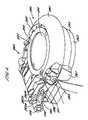
- FIG. 4is a perspective view of the brew head of the machine of FIG. 1 a with some parts omitted for clarity;
- FIG. 5is another perspective view of the brew head of the machine of FIG. 1 a with some parts omitted for clarity;
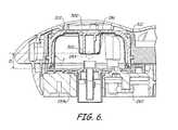
- FIG. 6is a cross-sectional view of the brew head in a closed position accommodating a second embodiment of beverage cartridge according to the present invention
- FIG. 7is a cross-sectional view of the brew head in an open position illustrated containing the second embodiment of cartridge of the present invention.
- FIG. 8is a schematic layout of the machine of FIG. 1 a;
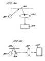
- FIGS. 9 a and 9 bare schematic layouts of first and second code recognition means for the machine of FIG. 1 a ;
- FIG. 10is a plan view of a beverage cartridge of the present invention.
- FIG. 11is cross-sectional drawing of an outer member of a first embodiment of cartridge of the present invention which may be used in the beverage preparation machine of the present invention
- FIG. 12is a cross-sectional drawing of a detail of the outer member of FIG. 11 showing an inwardly directed cylindrical extension
- FIG. 13is a cross-sectional drawing of a detail of the outer member of FIG. 11 showing a slot
- FIG. 14is a perspective view from above of the outer member of FIG. 11 ;
- FIG. 15is a perspective view from above of the outer member of FIG. 11 in an inverted orientation
- FIG. 16is a plan view from above of the outer member of FIG. 11 ;
- FIG. 17is a cross-sectional drawing of an inner member of the cartridge
- FIG. 18is a perspective view from above of the inner member of FIG. 17 ;
- FIG. 19is a perspective view from above of the inner member of FIG. 17 in an inverted orientation
- FIG. 20is a plan view from above of the inner member of FIG. 17 ;
- FIG. 21is a cross-sectional drawing of the first embodiment of cartridge in an assembled condition.
- FIG. 22is a cross-sectional drawing of a second embodiment of cartridge according to the present invention.
- FIGS. 1 a to 9 bA beverage preparation machine 201 of the beverage preparation system of the present invention is shown in FIGS. 1 a to 9 b .
- the beverage preparation machine 201generally comprises a housing 210 containing a water tank 220 , a water heater 225 , a water pump 230 , an air compressor 235 , a control processor, a user interface 240 and a brew head 250 .
- the brew head 250in turn generally comprises a holder 251 , recognition means 252 and inlet and outlet piercers 253 , 254 .
- the beverage preparation machine 201is designed to be capable of dispensing beverage ingredients from inserts in the form of cartridges 1 such as that illustrated in FIGS. 10 to 22 .
- FIGS. 10 to 21illustrate a first embodiment of the cartridge 1 .
- the cartridge 1generally comprises an outer member 2 , an inner member 3 and a laminate 5 .
- the outer member 2 , inner member 3 and laminate 5are assembled to form the cartridge 1 which has an interior 120 for containing one or more beverage ingredients, an inlet 121 , an outlet 122 and a beverage flow path linking the inlet 121 to the outlet 122 and which passes through the interior 120 .
- the inlet 121 and outlet 122are initially sealed by the laminate 5 and are opened in use by piercing or cutting of the laminate 5 .
- the beverage flow pathis defined by spatial inter-relationships between the outer member 2 , inner member 3 and laminate 5 as discussed below.
- Other componentsmay optionally be included in the cartridge 1 , such as a filter 4 , as will be described further below.
- the cartridge 1is particularly designed for use in dispensing filtered products such as roast and ground coffee or leaf tea.
- the cartridge 1may be used with other products such as chocolate, coffee, tea, sweeteners, cordials, flavourings, alcoholic beverages, flavoured milk, fruit juices, squashes, sauces and desserts.
- the overall shape of the cartridge 1is generally circular or disc-shaped with the diameter of the cartridge 1 being significantly greater than its height.
- a major axis Xpasses through the centre of the outer member as shown in FIG. 11 .
- the overall diameter of the outer member 2is 68.5 mm ⁇ 6 mm and the overall height is 16 mm ⁇ 3 mm.
- the volume of the cartridge 1 when assembledis 30.2 ml ⁇ 20%.
- the outer member 2generally composes a bowl-shaped shell 10 having a curved annular wall 13 , a closed top 11 and an open bottom 12 .
- the diameter of the outer member 2is smaller at the top 11 compared to the diameter at the bottom 12 , resulting from a flaring of the annular wall 13 as one traverses from the closed top 11 to the open bottom 12 .
- the annular wall 13 and closed bottom 11together define a receptacle having an interior 34 .
- a hollow inwardly directed cylindrical extension 18is provided in the closed top 11 centred on the major axis X.
- the interior surface of the cylindrical extension 18comprises a stepped profile having first, second and third portions 19 , 20 and 21 .
- the first portion 19is right circular cylindrical.
- the second portion 20is frusto-conical in shape and is inwardly tapered.
- the third portion 21is another right circular cylinder and is closed off by a lower face 31 .
- the diameter of the first, second and third portion 19 , 20 and 21incrementally decreases such that the diameter of the cylindrical extension 18 decreases as one traverses from the top 11 to the closed lower fate 31 of the cylindrical extension 18 .
- a generally horizontal shoulder 32is formed on the cylindrical extension 18 at the junction between the second and third portions 20 and 21 . From the outside, the cylindrical extension 18 forms a recess in the outer surface of the cartridge. A clamping surface 18 a is provided by the bottom of the recess as shown in FIG. 12 . The use of the clamping surface 18 a will be described below.
- An outwardly extending shoulder 33is formed in the outer member 2 towards the bottom 12 .
- the outwardly extending shoulder 33forms a secondary wall 15 co-axial with the annular wall 13 so as to define an annular track forming a manifold 16 between the secondary wall 15 and the annular wall 13 .
- the manifold 16passes around the circumference of the outer member 2 .
- a series or slots 17are provided in the annular wall 13 level with the manifold 16 to provide gas and liquid communication between the manifold 16 and the interior 34 of the outer member 2 . As shown in FIG. 13 , the slots 17 comprise vertical slits in the annular wall 13 . Between 20 and 40 slots are provided.
- thirty-seven slots 17are provided generally equi-spaced around the circumference of the manifold 16 .
- the slots 17are preferably between 1.4 and 1.8 mm in length. Typically the length of each slot is 1.6 mm representing 10% of the overall height of the outer member 2 .
- the width of each slotis between 0.25 and 0.33 mm. Typically, the width of each slot is 0.3 mm. The width of the slots 17 is sufficiently narrow to prevent the beverage ingredients passing therethrough into the manifold 16 either during storage or in use.
- An inlet chamber 26is formed in the outer member 2 at the periphery of the outer member 2 .
- a cylindrical wall 27is provided, as most clearly shown in FIG. 15 , which defines the inlet chamber 26 within, and partitions the inlet chamber 26 from, the interior 34 of the outer member 2 .
- the cylindrical wall 27has a closed upper face 28 which is formed on a plane perpendicular to the major axis X and an open lower end 29 co-planar with the bottom 12 of the outer member 2 .
- the inlet chamber 26communicates with the manifold 16 via two slots 30 as shown in FIG. 11 . Alternatively, between one and four slots may be used to communicate between the manifold 16 and the inlet chamber 26 .
- a lower end of the outwardly extending shoulder 33is provided with an outwardly extending flange 35 which extends perpendicularly to the major axis X.
- the flange 35has a width of between 2 and 4 mm.
- a portion of the flange 35is enlarged to form a handle 24 by which the outer member 2 may be held.
- the handle 24is provided with an upturned rim 25 to improve grip.
- the outer member 2is formed as a single integral piece from high density polyethylene, polypropylene, polystyrene, polyester, or a laminate of two or more of these materials.
- a suitable polypropyleneis the range of polymers available from DSM UK Limited (Redditch, United Kingdom).
- the outer membermay be opaque, transparent or translucent.
- the manufacturing processmay be injection moulding.
- the inner member 3 as shown in FIGS. 17 to 20comprises an annular frame 41 and a downwardly extending cylindrical funnel 40 .
- a major axis Xpasses through the centre of the inner member 3 as shown in FIG. 17 .
- the annular frame 41comprises an outer rim 51 and an inner hub 52 joined by ten equi-spaced radial spokes 53 .
- the inner hub 52is integral with and extends from the cylindrical funnel 40 .
- Filtration apertures 55are formed in the annular frame 41 between the radial spokes 53 .
- a filter 4is disposed on the annular frame 41 so as to cover the filtration apertures 55 .
- the filteris preferably made from a material with a high wet strength, for example a non-woven fibre material of polyester. Other materials which may be used include a water-impermeable cellulosic material, such as a cellulosic material comprising woven paper fibres.
- the woven paper fibresmay be admixed with fibres of polypropylene, polyvinyl chloride and/or polyethylene. The incorporation of these plastic materials into the cellulosic material renders the cellulosic material heat-sealable.
- the filter 4may also be treated or coated with a material which is activated by heat and/or pressure so that it can be sealed to the annular frame 41 in this way.
- the inner hub 52is located at a lower position than the outer rim 51 , resulting in the annular frame 41 having a sloping lower profile.
- each spoke 53is provided with an upstanding web 54 which divides a void space above the annular frame 41 into a plurality of passages 57 .
- Each passage 57is bounded on either side by a web 54 and on a lower face by the filter 4 .
- the passages 57extend from the outer rim 51 downwardly towards, and open into, the cylindrical funnel 40 at openings 56 defined by the inner extremities of the webs 54 .
- the cylindrical funnel 40comprises an outer tube 42 surrounding an inner discharge spout 43 .
- the outer tube 42forms the exterior of the cylindrical funnel 40 .
- the discharge spout 43is joined to the outer tube 42 at an upper end of the discharge spout 43 by means of an annular flange 47 .
- the discharge spout 43comprises an inlet 45 as an upper end which communicates with the openings 56 of the passages 57 and an outlet 44 at a lower end through which the prepared beverage is discharged into a cup or other receptacle.
- the discharge spout 43comprises a frusto-conical portion 48 at an upper end and a cylindrical portion 58 at a lower end.
- the cylindrical portion 58may have a slight taper such that it narrows towards the outlet 44 .
- the frusto-conical portion 48helps to channel beverage from the passages 57 down towards the outlet 44 without inducing turbulence to the beverages.
- An upper surface of the frusto-conical portion 48is provided with four support webs 49 equi-spaced around the circumference of the cylindrical funnel 40 .
- the support webs 49define channels 50 therebetween.
- the upper edges of the support webs 49are level with one another and perpendicular to the major axis X.
- the inner member 3may be formed as a single integral piece from polypropylene or a similar material as described above and by injection moulding in the same manner as the outer member 2 .
- the inner member 3 and/or the outer member 2may be made from a biodegradable polymer.
- suitable materialsinclude degradable polyethylene (for example, SPITEK supplied by Symphony Environmental, Borehamwood, United Kingdom), biodegradable polyester amide (for example, BAK 1095 supplied by Symphony Environmental), poly lactic acids (PLA supplied by Cargil, Minnesota, USA), starch-based polymers, cellulose derivatives and polypeptides.
- the laminate 5is formed from two layers, a first layer of aluminium and a second layer of cast polypropylene.
- the aluminium layeris between 0.02 and 0.07 mm in thickness.
- the cast polypropylene layeris between 0.025 and 0.065 mm in thickness.
- the aluminium layeris 0.06 mm and the polypropylene layer is 0.025 mm thick.
- This laminateis particularly advantageous as it has a high resistance to curling during assembly. As a result the laminate 5 may be pre-cut to the correct size and shape and subsequently transferred to the assembly station on the production line without undergoing distortion. Consequently, the laminate 5 is particularly well suited to welding.
- Other laminate materialsmay be used including PET/Aluminium/PP, PE/EVOH/PP, PET/metallised/PP and Aluminium/PP laminates. Roll laminate stock may be used instead of die cut stock.
- the cartridge 1may be closed by a rigid or semi-rigid lid instead of a flexible laminate.
- the outer member 2is orientated with the open bottom 12 directed upwards.
- the inner member 3is then inserted into the outer member 2 with the outer rim 51 being received as a loose fit in an axial extension 14 at top 11 of the cartridge 1 .
- the cylindrical extension 18 of the outer member 2is at the same time received in the upper portion of the cylindrical funnel 40 of the inner member 3 .
- the third portion 21 of the cylindrical extension 18is seated inside the cylindrical funnel 40 with the closed lower face 31 of the cylindrical extension 18 bearing against the support webs 49 of the inner member 3 .
- the filter 4is then placed over the inner member 3 such that the filter material contacts the annular rim 51 .
- An ultrasonic welding processis then used to join the filter 4 to the inner member 3 and at the same time, and in the same process step, the inner member 3 to the outer member 2 .
- the inner member 3 and filter 4are welded around the outer rim 51 .
- the inner member 3 and outer member 2are joined by means of weld lines around the outer rim 51 and also the upper edges of the webs 54 .
- the outer member 2 and inner member 3when joined together define a void space 130 in the interior 120 below the annular flange 41 and exterior the cylindrical funnel 40 which forms a filtration chamber.
- the filtration chamber 130 and passages 57 above the annular frame 41are separated by the filter paper 4 .
- the filtration chamber 130contains the one or more beverage ingredients 230 .
- the one or more beverage ingredientsare packed into the filtration chamber 130 .
- the ingredientis typically roast and ground coffee or leaf tea.
- the density of packing of the beverage ingredients in the filtration chamber 130can be varied as desired.
- the filtration chamber of the first embodiment of cartridgecontains between 5.0 and 10.2 grams of roast and ground coffee in a filtration bed of thickness of typically 5 to 14 mm.
- the interior 120may contain one or more bodies, such as spheres, which are freely movable within the interior 120 to aid mixing by inducing turbulence and breaking down deposits of beverage ingredients during discharge of the beverage.
- the laminate 5is then affixed to the outer member 2 by forming a weld 126 around the periphery of the laminate 5 to join the laminate 5 to the lower surface of the outwardly extending flange 35 .
- the weld 126is extended to seal the laminate 5 against the lower edge of the cylindrical wail 27 of the inlet chamber 26 .
- a weld 125is formed between the laminate 5 and the lower edge of the outer tube 42 of the cylindrical funnel 40 .
- the laminate 5forms the lower wall of the filtration chamber 130 and also seals the inlet chamber 26 and cylindrical funnel 40 .
- a small gap 123exists prior to dispensation between the laminate 5 and the lower edge of the discharge spout 43 .
- a variety of welding methodsmay be used, such as heat and ultrasonic welding, depending on the material characteristics of the laminate 5 .
- the inner member 3spans between the outer member 2 and the laminate 5 .
- the inner member 3is formed from a material of relative rigidity, such as polypropylene.
- the inner member 3forms a load-bearing member that acts to keep the laminate 5 and outer member 2 spaced apart when the cartridge 1 is compressed. It is preferred that the cartridge 1 is subjected to a compressive load of between 130 and 280N in use. The compressive force acts to prevent the cartridge failing under internal pressurisation and also serves to squeeze the inner member and outer member 2 together. This ensures that the internal dimensions of passageways and apertures in the cartridge 1 are fixed and unable to change during pressurisation of the cartridge 1 .
- the clamping surface 18 a at the bottom of the recess in the upper surface of the outer member 2 and the bottom surface of the laminate 5are separated by a distance d which is fixed by the relative dimensions of the inner member 3 and outer member 2 .
- the cartridge 1To use the cartridge 1 it is first inserted into the beverage preparation machine (as will be described below) and the inlet 121 and outlet 122 are opened by piercing members of the beverage preparation machine which perforate and fold back the laminate 5 .
- An aqueous mediumtypically water
- An aqueous mediumtypically water
- the wateris forced radially inwardly through the filtration chamber 130 and mixes with the beverage ingredients 200 contained therein.
- the wateris at the same time forced upwardly through the beverage ingredients.
- the beverage formed by passage of the water through the beverage ingredientspasses through the filter 4 and filtration apertures 55 into the passages 57 lying above the annular frame 41 .
- the sealing of the filter 4 onto the spokes 53 and the welding of the rim 51 with the outer member 2ensures that there are no short-circuits and all the beverage has to pass through the filter 4 .
- the beveragethen flows downwardly along the radial passages 57 formed between the webs 54 and through the openings 56 and into the cylindrical funnel 40 .
- the beveragepasses along the channels 50 between the support webs 47 and down the discharge spout 43 to the outlet 44 where the beverage is discharged into a receptacle such as a cup.
- the beverage preparation machinecomprises an air purge facility, wherein compressed air is forced through the cartridge 1 at the end of the dispense cycle to flush out the remaining beverage into the receptacle.
- the cartridge 1is provided on the laminate with a barcode 320 as shown in FIG. 10 .
- the barcode 320is formed from a plurality of bars of contrasting colour. Preferably the bars are black on a white background to maximise the contrast.
- the barcode 320is not required to conform to a published standard but a standard format for barcodes, such as EAN-13, UPC-A, or Interleaf 2 of 5 may be used.
- FIG. 22shows a second embodiment of beverage cartridge 1 according to the present invention.
- Like components between the first and second embodimentshave been referenced with like numerals. Many of the components and functions of the second embodiment of cartridge 1 are the same as for the first embodiment. However, it can be seen from FIG. 22 that the cartridge has a greater overall height compared to the cartridge shown in FIG. 21 .
- the outer member 2is taller and thereby defines a larger void space 130 in which a larger quantity of beverage ingredients can be stored.
- the second embodiment of cartridgeis therefore suitable for dispensing larger volumes of beverage.
- the diameter of the outer member 2 and cartridge 1are the same as in the first embodiment. Typically the storage volume of the cartridge 1 when assembled is 50 to 58 ml ⁇ 20%.
- the upper surface of the outer member 2is provided with a recess having a clamping surface 18 a located at a bottom thereof.
- the separation, d, between surface 18 a and the underside of the laminate 5is the same as for the first embodiment.
- the elongated recessextends approximately 60% of the distance towards the laminate 5 . This advantageously allows for a simplified clamping arrangement to be used as described below.
- cartridge 1The first and second embodiments of cartridge 1 described above are given as examples of the type of cartridge that embody the present invention.
- Other cartridges of a similar typemay be provided, in particular with different inner members 3 which are suitable for dispensing other beverage types, for example foamed milk, espresso-style coffee and chocolate.
- the housing 210contains and holds in position the other components of the machine 201 .
- the housing 210preferably made in whole or in part from a robust plastics material such as ABS.
- the housing 210can be made in whole or in part from a metallic material such as stainless steel or aluminium.
- the housing 210preferably comprises a clam-shell design having a front half 211 and a rear half 212 which allow access during assembly for fitting of the machine 201 components and can afterwards be joined together to define an interior 213 of the housing 210 .
- the rear half 212provides a recess 214 for the attachment of the water tank 220 .
- the housing 210is formed with means, such as detents, abutments, bosses and threaded portions, for retaining the components of the machine 201 in position without the need for a separate chassis. This reduces the overall cost and weight of the machine 201 .
- a base 215 of the housing 210is preferably provided with feet for standing the machine thereon in a stable manner. Alternatively, the base 215 itself may have a shape forming a stable support.
- the front half 211 of the housing 210comprises a dispense station 270 where dispensation of the beverage takes place.
- the dispense station 270comprises a receptacle stand 271 having a hollow interior forming a drip tray 272 .
- An upper surface 273 of the receptacle standis provided with a grill 274 on which the receptacle is positioned.
- the drip tray 272is removable from the housing 210 to ease emptying of the collected water.
- a recess 275is formed in the front half of the housing 210 above the receptacle stand 271 to accommodate the dimensions of the receptacle.
- the brew head 250is located towards the top of the housing 210 above the receptacle stand as shown in FIGS. 1 a and 1 b .
- the height of the grill 274 relative to the brew head 250can be adjusted to accommodate different sizes of receptacle. It is preferred that the receptacle is as close to the brew head 250 as possible, whilst still allowing the receptacle to be inserted and withdrawn from the dispense station 270 , so as to minimise the height that the dispensed beverage has to descend before contacting the receptacle. This acts to minimise spraying and splashing of the beverage and minimise loss of entrained air bubbles where these are present.
- receptacles of between 70 mm and 110 mm in heightcan be inserted between the grill 274 and brew head 250 .
- the machine user interface 240is located on the front of the housing 210 and comprises a start/stop button 241 , and a plurality of status indicators 243 - 246 .
- the status indicators 243 - 246preferably include a light emitting diode (LED) 243 to indicate readiness of the machine 201 , a LED 244 to indicate if an error has occurred in the machine 201 operation, and one or more LEDs 245 - 255 to indicate whether the machine 201 is operating in manual or automatic modes.
- the LEDs 243 - 246may be controlled to illuminate at a constant intensity, to flash intermittently, or both depending on the status of the machine 201 .
- the LEDs 243 - 246may have a variety of colours including green, red and yellow.
- the start/stop button 241controls commencement of the dispense cycle and is a manually operated push-button, switch or similar.
- a volume adjustment controlmay be provided to allow a user of the machine 201 to manually adjust the volume of the delivered beverage without altering the other operating characteristics.
- the volume adjustment controlallows an adjustment in volume of plus or minus 20%.
- the volume adjustment controlmay be a rotary knob, a linear slider, a digital readout with increment and decrement buttons, or similar. More typically, volume is controlled by a user operating the start/stop button 241 .
- a manual power switch(not shown) may be provided on the machine 201 .
- power supplycan be controlled simply by insertion or removal or the power supply plug from the mains power supply.
- the water tank 220is located to the rear of the housing 210 and is connected to the rear half 212 of the housing 210 .
- the water tank 220comprises a generally cylindrical body 221 which may be right circular or a frustum as desired for aesthetic reasons.
- the tankcomprises an inlet for filling the tank with water which is closed off in use by a manually removable lid 222 .
- An outletis provided towards a lower end of the tank which communicates with the water pump 230 .
- the water tank 220may be made from a transparent or translucent material to allow a consumer to view the quantity of water remaining in the tank. Alternatively, the water tank 220 may be made from an opaque material but have provided a viewing window therein.
- the water tank 220may be provided with a low level sensor which prevents operation of the water pump 230 and optionally triggers a warning indicator, such as an LED, when the water level in the tank descends to a preselected level.
- the water tank 220preferably has an internal capacity of approximately 1.5 liters.
- the water pump 230is operatively connected between the water tank 220 and the water heater 225 as shown schematically in FIG. 8 and is controlled by the control processor.
- the pumpprovides a maximum flow rate of 900 ml/min of water at a maximum pressure of 2.5 bar. Preferably, in normal use, the pressure will be limited to 2 bar.
- the flow rate of water through the machine 201can be controlled by the control processor to be a percentage of the maximum flow rate of the pump by cycle chopping the electrical supply to the pump.
- the pumpcan be driven at any of 10%, 20%, 30%, 40%, 50%, 60%, 70%, 80%, 90% or 100% of the maximum rated flow rate.
- the accuracy of the volume of water pumpedis preferably + or ⁇ 5% leading to a + or ⁇ 5% accuracy in the final volume of the dispensed beverage.
- a suitable pumpis the Evolution® EP8 pump produced by Ulka S.r.l. (Pavia, Italy).
- a volumetric flow sensor(not shown) is preferably provided in the flow line either upstream or downstream of the water pump 230 .
- the volumetric flow sensoris a rotary sensor.
- the water heater 225is located in the interior of the housing 210 .
- the heater 225has a power rating of 1550 W and is able to heat water received from the water pump 230 from a starting temperature of approximately 20° C. to an operating temperature of around 85° C. in under 1 minute.
- the dwell time between the end of one dispense cycle and the heater 225 being able to commence a subsequent dispense cycleis less than 10 seconds.
- the heatermaintains the selected temperature to within + or ⁇ 2° C. during the dispense cycle.
- the water for the dispense cyclemay be delivered to the brew head 250 at 83° C. or 93° C.
- the heater 225is able to quickly adjust the delivery temperature to either 83° C. or 93° C.
- the heater 225comprises an over-temperature cut-off which shuts off the heater if the temperature exceeds 98° C.
- Water output from the heater 225is fed to the brew head 250 by means of a three-way valve. If the pressure of the water flow is acceptable the water is passed to the cartridge 1 . If the pressure is below or above predetermined limits then the water is diverted by means of the three-way valve into the drip tray recovery receptacle 270 .
- the air compressor 235is operatively connected to the brew head 250 by means of a one-way valve and controlled by the control processor.
- the air compressor 235provides a maximum flow rate of air of 500 ml/min at 1.0 bar. In use a working volume of 35 ml is pressurised to 2.0 bar.
- the air compressor 235can produce two flow rates: a fast (or maximum) flow rate and a slow flow rate.
- the control processor of the beverage preparation machine 201comprises a processing module and a memory.
- the control processoris operatively connected to, and controls operation of, the water heater 225 , tracer pump 230 , air compressor 235 and user interface 240 .
- the memory of the control processorincludes one or more variables for one or more operational parameters for the beverage preparation machine 201 .
- the operational parametersare the temperature of the water passed through the beverage cartridge 1 during the operating stage, the speed of charging the beverage cartridge 1 , the presence or otherwise of a soak step, the total dispensed volume of the beverage, the flow rate of the water during the discharge stage, and the flow rate and period of the purge stage.
- the variables for the operational Parametersare stored in the memory.
- the cartridge 1comprises a code provided on or in the cartridge 1 representing the operational parameters required for optimal dispensation of the beverage in that cartridge 1 .
- the codeis in binary format and comprises a plurality of data bits corresponding to the variables stored in the control processor memory.
- the brew head 250is shown in FIGS. 4 to 7 .
- the holder 251 of the brew head 250comprises a fixed lower part 255 , a rotatable upper part 256 and a pivotable cartridge mount 257 positioned inbetween the fixed lower part 255 and the rotatable upper part 256 .
- the upper part 256 , lower part 255 and cartridge mount 257are rotated about a common hinge axis 258 .
- FIGS. 4 to 7show the holder 251 with some components of the machine 201 omitted for clarity.
- the rotatable upper part 256 and pivotable cartridge mount 257are moved relative to the fixed lower part 255 by means of a clamping mechanism 280 .
- the clamping mechanism 280comprises a clamping lever having first and second members or parts 281 and 282 .
- the first part 281 of the clamping levercomprises a U-shaped arm which is pivotably mounted to the upper part 256 at two first pivot points 283 , one on each side of the holder 251 .
- the second part of the clamping levercomprises two over-centre arms 282 , one on each side of the holder 251 which are each pivotably mounted to the upper part 256 at a second pivot point 285 located on the hinge axis 258 coupling the upper part 256 to the fixed lower part 255 .
- Each over-centre arm 282is a reciprocal member comprising a cylinder 282 a , a stem 282 b and a resilient sleeve 282 c .
- the cylinder 282 ahas an internal bore and is rotatably mounted at one end at the hinge axis 258 .
- a first end of the stem 282 bis slidingly received in the bore of the cylinder 282 a .
- the opposite end of the stem 282 bis rotatably mounted to the U-shaped arm 281 at a third pivot point 286 .
- the third pivot points 286are unconnected to, and freely moveable relative to, the upper part 256 and lower part 255 .
- the resilient sleeve 282 cis mounted externally on the stem 282 b and extends, in use, between abutment surfaces on the cylinder 282 a and stem 282 b .
- the resilient sleeve 282 caccommodates shortening of the over-centre arm 282 but biases the over-centre arm 282 into an extended configuration.
- the resilient sleeves 292 care preferably formed from silicone. Whilst the illustrated embodiment uses two over-centre arms 282 , it will be apparent that the closure mechanism may be configured with only one over-centre arm 282 .
- the U-shaped arm 281extends around the front of the holder 251 and comprises two downwardly dependant hook members 287 , one on each side of the holder 251 , each comprising a cam, surface 288 facing the hinge axis 258 .
- the fixed lower part 255 of the holder 251is provided with to bosses 259 , or detents, located one on each side of the lower part 255 at or near a front edge 260 thereof aligned generally with the hook members 287 .
- the U-shaped arm 281may be formed from a one piece plastics moulding comprising an ergonomic hand grip and the hook members 281 integral to the arm.
- the cartridge mount 257is rotatably mounted between the upper and lower parts 255 , 256 of the holder 251 .
- the mount 257is provided with a substantially circular recess 290 which receives in use the beverage cartridge 1 .
- the recess 290includes an irregularity 291 for accommodating the handle portion 24 of the beverage cartridge 1 which also acts to prevent rotation of the beverage cartridge 1 in the holder 251 .
- the cartridge mount 257is sprung relative to the fixed lower part 255 such that in the open position, as shown in FIG. 7 , the cartridge mount 257 is biased out of contact with the fixed lower part 255 so that the cartridge mount 257 is moved out of contact with the outlet and inlet piercer members 254 , 253 .
- the cartridge mount 257is provided with an aperture 292 for receiving therethrough the inlet and outlet piercers 253 , 254 and a head 300 of the cartridge recognition means 252 when the cartridge mount 257 is moved into the closed position.
- the upper part 255comprises a generally circular body 310 housing a circular viewing window 312 through which a consumer can view the beverage cartridge 1 during a dispense cycle and also visually confirm whether a cartridge 1 is loaded in the machine 201 .
- the viewing window 312is cup-shaped having a downwardly directed rim 311 .
- the viewing window 312is provided with a clamping member in the form of an inwardly directed tubular extension 500 as shown in FIG. 7 .
- the extension 500is directed towards the lower part 256 and lies within the volume of the brew head when in the closed position as shown in FIG. 6 .
- the viewing window 312is able to move axially relative to the body 310 of the upper part 255 .
- One arrangement of accomplishing the relative movementis to provide a wave spring (not shown), or similar resilient means such as a rubberised ring, positioned between the viewing window 312 and the circular body 310 .
- a series of helical compression springsare provided extending between the viewing window 312 and the body 310 . In both cases the resilient means allows the viewing window 312 to move axially relative to the circular body 310 by a small degree.
- FIG. 6In which the arrangement is illustrated containing a cartridge according to the second embodiment previously described).
- the pressure exerted by the tubular extension 500 on the outer member 2ensures a fluid tight seal between the cartridge 1 and the holder 251 .
- the height of the viewing window 312 and hence also the brew headis such that cartridges of various heights can be inserted.
- FIG. 6the arrangement is shown with the relative tall cartridge of the second embodiment described above. The same brew head can also accommodate the shorter cartridge of the first embodiment. In this case there will be a gap between the upper surface 11 or the cartridge 1 and the window 312 . However the cartridge 1 is fully sealed at inlet and outlet by the pressure applied by the tubular extension 500 .
- the lower part 255comprises the inlet and outlet piercers 253 , 254 and the head 300 of the cartridge recognition means 252 .
- the inlet piercer 253comprises a hollow needle-like tube 260 having a sharpened end 261 for perforating the laminate 5 of the beverage cartridge 1 in use.
- the inlet piercer 253is in fluid communication with a water conduit 262 as shown in FIG. 7 which passes through the lower part 255 and is connected to an outlet conduit 263 of the water heater 225 .
- the outlet piercer 254is similar in type to the outlet piercer described in the applicants's European patents EP 0 389 141 and EP 0 334 572 and comprises an open ended cylinder 264 of circular or D-shaped cross-section having dimensions larger than the discharge spout 43 .
- An arcuate portion 265 of the upper end of the outlet piercer 254is serrated to pierce and eventually cut the laminate of the beverage cartridge 1 .
- the remainder of the upper endis cut back longitudinally of the cylinder at least to the base of the teeth 266 of the serrated portion to fold or pull the cut laminate 5 away from the outlet aperture before the beverage is dispensed therethrough.
- the outlet piercer 254pierces the laminate 5 externally of the discharge spout 43 and when the cartridge mount 257 is in the closed position, rests in the annulus between the discharge spout 43 and the outer wait 42 of the discharge funnel 40 .
- the outlet piercer 254folds back the cut laminate 105 into the annulus. Thereby both the outlet piercer 254 and the cat laminate 105 are held out of the way of the discharged beverage.
- the outlet piercer 254is surrounded by a ledge 254 a which is raised relative to its surroundings by 0.5 mm.
- the outlet piercer 254is removable from the lower part 255 to enable it to be thoroughly cleaned, for example, in a dishwasher.
- the removable outlet piercer 254is received in a recess 267 in the lower part 255 where it is seated.
- the inlet piercer 253 and/or the outlet piercer 254may be made of a metal, such as stainless steel, or from a plastics material.
- the use of plastic cutting elementsis enabled by use of a laminate 5 which is able to be punctured and cut by a non-metallic material. Consequently, the piercers 253 , 254 can be made less sharp which lowers the risk of injury to the consumer.
- plastic piercing elementsare not prone to rust.
- the inlet piercer 253 and the outlet piercer 24are formed as a single, integral unit which is removable from the lower part 255 .
- the upper part 256 of the holder 251is movable from an open position in which it is orientated vertically or towards the vertical as shown in FIG. 1 b , to a closed position in which it is orientated substantially horizontally and in interengagement with the fixed lower part 255 and cartridge mount 257 .
- the upper part 256is moved from the open to the closed positions by operation of the clamping lever.
- To close the upper part 256a user takes hold of the clamping lever by the U-shaped arm 281 and pulls downwards. Consequently, the upper part 256 rotates which first brings the tubular extension 500 of the viewing window 312 into contact with the clamping surface 18 a of the beverage cartridge 1 .
- This movementallows for a take up of tolerances in the beverage cartridge 1 and beverage preparation machine and ensures that the amount of compressive force applied to the cartridge is kept within an acceptable range.
- the clamping force of the mechanismas moderated by the action of the wave spring or helical springs ensures a clamping pressure on the cartridge. It has been found that a pressure of between 50N and 280N is required. It will be noted that a lower pressure level is possible with this arrangement without a deleterious effect on the sealing of the cartridge 1 .
- the laminate 5 of the cartridge 1is tensioned as it is brought into contact with the ledge 254 a surrounding the outlet piercer 254 which causes the laminate 5 to flex out of plane as the distal end of the outer tube 42 of the cylindrical funnel is moved upwardly by 0.5 mm relative to the flange 35 .
- This movementalso ensures that the great majority of the compressive force applied to the cartridge acts through the central region of the cartridge 1 through the load-bearing inner member 3 .
- These clamping forceshelp prevent failure of the cartridge 1 during pressurisation and also ensure that the inner member 3 and outer member 2 are fully seated relative to one another and thus that all internal passageways and apertures remain at their intended dimensions even during internal pressurisation.
- the separation of the distal end 501 of the tubular extension 500 and the lower part 256is shown by reference D in FIG. 6 .
- This distanceis fixed by the dimensions of the viewing window 312 , body 310 and lower part 256 .
- the distance Dis chosen to be the same or marginally smaller than the distance d between the clamping surface 18 a and laminate under surface of the cartridges 1 .
- both the first and second embodiments or cartridgecan be clamped with the same degree of compression since distance d is the same for both cartridge types.
- An imaginary datum linecan be drawn between the first and second pivot points 283 , 285 of the holder 251 .
- the third pivot points 286are located on the side of the datum ling nearest the fixed lower part 255 .
- the third pivot points 286 of the clamping leverpass through the datum line joining the first and second pivot points 283 , 285 to the opposite side of the line, furthest from the fixed lower part 255 . Consequently, the U-shaped arm 281 ‘snaps through’ from a first stable position to a second stable position. The snap through action is accommodated by shortening of the over-centre arms 282 and consequential compression of the resilient sleeves 282 c .
- the clamping leverthus has a bi-stable operation in that the lever is stable in the open or closed positions but unstable at the point when the third pivot points 286 lie on the imaginary datum line joining the first and second pivot points 283 , 285 .
- the snap-through action of the clamping leverprovides a positive closure mechanism which leads to a definite closure action wherein in the final stages of the clamping lever's rotation, the snap-through action of the U-shaped arm 281 and second arms 284 forces the hook members 287 firmly into engagement with the bosses 259 .
- the resilient sleeves 282 cprovide a resistance to re-opening of the upper part 256 since a minimum force is required to compress the sleeves 282 c sufficiently to movie the third pivot points 286 back into line with the datum line joining the first and second pivot points 283 , 285 .
- the interengagement of the hook members 287 and the bosses 259prevents separation of the upper and lower parts other than by rotation of the clamping lever. This is useful in preventing opening of the brew head 250 during operation when the brew head 250 is subject to internal pressurisation.
- the recognition means 252comprises an optical barcode reader which reads the printed barcode 320 provided on the laminate 5 of the beverage cartridge 1 as shown in FIG. 10 and discussed above.
- the optical barcode readercomprises one or more LEDs 321 to illuminate the barcode 320 , a focusing lens 322 to acquire an image of the barcode, a charge coupled device (CCD) 323 for producing an electrical signal representative of the acquired image and support circuitry for the LEDs and CCD.
- CCDcharge coupled device
- a mirror or mirrors 324may be used to reflect the light from the LEDs 321 to a focussing lens which is not located in the lower part 255 .
- Schematic arrangementsare shown in FIGS. 9 a and 9 b .
- the lower part 255comprises an aperture 326 which is the same size as the barcode 320 on the beverage cartridge 1 .
- the aperture 320is closed by a window, preferably glass, which can transmit the signals produced by the barcode reader.
- the electrical signals producedare decoded by signal processing software and the results forwarded to the control processor.
- the softwarecan recognise whether the read of the barcode contained errors, although the occurrence of these is minimised as described above by specific location of the barcode 320 relative to the inlet.
- the barcode 320may be rescanned a number of times before an error message is presented to the consumer. If the machine 201 is unable to read the barcode the consumer is able to use the beverage cartridge 1 to dispense a beverage using a manual mode of operation. Alternatively, an RFID reader is provided to read an RFID located on the cartridge 1 .
- the brew head 250may also include a cartridge sensor for detecting whether a cartridge is present in the holder 251 .
- the brew head 250may also include a lock sensor which detects whether the holder 251 is properly closed.
- the lock sensorcomprises a micro-switch which is triggered when the holder 251 is closed and locked.
- the cartridge sensor and lock sensorare connected in series such that the output or both sensors must be satisfactory, i.e. cartridge present and mechanism locked, before the dispense cycle can be commenced.
- Operation of the machine 201comprises insertion of a beverage cartridge 1 into the brew head 250 , carrying out a dispense cycle in which the beverage is dispensed and removal of the cartridge 1 from the machine.
- the operational behaviour of the machine 201is determined by software embedded in the control processor.
- the holder 251is opened as described above to expose the cartridge mount 257 .
- the cartridge 1is then placed on the cartridge mount 257 received within the recess 290 such that the handle 24 of the cartridge is located in the irregularity 291 .
- the optical or magnetic barcode 320 or RFID of the cartridge 1is orientated directly above the aperture 326 in the cartridge mount 257 .
- the holder 251is then closed by operation of the clamping lever as described above.
- the inlet and outlet piercers 253 , 254pierce the laminate 5 of the cartridge 1 to form the cartridge inlet 121 and outlet 122 .
- the laminate 5 cut by the outlet piercer 254is folded up into the annulus surrounding the discharge spout 43 .
- the holder 251When closed the holder 251 grips the cartridge 1 around the rim 35 between the cartridge mount 257 and the upper part 256 and/or between the window 311 and the top 11 of the cartridge 1 to form a fluid tight seal of sufficient integrity to withstand the pressures developed during the dispense cycle.
- the consumeroperates the start/stop button 241 .
- the operating cyclecomprises the steps of cartridge recognition and the discharge cycle.
- Cartridge recognitionis performed by the optical recognition means 252 as described above assuming that the outputs from the cartridge sensor and lock sensor are satisfactory. Once the barcode 320 or RFID has been decoded the operational parameters of the machine 201 are adjusted by the control processor. The discharge cycle is then automatically commenced.
- the discharge cyclehas four main stages, not all of which are used for all beverage types:
- the cartridge 1In the pre-wet stage the cartridge 1 is charged with water from the water storage tank 220 by means of the water pump 230 .
- the charging with watercauses the beverage ingredients 200 in the filtration chamber 130 to be wetted.
- the chargingmay take place at a “fast” flow rate of 600 ml/min or a “slow” flow rate of 325 ml/min.
- the slow charging rateis particularly useful for cartridges containing viscous liquid beverage ingredients where the ingredients require some dilution before they are able to be pumped at a higher volume flow rate.
- the volume of water injected into the cartridge 1is selected to ensure that water or beverage does not drip out of the cartridge outlet 122 during this stage.
- the pause stageallows the beverage ingredients 200 to soak in the water injected during the pre-wet stage for a predetermined period of time.
- Both the pre-wetting and soaking stagesare known to increase the yield of the extractibles from the beverage ingredients 200 and to improve the end flavour of the beverage. Pre-wetting and soaking are particularly used where the beverage ingredients are roast and ground coffee.
- wateris passed through the cartridge 1 in order to produce the beverage from the beverage ingredients 200 .
- the temperature of the wateris determined by the control processor which sends instructions to the water heater 225 to heat the water passing from the water tank 220 to the brew head 250 .
- Waterenters the lower part 255 of the holder 251 through the conduit 262 via the inlet valve and the inlet piercer 253 into the inlet chamber 126 of the beverage cartridge 1 . Brewing and/or mixing and subsequent dispensing of the beverage from the beverage cartridge 1 is as described above with reference to the versions of the beverage cartridge 1 .
- the air purgecomprises the blowing of pressurised air through the beverage preparation machine and the beverage cartridge 1 to ensure that all beverage is dispensed and that the flow path is cleared ready for dispensing another beverage.
- the air purgedoes not commence immediately on cessation of the brew/mixing stage to allow for the majority of the fluid to clear the flow path. This prevents an unacceptable spike in internal pressure on commencement of the air purge.
- the consumerremoves the cartridge 1 by opening the holder 251 and manually removing and disposing of the cartridge.
- the machine 201may be provided with an automatic ejection mechanism for removing the cartridge automatically on opening the holder 251 .
Landscapes
- Engineering & Computer Science (AREA)
- Food Science & Technology (AREA)
- Mechanical Engineering (AREA)
- Apparatus For Making Beverages (AREA)
Abstract
Description
- a) the inner member3 is inserted into the
outer member 2; - b) the
filter 4 is cut to shape and placed onto the inner member3 so to be received over thecylindrical funnel 40 and come to rest against the annular frame41; - c) the inner member3,
outer member 2 andfilter 4 are joined by ultrasonic welding; - d) the
cartridge 1 is filled with one or more beverage ingredients; - e) the
laminate 5 is affixed to theouter member 2.
- a) the inner member3 is inserted into the
- (i) Pre-wet
- (ii) Pause
- (iii) Brew/Mixing
- (iv) Purge
Claims (20)
Applications Claiming Priority (3)
| Application Number | Priority Date | Filing Date | Title |
|---|---|---|---|
| GB0416705.2 | 2004-07-27 | ||
| GB0416705AGB2416480B (en) | 2004-07-27 | 2004-07-27 | A system for the preparation of beverages |
| PCT/US2005/026459WO2006014936A2 (en) | 2004-07-27 | 2005-07-26 | A cartridge, a machine, a system and a method for the preparation of beverages |
Related Parent Applications (1)
| Application Number | Title | Priority Date | Filing Date |
|---|---|---|---|
| PCT/US2005/026459A-371-Of-InternationalWO2006014936A2 (en) | 2004-07-27 | 2005-07-26 | A cartridge, a machine, a system and a method for the preparation of beverages |
Related Child Applications (1)
| Application Number | Title | Priority Date | Filing Date |
|---|---|---|---|
| US13/345,509DivisionUS9561900B2 (en) | 2004-07-27 | 2012-01-06 | Cartridge, a machine, a system and a method for the preparation of beverages |
Publications (2)
| Publication Number | Publication Date |
|---|---|
| US20080187638A1 US20080187638A1 (en) | 2008-08-07 |
| US8109200B2true US8109200B2 (en) | 2012-02-07 |
Family
ID=32947493
Family Applications (2)
| Application Number | Title | Priority Date | Filing Date |
|---|---|---|---|
| US11/572,617Active2027-04-21US8109200B2 (en) | 2004-07-27 | 2005-07-26 | Cartridge, a machine, a system and a method for the preparation of beverages |
| US13/345,509Active2027-08-20US9561900B2 (en) | 2004-07-27 | 2012-01-06 | Cartridge, a machine, a system and a method for the preparation of beverages |
Family Applications After (1)
| Application Number | Title | Priority Date | Filing Date |
|---|---|---|---|
| US13/345,509Active2027-08-20US9561900B2 (en) | 2004-07-27 | 2012-01-06 | Cartridge, a machine, a system and a method for the preparation of beverages |
Country Status (15)
| Country | Link |
|---|---|
| US (2) | US8109200B2 (en) |
| EP (1) | EP1796516B1 (en) |
| JP (1) | JP5068650B2 (en) |
| CN (3) | CN103040364B (en) |
| AR (1) | AR055235A1 (en) |
| AT (1) | ATE407601T1 (en) |
| CA (2) | CA2789731C (en) |
| DE (1) | DE602005009729D1 (en) |
| ES (1) | ES2313407T3 (en) |
| GB (1) | GB2416480B (en) |
| PE (1) | PE20060246A1 (en) |
| PL (1) | PL1796516T3 (en) |
| SI (1) | SI1796516T1 (en) |
| TW (3) | TWI440443B (en) |
| WO (1) | WO2006014936A2 (en) |
Cited By (40)
| Publication number | Priority date | Publication date | Assignee | Title |
|---|---|---|---|---|
| US20100189859A1 (en)* | 2006-07-26 | 2010-07-29 | Compagnie Mediterraneene Des Cafes S.A. | Device and process for brewing a drink |
| US20120207893A1 (en)* | 2009-10-19 | 2012-08-16 | Kruger Gmbh & Co. Kg | Brewing Device and Method for Extracting a Portion Capsule |
| USD674233S1 (en)* | 2011-11-10 | 2013-01-15 | Danny Lavy | Coffee maker |
| USD674232S1 (en)* | 2011-09-07 | 2013-01-15 | Danny Lavy | Coffee maker |
| US20130052305A1 (en)* | 2004-04-28 | 2013-02-28 | Hendrik Cornelis Koeling | Pad and assembly of a holder and such a pad |
| USD681386S1 (en)* | 2012-01-09 | 2013-05-07 | Luigi Lavazza S.P.A. | Machine for preparing beverages |
| USD681387S1 (en)* | 2012-01-09 | 2013-05-07 | Luigi Lavazza S.P.A. | Machine for preparing beverages |
| USD694620S1 (en) | 2011-03-08 | 2013-12-03 | Kraft Foods R&D, Inc. | Beverage cartridge |
| USD695111S1 (en) | 2011-03-23 | 2013-12-10 | Kraft Foods R&D, Inc. | Beverage cartridge |
| US20140170278A1 (en)* | 2011-07-12 | 2014-06-19 | Nestec S.A. | Actuator for closing a beverage ingredient holder |
| USD721248S1 (en)* | 2013-09-06 | 2015-01-20 | Keurig Green Mountain, Inc. | Front panel for a beverage machine |
| US9101243B2 (en) | 2011-05-26 | 2015-08-11 | The Richards Corporation | Universal espresso maker |
| US20150257586A1 (en)* | 2014-03-11 | 2015-09-17 | Starbucks Corporation Dba Starbucks Coffee Company | Single-serve beverage production machine |
| USD743786S1 (en) | 2012-09-12 | 2015-11-24 | Kraft Foods R & D, Inc. | Beverage cartridge |
| US9439532B2 (en) | 2014-03-11 | 2016-09-13 | Starbucks Corporation | Beverage production machines with multi-chambered basket units |
| US9474406B2 (en) | 2014-01-17 | 2016-10-25 | Keurig Green Mountain, Inc. | Apparatus with beverage cartridge holder having movable outlet |
| US9504348B2 (en) | 2014-03-11 | 2016-11-29 | Starbucks Corporation | Cartridge ejection systems and methods for single-serve beverage production machines |
| US9561900B2 (en) | 2004-07-27 | 2017-02-07 | Koninklijke Douwe Egberts B.V. | Cartridge, a machine, a system and a method for the preparation of beverages |
| US9783361B2 (en) | 2013-03-14 | 2017-10-10 | Starbucks Corporation | Stretchable beverage cartridges and methods |
| US9844293B2 (en) | 2015-03-06 | 2017-12-19 | Spectrum Brands, Inc. | Apparatus for dispensing beverages |
| US9877495B2 (en) | 2015-01-09 | 2018-01-30 | Starbucks Corporation | Method of making a sweetened soluble beverage product |
| US9930988B2 (en)* | 2012-08-21 | 2018-04-03 | Breville Pty Limited | Portafilter for capsule |
| US9932168B2 (en) | 2011-03-08 | 2018-04-03 | Kraft Foods R & D, Inc. | Beverage delivery pod and methods of use and manufacture |
| US9968217B2 (en) | 2015-06-16 | 2018-05-15 | Starbucks Corporation | Beverage preparation systems with brew chamber securing mechanisms |
| US10136754B2 (en) | 2014-01-17 | 2018-11-27 | Keurig Green Mountain, Inc. | Beverage machine cartridge holder |
| US10343838B2 (en) | 2012-06-18 | 2019-07-09 | K-Fee System Gmbh | Portion capsule and use of same for producing a beverage |
| US10342377B2 (en) | 2015-06-16 | 2019-07-09 | Starbucks Corporation | Beverage preparation systems with adaptable brew chambers |
| US10442610B2 (en) | 2014-03-11 | 2019-10-15 | Starbucks Corporation | Pod-based restrictors and methods |
| US10450131B2 (en) | 2014-10-01 | 2019-10-22 | Kraft Foods Group Brands Llc | Coffee pod |
| US10472165B2 (en) | 2012-12-14 | 2019-11-12 | K-Fee System Gmbh | Portion capsule and method for producing a beverage by means of a portion capsule |
| US10602874B2 (en) | 2015-06-16 | 2020-03-31 | Starbucks Corporation Dba Starbucks Coffee Company | Beverage preparation systems with brew chamber access mechanisms |
| US10669093B2 (en) | 2015-02-27 | 2020-06-02 | K-Fee System Gmbh | Single serve capsule comprising a filter element connected thereto by sealing |
| US10737876B2 (en) | 2015-07-13 | 2020-08-11 | K-Fee System Gmbh | Filter element having a cut-out |
| EP3701841A1 (en)* | 2012-12-19 | 2020-09-02 | Société des Produits Nestlé S.A. | Self-locking multi-size cartridge extraction unit |
| US10858177B2 (en) | 2010-07-22 | 2020-12-08 | K-Fee System Gmbh | Portion capsule having an identifier |
| US11045035B2 (en) | 2015-09-18 | 2021-06-29 | K-Fee System Gmbh | Adapter for a single serve capsule |
| US11084650B2 (en) | 2015-06-10 | 2021-08-10 | K-Fee System Gmbh | Portion capsule with a three-ply nonwoven fabric |
| US11524268B2 (en) | 2016-11-09 | 2022-12-13 | Pepsico, Inc. | Carbonated beverage makers, methods, and systems |
| US11820638B2 (en) | 2021-05-05 | 2023-11-21 | Black & Decker Inc. | Automated drink maker |
| US12227323B2 (en) | 2018-07-27 | 2025-02-18 | Gcs German Capsule Solution Gmbh | Method for producing a portion capsule |
Families Citing this family (97)
| Publication number | Priority date | Publication date | Assignee | Title |
|---|---|---|---|---|
| US8327754B2 (en) | 2003-07-22 | 2012-12-11 | The Coca-Cola Company | Coffee and tea pod |
| US8505440B2 (en) | 2003-07-22 | 2013-08-13 | The Coca-Cola Company | System for varying coffee intensity |
| PT1826148E (en)* | 2006-02-27 | 2010-06-07 | Nestec Sa | Beverage-ingredient capsule with jet direction-diverting member |
| US7947316B2 (en) | 2006-08-04 | 2011-05-24 | The Coca-Cola Company | Pod for dispersible materials |
| US7964230B2 (en) | 2006-08-04 | 2011-06-21 | The Coca-Cola Company | Method of sealing a pod for dispersible materials |
| RU2403199C1 (en)* | 2006-09-19 | 2010-11-10 | Рпк Брамлаге Гмбх | Container beverages storage and preparation consisting of inner part and outer part |
| ATE471895T1 (en)* | 2006-09-19 | 2010-07-15 | Rpc Bramlage Gmbh | STORAGE AND PROCESS CONTAINER FOR A BEVERAGE MACHINE |
| FR2908970A1 (en) | 2006-11-28 | 2008-05-30 | Rolland Versini | Spherical disposable capsule for automatic beverage preparing and distributing machine, has conditioning envelope presenting spherical external shape to be pierced on any part of evelop's surface |
| US7863546B2 (en) | 2006-12-27 | 2011-01-04 | Kraft Foods Global Brands Llc | Automated preparation of infant formula and children's beverages |
| ES2661027T3 (en)* | 2007-01-15 | 2018-03-27 | Swiss Caffe Asia Ltd. | Capsule, means of penetration of the bottom of a capsule and device for preparing a beverage |
| FR2912124B1 (en)* | 2007-02-01 | 2012-10-05 | Cie Mediterraneenne Des Cafes | PACKAGING FOR PREPARING BEVERAGES WITH RFID LABEL |
| PL1967099T3 (en) | 2007-03-06 | 2010-06-30 | Nestec Sa | Device for preparing a food liquid from a capsule |
| TWI573802B (en)* | 2007-03-06 | 2017-03-11 | 安美基公司 | Mutant activin receptor polypeptide and use thereof |
| NL2000572C2 (en)* | 2007-04-03 | 2008-10-06 | Ferro Techniek Holding Bv | Method and device for preparing beverages by extraction. |
| CA2688310C (en) | 2007-06-05 | 2015-11-17 | Nestec S.A. | Method for preparing a beverage or liquid food and system using brewing centrifugal force |
| US8431175B2 (en) | 2007-06-05 | 2013-04-30 | Nestec S.A. | Method for preparing a beverage or food liquid and system using brewing centrifugal force |
| BRPI0812339B1 (en) | 2007-06-05 | 2020-08-11 | Société Des Produits Nestlé S.A | SYSTEM AND METHOD FOR THE PREPARATION OF A FOOD LIQUID AND DEVICE FOR THE PREPARATION OF LIQUID FOOD |
| WO2008148650A1 (en) | 2007-06-05 | 2008-12-11 | Nestec S.A. | Single-use capsule for preparing a food liquid by centrifugation |
| KR20100017635A (en) | 2007-06-05 | 2010-02-16 | 네스텍 소시에테아노님 | Capsule and method for preparing a food liquid by centrifugation |
| US11832755B2 (en)* | 2007-07-13 | 2023-12-05 | Adrian Rivera | Brewing material container for a beverage brewer |
| US10722066B2 (en)* | 2010-12-04 | 2020-07-28 | Adrian Rivera | Windowed single serving brewing material holder |
| US20090036639A1 (en)* | 2007-07-31 | 2009-02-05 | The Coca-Cola Company | Post-Processing of Polylactic Acid Article |
| AT506710B1 (en)* | 2008-05-05 | 2011-05-15 | Hagleitner Hans Georg | DONOR |
| US8043645B2 (en) | 2008-07-09 | 2011-10-25 | Starbucks Corporation | Method of making beverages with enhanced flavors and aromas |
| CA2728224A1 (en)* | 2008-07-14 | 2010-01-21 | Nestec S.A. | Water circulation system for a beverage preparation device |
| AU2009289682B2 (en) | 2008-09-02 | 2016-06-09 | Société des Produits Nestlé S.A. | Controlled beverage production device using centrifugal forces |
| WO2010026045A1 (en) | 2008-09-02 | 2010-03-11 | Nestec S.A. | Method for preparing a food liquid contained in a capsule by centrifugation and system adapted for such method |
| JP5497778B2 (en) | 2008-12-09 | 2014-05-21 | ネステク ソシエテ アノニム | Liquid food preparation system for preparing liquid food by centrifugation |
| BRPI0923895A2 (en)* | 2009-01-02 | 2015-07-28 | Ethical Coffee Company Sa | Capsule for the preparation of a drink and device |
| EP2223869A1 (en)* | 2009-02-27 | 2010-09-01 | Uwe Wons | Machine readable, fully biodegradable portion pad for the preparation of drinks |
| EP2236060A1 (en)* | 2009-03-23 | 2010-10-06 | Koninklijke Philips Electronics N.V. | A method for making an iced beverage and a package containing a liquid |
| GB2469874B (en) | 2009-05-01 | 2012-09-19 | Kraft Foods R & D Inc | Beverage preparation machines |
| WO2010137959A1 (en)* | 2009-06-17 | 2010-12-02 | Sara Lee/De N.V. | System and method for preparing a predetermined quantity of beverage |
| CA2767138A1 (en)* | 2009-07-03 | 2011-01-06 | Smart Wave Integrated Products, Inc. | System and method for communication between a fluid filtration apparatus and filter |
| EP2272407A1 (en)* | 2009-07-09 | 2011-01-12 | Koninklijke Philips Electronics N.V. | Kitchen appliance |
| DK2592021T3 (en) | 2009-08-19 | 2015-04-27 | Nestec Sa | The capsule for preparing a coffee extract having a structure that facilitates perforation for injecting water |
| US8658232B2 (en) | 2009-08-28 | 2014-02-25 | Nestec S.A. | Capsule system for the preparation of beverages by centrifugation |
| CN102595983B (en) | 2009-08-28 | 2015-04-15 | 雀巢产品技术援助有限公司 | Capsule system for preparing beverages by centrifugation |
| GB2475291B (en) | 2009-11-12 | 2012-03-28 | Kraft Foods R & D Inc | Beverage preparation machines |
| BR112012011161A8 (en) | 2009-11-12 | 2019-02-12 | Formulanow Llc | punching, cartridge and mixing equipment and method for combining mixing and liquid |
| GB2475290A (en)* | 2009-11-12 | 2011-05-18 | Kraft Foods R & D Inc | Nozzle for beverage preparation machines |
| CA2781963C (en) | 2009-12-08 | 2014-01-07 | International Paper Company | Thermoformed articles made from reactive extrusion products of biobased materials |
| BR112012017591A2 (en)* | 2010-01-15 | 2016-08-16 | Nestec Sa | ergonomic service unit for beverage preparation machines |
| JP2013517026A (en)* | 2010-01-15 | 2013-05-16 | ネステク ソシエテ アノニム | Cooperation between ergonomic raw material holder and service unit |
| EP2345352A1 (en)* | 2010-01-19 | 2011-07-20 | Nestec S.A. | Method for providing information to a user from a capsule for the preparation of a beverage using a code |
| US20110174168A1 (en)* | 2010-01-21 | 2011-07-21 | AMF Automation Technologies, LLC d/b/a AMF Bakery Systems | Dough Pump and Developer |
| DE102010044945A1 (en)* | 2010-05-28 | 2011-12-01 | Eugster/Frismag Ag | Brewing device for extracting a portion capsule, method for operating a brewing device, method for producing a brewing device and use of a brewing device |
| US10071851B2 (en) | 2010-07-12 | 2018-09-11 | Robert Bao Vu | Apparatus and products for producing beverages, and methods for making and using same |
| PT2409608E (en)* | 2010-07-19 | 2013-07-26 | Nestec Sa | Device for sensing a capsule in a beverage production apparatus |
| BR112013011242A2 (en)* | 2010-11-11 | 2016-11-01 | Nestec S A Ch | capsule, beverage production machine and system for preparing a nutritional product |
| GB2486487B (en)* | 2010-12-16 | 2015-09-02 | Kraft Foods R & D Inc | Instant coffee |
| WO2012116192A1 (en)* | 2011-02-23 | 2012-08-30 | Fka Distributing Co., D/B/A Homedics, Inc. | Baby food preparation apparatus |
| CA2855711C (en)* | 2011-11-15 | 2019-03-05 | Nestec S.A. | Optical readable code support and capsule for preparing a beverage having such code support providing an enhanced readable optical signal |
| GB2499005B (en)* | 2012-02-02 | 2014-06-25 | Kraft Foods R & D Inc | Improvements in or relating to beverage preparation machines |
| GB2499004A (en) | 2012-02-02 | 2013-08-07 | Kraft Foods R & D Inc | Clamping mechanism for a beverage preparation machine |
| GB2499201B (en) | 2012-02-07 | 2014-07-02 | Kraft Foods R & D Inc | A beverage preparation system, a coded insert and methods of use thereof |
| WO2013130576A1 (en)* | 2012-02-28 | 2013-09-06 | Purpod Holdings, Llc | A nutracuetical compounding system and method therefore |
| KR102075814B1 (en) | 2012-06-22 | 2020-02-10 | 터치 커피 & 베버리지스, 엘엘씨. | Beverage brewing system |
| GB2504947B (en) | 2012-08-13 | 2015-01-14 | Kraft Foods R & D Inc | Beverage preparation machines |
| MX2015002273A (en)* | 2012-08-22 | 2015-05-08 | Nestec Sa | Capsule assemblies with data storage and communication means. |
| RU2015116419A (en) | 2012-10-09 | 2016-11-27 | Нестек С.А. | EXTRACTION DEVICE WITH ADJUSTABLE RECEIVER FOR VARIOUS SIZES CAPSULES |
| CN103040357A (en)* | 2013-01-08 | 2013-04-17 | 周林斌 | Coffee maker and coffee making method |
| CN105473031B (en)* | 2013-05-10 | 2018-11-02 | 竹斯柔公司 | Juicing system and method |
| DE102013110121A1 (en)* | 2013-09-13 | 2015-03-19 | Krones Ag | Disposable emptying system for containers |
| JP6173602B2 (en)* | 2013-12-20 | 2017-08-02 | コーニンクレッカ フィリップス エヌ ヴェKoninklijke Philips N.V. | Consumables recognition system and beverage dispenser |
| US9327900B2 (en)* | 2014-09-09 | 2016-05-03 | Keurig Green Mountain, Inc. | Method and apparatus for cartridge-based carbonation of beverages |
| WO2016080835A1 (en) | 2014-11-20 | 2016-05-26 | Koninklijke Douwe Egberts B.V. | An apparatus for preparing a coffee beverage, a system comprising such an apparatus, use of a coffee container in such a system or in such an apparatus and a method for preparing a coffee beverage using such an apparatus or using such a system |
| MX389243B (en)* | 2015-05-07 | 2025-03-20 | Smart Wave Tech Corp | Signal and detection system for pairing products |
| US20170252995A1 (en)* | 2016-03-03 | 2017-09-07 | Juicero, Inc. | Juicer cartridge with outlet separator |
| US20170252998A1 (en)* | 2016-03-03 | 2017-09-07 | Juicero, Inc. | Juicer cartridge with flow disruptor |
| US20170252990A1 (en)* | 2016-03-03 | 2017-09-07 | Juicero, Inc. | Juicer cartridge geometry |
| US20170252999A1 (en)* | 2016-03-03 | 2017-09-07 | Juicero, Inc. | Juicer with juicer cartridge orientation feature |
| US20170252991A1 (en)* | 2016-03-03 | 2017-09-07 | Juicero, Inc. | Juicer with flexible seal |
| US20170252994A1 (en)* | 2016-03-03 | 2017-09-07 | Juicero, Inc. | Juicing system with juicer cartridge restraints |
| US20170252997A1 (en)* | 2016-03-03 | 2017-09-07 | Juicero, Inc. | Juicer cartridge with sanitary seal |
| US20170252993A1 (en)* | 2016-03-03 | 2017-09-07 | Juicero, Inc. | Juicer cartridge with coupling |
| US20170252996A1 (en)* | 2016-03-03 | 2017-09-07 | Juicero, Inc. | Juicer cartridge with secondary flow channel |
| US20170253000A1 (en)* | 2016-03-03 | 2017-09-07 | Juicero, Inc. | Juicer with locking mechanism |
| EP3457906B1 (en)* | 2016-05-20 | 2023-08-02 | Illinois Tool Works Inc. | Automatic door for dishwasher with multi-position sensing |
| NL2017283B1 (en) | 2016-08-03 | 2018-02-14 | Douwe Egberts Bv | System and apparatus for preparing a beverage |
| NL2017285B1 (en) | 2016-08-03 | 2018-02-14 | Douwe Egberts Bv | System, apparatus, method, capsule and kit of capsules for preparing a beverage |
| NL2017278B1 (en) | 2016-08-03 | 2018-02-14 | Douwe Egberts Bv | System, apparatus, method, capsule and kit of capsules for preparing a beverage |
| NL2017277B1 (en) | 2016-08-03 | 2018-02-14 | Douwe Egberts Bv | Apparatus and method for preparing a beverage and system comprising the apparatus and an exchangeable capsule |
| NL2019218B1 (en) | 2016-08-03 | 2018-07-06 | Douwe Egberts Bv | Capsule, system and use of the system for preparing double beverages like a double espresso, a double lungo and a double ristretto |
| NL2017280B1 (en) | 2016-08-03 | 2018-02-14 | Douwe Egberts Bv | System for preparing a beverage |
| NL2017282B1 (en) | 2016-08-03 | 2018-02-14 | Douwe Egberts Bv | System for preparing a beverage |
| NL2017284B1 (en) | 2016-08-03 | 2018-02-14 | Douwe Egberts Bv | System and method for preparing a beverage field and background |
| NL2017281B1 (en) | 2016-08-03 | 2018-02-14 | Douwe Egberts Bv | System for preparing a beverage |
| NL2017279B1 (en) | 2016-08-03 | 2018-02-14 | Douwe Egberts Bv | System for preparing a beverage |
| US11399652B2 (en)* | 2016-12-29 | 2022-08-02 | Koninklijke Philips N.V. | Method and device for providing a coffee beverage with reduced terpene content |
| PT3372122T (en)* | 2017-03-10 | 2020-07-02 | Delica Ag | Adapter for use in the preparation of a beverage |
| CN108968112B (en) | 2017-06-01 | 2021-05-18 | 志勇无限创意股份有限公司 | Bean roasting device |
| TWI646904B (en)* | 2017-06-01 | 2019-01-11 | 志勇無限創意有限公司 | Bean roasting apparatus |
| JP6480525B2 (en)* | 2017-08-07 | 2019-03-13 | 株式会社Tree Field | Beverage production equipment |
| CA3121432A1 (en)* | 2018-12-12 | 2020-06-18 | Societes Des Produits Nestle S.A. | Beverage preparation machine with capsule recognition |
| US11805934B1 (en)* | 2020-10-21 | 2023-11-07 | Adrian Rivera | Brewing material lid and container for a beverage brewer |
| DE102021131239A1 (en)* | 2021-11-29 | 2023-06-01 | Top Cap Holding Gmbh | Can end and method of making a can end |
Citations (16)
| Publication number | Priority date | Publication date | Assignee | Title |
|---|---|---|---|---|
| GB838829A (en) | 1956-06-22 | 1960-06-22 | Guy Raymond Donot | Apparatus for producing infusions, decoctions and the like beverages |
| US3445237A (en) | 1966-06-28 | 1969-05-20 | Lester Gidge | Preshaped cartridge for,and method of packaging,percolator ground coffee |
| EP0398524A2 (en) | 1989-05-15 | 1990-11-22 | Hag Gf Aktiengesellschaft | An improved coffee cassette |
| US5197374A (en) | 1990-07-27 | 1993-03-30 | Nestec S.A. | Apparatus for extracting cartridges containing coffee |
| WO1995007648A1 (en) | 1993-09-17 | 1995-03-23 | Mars G.B. Limited | Beverage brewing |
| US5656311A (en) | 1991-07-05 | 1997-08-12 | Nestec S.A. | Cartridges having interiorly positioned zones of reduced thickness |
| US5656316A (en) | 1991-05-08 | 1997-08-12 | Nestec S.A. | Obtaining fluid comestibles from substances contained in cartridges |
| EP1042978A1 (en) | 1999-04-08 | 2000-10-11 | LUIGI LAVAZZA S.p.A. | A disposable cartridge for use in a machine for the extraction and delivery of beverages |
| JP2001061663A (en) | 1999-08-24 | 2001-03-13 | Toyo Seikan Kaisha Ltd | Sealed container for beverage preparation |
| US20020078831A1 (en) | 2000-12-22 | 2002-06-27 | Cai Edward Zhihua | Cartridge and method for making fluid comestibles |
| WO2003059778A2 (en) | 2002-01-16 | 2003-07-24 | Societe Des Produits Nestle S.A. | Closed capsule with opening mean |
| US20030145736A1 (en)* | 2002-02-07 | 2003-08-07 | Green Charles Bradley | Coffee and tea dispenser |
| WO2004006740A2 (en) | 2002-07-12 | 2004-01-22 | Seb S.A. | Cartridge-operated coffee-machine |
| JP2004514488A (en) | 2000-11-28 | 2004-05-20 | ソシエテ デ プロデユイ ネツスル ソシエテ アノニム | Leaching device |
| EP1440644A1 (en) | 2003-01-24 | 2004-07-28 | Kraft Foods R & D, Inc. | Machine for the preparation of beverages |
| WO2005072574A1 (en) | 2004-01-30 | 2005-08-11 | BSH Bosch und Siemens Hausgeräte GmbH | Coffee machine having a drawer through which it is supplied with a coffee pad |
Family Cites Families (25)
| Publication number | Priority date | Publication date | Assignee | Title |
|---|---|---|---|---|
| IT1210982B (en) | 1981-02-03 | 1989-09-29 | Giuseppe Stefano Piana | DISPOSABLE CAPSULE, FOR THE PACKAGE OF WATER SOLUBLE PREPARATIONS IN DOSES, SUITABLE TO ALLOW THE PREPARATION OF HOT DRINKS IN GENERAL. |
| DK162369C (en)* | 1982-07-19 | 1992-03-23 | Mars G B Ltd | METHOD AND DISPENSES FOR THE PREPARATION OF AN INFUSIONAL BEVERAGE |
| FI83197C (en)* | 1984-10-23 | 1991-06-10 | Mars G B Ltd | DRYCKPAOSE. |
| ATE93373T1 (en) | 1990-07-27 | 1993-09-15 | Nestle Sa | METHOD FOR BREWING CLOSED PORTION PACKS AND APPARATUS FOR CARRYING OUT THESE METHOD. |
| EP0471094B1 (en) | 1990-07-27 | 1993-12-01 | Societe Des Produits Nestle S.A. | Insert to be fitted in a cartridge holder |
| US5897899A (en) | 1991-05-08 | 1999-04-27 | Nestec S.A. | Cartridges containing substances for beverage preparation |
| US5327815A (en) | 1991-07-05 | 1994-07-12 | Nestec S.A. | Device for use in beverage extraction machines |
| DE69114277T2 (en) | 1991-07-05 | 1996-06-27 | Nestle Sa | Device for extracting cartridges, usable for every espresso machine. |
| DK0521186T3 (en) | 1991-07-05 | 1995-04-18 | Nestle Sa | Soft packaging and process for its manufacture |
| ES2080196T3 (en) | 1991-07-05 | 1996-02-01 | Nestle Sa | DEVICE FOR THE EXTRACTION OF CARTRIDGES. |
| US5913445A (en)* | 1996-08-07 | 1999-06-22 | Nippon Sanso Corporation | Insulated synthetic resin container and insulated synthetic resin lid |
| US5775205A (en)* | 1996-12-16 | 1998-07-07 | Melton; Bruce W. | Infuser unit for beverages |
| PT1028068E (en)* | 1999-02-12 | 2003-06-30 | Nestle Sa | A RECOVERY CARTRIDGE FOR A BEVERAGE DISTRIBUTION DEVICE AND DEVICE ADAPTED TO THIS CARTRIDGE |
| JP2000355375A (en) | 1999-06-09 | 2000-12-26 | Toyo Seikan Kaisha Ltd | Sealing container for preparing drink |
| CN1512457A (en)* | 1999-08-14 | 2004-07-14 | 宝洁公司 | Method and system for providing customized beverages according to user needs using delayed dilution technology |
| ES2396691T3 (en)* | 1999-08-14 | 2013-02-25 | The Folger Coffee Company | Methods and systems that use delayed dilution, mixing and filtering to provide beverages prepared to taste upon request |
| US6832542B2 (en)* | 2001-03-23 | 2004-12-21 | Nestec S.A. | Method and device for preparing a hot beverage |
| DE60236385D1 (en)* | 2001-04-27 | 2010-06-24 | Mars Inc | Beverage manufacturing device and process |
| TW200306280A (en)* | 2001-11-30 | 2003-11-16 | Beverage Works Inc | Beverage dispensing apparatus |
| US20050188854A1 (en)* | 2002-02-07 | 2005-09-01 | The Coca-Cola Co. | Coffee and tea dispenser |
| US7592027B2 (en)* | 2003-01-24 | 2009-09-22 | Kraft Foods R & D, Inc. | Method for the preparation of beverages |
| US6948420B2 (en)* | 2003-07-22 | 2005-09-27 | The Coca-Cola Company | Coffee and tea pod |
| CA2436274C (en)* | 2003-07-28 | 2006-09-19 | Dean Robert Rosendahl | A router construction for clearing machined materials |
| MY138658A (en)* | 2004-02-20 | 2009-07-31 | Nestec Sa | System for dispensing short and long coffee beverages |
| GB2416480B (en) | 2004-07-27 | 2007-12-27 | Kraft Foods R & D Inc | A system for the preparation of beverages |
- 2004
- 2004-07-27GBGB0416705Apatent/GB2416480B/ennot_activeExpired - Lifetime
- 2005
- 2005-07-25TWTW094125151Apatent/TWI440443B/ennot_activeIP Right Cessation
- 2005-07-25TWTW101122767Apatent/TWI483700B/ennot_activeIP Right Cessation
- 2005-07-25TWTW103102244Apatent/TWI480014B/ennot_activeIP Right Cessation
- 2005-07-26JPJP2007523721Apatent/JP5068650B2/ennot_activeExpired - Fee Related
- 2005-07-26WOPCT/US2005/026459patent/WO2006014936A2/enactiveApplication Filing
- 2005-07-26USUS11/572,617patent/US8109200B2/enactiveActive
- 2005-07-26EPEP05781266Apatent/EP1796516B1/ennot_activeExpired - Lifetime
- 2005-07-26CACA2789731Apatent/CA2789731C/ennot_activeExpired - Lifetime
- 2005-07-26ESES05781266Tpatent/ES2313407T3/ennot_activeExpired - Lifetime
- 2005-07-26DEDE602005009729Tpatent/DE602005009729D1/ennot_activeExpired - Lifetime
- 2005-07-26CACA2574961Apatent/CA2574961C/ennot_activeExpired - Lifetime
- 2005-07-26PEPE2005000874Apatent/PE20060246A1/ennot_activeApplication Discontinuation
- 2005-07-26PLPL05781266Tpatent/PL1796516T3/enunknown
- 2005-07-26ATAT05781266Tpatent/ATE407601T1/ennot_activeIP Right Cessation
- 2005-07-26CNCN201310026662.1Apatent/CN103040364B/ennot_activeExpired - Lifetime
- 2005-07-26CNCN201610025760.7Apatent/CN105595841B/ennot_activeExpired - Lifetime
- 2005-07-26CNCNA2005800316747Apatent/CN101090657A/enactivePending
- 2005-07-26SISI200530502Tpatent/SI1796516T1/enunknown
- 2005-07-27ARARP050103116Apatent/AR055235A1/enunknown
- 2012
- 2012-01-06USUS13/345,509patent/US9561900B2/enactiveActive
Patent Citations (19)
| Publication number | Priority date | Publication date | Assignee | Title |
|---|---|---|---|---|
| GB838829A (en) | 1956-06-22 | 1960-06-22 | Guy Raymond Donot | Apparatus for producing infusions, decoctions and the like beverages |
| US3445237A (en) | 1966-06-28 | 1969-05-20 | Lester Gidge | Preshaped cartridge for,and method of packaging,percolator ground coffee |
| EP0398524A2 (en) | 1989-05-15 | 1990-11-22 | Hag Gf Aktiengesellschaft | An improved coffee cassette |
| US5197374A (en) | 1990-07-27 | 1993-03-30 | Nestec S.A. | Apparatus for extracting cartridges containing coffee |
| US5656316A (en) | 1991-05-08 | 1997-08-12 | Nestec S.A. | Obtaining fluid comestibles from substances contained in cartridges |
| US5656311A (en) | 1991-07-05 | 1997-08-12 | Nestec S.A. | Cartridges having interiorly positioned zones of reduced thickness |
| WO1995007648A1 (en) | 1993-09-17 | 1995-03-23 | Mars G.B. Limited | Beverage brewing |
| EP1042978A1 (en) | 1999-04-08 | 2000-10-11 | LUIGI LAVAZZA S.p.A. | A disposable cartridge for use in a machine for the extraction and delivery of beverages |
| JP2001061663A (en) | 1999-08-24 | 2001-03-13 | Toyo Seikan Kaisha Ltd | Sealed container for beverage preparation |
| JP2004514488A (en) | 2000-11-28 | 2004-05-20 | ソシエテ デ プロデユイ ネツスル ソシエテ アノニム | Leaching device |
| US20020078831A1 (en) | 2000-12-22 | 2002-06-27 | Cai Edward Zhihua | Cartridge and method for making fluid comestibles |
| WO2003059778A2 (en) | 2002-01-16 | 2003-07-24 | Societe Des Produits Nestle S.A. | Closed capsule with opening mean |
| US20040228955A1 (en)* | 2002-01-16 | 2004-11-18 | Jean-Luc Denisart | Closed capsule with opening means |
| US20030145736A1 (en)* | 2002-02-07 | 2003-08-07 | Green Charles Bradley | Coffee and tea dispenser |
| WO2004006740A2 (en) | 2002-07-12 | 2004-01-22 | Seb S.A. | Cartridge-operated coffee-machine |
| US20050223904A1 (en)* | 2002-07-12 | 2005-10-13 | Gilles Laigneau | Cartridge-operated coffee-machine |
| US7325479B2 (en)* | 2002-07-12 | 2008-02-05 | Seb S.A. | Cartridge-operated coffee-machine |
| EP1440644A1 (en) | 2003-01-24 | 2004-07-28 | Kraft Foods R & D, Inc. | Machine for the preparation of beverages |
| WO2005072574A1 (en) | 2004-01-30 | 2005-08-11 | BSH Bosch und Siemens Hausgeräte GmbH | Coffee machine having a drawer through which it is supplied with a coffee pad |
Non-Patent Citations (13)
| Title |
|---|
| Communication from European Patent Office dated Jul. 20, 2007, in related EP Patent Application No. 05781266.1 (4 pages). |
| Communication from European Patent Office of intent to grant a European Patent, in related EP Patent Application No. 05781266.1, Communication dated Feb. 20, 2008 (4 pages). |
| Examination Report dated Aug. 24, 2007, in related U.K. Patent Application No. GB0416705.2 (3 pages). |
| Response dated Aug. 9, 2007, in related U.K. Patent Application No. GB0416705.2 (1 page). |
| Response filed Jan. 6, 2005, in related U.K. Patent Application No. GB0416705.2 (3 pages). |
| Response to Communication from European Patent Office, Response dated Nov. 26, 2007, in related EP Patent Application No. 05781266.1 (15 pages). |
| State Intellectual Property Office, People's Republic of China, First Office Action, issued Jun. 23, 2009, in related Chinese Patent Application No. 200580031674 (12 pages). |
| State Intellectual Property Office, People's Republic of China, Second Office Action, issued Oct. 16, 2009, in related Chinese Patent Application No. 200580031674 (12 pages). |
| State Intellectual Property Office, People's Republic of China, Third Office Action, issued Feb. 12, 2010, in related Chinese Patent Application No. 200580031674 (12 pages). |
| U.K. Patent Office, Combined Search and Examination Report issued Dec. 17, 2004, in related U.K. Patent Application No. GB0416705.2 (6 pages). |
| U.K. Patent Office, Further Search Report of original claims 21-27 dated Mar. 18, 2005, in related U.K. Patent Application No. GB0416705.2 (3 pages). |
| U.K. Patent Office, Further Search Report of original claims 9-12 dated Mar. 18, 2005, in related U.K. Patent Application No. GB0416705.2 (3 pages). |
| Written Opinion of the International Searching Authority mailed Jan. 30, 2007, in related PCT Application No. PCT/US2005/026459 (7 pages). |
Cited By (65)
| Publication number | Priority date | Publication date | Assignee | Title |
|---|---|---|---|---|
| US20130052305A1 (en)* | 2004-04-28 | 2013-02-28 | Hendrik Cornelis Koeling | Pad and assembly of a holder and such a pad |
| US9714136B2 (en)* | 2004-04-28 | 2017-07-25 | Koninklijke Douwe Egberts B.V. | Pad and assembly of a holder and such a pad |
| US9561900B2 (en) | 2004-07-27 | 2017-02-07 | Koninklijke Douwe Egberts B.V. | Cartridge, a machine, a system and a method for the preparation of beverages |
| US20100189859A1 (en)* | 2006-07-26 | 2010-07-29 | Compagnie Mediterraneene Des Cafes S.A. | Device and process for brewing a drink |
| US8647691B2 (en)* | 2009-10-19 | 2014-02-11 | Eugster Frismag AG Elektrohushaltgeraete | Brewing device and method for extracting a portion capsule |
| US20120207893A1 (en)* | 2009-10-19 | 2012-08-16 | Kruger Gmbh & Co. Kg | Brewing Device and Method for Extracting a Portion Capsule |
| US10858177B2 (en) | 2010-07-22 | 2020-12-08 | K-Fee System Gmbh | Portion capsule having an identifier |
| US11254491B2 (en) | 2010-07-22 | 2022-02-22 | K-Fee System Gmbh | Portion capsule having an identifier |
| US11820586B2 (en) | 2010-07-22 | 2023-11-21 | K-Fee System Gmbh | Portion capsule having an identifier |
| US10994923B2 (en) | 2010-07-22 | 2021-05-04 | K-Fee System Gmbh | Portion capsule having an identifier |
| US10870531B2 (en) | 2010-07-22 | 2020-12-22 | K-Fee System Gmbh | Portion capsule having an identifier |
| US11465829B2 (en) | 2010-07-22 | 2022-10-11 | K-Fee System Gmbh | Portion capsule having an identifier |
| US11465830B2 (en) | 2010-07-22 | 2022-10-11 | K-Fee System Gmbh | Portion capsule having an identifier |
| US11542094B2 (en) | 2010-07-22 | 2023-01-03 | K-Fee System Gmbh | Portion capsule having an identifier |
| US11548722B2 (en) | 2010-07-22 | 2023-01-10 | K-Fee System Gmbh | Portion capsule having an identifier |
| US11554910B2 (en) | 2010-07-22 | 2023-01-17 | K-Fee System Gmbh | Portion capsule having an identifier |
| US10858176B2 (en) | 2010-07-22 | 2020-12-08 | K-Fee System Gmbh | Portion capsule having an identifier |
| US20210086986A1 (en) | 2010-07-22 | 2021-03-25 | K-Fee System Gmbh | Portion capsule having an identifier |
| US11919703B2 (en) | 2010-07-22 | 2024-03-05 | K-Fee System Gmbh | Portion capsule having an identifier |
| USD703039S1 (en) | 2011-03-08 | 2014-04-22 | Kraft Foods R&D, Inc. | Beverage cartridge |
| USD694620S1 (en) | 2011-03-08 | 2013-12-03 | Kraft Foods R&D, Inc. | Beverage cartridge |
| US9932168B2 (en) | 2011-03-08 | 2018-04-03 | Kraft Foods R & D, Inc. | Beverage delivery pod and methods of use and manufacture |
| USD743252S1 (en) | 2011-03-23 | 2015-11-17 | Kraft Foods R & D, Inc. | Beverage cartridge |
| USD695111S1 (en) | 2011-03-23 | 2013-12-10 | Kraft Foods R&D, Inc. | Beverage cartridge |
| US9101243B2 (en) | 2011-05-26 | 2015-08-11 | The Richards Corporation | Universal espresso maker |
| US20140170278A1 (en)* | 2011-07-12 | 2014-06-19 | Nestec S.A. | Actuator for closing a beverage ingredient holder |
| US8936819B2 (en)* | 2011-07-12 | 2015-01-20 | Nestec S.A. | Actuator for closing a beverage ingredient holder and method of using same |
| USD674232S1 (en)* | 2011-09-07 | 2013-01-15 | Danny Lavy | Coffee maker |
| USD674233S1 (en)* | 2011-11-10 | 2013-01-15 | Danny Lavy | Coffee maker |
| USD681386S1 (en)* | 2012-01-09 | 2013-05-07 | Luigi Lavazza S.P.A. | Machine for preparing beverages |
| USD681387S1 (en)* | 2012-01-09 | 2013-05-07 | Luigi Lavazza S.P.A. | Machine for preparing beverages |
| US10343838B2 (en) | 2012-06-18 | 2019-07-09 | K-Fee System Gmbh | Portion capsule and use of same for producing a beverage |
| US11312567B2 (en) | 2012-06-18 | 2022-04-26 | K-Fee System Gmbh | Portion and method for producing a beverage by means of a portion capsule |
| US11702276B2 (en) | 2012-06-18 | 2023-07-18 | K-Fee System Gmbh | Portion capsule for preparing a beverage |
| US12151876B2 (en) | 2012-06-18 | 2024-11-26 | K-Fee System Gmbh | Methods of making and using a portion capsule |
| US9930988B2 (en)* | 2012-08-21 | 2018-04-03 | Breville Pty Limited | Portafilter for capsule |
| USD743786S1 (en) | 2012-09-12 | 2015-11-24 | Kraft Foods R & D, Inc. | Beverage cartridge |
| US10472165B2 (en) | 2012-12-14 | 2019-11-12 | K-Fee System Gmbh | Portion capsule and method for producing a beverage by means of a portion capsule |
| EP3701841A1 (en)* | 2012-12-19 | 2020-09-02 | Société des Produits Nestlé S.A. | Self-locking multi-size cartridge extraction unit |
| US9783361B2 (en) | 2013-03-14 | 2017-10-10 | Starbucks Corporation | Stretchable beverage cartridges and methods |
| USD721248S1 (en)* | 2013-09-06 | 2015-01-20 | Keurig Green Mountain, Inc. | Front panel for a beverage machine |
| US10136754B2 (en) | 2014-01-17 | 2018-11-27 | Keurig Green Mountain, Inc. | Beverage machine cartridge holder |
| US9474406B2 (en) | 2014-01-17 | 2016-10-25 | Keurig Green Mountain, Inc. | Apparatus with beverage cartridge holder having movable outlet |
| US9918586B2 (en) | 2014-01-17 | 2018-03-20 | Keurig Green Mountain, Inc. | Beverage forming apparatus with cartridge detectors |
| US9999315B2 (en) | 2014-03-11 | 2018-06-19 | Starbucks Corporation | Beverage production methods with multi chambered basket units |
| US9439532B2 (en) | 2014-03-11 | 2016-09-13 | Starbucks Corporation | Beverage production machines with multi-chambered basket units |
| US10442610B2 (en) | 2014-03-11 | 2019-10-15 | Starbucks Corporation | Pod-based restrictors and methods |
| US9504348B2 (en) | 2014-03-11 | 2016-11-29 | Starbucks Corporation | Cartridge ejection systems and methods for single-serve beverage production machines |
| US20150257586A1 (en)* | 2014-03-11 | 2015-09-17 | Starbucks Corporation Dba Starbucks Coffee Company | Single-serve beverage production machine |
| US10450131B2 (en) | 2014-10-01 | 2019-10-22 | Kraft Foods Group Brands Llc | Coffee pod |
| US10820607B2 (en) | 2015-01-09 | 2020-11-03 | Starbucks Corporation | Soluble beverages with enhanced flavors and aromas |
| US9877495B2 (en) | 2015-01-09 | 2018-01-30 | Starbucks Corporation | Method of making a sweetened soluble beverage product |
| US10669093B2 (en) | 2015-02-27 | 2020-06-02 | K-Fee System Gmbh | Single serve capsule comprising a filter element connected thereto by sealing |
| US9844293B2 (en) | 2015-03-06 | 2017-12-19 | Spectrum Brands, Inc. | Apparatus for dispensing beverages |
| US11084650B2 (en) | 2015-06-10 | 2021-08-10 | K-Fee System Gmbh | Portion capsule with a three-ply nonwoven fabric |
| US9968217B2 (en) | 2015-06-16 | 2018-05-15 | Starbucks Corporation | Beverage preparation systems with brew chamber securing mechanisms |
| US10342377B2 (en) | 2015-06-16 | 2019-07-09 | Starbucks Corporation | Beverage preparation systems with adaptable brew chambers |
| US10602874B2 (en) | 2015-06-16 | 2020-03-31 | Starbucks Corporation Dba Starbucks Coffee Company | Beverage preparation systems with brew chamber access mechanisms |
| US11498750B2 (en) | 2015-07-13 | 2022-11-15 | Gcs German Capsule Solution Gmbh | Filter element having a cut-out |
| US10737876B2 (en) | 2015-07-13 | 2020-08-11 | K-Fee System Gmbh | Filter element having a cut-out |
| US11045035B2 (en) | 2015-09-18 | 2021-06-29 | K-Fee System Gmbh | Adapter for a single serve capsule |
| US11524268B2 (en) | 2016-11-09 | 2022-12-13 | Pepsico, Inc. | Carbonated beverage makers, methods, and systems |
| US12048905B2 (en) | 2016-11-09 | 2024-07-30 | Pepsico, Inc. | Carbonation cup for carbonated beverage maker |
| US12227323B2 (en) | 2018-07-27 | 2025-02-18 | Gcs German Capsule Solution Gmbh | Method for producing a portion capsule |
| US11820638B2 (en) | 2021-05-05 | 2023-11-21 | Black & Decker Inc. | Automated drink maker |
Also Published As
| Publication number | Publication date |
|---|---|
| TWI483700B (en) | 2015-05-11 |
| TWI480014B (en) | 2015-04-11 |
| CA2574961C (en) | 2013-11-26 |
| CN103040364A (en) | 2013-04-17 |
| CA2574961A1 (en) | 2006-02-09 |
| WO2006014936A3 (en) | 2006-05-11 |
| SI1796516T1 (en) | 2009-02-28 |
| TWI440443B (en) | 2014-06-11 |
| CN105595841A (en) | 2016-05-25 |
| PL1796516T3 (en) | 2009-02-27 |
| TW200614957A (en) | 2006-05-16 |
| DE602005009729D1 (en) | 2008-10-23 |
| GB0416705D0 (en) | 2004-09-01 |
| CN103040364B (en) | 2016-02-10 |
| WO2006014936A2 (en) | 2006-02-09 |
| PE20060246A1 (en) | 2006-04-01 |
| EP1796516A2 (en) | 2007-06-20 |
| EP1796516B1 (en) | 2008-09-10 |
| ATE407601T1 (en) | 2008-09-15 |
| ES2313407T3 (en) | 2009-03-01 |
| CN105595841B (en) | 2020-01-14 |
| TW201240634A (en) | 2012-10-16 |
| JP5068650B2 (en) | 2012-11-07 |
| TW201417754A (en) | 2014-05-16 |
| US9561900B2 (en) | 2017-02-07 |
| GB2416480B (en) | 2007-12-27 |
| CA2789731A1 (en) | 2006-02-09 |
| US20080187638A1 (en) | 2008-08-07 |
| CA2789731C (en) | 2014-10-14 |
| US20120177794A1 (en) | 2012-07-12 |
| AR055235A1 (en) | 2007-08-15 |
| GB2416480A (en) | 2006-02-01 |
| CN101090657A (en) | 2007-12-19 |
| JP2008508041A (en) | 2008-03-21 |
Similar Documents
| Publication | Publication Date | Title |
|---|---|---|
| US8109200B2 (en) | Cartridge, a machine, a system and a method for the preparation of beverages | |
| US8087347B2 (en) | Insert, a machine and a system for the preparation of beverages | |
| US8033211B2 (en) | Insert, a machine and a system for the preparation of beverages | |
| US7673558B2 (en) | Insert, a machine and a system for the preparation of beverages | |
| EP1440639B1 (en) | Machine for the preparation of beverages | |
| US7231869B2 (en) | Machine for the preparation of beverages | |
| US7097074B2 (en) | Machine for the preparation of beverages | |
| EP1440913B1 (en) | Cartridge for the preparation of beverages | |
| US7255039B2 (en) | Machine for the preparation of beverages | |
| EP1440644B1 (en) | Machine for the preparation of beverages | |
| WO2004064582A2 (en) | Machine for the preparation of beverages | |
| EP1440637B1 (en) | Machine for the preparation of beverages | |
| HK1065688A (en) | Machine for the preparation of beverages | |
| HK1065690B (en) | Machine for the preparation of beverages | |
| HK1095032B (en) | An insert, a machine and a system for the preparation of beverages | |
| HK1065692B (en) | Machine for the preparation of beverages | |
| HK1065756B (en) | Cartridge for the preparation of beverages |
Legal Events
| Date | Code | Title | Description |
|---|---|---|---|
| AS | Assignment | Owner name:KRAFT FOODS R & D, INC., GERMANY Free format text:ASSIGNMENT OF ASSIGNORS INTEREST;ASSIGNOR:HANSEN, NICK;REEL/FRAME:020401/0420 Effective date:20071221 | |
| STCF | Information on status: patent grant | Free format text:PATENTED CASE | |
| AS | Assignment | Owner name:KRAFT FOODS R&D, INC., GERMANY Free format text:ASSIGNMENT OF ASSIGNORS INTEREST;ASSIGNOR:HANSEN, NICK;REEL/FRAME:030767/0738 Effective date:20071221 | |
| FPAY | Fee payment | Year of fee payment:4 | |
| AS | Assignment | Owner name:KONINKLIJKE DOUWE EGBERTS B.V., NETHERLANDS Free format text:ASSIGNMENT OF ASSIGNORS INTEREST;ASSIGNOR:KRAFT FOODS R D, INC.;REEL/FRAME:039234/0692 Effective date:20160623 Owner name:KONINKLIJKE DOUWE EGBERTS B.V., NETHERLANDS Free format text:ASSIGNMENT OF ASSIGNORS INTEREST;ASSIGNOR:KRAFT FOODS R & D, INC.;REEL/FRAME:039234/0692 Effective date:20160623 | |
| MAFP | Maintenance fee payment | Free format text:PAYMENT OF MAINTENANCE FEE, 8TH YEAR, LARGE ENTITY (ORIGINAL EVENT CODE: M1552); ENTITY STATUS OF PATENT OWNER: LARGE ENTITY Year of fee payment:8 | |
| MAFP | Maintenance fee payment | Free format text:PAYMENT OF MAINTENANCE FEE, 12TH YEAR, LARGE ENTITY (ORIGINAL EVENT CODE: M1553); ENTITY STATUS OF PATENT OWNER: LARGE ENTITY Year of fee payment:12 |