US8109191B1 - Remote digital firing system - Google Patents
Remote digital firing systemDownload PDFInfo
- Publication number
- US8109191B1 US8109191B1US12/469,255US46925509AUS8109191B1US 8109191 B1US8109191 B1US 8109191B1US 46925509 AUS46925509 AUS 46925509AUS 8109191 B1US8109191 B1US 8109191B1
- Authority
- US
- United States
- Prior art keywords
- firing
- remote
- control panel
- message
- firing circuit
- Prior art date
- Legal status (The legal status is an assumption and is not a legal conclusion. Google has not performed a legal analysis and makes no representation as to the accuracy of the status listed.)
- Expired - Fee Related
Links
Images


Classifications
- F—MECHANICAL ENGINEERING; LIGHTING; HEATING; WEAPONS; BLASTING
- F42—AMMUNITION; BLASTING
- F42C—AMMUNITION FUZES; ARMING OR SAFETY MEANS THEREFOR
- F42C15/00—Arming-means in fuzes; Safety means for preventing premature detonation of fuzes or charges
- F42C15/40—Arming-means in fuzes; Safety means for preventing premature detonation of fuzes or charges wherein the safety or arming action is effected electrically
- F42C15/42—Arming-means in fuzes; Safety means for preventing premature detonation of fuzes or charges wherein the safety or arming action is effected electrically from a remote location, e.g. for controlled mines or mine fields
Definitions
- the present inventionrelates generally to devices for remotely activating munitions, and more specifically to a remote digital firing system comprising a firing circuit, a firing control panel, and a digital code plug that is instrumental in generating and storing one-time random session variables at the firing circuit and securely transferring such session variables to the firing control panel for operation of the firing system.
- the present inventionallows secure control of the remote digital firing system over the same insecure radio link as, for example, control of a mobile robot.
- the present inventionovercomes this limitation by allowing all aspects of a remote device to be controlled over a single communications channel while maintaining the safety of the firing system.
- a remote digital firing systemfor firing of a remote mission payload, comprising a firing circuit communicatively coupled to and operative to fire the remote mission payload, a firing control panel communicatively linked to said firing circuit, and a digital code plug configured to be integrated in communicative combination with said firing circuit and said firing control panel, wherein said firing circuit is operative, with said digital code plug integrated in communicative combination therewith, to generate and write one-time random session variables to said digital code plug and to simultaneously store said one-time random session variables internally in said firing circuit, wherein said firing control panel is operative, with said digital code plug integrated in communicative combination therewith, to generate and transmit messages having said one-time random session variable embodied therein to said firing circuit, and wherein said firing circuit validates said messages by comparing said one-time random session variables embodied in said messages with said internally stored one-time random session variables prior to firing the remote mission payload.
- remote digital firing system of the present inventionallows for multiple firing circuits per vehicle, and multiple vehicles, all controlled by a single digital code plug and firing control panel.
- FIG. 1is a schematic representation of a preferred embodiment of a remote digital firing system according to the present invention.
- FIG. 2depicts one embodiment of a hardware random noise generator for the firing circuit of the remote digital firing system according to the present invention.
- FIG. 3is a preferred embodiment of a schematic of the firing circuit for the remote digital firing system of the present invention.
- FIG. 3Aillustrates an exemplary pumped capacitor field effect transistor driver of the type utilized in the preferred firing circuit embodiment depicted in FIG. 3 .
- FIG. 4is a flow diagram illustrating a nominal operating method for the remote digital firing system of the present invention.
- FIGS. 5-8are schematic views of exemplary remote digital firing systems.
- FIG. 9is a flow chart providing an exemplary arrangement of operations for operating a remote digital firing system.
- FIG. 10is a flow chart providing an exemplary arrangement of operations for operating a remote digital firing system.
- FIG. 11is a flow chart providing an exemplary arrangement of operations for hiding the intent of an operator of a remote digital firing system for firing a remote missile payload.
- FIG. 12is a flow chart providing an exemplary arrangement of operations for operating a remote digital firing system.
- FIG. 13is a flow chart providing an exemplary arrangement of operations for diagnosing a remote digital firing system remotely.
- FIG. 1illustrates a preferred embodiment of a remote digital firing system 10 according to the present invention.
- the firing system 10is operative to allow weapon firing, e.g., ordnance disposal, in a safe and reliable manner, even using unreliable and insecure communication channels such as interconnected computers, radio and/or wire links, and/or optical fibers, through the use of one-time random session codes, rolling codes, and challenge-response protocols.
- the remote digital firing system 10comprises a firing circuit 20 , a firing control panel 30 , and a digital code plug 40 .
- the firing circuit 20 and the firing control panel 30are integrated in combination with secondary equipment as described below.
- the firing circuit 20 and the firing control panel 30 of the described embodimentare serially linked for communication by links L 1 , L 2 , and LP wherein L 1 and L 2 are internal links between the firing circuit 20 and the firing control panel 30 and the respective secondary equipment and LP is an external link between such secondary equipment, e.g., wireless, electrical, optical, or combinations thereof.
- the external link LPcan pass through multiple computers, radio systems, optical tethers, and/or combinations thereof.
- the primary serial communication link LPcan be shared with other applications, e.g., an insecure radio communications links for control a mobile robot, without risk that signals from such applications will adversely impact the operation of the firing system 10 , e.g., inadvertent activation of the firing system 10 .
- the firing circuit 20is typically integrated in combination with a remotely controlled vehicle RCV of the type manufactured by the iRobot Corporation, with the internal link L 1 providing the communication path between the firing circuit 20 and the circuitry of the vehicle RCV. See, e.g., U.S. patent application Ser. No. 09/846,756, filed 1 May 2001, entitled M ETHOD AND S YSTEM FOR R EMOTE C ONTROL OF M OBILE R OBOT .
- the firing circuit 20is communicatively coupled to an electrically-activated payload PL such as a detonator (or disruptor) and operative to actuate the payload PL when the firing circuit 20 is activated to effect weapon or ordnance disposal.
- actuation of a payload PL such as a disruptor charge by a detonatorcauses high kinetic energy masses to separate the detonation mechanism from the primary explosive in a targeted ordnance device.
- the firing circuit 20is mounted in a payload manipulator at end of a deployment mechanism of the vehicle RCV, which allows the payload PL to be manipulated into close proximity with the ordnance device while the vehicle RCV remains spatially separated therefrom.
- the firing circuit 20which is described in further detail below, includes a microcontroller 21 , a modifiable, read-only memory module 22 such as an EEPROM or flash memory, an application module 23 , a hardware random noise generator 24 , and a set of indicator lights 25 , e.g., LEDs.
- the microcontroller 21is operative, using instruction sets stored in the application module 23 , to implement and manage the functions of the firing circuit 20 , including, but not necessarily limited to:
- double bit error safetyis accomplished in software by using state enumerators with large hamming distances, and using redundant global variables to restrict hardware access in combination with the state variables, where any inconsistency triggers an error state.
- the memory module 22is used to store the one-time random session variables for use by the firing circuit 20 during operation of the remote digital firing system 10 .
- the application module 23comprises the instruction sets used by the microcontroller 21 to implement the functions of the firing circuit 20 described above and the decryption algorithm utilized by the firing circuit 20 to decrypt Challenge and command messages received from the firing control panel 30 . This decryption algorithm is also used by the firing circuit 20 to encrypt the corresponding verification messages transmitted to the firing control panel 30 in accordance with the prescribed communication protocol. Alternatively, these instruction sets and the decryption algorithm can be stored in the memory module 23 .
- the instruction sets for the firing circuit 20can be implemented as hardware, software, firmware, or combinations thereof.
- FIG. 2illustrates an embodiment of the hardware random noise generator 24 of the firing circuit 20 that is operative to produce random binary bits that comprise the one-time random session variables, i.e., the encryption key, the S AFE /D ISARM code, the A RM code, and the F IRE code, that govern the operation of the firing system 10 according to the present invention.
- This hardware random noise generator 24comprises a reverse-biased PN transistor junction 24 A to produce amplified avalanche noise that is subsequently filtered through several logic gates 24 B 1 , 24 B 2 , 24 B 3 .
- the circuit of FIG. 2is not highly tuned and operates effectively over a wide range of part tolerances.
- any one of several hardware random noise generators known in the artcould be used.
- Bias in the generated bit streamis eliminated by repetitive XOR sampling.
- the functionality of the circuitis verified by the microcontroller software by checking for all ones or all zeros in the output stream.
- the firing circuit 20 of the present inventioncan utilize a pseudorandom software algorithm to generate random numbers for the encryption key and variable session codes, it should be appreciated that such a software algorithm can be subjected to predictive crypto analysis.
- the encryption keycomprises 128 randomly-generated bits
- the S AFE /D ISARM codecomprises 32 randomly-generated bits
- the A RM codecomprises 32 randomly-generated bits
- the F IRE codecomprises 32 randomly-generated bits.
- the described embodiment of the firing circuit 20includes two indicator lights 25 , a red indicator light 25 A and a green indicator light 25 B, that provide visual indications of the status of the firing circuit 20 to the system operator.
- An illuminated green indicator light 25 Bindicates that the firing circuit 20 is in a disarmed (safe) state
- a steadily illuminated red indicator light 25 Bindicates that the firing circuit 20 is armed (ready to fire).
- a flashing illuminated red indicator light 25 Aindicates a malfunction associated with the firing circuit 20 .
- the status indications provided by these indicator lights 25are described below in further detail in conjunction with the description of a nominal operating method for the remote digital firing system 10 according to the present invention.
- the firing control panel 30is typically integrated in combination with a portable command console (PCC) or Operator Control Unit (OCU) for mobility, with the internal link L 2 providing the communication path between the firing control panel 30 and the circuitry of the console PCC.
- PCCportable command console
- OCUOperator Control Unit
- the primary serial communications link LP described aboveprovides the communication pathway between the portable command console PCC and the vehicle RCV.
- the firing control panel 30includes a microcontroller 31 , an application module 32 , a link test mechanism 33 , an arming mechanism 34 , a firing mechanism 35 , and a set of indicator lights 36 .
- the microcontroller 31is operative, using instruction sets stored in the application module 32 , to implement and manage the functions of the firing control panel 30 , including, but not necessarily limited to:
- the application module 32comprises the instruction sets used by the microcontroller 31 to implement the functions of the firing control panel 30 described above and the encryption algorithm utilized by the firing control panel 30 to encrypt Request-for-Challenge and command messages transmitted to the firing circuit 20 in accordance with the prescribed communication protocol. This encryption algorithm is also used by the firing control panel 30 to decrypt the corresponding ‘encrypted’ verification messages received from the firing circuit 20 .
- the instruction sets for the firing control panel 30can be implemented as hardware, software, firmware, or combinations thereof.
- the link-test mechanism 33is operative, in response to manipulation by an operator, to generate a signal that causes the microcontroller 31 to implement the instruction set for generating and transmitting the S AFE /D ISARM command message to the firing circuit 20 .
- the link-test mechanism 33is a push button.
- the arming mechanism 34is operative, in response to manipulation by an operator, to generate a signal that causes the microcontroller 31 to implement the instruction sets for generating and transmitting the Request-for-Challenge and A RM command signals, respectively, to the firing circuit 20 .
- the arming mechanism 34is 90° rotary selector switch.
- the firing mechanism 35is operative, in response to manipulation by an operator, to generate a signal that causes the microcontroller 31 to implement the instruction sets for generating and transmitting the Request-for-Challenge and F IRE command messages, respectively, to the firing circuit 20 .
- the firing mechanism 35is a locking, transient toggle switch, i.e., the toggle must be pulled to disengage a lock mechanism before the switch can be actuated.
- both the arming and firing mechanisms 34 , 35are single pole, double throw type switches tied to two input lines so that for a switch manipulation to generate a signal, two input bits must be changed before the microcontroller 31 recognizes the new switch position as valid and implements the corresponding instruction sets.
- the described embodiment of the firing control panel 30includes two indicator lights 36 , a red indicator light 36 A and a green indicator light 36 B that provide visual indications of the status of the firing control panel 30 .
- An illuminated green indicator light 36 Bindicates that the firing circuit 20 is in a disarmed (safe) state
- a steadily-illuminated red indicator light 36 Aindicates that the firing control panel 30 is armed (ready to fire)
- a flashing illuminated red indicator light 25 Aindicates a malfunction associated with the firing control panel 30 .
- the status indications provided by these indicator lights 36are described below in further detail in conjunction with the description of a nominal operating sequence of the remote digital firing system 10 according to the present invention.
- the digital code plug 40provides the means for securely transferring the one-time random session variables and the rolling code sequence generated by the firing circuit 20 to the firing control panel 30 and for temporarily storing such session variables and the rolling code sequence for use by the firing control panel 30 during operation of the remote digital firing system 10 .
- the digital code plug 40is a mechanism or device that is physically and functionally configured to be temporarily integrated in communicative combination with the firing circuit 20 and the fire control panel 30 .
- the portable control console PCCwas configured to physically receive the digital code plug 40 , e.g., via a digital key socket, while the vehicle RCV is configured to physically receive the digital code plug 40 , e.g., via a digital key socket.
- the firing circuit 20 and/or the firing control panel 30can be configured to directly physically receive the digital code plug 40 .
- the digital code plug 40includes a memory module 42 , e.g., ROM, EEPROM, flash memory, for storing the one-time random session variables and the rolling code sequence.
- the digital code plug 40was a Dallas DS2433-Z01 4K EEPROM that uses a proprietary interface for reading and writing.
- the EEPROMwas encased in a waterproof metal key assembly, which provided a complete electrical shield when this digital code plug 40 was integrated in communicative combination with the firing circuit 20 .
- the metal key assemblywas encased in a plastic case to facilitate handling and to improve the physical robustness of the digital code plug 40 .
- One skilled in the artwill appreciate that other mechanisms that include a digital storage capability can be used in conjunction with the remote digital firing system 10 according to the present invention to implement the functionality provided by the digital code plug 40 described herein, e.g., a smart card.
- the hardware random noise generator 24is activated by the microcontroller 21 to generate (in combination with a time based entropy source) the random binary bits that form the encryption key, the S AFE /D ISARM code, the A RM code, and the F IRE code comprising the one-time random session variables, and the rolling code sequence is initialized to zero.
- the microcontroller 21is operative to simultaneously write these one-time random session variables and the rolling code sequence into the memory module 42 of the digital code plug 40 and the memory module 23 of the firing circuit 20 .
- the remote digital firing system 10utilizes a prescribed communication protocol to ensure the operational integrity and security of the firing system 10 , i.e., eliminating or substantially minimizing the likelihood of operation of the firing system 10 as a result of spurious message traffic or electrical signals generated by outside sources or the firing system 10 itself.
- This prescribed communication protocolincludes four different message types, i.e., status messages, request—challenge messages, command messages, and verification messages, predefined message characters or symbols, a predetermined message data block format, and a singular symmetric encryption/decryption scheme for all request—challenge, command, and verification message traffic as described below.
- the character “K”identifies the integration of the digital code plug 40 in communicative combination with the firing circuit 20 or the firing control panel 30
- the character/symbol “k”identifies the removal of the digital code plug 40 from communicative combination with the firing circuit 20 or the firing control panel 30 .
- These two symbolscan be detected by the RCV or PCC, as applicable, and used to disable or enable vehicle functions, such as disabling the drive motors of the RCV while the key is inserted to prevent inadvertent motion.
- the status character/symbolis always the last element of a status message and is transmitted as clear text.
- this predefined character/symbolis the third (and last) element of a status message.
- a method of addressing messages to multiple firing circuits 20 n(where n is an integer identifying individual firing circuits) from a single firing control panel 30 , such that each message originating at the firing control panel 30 contains the address of the intended firing circuit 20 n and each message originating at a firing circuit 20 n contains its unique address.
- the addressis a single hexadecimal character, allowing up to 16 devices, but one skilled in the art can easily expand the address space.
- the digital code plug 40also contains the name of the weapon whose codes it contains. When using multiple firing circuits 20 n , the name of the weapon selected by the user can be displayed on an LCD to clearly indicate which weapon has been selected.
- the link-test messagecomprises the S AFE /D ISARM command message described in further detail in paragraphs (i), (j), (k), and (m).
- command messagesutilize the character “S” to identify the S AFE /D ISARM command message, the character “A” to identify the A RM command message, and the character “F” to identify the F IRE message.
- the described embodimentutilizes the character “V”, in conjunction with the corresponding command message character/symbol, to identify verification messages, which indicates that the corresponding action has been executed by the firing circuit 20 , i.e., safing or disarming of the firing circuit 20 , arming of the circuit 20 , or activating (firing) the firing circuit 20 .
- the described embodimentuses the characters “R” and “C” to identify Request-for-Challenge and Challenge messages, respectively.
- the message-type character/symbolis always the last unencrypted element for any of the foregoing message types.
- the data block formatcomprises 64 (sixty-four) bits for the request-challenge and command messages and 16 (sixteen) bits for the verification messages (all in hexadecimal format).
- data block formats of other bit lengthscan be used without departing from the scope of the remote digital firing system 10 of the present invention.
- ARM Command 32 bits(ARM code - read from digital code plug 40) 16 bits (random challenge number - from Challenge Msg) 16 bits (unspecified) M6.
- ARM Verification 16 bits(random challenge number - from ARM Command Msg) M7.
- FIRE Command 32 bits(FIRE code - read from digital code plug 40) 16 bits (random challenge number - from Challenge Msg) 16 bits (unspecified) M8.
- FIRE Verification 16 bits(random challenge number - from FIRE Command Msg)
- the data block of the Safe/Disarm command message M3includes a rolling code sequence of 8 (eight) bits.
- the rolling code sequenceis a string of 0s (zeros).
- the microcontroller 31is operative to read the rolling code sequence stored in the memory module 42 of the digital code plug 40 , e.g., a string of 0s (zeros), and generate the S AFE /D ISARM command message that includes this rolling code sequence.
- the microcontroller 31is then operative to increment the rolling code sequence, e.g., by 1 (one), and store the incremented rolling code sequence, e.g., 00000001, in the memory module 42 of the digital code plug 40 .
- the microcontroller 21compares the value of the rolling code sequence embedded in the S AFE /D ISARM command message with the value of the rolling code sequence stored in the memory module 23 . If the received rolling code sequence is greater than or equal to the stored rolling code sequence, then the received rolling code sequence of the S AFE /D ISARM command message is accepted by the firing circuit 20 as valid.
- the microcontroller 21increments, e.g., by 1 (one), the rolling code sequence stored in the memory module 23 .
- This validation procedure for the rolling code sequenceis performed in conjunction with each transmission and reception of the link-test message (S AFE /D ISARM command message M3), whether due to removal of and re-integration of the digital code plug 40 in communicative combination with the firing control panel 30 , actuation of the link-test mechanism 33 by a system operator, or generation of the S AFE /D ISARM command message as a result of a detected system error.
- the firing control panel 30Upon receipt of the Challenge message M2, the firing control panel 30 is automatically operative to ‘decrypt’ the Challenge message M2 (to access the random challenge number), to read the applicable A RM or F IRE code from the digital code plug 40 , and to format, encrypt, and transmit the applicable command message to the firing circuit 20 .
- This validation protocolcomprises a comparison of the session variable, i.e., S AFE /D ISARM code, A RM code or F IRE code, as applicable, embodied in the decrypted message data block with the corresponding session variable stored in the memory module 23 of the firing circuit 20 .
- the firing circuit 20is further operative to compare the random number challenge embodied in the command message M5 or M7 with the random number challenge generated by the firing circuit 20 and incorporated in the preceding Challenge message M2 issued by the firing circuit 20 .
- the firing control panel 30is configured to be responsive only to a Challenge message M2 received within an established validity window referenced from transmission of the Request-for-Challenge message M1.
- the firing circuit 20is configured to accept an Arm or Fire command message M5 or M7 from the firing control panel 30 only if such command is received within an established validity window referenced from transmission of the Challenge message M2.
- the established validity windowis 2 (two) seconds for both the request—challenge protocol and reception of the command message.
- the remote digital firing system 10may use different time limits for the validity windows for message receipt constraints or a time value other than 2 (two) seconds for both of the message receipt constraints described above.
- the firing control panel 30includes an algorithm for encrypting the data blocks of the Request-for-Challenge messages and the S AFE /D ISARM , A RM , and F IRE command messages generated by the firing control panel 30 for transmission to the firing circuit 20 .
- the firing circuit 20includes an algorithm for decrypting the data blocks of the Request-for-Challenge messages and the S AFE /D ISARM , A RM , and F IRE command messages received from the firing control panel 30 .
- the firing circuit 20does not include an encryption algorithm; nor does the firing control panel 30 include a decryption algorithm.
- the decryption algorithm of the firing circuit 20is utilized to ‘encrypt’ the cleartext data blocks of the Challenge and verification messages M1, M4, M6, M8 generated by the firing circuit 20 .
- the encryption algorithm of the firing control panel 30is utilized to ‘decrypt’ the ‘encrypted’ data blocks of the Challenge and verification messages M1, M4, M6, M8 received from the firing circuit 20 .
- each microcontroller 21 , 31only utilizes one algorithm to perform both the encryption and decryption functions, the algorithm code stored in the respective memory module 23 , 32 is significantly reduced.
- the firing control panel 30includes only the encryption algorithm, encrypted command codes in the firing control panel 30 cannot be reconstructed since the decryption algorithm does not exist at the firing control panel 30 . This guarantees that once the digital code plug 40 is removed from communicative combination with the firing control panel 30 , the requisite responses to Challenge messages M2 cannot be generated at the firing control panel 30 , i.e., the A RM Command message M5 or the F IRE command message M7.
- the encryption algorithm for the firing system 10need not possess a high degree of cryptographic security and need not be computationally intensive. Accordingly, the encryption algorithm implemented in the firing system 10 can be a relatively compact and low-overhead algorithm that enhances the computational speed of the remote digital firing system 10 of the present invention.
- the described embodiment of the firing system 10utilizes the XTEA algorithm, which is an extension of the Tiny Encryption Algorithm.
- An invalid command messageis one wherein: (i) the cleartext string of the command message does not include the required characters/symbols—see paragraphs (a) and (i); or (ii) the session code embodied in the data block of the command message does not match the corresponding session code stored in the memory module 22 of the firing circuit 20 .
- the firing circuit 20is operative to ignore any invalid command message; in addition, for a type (ii) invalid message, the firing circuit 20 will automatically transmit a predefined character/symbol to the firing control panel 30 to indicate use of the wrong digital code plug 40 .
- the prescribed communication protocol for the remote digital firing system 10can also be configured to include a predetermined character/symbol following the message-initiator identification character/symbol (see paragraph (a)), i.e., the second character/symbol of any message, that is used to identify up to sixteen different target systems where each vehicle RCV, firing circuit 20 combination comprises a target system.
- a predetermined character/symbol following the message-initiator identification character/symbolsee paragraph (a)
- the second character/symbol of any messagethat is used to identify up to sixteen different target systems where each vehicle RCV, firing circuit 20 combination comprises a target system.
- the embodiment described hereinuses the “0” symbol as the target system identifier since the description provided herein is in terms of a single target system. This element is transmitted as clear text.
- Table IIillustrates the characteristics of the prescribed communication protocol for the remote digital firing system 10 according to the present invention as described above.
- Underlined segments of the message formatidentify the message types, i.e., Request-for-Challenge and Challenge messages, S AFE /D ISARM , A RM , and F IRE command messages, verification messages.
- Italicized portions of the message formatidentify ciphertext (encrypted data blocks in hexadecimal format).
- FIG. 3illustrates a preferred embodiment of a schematic of the firing circuit 20 for the remote digital firing system 10 according to the present invention.
- the firing circuit 20includes, in addition to the microcontroller 21 , the modifiable, read-only memory module 22 , the application module 23 , and the hardware random noise generator 24 described above, a conventional input/output interface 21 I/O, e.g., a 9600 baud RS232 link, for communications with the firing control panel 30 (via serial link L 2 , the portable control console PCC, the external link LP, vehicle RCV, and serial link L 1 for the described embodiment), a proprietary Dallas 1-wire interface 21 O 40 for writing the one-time random encryption key and session codes to the digital code key 40 when the digital code plug 40 is integrated in communicative combination with the firing circuit 20 , an address line decoder chip 26 , an output regulator 27 , a power bus 28 PB, an arming stage 28 A, first and second firing stages 28 F 1 , 28 F 2 , first and second output relays 28
- the decoder 26includes input lines 26 IL (address and enable) from the microcontroller 21 and output lines L 00 -L 05 connected to the arming stage 28 A (lines L 00 , L 01 ), the first firing stage 28 F 1 (lines L 02 , L 03 ) and the second firing stage 28 F 2 (lines L 04 , L 05 ).
- the decoder 26is operative, in response to a signal transmitted by the microcontroller 21 , to selectively enable one of these output lines for transmission of a narrow band pulsed signal.
- the microcontroller 21can only access one branch of any stage 28 A, 28 F 1 , or 28 F 2 at a time, thereby substantially reducing the potential for randomly accessing these stages 28 A, 28 F 1 , or 28 F 2 .
- the three address input lines and two of the enable lines of the 3-to-8 line decoder 26are crossed with XOR gates, requiring two other output ports of the microcontroller 21 to be coordinated before any output line of the 3-to-8 line decoder 26 can be enabled.
- the microcontroller 21is operative, in response to the A RM command message, to transmit two sequential signals (3-bit address, enable) to the 3-to-8 line decoder 26 , which is operative in response to such signals to transmit narrow band pulsed signals on the sequentially enabled output lines L 00 and L 01 to enable the arming stage 28 A.
- the microcontroller 21is operative in response to the F IRE command message to sequentially transmit six sequential signals (3-bit address, enable) to the 3-to-8 line decoder 26 , which is operative in response to such signals to transmit narrow band pulsed signals on the sequentially enabled output lines L 00 -L 05 to enable the first and second firing stages 28 F 1 , 28 F 2 as well as the arming stage 28 A.
- the microcontroller 21is also operative, in response to the Safe/Disarm command message, to transmit a signal (enable) to disable all output lines L 00 -L 05 of the 3-to-8 line decoder 26 , thereby disabling the arming stage 28 A and the firing stages 28 F 1 , 28 F 2 , and de-energizing the output relays 28 OR 1 , 28 OR 2 .
- the output regulator 27is electrically connected to one side of the arming stage 28 A and to one terminal of the first output relay 28 OR 1 .
- the output regulator 27is configured, and operative in response to an enable signal from the microcontroller 21 , to produce an output of no more than 15 volts and no more than 2 amps for approximately 300 msec (actual output voltage and current will depend on the output load).
- the arming stage 28 A and first and second firing stages 28 F 1 , 28 F 2are operative in enabled combination to complete the electrical circuit between the power bus 28 PB and the dual output lines 28 DO of the firing circuit 20 .
- Enabling of the arming stage 28 Acompletes the electrical circuit between the power bus 28 PB and the output regulator 27 .
- Enabling the first and second firing circuits 28 F 1 , 28 F 2energizes the first and second output relays 28 OR 1 , 28 OR 2 , respectively, to complete the electrical circuit between the output regulator 27 and the dual output lines 28 DO.
- the arming stage 28 A and the first and second firing stage 28 F 1 , 28 F 2 of the described embodimenteach comprise a pair of serialized field effect transistors (FETs), with the operation of each FET being regulated by a dedicated capacitive pumping subcircuit (see FIG. 3A which illustrates an FET enabled by a capacitive pumping subcircuit CPC).
- the FET pair of each stage 28 A, 28 F 1 , 28 F 2are of different types, i.e., an N type and a P type, each FET type having a different failure mode to increase the reliability of the arming and firing subcircuits 28 A, 28 F 1 , 28 F 2 .
- the dedicated capacitive pumping subcircuits of the arming stage 28 A and firing stage 28 F 1 , 28 F 2are coupled to (via output lines L 00 -L 05 , respectively) and configured for operation only in response to narrow band pulsed signals from the decoder chip 26 , which effectively eliminates the possibility of any spurious signals enabling any of the stages 28 A, 28 F 1 , 28 F 2 .
- the output relays 28 OR 1 , 28 OR 2 of the described embodimentare operative, when energized, to complete the circuit between the output regulator 27 and the dual output lines 28 DO.
- the output relays 28 OR 1 , 28 OR 2are from the NAIS TX series, rated for 2 amps switching at 30 volts.
- the output relays 28 OR 1 , 28 OR 2have a balanced mechanism that moves about an axis parallel to the firing circuit 20 PC board and are highly resistant to shock effects (75 G malfunction rating).
- the output relays 28 OR 1 , 28 OR 2are mounted at different orientations relative to one another so that a single shock event is unlikely to trigger both output relays 28 OR 1 , 28 OR 2 .
- the rated life of such relaysis approximately 100,000 cycles at 2 amps switching, but since the output relays 28 OR 1 , 28 OR 2 are not used to switch current, their operational life should be significantly greater.
- the dual output lines 28 DO of the first and second output relays 28 OR 1 , 28 OR 2are shorted together until both output relays 28 OR 1 , 28 OR 2 are closed (enabled). This configuration allows a system operator to verify the functionality of the firing circuit 20 before attaching a munition, and keeps the dual output lines 28 DO in a shorted state to eliminate any adverse effects on the firing circuit 20 in the event of a failure of one of the first and second output relays 28 OR 1 , 28 OR 2 .
- the firing circuit 20 depicted in FIG. 3also includes signal lines s 1 , s 2 that provide unambiguous arm relay position feedback for the output relays 28 OR 1 , 28 OR 2 to the microcontroller 21 .
- the logic gates associated with the address line decoder 26are operative when the digital code plug 40 is integrated in communicative combination with the firing circuit 20 , to disable the output regulator 27 and the address line decoder 26 , thereby electronically disabling the output relays 28 OR 1 , 28 OR 2 and the arming stage 28 A since none of the dedicated capacitive subcircuits can receive the narrow band pulsed signals that activate the FETs (see discussion above in connection with the paragraph (3) function of the microcontroller 21 ).
- the normal operational sequence of the firing circuit 20 described aboveis as follows.
- the arming subcircuit 28is enabled to complete the electrical circuit between the output regulator 27 and the power bus 28 PB.
- the firing stages 28 F 1 , 28 F 2are enabled, which energizes the output relays 28 OR 1 , 28 OR 2 to complete the electrical circuit between the output regulator 27 and the dual output lines 28 DO.
- the microcontroller 21transmits an enable signal to the output regulator 27 , which allows current to flow through the circuit path provided by the dual output lines 280 D.
- This sequencingensures that the output relays 28 OR 1 , 28 OR 2 are not subjected to arcing during energization, i.e., the soft switch effect.
- the foregoing sequenceis reversed when the dual output lines 280 D are disabled to eliminate arcing when the output relays 28 OR 1 , 28 OR 2 are de-energized.
- a nominal operating method 100 for the described embodiment of the remote digital firing system 10 according to the present inventionis exemplarily illustrated in FIG. 4 .
- a first step 102is implemented to prepare and check the secondary equipment for the mission. For example, the primary serial communications link LP between the vehicle RCV and the portable control console PCC is activated and tested, the deployment mechanism of the vehicle RCV is moved to the payload loading position (payload manipulator is clear of the vehicle RCV and accessible to a system operator), the vehicle RCV brakes are set.
- a step 104the system operator verifies the status of the firing circuit 20 by a visual examination of the indicator lights 25 of the firing circuit 20 .
- the green indicator light 25 Bshould be illuminated, indicating that the firing circuit 20 is in the disarmed (safe) state.
- a flashing red indicator light 25 A at this stepindicates the presence of a system fault and that the remote digital firing system 10 is inoperable.
- ‘flashing’denotes a 50% duty cycle at 4 Hz.
- step 106the digital code plug 40 is integrated in communicative combination with the firing circuit 20 .
- the green indicator light 25will temporarily cycle off and then illuminate steadily to indicate successful integration of the digital code plug 40 with the firing circuit 20 .
- the firing circuit 20is automatically operative to generate the key-inserted status message—see first row of Table II and paragraphs (a)-(c) of the prescribed communication protocol.
- a flickering red indicator light 25 A at this step 106indicates a bad digital code plug 40 or a poor connection.
- ‘flickering’denotes a 12% duty cycle at 4 Hz. Encountering a flickering red indicator light 25 A at this step 106 causes the method 100 to be exited.
- step 106Two functions are accomplished in step 106 .
- the digital code plug 40electronically disables the firing circuit 20 , thereby precluding inadvertent or intentional operation of the firing circuit 20 (the relevant instruction sets of the firing circuit 20 provide a backup capability that precludes inadvertent or intentional operation of the firing circuit at this step).
- Second, a set of one-time random session variables and the rolling code sequenceare automatically written to the digital code plug 40 and simultaneously to the memory module 22 of the firing circuit.
- step 106the system operator attaches the mission payload PL to the payload manipulator of the vehicle RCV. Once the mission payload PL attachment process is completed, the system operator completes step 106 by removing the digital code plug 40 from communicative combination with the firing circuit 20 . In response to this action, the firing circuit 20 is automatically operative to generate the key-removed status message—see second row of Table II and paragraphs (a)-(c) of the prescribed communication protocol.
- step 108the digital code plug 40 is integrated in communicative combination with the firing control panel 30 .
- This actioncauses the firing control panel 30 to: (i) generate the key-inserted status message—see third row of Table II and paragraphs (a)-(c) of the prescribed communication protocol in a substep 108 A; and implement the link test, i.e., generate the S AFE /D ISARM command message M3, with the firing circuit 20 —see row three of Table II and paragraphs (a), (d), (i), (j), (k), (m) and (o) of the prescribed communication protocol—to verify communications integrity between the firing control panel 30 and the firing circuit 20 in a substep 108 B.
- the firing circuit 20is operative, in response to the S AFE /D ISARM command message M3, to implement the validation protocol with respect to such command message M3—see paragraphs (k), (m) and o) of the prescribed communication protocol in a substep 108 C. If the S AFE /D ISARM command message M3 is validated, the firing circuit 20 is operative to: (1) verify that the firing circuit 20 is in the disarmed (safed) state; and to automatically generate the verification message M4—see row four of Table II and paragraphs (a), (i), (j), and (o) of the prescribed communication protocol in a substep 108 D.
- the remote digital firing system 10returns to the end of step 106 (a new digital code plug 40 must be inserted) or prior to step 108 A (the system operator must actuate the link-test mechanism 33 to generate another S AFE /D ISARM command message M3—see paragraph (p) of the prescribed communication protocol.
- the vehicle RCVis driven to the area of operations and the mission payload PL is positioned using the deployment mechanism and/or the payload manipulator of the vehicle RCV.
- the mission payload PLcan be activated by performing steps 110 and 112 as described below.
- step 110the system operator actuates the arming mechanism 34 of the firing control panel 30 to arm the firing circuit 20 .
- Arming of the firing circuit 20requires the implementation of several substeps as follows.
- substep 110 Athe firing control panel 30 is automatically operative, in response to actuation of the arming mechanism 34 , to generate and transmit a Request for Challenge message M1—see row seven of Table II and paragraphs (a), (f), (j), (l), and (o) of the prescribed communication protocol—to the firing circuit 20 .
- substep 110 Bthe firing circuit 20 is automatically operative, in response to message M1, to generate and transmit a Challenge message M2 to the firing control panel 30 —see row eight of Table II and paragraphs (a), (i), (j), (l), and (o) of the prescribed communication protocol—to the firing control panel 30 .
- the firing control panel 30is operative in substep 110 C to verify panel status and compliance with the prescribed communication protocol constraints. More specifically, the firing control panel 30 is operative to: (i) verify that the arming mechanism 34 is still in the armed position; and (ii) ensure that the Challenge message M2 was received within the established validity window—see paragraph (n) of the prescribed communication protocol.
- the firing control panel 30is operative to automatically generate and transmit the A RM command message M5—see row nine of Table II and paragraphs (a), (i), (j), (l), and (o) of the prescribed communication protocol—to the firing circuit 20 .
- the firing circuitUpon receipt of the A RM command message M5, the firing circuit is operative in substep 110 E to: (i) ensure the A RM command message M5 was received within the established validity window—see paragraph (n) of the prescribed communication protocol; and (ii) implement the validation protocol with respect the A RM command message M5—see paragraph (m) of the prescribed communication protocol. If the A RM command message M5 was received within the established validity window and valid, the firing circuit 20 is armed in substep 110 F and the firing circuit 20 automatically transmits a verification message M6—see row ten of Table II and paragraphs (a), (i), (j), and (o)—to the firing control panel 30 .
- substep 110 Gthe firing circuit 20 and the firing control panel 30 are operative to extinguish the green indicator lights 25 B, 36 B, respectively, and to illuminate the red indicator lights 25 A, 36 A, respectively, to provide visual indications that the firing circuit 20 is in the armed state.
- step 112the system operator actuates the firing mechanism 35 of the firing control panel 30 to activate (fire) the firing circuit 20 to fire the remote mission payload PL. Firing of the firing circuit 20 requires the implementation of several substeps as follows.
- substep 112 Athe firing control panel 30 is automatically operative, in response to actuation of the firing mechanism 35 , to generate and transmit a Request for Challenge message M1—see row eleven of Table II and paragraphs (a), (i), (j), (l), and (o) of the prescribed communication protocol—to the firing circuit 20 .
- step 112 Bthe firing circuit 20 is automatically operative, in response to message M1, to generate and transmit a Challenge message M2 to the firing control panel 30 —see row twelve of Table II and paragraphs (a), (i), (j), (l), and (o) of the prescribed communication protocol—to the firing control panel 30 .
- the firing control panel 30is operative in step 112 C to verify panel status and compliance with the prescribed communication protocol constraints. More specifically, the firing control panel 30 is operative to: (i) verify that the firing mechanism 35 is still in the activated position; and (ii) ensure that the Challenge message M2 was received within the established validity window—see paragraph (n) of the prescribed communication protocol.
- the firing control panel 30is operative to automatically generate and transmit the F IRE command message M7—see row thirteen of Table II and paragraphs (a), (i), (j), (l), and (o) of the prescribed communication protocol—to the firing circuit 20 .
- the firing circuitUpon receipt of the F IRE command message M7, the firing circuit is operative in step 112 E to: (i) ensure the F IRE command message M7 was received within the established validity window—see paragraph (n) of the prescribed communication protocol; and (ii) implement the validation protocol with respect the received F IRE command message M7—see paragraph (m) of the prescribed communication protocol. If the F IRE command message M7 was received within the established validity window and valid, the firing circuit 20 is activated (fired) in step 112 F and the firing circuit 20 automatically transmits a verification message M14—see row fourteen of Table II and paragraphs (a), (i), (j), and (o)—to the firing control panel 30 . As discussed above in connection with specifics described for the firing circuit 20 depicted in FIG.
- the firing circuit 20is activated in a “soft switch” fashion, i.e., the output relays 28 OR 1 , 28 OR 2 are enabled prior to the enablement of the output regulator 27 to preclude arcing of the output relays 28 OR 1 , 28 OR 2 .
- the firing control panel 30is operative, in response to the verification message M14, to illuminate the red indicator light 36 A on the firing control panel 30 in a flashing mode to alert the system operator to restore the arming mechanism 34 to the disarmed (safed) position.
- step 114the arming mechanism 34 is manipulated to restore the arming mechanism 34 to the disarmed (safed) position.
- the firing control panel 30is operative, in response to restoration of the arming mechanism 34 to the disarmed (safed) position, to generate and transmit a generate the S AFE /D ISARM command message M3, to the firing circuit 20 —see row five of Table II and paragraphs (a), (h), (i), (j), (k), (m) and (o) of the prescribed communication protocol.
- Receipt of the S AFE /D ISARM command message M3causes the firing circuit 20 to disable the firing circuit 20 and to transmit the verification message M4—see row six of Table II and paragraphs (a), (i), (j), and (o) of the prescribed communication protocol—to the firing control panel 30 .
- the firing control panel 30Upon receipt of the verification message M4, the firing control panel 30 is operative to extinguish the flashing red indicator light 36 A and steadily illuminate the green indicator light 36 B to indicate that the firing circuit 20 is disarmed.
- step 116the firing circuit 20 is operative to implement a post-firing test protocol to ensure the continued operability of the components comprising the firing circuit 20 described above in connection with FIG. 3 .
- the vehicle RCV and the portable control console PCCeach include a microprocessor that is an element of the corresponding serial link L 1 or L 2 for the remote digital firing circuit 10 .
- These microprocessorsaccordingly, function as serial pass throughs for all message traffic between the firing control panel 30 and the firing circuit 20 .
- these microprocessorscan be functionally configured, e.g., by software, firmware, hardware, or combinations thereof, to be operative, under specified conditions, to inhibit the transmission of A RM and F IRE command messages from the firing control panel 30 to the firing circuit 20 .
- a remote digital firing system 200is designed to allow the control of multiple firing circuits 210 a - 210 n .
- the remote digital firing system 200comprises firing circuits 210 a - 210 n , a firing control panel 212 , and digital code plugs 214 a - 214 n .
- each digital code plug 214carries one-time random session variables for a single firing circuit 210 to firing control panel 214 .
- each firing circuit 210 and the firing control panel 212are integrated in combination with secondary equipment.
- Each firing circuits 210 and the firing control panel 212are serially linked for communication by links L 1 -Ln and LP.
- L 1 -Lnare internal links between the firing circuits and the firing control panel 30 and the respective secondary equipment and LP is an external link between such secondary equipment.
- the external link LPcan pass through multiple computers, radio systems, optical tethers, and/or combinations thereof.
- the primary serial communication link LPcan be shared with other applications, e.g., an insecure radio communications links for control a mobile robot, without risk that signals from such applications will adversely impact the operation of the firing system 200 .
- Firing control panel 212includes a weapon selector switch 216 for selecting which firing circuit 210 will be controlled.
- firing control panelcould include a display showing the name of the selected weapon. This would help a user unambiguously know which weapon and firing circuit are selected for operation by control panel 212 .
- the displaycould also show informational messages, as described herein.
- system 200is designed to allow the control of up to 16 different firing circuits, identified with a hexadecimal digit from “0” to “9” and “a” through “f”. But those skilled in the art will understand that control of more firing circuits is possible using system 200 as described in more detail, below.
- Non-routed messagessuch as informational messages sent to the local host (e.g., remotely controlled vehicle 218 ) use “L” as the routing identifier. The message terminates with the ⁇ 0x0a> line feed character and will not exceed 40 characters in length.
- Non-routed messagessuch as informational messages sent to the local host (e.g., portable command console 220 ) use “L” as the routing identifier. The message is terminated with the ⁇ 0x0a> line feed character and will not exceed 40 characters in length.
- encryptionis performed with the XTEA algorithm, which is an extension of the Tiny Encryption Algorithm.
- Firing control panel 212contains the algorithm for encrypting.
- Firing circuits 210contain the algorithm for decrypting. Neither circuit contains the opposite routine.
- encryptionis symmetric, a message can be “encrypted” by giving the original clear text message to the decryption routine, which will generate a scrambled set of bits which can be descrambled with the encryption routine. While this makes for confusing descriptions, it offers several benefits. Code size is reduced since each microcontroller needs only one half of the algorithms. When a code is read from digital code plug 214 directly into an encryption buffer, once scrambled it cannot be reconstructed since the decryption algorithm does not exist on that processor. This guarantees that once digital code plug 214 is removed, appropriate challenge responses cannot be generated.
- a Safe (disarm) commandis formed by first creating a 64 bit data block as shown in Table III.
- the packet sequenceis then incremented and preserved in volatile RAM.
- the packet sequence numberis a 16 bit integer that is assigned a random value for 0 to 255 whenever a code plug is inserted or when power to the firing control panel is cycled.
- the 64 bit data blockis then encrypted, and a message is transmitted in the form:
- Firing circuit 210receives the Safe command and decrypts the 64 bit data block. The firing circuit 210 then verifies the protocol version number, the command character, and the 32 bit safe code (which is the string “SAFE”). The sequence number is preserved for formulating a response. The firing circuit 210 will respond to the Safe command with a Status Response packet, described below.
- the Firing Control Panel 212will generate a heartbeat status request to confirm the system status.
- the Status Request commandis formed by first creating a 64 bit data block shown in Table III The packet sequence is then incremented and preserved in volatile RAM. The 64 bit data block is then encrypted, and a message is transmitted in the form:
- the firing circuit 210responds to the Heartbeat Status request with the Status Response described below.
- the 16 bit random padis used to limit the amount of known text in the packets to frustrate cryptanalysis.
- the random time interval between heartbeat requestsis intended to help mask activity from traffic analysis, so that a non-periodic event can not be transparently perceived as an “arm” or “fire” activity.
- an arm commandis composed by first creating a 64 bit data block shown in Table III. This data block is then encrypted, and a message is transmitted of the form:
- the firing circuit 210decrypts the command and verifies all 64 bits of the decrypted data packet.
- the command challengemust match either the most recently sent challenge or the second most recently sent challenge in a status packet.
- the arm codeis verified against the copy stored in the firing circuit 210 when the code plug 214 was in plugged into firing circuit 210 . If all the data is verified, firing circuit 210 is transitioned to the armed state and a status response packet is sent.
- the status response packetis formed using the most recent packet sequence number from a status request or safe command, since the arm command does not contain an updated packet sequence number.
- a fire commandis composed by first creating a 64 bit data block shown in Table III. This data block is then encrypted, and a message is transmitted of the form:
- the firing circuit 210decrypts the command and verifies all 64 bits of the decrypted data packet.
- the command challengemust match either the most recently sent challenge or the second most recently sent challenge in a status packet.
- the fire codeis verified against the copy stored in firing circuit 210 . If all the data is verified, the circuit outputs are energized and a status response packet is sent when the firing pulse completes.
- the status response packetis formed using the most recent packet sequence number form a status request or safe command, since the arm command does not contain an updated packet sequence number.
- a status responseis generated by first creating a 64 bit data block as shown in Table IV.
- the 64 bit data blockis then encrypted (by decrypting), and a message is transmitted in the form:
- this status blockis received by the firing control panel 212 , it is decrypted (by encrypting) and the version and sequence numbers are verified, then red and green LEDs on the firing control panel 212 are illuminated to confirm that the link is sound and to reflect the status of firing circuit 210 . Otherwise a red LED flashes indicating a failed communication link.
- the command challengeis preserved to form arm and fire commands as needed.
- the firing circuit 210responds with first a Status Response and then an Information Message.
- An Information Messageis generated by first creating a 64 bit data block as shown in Table IV. The 64 bit data block is then encrypted (by decrypting, see below), and a message is transmitted in the form:
- the unitWhen the digital code plug 214 is inserted into the firing circuit 210 , the unit signals the remotely controlled vehicle 218 that a code plug has been inserted by transmitting the string:
- the unitWhen the digital code plug 214 is removed from the firing circuit 210 , the unit signals by transmitting the string:
- the firing circuit 210 on remotely controlled vehicle 218will produce a message similar to the “Remote Informational message” from the firing control panel 212 after any disarm sequence.
- This messageis of the form:
- the firing circuit 210will also generate this message if queried with the string:
- the firing circuit 210will produce the previously described Informational Message string, as well as an error debugging message string described below.
- the Error Debugging Messagecan be used to debug hardware problems. It is of the form:
- the unitWhen the code plug 214 is inserted into the firing control panel 212 , the unit signals that a code plug has been inserted by transmitting the string:
- the firing control panel 212may also print out the string:
- “$”is a mark character which starts all strings from the firing control panel 212
- “L”is the selected system identifier (indicating a non-routed local message)
- “K”implies a code plug insertion
- “ssss”is the 16 bit session signature in hexadecimal. This session signature may be used to assert authority over the vehicle, for example.
- the firing control panel 212is equipped with a weapon selector switch 216 and an LCD display, the unit will display the name of the selected weapon, helping the user unambiguously know which weapon has been selected.
- a local messageis formed with the string:
- the firing control panel 212decrypts the Information Message packet and generates a local message to reveal the status of the remote firing circuit 210 .
- This messageis of the form:
- the portable command console 220may display this information to the operator to assist in the decision whether to continue operations at risk when a system hardware error is detected.
- the firing control panel 212will generate a local information message when requested by its host, portable command console 220 for example, with a command of the form:
- a remote digital firing system 300is designed to control multiple firing circuits 310 a - 310 n attached to a single remotely controlled vehicle 318 .
- Each digital code plug 214carries one-time random session variables for a single firing circuit 210 to firing control panel 214 .
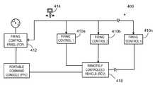
- remote digital firing system 400uses a single digital code plug 412 for storing one-time random session variables for each firing circuit 410 , reducing the number of digital code plugs to one per remote controlled vehicle 418 .
- Remote digital firing system 500has two remotely controlled vehicles 518 a and 518 b having firing control circuits 510 a - 510 n and 511 a - 511 n mounted thereto, respectively.
- Digital code plug 514 acarries one time session variables for firing control circuits 510 and digital code plug 514 b carries one time session variables for firing control circuits 511 .
- a single firing control panel 512 with the appropriate digital code plugoperates each firing control circuit.
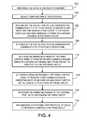
- a method 600 of operating a remote digital firing systemis shown.
- a first digital code plugis integrated at 602 in communicative combination with at least two of a first set of firing circuits. Each integration involves generating a group of one-time random session variables for the firing circuit, writing the session variables to the first digital code plug, and simultaneously storing the session variables in the firing circuit.
- a local messageis generated at 604 when the first digital code plug is integrated in communicative combination with a firing circuit and transmitted at 606 to the firing circuit's host to notify it that the first digital code plug is integrated with the firing circuit.
- the first digital code plugis then separated at 608 from communicative combination with the firing circuit.
- a local messageis generated at 610 and transmitted at 612 to the host to notify it that the first digital code plug is no longer integrated.
- a second digital code plugis integrated at 614 in communicative combination with at least two of a second set of firing circuits.
- the second setis mounted to a different host (e.g., a remotely controlled vehicle) than the first set.
- Each integrationincludes generating a group of one-time random session variables for the firing circuit, writing the session variables to the second digital code plug, and simultaneously storing the session variables in the firing circuit.
- a local messageis generated at 616 when the second digital code plug is integrated in communicative combination with a firing circuit and transmitted at 618 to the firing circuit's host to notify it that the second digital code plug is integrated with the firing circuit.
- the second digital code plugis then separated at 620 from communicative combination with the firing circuit. At that time a local message is generated at 622 and transmitted at 624 to the host to notify it that the second digital code plug is no longer integrated.
- the first digital code plugis integrated at 626 in communicative combination with the firing control panel.
- a local messageis generated at 628 and transmitted at 630 to the firing control panel's host to notify the host that the first digital code plug has been integrated.
- a userselects at 632 a first remote mission payload and corresponding first firing circuit to be controlled by the firing control panel.
- the useractuates an arming mechanism of the firing control panel at 634 to transmit an ARM command message embodying a session variable for the first firing circuit and read from the first digital code plug to arm the first firing circuit.
- the userthen actuates a firing mechanism of the firing control panel at 636 to transmit a first FIRE message embodying another session variable for the first firing circuit and read from the first digital code plug to activate the first firing circuit to fire the first remote mission payload.
- the methodis then repeated with the second digital code plug, starting at 626 .
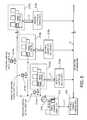
- a method 700 of operating a remote digital firing systemis shown.
- the digital code plugis integrated at 702 in communicative combination with a first firing circuit to generate first one-time random session variables, which are written to the digital code plug and stored in the first firing circuit.
- a local messageis generated at 704 and transmitted at 706 to a host to notify it that the digital code plug is integrated with the firing circuit.
- the digital code plugis separated at 708 from the first firing circuit, generating at 710 and transmitting at 712 a local message to the host of the first firing circuit to notify the host that the digital code plug is not integrated with the firing circuit.
- the digital code plugis integrated at 726 in communicative combination with the firing control panel.
- a local messageis generated at 728 and transmitted at 730 to the host of the firing control panel to notify the host that the digital code plug is integrated with the second firing circuit.
- a userselects at 732 the first remote mission payload to be controlled by the firing control panel.
- An arming mechanismis actuated at 734 to transmit an ARM command message embodying one first session variable read from the digital code plug to arm the first firing circuit.
- the useractuates at 736 a firing mechanism to transmit a first FIRE message embodying another first session variable read from the digital code plug to activate the first firing circuit to fire the first remote mission payload.
- a userselects at 738 a second remote mission payload to be controlled by the firing control panel.
- An arming mechanismis actuated at 740 to transmit an ARM command message embodying one second session variable read from the digital code plug to arm the second firing circuit.
- the useractuates at 742 a firing mechanism to transmit a second FIRE message embodying another second session variable read from the digital code plug to activate the second firing circuit to fire the second remote mission payload.
- the digital code plugis then separated from the firing control panel at 744 , whereby a local message is generated at 746 and transmitted at 748 to a host of the firing control panel to notify the host that the digital code plug is no longer integrated with the firing control panel.
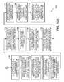
- a method 760 for hiding the intent of an operator of a remote digital firing system for firing a remote mission payloadis shown.
- a first encrypted heartbeat status request messageis generated at 762 containing a quantity of data that is the same as the quantity of data contained in encrypted arm, fire, and safe/disarm messages.
- the first encrypted heartbeat status request messageis transmitted at 764 .
- a second encrypted heartbeat status request messageis generated at 768 , also containing a quantity of data that is the same as the quantity of data contained in encrypted arm, fire, and safe/disarm messages, and transmitted at 770 .
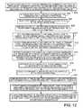
- a method of a method 800 of operating a remote digital firing systemthat includes first and second firing circuits, first and second digital code plugs, and a firing control panel to fire first and second remote mission payloads communicatively coupled to the first and second firing circuits, is shown.
- the first digital code plugis integrated at 802 in communicative combination with the first firing circuit to generate and write first one-time random session variables and a first remote mission payload identifier to the first digital code plug and simultaneously storing the session variables in the first firing circuit.
- the first digital code plugis integrated at 804 in communicative combination with the firing control panel and the first remote mission payload to be controlled by the firing control panel is selected at 806 .
- the selection of the first remote mission payloadis compared at 808 with the first remote mission payload identifier read from the first digital code plug.
- An arming mechanismis actuated at 810 to transmit an ARM command message embodying one first session variable read from the first digital code plug to arm the first firing circuit.
- a firing mechanismis actuated at 812 to transmit a first FIRE command message embodying another first session variable read from the first digital code plug to activate the first firing circuit to fire the first remote mission payload.
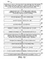
- a remote digital firing systemis provided at 852 , including a firing circuit, a digital code plug, and a firing control panel to fire a remote mission payload communicatively coupled to the firing circuit.
- a messagecomprising information about an error made by the firing circuit and a possible cause of the error is generated and encrypted at the firing circuit and transmitted at 856 to the firing control panel.
- the messageis decrypted 858 at the control panel a parsable local message is generated at 860 and displayed to a user at 862 and recorded in a log at 864 .
- the processis repeated for the second firing circuit at 866 - 876 .
- the operator of the remote digital firing systemdoesn't have to be present at the firing circuits to diagnose problems.
Landscapes
- Engineering & Computer Science (AREA)
- General Engineering & Computer Science (AREA)
- Selective Calling Equipment (AREA)
Abstract
Description
- (i) determine if the
digital code plug 40 has been integrated in communicative combination with thefiring circuit 20; - (ii) parse incoming message characters;
- (iii) update condition of the status indicators;
- (iv) update internal counters;
- (v) check hardware status against the current state of the
firing circuit 20 implemented via the instruction sets of theapplication module 23; and - (vi) generate a time based entropy source for random number generation by counting rapidly while idle and waiting for the next iteration of the loop.
- (i) determine if the
- (i) the
firing mechanism 35 is actuated and thearming mechanism 33 is in the safe position; - (ii) the
firing mechanism 35 is actuated while the link-test mechanism 33 is actuated; - (iii) the
arming mechanism 34 is left in the armed position for more than the predetermined time interval (see paragraph (9a); - (iv) the link-
test mechanism 33 is actuated while thearming mechanism 34 is in the armed position; and - (v) the link-
test mechanism 33 is actuated while thefiring mechanism 35 is actuated.
- (i) the
| TABLE I | |
| MESSAGE TYPE | DATA BLOCK FORMAT |
| M1. Request for | 32 bits (unspecified) |
| Challenge | 16 bits (random number) |
| 16 bits (unspecified) | |
| M2. Challenge | 16 bits (random number challenge) |
| 16 bits (unspecified) | |
| 16 bits (random number - from Request Msg) | |
| 16 bits (unspecified) | |
| M3. SAFE/ | 32 bits (SAFE/DISARM code - read from digital |
| Command | code plug 40) |
| 8 bits (rolling code sequence - read from digital | |
| code plug 40) | |
| 16 bits (random challenge number - from | |
| Challenge Msg) | |
| 8 bits (unspecified) | |
| M4. SAFE/DISARM | 16 bits (random challenge number - from SAFE/ |
| Verification | DISARM Command Msg) |
| M5. | 32 bits (ARM code - read from digital code plug |
| 40) | |
| 16 bits (random challenge number - from | |
| Challenge Msg) | |
| 16 bits (unspecified) | |
| M6. ARM Verification | 16 bits (random challenge number - from ARM |
| Command Msg) | |
| M7. | 32 bits (FIRE code - read from digital code plug |
| 40) | |
| 16 bits (random challenge number - from | |
| Challenge Msg) | |
| 16 bits (unspecified) | |
| M8. FIRE Verification | 16 bits (random challenge number - from FIRE |
| Command Msg) | |
| TABLE II | |||
| ACTION | MSG ID | MESSAGE FORMAT | DESCRIPTION |
 | @0K | Status Message - | |
| of digital code | see paragraphs | ||
| plug 40 in | (a), (b), and (c) | ||
| communicative | |||
| combination | |||
| with the | |||
| circuit | |||
| 20 | |||
 | @0k | Status Message - | |
| of the digital | see paragraphs | ||
| code plug 40 | (a), (b), and (c) | ||
| from | |||
| communicative | |||
| combination | |||
| with the | |||
| circuit | |||
| 20 | |||
 | $0K | See paragraphs | |
| of digital code | (a), (b), and (c) | ||
| plug 40 in | |||
| communicative | |||
| combination | |||
| with the | |||
| control panel | |||
| 30 | |||
 | $0K | See paragraphs | |
| of the digital | (a), (b), and (c) | ||
| code plug 40 | |||
| from | |||
| communicative | |||
| combination | |||
| with the | |||
| firing circuit | |||
| 20 | |||
 | M3 | $0SFEDCBA9876543210 | See paragraphs |
| of digital code | (i), (j), (k), and | ||
| plug 40 in | (m) | ||
| communicative | |||
| combination | |||
| with the firing | |||
| control panel 30 | |||
| (or actuation | |||
| of the link- | |||
| mechanism | |||
| 33 | |||
| or deactuation | |||
| of the arming | |||
| mechanism 34) | |||
| Validation of | M4 | @0VSFEDC | See paragraphs |
| the SAFE/ | (i), (j), (k), and | ||
| DISARM | (m) | ||
| command | |||
| message M3 | |||
 | M1 | $0RFEDCBA9876543210 | See paragraphs |
| of the arming | (i), (j), (l), (m), | ||
| and (o) | |||
| Response to a | M2 | @0CFEDCBA9876543210 | See paragraphs |
| Request-for- | (i), (j), (l), (m), | ||
| Challenge | (n), and (o) | ||
| message M1 | |||
| Validation of | M5 | $0AFEDCBA9876543210 | See paragraphs |
| the Challenge | (i), (j), (m), (n), | ||
| message M2 - | and (o) | ||
| automatic | |||
| transmittal of | |||
| the ARM | |||
| command | |||
| message | |||
| Validation of | M6 | @0VAFEDC | See paragraphs |
| the ARM | (i), (j), (n), and | ||
| command | (o) | ||
| message M5 - | |||
| firing | |||
| 20 transitioned | |||
| to the armed | |||
| state | |||
 | M1 | $0RFEDCBA9876543210 | See paragraphs |
| of the firing | (i), (j), (l), (m), | ||
| and (o) | |||
| Response to a | M2 | @0CFEDCBA9876543210 | See paragraphs |
| Request-for- | (i), (j), (l), (m), | ||
| Challenge | (n), and (o) | ||
| message M1 | |||
| Validation of | M7 | $0FFEDCBA9876543210 | See paragraphs |
| the Challenge | (i), (j), (m), (n), | ||
| message M2 - | and (o) | ||
| automatic | |||
| transmittal | |||
| of the FIRE | |||
| command | |||
| message | |||
| Validation of | M8 | @0VFFEDC | See paragraphs |
| the FIRE | (i), (j), (n), and | ||
| command | (o) | ||
| message M7 - | |||
| firing | |||
| 20 activated | |||
| (fired) | |||
| TABLE III |
| Commands from Control Panel to Firing Circuit |
| Safe (disarm) command | 8 | bit protocol version (4) |
| 8 | bit command character (“S”) | |
| 8 | bit packet sequence lower byte | |
| (random on plug insertion) | ||
| 8 | bit packet sequence upper byte | |
| (zeroed on plug insertion) | ||
| 32 | bit safe code (“SAFE”) | |
| Status Request (Heartbeat) | 8 | bit protocol version (4) |
| Command | 8 | bit command character (“H”) |
| 16 | bit packet sequence number | |
| 16 | bit heartbeat code (“HB”) | |
| 16 | bit random pad | |
| Arm Command | 8 | bit protocol version (4) |
| 8 | bit command character (“A”) | |
| 16 | bit command challenge (from most | |
| recent status) | ||
| 32 | bit Arm code read from code plug | |
| Fire Command | 8 | bit protocol version (4) |
| 8 | bit command character (“F”) | |
| 16 | bit command challenge (from most | |
| recent status) | ||
| 32 | bit Fire code read from code plug | |
| TABLE IV |
| Responses from Firing Circuit to Control Panel |
| Status (heartbeat) Response | 8 | bit protocol version (4) |
| 8 | bit status character (“S” safe, “A” | |
| armed, “s” safe error, “e” fatal error) | ||
| 16 | bit count of the number of times | |
| the system has been fired since | ||
| manufacture | ||
| 16 | bit packet sequence number (from | |
| the last command) | ||
| 16 | bit randomly generated command | |
| challenge | ||
| Information Message | 8 | bit protocol version (4) |
| 8 | bit status character (“I”) | |
| 8 | bit release number (minor version) | |
| 8 | bit version number (major version) | |
| 8 | bit error code path record (zero if no | |
| error) | ||
| 8 | bit error master mode record | |
| 16 | bit error test record (identifies | |
| which HW components are suspect) | ||
Local Messages from Firing Circuit
Local Messages from Firing Control Panel
| TABLE VI |
| Error Message Bits |
| 0 | Arm FET Stage 0 test (“Arm0 test”) |
| 1 | |
| 2 | Positive Relay FET test (“FETposRly”) |
| 3 | Negative Relay FET test (“FETnegRly”) |
| 4 | Plug disable check (“SYS_EN”) |
| 5 | Random number generator failure (“RNumGen”) |
| 6-11 | Unused (“Undefined”) |
| 12 | Positive relay normally closed sense (“RlyPosNC”) |
| 13 | Negative relay normally closed sense (“RlyNegNC”) |
| 14 | Positive relay normally open sense (“RlyPosNO”) |
| 15 | Negative relay normally open sense (“RlyNegNO”) |
Claims (9)
Priority Applications (2)
| Application Number | Priority Date | Filing Date | Title |
|---|---|---|---|
| US12/469,255US8109191B1 (en) | 2001-12-14 | 2009-05-20 | Remote digital firing system |
| US13/366,853US20120281829A1 (en) | 2001-12-14 | 2012-02-06 | Remote digital firing system |
Applications Claiming Priority (5)
| Application Number | Priority Date | Filing Date | Title |
|---|---|---|---|
| US34017501P | 2001-12-14 | 2001-12-14 | |
| US10/319,853US6860206B1 (en) | 2001-12-14 | 2002-12-13 | Remote digital firing system |
| US11/024,243US7143696B2 (en) | 2001-12-14 | 2004-12-28 | Remote digital firing system |
| US11/347,557US7559269B2 (en) | 2001-12-14 | 2006-02-03 | Remote digital firing system |
| US12/469,255US8109191B1 (en) | 2001-12-14 | 2009-05-20 | Remote digital firing system |
Related Parent Applications (1)
| Application Number | Title | Priority Date | Filing Date |
|---|---|---|---|
| US11/347,557DivisionUS7559269B2 (en) | 2001-12-14 | 2006-02-03 | Remote digital firing system |
Related Child Applications (1)
| Application Number | Title | Priority Date | Filing Date |
|---|---|---|---|
| US13/366,853DivisionUS20120281829A1 (en) | 2001-12-14 | 2012-02-06 | Remote digital firing system |
Publications (2)
| Publication Number | Publication Date |
|---|---|
| US20120011992A1 US20120011992A1 (en) | 2012-01-19 |
| US8109191B1true US8109191B1 (en) | 2012-02-07 |
Family
ID=46325232
Family Applications (3)
| Application Number | Title | Priority Date | Filing Date |
|---|---|---|---|
| US11/347,557Expired - Fee RelatedUS7559269B2 (en) | 2001-12-14 | 2006-02-03 | Remote digital firing system |
| US12/469,255Expired - Fee RelatedUS8109191B1 (en) | 2001-12-14 | 2009-05-20 | Remote digital firing system |
| US13/366,853AbandonedUS20120281829A1 (en) | 2001-12-14 | 2012-02-06 | Remote digital firing system |
Family Applications Before (1)
| Application Number | Title | Priority Date | Filing Date |
|---|---|---|---|
| US11/347,557Expired - Fee RelatedUS7559269B2 (en) | 2001-12-14 | 2006-02-03 | Remote digital firing system |
Family Applications After (1)
| Application Number | Title | Priority Date | Filing Date |
|---|---|---|---|
| US13/366,853AbandonedUS20120281829A1 (en) | 2001-12-14 | 2012-02-06 | Remote digital firing system |
Country Status (1)
| Country | Link |
|---|---|
| US (3) | US7559269B2 (en) |
Cited By (34)
| Publication number | Priority date | Publication date | Assignee | Title |
|---|---|---|---|---|
| US20120125218A1 (en)* | 2010-11-22 | 2012-05-24 | Battelle Energy Alliance, Llc | Apparatus, system, and method for synchronizing a removable timer key |
| US20120145786A1 (en)* | 2010-12-07 | 2012-06-14 | Bae Systems Controls, Inc. | Weapons system and targeting method |
| US20140158010A1 (en)* | 2004-01-16 | 2014-06-12 | Rothenbuhler Engineering Co. | Remote firing device with diverse initiators |
| US20170089680A1 (en)* | 2013-12-02 | 2017-03-30 | Austin Star Detonator Company | Method and apparatus for wireless blasting |
| US9811089B2 (en) | 2013-12-19 | 2017-11-07 | Aktiebolaget Electrolux | Robotic cleaning device with perimeter recording function |
| US9939529B2 (en) | 2012-08-27 | 2018-04-10 | Aktiebolaget Electrolux | Robot positioning system |
| US9946263B2 (en) | 2013-12-19 | 2018-04-17 | Aktiebolaget Electrolux | Prioritizing cleaning areas |
| US10045675B2 (en) | 2013-12-19 | 2018-08-14 | Aktiebolaget Electrolux | Robotic vacuum cleaner with side brush moving in spiral pattern |
| US10063522B2 (en) | 2013-01-25 | 2018-08-28 | Kongsberg Defence & Aerospace As | System and method for operating a safety-critical device over a non-secure communication network |
| US10149589B2 (en) | 2013-12-19 | 2018-12-11 | Aktiebolaget Electrolux | Sensing climb of obstacle of a robotic cleaning device |
| US10209080B2 (en) | 2013-12-19 | 2019-02-19 | Aktiebolaget Electrolux | Robotic cleaning device |
| US10219665B2 (en) | 2013-04-15 | 2019-03-05 | Aktiebolaget Electrolux | Robotic vacuum cleaner with protruding sidebrush |
| US10231591B2 (en) | 2013-12-20 | 2019-03-19 | Aktiebolaget Electrolux | Dust container |
| US10433697B2 (en) | 2013-12-19 | 2019-10-08 | Aktiebolaget Electrolux | Adaptive speed control of rotating side brush |
| US10448794B2 (en) | 2013-04-15 | 2019-10-22 | Aktiebolaget Electrolux | Robotic vacuum cleaner |
| US10499778B2 (en) | 2014-09-08 | 2019-12-10 | Aktiebolaget Electrolux | Robotic vacuum cleaner |
| US10518416B2 (en) | 2014-07-10 | 2019-12-31 | Aktiebolaget Electrolux | Method for detecting a measurement error in a robotic cleaning device |
| US10534367B2 (en) | 2014-12-16 | 2020-01-14 | Aktiebolaget Electrolux | Experience-based roadmap for a robotic cleaning device |
| US10617271B2 (en) | 2013-12-19 | 2020-04-14 | Aktiebolaget Electrolux | Robotic cleaning device and method for landmark recognition |
| US10678251B2 (en) | 2014-12-16 | 2020-06-09 | Aktiebolaget Electrolux | Cleaning method for a robotic cleaning device |
| US10729297B2 (en) | 2014-09-08 | 2020-08-04 | Aktiebolaget Electrolux | Robotic vacuum cleaner |
| US10877484B2 (en) | 2014-12-10 | 2020-12-29 | Aktiebolaget Electrolux | Using laser sensor for floor type detection |
| US10874271B2 (en) | 2014-12-12 | 2020-12-29 | Aktiebolaget Electrolux | Side brush and robotic cleaner |
| US10874274B2 (en) | 2015-09-03 | 2020-12-29 | Aktiebolaget Electrolux | System of robotic cleaning devices |
| US11099554B2 (en) | 2015-04-17 | 2021-08-24 | Aktiebolaget Electrolux | Robotic cleaning device and a method of controlling the robotic cleaning device |
| US11122953B2 (en) | 2016-05-11 | 2021-09-21 | Aktiebolaget Electrolux | Robotic cleaning device |
| US11169533B2 (en) | 2016-03-15 | 2021-11-09 | Aktiebolaget Electrolux | Robotic cleaning device and a method at the robotic cleaning device of performing cliff detection |
| US11274904B2 (en) | 2019-10-25 | 2022-03-15 | Aimlock Inc. | Remotely operable weapon mount |
| US11474533B2 (en) | 2017-06-02 | 2022-10-18 | Aktiebolaget Electrolux | Method of detecting a difference in level of a surface in front of a robotic cleaning device |
| US11499791B2 (en) | 2019-10-25 | 2022-11-15 | Aimlock Inc. | Trigger and safety actuating device and method therefor |
| US20230194228A1 (en)* | 2017-05-03 | 2023-06-22 | Normet Oy | A wireless electronic initiation device, an initiation arrangement and method for initiation |
| US11921517B2 (en) | 2017-09-26 | 2024-03-05 | Aktiebolaget Electrolux | Controlling movement of a robotic cleaning device |
| US11946710B1 (en)* | 2022-10-03 | 2024-04-02 | Kongsberg Defence & Aerospace As | System and method for authorizing and executing safe semi-autonomous engagement of a safety-critical device |
| US20250030576A1 (en)* | 2023-07-17 | 2025-01-23 | Tomahawk Robotics, Inc. | Layered fail-safe redundancy architecture and process for use by single data bus mobile device |
Families Citing this family (23)
| Publication number | Priority date | Publication date | Assignee | Title |
|---|---|---|---|---|
| US6263989B1 (en)* | 1998-03-27 | 2001-07-24 | Irobot Corporation | Robotic platform |
| US8375838B2 (en)* | 2001-12-14 | 2013-02-19 | Irobot Corporation | Remote digital firing system |
| US7559269B2 (en) | 2001-12-14 | 2009-07-14 | Irobot Corporation | Remote digital firing system |
| CN101253299B (en)* | 2005-07-20 | 2013-03-06 | 欧普帝姆斯特许股份公司 | Re-design of hospital operating room |
| US20100251879A1 (en)* | 2006-01-17 | 2010-10-07 | Rastegar Jahangir S | Energy harvesting power sources for assisting in the recovery/detonation of unexploded munitions governmental rights |
| KR100819801B1 (en)* | 2006-03-03 | 2008-04-07 | 삼성테크윈 주식회사 | Automatic trigger mechanism and boundary robot equipped with the same |
| US7926402B2 (en)* | 2006-11-29 | 2011-04-19 | Alliant Techsystems Inc. | Method and apparatus for munition timing and munitions incorporating same |
| US7974736B2 (en)* | 2007-04-05 | 2011-07-05 | Foster-Miller, Inc. | Robot deployed weapon system and safing method |
| CA2750713C (en)* | 2009-01-28 | 2018-03-27 | Michael John Mccann | Selective control of wireless initiation devices at a blast site |
| US8141473B2 (en)* | 2009-03-18 | 2012-03-27 | Alliant Techsystems Inc. | Apparatus for synthetic weapon stabilization and firing |
| US9032258B2 (en)* | 2012-09-14 | 2015-05-12 | Infineon Technologies Ag | Safety system challenge-and-response using modified watchdog timer |
| AU2013204965B2 (en)* | 2012-11-12 | 2016-07-28 | C2 Systems Limited | A system, method, computer program and data signal for the registration, monitoring and control of machines and devices |
| US11248895B2 (en)* | 2015-09-16 | 2022-02-15 | Orica International Pte Ltd | Wireless initiation device |
| CN105426118B (en)* | 2015-10-28 | 2018-06-05 | 浪潮(北京)电子信息产业有限公司 | A kind of method that serial ports backup heartbeat passage is utilized in double-control system |
| US9915513B1 (en) | 2017-02-05 | 2018-03-13 | Dynaenergetics Gmbh & Co. Kg | Electronic ignition circuit and method for use |
| US11307011B2 (en) | 2017-02-05 | 2022-04-19 | DynaEnergetics Europe GmbH | Electronic initiation simulator |
| US11053782B2 (en) | 2018-04-06 | 2021-07-06 | DynaEnergetics Europe GmbH | Perforating gun system and method of use |
| US11408279B2 (en) | 2018-08-21 | 2022-08-09 | DynaEnergetics Europe GmbH | System and method for navigating a wellbore and determining location in a wellbore |
| US11661824B2 (en) | 2018-05-31 | 2023-05-30 | DynaEnergetics Europe GmbH | Autonomous perforating drone |
| US20240361115A1 (en)* | 2021-08-24 | 2024-10-31 | Orica International Pte Ltd | Safety systems for commercial blasting operations |
| PL4235085T3 (en) | 2022-02-25 | 2025-06-09 | John Cockerill Defense S.A. | Secure remote operation unit for a weapon system |
| IL293692B2 (en)* | 2022-06-08 | 2025-09-01 | Gate Tech Ltd | Detonation control systems utilizing a smrt safety pin |
| US20240301845A1 (en)* | 2023-01-31 | 2024-09-12 | Gary C. Rosenfield | Systems, methods and devices for controlling ignition and launches |
Citations (114)
| Publication number | Priority date | Publication date | Assignee | Title |
|---|---|---|---|---|
| US3711638A (en) | 1971-02-02 | 1973-01-16 | J Davies | Remote monitoring and weapon control system |
| US3828458A (en) | 1973-06-11 | 1974-08-13 | Palmer J Skone | Remotely operable trigger actuator |
| US3888181A (en) | 1959-09-10 | 1975-06-10 | Us Army | Munition control system |
| US4012860A (en) | 1975-05-28 | 1977-03-22 | Auger Arnold J | Adjustable rifle rest |
| US4196653A (en) | 1978-08-21 | 1980-04-08 | Cadillac Gage Company | Auxiliary firing mechanism |
| US4205589A (en) | 1977-10-14 | 1980-06-03 | Engler Richard D | Weapon control and firing system |
| US4234850A (en) | 1979-01-08 | 1980-11-18 | Optimizer Control Corporation | Firing time control circuit |
| US4253132A (en) | 1977-12-29 | 1981-02-24 | Cover John H | Power supply for weapon for immobilization and capture |
| US4256013A (en) | 1979-03-30 | 1981-03-17 | Quitadama Dominick J | Multiple target weapons system |
| EP0076960A2 (en)* | 1981-10-10 | 1983-04-20 | Hüls Troisdorf Aktiengesellschaft | Land mine for use at short or long range |
| EP0175854A1 (en)* | 1984-07-28 | 1986-04-02 | Dynamit Nobel Aktiengesellschaft | Blocking device for mine sensors |
| US4674047A (en) | 1984-01-31 | 1987-06-16 | The Curators Of The University Of Missouri | Integrated detonator delay circuits and firing console |
| US4682435A (en) | 1986-03-14 | 1987-07-28 | James Heltzel | Safety system for disabling a firearm |
| US4685396A (en) | 1984-09-04 | 1987-08-11 | Imperial Chemical Industries Plc | Method and apparatus for safer remotely controlled firing of ignition elements |
| DE3317376C2 (en) | 1983-05-13 | 1987-12-03 | Diehl Gmbh & Co, 8500 Nuernberg, De | |
| US4718187A (en) | 1986-10-02 | 1988-01-12 | Electronic Warfare Associates, Inc. | Trigger means for a weapon control system |
| US4869008A (en) | 1987-11-12 | 1989-09-26 | Bull-Pup Industries, Inc. | Replacement gun stock unit |
| US4884506A (en) | 1986-11-06 | 1989-12-05 | Electronic Warfare Associates, Inc. | Remote detonation of explosive charges |
| US5020411A (en) | 1989-03-06 | 1991-06-04 | Larry Rowan | Mobile assault logistic kinetmatic engagement device |
| EP0433697A2 (en) | 1989-12-21 | 1991-06-26 | Hughes Aircraft Company | Modular, electronic safe-arm device |
| US5090321A (en) | 1985-06-28 | 1992-02-25 | Ici Australia Ltd | Detonator actuator |
| US5272955A (en) | 1992-07-17 | 1993-12-28 | Bond Robert L | Gun aiming device for a wheelchair |
| US5359576A (en) | 1992-01-17 | 1994-10-25 | The Computer Learning Works, Inc. | Voice activated target launching system with automatic sequencing control |
| US5442358A (en) | 1991-08-16 | 1995-08-15 | Kaman Aerospace Corporation | Imaging lidar transmitter downlink for command guidance of underwater vehicle |
| US5520114A (en) | 1992-09-17 | 1996-05-28 | Davey Bickford | Method of controlling detonators fitted with integrated delay electronic ignition modules, encoded firing control and encoded ignition module assembly for implementation purposes |
| US5563366A (en) | 1989-10-10 | 1996-10-08 | Joanell Laboratories, Inc. | Pyrotechnic ignition apparatus |
| US5636464A (en) | 1996-08-22 | 1997-06-10 | Ciluffo; Gary | Audio controlled gun locking mechanism with gun identification storage and retrieval capability |
| US5764888A (en) | 1995-07-20 | 1998-06-09 | Dallas Semiconductor Corporation | Electronic micro identification circuit that is inherently bonded to someone or something |
| US5767437A (en) | 1997-03-20 | 1998-06-16 | Rogers; Donald L. | Digital remote pyrotactic firing mechanism |
| US5924232A (en) | 1997-07-11 | 1999-07-20 | Programmable Safety Systems Corporation | Intelligent firearm safety mechanism |
| US5949015A (en) | 1997-05-14 | 1999-09-07 | Kollmorgen Corporation | Weapon control system having weapon stabilization |
| US5953844A (en) | 1998-12-01 | 1999-09-21 | Quantum Leap Research Inc. | Automatic firearm user identification and safety module |
| US5966859A (en) | 1997-11-14 | 1999-10-19 | Samuels; Mark A. | Devices and methods for controlled manual and automatic firearm operation |
| US6009791A (en) | 1998-06-05 | 2000-01-04 | Medlin; Richard C. | Armored vehicle with a retractable weapon platform system |
| WO2000026607A1 (en)* | 1998-10-29 | 2000-05-11 | Dynamit Nobel Gmbh Explosivstoff- Und Systemtechnik | Detonation system for detonators which can be tripped by radio, and a method for tripping these detonators |
| US6113343A (en) | 1996-12-16 | 2000-09-05 | Goldenberg; Andrew | Explosives disposal robot |
| US6154694A (en) | 1998-05-11 | 2000-11-28 | Kabushiki Kaisha Tokai Rika Denki Seisakusho | Data carrier system |
| US6173651B1 (en) | 1996-05-24 | 2001-01-16 | Davey Bickford | Method of detonator control with electronic ignition module, coded blast controlling unit and ignition module for its implementation |
| US6223461B1 (en) | 1998-11-12 | 2001-05-01 | Technology Patents, Llc | Firearm with remotely activated safety system |
| US6237462B1 (en) | 1998-05-21 | 2001-05-29 | Tactical Telepresent Technolgies, Inc. | Portable telepresent aiming system |
| US6250194B1 (en) | 1997-03-17 | 2001-06-26 | Heckler & Koch Gmbh | Multipurpose weapon |
| US6269730B1 (en) | 1999-10-22 | 2001-08-07 | Precision Remotes, Inc. | Rapid aiming telepresent system |
| US6283034B1 (en) | 1999-07-30 | 2001-09-04 | D. Wayne Miles, Jr. | Remotely armed ammunition |
| US6286242B1 (en) | 1998-12-04 | 2001-09-11 | Smith & Wesson Corp. | Security apparatus for a firearm |
| US20010033228A1 (en) | 1997-01-16 | 2001-10-25 | Boaz Kisreman | Novel smart holster |
| US20010043509A1 (en) | 1995-10-20 | 2001-11-22 | Baker Hughes Incorporated | Method and apparatus for improved communication in a wellbore utilizing acoustic signals |
| US20010045883A1 (en) | 2000-04-03 | 2001-11-29 | Holdaway Charles R. | Wireless digital launch or firing system |
| US6332400B1 (en) | 2000-01-24 | 2001-12-25 | The United States Of America As Represented By The Secretary Of The Navy | Initiating device for use with telemetry systems |
| US6412207B1 (en) | 1998-06-24 | 2002-07-02 | Caleb Clark Crye | Firearm safety and control system |
| US6449892B1 (en) | 2001-06-18 | 2002-09-17 | Xybernaut Corporation | Smart weapon |
| US6490977B1 (en) | 1998-03-30 | 2002-12-10 | Magicfire, Inc. | Precision pyrotechnic display system and method having increased safety and timing accuracy |
| US20030028257A1 (en) | 2001-08-06 | 2003-02-06 | Crawford Daniel A. | Actuator controller for selecting a communication language |
| US6535793B2 (en) | 2000-05-01 | 2003-03-18 | Irobot Corporation | Method and system for remote control of mobile robot |
| US20030074823A1 (en) | 2001-09-25 | 2003-04-24 | Amos Golan | Firearm assembly |
| US6557104B2 (en) | 1997-05-02 | 2003-04-29 | Phoenix Technologies Ltd. | Method and apparatus for secure processing of cryptographic keys |
| US6624744B1 (en) | 2001-10-05 | 2003-09-23 | William Neil Wilson | Golf cart keyless control system |
| WO2004020934A1 (en)* | 2002-08-30 | 2004-03-11 | Orica Explosives Technology Pty Ltd. | Access control for electronic blasting machines |
| US20040050240A1 (en) | 2000-10-17 | 2004-03-18 | Greene Ben A. | Autonomous weapon system |
| US6839662B2 (en) | 2001-08-17 | 2005-01-04 | Lockheed Martin Corporation | Command and control system architecture for convenient upgrading |
| US6860206B1 (en) | 2001-12-14 | 2005-03-01 | Irobot Corporation | Remote digital firing system |
| US20050172912A1 (en) | 2004-02-05 | 2005-08-11 | Crist Timothy J. | Control system and method for remote launchers |
| US6951071B1 (en) | 2004-08-20 | 2005-10-04 | Adelfo Acosta | Electronic rifle trigger mechanism |
| US20050257676A1 (en) | 2003-10-23 | 2005-11-24 | Ealovega George D | Weapon with electro-mechanical firing mechanism for use with combination percussive and electrically responsive cartridge primer |
| US20050262992A1 (en) | 2002-09-03 | 2005-12-01 | Wolfgang Becker | Device for electrically controlling an automatic weapon |
| US20060011082A1 (en) | 2004-01-16 | 2006-01-19 | Jacobson Thomas L | Remote firing system |
| US20060027127A1 (en) | 2004-07-14 | 2006-02-09 | Taser International, Inc. | Systems and methods having a power supply in place of a round of ammunition |
| US20060044146A1 (en) | 2004-08-25 | 2006-03-02 | Caterpillar Inc. | Systems and methods for radio frequency trigger |
| US7092867B2 (en) | 2000-12-18 | 2006-08-15 | Bae Systems Land & Armaments L.P. | Control system architecture for a multi-component armament system |
| US7159500B2 (en) | 2004-10-12 | 2007-01-09 | The Telerobotics Corporation | Public network weapon system and method |
| US20070044673A1 (en) | 2005-03-18 | 2007-03-01 | Dirk Hummel | Wireless detonator assembly, and methods of blasting |
| US20070072662A1 (en) | 2005-09-28 | 2007-03-29 | Templeman James N | Remote vehicle control system |
| US20070074438A1 (en) | 2003-11-21 | 2007-04-05 | Stefan Parhofer | Safety device for weapons and method for securing weapons provided with a safety device |
| US20070097592A1 (en) | 1999-09-17 | 2007-05-03 | Taser International, Inc. | Electrical weapon having controller for timed current through target and date/time recording |
| US20070105070A1 (en) | 2005-11-08 | 2007-05-10 | Luther Trawick | Electromechanical robotic soldier |
| US20070119326A1 (en) | 2001-12-14 | 2007-05-31 | Rudakevych Pavlo E | Remote digital firing system |
| US7228261B2 (en) | 2003-08-13 | 2007-06-05 | The Boeing Company | Methods and apparatus for testing and diagnosis of weapon control systems |
| US20070124979A1 (en) | 2004-06-18 | 2007-06-07 | Newkirk Reginald H | Gun with user notification |
| US20070156286A1 (en) | 2005-12-30 | 2007-07-05 | Irobot Corporation | Autonomous Mobile Robot |
| US20070180749A1 (en) | 2004-05-26 | 2007-08-09 | Michael Schumacher | Weapons firing safeties and methods of operating the same |
| US20070204745A1 (en) | 2006-03-03 | 2007-09-06 | Samsung Techwin Co., Ltd. | Automatic shooting mechanism and robot having the same |
| US20070209501A1 (en) | 2006-03-03 | 2007-09-13 | Samsung Techwin Co., Ltd. | Actuation mechanism having two degrees of freedom and sentry robot having the same |
| US7275691B1 (en) | 2003-11-25 | 2007-10-02 | Curtis Wright | Artillery fire control system |
| US7339456B1 (en) | 1999-03-15 | 2008-03-04 | Buckley Jonathan D | Electromechanical safety system for a firearm |
| US20080053300A1 (en) | 2004-06-03 | 2008-03-06 | Eyal Berkovich | Gun Mount |
| US20080083344A1 (en) | 2005-11-14 | 2008-04-10 | Deguire Daniel R | Safe and arm system for a robot |
| US7370583B2 (en)* | 2002-03-11 | 2008-05-13 | Dyno Nobel Sweden Ab | Detonator system and method in connection with the same |
| US20080121097A1 (en) | 2001-12-14 | 2008-05-29 | Irobot Corporation | Remote digital firing system |
| US20080134555A1 (en) | 2006-12-12 | 2008-06-12 | Werner Theodore J | Gas-dampened recoil rest with remote trigger release for a rifle for allowing a shooter to fire the rifle without any human contact and possible motion contamination |
| US20080202326A1 (en) | 2006-08-24 | 2008-08-28 | Carroll Alf L | Weapon mount |
| US20080307993A1 (en) | 2004-11-02 | 2008-12-18 | Orica Explosives Technology Pty Ltd | Wireless Detonator Assemblies, Corresponding Blasting Apparatuses, and Methods of Blasting |
| US7471216B2 (en) | 2004-11-17 | 2008-12-30 | Ultra Electronics Measurement Systems, Inc. | Handheld controller for vehicles |
| US7469623B1 (en) | 2005-03-15 | 2008-12-30 | The United States Of America As Represented By The Secretary Of The Army | Remote firing mechanism to enable firing remotely from a weapon breech |
| US20090107024A1 (en) | 2007-10-31 | 2009-04-30 | Stefan Doll | Slide, stop, trigger device and handle for a weapon |
| US20090164045A1 (en) | 2007-12-19 | 2009-06-25 | Deguire Daniel R | Weapon robot with situational awareness |
| US20090158922A1 (en) | 2007-12-19 | 2009-06-25 | Werner Theodore J | Device for wirelessly and remotely actuating a trigger of a weapon |
| US20090205237A1 (en) | 2006-05-31 | 2009-08-20 | Giora Gorali | Electric safety device actuator |
| US20090223104A1 (en) | 2006-03-08 | 2009-09-10 | Famiglia Anzeloni S.R.L. | Safety Device for Firearm and Remote Control System of One or More Fire-Arms Provided with Said Device |
| US20090241763A1 (en) | 2007-06-22 | 2009-10-01 | Revord Raoul D | Multi-party missile firing control system |
| US20090255160A1 (en) | 2008-04-11 | 2009-10-15 | James Summers | Weapon control device |
| US20090281676A1 (en) | 2008-04-16 | 2009-11-12 | Beavis Russell H | Systems, Apparatus, and Methods for the Management and Control of Remotely Controlled Devices |
| US20090300961A1 (en) | 2007-01-21 | 2009-12-10 | Alfons Ruhland | Bolt action part for elecrical or laser-based cartridge |
| US20100107464A1 (en) | 2007-04-24 | 2010-05-06 | Rudi Beckmann | Trigger apparatus for use with firearms |
| US20100117888A1 (en) | 2007-02-12 | 2010-05-13 | Alexander Simon | Method and Apparatus for Defending Against Airborne Ammunition |
| US7748324B2 (en) | 2003-02-21 | 2010-07-06 | Sutcliffe Scott A | Method to ensure payload activation of ordnance |
| US20100175547A1 (en) | 2008-11-21 | 2010-07-15 | Brian Hoffman | Reciprocally-cycled, externally-actuated weapon |
| US7783387B2 (en) | 2005-04-19 | 2010-08-24 | Comau S.P.A. | Process for controlling industrial robots, and related robots, systems and computer programs |
| US20100212482A1 (en) | 2007-04-18 | 2010-08-26 | Morin Gary R | Firing pin assembly |
| US7788476B2 (en) | 2006-08-08 | 2010-08-31 | Siemens Industry, Inc. | Devices, systems, and methods for initializing a PLC module |
| US20100251880A1 (en) | 2007-04-20 | 2010-10-07 | Kongsberg Defence & Aerospace As | Firearm remote cocking method and arrangement |
| US20100257769A1 (en) | 2007-10-08 | 2010-10-14 | Stefan Doll | Safety apparatus for firearms |
| US20100263524A1 (en) | 2007-04-05 | 2010-10-21 | Morin Gary R | Robot deployed weapon system and safing method |
| US20100275768A1 (en) | 2002-11-26 | 2010-11-04 | Eos Defense Systems, Inc. | Dual elevation weapon station and method of use |
| USRE41916E1 (en) | 1998-05-14 | 2010-11-09 | Round Rock Research, Llc | Wireless communication systems, interfacing devices, communication methods, methods of interfacing with an interrogator, and methods of operating an interrogator |
| US20110005847A1 (en) | 2007-12-14 | 2011-01-13 | Andrus Lance L | Modular mobile robot |
- 2006
- 2006-02-03USUS11/347,557patent/US7559269B2/ennot_activeExpired - Fee Related
- 2009
- 2009-05-20USUS12/469,255patent/US8109191B1/ennot_activeExpired - Fee Related
- 2012
- 2012-02-06USUS13/366,853patent/US20120281829A1/ennot_activeAbandoned
Patent Citations (130)
| Publication number | Priority date | Publication date | Assignee | Title |
|---|---|---|---|---|
| US3888181A (en) | 1959-09-10 | 1975-06-10 | Us Army | Munition control system |
| US3711638A (en) | 1971-02-02 | 1973-01-16 | J Davies | Remote monitoring and weapon control system |
| US3828458A (en) | 1973-06-11 | 1974-08-13 | Palmer J Skone | Remotely operable trigger actuator |
| US4012860A (en) | 1975-05-28 | 1977-03-22 | Auger Arnold J | Adjustable rifle rest |
| US4205589A (en) | 1977-10-14 | 1980-06-03 | Engler Richard D | Weapon control and firing system |
| US4253132A (en) | 1977-12-29 | 1981-02-24 | Cover John H | Power supply for weapon for immobilization and capture |
| US4196653A (en) | 1978-08-21 | 1980-04-08 | Cadillac Gage Company | Auxiliary firing mechanism |
| US4234850A (en) | 1979-01-08 | 1980-11-18 | Optimizer Control Corporation | Firing time control circuit |
| US4256013A (en) | 1979-03-30 | 1981-03-17 | Quitadama Dominick J | Multiple target weapons system |
| EP0076960A2 (en)* | 1981-10-10 | 1983-04-20 | Hüls Troisdorf Aktiengesellschaft | Land mine for use at short or long range |
| DE3317376C2 (en) | 1983-05-13 | 1987-12-03 | Diehl Gmbh & Co, 8500 Nuernberg, De | |
| US4674047A (en) | 1984-01-31 | 1987-06-16 | The Curators Of The University Of Missouri | Integrated detonator delay circuits and firing console |
| EP0175854A1 (en)* | 1984-07-28 | 1986-04-02 | Dynamit Nobel Aktiengesellschaft | Blocking device for mine sensors |
| US4685396A (en) | 1984-09-04 | 1987-08-11 | Imperial Chemical Industries Plc | Method and apparatus for safer remotely controlled firing of ignition elements |
| US5090321A (en) | 1985-06-28 | 1992-02-25 | Ici Australia Ltd | Detonator actuator |
| US4682435A (en) | 1986-03-14 | 1987-07-28 | James Heltzel | Safety system for disabling a firearm |
| US4718187A (en) | 1986-10-02 | 1988-01-12 | Electronic Warfare Associates, Inc. | Trigger means for a weapon control system |
| US4884506A (en) | 1986-11-06 | 1989-12-05 | Electronic Warfare Associates, Inc. | Remote detonation of explosive charges |
| US4869008A (en) | 1987-11-12 | 1989-09-26 | Bull-Pup Industries, Inc. | Replacement gun stock unit |
| US5020411A (en) | 1989-03-06 | 1991-06-04 | Larry Rowan | Mobile assault logistic kinetmatic engagement device |
| US5563366A (en) | 1989-10-10 | 1996-10-08 | Joanell Laboratories, Inc. | Pyrotechnic ignition apparatus |
| EP0433697A2 (en) | 1989-12-21 | 1991-06-26 | Hughes Aircraft Company | Modular, electronic safe-arm device |
| US5442358A (en) | 1991-08-16 | 1995-08-15 | Kaman Aerospace Corporation | Imaging lidar transmitter downlink for command guidance of underwater vehicle |
| US5359576A (en) | 1992-01-17 | 1994-10-25 | The Computer Learning Works, Inc. | Voice activated target launching system with automatic sequencing control |
| US5272955A (en) | 1992-07-17 | 1993-12-28 | Bond Robert L | Gun aiming device for a wheelchair |
| US5520114A (en) | 1992-09-17 | 1996-05-28 | Davey Bickford | Method of controlling detonators fitted with integrated delay electronic ignition modules, encoded firing control and encoded ignition module assembly for implementation purposes |
| US5764888A (en) | 1995-07-20 | 1998-06-09 | Dallas Semiconductor Corporation | Electronic micro identification circuit that is inherently bonded to someone or something |
| US20010043509A1 (en) | 1995-10-20 | 2001-11-22 | Baker Hughes Incorporated | Method and apparatus for improved communication in a wellbore utilizing acoustic signals |
| US6173651B1 (en) | 1996-05-24 | 2001-01-16 | Davey Bickford | Method of detonator control with electronic ignition module, coded blast controlling unit and ignition module for its implementation |
| US5636464A (en) | 1996-08-22 | 1997-06-10 | Ciluffo; Gary | Audio controlled gun locking mechanism with gun identification storage and retrieval capability |
| US6113343A (en) | 1996-12-16 | 2000-09-05 | Goldenberg; Andrew | Explosives disposal robot |
| US20010033228A1 (en) | 1997-01-16 | 2001-10-25 | Boaz Kisreman | Novel smart holster |
| US6250194B1 (en) | 1997-03-17 | 2001-06-26 | Heckler & Koch Gmbh | Multipurpose weapon |
| US5767437A (en) | 1997-03-20 | 1998-06-16 | Rogers; Donald L. | Digital remote pyrotactic firing mechanism |
| US6557104B2 (en) | 1997-05-02 | 2003-04-29 | Phoenix Technologies Ltd. | Method and apparatus for secure processing of cryptographic keys |
| US5949015A (en) | 1997-05-14 | 1999-09-07 | Kollmorgen Corporation | Weapon control system having weapon stabilization |
| US5924232A (en) | 1997-07-11 | 1999-07-20 | Programmable Safety Systems Corporation | Intelligent firearm safety mechanism |
| US5966859A (en) | 1997-11-14 | 1999-10-19 | Samuels; Mark A. | Devices and methods for controlled manual and automatic firearm operation |
| US6174288B1 (en) | 1997-11-14 | 2001-01-16 | Mark A. Samuels | Devices and methods for controlled manual and automatic firearm operation |
| US6490977B1 (en) | 1998-03-30 | 2002-12-10 | Magicfire, Inc. | Precision pyrotechnic display system and method having increased safety and timing accuracy |
| US6154694A (en) | 1998-05-11 | 2000-11-28 | Kabushiki Kaisha Tokai Rika Denki Seisakusho | Data carrier system |
| USRE41916E1 (en) | 1998-05-14 | 2010-11-09 | Round Rock Research, Llc | Wireless communication systems, interfacing devices, communication methods, methods of interfacing with an interrogator, and methods of operating an interrogator |
| US20050066808A1 (en) | 1998-05-21 | 2005-03-31 | Precision Remotes, Inc. | Remote aiming system with video display |
| US7047863B2 (en) | 1998-05-21 | 2006-05-23 | Precision Remotes, Inc. | Remote aiming system with video display |
| US6679158B1 (en) | 1998-05-21 | 2004-01-20 | Precision Remotes, Inc. | Remote aiming system with video display |
| US6237462B1 (en) | 1998-05-21 | 2001-05-29 | Tactical Telepresent Technolgies, Inc. | Portable telepresent aiming system |
| US20070051235A1 (en) | 1998-05-21 | 2007-03-08 | Hawkes Graham S | Remote aiming system with video display |
| US6009791A (en) | 1998-06-05 | 2000-01-04 | Medlin; Richard C. | Armored vehicle with a retractable weapon platform system |
| US6412207B1 (en) | 1998-06-24 | 2002-07-02 | Caleb Clark Crye | Firearm safety and control system |
| WO2000026607A1 (en)* | 1998-10-29 | 2000-05-11 | Dynamit Nobel Gmbh Explosivstoff- Und Systemtechnik | Detonation system for detonators which can be tripped by radio, and a method for tripping these detonators |
| US6223461B1 (en) | 1998-11-12 | 2001-05-01 | Technology Patents, Llc | Firearm with remotely activated safety system |
| US5953844A (en) | 1998-12-01 | 1999-09-21 | Quantum Leap Research Inc. | Automatic firearm user identification and safety module |
| US6286242B1 (en) | 1998-12-04 | 2001-09-11 | Smith & Wesson Corp. | Security apparatus for a firearm |
| US7339456B1 (en) | 1999-03-15 | 2008-03-04 | Buckley Jonathan D | Electromechanical safety system for a firearm |
| US6283034B1 (en) | 1999-07-30 | 2001-09-04 | D. Wayne Miles, Jr. | Remotely armed ammunition |
| US20070097592A1 (en) | 1999-09-17 | 2007-05-03 | Taser International, Inc. | Electrical weapon having controller for timed current through target and date/time recording |
| US6269730B1 (en) | 1999-10-22 | 2001-08-07 | Precision Remotes, Inc. | Rapid aiming telepresent system |
| US6332400B1 (en) | 2000-01-24 | 2001-12-25 | The United States Of America As Represented By The Secretary Of The Navy | Initiating device for use with telemetry systems |
| US20010045883A1 (en) | 2000-04-03 | 2001-11-29 | Holdaway Charles R. | Wireless digital launch or firing system |
| US6535793B2 (en) | 2000-05-01 | 2003-03-18 | Irobot Corporation | Method and system for remote control of mobile robot |
| US20040050240A1 (en) | 2000-10-17 | 2004-03-18 | Greene Ben A. | Autonomous weapon system |
| US7092867B2 (en) | 2000-12-18 | 2006-08-15 | Bae Systems Land & Armaments L.P. | Control system architecture for a multi-component armament system |
| US6449892B1 (en) | 2001-06-18 | 2002-09-17 | Xybernaut Corporation | Smart weapon |
| US20030028257A1 (en) | 2001-08-06 | 2003-02-06 | Crawford Daniel A. | Actuator controller for selecting a communication language |
| US6839662B2 (en) | 2001-08-17 | 2005-01-04 | Lockheed Martin Corporation | Command and control system architecture for convenient upgrading |
| US20030074823A1 (en) | 2001-09-25 | 2003-04-24 | Amos Golan | Firearm assembly |
| US6624744B1 (en) | 2001-10-05 | 2003-09-23 | William Neil Wilson | Golf cart keyless control system |
| US7559269B2 (en) | 2001-12-14 | 2009-07-14 | Irobot Corporation | Remote digital firing system |
| US6860206B1 (en) | 2001-12-14 | 2005-03-01 | Irobot Corporation | Remote digital firing system |
| US20070119326A1 (en) | 2001-12-14 | 2007-05-31 | Rudakevych Pavlo E | Remote digital firing system |
| US20080121097A1 (en) | 2001-12-14 | 2008-05-29 | Irobot Corporation | Remote digital firing system |
| US7143696B2 (en) | 2001-12-14 | 2006-12-05 | Irobot Corporation | Remote digital firing system |
| US7370583B2 (en)* | 2002-03-11 | 2008-05-13 | Dyno Nobel Sweden Ab | Detonator system and method in connection with the same |
| US6851369B2 (en)* | 2002-08-30 | 2005-02-08 | Orica Explosives Technology Pty Ltd. | Access control for electronic blasting machines |
| WO2004020934A1 (en)* | 2002-08-30 | 2004-03-11 | Orica Explosives Technology Pty Ltd. | Access control for electronic blasting machines |
| US20050262992A1 (en) | 2002-09-03 | 2005-12-01 | Wolfgang Becker | Device for electrically controlling an automatic weapon |
| US7089844B2 (en) | 2002-09-03 | 2006-08-15 | Krauss-Maffei Wegmann Gmbh & Co. Kg | Device for electrically controlling an automatic weapon |
| US20100275768A1 (en) | 2002-11-26 | 2010-11-04 | Eos Defense Systems, Inc. | Dual elevation weapon station and method of use |
| US7748324B2 (en) | 2003-02-21 | 2010-07-06 | Sutcliffe Scott A | Method to ensure payload activation of ordnance |
| US7228261B2 (en) | 2003-08-13 | 2007-06-05 | The Boeing Company | Methods and apparatus for testing and diagnosis of weapon control systems |
| US20050257676A1 (en) | 2003-10-23 | 2005-11-24 | Ealovega George D | Weapon with electro-mechanical firing mechanism for use with combination percussive and electrically responsive cartridge primer |
| US20070074438A1 (en) | 2003-11-21 | 2007-04-05 | Stefan Parhofer | Safety device for weapons and method for securing weapons provided with a safety device |
| US7275691B1 (en) | 2003-11-25 | 2007-10-02 | Curtis Wright | Artillery fire control system |
| US20060011082A1 (en) | 2004-01-16 | 2006-01-19 | Jacobson Thomas L | Remote firing system |
| US20050172912A1 (en) | 2004-02-05 | 2005-08-11 | Crist Timothy J. | Control system and method for remote launchers |
| US20070180749A1 (en) | 2004-05-26 | 2007-08-09 | Michael Schumacher | Weapons firing safeties and methods of operating the same |
| US7600339B2 (en) | 2004-05-26 | 2009-10-13 | Heckler & Koch, Gmbh | Weapons firing safeties and methods of operating the same |
| US20080053300A1 (en) | 2004-06-03 | 2008-03-06 | Eyal Berkovich | Gun Mount |
| US20070124979A1 (en) | 2004-06-18 | 2007-06-07 | Newkirk Reginald H | Gun with user notification |
| US20060027127A1 (en) | 2004-07-14 | 2006-02-09 | Taser International, Inc. | Systems and methods having a power supply in place of a round of ammunition |
| US6951071B1 (en) | 2004-08-20 | 2005-10-04 | Adelfo Acosta | Electronic rifle trigger mechanism |
| US20060044146A1 (en) | 2004-08-25 | 2006-03-02 | Caterpillar Inc. | Systems and methods for radio frequency trigger |
| US7159500B2 (en) | 2004-10-12 | 2007-01-09 | The Telerobotics Corporation | Public network weapon system and method |
| US20080307993A1 (en) | 2004-11-02 | 2008-12-18 | Orica Explosives Technology Pty Ltd | Wireless Detonator Assemblies, Corresponding Blasting Apparatuses, and Methods of Blasting |
| US7471216B2 (en) | 2004-11-17 | 2008-12-30 | Ultra Electronics Measurement Systems, Inc. | Handheld controller for vehicles |
| US7469623B1 (en) | 2005-03-15 | 2008-12-30 | The United States Of America As Represented By The Secretary Of The Army | Remote firing mechanism to enable firing remotely from a weapon breech |
| US20080302264A1 (en) | 2005-03-18 | 2008-12-11 | Orica Explosives Technology Pty Ltd. | Wireless Detonator Assembly, and Methods of Blasting |
| US20070044673A1 (en) | 2005-03-18 | 2007-03-01 | Dirk Hummel | Wireless detonator assembly, and methods of blasting |
| US7783387B2 (en) | 2005-04-19 | 2010-08-24 | Comau S.P.A. | Process for controlling industrial robots, and related robots, systems and computer programs |
| US20070072662A1 (en) | 2005-09-28 | 2007-03-29 | Templeman James N | Remote vehicle control system |
| US20070105070A1 (en) | 2005-11-08 | 2007-05-10 | Luther Trawick | Electromechanical robotic soldier |
| US20080083344A1 (en) | 2005-11-14 | 2008-04-10 | Deguire Daniel R | Safe and arm system for a robot |
| US20070156286A1 (en) | 2005-12-30 | 2007-07-05 | Irobot Corporation | Autonomous Mobile Robot |
| US7650826B2 (en) | 2006-03-03 | 2010-01-26 | Samsung Techwin Co., Ltd. | Automatic shooting mechanism and robot having the same |
| US20070209501A1 (en) | 2006-03-03 | 2007-09-13 | Samsung Techwin Co., Ltd. | Actuation mechanism having two degrees of freedom and sentry robot having the same |
| US20070204745A1 (en) | 2006-03-03 | 2007-09-06 | Samsung Techwin Co., Ltd. | Automatic shooting mechanism and robot having the same |
| US20100083817A1 (en) | 2006-03-03 | 2010-04-08 | Samsung Techwin Co., Ltd. | Automatic shooting mechanism and robot having the same |
| US20090223104A1 (en) | 2006-03-08 | 2009-09-10 | Famiglia Anzeloni S.R.L. | Safety Device for Firearm and Remote Control System of One or More Fire-Arms Provided with Said Device |
| US20090205237A1 (en) | 2006-05-31 | 2009-08-20 | Giora Gorali | Electric safety device actuator |
| US7788476B2 (en) | 2006-08-08 | 2010-08-31 | Siemens Industry, Inc. | Devices, systems, and methods for initializing a PLC module |
| US20080202326A1 (en) | 2006-08-24 | 2008-08-28 | Carroll Alf L | Weapon mount |
| US7587854B2 (en) | 2006-12-12 | 2009-09-15 | Werner Theodore J | Gas-dampened recoil rest with remote trigger release |
| US20080134555A1 (en) | 2006-12-12 | 2008-06-12 | Werner Theodore J | Gas-dampened recoil rest with remote trigger release for a rifle for allowing a shooter to fire the rifle without any human contact and possible motion contamination |
| US20090300961A1 (en) | 2007-01-21 | 2009-12-10 | Alfons Ruhland | Bolt action part for elecrical or laser-based cartridge |
| US20100117888A1 (en) | 2007-02-12 | 2010-05-13 | Alexander Simon | Method and Apparatus for Defending Against Airborne Ammunition |
| US20100263524A1 (en) | 2007-04-05 | 2010-10-21 | Morin Gary R | Robot deployed weapon system and safing method |
| US20100212482A1 (en) | 2007-04-18 | 2010-08-26 | Morin Gary R | Firing pin assembly |
| US20100251880A1 (en) | 2007-04-20 | 2010-10-07 | Kongsberg Defence & Aerospace As | Firearm remote cocking method and arrangement |
| US20100107464A1 (en) | 2007-04-24 | 2010-05-06 | Rudi Beckmann | Trigger apparatus for use with firearms |
| US20090241763A1 (en) | 2007-06-22 | 2009-10-01 | Revord Raoul D | Multi-party missile firing control system |
| US20100257769A1 (en) | 2007-10-08 | 2010-10-14 | Stefan Doll | Safety apparatus for firearms |
| US7802511B2 (en) | 2007-10-31 | 2010-09-28 | Heckler & Koch, Gmbh | Slide, stop, trigger device and handle for a weapon |
| US20100269391A1 (en) | 2007-10-31 | 2010-10-28 | Stefan Doll | Catches and trigger apparatus for use with weapons |
| US20090107024A1 (en) | 2007-10-31 | 2009-04-30 | Stefan Doll | Slide, stop, trigger device and handle for a weapon |
| US20110005847A1 (en) | 2007-12-14 | 2011-01-13 | Andrus Lance L | Modular mobile robot |
| US20090158922A1 (en) | 2007-12-19 | 2009-06-25 | Werner Theodore J | Device for wirelessly and remotely actuating a trigger of a weapon |
| US20090164045A1 (en) | 2007-12-19 | 2009-06-25 | Deguire Daniel R | Weapon robot with situational awareness |
| US20090255160A1 (en) | 2008-04-11 | 2009-10-15 | James Summers | Weapon control device |
| US20090281676A1 (en) | 2008-04-16 | 2009-11-12 | Beavis Russell H | Systems, Apparatus, and Methods for the Management and Control of Remotely Controlled Devices |
| US20100175547A1 (en) | 2008-11-21 | 2010-07-15 | Brian Hoffman | Reciprocally-cycled, externally-actuated weapon |
Non-Patent Citations (1)
| Title |
|---|
| R. Crites; Chapter 11: Intermittent and Recirculating Packed Bed Filters; Small and Decentralized Wastewater Management Systems; 1998 pp. 703-760 WCB/McGraw-Hill NY NY. |
Cited By (44)
| Publication number | Priority date | Publication date | Assignee | Title |
|---|---|---|---|---|
| US20140158010A1 (en)* | 2004-01-16 | 2014-06-12 | Rothenbuhler Engineering Co. | Remote firing device with diverse initiators |
| US20140158008A1 (en)* | 2004-01-16 | 2014-06-12 | Rothenbuhler Engineering Co. | Remote firing device with diverse initiators |
| US9046268B2 (en) | 2005-12-07 | 2015-06-02 | Battelle Energy Alliance | Methods for synchronizing a countdown routine of a timer key and electronic device |
| US8701560B2 (en)* | 2010-11-22 | 2014-04-22 | Battelle Energy Alliance, Llc | Apparatus, system, and method for synchronizing a timer key |
| US20120125218A1 (en)* | 2010-11-22 | 2012-05-24 | Battelle Energy Alliance, Llc | Apparatus, system, and method for synchronizing a removable timer key |
| US20120145786A1 (en)* | 2010-12-07 | 2012-06-14 | Bae Systems Controls, Inc. | Weapons system and targeting method |
| US8245623B2 (en)* | 2010-12-07 | 2012-08-21 | Bae Systems Controls Inc. | Weapons system and targeting method |
| US9939529B2 (en) | 2012-08-27 | 2018-04-10 | Aktiebolaget Electrolux | Robot positioning system |
| US10063522B2 (en) | 2013-01-25 | 2018-08-28 | Kongsberg Defence & Aerospace As | System and method for operating a safety-critical device over a non-secure communication network |
| US10219665B2 (en) | 2013-04-15 | 2019-03-05 | Aktiebolaget Electrolux | Robotic vacuum cleaner with protruding sidebrush |
| US10448794B2 (en) | 2013-04-15 | 2019-10-22 | Aktiebolaget Electrolux | Robotic vacuum cleaner |
| US11009331B2 (en) | 2013-12-02 | 2021-05-18 | Austin Star Detonator Company | Method and apparatus for wireless blasting |
| US20170089680A1 (en)* | 2013-12-02 | 2017-03-30 | Austin Star Detonator Company | Method and apparatus for wireless blasting |
| US10429162B2 (en)* | 2013-12-02 | 2019-10-01 | Austin Star Detonator Company | Method and apparatus for wireless blasting with first and second firing messages |
| US10149589B2 (en) | 2013-12-19 | 2018-12-11 | Aktiebolaget Electrolux | Sensing climb of obstacle of a robotic cleaning device |
| US10209080B2 (en) | 2013-12-19 | 2019-02-19 | Aktiebolaget Electrolux | Robotic cleaning device |
| US9811089B2 (en) | 2013-12-19 | 2017-11-07 | Aktiebolaget Electrolux | Robotic cleaning device with perimeter recording function |
| US10433697B2 (en) | 2013-12-19 | 2019-10-08 | Aktiebolaget Electrolux | Adaptive speed control of rotating side brush |
| US10045675B2 (en) | 2013-12-19 | 2018-08-14 | Aktiebolaget Electrolux | Robotic vacuum cleaner with side brush moving in spiral pattern |
| US10617271B2 (en) | 2013-12-19 | 2020-04-14 | Aktiebolaget Electrolux | Robotic cleaning device and method for landmark recognition |
| US9946263B2 (en) | 2013-12-19 | 2018-04-17 | Aktiebolaget Electrolux | Prioritizing cleaning areas |
| US10231591B2 (en) | 2013-12-20 | 2019-03-19 | Aktiebolaget Electrolux | Dust container |
| US10518416B2 (en) | 2014-07-10 | 2019-12-31 | Aktiebolaget Electrolux | Method for detecting a measurement error in a robotic cleaning device |
| US10499778B2 (en) | 2014-09-08 | 2019-12-10 | Aktiebolaget Electrolux | Robotic vacuum cleaner |
| US10729297B2 (en) | 2014-09-08 | 2020-08-04 | Aktiebolaget Electrolux | Robotic vacuum cleaner |
| US10877484B2 (en) | 2014-12-10 | 2020-12-29 | Aktiebolaget Electrolux | Using laser sensor for floor type detection |
| US10874271B2 (en) | 2014-12-12 | 2020-12-29 | Aktiebolaget Electrolux | Side brush and robotic cleaner |
| US10534367B2 (en) | 2014-12-16 | 2020-01-14 | Aktiebolaget Electrolux | Experience-based roadmap for a robotic cleaning device |
| US10678251B2 (en) | 2014-12-16 | 2020-06-09 | Aktiebolaget Electrolux | Cleaning method for a robotic cleaning device |
| US11099554B2 (en) | 2015-04-17 | 2021-08-24 | Aktiebolaget Electrolux | Robotic cleaning device and a method of controlling the robotic cleaning device |
| US10874274B2 (en) | 2015-09-03 | 2020-12-29 | Aktiebolaget Electrolux | System of robotic cleaning devices |
| US11712142B2 (en) | 2015-09-03 | 2023-08-01 | Aktiebolaget Electrolux | System of robotic cleaning devices |
| US11169533B2 (en) | 2016-03-15 | 2021-11-09 | Aktiebolaget Electrolux | Robotic cleaning device and a method at the robotic cleaning device of performing cliff detection |
| US11122953B2 (en) | 2016-05-11 | 2021-09-21 | Aktiebolaget Electrolux | Robotic cleaning device |
| US20230194228A1 (en)* | 2017-05-03 | 2023-06-22 | Normet Oy | A wireless electronic initiation device, an initiation arrangement and method for initiation |
| US12018925B2 (en)* | 2017-05-03 | 2024-06-25 | Normet Oy | Wireless electronic initiation device, an initiation arrangement and method for initiation |
| US11474533B2 (en) | 2017-06-02 | 2022-10-18 | Aktiebolaget Electrolux | Method of detecting a difference in level of a surface in front of a robotic cleaning device |
| US11921517B2 (en) | 2017-09-26 | 2024-03-05 | Aktiebolaget Electrolux | Controlling movement of a robotic cleaning device |
| US11499791B2 (en) | 2019-10-25 | 2022-11-15 | Aimlock Inc. | Trigger and safety actuating device and method therefor |
| US11274904B2 (en) | 2019-10-25 | 2022-03-15 | Aimlock Inc. | Remotely operable weapon mount |
| US12031798B2 (en) | 2019-10-25 | 2024-07-09 | Aimlock Inc. | Remotely operable weapon mount |
| US11946710B1 (en)* | 2022-10-03 | 2024-04-02 | Kongsberg Defence & Aerospace As | System and method for authorizing and executing safe semi-autonomous engagement of a safety-critical device |
| US20240110756A1 (en)* | 2022-10-03 | 2024-04-04 | Kongsberg Defence & Aerospace As | System and method for authorising and executing safe semi-autonomous engagement of a safety-critical device |
| US20250030576A1 (en)* | 2023-07-17 | 2025-01-23 | Tomahawk Robotics, Inc. | Layered fail-safe redundancy architecture and process for use by single data bus mobile device |
Also Published As
| Publication number | Publication date |
|---|---|
| US20070119326A1 (en) | 2007-05-31 |
| US20120011992A1 (en) | 2012-01-19 |
| US20120281829A1 (en) | 2012-11-08 |
| US7559269B2 (en) | 2009-07-14 |
Similar Documents
| Publication | Publication Date | Title |
|---|---|---|
| US8109191B1 (en) | Remote digital firing system | |
| US7143696B2 (en) | Remote digital firing system | |
| US11725911B2 (en) | Methods and apparatus for a conducted electrical weapon | |
| US8375838B2 (en) | Remote digital firing system | |
| US5731756A (en) | Universal encrypted radio transmitter for multiple functions | |
| US8474379B2 (en) | Remote firing device with diverse initiators | |
| CA2493703C (en) | Access control for electronic blasting machines | |
| US7370583B2 (en) | Detonator system and method in connection with the same | |
| US5978483A (en) | Securely encrypted remote keyless entry system | |
| CN1134178A (en) | Resynchronizing transmitters to receivers for secure vehicle entry using cryprography or rolling code | |
| JPH02250497A (en) | Protecting method for code word of remote control device, and remote control device having code to be transmitted by code word | |
| CN1134206A (en) | Method for automatic resynchronization of a transmitter/receiver pair in a remote keyless entry system | |
| Rudakevych et al. | PackBot EOD firing system | |
| US10197350B2 (en) | Remotely authorizing and disabling weapons | |
| EP1166038B1 (en) | Logging of detonator usage | |
| EP0269353A2 (en) | Arrangement and method for controlling access to electric and electronic devices | |
| Hendla | MTAT. 07.006 Research Seminar in Cryptography The Enigma Cipher Machine | |
| PL203447B1 (en) | Detonator system and related method |
Legal Events
| Date | Code | Title | Description |
|---|---|---|---|
| ZAAA | Notice of allowance and fees due | Free format text:ORIGINAL CODE: NOA | |
| ZAAB | Notice of allowance mailed | Free format text:ORIGINAL CODE: MN/=. | |
| AS | Assignment | Owner name:IROBOT CORPORATION, MASSACHUSETTS Free format text:ASSIGNMENT OF ASSIGNORS INTEREST;ASSIGNORS:RUDAKEVYCH, PAVLO E.;CIHOLAS, MIKE E.;PACK, ROBERT T.;SIGNING DATES FROM 20090311 TO 20090707;REEL/FRAME:027311/0026 | |
| STCF | Information on status: patent grant | Free format text:PATENTED CASE | |
| CC | Certificate of correction | ||
| FPAY | Fee payment | Year of fee payment:4 | |
| FEPP | Fee payment procedure | Free format text:PAYOR NUMBER ASSIGNED (ORIGINAL EVENT CODE: ASPN); ENTITY STATUS OF PATENT OWNER: LARGE ENTITY Free format text:PAYER NUMBER DE-ASSIGNED (ORIGINAL EVENT CODE: RMPN); ENTITY STATUS OF PATENT OWNER: LARGE ENTITY | |
| AS | Assignment | Owner name:PNC BANK, NATIONAL ASSOCIATION, PENNSYLVANIA Free format text:SECURITY INTEREST;ASSIGNORS:IROBOT DEFENSE HOLDINGS, INC.;ENDEAVOR ROBOTIC INTERMEDIATE HOLDINGS, INC.;REEL/FRAME:038365/0900 Effective date:20160404 | |
| AS | Assignment | Owner name:IROBOT DEFENSE HOLDINGS, INC., MASSACHUSETTS Free format text:ASSIGNMENT OF ASSIGNORS INTEREST;ASSIGNOR:IROBOT CORPORATION;REEL/FRAME:040205/0001 Effective date:20160404 | |
| AS | Assignment | Owner name:ENDEAVOR ROBOTICS, INC., MASSACHUSETTS Free format text:CHANGE OF NAME;ASSIGNOR:IROBOT DEFENSE HOLDINGS, INC.;REEL/FRAME:049837/0810 Effective date:20181011 | |
| AS | Assignment | Owner name:FLIR DETECTION, INC., OKLAHOMA Free format text:ASSIGNMENT OF ASSIGNORS INTEREST;ASSIGNOR:ENDEAVOR ROBOTICS, INC.;REEL/FRAME:049244/0515 Effective date:20190325 | |
| MAFP | Maintenance fee payment | Free format text:PAYMENT OF MAINTENANCE FEE, 8TH YEAR, LARGE ENTITY (ORIGINAL EVENT CODE: M1552); ENTITY STATUS OF PATENT OWNER: LARGE ENTITY Year of fee payment:8 | |
| FEPP | Fee payment procedure | Free format text:MAINTENANCE FEE REMINDER MAILED (ORIGINAL EVENT CODE: REM.); ENTITY STATUS OF PATENT OWNER: LARGE ENTITY | |
| LAPS | Lapse for failure to pay maintenance fees | Free format text:PATENT EXPIRED FOR FAILURE TO PAY MAINTENANCE FEES (ORIGINAL EVENT CODE: EXP.); ENTITY STATUS OF PATENT OWNER: LARGE ENTITY | |
| STCH | Information on status: patent discontinuation | Free format text:PATENT EXPIRED DUE TO NONPAYMENT OF MAINTENANCE FEES UNDER 37 CFR 1.362 | |
| FP | Lapsed due to failure to pay maintenance fee | Effective date:20240207 |