US8108176B2 - Method and apparatus for verifying two dimensional mark quality - Google Patents
Method and apparatus for verifying two dimensional mark qualityDownload PDFInfo
- Publication number
- US8108176B2 US8108176B2US11/427,420US42742006AUS8108176B2US 8108176 B2US8108176 B2US 8108176B2US 42742006 AUS42742006 AUS 42742006AUS 8108176 B2US8108176 B2US 8108176B2
- Authority
- US
- United States
- Prior art keywords
- mark
- image
- quality
- model
- reader
- Prior art date
- Legal status (The legal status is an assumption and is not a legal conclusion. Google has not performed a legal analysis and makes no representation as to the accuracy of the status listed.)
- Expired - Fee Related, expires
Links
Images


Classifications
- G—PHYSICS
- G06—COMPUTING OR CALCULATING; COUNTING
- G06K—GRAPHICAL DATA READING; PRESENTATION OF DATA; RECORD CARRIERS; HANDLING RECORD CARRIERS
- G06K5/00—Methods or arrangements for verifying the correctness of markings on a record carrier; Column detection devices
Definitions
- the present inventionrelates to mark verification systems and more specifically to a mark verification system that uses versatile methods that enable various verification configurations to be employed.
- jet enginesinclude, among other components, turbines that include turbine blades that are manufactured in various size lots.
- each turbine bladeis marked when manufactured so that the blade can be tracked.
- the defectPrior to the blade being disposed of, if any defect is ever detected in the blade, the defect can be traced back to a lot and a manufacturing process associated therewith so that any possible defects in other blades of the lot can be identified.
- DPMsdirect part marks
- a marking stationthat applies a mark to a component.
- a marking stationwill apply a DataMatrix barcode symbol to each manufactured component where a DataMatrix symbol is a two-dimensional barcode that stores from 1 to about 2,000 characters.
- An exemplary DataMatrix symbolis typically square and can range from 0.001 inch per side up to 14 inches per side. As an example of density, 500 numeric only characters can be encoded in a 1-inch square DataMatrix symbol using a 24-pin dot matrix marking machine.
- mark application errorsoccur such that the mark cannot be subsequently consistently read and decoded properly.
- the surface to which the mark is appliedmay be somewhat discolored so that the contrast of the mark to the background of the application surface is not optimal.
- the dot sizesmay be too large so that spaces there between are not perfectly discernible or the dot sizes may be too small to be recognized by some types of readers.
- axial non-uniformity of grid non-uniformity of the applied markmay be too great to reliably read.
- Many other mark metricsmay be imperfect and may render mark difficult if not impossible to decode using many readers.
- marking systemswill include, in addition to a marking station, a stationary verification station and at least a portion of a transfer line to transfer freshly marked components from the marking station to the verification station.
- the componentis transferred via the transfer line to the verification station where the mark is precisely aligned with an ideal stationary light source and a stationary camera/mark reader that is juxtaposed such that a camera field of view is precisely aligned with the mark.
- the readerreads the mark and attempts to verify code quality.
- Verificationcan include several steps including decoding the mark and comparing the decoded information to known correct information associated with the mark that should have been applied.
- verificationmay also include detecting mark size, geometric mark characteristics (e.g., squareness of the mark), symbol contrast, quantity of applied ink, axial non-uniformity, grid non-uniformity, extreme reflectance, dot diameter, dot ovality, dot position, background uniformity, etc.
- the marked componentmay be scrapped to ensure that the marked component does not enter distribution channels.
- a marked componentpasses a verification test at a manufacturing facility and is shipped to a client facility
- some known facilitiesinclude stationary verification systems akin to the verification stations at the component manufacturing facility described above that perform various verification processes including decoding to verify mark quality.
- known verification systemslike the known verification station described above, include some stationary mechanism (e.g., mechanical locking devices, sensors, etc.) for precisely aligning the mark on the component with a stationary ideal light source and a stationary camera so that the camera can generate an image of the mark and a processor can then glean mark verifying information from the mark.
- some stationary mechanisme.g., mechanical locking devices, sensors, etc.
- a full blown mark verification stationthat requires specific lighting, mark and component juxtaposition and reader alignment requires a large amount of hardware dedicated to each verification process.
- the additional hardwareincludes an extra transfer line station, a dedicated light source, alignment sensors, etc.
- the additional hardwareincludes a dedicated camera, light source and component alignment mechanism. Additional hardware increases costs appreciably.
- At least some embodiments of the inventioninclude a method for applying a two dimensional mark on a first surface of a component and assessing mark quality, the method comprising the steps of positioning a component with a first surface at a first station, applying a two dimensional mark to the first surface at the first station wherein the applied mark is intended to codify a first information subset, obtaining an image of the applied two dimensional mark at the first station, performing a mark quality assessment on the mark in the obtained image and performing a secondary function as a result of the mark quality assessment.
- the step of obtaining an imageincludes providing a stationary camera at the first station that has a field of view that is centered along a trajectory that forms an obtuse angle with at least a portion of the first surface.
- the of providing a cameraincludes positioning the camera so that the field of view is centered along a trajectory that forms an obtuse angle with a central portion of the first surface.
- the step of performing a mark quality assessmentincludes attempting to decode the image of the mark and when the image is successfully decoded, gleaning other mark quality characteristics from the mark in the obtained image.
- the step of gleaning other mark quality characteristicsincludes gleaning at least a subset of geometric characteristics of the mark, mark size, mark color, mark shading, symbol contrast, axial non-uniformity of the mark, grid non-uniformity of the mark, extreme reflectance, angle of distortion, dot diameter, dot ovality, dot position, image sharpness and background uniformity.
- the step of gleaning other mark quality characteristicsincludes obtaining information from the mark in the obtained image indicative of the degree of at least one irregularity in the obtained image, the step of performing a mark quality assessment further including, where the degree of the at least one irregularity in the image exceeds a tolerable level, at least in part compensating for the irregularity thereby generating a compensated mark, gleaning mark quality characteristics from the compensated mark and generating an applied mark quality value as a function of the gleaned characteristics from the compensated mark.
- the step of performing a mark quality assessmentfurther includes comparing the applied mark quality value to a baseline assessment value, the secondary function including, when the applied mark quality value is below the baseline value, indicating a low mark quality level.
- the secondary functionfurther includes, when the applied mark quality value is at least equal to the baseline value, indicating a high mark quality level.
- the first surfacemay be warped, the at least one irregularity including at least a subset of non-optimal lighting, first surface warping, lens/optical distortion, perspective distortion, and perceived background texture.
- the step of compensatingincluding using the decoded information to generate a synthetic ideal mark model and using the ideal mark model to compensate for the geometric distortion.
- the methodfurther includes the step of providing known mark characteristics, the step of generating a synthetic ideal mark model including using both the provided known mark characteristics and the decoded information.
- the step of using the ideal mark modelincludes using the ideal mark model and the mark in the obtained image to generate a difference map and using the difference map to compensate for the irregularity in the mark in the obtained image.
- the step of performing a mark quality assessmentincludes attempting to decode the image of the mark and when the image is successfully decoded, unwarping the mark to at least in part compensate for mark distortion thereby generating an unwarped mark, gleaning mark quality characteristics from the unwarped mark, generating an applied mark quality value as a function of the gleaned characteristics from the unwarped mark and comparing the applied mark quality value to a baseline assessment value, the secondary function including, when the applied mark quality value is below the baseline value, indicating a low mark quality level.
- the step of unwarping the mark thereby generating an unwarped markincludes using the decoded information from the mark to generate a synthetic ideal mark model, comparing the synthetic ideal mark model to the mark in the obtained image to generate a deformation map and unwarping the mark using the deformation map to generate the unwarped mark.
- the step of obtaining an image at the first stationincludes supporting a handheld mark reader adjacent the first station.
- the step of performing a mark quality assessment on the obtained imageincludes decoding the mark in the obtained image, using the decoded information to generate a synthetic ideal mark model, using the ideal mark model and the mark in the obtained image to generate a difference map and using the difference map to compensate the mark obtained in the image for at least a subset of non-optimal lighting, first surface warping, lens/optical distortion, perspective distortion, and perceived background texture.
- the step of gleaning other mark quality characteristicsincludes obtaining information from the mark in the obtained image indicative of the degree of at least one irregularity in the obtained image and, when the degree of the at least one irregularity exceeds a tolerable level, providing a feedback signal indicating that the degree or irregularity is intolerable.
- some embodimentsinclude a method for assessing quality of a two dimensional mark that is applied to a first surface of a component, the method comprising the steps of (a) providing a two dimensional mark on a first surface of a component, (b) providing a handheld mark reader that includes a field of view, (c) positioning the handheld reader with respect to the component such that the first surface is in the field of view, (d) obtaining an image of the two dimensional mark, (e) attempting to decode the image to obtain an applied mark information subset, (f) when the image is successfully decoded: (i) performing a mark quality assessment on the image and (ii) performing a secondary function as a function of the mark quality assessment results.
- some embodimentsinclude a method for assessing the quality of a two dimensional mark applied to a first surface of a component using a handheld reader that includes a field of view, the method comprising the steps of (a) providing a component with a two dimensional mark on a first surface wherein the applied mark is intended to codify a first information subset, (b) positioning the handheld reader with respect to the component such that the first surface is in the field of view, (c) obtaining an image of the mark using the handheld reader, (d) performing a mark quality assessment on the obtained image to generate an applied mark quality value, (e) where the applied mark quality value is lower than a baseline assessment value, providing at least one of an audible signal and a visual signal to a handheld reader user indicating that the reader should be repositioned, after the reader is repositioned, repeating steps (c) through (e) until an applied mark quality value is at least equal to the baseline assessment value and, when the applied mark quality value is at least equal to the baseline assessment value, providing at least one of an
- Some embodimentsinclude a system for applying a two dimensional mark on a first surface of a component and assessing mark quality, the system comprising a mark applier positioned proximate a first space for applying a two dimensional mark to a first surface of a first component when the first surface is located in the first space, a stationary camera having a field of view and positioned adjacent the first space so that the first space is in the field of view, the camera for obtaining an image of the two dimensional mark after the mark is applied to the first surface and a processor linked to the camera for receiving the image and performing a mark quality assessment on the obtained image, the processor performing a secondary function as a result of the mark quality assessment.
- Some embodimentsinclude a system for assessing the quality of a two dimensional mark applied to a first surface of a component, the system comprising a handheld reader including a field of view, the reader for obtaining an image of the two dimensional mark when the mark is within the reader field of view and a processor for receiving reader generated images and programmed to perform a mark quality assessment process on the obtained images to generate quality assessment values associated with the images, when the quality assessment value is lower than a baseline assessment value, the processor providing one of an audible signal and a visual signal to a handheld reader user indicating that the reader should be repositioned so that a new image can be obtained and, when a quality assessment value is at least equal to the baseline assessment value, providing one of an audible signal and a visual signal to the handheld reader user indicating that the quality assessment value is at least equal to the baseline assessment value.
- Still other embodimentsinclude a method for assessing quality of a two dimensional mark that is applied to a first surface, the method comprising the steps of obtaining an image of the applied two dimensional mark, decoding the mark in the obtained image to generate a first information subset, using the first information subset to generate a synthetic ideal mark model, comparing the synthetic ideal mark model to the mark in the obtained image to generate a difference map, using the difference map to at least in part compensate for at least one irregularity in the mark in the obtained image thereby generating a compensated mark and assessing the quality of the compensated mark.
- FIG. 1is a schematic illustrating an exemplary marking and stationary mark verification system that resides at a single station where a mark can be applied to a stationary item and a camera can be used with the stationary item to obtain an image of the applied two dimensional mark for verification purposes;
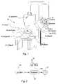
- FIG. 2is a schematic diagram illustrating various components of one of the subassemblies of FIG. 1 ;
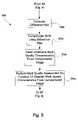
- FIG. 3is a flowchart illustrating at least one method that may be performed by the processor of FIG. 2 to identify mark quality and provide feedback;
- FIG. 4is a flowchart illustrating a subprocess that may be substituted for a portion of the process illustrated in FIG. 3 ;
- FIG. 5is a flowchart illustrating a subprocess that may be substituted for one of the process blocks of FIG. 4 ;
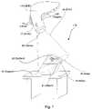
- FIG. 6is a schematic similar to FIG. 1 , albeit illustrating a second system configuration where a handheld reader as opposed to a stationary camera is employed to obtain an image of a mark;
- FIG. 7is similar to FIG. 6 , albeit showing the handheld reader in a second juxtaposition relative to a mark;
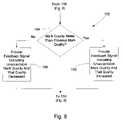
- FIG. 8is a flowchart illustrating a subprocess that may be substituted for a portion of the process of FIG. 3 where a handheld reader is used instead of a stationary camera to obtain an image of a mark;
- FIG. 9is a flowchart illustrating a subprocess that may be substituted for a portion of the process of FIG. 8 for providing more instructive feedback to a handheld reader user regarding quality of imaged marks to aid a user in movement of the handheld reader to a proper location for obtaining a suitable mark image for verification purposes;
- FIG. 10is a schematic similar to FIG. 6 , albeit showing a hand held reader with a distance extension member.
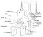
- FIG. 1one inventive embodiment will be described in a context of an exemplary marking and verification station 10 that includes, among other components, a marker or marking subassembly or machine 12 , a camera subassembly or camera 14 , a marked item support stand 16 and a marker/camera support stand 18 .
- support stand 16supports an item 21 to be marked on a top surface and, generally, so that a first surface 20 of item 21 on which a mark is to be applied is within a first area or space 22 .
- stand 16may take other forms including a position of a transfer line.
- Each of the marker 12 and camera 14are supported by stand 18 adjacent stand 16 and, more specifically, adjacent first area or space 22 .
- Marker 12is arranged with respect to first space 22 such that marker 12 can apply a two dimensional DataMatrix or other type of two dimensional mark 19 to surface 20 .
- marker 12may move vertically upward and downward at station 10 to apply marks 19 and to move out of the way so that items (e.g., 21 ) can be moved from station 10 to other locations without interference from marker 12 .
- camera 14includes optics 26 that focus a field of view 24 along a trajectory such that at least a portion of the field of view 24 forms an obtuse angle with the first surface 20 on which the two dimensional mark 19 is placed when item 21 is supported at station 10 .
- the entire first surface 20is within the field of view 24 of camera 14 . In other embodiments, it may be that just the portion of first surface 20 on which the mark 19 is applied is within the field of view of camera 14 .
- marker 12applies a two dimensional DataMatrix or other type of two dimensional mark 19 to first surface 20 .
- camera 14obtains an image of the mark 19 and the image is processed to verify that the mark is of sufficient quality to be used by mark readers subsequently.
- camera 14is linked to a processor 50 which may either be part of camera 14 , locally linked to camera 14 or may be remotely linked (e.g., via a local area network, a wide area network, the Internet, etc.).
- Processor 50is linked to one or more visual output devices 15 and/or one or more audio output devices 17 to provide feedback to a system user indicating the results of the verification process (e.g., whether or not the quality of the imaged mark meets or exceeds a baseline quality assessment value.
- visual feedback devicesmay include lights or light emitting diodes) 15 and the audio feedback device may include a small speaker or beeper device 17 .
- one of the visual devices 15may be illuminated when mark quality is at least equal to the baseline quality value while another of the LEDs 15 may be illuminated when mark quality is below the baseline quality value.
- different LED colorsmay be used to indicate whether or not the mark quality passes the baseline value test (e.g., a green LED may indicate high mark quality while a red LED indicates a mark that failed the quality test).
- known characteristics of the type of symbole.g., DataMatrix
- processor 50via a system interface (not illustrated, e.g. a computer).
- the known symbol characteristicsmay include, among others, a symbol affine grid, a symbol size, geometric features (e.g., boundary shape) of a symbol type, etc.
- a baseline quality valueis set.
- the baseline quality valuewill, in general, be some percentage assessment of a nominal value corresponding to a minimal resemblance required between an applied mark and what the mark would look like if it were an ideal mark.
- the baseline quality valuemay have a value of 80.
- a baseline value of 80would correspond to lesser resemblance than a baseline value of 90
- a baseline value of 90would correspond to lesser resemblance in a baseline value of 95, and so on.
- the algorithms used to identify quality valuesare a matter of designer choice but may take into account, in addition to other mark characteristics, symbol contrast, axial nonuniformity, grid nonuniformity, print growth, extreme reflection, angle of distortion, dot diameter, dot ovality, dot position, cell separability, symbol separability, finder pattern conformity, finder pattern conformity dot, image sharpness and background uniformity.
- Each factormay be equally weighted or, in at least some cases, factors may be differently weighted.
- a two dimensional markis applied to first surface 19 of component 21 at first station 10 via marker 12 .
- camera 14obtains an image of the two dimensional mark at first station 10 .
- processor 50attempts to decode the image to obtain an applied mark information subset.
- decodingcomprises actually reading out the information that is coded by the mark 19 to provide a first information subset.
- processor 50determines whether or not the two dimensional mark has been successfully decoded. Where the mark has not been successfully decoded control passes to block 84 where processor 50 provides at least one of an audible signal and a visual feedback signal indicating that the mark has not been successfully decoded. For instance, to indicate failure to decode, a red LED 15 (see FIGS. 1 and 2 ) may be illuminated. After block 84 , control passes back up to block 66 where item 21 is removed from station 10 and another item to be marked is moved to station for marking and verification. In at least some cases, after one or more mark verification processes result in failed mark verifications, a system operator may adjust marker 12 settings in a manner intended to increase mark quality.
- processor 50refines the corner locations of the mark 19 .
- processor 50estimates the distortion amount of the mark from the refined corner locations of the mark identified in block 74 . More specifically, for instance, if it is known that the two dimensional mark 19 has a square outer border or boundary, distortion may be estimated by comparing the actual mark boundary to a square shape.
- processor 50determines whether or not the mark distortion is less than or greater than a tolerable distortion level.
- processor 50may provide the feedback signal by illuminating one of the LEDs 50 or, alternatively, by generating a sound via speaker 17 .
- processor 50compares the applied mark quality value to the baseline quality value and, where the applied mark quality value is greater than the baseline value a feedback signal is provided at block 85 and where the applied mark quality value is below the baseline a quality failure signal is generated at block 83 .
- block 85the process ends.
- processor 50computes a synthetic ideal symbol model from the decoded data and the known symbol characteristics. To this end, processor 50 uses the mark information subset that was identified at process block 70 in FIG. 3 and the known symbol characteristics that were provided at process block 62 in FIG. 3 and generates an ideal synthetic symbol or mark model for the specific symbol or mark 19 that was applied to surface 20 and that was imaged via camera 14 .
- processor 50precisely locates the actual mark in the image that corresponds to the synthetic model.
- processor 50compares the actual mark image to the ideal synthetic symbol model to generate a deformation map.
- the deformation mapwould indicate how the rhombus could be stretched and compressed to result in a square.
- processor 50uses the deformation map to unwarp the original mark from the image. (e.g., in the previous example, by stretching and compressing the rhombus into a square).
- processor 50gleans additional mark quality characteristics from the unwarped image, and at block 96 processor 50 performs a mark quality assessment as a function of gleaned marked quality characteristics from the unwarped image.
- the mark qualityis again assessed and is compared to the baseline quality value as set at block 64 in FIG. 3 .
- decision block 98where mark quality is at an acceptable level, control passes back to block 85 in FIG. 3 where a feedback signal is provided that indicates that mark quality is at least at the baseline after which control again passes back up to block 68 .
- the subprocess 84 in FIG. 4can compensate for at least some degree of lens/optical distortion, perspective distortion and nonlinearities of the surface to which the mark 19 is applied (e.g., the surface 20 (see again FIG. 1 ) may be cylindrical, may be formed by a flexible sheet, etc.).
- irregularities in a mark image other than geometric deformationsmay be compensated for prior to completing a mark quality assessment.
- other image irregularitiesmay include non-uniform lighting of a mark that shows up in the obtained image, background texture of the surface (see 20 in FIG. 1 ) to which a mark is applied, etc.
- the degrees of the other irregularitiesmay be identified and compared to tolerable levels and when intolerable levels are identified, control may pass to the subprocess 84 of FIG. 4 .
- the subprocess in FIG. 4would be modified to compensate for the other irregularity.
- the subprocess 104 of FIG. 5may be substituted for a portion of the FIG. 4 subprocess 84 .
- FIG. 4after the mark is located in the image at block 88 , control passes to block 90 a in FIG. 5 where a difference map is computed that represents the perceived lighting difference between the synthetic ideal mark model (see block 86 ) and the imaged mark.
- the difference mapis used to compensate the imaged mark thereby generating a compensated image.
- a mark quality characteristicsare gleaned from the compensated image and at block 96 a an applied mark quality value is generated after which control passes back to block 98 in FIG. 4 .
- irregularity compensating processesmay be performed on an imaged mark prior to assessing mark quality. For instance, after decoding is successful at block 72 in FIG. 3 , geometric distortions may be compensated first after which the effects of lighting non-uniformity are compensated second, after which the effects of background surface texture are compensated, and so on. In another contemplated case, a single complex compensation algorithm may compensate for two or more irregularities (e.g., geometric distortion and lighting non-uniformity) simultaneously. Moreover, while FIG. 3 and the discussion above generally teach that irregularities are compensated only when they exceed tolerable levels (see block 78 ), in at least some embodiments irregularities may be compensated all the time irrespective of the degree of irregularity level. In this case, in FIG. 3 , control would pass directly from block 72 to block 86 in FIG. 4 where the synthetic ideal mark model is computed.
- FIG. 6a second embodiment consistent with at least some aspects of the present invention is illustrated that is used at a station 130 .
- components that are similar to the components described above with respect to FIG. 1are not described in detail. Instead, in the interest of simplifying this explanation, components that are similar to or identical to components described above with respect to FIG. 1 are labeled using the same numerals.
- numeral 16is used in each of FIGS. 1 and 6 to identify an item support table or structure
- numeral 24is used to label a camera field of view, etc.
- station 130does not include a marker or marker machine akin to marker 12 in FIG. 1 . While no marker is shown, in some embodiments a marker could be provided at station 130 .
- a handheld reader or camera device 114is included for use at station 130 for obtaining images that include images of marks (e.g., see 19 in FIG. 6 ).
- the handheld device 114includes optics 26 for focusing the field of view 24 of the reader, a trigger 126 that, when activated, causes the reader 114 to obtain an image, visual feedback devices such as, for instance, LEDs 15 , and an audio output device, in the illustrated embodiment, including a speaker 17 .
- reader 114would include a processor 50 linked to each of a camera and the output devices 15 and 17 .
- Reader 114may be feathered via a power and data card or may be wireless.
- device 114is portable and can be moved about station 130 , device 114 is not stationary and therefore the field of view 24 and its relation to a mark 19 can be and typically is altered during use. Because the orientation of device 114 changes with respect to marks being imaged, the amount of distortion associated with images obtained from different angles with respect to the mark surface 20 should vary. Thus, for instance, while a certain amount of distortion in the image of mark 19 will occur when handheld reader 114 is used to obtain an image from the angle shown in FIG. 6 , another amount of distortion will result when reader 114 is oriented as shown in FIG. 7 when an image of mark 19 is obtained.
- a slightly different processis performed to verify mark quality wherein, in at least some cases, a handheld reader user can be prompted to change the position of the reader 114 with respect to a mark when mark quality does not exceed a baseline quality value or when decoding fails.
- FIG. 8a subprocess 140 that may be substituted for a portion of the process shown in FIG. 3 is illustrated.
- the process steps 62 and 64are performed to provide known symbol characteristics and a baseline quality value to the processor 50 (see again FIG. 2 ) that is associated with handheld reader 114 .
- the two dimensional mark at block 66is applied either at station 130 or may have previously been applied at some other station or indeed at another facility.
- controlpasses to block 141 in FIG. 8 .
- a handheld reader useraligns the handheld reader at a first angle as shown in FIG.
- processor 50estimates the amount of distortion in the imaged mark (or the amount of some other irregularity of interest).
- processor 50determines if the distortion amount is at an acceptable level. Where distortion is below a tolerable level, a feedback signal is provided at block 158 .
- metricsare read from the imaged mark and an applied mark quality value is calculated which is compared to a baseline at block 161 .
- Appropriate feedback signalsare provided at blocks 158 or 160 . Where the feedback signal indicates a low quality mark, at block 150 the user is prompted to reposition the reader 114 to obtain another mark image. After block 160 the process ends.
- processor 50may use the feedback devices 15 and/or 17 to provide even more informative clues to a handheld reader user as to whether or not mark quality is increasing or decreasing as the reader is moved about with respect to a mark.
- a reader usermay depress trigger 126 and keep the trigger in the activated position thereby causing reader 114 to continually and quickly obtain new images whenever mark quality falls below the baseline value.
- the output signalscan be modified to indicate whether or not the quality is increasing or decreasing to aid the user in “hunting” for an appropriate juxtaposition between the reader and mark in which the mark is appropriately presented.
- the duration of beeps generated via speaker 17may be increased or the periods between beeps may be shortened almost like a Geiger counter to indicate an increase or decrease in quality.
- more LEDs 15may be energized until, when all of the LEDs 15 are energized, an image of a mark is obtained with a mark that has a quality level that exceeds the baseline level.
- FIG. 9an exemplary method subprocess 162 that may be substituted for process block 158 in FIG. 8 is illustrated.
- controlmay pass to block 164 in FIG. 9 where processor 50 determines whether or not the mark quality is better than the previous mark quality associated with the previously obtained image.
- a feedback signalis provided that indicates unacceptable mark quality and that the quality is decreasing.
- controlpasses to block 168 where the feedback signal indicates that the mark quality signal is unacceptable but that the quality is increasing
- FIG. 10another exemplary embodiment of a hand held reader 214 is shown for reading a mark 19 on a first surface 20 of an object 21 .
- the reader 214is different than the readers described above in that reader 214 includes a range finder or range extension 216 that extends from a front end thereof.
- Range extensin 216is a rigid member that extends along a trajectory that is substantially parallel to the central trajectory (not labeled) along which the reader field of view 24 is directed.
- a reader userpositions reader 214 so that a distal end 218 of extension contacts first surface 20 adjacent a mark 19 to be read prior to activating the reader 214 .
- the length of extensin 216is designed so that an optimal imaging distance occurs between the reader 214 and surface 20 when distal end 218 contacts surface 20 .
- extension 216contains at least one imaging variable in at least some embodiments.
- extension 216is shown as rigid and integrally formed with reader 214 , in some cases extension 216 may be flexible, may be telescoping like a radio antenna, may fold into a storage position, etc. In some cases extensin 216 may be removable. For instance, extensin 216 may include an external thread at the proximal end or may otherwise attach at the proximal end (e.g., via a collar or the like that fits over the lateral portion of optics 26 ).
Landscapes
- Physics & Mathematics (AREA)
- General Physics & Mathematics (AREA)
- Engineering & Computer Science (AREA)
- Theoretical Computer Science (AREA)
- Image Processing (AREA)
- Studio Devices (AREA)
Abstract
Description
Claims (26)
Priority Applications (3)
| Application Number | Priority Date | Filing Date | Title |
|---|---|---|---|
| US11/427,420US8108176B2 (en) | 2006-06-29 | 2006-06-29 | Method and apparatus for verifying two dimensional mark quality |
| US11/743,193US8027802B1 (en) | 2006-06-29 | 2007-05-02 | Method and apparatus for verifying two dimensional mark quality |
| US13/270,370US9465962B2 (en) | 2006-06-29 | 2011-10-11 | Method and apparatus for verifying two dimensional mark quality |
Applications Claiming Priority (1)
| Application Number | Priority Date | Filing Date | Title |
|---|---|---|---|
| US11/427,420US8108176B2 (en) | 2006-06-29 | 2006-06-29 | Method and apparatus for verifying two dimensional mark quality |
Related Child Applications (2)
| Application Number | Title | Priority Date | Filing Date |
|---|---|---|---|
| US11/743,193ContinuationUS8027802B1 (en) | 2006-06-29 | 2007-05-02 | Method and apparatus for verifying two dimensional mark quality |
| US13/270,370DivisionUS9465962B2 (en) | 2006-06-29 | 2011-10-11 | Method and apparatus for verifying two dimensional mark quality |
Publications (2)
| Publication Number | Publication Date |
|---|---|
| US20080004822A1 US20080004822A1 (en) | 2008-01-03 |
| US8108176B2true US8108176B2 (en) | 2012-01-31 |
Family
ID=38877748
Family Applications (3)
| Application Number | Title | Priority Date | Filing Date |
|---|---|---|---|
| US11/427,420Expired - Fee RelatedUS8108176B2 (en) | 2006-06-29 | 2006-06-29 | Method and apparatus for verifying two dimensional mark quality |
| US11/743,193Expired - Fee RelatedUS8027802B1 (en) | 2006-06-29 | 2007-05-02 | Method and apparatus for verifying two dimensional mark quality |
| US13/270,370Expired - Fee RelatedUS9465962B2 (en) | 2006-06-29 | 2011-10-11 | Method and apparatus for verifying two dimensional mark quality |
Family Applications After (2)
| Application Number | Title | Priority Date | Filing Date |
|---|---|---|---|
| US11/743,193Expired - Fee RelatedUS8027802B1 (en) | 2006-06-29 | 2007-05-02 | Method and apparatus for verifying two dimensional mark quality |
| US13/270,370Expired - Fee RelatedUS9465962B2 (en) | 2006-06-29 | 2011-10-11 | Method and apparatus for verifying two dimensional mark quality |
Country Status (1)
| Country | Link |
|---|---|
| US (3) | US8108176B2 (en) |
Cited By (9)
| Publication number | Priority date | Publication date | Assignee | Title |
|---|---|---|---|---|
| US20050275831A1 (en)* | 2004-06-09 | 2005-12-15 | Silver William M | Method and apparatus for visual detection and inspection of objects |
| US20050276460A1 (en)* | 2004-06-09 | 2005-12-15 | Silver William M | Method and apparatus for automatic visual event detection |
| US20050276461A1 (en)* | 2004-06-09 | 2005-12-15 | Silver William M | Method and apparatus for automatic visual detection, recording, and retrieval of events |
| US20120207395A1 (en)* | 2011-02-09 | 2012-08-16 | Testo Ag | Measuring device set and method for documenting a measurement |
| US8782553B2 (en) | 2004-06-09 | 2014-07-15 | Cognex Corporation | Human-machine-interface and method for manipulating data in a machine vision system |
| US9183443B2 (en) | 2004-06-09 | 2015-11-10 | Cognex Technology And Investment Llc | Method and apparatus for configuring and testing a machine vision detector |
| US9292187B2 (en) | 2004-11-12 | 2016-03-22 | Cognex Corporation | System, method and graphical user interface for displaying and controlling vision system operating parameters |
| US9651499B2 (en) | 2011-12-20 | 2017-05-16 | Cognex Corporation | Configurable image trigger for a vision system and method for using the same |
| US10740582B1 (en) | 2019-01-22 | 2020-08-11 | Datalogic IP Tech, S.r.l. | Generic shape quality verification process for a mark and read system |
Families Citing this family (17)
| Publication number | Priority date | Publication date | Assignee | Title |
|---|---|---|---|---|
| US7963448B2 (en) | 2004-12-22 | 2011-06-21 | Cognex Technology And Investment Corporation | Hand held machine vision method and apparatus |
| US9552506B1 (en) | 2004-12-23 | 2017-01-24 | Cognex Technology And Investment Llc | Method and apparatus for industrial identification mark verification |
| US8108176B2 (en) | 2006-06-29 | 2012-01-31 | Cognex Corporation | Method and apparatus for verifying two dimensional mark quality |
| US7984854B2 (en)* | 2006-07-17 | 2011-07-26 | Cognex Corporation | Method and apparatus for multiplexed symbol decoding |
| US8169478B2 (en)* | 2006-12-14 | 2012-05-01 | Cognex Corporation | Method and apparatus for calibrating a mark verifier |
| US9734376B2 (en) | 2007-11-13 | 2017-08-15 | Cognex Corporation | System and method for reading patterns using multiple image frames |
| US20110044510A1 (en)* | 2008-05-21 | 2011-02-24 | Ferag Ag | Optical control method for further print processing |
| US8740076B2 (en) | 2012-07-11 | 2014-06-03 | Linksmart Technologies Pvt. Ltd. | Label for enabling verification of an object |
| JP5708357B2 (en)* | 2011-08-09 | 2015-04-30 | 株式会社デンソーウェーブ | Information code verifier |
| RS57033B1 (en)* | 2012-03-01 | 2018-05-31 | Sys Tech Solutions Inc | Unique identification information from marked features |
| US8873892B2 (en) | 2012-08-21 | 2014-10-28 | Cognex Corporation | Trainable handheld optical character recognition systems and methods |
| US10068153B2 (en) | 2012-08-21 | 2018-09-04 | Cognex Corporation | Trainable handheld optical character recognition systems and methods |
| US8998090B1 (en)* | 2013-03-15 | 2015-04-07 | Cognex Corporation | Standoff for optical imaging system |
| EP3304413A4 (en)* | 2015-01-25 | 2019-02-20 | YTA Holdings, LLC | Method and system for determining quality of markings applied to food products |
| USD848428S1 (en)* | 2017-11-08 | 2019-05-14 | Lee Seng Fook | Hand held 3D scanning device |
| USD848429S1 (en)* | 2017-11-08 | 2019-05-14 | Lee Seng Fook | Hand held 3D scanning device with feedback system |
| US10740581B2 (en)* | 2018-12-03 | 2020-08-11 | Zebra Technologies Corporation | Dual mode reader and method of reading DPM codes therewith |
Citations (161)
| Publication number | Priority date | Publication date | Assignee | Title |
|---|---|---|---|---|
| US3868634A (en) | 1972-11-03 | 1975-02-25 | Scanner | Reading of contrasting data by means of continuously attempting to decode read signals |
| US3890597A (en) | 1973-09-17 | 1975-06-17 | Taplin Business Machines | Bar geometry verification system for bar-coded characters |
| US4282425A (en) | 1979-07-25 | 1981-08-04 | Norand Corporation | Instant portable bar code reader |
| US4308455A (en) | 1980-06-26 | 1981-12-29 | E. I. Du Pont De Nemours And Company | Method for decoding bar-coded labels |
| US4421978A (en) | 1981-08-20 | 1983-12-20 | International Business Machines Corporation | Decoding method for multicharacter labels |
| US4782220A (en) | 1986-09-29 | 1988-11-01 | Mars, Incorporated | Method and apparatus for bar code data autodiscrimination |
| US4866784A (en) | 1987-12-02 | 1989-09-12 | Eastman Kodak Company | Skew detector for digital image processing system |
| US4894523A (en) | 1981-12-28 | 1990-01-16 | Norand Corporation | Instant portable bar code reader |
| US4948955A (en) | 1988-12-22 | 1990-08-14 | The Boeing Company | Barcode location determination |
| US4973829A (en) | 1988-11-22 | 1990-11-27 | Eastman Kodak Company | Bar code reading method |
| US5028772A (en) | 1988-08-26 | 1991-07-02 | Accu-Sort Systems, Inc. | Scanner to combine partial fragments of a complete code |
| US5120940A (en) | 1990-08-10 | 1992-06-09 | The Boeing Company | Detection of barcodes in binary images with arbitrary orientation |
| US5124538A (en) | 1988-08-26 | 1992-06-23 | Accu-Sort Systems, Inc. | Scanner |
| US5124537A (en) | 1990-10-29 | 1992-06-23 | Omniplanar, Inc. | Omnidirectional bar code reader using virtual scan of video raster scan memory |
| US5155343A (en) | 1990-03-28 | 1992-10-13 | Chandler Donald G | Omnidirectional bar code reader with method and apparatus for detecting and scanning a bar code symbol |
| US5163104A (en) | 1988-02-24 | 1992-11-10 | Transtechnology Corporation | Digital image processing technique including improved gray scale compression |
| US5166830A (en) | 1989-09-29 | 1992-11-24 | Hoya Corporation | Aspherical lens system for a bar code sensor |
| US5187355A (en) | 1981-12-28 | 1993-02-16 | Norand Corporation | Instant portable bar code reader |
| US5187356A (en) | 1981-12-28 | 1993-02-16 | Norand Corporation | Instant portable bar code reader |
| US5192856A (en) | 1990-11-19 | 1993-03-09 | An Con Genetics, Inc. | Auto focusing bar code reader |
| US5262623A (en) | 1991-09-04 | 1993-11-16 | Omniplanar, Inc. | Method and apparatus for distinguishing a preferred bar code or the like |
| US5262626A (en) | 1989-12-06 | 1993-11-16 | Symbol Technologies, Inc. | Decoding bar codes from multiple scans using element replacement |
| US5262652A (en) | 1991-05-14 | 1993-11-16 | Applied Materials, Inc. | Ion implantation apparatus having increased source lifetime |
| US5276316A (en) | 1990-05-02 | 1994-01-04 | Ncr Corporation | Method for reconstructing complete bar code signals from partial bar code scans |
| US5276315A (en) | 1992-05-14 | 1994-01-04 | United Parcel Service Of America, Inc. | Method and apparatus for processing low resolution images of degraded bar code symbols |
| US5278397A (en) | 1991-07-25 | 1994-01-11 | Symbol Technologies, Inc. | Multi-resolution bar code reader |
| US5286960A (en) | 1991-11-04 | 1994-02-15 | Welch Allyn, Inc. | Method of programmable digitization and bar code scanning apparatus employing same |
| US5291008A (en) | 1992-01-10 | 1994-03-01 | Welch Allyn, Inc. | Optical assembly and apparatus employing same using an aspherical lens and an aperture stop |
| US5296690A (en) | 1991-03-28 | 1994-03-22 | Omniplanar, Inc. | System for locating and determining the orientation of bar codes in a two-dimensional image |
| US5304786A (en) | 1990-01-05 | 1994-04-19 | Symbol Technologies, Inc. | High density two-dimensional bar code symbol |
| US5332892A (en) | 1991-07-25 | 1994-07-26 | Symbol Technologies, Inc. | Optical systems for bar code scanners |
| US5378883A (en) | 1991-07-19 | 1995-01-03 | Omniplanar Inc. | Omnidirectional wide range hand held bar code reader |
| US5412197A (en) | 1993-01-29 | 1995-05-02 | United Parcel Service Of America, Inc. | Method and apparatus for decoding bar code symbols using gradient signals |
| US5418862A (en) | 1992-08-10 | 1995-05-23 | United Parcel Service Of America | Method and apparatus for detecting artifact corners in two-dimensional images |
| US5420409A (en) | 1993-10-18 | 1995-05-30 | Welch Allyn, Inc. | Bar code scanner providing aural feedback |
| US5446271A (en) | 1993-08-06 | 1995-08-29 | Spectra-Physics Scanning Systems, Inc. | Omnidirectional scanning method and apparatus |
| US5455414A (en) | 1994-09-15 | 1995-10-03 | Metanetics Corporation | Simplified bar code decoding with dynamically loadable data character sets |
| US5461417A (en) | 1993-02-16 | 1995-10-24 | Northeast Robotics, Inc. | Continuous diffuse illumination method and apparatus |
| US5463214A (en) | 1994-03-04 | 1995-10-31 | Welch Allyn, Inc. | Apparatus for optimizing throughput in decoded-output scanners and method of using same |
| US5478999A (en) | 1992-08-10 | 1995-12-26 | United Parcel Service Of America, Inc. | Method and apparatus for decoding bar code symbols along search steps |
| US5481098A (en) | 1993-11-09 | 1996-01-02 | Spectra-Physics Scanning Systems, Inc. | Method and apparatus for reading multiple bar code formats |
| US5483051A (en) | 1993-11-04 | 1996-01-09 | Datalogic S.P.A. | Laser bar code reader measuring phase of the pulse laser to determine the distance |
| US5487115A (en) | 1992-05-14 | 1996-01-23 | United Parcel Service | Method and apparatus for determining the fine angular orientation of bar code symbols in two-dimensional CCD images |
| US5486689A (en) | 1993-01-22 | 1996-01-23 | Intermec Corporation | Method and apparatus for decoding unresolved multi-width bar code symbology profiles |
| US5507527A (en) | 1993-12-30 | 1996-04-16 | Tomioka; Makoto | Two dimensional code for processing data |
| US5514858A (en) | 1995-02-10 | 1996-05-07 | Intermec Corporation | Method and apparatus for decoding unresolved complex multi-width bar code symbology profiles |
| US5523552A (en) | 1994-10-19 | 1996-06-04 | Symbol Technologies, Inc. | Method and apparatus to scan randomly oriented two-dimensional bar code symbols |
| US5539191A (en) | 1995-06-22 | 1996-07-23 | Intermec Corporation | Method and apparatus for decoding unresolved bar code profiles using edge finding circuitry |
| US5550366A (en) | 1994-06-20 | 1996-08-27 | Roustaei; Alexander | Optical scanner with automatic activation |
| US5557091A (en) | 1994-04-15 | 1996-09-17 | Krummel; Larry | Method and system for bar code image processing |
| US5591956A (en) | 1995-05-15 | 1997-01-07 | Welch Allyn, Inc. | Two dimensional data encoding structure and symbology for use with optical readers |
| US5612524A (en) | 1987-11-25 | 1997-03-18 | Veritec Inc. | Identification symbol system and method with orientation mechanism |
| US5646391A (en) | 1995-05-11 | 1997-07-08 | Psc, Inc. | Optical assembly for controlling beam size in bar code scanners |
| US5657402A (en) | 1991-11-01 | 1997-08-12 | Massachusetts Institute Of Technology | Method of creating a high resolution still image using a plurality of images and apparatus for practice of the method |
| US5675137A (en) | 1986-04-18 | 1997-10-07 | Cias, Inc. | Bar code decoding using moving averages to break the (n,k) code barrier for UPC, EAN Code 128 and others |
| US5682030A (en) | 1993-02-02 | 1997-10-28 | Label Vision Systems Inc | Method and apparatus for decoding bar code data from a video signal and application thereof |
| US5691597A (en) | 1995-01-27 | 1997-11-25 | Kabushiki Kaisha Toshiba | Color cathode-ray tube and method for manufacturing the same |
| US5723853A (en) | 1995-01-10 | 1998-03-03 | Welch Allyn, Inc. | Bar code reader |
| US5739518A (en) | 1995-05-17 | 1998-04-14 | Metanetics Corporation | Autodiscrimination for dataform decoding and standardized recording |
| US5742037A (en) | 1996-03-07 | 1998-04-21 | Cognex Corp. | Method and apparatus for high speed identification of objects having an identifying feature |
| US5744790A (en) | 1996-01-25 | 1998-04-28 | Symbol Technologies, Inc. | Split optics focusing apparatus for CCD-based bar code scanner |
| US5756981A (en) | 1992-02-27 | 1998-05-26 | Symbol Technologies, Inc. | Optical scanner for reading and decoding one- and-two-dimensional symbologies at variable depths of field including memory efficient high speed image processing means and high accuracy image analysis means |
| US5767497A (en) | 1996-12-04 | 1998-06-16 | United Parcel Service Of America, Inc. | Method and apparatus for decoding bar code symbols using ratio analysis of module size |
| US5767498A (en) | 1996-09-17 | 1998-06-16 | Ncr Corporation | Bar code error scanner |
| US5777309A (en) | 1995-10-30 | 1998-07-07 | Intermec Corporation | Method and apparatus for locating and decoding machine-readable symbols |
| US5786586A (en) | 1995-01-17 | 1998-07-28 | Welch Allyn, Inc. | Hand-held optical reader having a detachable lens-guide assembly |
| US5814827A (en) | 1995-05-19 | 1998-09-29 | Symbol Technologies, Inc. | Optical scanner with extended depth of focus |
| US5821520A (en) | 1995-04-28 | 1998-10-13 | Symbol Technologies, Inc. | Bar code scanning system with the pre-decoding signal processing and method for bar code candidate selection for decoding |
| US5825006A (en) | 1994-03-04 | 1998-10-20 | Welch Allyn, Inc. | Optical reader having improved autodiscrimination features |
| US5852288A (en) | 1994-09-19 | 1998-12-22 | Sumitomo Electric Industries, Ltd. | Bar code scanning apparatus |
| US5872354A (en) | 1989-01-31 | 1999-02-16 | Norand Corporation | Hand-held data capture system with interchangable modules including autofocusing data file reader using the slope of the image signal to determine focus |
| US5877486A (en) | 1996-10-11 | 1999-03-02 | Intermec Ip Corp. | Method and apparatus for enhancing resolution of reflectance signals produced from machine-readable symbols |
| US5880451A (en) | 1997-04-24 | 1999-03-09 | United Parcel Service Of America, Inc. | System and method for OCR assisted bar code decoding |
| US5902988A (en) | 1992-03-12 | 1999-05-11 | Norand Corporation | Reader for decoding two-dimensional optically readable information |
| US5914476A (en) | 1997-11-04 | 1999-06-22 | Welch Allyn, Inc. | Optical reader configured to accurately and rapidly read multiple symbols |
| US5920060A (en) | 1995-09-21 | 1999-07-06 | Symbol Technologies, Inc. | Bar code scanner with simplified auto-focus capablilty |
| US5929418A (en) | 1994-03-04 | 1999-07-27 | Welch Allyn, Inc. | Optical reader having improved menuing features |
| US5932862A (en) | 1994-03-04 | 1999-08-03 | Welch Allyn, Inc. | Optical reader having improved scanning-decoding features |
| US5936224A (en) | 1996-12-11 | 1999-08-10 | Intermec Ip Corporation | Method and apparatus for reading machine-readable symbols by employing a combination of multiple operators and/or processors |
| US5949052A (en) | 1997-10-17 | 1999-09-07 | Welch Allyn, Inc. | Object sensor system for stationary position optical reader |
| EP0571892B1 (en) | 1992-05-26 | 1999-10-13 | United Parcel Service Of America, Inc. | Multiple code camera system |
| US6000612A (en) | 1997-10-10 | 1999-12-14 | Metanetics Corporation | Portable data collection device having optical character recognition |
| US6006990A (en) | 1995-09-12 | 1999-12-28 | Telxon Corporation | Dataform reader utilizing hand jittering compensation method |
| US6021946A (en) | 1997-03-14 | 2000-02-08 | Sick Ag | Self-focusing bar code reader and optical receiving system |
| US6053407A (en) | 1995-05-31 | 2000-04-25 | Metanetics Corporation | Maxicode data extraction using spatial domain features |
| US6056198A (en) | 1997-08-07 | 2000-05-02 | Psc Scanning, Inc. | Optical scanning system and method including a collection system for range enhancement |
| US6075905A (en) | 1996-07-17 | 2000-06-13 | Sarnoff Corporation | Method and apparatus for mosaic image construction |
| US6075883A (en) | 1996-11-12 | 2000-06-13 | Robotic Vision Systems, Inc. | Method and system for imaging an object or pattern |
| US6078251A (en) | 1996-03-27 | 2000-06-20 | Intermec Ip Corporation | Integrated multi-meter and wireless communication link |
| US6082619A (en) | 1998-12-16 | 2000-07-04 | Matsushita Electric Industrial Co., Ltd. | Method for locating and reading a two-dimensional barcode |
| US6088482A (en) | 1998-10-22 | 2000-07-11 | Symbol Technologies, Inc. | Techniques for reading two dimensional code, including maxicode |
| US6095422A (en) | 1998-01-14 | 2000-08-01 | Intermec Ip Corp. | Method and apparatus of autodiscriminating in symbol reader employing prioritized and updated table of symbologies |
| DE10012715A1 (en) | 1999-03-19 | 2000-09-21 | Joerg Kuechen | Scanner positioning to coded surface, to read bar codes has measurement unit to correct distance and measurement unit to correct orientation |
| US6123261A (en) | 1997-05-05 | 2000-09-26 | Roustaei; Alexander R. | Optical scanner and image reader for reading images and decoding optical information including one and two dimensional symbologies at variable depth of field |
| US6152371A (en) | 1998-08-12 | 2000-11-28 | Welch Allyn, Inc. | Method and apparatus for decoding bar code symbols |
| US6158661A (en) | 1981-12-28 | 2000-12-12 | Intermec Ip Corp. | Instant portable bar code reader |
| US6161760A (en) | 1998-09-14 | 2000-12-19 | Welch Allyn Data Collection, Inc. | Multiple application multiterminal data collection network |
| US6176428B1 (en) | 1999-04-07 | 2001-01-23 | Symbol Technologies, Inc. | Techniques for reading postal code |
| US6189792B1 (en) | 1999-12-14 | 2001-02-20 | Ncr Corporation | System and methods for exemplar based bar code error detection and correction |
| US6209789B1 (en) | 1991-09-17 | 2001-04-03 | Metrologic Instruments, Inc. | Optical filtering system for a laser bar code scanner having narrow band-pass characteristics employing spatially separated filtering elements including a scanner window |
| US6234395B1 (en) | 1981-12-28 | 2001-05-22 | Intermec Ip Corp. | Instant portable bar code reader |
| US6250551B1 (en) | 1998-06-12 | 2001-06-26 | Symbol Technologies, Inc. | Autodiscrimination and line drawing techniques for code readers |
| US6289113B1 (en) | 1998-11-25 | 2001-09-11 | Iridian Technologies, Inc. | Handheld iris imaging apparatus and method |
| US6298176B2 (en) | 1997-10-17 | 2001-10-02 | Welch Allyn Data Collection, Inc. | Symbol-controlled image data reading system |
| US20010042065A1 (en) | 2000-04-28 | 2001-11-15 | Nec Corporation | Appearance inspection apparatus and appearance inspection method |
| US20010042789A1 (en) | 2000-05-17 | 2001-11-22 | Mark Krichever | Bioptics bar code reader |
| US6371373B1 (en) | 1999-05-25 | 2002-04-16 | Matsushita Electric Industrial Co., Ltd. | Method for reading a two-dimensional barcode |
| US20020044689A1 (en) | 1992-10-02 | 2002-04-18 | Alex Roustaei | Apparatus and method for global and local feature extraction from digital images |
| US6398113B1 (en) | 1999-12-23 | 2002-06-04 | Ncr Corporation | System and methods for collaborative bar code error detection and correction |
| US6408429B1 (en) | 1997-01-17 | 2002-06-18 | Cognex Corporation | Machine vision system for identifying and assessing features of an article |
| US6446868B1 (en) | 1998-11-23 | 2002-09-10 | Informatics, Inc. | Scanning system for decoding two-dimensional barcode symbologies with a one-dimensional general purpose scanner |
| US6454168B1 (en) | 1998-09-14 | 2002-09-24 | Psc Scanning, Inc. | Correlation and stitching techniques in a bar code scanning system |
| US20020171745A1 (en) | 2001-05-15 | 2002-11-21 | Welch Allyn Data Collection, Inc. | Multimode image capturing and decoding optical reader |
| US6490376B1 (en) | 1998-09-17 | 2002-12-03 | Metrologic Instruments, Inc. | Skew processing of raster scan images |
| US6491223B1 (en) | 1996-09-03 | 2002-12-10 | Hand Held Products, Inc. | Autodiscriminating optical reader |
| US20030006290A1 (en) | 2001-05-02 | 2003-01-09 | Hand Held Products, Inc. | Optical reader comprising soft key including permanent graphic indicia |
| US6505778B1 (en) | 1998-07-17 | 2003-01-14 | Psc Scanning, Inc. | Optical reader with selectable processing characteristics for reading data in multiple formats |
| US6512714B2 (en) | 2001-02-15 | 2003-01-28 | Hitachi, Ltd. | Semiconductor memory device equipped with dummy cells |
| US6513714B1 (en) | 1998-09-14 | 2003-02-04 | Psc Scanning, Inc. | Character reconstruction and element level processing in bar code scanning system |
| US6561427B2 (en) | 1998-09-14 | 2003-05-13 | Psc Scanning, Inc. | Decoding system and methods in a bar code scanning system |
| US20030117511A1 (en) | 2001-12-21 | 2003-06-26 | Eastman Kodak Company | Method and camera system for blurring portions of a verification image to show out of focus areas in a captured archival image |
| US20030121978A1 (en) | 2000-07-14 | 2003-07-03 | Rubin Kim T. | Compact matrix code and one-touch device and method for code reading |
| US6629642B1 (en) | 1996-08-02 | 2003-10-07 | Symbol Technologies, Inc. | Data system and method for accessing a computer network using a collection of bar code symbols |
| US6677852B1 (en) | 1999-09-22 | 2004-01-13 | Intermec Ip Corp. | System and method for automatically controlling or configuring a device, such as an RFID reader |
| US6681151B1 (en) | 2000-12-15 | 2004-01-20 | Cognex Technology And Investment Corporation | System and method for servoing robots based upon workpieces with fiducial marks using machine vision |
| US6728419B1 (en) | 2000-02-17 | 2004-04-27 | Xerox Corporation | Multi-tasking multi-threaded image processing system and method for image capture devices |
| US20040091255A1 (en) | 2002-11-11 | 2004-05-13 | Eastman Kodak Company | Camera flash circuit with adjustable flash illumination intensity |
| US6761316B2 (en) | 2001-03-27 | 2004-07-13 | Symbol Technologies, Inc. | Compact auto ID reader and radio frequency transceiver data collection module |
| EP0896290B1 (en) | 1997-08-06 | 2004-10-20 | Sick AG | Method and device for reading a barcode consisting of a predetermined number of coding elements |
| US6816063B2 (en) | 1999-01-29 | 2004-11-09 | Intermec Ip Corp | Radio frequency identification systems and methods for waking up data storage devices for wireless communication |
| US6913199B2 (en) | 2002-12-18 | 2005-07-05 | Symbol Technologies, Inc. | System and method for verifying optical character recognition of optical code reads |
| US6919793B2 (en) | 1994-09-09 | 2005-07-19 | Intermec Ip Corp. | Radio frequency identification system write broadcast capability |
| US20050194447A1 (en) | 2004-03-02 | 2005-09-08 | Duanfeng He | System and method for illuminating and reading optical codes imprinted or displayed on reflective surfaces |
| US20050263599A1 (en) | 2003-11-13 | 2005-12-01 | Metrologic Instruments, Inc. | Digital imaging-based bar code symbol reading system employing a multi-mode image-processing symbol reading subsystem that switches its modes of reading during a single bar code symbol reading cycle, and within each said mode of reading, automatically applies a different image-processing based bar code symbol reading methodology |
| US20050275897A1 (en)* | 2004-06-14 | 2005-12-15 | Xerox Corporation | Method for image segmentation to identify regions with constant foreground color |
| US20060022052A1 (en) | 2004-07-29 | 2006-02-02 | Mehul Patel | System and method for decoding optical codes read by an imager-based optical code reader |
| US20060027661A1 (en) | 2004-08-09 | 2006-02-09 | Kazukuni Hosoi | Method of decoding a symbol with a low contrast |
| US20060027657A1 (en) | 2004-08-04 | 2006-02-09 | Laurens Ninnink | Method and apparatus for high resolution decoding of encoded symbols |
| US20060050961A1 (en) | 2004-08-13 | 2006-03-09 | Mohanaraj Thiyagarajah | Method and system for locating and verifying a finder pattern in a two-dimensional machine-readable symbol |
| US7044378B2 (en) | 2002-12-18 | 2006-05-16 | Symbol Technologies, Inc. | System and method for imaging and decoding optical codes using at least two different imaging settings |
| US7061524B2 (en) | 2001-11-13 | 2006-06-13 | The Board Of Trustees Of The Leland Stanford Junior University | Motion/saturation detection system and method for synthesizing high dynamic range motion blur free images from multiple captures |
| US20060131418A1 (en) | 2004-12-22 | 2006-06-22 | Justin Testa | Hand held machine vision method and apparatus |
| US20060132787A1 (en)* | 2004-12-20 | 2006-06-22 | Xerox Corporation | Full width array mechanically tunable spectrophotometer |
| US7070099B2 (en) | 2004-09-30 | 2006-07-04 | Symbol Technologies, Inc. | Modular architecture for a data capture device |
| US7121467B2 (en) | 2004-05-21 | 2006-10-17 | Intermec Ip Corp. | Indicators of optimum positioning of a data collection device for reading data carriers, such as RFID tags and machine-readable symbols |
| US20060249581A1 (en) | 2005-05-03 | 2006-11-09 | Smith Larry J | Methods and systems for forming images of moving optical codes |
| US20060285135A1 (en)* | 2005-06-15 | 2006-12-21 | Xerox Corporation | System and method for dynamically generated uniform color objects |
| US7175090B2 (en) | 2004-08-30 | 2007-02-13 | Cognex Technology And Investment Corporation | Methods and apparatus for reading bar code identifications |
| US7181066B1 (en) | 2002-12-26 | 2007-02-20 | Cognex Technology And Investment Corporation | Method for locating bar codes and symbols in an image |
| US7219841B2 (en) | 2004-11-05 | 2007-05-22 | Hand Held Products, Inc. | Device and system for verifying quality of bar codes |
| US20080004822A1 (en) | 2006-06-29 | 2008-01-03 | Sateesha Nadabar | Method and Apparatus for Verifying Two Dimensional Mark Quality |
| US20080011855A1 (en) | 2006-07-17 | 2008-01-17 | Sateesha Nadabar | Method and Apparatus for Multiplexed Symbol Decoding |
| US20080019615A1 (en) | 2002-06-27 | 2008-01-24 | Schnee Michael D | Digital image acquisition system capable of compensating for changes in relative object velocity |
| US20080143838A1 (en) | 2006-12-14 | 2008-06-19 | Sateesha Nadabar | Method and apparatus for calibrating a mark verifier |
| WO2008118425A1 (en) | 2007-03-23 | 2008-10-02 | Ltt, Ltd | Method and apparatus for using a limited capacity portable data carrier |
| WO2008118419A1 (en) | 2007-03-23 | 2008-10-02 | Ltt, Ltd | Method and apparatus for reading a printed indicia with a limited field of view sensor |
| EP1469420B1 (en) | 2003-04-17 | 2009-03-04 | Anoto Group AB | Method, system and program for reconstructing a bar code |
| US20090090781A1 (en)* | 2005-12-20 | 2009-04-09 | Xiangyun Ye | Decoding distorted symbols |
| US20090121027A1 (en) | 2007-11-13 | 2009-05-14 | Cognex Corporation | System and method for reading patterns using multiple image frames |
| US7604174B2 (en) | 2003-10-24 | 2009-10-20 | Cognex Technology And Investment Corporation | Method and apparatus for providing omnidirectional lighting in a scanning device |
| EP1975849B1 (en) | 2007-03-27 | 2011-04-27 | Casio Computer Co., Ltd. | Bar-code reading apparatus and computer-readable medium |
Family Cites Families (38)
| Publication number | Priority date | Publication date | Assignee | Title |
|---|---|---|---|---|
| US4408344A (en) | 1981-04-09 | 1983-10-04 | Recognition Equipment Incorporated | OCR and Bar code reader using multi port matrix array |
| IT1150467B (en) | 1982-03-17 | 1986-12-10 | Pama Spa | PROCEDURE FOR THE FORMATION OF SOLES WITH HEEL AND SUB-HEEL, FOR MAXIMUM FEMALE SHOES WITH SUPPORTING BODY OR INCORPORATED ARMOR AND SHAPED AND ARMED SOLES OBTAINED WITH THAT PROCEDURE |
| US5053609A (en) | 1988-05-05 | 1991-10-01 | International Data Matrix, Inc. | Dynamically variable machine readable binary code and method for reading and producing thereof |
| US5198650A (en) | 1991-06-24 | 1993-03-30 | Ncr Corporation | Hands free/hand held bar code scanner |
| US5262625A (en) | 1991-11-15 | 1993-11-16 | Ncr Corporation | Multiple bar code decoding system and method |
| JP3238507B2 (en) | 1992-12-21 | 2001-12-17 | 旭光学工業株式会社 | Special symbol reader |
| US5304787A (en) | 1993-06-01 | 1994-04-19 | Metamedia Corporation | Locating 2-D bar codes |
| US5627358A (en) | 1994-06-20 | 1997-05-06 | Roustaei; Alexander | System and method for reading two-dimensional barcodes |
| US5811784A (en) | 1995-06-26 | 1998-09-22 | Telxon Corporation | Extended working range dataform reader |
| DE69502293T2 (en) | 1994-10-25 | 1998-11-26 | United Parcel Service Of America, Inc., Atlanta, Ga. | METHOD AND DEVICE FOR A PORTABLE CONTACTLESS IMAGE RECORDING DEVICE |
| US5780834A (en) | 1995-05-15 | 1998-07-14 | Welch Allyn, Inc. | Imaging and illumination optics assembly |
| US6021380A (en)* | 1996-07-09 | 2000-02-01 | Scanis, Inc. | Automatic semiconductor wafer sorter/prober with extended optical inspection |
| US5992744A (en) | 1997-02-18 | 1999-11-30 | Welch Allyn, Inc. | Optical reader having multiple scanning assemblies with simultaneously decoded outputs |
| US6141033A (en) | 1997-05-15 | 2000-10-31 | Cognex Corporation | Bandwidth reduction of multichannel images for machine vision |
| US6334060B1 (en) | 1997-10-28 | 2001-12-25 | Acumen, Inc. | Multi-channel or split-frequency, low frequency, telemetry circuit and method between transmitters and receivers |
| US6765606B1 (en) | 1997-11-13 | 2004-07-20 | 3Dv Systems, Ltd. | Three dimension imaging by dual wavelength triangulation |
| ES2241566T3 (en) | 2000-01-24 | 2005-11-01 | Bystronic Laser Ag | PROCEDURE FOR REGULATION OF THE RACE OF A FOLDING PRESS. |
| DE10040899A1 (en) | 2000-08-18 | 2002-02-28 | Gavitec Gmbh | Method and device for decoding optical codes |
| US7460130B2 (en) | 2000-09-26 | 2008-12-02 | Advantage 3D Llc | Method and system for generation, storage and distribution of omni-directional object views |
| US6637658B2 (en) | 2001-01-22 | 2003-10-28 | Welch Allyn, Inc. | Optical reader having partial frame operating mode |
| DE10113426A1 (en) | 2001-03-19 | 2002-09-26 | Gavitec Gmbh | Code reader incorporates illumination device for sidewards illumination of scanned code |
| US7108184B2 (en) | 2001-03-30 | 2006-09-19 | Baxter International, Inc. | Coding symbology and a method for printing same |
| JP3624288B2 (en)* | 2001-09-17 | 2005-03-02 | 株式会社日立製作所 | Store management system |
| US9092841B2 (en) | 2004-06-09 | 2015-07-28 | Cognex Technology And Investment Llc | Method and apparatus for visual detection and inspection of objects |
| GB2387433B (en) | 2002-04-08 | 2005-11-09 | Edward Pryor And Son Ltd | Improved marking system |
| US6965862B2 (en) | 2002-04-11 | 2005-11-15 | Carroll King Schuller | Reading machine |
| US6824059B2 (en) | 2002-04-30 | 2004-11-30 | Hewlett-Packard Development Company, L.P. | Apparatus for capturing images and barcodes |
| US7219843B2 (en) | 2002-06-04 | 2007-05-22 | Hand Held Products, Inc. | Optical reader having a plurality of imaging modules |
| JP3516144B1 (en) | 2002-06-18 | 2004-04-05 | オムロン株式会社 | Optical information code reading method and optical information code reader |
| US7774075B2 (en) | 2002-11-06 | 2010-08-10 | Lin Julius J Y | Audio-visual three-dimensional input/output |
| US7227628B1 (en)* | 2003-10-10 | 2007-06-05 | Kla-Tencor Technologies Corp. | Wafer inspection systems and methods for analyzing inspection data |
| US7823789B2 (en) | 2004-12-21 | 2010-11-02 | Cognex Technology And Investment Corporation | Low profile illumination for direct part mark readers |
| US7609846B2 (en) | 2004-07-13 | 2009-10-27 | Eastman Kodak Company | Matching of digital images to acquisition devices |
| US7204420B2 (en) | 2004-08-31 | 2007-04-17 | Symbol Technologies, Inc. | Scanner and method for eliminating specular reflection |
| US7617984B2 (en) | 2004-12-16 | 2009-11-17 | Cognex Technology And Investment Corporation | Hand held symbology reader illumination diffuser |
| US7770799B2 (en) | 2005-06-03 | 2010-08-10 | Hand Held Products, Inc. | Optical reader having reduced specular reflection read failures |
| US7498566B2 (en) | 2005-06-16 | 2009-03-03 | Siemens Medical Solutions Usa, Inc. | Automated quality control mechanism for a nuclear detector |
| US7614554B2 (en) | 2006-03-09 | 2009-11-10 | Jadak Technologies, Inc. | Electrosurgical device having RFID and optical imaging capabilities |
- 2006
- 2006-06-29USUS11/427,420patent/US8108176B2/ennot_activeExpired - Fee Related
- 2007
- 2007-05-02USUS11/743,193patent/US8027802B1/ennot_activeExpired - Fee Related
- 2011
- 2011-10-11USUS13/270,370patent/US9465962B2/ennot_activeExpired - Fee Related
Patent Citations (171)
| Publication number | Priority date | Publication date | Assignee | Title |
|---|---|---|---|---|
| US3868634A (en) | 1972-11-03 | 1975-02-25 | Scanner | Reading of contrasting data by means of continuously attempting to decode read signals |
| US3890597A (en) | 1973-09-17 | 1975-06-17 | Taplin Business Machines | Bar geometry verification system for bar-coded characters |
| US4282425A (en) | 1979-07-25 | 1981-08-04 | Norand Corporation | Instant portable bar code reader |
| US4308455A (en) | 1980-06-26 | 1981-12-29 | E. I. Du Pont De Nemours And Company | Method for decoding bar-coded labels |
| US4421978A (en) | 1981-08-20 | 1983-12-20 | International Business Machines Corporation | Decoding method for multicharacter labels |
| US5187356A (en) | 1981-12-28 | 1993-02-16 | Norand Corporation | Instant portable bar code reader |
| US6158661A (en) | 1981-12-28 | 2000-12-12 | Intermec Ip Corp. | Instant portable bar code reader |
| US5187355A (en) | 1981-12-28 | 1993-02-16 | Norand Corporation | Instant portable bar code reader |
| US4894523A (en) | 1981-12-28 | 1990-01-16 | Norand Corporation | Instant portable bar code reader |
| US6234395B1 (en) | 1981-12-28 | 2001-05-22 | Intermec Ip Corp. | Instant portable bar code reader |
| US5675137A (en) | 1986-04-18 | 1997-10-07 | Cias, Inc. | Bar code decoding using moving averages to break the (n,k) code barrier for UPC, EAN Code 128 and others |
| US4782220A (en) | 1986-09-29 | 1988-11-01 | Mars, Incorporated | Method and apparatus for bar code data autodiscrimination |
| US5612524A (en) | 1987-11-25 | 1997-03-18 | Veritec Inc. | Identification symbol system and method with orientation mechanism |
| US4866784A (en) | 1987-12-02 | 1989-09-12 | Eastman Kodak Company | Skew detector for digital image processing system |
| US5163104A (en) | 1988-02-24 | 1992-11-10 | Transtechnology Corporation | Digital image processing technique including improved gray scale compression |
| US5124538A (en) | 1988-08-26 | 1992-06-23 | Accu-Sort Systems, Inc. | Scanner |
| US5028772A (en) | 1988-08-26 | 1991-07-02 | Accu-Sort Systems, Inc. | Scanner to combine partial fragments of a complete code |
| US6206289B1 (en) | 1988-08-26 | 2001-03-27 | Accu-Sort Systems, Inc. | Scanner |
| US5124538B1 (en) | 1988-08-26 | 1995-01-31 | Accu Sort Systems Inc | Scanner |
| US4973829A (en) | 1988-11-22 | 1990-11-27 | Eastman Kodak Company | Bar code reading method |
| US4948955A (en) | 1988-12-22 | 1990-08-14 | The Boeing Company | Barcode location determination |
| US5872354A (en) | 1989-01-31 | 1999-02-16 | Norand Corporation | Hand-held data capture system with interchangable modules including autofocusing data file reader using the slope of the image signal to determine focus |
| US5166830A (en) | 1989-09-29 | 1992-11-24 | Hoya Corporation | Aspherical lens system for a bar code sensor |
| US5262626A (en) | 1989-12-06 | 1993-11-16 | Symbol Technologies, Inc. | Decoding bar codes from multiple scans using element replacement |
| US5304786A (en) | 1990-01-05 | 1994-04-19 | Symbol Technologies, Inc. | High density two-dimensional bar code symbol |
| US5155343A (en) | 1990-03-28 | 1992-10-13 | Chandler Donald G | Omnidirectional bar code reader with method and apparatus for detecting and scanning a bar code symbol |
| US5276316A (en) | 1990-05-02 | 1994-01-04 | Ncr Corporation | Method for reconstructing complete bar code signals from partial bar code scans |
| US5120940A (en) | 1990-08-10 | 1992-06-09 | The Boeing Company | Detection of barcodes in binary images with arbitrary orientation |
| US5124537A (en) | 1990-10-29 | 1992-06-23 | Omniplanar, Inc. | Omnidirectional bar code reader using virtual scan of video raster scan memory |
| US5192856A (en) | 1990-11-19 | 1993-03-09 | An Con Genetics, Inc. | Auto focusing bar code reader |
| US5296690A (en) | 1991-03-28 | 1994-03-22 | Omniplanar, Inc. | System for locating and determining the orientation of bar codes in a two-dimensional image |
| US5262652A (en) | 1991-05-14 | 1993-11-16 | Applied Materials, Inc. | Ion implantation apparatus having increased source lifetime |
| US5378883A (en) | 1991-07-19 | 1995-01-03 | Omniplanar Inc. | Omnidirectional wide range hand held bar code reader |
| US5332892A (en) | 1991-07-25 | 1994-07-26 | Symbol Technologies, Inc. | Optical systems for bar code scanners |
| US5278397A (en) | 1991-07-25 | 1994-01-11 | Symbol Technologies, Inc. | Multi-resolution bar code reader |
| US5262623A (en) | 1991-09-04 | 1993-11-16 | Omniplanar, Inc. | Method and apparatus for distinguishing a preferred bar code or the like |
| US6209789B1 (en) | 1991-09-17 | 2001-04-03 | Metrologic Instruments, Inc. | Optical filtering system for a laser bar code scanner having narrow band-pass characteristics employing spatially separated filtering elements including a scanner window |
| US5657402A (en) | 1991-11-01 | 1997-08-12 | Massachusetts Institute Of Technology | Method of creating a high resolution still image using a plurality of images and apparatus for practice of the method |
| US5286960A (en) | 1991-11-04 | 1994-02-15 | Welch Allyn, Inc. | Method of programmable digitization and bar code scanning apparatus employing same |
| US5291008A (en) | 1992-01-10 | 1994-03-01 | Welch Allyn, Inc. | Optical assembly and apparatus employing same using an aspherical lens and an aperture stop |
| US5756981A (en) | 1992-02-27 | 1998-05-26 | Symbol Technologies, Inc. | Optical scanner for reading and decoding one- and-two-dimensional symbologies at variable depths of field including memory efficient high speed image processing means and high accuracy image analysis means |
| US5902988A (en) | 1992-03-12 | 1999-05-11 | Norand Corporation | Reader for decoding two-dimensional optically readable information |
| US5487115A (en) | 1992-05-14 | 1996-01-23 | United Parcel Service | Method and apparatus for determining the fine angular orientation of bar code symbols in two-dimensional CCD images |
| US5276315A (en) | 1992-05-14 | 1994-01-04 | United Parcel Service Of America, Inc. | Method and apparatus for processing low resolution images of degraded bar code symbols |
| EP0571892B1 (en) | 1992-05-26 | 1999-10-13 | United Parcel Service Of America, Inc. | Multiple code camera system |
| US5889270A (en) | 1992-07-24 | 1999-03-30 | Cias, Inc. | Bar code decoding using moving averages to break the (N.K.) code barrier for UPC, EAN, code 128 and others |
| US5478999A (en) | 1992-08-10 | 1995-12-26 | United Parcel Service Of America, Inc. | Method and apparatus for decoding bar code symbols along search steps |
| US5418862A (en) | 1992-08-10 | 1995-05-23 | United Parcel Service Of America | Method and apparatus for detecting artifact corners in two-dimensional images |
| US20020044689A1 (en) | 1992-10-02 | 2002-04-18 | Alex Roustaei | Apparatus and method for global and local feature extraction from digital images |
| US5486689A (en) | 1993-01-22 | 1996-01-23 | Intermec Corporation | Method and apparatus for decoding unresolved multi-width bar code symbology profiles |
| US5412197A (en) | 1993-01-29 | 1995-05-02 | United Parcel Service Of America, Inc. | Method and apparatus for decoding bar code symbols using gradient signals |
| US5682030A (en) | 1993-02-02 | 1997-10-28 | Label Vision Systems Inc | Method and apparatus for decoding bar code data from a video signal and application thereof |
| US5461417A (en) | 1993-02-16 | 1995-10-24 | Northeast Robotics, Inc. | Continuous diffuse illumination method and apparatus |
| US5446271A (en) | 1993-08-06 | 1995-08-29 | Spectra-Physics Scanning Systems, Inc. | Omnidirectional scanning method and apparatus |
| US5635699A (en) | 1993-08-06 | 1997-06-03 | Spectra-Physics Scanning Systems, Inc. | Omnidirectional scanning method and apparatus |
| US5420409A (en) | 1993-10-18 | 1995-05-30 | Welch Allyn, Inc. | Bar code scanner providing aural feedback |
| US5483051A (en) | 1993-11-04 | 1996-01-09 | Datalogic S.P.A. | Laser bar code reader measuring phase of the pulse laser to determine the distance |
| US5481098A (en) | 1993-11-09 | 1996-01-02 | Spectra-Physics Scanning Systems, Inc. | Method and apparatus for reading multiple bar code formats |
| US5507527A (en) | 1993-12-30 | 1996-04-16 | Tomioka; Makoto | Two dimensional code for processing data |
| US5932862A (en) | 1994-03-04 | 1999-08-03 | Welch Allyn, Inc. | Optical reader having improved scanning-decoding features |
| US5929418A (en) | 1994-03-04 | 1999-07-27 | Welch Allyn, Inc. | Optical reader having improved menuing features |
| US5825006A (en) | 1994-03-04 | 1998-10-20 | Welch Allyn, Inc. | Optical reader having improved autodiscrimination features |
| US5463214A (en) | 1994-03-04 | 1995-10-31 | Welch Allyn, Inc. | Apparatus for optimizing throughput in decoded-output scanners and method of using same |
| US5557091A (en) | 1994-04-15 | 1996-09-17 | Krummel; Larry | Method and system for bar code image processing |
| US5550366A (en) | 1994-06-20 | 1996-08-27 | Roustaei; Alexander | Optical scanner with automatic activation |
| US6919793B2 (en) | 1994-09-09 | 2005-07-19 | Intermec Ip Corp. | Radio frequency identification system write broadcast capability |
| US5455414A (en) | 1994-09-15 | 1995-10-03 | Metanetics Corporation | Simplified bar code decoding with dynamically loadable data character sets |
| US5852288A (en) | 1994-09-19 | 1998-12-22 | Sumitomo Electric Industries, Ltd. | Bar code scanning apparatus |
| US5523552A (en) | 1994-10-19 | 1996-06-04 | Symbol Technologies, Inc. | Method and apparatus to scan randomly oriented two-dimensional bar code symbols |
| US5723853A (en) | 1995-01-10 | 1998-03-03 | Welch Allyn, Inc. | Bar code reader |
| US5786586A (en) | 1995-01-17 | 1998-07-28 | Welch Allyn, Inc. | Hand-held optical reader having a detachable lens-guide assembly |
| US5691597A (en) | 1995-01-27 | 1997-11-25 | Kabushiki Kaisha Toshiba | Color cathode-ray tube and method for manufacturing the same |
| US5514858A (en) | 1995-02-10 | 1996-05-07 | Intermec Corporation | Method and apparatus for decoding unresolved complex multi-width bar code symbology profiles |
| US5821520A (en) | 1995-04-28 | 1998-10-13 | Symbol Technologies, Inc. | Bar code scanning system with the pre-decoding signal processing and method for bar code candidate selection for decoding |
| US5646391A (en) | 1995-05-11 | 1997-07-08 | Psc, Inc. | Optical assembly for controlling beam size in bar code scanners |
| US5591956A (en) | 1995-05-15 | 1997-01-07 | Welch Allyn, Inc. | Two dimensional data encoding structure and symbology for use with optical readers |
| US5739518A (en) | 1995-05-17 | 1998-04-14 | Metanetics Corporation | Autodiscrimination for dataform decoding and standardized recording |
| US5814827A (en) | 1995-05-19 | 1998-09-29 | Symbol Technologies, Inc. | Optical scanner with extended depth of focus |
| US6053407A (en) | 1995-05-31 | 2000-04-25 | Metanetics Corporation | Maxicode data extraction using spatial domain features |
| US5539191A (en) | 1995-06-22 | 1996-07-23 | Intermec Corporation | Method and apparatus for decoding unresolved bar code profiles using edge finding circuitry |
| US6006990A (en) | 1995-09-12 | 1999-12-28 | Telxon Corporation | Dataform reader utilizing hand jittering compensation method |
| US5920060A (en) | 1995-09-21 | 1999-07-06 | Symbol Technologies, Inc. | Bar code scanner with simplified auto-focus capablilty |
| US5777309A (en) | 1995-10-30 | 1998-07-07 | Intermec Corporation | Method and apparatus for locating and decoding machine-readable symbols |
| US5744790A (en) | 1996-01-25 | 1998-04-28 | Symbol Technologies, Inc. | Split optics focusing apparatus for CCD-based bar code scanner |
| US5742037A (en) | 1996-03-07 | 1998-04-21 | Cognex Corp. | Method and apparatus for high speed identification of objects having an identifying feature |
| US6078251A (en) | 1996-03-27 | 2000-06-20 | Intermec Ip Corporation | Integrated multi-meter and wireless communication link |
| US6075905A (en) | 1996-07-17 | 2000-06-13 | Sarnoff Corporation | Method and apparatus for mosaic image construction |
| US6629642B1 (en) | 1996-08-02 | 2003-10-07 | Symbol Technologies, Inc. | Data system and method for accessing a computer network using a collection of bar code symbols |
| US6698656B2 (en) | 1996-09-03 | 2004-03-02 | Hand Held Products, Inc. | Scanning and decoding control for an optical reader |
| US7059525B2 (en) | 1996-09-03 | 2006-06-13 | Hand Held Products, Inc. | Apparatus processing two dimensional image representations for optical reading |
| US6491223B1 (en) | 1996-09-03 | 2002-12-10 | Hand Held Products, Inc. | Autodiscriminating optical reader |
| US5767498A (en) | 1996-09-17 | 1998-06-16 | Ncr Corporation | Bar code error scanner |
| US5877486A (en) | 1996-10-11 | 1999-03-02 | Intermec Ip Corp. | Method and apparatus for enhancing resolution of reflectance signals produced from machine-readable symbols |
| US6075883A (en) | 1996-11-12 | 2000-06-13 | Robotic Vision Systems, Inc. | Method and system for imaging an object or pattern |
| US5767497A (en) | 1996-12-04 | 1998-06-16 | United Parcel Service Of America, Inc. | Method and apparatus for decoding bar code symbols using ratio analysis of module size |
| US5936224A (en) | 1996-12-11 | 1999-08-10 | Intermec Ip Corporation | Method and apparatus for reading machine-readable symbols by employing a combination of multiple operators and/or processors |
| US6408429B1 (en) | 1997-01-17 | 2002-06-18 | Cognex Corporation | Machine vision system for identifying and assessing features of an article |
| US6021946A (en) | 1997-03-14 | 2000-02-08 | Sick Ag | Self-focusing bar code reader and optical receiving system |
| US5880451A (en) | 1997-04-24 | 1999-03-09 | United Parcel Service Of America, Inc. | System and method for OCR assisted bar code decoding |
| US6123261A (en) | 1997-05-05 | 2000-09-26 | Roustaei; Alexander R. | Optical scanner and image reader for reading images and decoding optical information including one and two dimensional symbologies at variable depth of field |
| EP0896290B1 (en) | 1997-08-06 | 2004-10-20 | Sick AG | Method and device for reading a barcode consisting of a predetermined number of coding elements |
| US6056198A (en) | 1997-08-07 | 2000-05-02 | Psc Scanning, Inc. | Optical scanning system and method including a collection system for range enhancement |
| US6000612A (en) | 1997-10-10 | 1999-12-14 | Metanetics Corporation | Portable data collection device having optical character recognition |
| US5949052A (en) | 1997-10-17 | 1999-09-07 | Welch Allyn, Inc. | Object sensor system for stationary position optical reader |
| US6298176B2 (en) | 1997-10-17 | 2001-10-02 | Welch Allyn Data Collection, Inc. | Symbol-controlled image data reading system |
| US5914476A (en) | 1997-11-04 | 1999-06-22 | Welch Allyn, Inc. | Optical reader configured to accurately and rapidly read multiple symbols |
| US6095422A (en) | 1998-01-14 | 2000-08-01 | Intermec Ip Corp. | Method and apparatus of autodiscriminating in symbol reader employing prioritized and updated table of symbologies |
| US6405925B2 (en) | 1998-06-12 | 2002-06-18 | Symbol Technologies, Inc. | Autodiscrimination and line drawing techniques for code readers |
| US6250551B1 (en) | 1998-06-12 | 2001-06-26 | Symbol Technologies, Inc. | Autodiscrimination and line drawing techniques for code readers |
| US6505778B1 (en) | 1998-07-17 | 2003-01-14 | Psc Scanning, Inc. | Optical reader with selectable processing characteristics for reading data in multiple formats |
| US6152371A (en) | 1998-08-12 | 2000-11-28 | Welch Allyn, Inc. | Method and apparatus for decoding bar code symbols |
| US6454168B1 (en) | 1998-09-14 | 2002-09-24 | Psc Scanning, Inc. | Correlation and stitching techniques in a bar code scanning system |
| US6513714B1 (en) | 1998-09-14 | 2003-02-04 | Psc Scanning, Inc. | Character reconstruction and element level processing in bar code scanning system |
| US6161760A (en) | 1998-09-14 | 2000-12-19 | Welch Allyn Data Collection, Inc. | Multiple application multiterminal data collection network |
| US6561427B2 (en) | 1998-09-14 | 2003-05-13 | Psc Scanning, Inc. | Decoding system and methods in a bar code scanning system |
| US6490376B1 (en) | 1998-09-17 | 2002-12-03 | Metrologic Instruments, Inc. | Skew processing of raster scan images |
| US6340119B2 (en) | 1998-10-22 | 2002-01-22 | Symbol Technologies, Inc. | Techniques for reading two dimensional code, including MaxiCode |
| US6234397B1 (en) | 1998-10-22 | 2001-05-22 | Symbol Technologies, Inc. | Techniques for reading two dimensional code, including maxicode |
| US6088482A (en) | 1998-10-22 | 2000-07-11 | Symbol Technologies, Inc. | Techniques for reading two dimensional code, including maxicode |
| US6446868B1 (en) | 1998-11-23 | 2002-09-10 | Informatics, Inc. | Scanning system for decoding two-dimensional barcode symbologies with a one-dimensional general purpose scanner |
| US6289113B1 (en) | 1998-11-25 | 2001-09-11 | Iridian Technologies, Inc. | Handheld iris imaging apparatus and method |
| US6082619A (en) | 1998-12-16 | 2000-07-04 | Matsushita Electric Industrial Co., Ltd. | Method for locating and reading a two-dimensional barcode |
| US6816063B2 (en) | 1999-01-29 | 2004-11-09 | Intermec Ip Corp | Radio frequency identification systems and methods for waking up data storage devices for wireless communication |
| DE10012715A1 (en) | 1999-03-19 | 2000-09-21 | Joerg Kuechen | Scanner positioning to coded surface, to read bar codes has measurement unit to correct distance and measurement unit to correct orientation |
| US6176428B1 (en) | 1999-04-07 | 2001-01-23 | Symbol Technologies, Inc. | Techniques for reading postal code |
| US6371373B1 (en) | 1999-05-25 | 2002-04-16 | Matsushita Electric Industrial Co., Ltd. | Method for reading a two-dimensional barcode |
| US6677852B1 (en) | 1999-09-22 | 2004-01-13 | Intermec Ip Corp. | System and method for automatically controlling or configuring a device, such as an RFID reader |
| US6189792B1 (en) | 1999-12-14 | 2001-02-20 | Ncr Corporation | System and methods for exemplar based bar code error detection and correction |
| US6513715B2 (en) | 1999-12-23 | 2003-02-04 | Ncr Corporation | System and methods for collaborative bar code error detection and correction |
| US6398113B1 (en) | 1999-12-23 | 2002-06-04 | Ncr Corporation | System and methods for collaborative bar code error detection and correction |
| US6728419B1 (en) | 2000-02-17 | 2004-04-27 | Xerox Corporation | Multi-tasking multi-threaded image processing system and method for image capture devices |
| US20010042065A1 (en) | 2000-04-28 | 2001-11-15 | Nec Corporation | Appearance inspection apparatus and appearance inspection method |
| US20010042789A1 (en) | 2000-05-17 | 2001-11-22 | Mark Krichever | Bioptics bar code reader |
| US20030121978A1 (en) | 2000-07-14 | 2003-07-03 | Rubin Kim T. | Compact matrix code and one-touch device and method for code reading |
| US6681151B1 (en) | 2000-12-15 | 2004-01-20 | Cognex Technology And Investment Corporation | System and method for servoing robots based upon workpieces with fiducial marks using machine vision |
| US6512714B2 (en) | 2001-02-15 | 2003-01-28 | Hitachi, Ltd. | Semiconductor memory device equipped with dummy cells |
| US6761316B2 (en) | 2001-03-27 | 2004-07-13 | Symbol Technologies, Inc. | Compact auto ID reader and radio frequency transceiver data collection module |
| US20030006290A1 (en) | 2001-05-02 | 2003-01-09 | Hand Held Products, Inc. | Optical reader comprising soft key including permanent graphic indicia |
| US20020171745A1 (en) | 2001-05-15 | 2002-11-21 | Welch Allyn Data Collection, Inc. | Multimode image capturing and decoding optical reader |
| US7061524B2 (en) | 2001-11-13 | 2006-06-13 | The Board Of Trustees Of The Leland Stanford Junior University | Motion/saturation detection system and method for synthesizing high dynamic range motion blur free images from multiple captures |
| US20030117511A1 (en) | 2001-12-21 | 2003-06-26 | Eastman Kodak Company | Method and camera system for blurring portions of a verification image to show out of focus areas in a captured archival image |
| US20080019615A1 (en) | 2002-06-27 | 2008-01-24 | Schnee Michael D | Digital image acquisition system capable of compensating for changes in relative object velocity |
| US20040091255A1 (en) | 2002-11-11 | 2004-05-13 | Eastman Kodak Company | Camera flash circuit with adjustable flash illumination intensity |
| US6913199B2 (en) | 2002-12-18 | 2005-07-05 | Symbol Technologies, Inc. | System and method for verifying optical character recognition of optical code reads |
| US7044378B2 (en) | 2002-12-18 | 2006-05-16 | Symbol Technologies, Inc. | System and method for imaging and decoding optical codes using at least two different imaging settings |
| US7181066B1 (en) | 2002-12-26 | 2007-02-20 | Cognex Technology And Investment Corporation | Method for locating bar codes and symbols in an image |
| EP1469420B1 (en) | 2003-04-17 | 2009-03-04 | Anoto Group AB | Method, system and program for reconstructing a bar code |
| US7604174B2 (en) | 2003-10-24 | 2009-10-20 | Cognex Technology And Investment Corporation | Method and apparatus for providing omnidirectional lighting in a scanning device |
| US20050263599A1 (en) | 2003-11-13 | 2005-12-01 | Metrologic Instruments, Inc. | Digital imaging-based bar code symbol reading system employing a multi-mode image-processing symbol reading subsystem that switches its modes of reading during a single bar code symbol reading cycle, and within each said mode of reading, automatically applies a different image-processing based bar code symbol reading methodology |
| US20050194447A1 (en) | 2004-03-02 | 2005-09-08 | Duanfeng He | System and method for illuminating and reading optical codes imprinted or displayed on reflective surfaces |
| US7121467B2 (en) | 2004-05-21 | 2006-10-17 | Intermec Ip Corp. | Indicators of optimum positioning of a data collection device for reading data carriers, such as RFID tags and machine-readable symbols |
| US20050275897A1 (en)* | 2004-06-14 | 2005-12-15 | Xerox Corporation | Method for image segmentation to identify regions with constant foreground color |
| US20060022052A1 (en) | 2004-07-29 | 2006-02-02 | Mehul Patel | System and method for decoding optical codes read by an imager-based optical code reader |
| US20060027657A1 (en) | 2004-08-04 | 2006-02-09 | Laurens Ninnink | Method and apparatus for high resolution decoding of encoded symbols |
| US20060027661A1 (en) | 2004-08-09 | 2006-02-09 | Kazukuni Hosoi | Method of decoding a symbol with a low contrast |
| US20060050961A1 (en) | 2004-08-13 | 2006-03-09 | Mohanaraj Thiyagarajah | Method and system for locating and verifying a finder pattern in a two-dimensional machine-readable symbol |
| US7175090B2 (en) | 2004-08-30 | 2007-02-13 | Cognex Technology And Investment Corporation | Methods and apparatus for reading bar code identifications |
| US7070099B2 (en) | 2004-09-30 | 2006-07-04 | Symbol Technologies, Inc. | Modular architecture for a data capture device |
| US7219841B2 (en) | 2004-11-05 | 2007-05-22 | Hand Held Products, Inc. | Device and system for verifying quality of bar codes |
| US20060132787A1 (en)* | 2004-12-20 | 2006-06-22 | Xerox Corporation | Full width array mechanically tunable spectrophotometer |
| US20060131418A1 (en) | 2004-12-22 | 2006-06-22 | Justin Testa | Hand held machine vision method and apparatus |
| US20060249581A1 (en) | 2005-05-03 | 2006-11-09 | Smith Larry J | Methods and systems for forming images of moving optical codes |
| US20060285135A1 (en)* | 2005-06-15 | 2006-12-21 | Xerox Corporation | System and method for dynamically generated uniform color objects |
| US20090090781A1 (en)* | 2005-12-20 | 2009-04-09 | Xiangyun Ye | Decoding distorted symbols |
| US20080004822A1 (en) | 2006-06-29 | 2008-01-03 | Sateesha Nadabar | Method and Apparatus for Verifying Two Dimensional Mark Quality |
| US20080011855A1 (en) | 2006-07-17 | 2008-01-17 | Sateesha Nadabar | Method and Apparatus for Multiplexed Symbol Decoding |
| US20080143838A1 (en) | 2006-12-14 | 2008-06-19 | Sateesha Nadabar | Method and apparatus for calibrating a mark verifier |
| WO2008118419A1 (en) | 2007-03-23 | 2008-10-02 | Ltt, Ltd | Method and apparatus for reading a printed indicia with a limited field of view sensor |
| WO2008118425A1 (en) | 2007-03-23 | 2008-10-02 | Ltt, Ltd | Method and apparatus for using a limited capacity portable data carrier |
| EP1975849B1 (en) | 2007-03-27 | 2011-04-27 | Casio Computer Co., Ltd. | Bar-code reading apparatus and computer-readable medium |
| US20090121027A1 (en) | 2007-11-13 | 2009-05-14 | Cognex Corporation | System and method for reading patterns using multiple image frames |
Non-Patent Citations (15)
| Title |
|---|
| Advisory Action for co-pending continuation case U.S. Appl. No. 11/743,193, dated Oct. 30, 2009. |
| Cognex, Vision for Industry, Implementing Direct part Mark Identification: 10 Important Considerations, 2004, p. 1-12.* |
| Final Rejection for co-pending continuation case U.S. Appl. No. 11/743,193, dated Jun. 16, 2009. |
| Final Rejection for co-pending continuation case U.S. Appl. No. 11/743,193, dated Nov. 6, 2008. |
| http://www.merriam-webster.com/dictionary/optimal, 1 page, Oct. 27, 2008. |
| International Standard, ISO/IEC 16022 First Edition Jan. 5, 2000-Reference No. ISO/IEC 16022:2000(E) Information Technology-International symbology Specification-Data Matrix. |
| Non-Final Rejection for co-pending continuation case U.S. Appl. No. 11/743,193, dated Apr. 8, 2010. |
| Non-Final Rejection for co-pending continuation case U.S. Appl. No. 11/743,193, dated Jun. 4, 2008. |
| Notice of Allowance for co-pending continuation case U.S. Appl. No. 11/743,193, dated Dec. 30, 2009. |
| Restriction Requirement for co-pending continuation case U.S. Appl. No. 11/743,193, dated Mar. 17, 2008. |
| Rolls-Royce Direct part Marking, Issue 1, Jun. 2004-Vcom 9897, p. 1-15.* |
| SAE Aerospace Standard AS9132, International Aerospace Quality Group (IAQG), Verification Standard, Feb. 2002. |
| Taniguchi, R-I, et al, A Distributed-Memory Multi-Thread Multiprocessor Architecture for Computer Vision and Image Processing: Optimized Version of AMP, System Sciences, Los Alamitos, CA, pp. 151-160, 1993. |
| US 6,768,414, 07/2004, Francis (withdrawn) |
| Wittenburg, J.P., et al, A Multithreaded Architecture Approach to Parallel DSP's for High Performance Image Processing Applications, Signal Processing Systems, Piscataway, NJ, pp. 241-250, 1999. |
Cited By (18)
| Publication number | Priority date | Publication date | Assignee | Title |
|---|---|---|---|---|
| US8249329B2 (en) | 2004-06-09 | 2012-08-21 | Cognex Technology And Investment Corporation | Method and apparatus for detecting and characterizing an object |
| US8630478B2 (en) | 2004-06-09 | 2014-01-14 | Cognex Technology And Investment Corporation | Method and apparatus for locating objects |
| US20050276460A1 (en)* | 2004-06-09 | 2005-12-15 | Silver William M | Method and apparatus for automatic visual event detection |
| US20050276461A1 (en)* | 2004-06-09 | 2005-12-15 | Silver William M | Method and apparatus for automatic visual detection, recording, and retrieval of events |
| US20080036873A1 (en)* | 2004-06-09 | 2008-02-14 | Cognex Corporation | System for configuring an optoelectronic sensor |
| US8243986B2 (en) | 2004-06-09 | 2012-08-14 | Cognex Technology And Investment Corporation | Method and apparatus for automatic visual event detection |
| US9183443B2 (en) | 2004-06-09 | 2015-11-10 | Cognex Technology And Investment Llc | Method and apparatus for configuring and testing a machine vision detector |
| US8249296B2 (en) | 2004-06-09 | 2012-08-21 | Cognex Technology And Investment Corporation | Method and apparatus for automatic visual event detection |
| US20050275833A1 (en)* | 2004-06-09 | 2005-12-15 | Silver William M | Method and apparatus for detecting and characterizing an object |
| US20050275831A1 (en)* | 2004-06-09 | 2005-12-15 | Silver William M | Method and apparatus for visual detection and inspection of objects |
| US8422729B2 (en) | 2004-06-09 | 2013-04-16 | Cognex Corporation | System for configuring an optoelectronic sensor |
| US8782553B2 (en) | 2004-06-09 | 2014-07-15 | Cognex Corporation | Human-machine-interface and method for manipulating data in a machine vision system |
| US9092841B2 (en) | 2004-06-09 | 2015-07-28 | Cognex Technology And Investment Llc | Method and apparatus for visual detection and inspection of objects |
| US9094588B2 (en) | 2004-06-09 | 2015-07-28 | Cognex Corporation | Human machine-interface and method for manipulating data in a machine vision system |
| US9292187B2 (en) | 2004-11-12 | 2016-03-22 | Cognex Corporation | System, method and graphical user interface for displaying and controlling vision system operating parameters |
| US20120207395A1 (en)* | 2011-02-09 | 2012-08-16 | Testo Ag | Measuring device set and method for documenting a measurement |
| US9651499B2 (en) | 2011-12-20 | 2017-05-16 | Cognex Corporation | Configurable image trigger for a vision system and method for using the same |
| US10740582B1 (en) | 2019-01-22 | 2020-08-11 | Datalogic IP Tech, S.r.l. | Generic shape quality verification process for a mark and read system |
Also Published As
| Publication number | Publication date |
|---|---|
| US9465962B2 (en) | 2016-10-11 |
| US20080004822A1 (en) | 2008-01-03 |
| US8027802B1 (en) | 2011-09-27 |
| US20120116704A1 (en) | 2012-05-10 |
Similar Documents
| Publication | Publication Date | Title |
|---|---|---|
| US8108176B2 (en) | Method and apparatus for verifying two dimensional mark quality | |
| US8169478B2 (en) | Method and apparatus for calibrating a mark verifier | |
| CN107851203B (en) | Two-dimensional bar code | |
| JP5414685B2 (en) | System and method for reading a pattern using a plurality of image frames | |
| US7295948B2 (en) | Laser system for marking tires | |
| US20190220629A1 (en) | Method and apparatus for industrial identification mark verification | |
| US7772521B2 (en) | Method and system for marking tires | |
| US7963448B2 (en) | Hand held machine vision method and apparatus | |
| US8442297B2 (en) | Methods of evaluating the quality of two-dimensional matrix dot-peened marks on objects and mark verification systems | |
| US20170060494A1 (en) | Methods and arrangements relating to printing process | |
| TWM568427U (en) | Online data validator of the printing unit | |
| KR102577055B1 (en) | Error checking device for variable printing substrates | |
| US20230289922A1 (en) | Glare Mitigation Techniques in Symbologies | |
| JP3691022B2 (en) | Method and apparatus for displaying a copy of a sheet member and cutting fragments from the sheet member | |
| KR102364376B1 (en) | Laser marking system with inspection and repair functions | |
| US20240176970A1 (en) | Information reader | |
| CN1179752A (en) | Machine-readable label | |
| CN114253086B (en) | Drawing system | |
| JP4682842B2 (en) | Evaluation method of component recognition condition in electronic component mounting apparatus | |
| US12430526B2 (en) | Method and system for scanning a code on a transparent part | |
| CN112132244A (en) | Identification code conversion device and identification code conversion method | |
| US10740582B1 (en) | Generic shape quality verification process for a mark and read system | |
| CN109866508A (en) | For identification in the position of printed on objects image and operation print head in the system and method for printed on objects image | |
| JP3906660B2 (en) | Optical information reader, optical information reading system, and process management system | |
| KR102545222B1 (en) | Print error character inspection system by image comparison solution of variable print printouts |
Legal Events
| Date | Code | Title | Description |
|---|---|---|---|
| AS | Assignment | Owner name:COGNEX CORPORATION, MASSACHUSETTS Free format text:ASSIGNMENT OF ASSIGNORS INTEREST;ASSIGNORS:NADABAR, SATEESHA;GOPALAKRISHNAN, VENTKAT K.;GERST, CARL W.;REEL/FRAME:018301/0012;SIGNING DATES FROM 20060919 TO 20060922 Owner name:COGNEX CORPORATION, MASSACHUSETTS Free format text:ASSIGNMENT OF ASSIGNORS INTEREST;ASSIGNORS:NADABAR, SATEESHA;GOPALAKRISHNAN, VENTKAT K.;GERST, CARL W.;SIGNING DATES FROM 20060919 TO 20060922;REEL/FRAME:018301/0012 | |
| ZAAA | Notice of allowance and fees due | Free format text:ORIGINAL CODE: NOA | |
| ZAAB | Notice of allowance mailed | Free format text:ORIGINAL CODE: MN/=. | |
| ZAAA | Notice of allowance and fees due | Free format text:ORIGINAL CODE: NOA | |
| ZAAB | Notice of allowance mailed | Free format text:ORIGINAL CODE: MN/=. | |
| ZAAA | Notice of allowance and fees due | Free format text:ORIGINAL CODE: NOA | |
| ZAAB | Notice of allowance mailed | Free format text:ORIGINAL CODE: MN/=. | |
| ZAAA | Notice of allowance and fees due | Free format text:ORIGINAL CODE: NOA | |
| ZAAB | Notice of allowance mailed | Free format text:ORIGINAL CODE: MN/=. | |
| STCF | Information on status: patent grant | Free format text:PATENTED CASE | |
| FPAY | Fee payment | Year of fee payment:4 | |
| MAFP | Maintenance fee payment | Free format text:PAYMENT OF MAINTENANCE FEE, 8TH YEAR, LARGE ENTITY (ORIGINAL EVENT CODE: M1552); ENTITY STATUS OF PATENT OWNER: LARGE ENTITY Year of fee payment:8 | |
| FEPP | Fee payment procedure | Free format text:MAINTENANCE FEE REMINDER MAILED (ORIGINAL EVENT CODE: REM.); ENTITY STATUS OF PATENT OWNER: LARGE ENTITY | |
| LAPS | Lapse for failure to pay maintenance fees | Free format text:PATENT EXPIRED FOR FAILURE TO PAY MAINTENANCE FEES (ORIGINAL EVENT CODE: EXP.); ENTITY STATUS OF PATENT OWNER: LARGE ENTITY | |
| STCH | Information on status: patent discontinuation | Free format text:PATENT EXPIRED DUE TO NONPAYMENT OF MAINTENANCE FEES UNDER 37 CFR 1.362 | |
| FP | Lapsed due to failure to pay maintenance fee | Effective date:20240131 |