US8108132B2 - Component vibration based cylinder deactivation control system and method - Google Patents
Component vibration based cylinder deactivation control system and methodDownload PDFInfo
- Publication number
- US8108132B2 US8108132B2US12/029,669US2966908AUS8108132B2US 8108132 B2US8108132 B2US 8108132B2US 2966908 AUS2966908 AUS 2966908AUS 8108132 B2US8108132 B2US 8108132B2
- Authority
- US
- United States
- Prior art keywords
- vehicle
- vibration
- vibration level
- weighting
- engine
- Prior art date
- Legal status (The legal status is an assumption and is not a legal conclusion. Google has not performed a legal analysis and makes no representation as to the accuracy of the status listed.)
- Expired - Fee Related, expires
Links
- 238000000034methodMethods0.000titleclaimsabstractdescription8
- 230000009849deactivationEffects0.000titledescription12
- 239000002826coolantSubstances0.000claimsabstractdescription12
- 230000007704transitionEffects0.000claimsdescription6
- 238000012937correctionMethods0.000claimsdescription3
- 230000003247decreasing effectEffects0.000abstractdescription2
- 239000000446fuelSubstances0.000description9
- 238000004891communicationMethods0.000description7
- 230000001133accelerationEffects0.000description5
- 230000006870functionEffects0.000description5
- 238000010304firingMethods0.000description4
- 238000002485combustion reactionMethods0.000description2
- 238000010586diagramMethods0.000description2
- 230000008901benefitEffects0.000description1
- 238000005259measurementMethods0.000description1
- 239000000203mixtureSubstances0.000description1
- 238000012986modificationMethods0.000description1
- 230000004048modificationEffects0.000description1
- 230000002889sympathetic effectEffects0.000description1
- 238000012360testing methodMethods0.000description1
Images

Classifications
- F—MECHANICAL ENGINEERING; LIGHTING; HEATING; WEAPONS; BLASTING
- F02—COMBUSTION ENGINES; HOT-GAS OR COMBUSTION-PRODUCT ENGINE PLANTS
- F02D—CONTROLLING COMBUSTION ENGINES
- F02D17/00—Controlling engines by cutting out individual cylinders; Rendering engines inoperative or idling
- F02D17/04—Controlling engines by cutting out individual cylinders; Rendering engines inoperative or idling rendering engines inoperative or idling, e.g. caused by abnormal conditions
Definitions
- the present disclosurerelates to control of internal combustion engines, and more specifically to cylinder deactivation control systems and methods based on a component vibration level.
- Internal combustion enginesmay be operable at a full cylinder operating mode and a cylinder deactivation operating mode.
- a number of cylindersmay be deactivated (non-firing) during low load conditions.
- an eight cylinder enginemay be operable using all eight cylinders during the full cylinder mode and may be operable using only four cylinders during the cylinder deactivation mode.
- the magnitude of the vibration levelis related to the torque of the engine (peak pressure of the cylinders).
- peak pressure of the cylindersWhen a vibration frequency matches a natural frequency of a component, and the magnitude of the vibration is enough to initiate sympathetic vibration, the component may begin to vibrate.
- a method of modifying an active cylinder count of an enginemay include determining a vehicle vibration limit and a vehicle vibration level.
- the active cylinder countmay be modified based on the vehicle vibration limit and the vehicle vibration level.
- the vehicle vibration levelmay be based upon vehicle speed (KPH), a number of active cylinders of the engine, and a desired torque of the engine.
- the vehicle vibration limitmay be based upon the engine RPM and a coolant temperature of the engine.
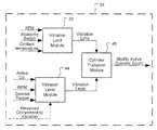
- a control modulemay include a vibration limit module, a vibration level module and a cylinder transition module.
- the vibration limit modulemay determine a vibration limit based upon the vehicle speed (KPH), and a coolant temperature of the engine.
- the vibration level modulemay determine a vibration level based upon at least one of a desired engine torque and the engine RPM.
- the cylinder transition modulemay determine a desired activated cylinder count based upon the vibration limit and the vibration level.
- the control modulemay activate or deactivate cylinders of the engine.
- the vibration modulemay determine the vibration limit based upon a signal from a user actuated economy switch.
- FIG. 1is a schematic illustration of a vehicle according to the present disclosure
- FIG. 2is a block diagram of the control module shown in FIG. 1 ;
- FIGS. 3A and 3Bare a control diagram illustrating steps for controlling the amount of active cylinders according to the present disclosure.
- modulerefers to an application specific integrated circuit (ASIC), an electronic circuit, a processor (shared, dedicated, or group) and memory that execute one or more software or firmware programs, a combinational logic circuit, or other suitable components that provide the described functionality.
- ASICapplication specific integrated circuit
- processorshared, dedicated, or group
- memorythat execute one or more software or firmware programs, a combinational logic circuit, or other suitable components that provide the described functionality.
- Vehicle 10may include an engine 12 in communication with an intake system 14 , a fuel system 16 , and an ignition system 18 .
- the engine 12may be selectively operated in a full cylinder mode and a cylinder deactivation mode.
- the cylinder deactivation mode of the engine 12may generally include operation of the engine 12 firing less than all of the cylinders. For example, if the engine 12 includes eight cylinders 13 , full cylinder mode operation includes operation of the engine 12 firing all eight cylinders 13 and cylinder deactivation mode generally includes operation of the engine 12 firing less than eight cylinders 13 , such as four cylinder operation of the engine 12 .
- the intake system 14may include an intake manifold 20 and a throttle 22 .
- the throttle 22may control an air flow into the engine 12 .
- the fuel system 16may control a fuel flow into the engine 12 and the ignition system 18 may ignite the air/fuel mixture provided to the engine 12 by the intake system 14 and the fuel system 16 .
- the vehicle 10may further include a control module 24 and an electronic throttle control (ETC) 26 .
- the control module 24may be in communication with the engine 12 to monitor an operating speed thereof and a number and duration of cylinder deactivation events.
- the control module 24may additionally be in communication with the ETC 26 to control an air flow into the engine 12 .
- the ETC 26may be in communication with the throttle 22 and may control operation thereof.
- a manifold absolute pressure sensor 28 and a barometric pressure sensor 30may be in communication with the control module 24 and may provide signals thereto indicative of a manifold absolute pressure (MAP) and a barometric pressure (P BARO ), respectively.
- An engine coolant sensor 32may communicate a signal to the control module 24 indicative of an engine temperature.
- a vehicle speed sensor 33may communicate a signal to the control module 24 indicative of a vehicle speed (KPH).
- component accelerometersmay be in communication with the control module 24 and may provide signals thereto indicative of component acceleration.
- the component accelerometers 34may be accelerometers mounted to various components in the vehicle such as a vehicle dashboard, a vehicle seat track, a steering column and/or other components.
- the accelerometers 34may measure real-time acceleration and communicate signals to the control module 24 indicative thereof.
- the accelerometers 34may each be configured to communicate acceleration measurements along multiple axes (such as along the x, y, and z axes etc.).
- An economy switch 38may be in communication with the control module 24 and may provide a signal thereto.
- the economy switch 38may be any switch that may communicate an “ON” and “OFF” status.
- the economy switch 38may be a user actuated switch that allows for increased acceptable values of vibration in the vehicle without modifying an active cylinder count of the engine 12 .
- the economy switch 38may be switched to the “ON” position to improve fuel economy. It is appreciated that the economy switch 38 may take other forms such as a button for example, or other device that can receive an operator input.
- the control module 24may include a vibration limit module 40 , a vibration level module 44 and a cylinder transition module 48 .
- the vibration limit module 40may determine a vibration limit based upon at least one of a vehicle speed (KPH), a signal from the economy switch 38 and a coolant temperature.
- the vibration level module 44may determine a vibration level based upon an active cylinder count (e.g. the amount of cylinders 13 being fired in the engine 12 ), the RPM of the engine 12 , and a desired torque.
- the vibration level module 44may determine a vibration level based upon signals received from the component accelerometers 34 .
- the component accelerometers 34may be provided at desired locations in the vehicle such as at the vehicle seat track, the dashboard, the steering column or elsewhere in the vehicle. It is appreciated that the vibration level module 44 may determine a vibration level based on a combination of inputs from the first implementation and the second implementation.
- the cylinder transition module 48may modify the active cylinder count of the engine 12 based upon the vibration limit and the vibration level.
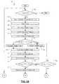
- control logic 100for controlling an amount of active cylinders of the engine 12 based on a component vibration level is illustrated.
- Control logic 100may begin in step 102 where control determines if the engine 12 in on. If the engine 12 is operating, control captures cylinder deactivation variables in step 104 .
- the cylinder deactivation variablesmay include Engine RPM (N eng ), Engine Torque Actual (Tq act ), Engine Torque Desired (Tq des ), Vehicle Speed (KPH), Economy Switch State (SW econ ), Cylinder Count Delivered (Cyl del ), Inlet Air Temperature (T inlet ), Barometric Pressure (P baro ), Engine Coolant Temperature (T coolant ).
- controlsets an activated cylinder count to a delivered cylinder count.
- controldetermines the available torque at standard state (1 Bar, 25° C.).
- the available torque at standard statemay be a function of activated cylinders and an engine RPM.
- controlcompensates the available torque based upon atmospheric pressure measured by the barometric pressure sensor 30 .
- controlcompensates the available torque based upon an ambient temperature.
- controldetermines if a desired torque is greater than the available torque.
- the determinationmay be represented as follows where PTR is a percent torque reserve.
- the PTRmay be used to implement a buffer such that the available torque may be slightly greater than the desired torque. ( Tq des *PTR)> Tq avail ? (4)
- step 116If a product of the desired torque and the PTR is greater than the available torque, the cylinder count is increased in step 116 . If not, the cylinder count is decreased in step 118 .
- controldetermines the available torque at standard state (1 Bar, 25° C.).
- the available torque at standard statemay be a function of activated cylinders and an engine RPM.
- the available torque at standard statemay be represented by equation (1) above.
- controlcompensates the available torque based upon atmospheric pressure measured by the barometric pressure sensor 30 .
- the compensated torquemay be represented by equation (2) above.
- controlcompensates the available torque based upon an ambient temperature.
- the compensated torquemay be represented by equation (3) above.
- controldetermines if a desired torque is greater than the available torque using equation (4) above.
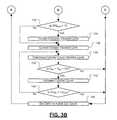
- controldetermines if the activated cylinders are equal to the maximum number of cylinders in the engine 12 in step 128 . If the activated cylinders are equal to the maximum number of cylinders, control loops to step 146 . If the activated cylinders are not equal to the maximum number of cylinders, control loops to step 116 . If the desired torque is not greater than the available torque in step 126 , control determines a vehicle vibration limit in step 130 .
- the vehicle vibration limitmay be a function of vehicle speed (KPH).
- step 132control determines if the economy switch 38 is in the “ON” or active position. If the economy switch 38 is active, control corrects the economy vibration limit in step 134 .
- the vibration limitis increased by a correction factor (F economy ).
- F economycan be calibrated to satisfy any allowable vibration limit.
- a vehicle operatormay wish to tolerate increased vibration in order to gain fuel economy.
- controlmay continue operation of the engine 12 with a reduced active cylinder count, thus increasing fuel economy.
- controlcompensates the vibration limit based upon a coolant temperature of the engine 12 .
- controldetermines a vibration level.
- controlmay implement an open loop control to determine a vibration level.
- the vibration levelmay be determined as a function of engine RPM, engine torque, and a number of active cylinders. The vibration level, therefore, may be determined from a 4D lookup table.
- a vibration mapmay be generated by instrumenting individual driver compartment components (steering column, driver seat track, dashboard, etc.) with accelerometers 34 and operating the vehicle such that the engine 12 goes through a full range of RPM and engine torque.
- the cylinders 13may be locked in a particular state (e.g., 5 cylinder state for an 8 cylinder engine) and a unique vibration map may be generated for each active cylinder state.
- a weighted RMS average vibration(explained in more detail below) may be calculated from outputs of all of the accelerometers 34 .
- An “x-y-z” scatter plotmay be generated for each cylinder count. The scatter plots may be used to generate a 3D table, where the component vibration is a function of engine RPM and engine torque.
- the accelerometers 34are only used during testing to generate the 4D lookup tables for each active cylinder state.
- controlmay implement a closed loop control to determine a vibration level.
- controlmay determine a real-time vibration level based on the signals from the accelerometers 34 .
- the component accelerometers 34may be provided at desired locations in the vehicle such as at the vehicle seat track, the dashboard, the steering column or elsewhere in the vehicle.
- this closed loop controlsome or all of the accelerometers 34 may be provided in the vehicle for communicating real-time vibration levels to the control module 24 .
- the accelerometers 34may provide accelerations in multiple directions (x, y, z etc.).
- accelerometer signals from one or more componentsmay be weighted differently than accelerometer signals from other components.
- the weighting of accelerometer signalsmay be used for both of the open loop and closed loop examples described above. As may be appreciated, it may be more important to quantify and react to a vibration level of one component (such as at a vehicle seat track for example) as compared to another component (such as at a vehicle dashboard for example).
- controldetermines if the vibration level is greater than the vibration limit using the following expression where VO is a hysteresis constant.
- VOvibration offset
- the determinationcan be represented as follows: V lev >V lim +VO? (10)
- controlloops to step 146 . If the vibration level is greater than the vibration limit, control increases cylinder count in step 142 . In step 144 , control determines if the activated cylinders are equal to the maximum number of cylinders in the engine 12 . If the activated cylinders are equal to the maximum number of cylinders, control loops to step 146 . If the activated cylinders are not equal to the maximum number of cylinders, control loops to step 138 . In step 146 , control sets the delivered cylinder count equal to the active cylinder count. Control then loops to step 102 .
Landscapes
- Engineering & Computer Science (AREA)
- Chemical & Material Sciences (AREA)
- Combustion & Propulsion (AREA)
- Mechanical Engineering (AREA)
- General Engineering & Computer Science (AREA)
- Output Control And Ontrol Of Special Type Engine (AREA)
Abstract
Description
Tqavail@std=F(Cylact,Neng) (1)
Tqavail@25C=Tqavail@std*(Pbaro/101.3) (2)
Tqavail=Tqavail@25C*(298/(Tinlet+273)) (3)
(Tqdes*PTR)>Tqavail? (4)
Vlim=F(KPH) (5)
Vlim=Vlim*EVM (6)
Vlim=Vlim*Feconomy (7)
Vlim=Vlim*(F(Tcoolant)) (8)
Vlev=F(Cylact,Neng,Tqdes) (9)
WeightedRMS=a/T*RMS(STz−CAz)+b/T*RMS(SCy−Cay)+c/T*RMS(SCz−CAz)+d/T*RMS(Dz−CAz)+ . . .
Vlev>Vlim+VO? (10)
Claims (13)
Priority Applications (3)
| Application Number | Priority Date | Filing Date | Title |
|---|---|---|---|
| US12/029,669US8108132B2 (en) | 2008-01-04 | 2008-02-12 | Component vibration based cylinder deactivation control system and method |
| DE102008062668.6ADE102008062668B4 (en) | 2008-01-04 | 2008-12-17 | A control module and method for controlling cylinder deactivation based on component vibrations |
| CN2009100018678ACN101476507B (en) | 2008-01-04 | 2009-01-04 | Component vibration based cylinder deactivation control system and method |
Applications Claiming Priority (2)
| Application Number | Priority Date | Filing Date | Title |
|---|---|---|---|
| US1895608P | 2008-01-04 | 2008-01-04 | |
| US12/029,669US8108132B2 (en) | 2008-01-04 | 2008-02-12 | Component vibration based cylinder deactivation control system and method |
Publications (2)
| Publication Number | Publication Date |
|---|---|
| US20090177371A1 US20090177371A1 (en) | 2009-07-09 |
| US8108132B2true US8108132B2 (en) | 2012-01-31 |
Family
ID=40837279
Family Applications (1)
| Application Number | Title | Priority Date | Filing Date |
|---|---|---|---|
| US12/029,669Expired - Fee RelatedUS8108132B2 (en) | 2008-01-04 | 2008-02-12 | Component vibration based cylinder deactivation control system and method |
Country Status (2)
| Country | Link |
|---|---|
| US (1) | US8108132B2 (en) |
| CN (1) | CN101476507B (en) |
Cited By (35)
| Publication number | Priority date | Publication date | Assignee | Title |
|---|---|---|---|---|
| US20120310457A1 (en)* | 2011-06-01 | 2012-12-06 | Hyundai Motor Company | Method and system for cutting fuel for hybrid vehicle |
| US9086020B2 (en) | 2011-10-17 | 2015-07-21 | Tula Technology, Inc. | Firing fraction management in skip fire engine control |
| US9249748B2 (en) | 2012-10-03 | 2016-02-02 | GM Global Technology Operations LLC | System and method for controlling a firing sequence of an engine to reduce vibration when cylinders of the engine are deactivated |
| US9249749B2 (en) | 2012-10-15 | 2016-02-02 | GM Global Technology Operations LLC | System and method for controlling a firing pattern of an engine to reduce vibration when cylinders of the engine are deactivated |
| US9341128B2 (en) | 2014-06-12 | 2016-05-17 | GM Global Technology Operations LLC | Fuel consumption based cylinder activation and deactivation control systems and methods |
| US9376973B2 (en) | 2012-09-10 | 2016-06-28 | GM Global Technology Operations LLC | Volumetric efficiency determination systems and methods |
| US9382853B2 (en) | 2013-01-22 | 2016-07-05 | GM Global Technology Operations LLC | Cylinder control systems and methods for discouraging resonant frequency operation |
| US9416743B2 (en) | 2012-10-03 | 2016-08-16 | GM Global Technology Operations LLC | Cylinder activation/deactivation sequence control systems and methods |
| US9441550B2 (en) | 2014-06-10 | 2016-09-13 | GM Global Technology Operations LLC | Cylinder firing fraction determination and control systems and methods |
| US9458779B2 (en) | 2013-01-07 | 2016-10-04 | GM Global Technology Operations LLC | Intake runner temperature determination systems and methods |
| US9458778B2 (en) | 2012-08-24 | 2016-10-04 | GM Global Technology Operations LLC | Cylinder activation and deactivation control systems and methods |
| US9458780B2 (en) | 2012-09-10 | 2016-10-04 | GM Global Technology Operations LLC | Systems and methods for controlling cylinder deactivation periods and patterns |
| US9494092B2 (en) | 2013-03-13 | 2016-11-15 | GM Global Technology Operations LLC | System and method for predicting parameters associated with airflow through an engine |
| US9534550B2 (en) | 2012-09-10 | 2017-01-03 | GM Global Technology Operations LLC | Air per cylinder determination systems and methods |
| US9556811B2 (en) | 2014-06-20 | 2017-01-31 | GM Global Technology Operations LLC | Firing pattern management for improved transient vibration in variable cylinder deactivation mode |
| US9599047B2 (en) | 2014-11-20 | 2017-03-21 | GM Global Technology Operations LLC | Combination cylinder state and transmission gear control systems and methods |
| US9638121B2 (en) | 2012-08-24 | 2017-05-02 | GM Global Technology Operations LLC | System and method for deactivating a cylinder of an engine and reactivating the cylinder based on an estimated trapped air mass |
| US9650978B2 (en) | 2013-01-07 | 2017-05-16 | GM Global Technology Operations LLC | System and method for randomly adjusting a firing frequency of an engine to reduce vibration when cylinders of the engine are deactivated |
| US9650971B2 (en) | 2010-01-11 | 2017-05-16 | Tula Technology, Inc. | Firing fraction management in skip fire engine control |
| US9719439B2 (en) | 2012-08-24 | 2017-08-01 | GM Global Technology Operations LLC | System and method for controlling spark timing when cylinders of an engine are deactivated to reduce noise and vibration |
| US9726139B2 (en) | 2012-09-10 | 2017-08-08 | GM Global Technology Operations LLC | System and method for controlling a firing sequence of an engine to reduce vibration when cylinders of the engine are deactivated |
| US9739212B1 (en) | 2016-05-06 | 2017-08-22 | Tula Technology, Inc. | Method and apparatus for determining optimum skip fire firing profile with adjustments for ambient temperature |
| US9835096B2 (en) | 2014-08-27 | 2017-12-05 | Honda Motor Co., Ltd. | Apparatus and methods for performing variable displacement control for a vehicular engine |
| US10036333B2 (en) | 2016-05-16 | 2018-07-31 | Ford Global Technologies, Llc | Cylinder deactivation control system |
| US10100754B2 (en) | 2016-05-06 | 2018-10-16 | Tula Technology, Inc. | Dynamically varying an amount of slippage of a torque converter clutch provided between an engine and a transmission of a vehicle |
| US10196994B2 (en) | 2016-05-16 | 2019-02-05 | Ford Global Technologies, Llc | Powertrain control system |
| US20190061736A1 (en)* | 2016-04-26 | 2019-02-28 | Bayerische Motoren Werke Aktiengesellschaft | Method and Device for Operating a Hybrid Vehicle Comprising an Electric Energy Store, an Electric Motor and an Internal Combustion Engine |
| US10227939B2 (en) | 2012-08-24 | 2019-03-12 | GM Global Technology Operations LLC | Cylinder deactivation pattern matching |
| US10246073B2 (en) | 2016-05-16 | 2019-04-02 | Ford Global Technologies, Llc | Control system for a hybrid-electric vehicle |
| US10247121B2 (en) | 2014-03-13 | 2019-04-02 | Tula Technology, Inc. | Method and apparatus for determining optimum skip fire firing profile |
| DE102018113289A1 (en)* | 2017-11-09 | 2019-05-09 | Grammer Ag | Method and system for determining whole-body vibration |
| US10337441B2 (en) | 2015-06-09 | 2019-07-02 | GM Global Technology Operations LLC | Air per cylinder determination systems and methods |
| US20200123987A1 (en)* | 2018-10-18 | 2020-04-23 | Ford Global Technologies, Llc | Method and system for nvh control |
| US10759255B2 (en) | 2016-07-20 | 2020-09-01 | Ford Global Technologies, Llc | Autonomous-vehicle climate-control system |
| US11279265B2 (en) | 2018-09-06 | 2022-03-22 | Honda Motor Co., Ltd | System and method for counteracting vibrations within a vehicle |
Families Citing this family (35)
| Publication number | Priority date | Publication date | Assignee | Title |
|---|---|---|---|---|
| US8131447B2 (en)* | 2008-07-11 | 2012-03-06 | Tula Technology, Inc. | Internal combustion engine control for improved fuel efficiency |
| US8646435B2 (en)* | 2008-07-11 | 2014-02-11 | Tula Technology, Inc. | System and methods for stoichiometric compression ignition engine control |
| US8701628B2 (en) | 2008-07-11 | 2014-04-22 | Tula Technology, Inc. | Internal combustion engine control for improved fuel efficiency |
| US8402942B2 (en)* | 2008-07-11 | 2013-03-26 | Tula Technology, Inc. | System and methods for improving efficiency in internal combustion engines |
| US9689327B2 (en) | 2008-07-11 | 2017-06-27 | Tula Technology, Inc. | Multi-level skip fire |
| US8336521B2 (en)* | 2008-07-11 | 2012-12-25 | Tula Technology, Inc. | Internal combustion engine control for improved fuel efficiency |
| US9020735B2 (en) | 2008-07-11 | 2015-04-28 | Tula Technology, Inc. | Skip fire internal combustion engine control |
| US8616181B2 (en)* | 2008-07-11 | 2013-12-31 | Tula Technology, Inc. | Internal combustion engine control for improved fuel efficiency |
| US8511281B2 (en) | 2009-07-10 | 2013-08-20 | Tula Technology, Inc. | Skip fire engine control |
| WO2012075290A1 (en) | 2010-12-01 | 2012-06-07 | Tula Technology, Inc. | Skip fire internal combustion engine control |
| WO2016048714A1 (en)* | 2014-09-22 | 2016-03-31 | Tula Technology, Inc. | Skip fire transition control |
| US9745905B2 (en) | 2011-10-17 | 2017-08-29 | Tula Technology, Inc. | Skip fire transition control |
| US9080515B2 (en)* | 2012-05-29 | 2015-07-14 | GM Global Technology Operations LLC | System and method for controlling engine torque to prevent driveline bump when a driver depresses an accelerator pedal |
| DE102012104994B4 (en)* | 2012-06-11 | 2024-05-08 | Dr. Ing. H.C. F. Porsche Aktiengesellschaft | Method for operating an internal combustion engine |
| JP5962758B2 (en)* | 2012-06-14 | 2016-08-03 | 日産自動車株式会社 | Control device for internal combustion engine |
| CN102817722B (en)* | 2012-08-07 | 2015-05-20 | 杭州电子科技大学 | Load control method for reducing cylinders of diesel engine |
| US9140622B2 (en)* | 2012-09-10 | 2015-09-22 | GM Global Technology Operations LLC | System and method for controlling a firing sequence of an engine to reduce vibration when cylinders of the engine are deactivated |
| US9222427B2 (en) | 2012-09-10 | 2015-12-29 | GM Global Technology Operations LLC | Intake port pressure prediction for cylinder activation and deactivation control systems |
| US9239024B2 (en) | 2012-09-10 | 2016-01-19 | GM Global Technology Operations LLC | Recursive firing pattern algorithm for variable cylinder deactivation in transient operation |
| US9249747B2 (en) | 2012-09-10 | 2016-02-02 | GM Global Technology Operations LLC | Air mass determination for cylinder activation and deactivation control systems |
| DE102013220185B4 (en)* | 2012-10-15 | 2019-02-07 | GM Global Technology Operations LLC (n. d. Gesetzen des Staates Delaware) | A system and method for controlling a firing pattern of an engine to reduce vibration upon deactivation of cylinders of the engine |
| US9399964B2 (en) | 2014-11-10 | 2016-07-26 | Tula Technology, Inc. | Multi-level skip fire |
| US10400691B2 (en) | 2013-10-09 | 2019-09-03 | Tula Technology, Inc. | Noise/vibration reduction control |
| US20160252023A1 (en)* | 2014-03-13 | 2016-09-01 | Tula Technology, Inc. | Method and apparatus for determining optimum skip fire firing profile with rough roads and acoustic sources |
| US11236689B2 (en) | 2014-03-13 | 2022-02-01 | Tula Technology, Inc. | Skip fire valve control |
| US9841354B2 (en)* | 2014-04-28 | 2017-12-12 | Hong Kong Baptist University | Diagnosis of internal combustion engine performance |
| WO2015175286A1 (en) | 2014-05-12 | 2015-11-19 | Tula Technology, Inc. | Internal combustion engine using variable valve lift and skip fire control |
| US10662883B2 (en) | 2014-05-12 | 2020-05-26 | Tula Technology, Inc. | Internal combustion engine air charge control |
| JP6036750B2 (en)* | 2014-06-04 | 2016-11-30 | トヨタ自動車株式会社 | Control device for internal combustion engine |
| US9874166B2 (en)* | 2014-10-13 | 2018-01-23 | Ford Global Technologies, Llc | Method for controlling vibrations during transitions in a variable displacement engine |
| US9657637B2 (en)* | 2014-10-13 | 2017-05-23 | Ford Global Technologies, Llc | Method for controlling transitions in a variable displacement engine |
| CN109026493B (en)* | 2014-11-10 | 2020-05-15 | 图拉技术公司 | Method for controlling an internal combustion engine and ignition controller |
| US10947917B2 (en)* | 2017-02-16 | 2021-03-16 | Transportation Ip Holdings, Llc | Methods and system for skip-firing of an engine |
| US10493836B2 (en) | 2018-02-12 | 2019-12-03 | Tula Technology, Inc. | Noise/vibration control using variable spring absorber |
| CN113494367B (en)* | 2020-04-01 | 2023-01-13 | 长城汽车股份有限公司 | Cylinder deactivation control method and system for engine and vehicle |
Citations (9)
| Publication number | Priority date | Publication date | Assignee | Title |
|---|---|---|---|---|
| US3440603A (en)* | 1966-07-08 | 1969-04-22 | Herman V Cochran | Vehicle acceleration indicating device |
| US3682001A (en)* | 1970-07-29 | 1972-08-08 | Nissan Motor | Maximum acceleration indicator |
| US3709338A (en)* | 1970-09-28 | 1973-01-09 | E Glen | Single pedal brake-accelerator mechanism with cruise control |
| US3788149A (en)* | 1972-06-26 | 1974-01-29 | Becton Dickinson Co | Low cost resistance gauge accelerometer |
| US4023864A (en)* | 1973-09-20 | 1977-05-17 | Lang Davis Industries, Inc. | Automatic stability control system with strain gauge sensors |
| US5418858A (en)* | 1994-07-11 | 1995-05-23 | Cooper Tire & Rubber Company | Method and apparatus for intelligent active and semi-active vibration control |
| US7140355B2 (en)* | 2004-03-19 | 2006-11-28 | Ford Global Technologies, Llc | Valve control to reduce modal frequencies that may cause vibration |
| US7292932B1 (en)* | 2006-11-13 | 2007-11-06 | Ford Global Technologies, Llc | System and method for controlling speed of an engine |
| US20080276897A1 (en)* | 2007-05-07 | 2008-11-13 | Ford Global Technologies, Llc | System and Method for Operation of an Engine Having Multiple Combustion Modes and Adjustable Balance Shafts |
Family Cites Families (1)
| Publication number | Priority date | Publication date | Assignee | Title |
|---|---|---|---|---|
| CN1904328A (en)* | 2006-08-14 | 2007-01-31 | 张子生 | One body expitaxial varied displacement internal combustion engine |
- 2008
- 2008-02-12USUS12/029,669patent/US8108132B2/ennot_activeExpired - Fee Related
- 2009
- 2009-01-04CNCN2009100018678Apatent/CN101476507B/ennot_activeExpired - Fee Related
Patent Citations (9)
| Publication number | Priority date | Publication date | Assignee | Title |
|---|---|---|---|---|
| US3440603A (en)* | 1966-07-08 | 1969-04-22 | Herman V Cochran | Vehicle acceleration indicating device |
| US3682001A (en)* | 1970-07-29 | 1972-08-08 | Nissan Motor | Maximum acceleration indicator |
| US3709338A (en)* | 1970-09-28 | 1973-01-09 | E Glen | Single pedal brake-accelerator mechanism with cruise control |
| US3788149A (en)* | 1972-06-26 | 1974-01-29 | Becton Dickinson Co | Low cost resistance gauge accelerometer |
| US4023864A (en)* | 1973-09-20 | 1977-05-17 | Lang Davis Industries, Inc. | Automatic stability control system with strain gauge sensors |
| US5418858A (en)* | 1994-07-11 | 1995-05-23 | Cooper Tire & Rubber Company | Method and apparatus for intelligent active and semi-active vibration control |
| US7140355B2 (en)* | 2004-03-19 | 2006-11-28 | Ford Global Technologies, Llc | Valve control to reduce modal frequencies that may cause vibration |
| US7292932B1 (en)* | 2006-11-13 | 2007-11-06 | Ford Global Technologies, Llc | System and method for controlling speed of an engine |
| US20080276897A1 (en)* | 2007-05-07 | 2008-11-13 | Ford Global Technologies, Llc | System and Method for Operation of an Engine Having Multiple Combustion Modes and Adjustable Balance Shafts |
Cited By (45)
| Publication number | Priority date | Publication date | Assignee | Title |
|---|---|---|---|---|
| US9650971B2 (en) | 2010-01-11 | 2017-05-16 | Tula Technology, Inc. | Firing fraction management in skip fire engine control |
| US8666578B2 (en)* | 2011-06-01 | 2014-03-04 | Hyundai Motor Company | Method and system for cutting fuel for hybrid vehicle |
| US20120310457A1 (en)* | 2011-06-01 | 2012-12-06 | Hyundai Motor Company | Method and system for cutting fuel for hybrid vehicle |
| US9086020B2 (en) | 2011-10-17 | 2015-07-21 | Tula Technology, Inc. | Firing fraction management in skip fire engine control |
| US11280276B2 (en) | 2011-10-17 | 2022-03-22 | Tula Technology, Inc. | Firing fraction management in skip fire engine control |
| US10968841B2 (en) | 2011-10-17 | 2021-04-06 | Tula Technology, Inc. | Firing fraction management in skip fire engine control |
| US10508604B2 (en) | 2011-10-17 | 2019-12-17 | Tula Technology, Inc. | Firing fraction management in skip fire engine control |
| US9528446B2 (en) | 2011-10-17 | 2016-12-27 | Tula Technology, Inc. | Firing fraction management in skip fire engine control |
| US9964051B2 (en) | 2011-10-17 | 2018-05-08 | Tula Technology, Inc. | Firing fraction management in skip fire engine control |
| US10227939B2 (en) | 2012-08-24 | 2019-03-12 | GM Global Technology Operations LLC | Cylinder deactivation pattern matching |
| US9719439B2 (en) | 2012-08-24 | 2017-08-01 | GM Global Technology Operations LLC | System and method for controlling spark timing when cylinders of an engine are deactivated to reduce noise and vibration |
| US9458778B2 (en) | 2012-08-24 | 2016-10-04 | GM Global Technology Operations LLC | Cylinder activation and deactivation control systems and methods |
| US9638121B2 (en) | 2012-08-24 | 2017-05-02 | GM Global Technology Operations LLC | System and method for deactivating a cylinder of an engine and reactivating the cylinder based on an estimated trapped air mass |
| US9726139B2 (en) | 2012-09-10 | 2017-08-08 | GM Global Technology Operations LLC | System and method for controlling a firing sequence of an engine to reduce vibration when cylinders of the engine are deactivated |
| US9376973B2 (en) | 2012-09-10 | 2016-06-28 | GM Global Technology Operations LLC | Volumetric efficiency determination systems and methods |
| US9534550B2 (en) | 2012-09-10 | 2017-01-03 | GM Global Technology Operations LLC | Air per cylinder determination systems and methods |
| US9458780B2 (en) | 2012-09-10 | 2016-10-04 | GM Global Technology Operations LLC | Systems and methods for controlling cylinder deactivation periods and patterns |
| US9249748B2 (en) | 2012-10-03 | 2016-02-02 | GM Global Technology Operations LLC | System and method for controlling a firing sequence of an engine to reduce vibration when cylinders of the engine are deactivated |
| US9416743B2 (en) | 2012-10-03 | 2016-08-16 | GM Global Technology Operations LLC | Cylinder activation/deactivation sequence control systems and methods |
| US9249749B2 (en) | 2012-10-15 | 2016-02-02 | GM Global Technology Operations LLC | System and method for controlling a firing pattern of an engine to reduce vibration when cylinders of the engine are deactivated |
| US9458779B2 (en) | 2013-01-07 | 2016-10-04 | GM Global Technology Operations LLC | Intake runner temperature determination systems and methods |
| US9650978B2 (en) | 2013-01-07 | 2017-05-16 | GM Global Technology Operations LLC | System and method for randomly adjusting a firing frequency of an engine to reduce vibration when cylinders of the engine are deactivated |
| US9382853B2 (en) | 2013-01-22 | 2016-07-05 | GM Global Technology Operations LLC | Cylinder control systems and methods for discouraging resonant frequency operation |
| US9494092B2 (en) | 2013-03-13 | 2016-11-15 | GM Global Technology Operations LLC | System and method for predicting parameters associated with airflow through an engine |
| US10941722B2 (en) | 2014-03-13 | 2021-03-09 | Tula Technology, Inc. | Method and apparatus for determining optimum skip fire firing profile |
| US10519876B2 (en) | 2014-03-13 | 2019-12-31 | Tula Technology, Inc. | Controller system and method for selecting a firing fraction for a skip fire controlled internal combustion engine based at least on non-drive train levels of noise, vibration and harshness |
| US10247121B2 (en) | 2014-03-13 | 2019-04-02 | Tula Technology, Inc. | Method and apparatus for determining optimum skip fire firing profile |
| US9441550B2 (en) | 2014-06-10 | 2016-09-13 | GM Global Technology Operations LLC | Cylinder firing fraction determination and control systems and methods |
| US9341128B2 (en) | 2014-06-12 | 2016-05-17 | GM Global Technology Operations LLC | Fuel consumption based cylinder activation and deactivation control systems and methods |
| US9556811B2 (en) | 2014-06-20 | 2017-01-31 | GM Global Technology Operations LLC | Firing pattern management for improved transient vibration in variable cylinder deactivation mode |
| US9835096B2 (en) | 2014-08-27 | 2017-12-05 | Honda Motor Co., Ltd. | Apparatus and methods for performing variable displacement control for a vehicular engine |
| US9599047B2 (en) | 2014-11-20 | 2017-03-21 | GM Global Technology Operations LLC | Combination cylinder state and transmission gear control systems and methods |
| US10337441B2 (en) | 2015-06-09 | 2019-07-02 | GM Global Technology Operations LLC | Air per cylinder determination systems and methods |
| US20190061736A1 (en)* | 2016-04-26 | 2019-02-28 | Bayerische Motoren Werke Aktiengesellschaft | Method and Device for Operating a Hybrid Vehicle Comprising an Electric Energy Store, an Electric Motor and an Internal Combustion Engine |
| US10933860B2 (en)* | 2016-04-26 | 2021-03-02 | Bayerische Motoren Werke Aktiengesellschaft | Method and device for operating a hybrid vehicle comprising an electric energy store, an electric motor and an internal combustion engine |
| US9739212B1 (en) | 2016-05-06 | 2017-08-22 | Tula Technology, Inc. | Method and apparatus for determining optimum skip fire firing profile with adjustments for ambient temperature |
| US10100754B2 (en) | 2016-05-06 | 2018-10-16 | Tula Technology, Inc. | Dynamically varying an amount of slippage of a torque converter clutch provided between an engine and a transmission of a vehicle |
| US10196994B2 (en) | 2016-05-16 | 2019-02-05 | Ford Global Technologies, Llc | Powertrain control system |
| US10246073B2 (en) | 2016-05-16 | 2019-04-02 | Ford Global Technologies, Llc | Control system for a hybrid-electric vehicle |
| US10036333B2 (en) | 2016-05-16 | 2018-07-31 | Ford Global Technologies, Llc | Cylinder deactivation control system |
| US10759255B2 (en) | 2016-07-20 | 2020-09-01 | Ford Global Technologies, Llc | Autonomous-vehicle climate-control system |
| DE102018113289A1 (en)* | 2017-11-09 | 2019-05-09 | Grammer Ag | Method and system for determining whole-body vibration |
| US11279265B2 (en) | 2018-09-06 | 2022-03-22 | Honda Motor Co., Ltd | System and method for counteracting vibrations within a vehicle |
| US10746112B2 (en)* | 2018-10-18 | 2020-08-18 | Ford Global Technologies, Llc | Method and system for NVH control |
| US20200123987A1 (en)* | 2018-10-18 | 2020-04-23 | Ford Global Technologies, Llc | Method and system for nvh control |
Also Published As
| Publication number | Publication date |
|---|---|
| CN101476507A (en) | 2009-07-08 |
| US20090177371A1 (en) | 2009-07-09 |
| CN101476507B (en) | 2012-02-15 |
Similar Documents
| Publication | Publication Date | Title |
|---|---|---|
| US8108132B2 (en) | Component vibration based cylinder deactivation control system and method | |
| US7703437B2 (en) | Electronic control device for controlling the internal combustion engine in a motor vehicle | |
| US7836870B2 (en) | Method for controlling an internal combustion engine of a motor vehicle | |
| US7861686B2 (en) | Fuel injection control apparatus and fuel injection control method | |
| CN101655044B (en) | Engine control using cylinder pressure differential | |
| US7668687B2 (en) | Systems and methods for compensating pressure sensor errors | |
| JP2008069714A (en) | Control device for internal combustion engine | |
| US7962277B2 (en) | Method and device for operating an internal combustion engine | |
| US20170276083A1 (en) | Misfire detecting system for engine | |
| US20090281706A1 (en) | Engine Optimisation Method And Apparatus | |
| US8364385B2 (en) | Cylinder pressure sensor reset systems and methods | |
| JP2013040777A (en) | Cylinder inner pressure detection device of internal combustion engine | |
| JPH0823333B2 (en) | Ignition timing control device for internal combustion engine | |
| CN102052188B (en) | In-cylinder pressure sensor signal is used to control the method and system of motor | |
| KR20100002265A (en) | Controller of internal combustion engine | |
| US10495015B2 (en) | Diagnostic device | |
| US6758179B1 (en) | Method and apparatus for controlling a variable valve system for an internal combustion engine | |
| US20010020465A1 (en) | Method for detecting combustion misfires and cylinder equalization in internal combustion engines with knock control | |
| EP2570636B1 (en) | Control device for internal combustion engine | |
| JP2006220139A (en) | Control device and control method for internal combustion engine | |
| US7203591B2 (en) | Method for controlling an internal combustion engine | |
| US9051894B2 (en) | Control device for internal combustion engine | |
| KR101108453B1 (en) | Internal combustion engine control apparatus | |
| DE102008062668B4 (en) | A control module and method for controlling cylinder deactivation based on component vibrations | |
| US20080257305A1 (en) | System for controlling fuel injectors |
Legal Events
| Date | Code | Title | Description |
|---|---|---|---|
| AS | Assignment | Owner name:GM GLOBAL TECHNOLOGY OPERATIONS, INC., MICHIGAN Free format text:ASSIGNMENT OF ASSIGNORS INTEREST;ASSIGNOR:REINKE, PAUL E;REEL/FRAME:020496/0526 Effective date:20080124 | |
| FEPP | Fee payment procedure | Free format text:PAYOR NUMBER ASSIGNED (ORIGINAL EVENT CODE: ASPN); ENTITY STATUS OF PATENT OWNER: LARGE ENTITY | |
| AS | Assignment | Owner name:WILMINGTON TRUST COMPANY, DELAWARE Free format text:SECURITY AGREEMENT;ASSIGNOR:GM GLOBAL TECHNOLOGY OPERATIONS, INC.;REEL/FRAME:025324/0475 Effective date:20101027 | |
| AS | Assignment | Owner name:GM GLOBAL TECHNOLOGY OPERATIONS LLC, MICHIGAN Free format text:CHANGE OF NAME;ASSIGNOR:GM GLOBAL TECHNOLOGY OPERATIONS, INC.;REEL/FRAME:025781/0211 Effective date:20101202 | |
| ZAAA | Notice of allowance and fees due | Free format text:ORIGINAL CODE: NOA | |
| ZAAB | Notice of allowance mailed | Free format text:ORIGINAL CODE: MN/=. | |
| STCF | Information on status: patent grant | Free format text:PATENTED CASE | |
| AS | Assignment | Owner name:GM GLOBAL TECHNOLOGY OPERATIONS LLC, MICHIGAN Free format text:RELEASE BY SECURED PARTY;ASSIGNOR:WILMINGTON TRUST COMPANY;REEL/FRAME:034384/0758 Effective date:20141017 | |
| FPAY | Fee payment | Year of fee payment:4 | |
| MAFP | Maintenance fee payment | Free format text:PAYMENT OF MAINTENANCE FEE, 8TH YEAR, LARGE ENTITY (ORIGINAL EVENT CODE: M1552); ENTITY STATUS OF PATENT OWNER: LARGE ENTITY Year of fee payment:8 | |
| FEPP | Fee payment procedure | Free format text:MAINTENANCE FEE REMINDER MAILED (ORIGINAL EVENT CODE: REM.); ENTITY STATUS OF PATENT OWNER: LARGE ENTITY | |
| LAPS | Lapse for failure to pay maintenance fees | Free format text:PATENT EXPIRED FOR FAILURE TO PAY MAINTENANCE FEES (ORIGINAL EVENT CODE: EXP.); ENTITY STATUS OF PATENT OWNER: LARGE ENTITY | |
| STCH | Information on status: patent discontinuation | Free format text:PATENT EXPIRED DUE TO NONPAYMENT OF MAINTENANCE FEES UNDER 37 CFR 1.362 | |
| FP | Lapsed due to failure to pay maintenance fee | Effective date:20240131 |