US8108052B2 - Percutaneous leads with laterally displaceable portions, and associated systems and methods - Google Patents
Percutaneous leads with laterally displaceable portions, and associated systems and methodsDownload PDFInfo
- Publication number
- US8108052B2 US8108052B2US12/129,078US12907808AUS8108052B2US 8108052 B2US8108052 B2US 8108052B2US 12907808 AUS12907808 AUS 12907808AUS 8108052 B2US8108052 B2US 8108052B2
- Authority
- US
- United States
- Prior art keywords
- percutaneous
- deployment axis
- diameter
- stylet
- less
- Prior art date
- Legal status (The legal status is an assumption and is not a legal conclusion. Google has not performed a legal analysis and makes no representation as to the accuracy of the status listed.)
- Active, expires
Links
- 238000000034methodMethods0.000titleabstractdescription14
- 238000002513implantationMethods0.000claimsdescription6
- 239000012783reinforcing fiberSubstances0.000claimsdescription4
- 210000000278spinal cordAnatomy0.000description16
- 230000000638stimulationEffects0.000description16
- 210000001519tissueAnatomy0.000description10
- 230000001537neural effectEffects0.000description8
- 230000008901benefitEffects0.000description7
- 238000002560therapeutic procedureMethods0.000description7
- 230000000926neurological effectEffects0.000description6
- 210000000273spinal nerve rootAnatomy0.000description6
- 238000004891communicationMethods0.000description5
- 230000004936stimulating effectEffects0.000description4
- 208000002193PainDiseases0.000description3
- 210000003205muscleAnatomy0.000description3
- 210000003594spinal gangliaAnatomy0.000description3
- 238000013459approachMethods0.000description2
- 230000005674electromagnetic inductionEffects0.000description2
- 230000005012migrationEffects0.000description2
- 238000013508migrationMethods0.000description2
- 210000005036nerveAnatomy0.000description2
- 230000008569processEffects0.000description2
- 208000020446Cardiac diseaseDiseases0.000description1
- 208000000094Chronic PainDiseases0.000description1
- 208000036829Device dislocationDiseases0.000description1
- 208000016285Movement diseaseDiseases0.000description1
- 208000008238Muscle SpasticityDiseases0.000description1
- 206010028980NeoplasmDiseases0.000description1
- 210000003484anatomyAnatomy0.000description1
- 230000004323axial lengthEffects0.000description1
- 210000004556brainAnatomy0.000description1
- 201000011510cancerDiseases0.000description1
- 239000002131composite materialSubstances0.000description1
- 230000001010compromised effectEffects0.000description1
- 230000001054cortical effectEffects0.000description1
- 230000008878couplingEffects0.000description1
- 238000010168coupling processMethods0.000description1
- 238000005859coupling reactionMethods0.000description1
- 238000010586diagramMethods0.000description1
- 208000037265diseases, disorders, signs and symptomsDiseases0.000description1
- 208000035475disorderDiseases0.000description1
- 210000001951dura materAnatomy0.000description1
- 230000006870functionEffects0.000description1
- 208000019622heart diseaseDiseases0.000description1
- 239000007943implantSubstances0.000description1
- 238000003780insertionMethods0.000description1
- 230000037431insertionEffects0.000description1
- 238000002955isolationMethods0.000description1
- 210000004705lumbosacral regionAnatomy0.000description1
- 230000015654memoryEffects0.000description1
- 238000012986modificationMethods0.000description1
- 230000004048modificationEffects0.000description1
- 210000000653nervous systemAnatomy0.000description1
- 210000002569neuronAnatomy0.000description1
- 230000002787reinforcementEffects0.000description1
- 208000018198spasticityDiseases0.000description1
- 239000000758substrateSubstances0.000description1
- 230000001225therapeutic effectEffects0.000description1
Images


Classifications
- A—HUMAN NECESSITIES
- A61—MEDICAL OR VETERINARY SCIENCE; HYGIENE
- A61N—ELECTROTHERAPY; MAGNETOTHERAPY; RADIATION THERAPY; ULTRASOUND THERAPY
- A61N1/00—Electrotherapy; Circuits therefor
- A61N1/02—Details
- A61N1/04—Electrodes
- A61N1/05—Electrodes for implantation or insertion into the body, e.g. heart electrode
- A61N1/0551—Spinal or peripheral nerve electrodes
- A61N1/0558—Anchoring or fixation means therefor
Definitions
- the present disclosureis directed generally to percutaneous leads with laterally displaceable portions, and associated systems and methods.
- Implantable neurological stimulation systemsgenerally have an implantable pulse generator and one or more electrode leads that deliver electrical pulses to neurological tissue or muscle tissue.
- implantable pulse generatorFor example, several neurological stimulation systems for spinal cord stimulation (SCS) have cylindrical leads that include a lead body with a circular cross-sectional shape and one or more conductive rings spaced apart from each other at the distal end of the lead body. The conductive rings operate as individual electrodes.
- SCS leadsare implanted percutaneously through a large needle inserted into the epidural space, with or without the assistance of a stylet.
- One concern of such leadsis that the leads may not remain in the desired position after being implanted. This is undesirable because, if the leads migrate from the initial implantation site, the stimulation provided by the electrodes may no longer be directed to the appropriate target tissue. Accordingly, the efficacy of the treatment can be significantly compromised.
- Paddle leadstypically have a relatively flat body with electrodes arranged on one side of the body. Paddle leads are commonly used for cortical stimulation and SCS applications. Large paddle leads are desirable because they cover more neurological structures and, in at least some cases, may be more stable and less subject to migration than cylindrical leads. However, large paddle leads are not well suited to percutaneous implantation. As a result, large paddle leads are often surgically implanted using highly invasive procedures that are costly and can lead to patient complications.
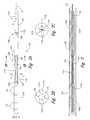
- FIG. 1is a schematic diagram of an implantable spinal stimulation system having a lead body positioned at the spine in accordance with an embodiment of the present disclosure.
- FIG. 2Ais a partially schematic illustration of a lead body configured in accordance with an embodiment of the disclosure.
- FIG. 2Bis a partially schematic, transverse cross-sectional illustration of a lead body taken substantially along line 2 B- 2 B of FIG. 2A .
- FIG. 2Cis a partially schematic, transverse cross-sectional illustration of a lead body having a diameter configured in accordance with another embodiment of the disclosure
- FIG. 3is a partially schematic, axial cross-sectional illustration of an embodiment of the lead body shown in FIG. 2A .
- FIG. 4Ais a partially schematic illustration of a lead body placed at the lumbar region of a patient's spine in accordance with an embodiment of the disclosure.
- FIG. 4Bis a partially schematic, cross-sectional illustration of the patient's spine illustrating representative locations of lead bodies in accordance with embodiments of the disclosure.
- FIG. 5is a partially schematic illustration of a lead body having an intermediate portion that includes a ribbon cable in accordance with an embodiment of the disclosure.
- FIG. 6is a partially schematic illustration of a lead body having an intermediate portion that includes a reinforced electrical link in accordance with an embodiment of the disclosure.
- FIG. 7is partially schematic, isometric illustration of a bayonet device for releaseably securing a delivery device to a lead body during percutaneous insertion, in accordance with an embodiment of the disclosure.
- implantable leads for stimulating neural structuresare described below with reference to implantable leads for stimulating neural structures, methods for implanting leads, and methods for stimulating a target neural site of a patient.
- the leadsmay in some instances be used for stimulating other neurological structures, and/or other tissue (e.g., muscle tissue).
- tissuee.g., muscle tissue.
- Several embodimentscan have configurations, components or procedures different than those described in this section, and other embodiments may eliminate particular components or procedures. A person of ordinary skill in the relevant art, therefore, will understand that the invention may have other embodiments with additional elements, and/or may have other embodiments without several of the features shown and described below with reference to FIGS. 1-7 .
- a patient treatment device in accordance with a particular embodimentincludes a lead body having three percutaneous portions.
- the percutaneous portionsinclude a first portion carrying an electrode and having a first diameter, a second portion spaced apart from the first portion and having a second diameter, and a third portion positioned between the first and second portions along a deployment axis.
- the third portionhas a third diameter less than the first and second diameters, and a stiffness in a direction transverse to the deployment axis that is less than the stiffness of the first portion transverse to the deployment axis, and less than a stiffness of the second portion transverse to the deployment axis.
- the reduced diameter and reduced stiffness of the intermediate third portioncan provide strain relief and reduces the likelihood that the first portion, which is typically located at or near the stimulation site, will become displaced from the stimulation site.
- the intermediate portioncan allow relative movement between the first portion located at the stimulation site, and the second portion, which may be spaced apart from the stimulation site. Such relative movement can occur when the patient moves (e.g., bends or twists) in a certain manner.
- the third portionincludes a flexible, electrical link that is coupled to the electrode and is unsupported between the first and second portions in a direction transverse to the deployment axis.
- the electrical linkcan include, for example, an insulated wire or a ribbon of insulated wires.
- the third portionalso includes an axial reinforcing fiber arranged along the wire(s).
- the lead bodyincludes a first axial aperture extending into the first portion, and a second axial aperture extending through the second portion.
- the delivery devicecan include a stylet that is removably received in both the first and second apertures.
- the first portion and the styletcan be releaseably coupled to each other with a bayonet fitting, and can be separated from each other via relative twisting and axial movement of the stylet relative to the first portion.
- a representative methodincludes delivering a lead body into a patient's body so that a first portion of the lead body having a first diameter and carrying an electrode is proximate to a spinal stimulation site, a second portion of the lead body having a second diameter is positioned radially outwardly from the first portion, and a third portion of the lead body is positioned between the first and second portions.
- the third portioncan have a third diameter less than both the first and second diameters.
- the methodcan further include at least partially fixing the first portion, the second portion, or both the first and second portions to the patient's body, while allowing the third portion to accommodate relative movement between the first and second portions.
- the first portion of the lead bodycan be positioned within the spinal canal, and the second portion of the lead body can be positioned external to the spinal canal.
- the electrode carried by the first portioncan be located in electrical communication with dorsal root neurons, in a gutter along the spinal cord, or in a dorsal root entry zone.
- FIG. 1schematically illustrates a representative treatment system 100 for providing relief from chronic pain and/or other conditions, arranged relative to the general anatomy of a patient's spinal cord 191 .
- the system 100can include a pulse generator 101 implanted subcutaneously within a patient 190 and coupled to a lead 109 .
- the lead 109can include a lead body 110 that carries features for delivering therapy to the patient 190 after implantation.
- the pulse generator 101can be connected directly to the lead body 110 or it can be coupled to the lead body 110 via a communication link 102 .
- the term lead bodyincludes any of a number of suitable substrates and/or support members that carry devices for providing therapy signals to the patient 190 .
- the lead body 110can include one or more electrodes or electrical contacts that direct electrical signals into the patient's tissue to provide for patient relief.
- the lead body 110can carry other devices that direct electrical signals and/or other types of signals to the patient 190 .
- the pulse generator 101can transmit signals to the lead body 110 that up-regulate (e.g. stimulate) and/or down-regulate (e.g. block) target nerves.
- the pulse generator 101can include a machine- (e.g., computer-) readable medium containing instructions for generating and transmitting suitable therapy signals.
- the pulse generator 101 and/or other elements of the system 100can include one or more processors, memories and/or input/output devices.
- the pulse generator 101can include multiple portions, e.g., for directing signals in accordance with multiple signal delivery parameters, housed in a single housing (as shown in FIG. 1 ), or in multiple housings. Representative signal delivery parameters are disclosed in pending U.S. Provisional Application No. 60/985,353, filed Nov. 5, 2007, assigned to the assignee of the present application, and incorporated herein by reference.
- the pulse generator 101can obtain power to generate the therapy signals from an external power source 103 .
- the external power source 103can transmit power to the implanted pulse generator 101 using electromagnetic induction (e.g., RF signals).
- the external power source 103can include an external coil 104 that communicates with a corresponding internal coil (not shown) within the implantable pulse generator 101 .
- the external power source 103can be portable for ease of use.
- the pulse generator 101can obtain the power to generate therapy signals from an internal power source, in addition to or in lieu of the external power source 103 .
- the implanted pulse generator 101can include a non-rechargeable battery or a rechargeable battery to provide such power.
- the internal power sourceincludes a rechargeable battery
- the external power source 103can be used to recharge the battery.
- the external power source 103can in turn be recharged from a suitable power source (e.g., conventional wall power).
- an external programmer(not shown) can communicate with the implantable pulse generator 101 via electromagnetic induction. Accordingly, a practitioner can update the therapy instructions provided by the pulse generator 101 .
- the patientmay also have control over at least some therapy functions, e.g., starting and/or stopping the pulse generator 101 .
- FIG. 2Ais a partially schematic, side elevation view of the lead body 110 configured in accordance with a particular embodiment.
- the lead body 110can include a first or distal portion 111 a , a second or proximal portion 111 b , and an intermediate third portion 111 c located between the first and second portions 111 a , 111 b .
- the first portion 111 acan carry signal delivery electrodes 112 , or other features configured to deliver therapeutic signals to the patient.
- the second portion 111 bcan include connection terminals 113 or other features configured to facilitate communication with the implantable pulse generator 101 ( FIG. 1 ).
- the third portion 111 ccan include a link, e.g., an electrical link 108 that provides signal communication between the connection terminals 113 of the second portion 111 b and the signal delivery electrodes 112 of the first portion 111 a.
- the first portion 111 acan include signal delivery electrodes 112 that have an annular or ring shape and are exposed at the outer circumferential surface of the first portion 111 a , as shown in FIG. 2A .
- the signal delivery electrodes 112can have other configurations, e.g., the electrodes 112 can have a flat or curved disc shape.
- the first portion 111 acan have an overall diameter D 1 which is sized to allow the first portion 111 a to pass through the lumen of a delivery catheter or other delivery device.
- the first portion 111 acan also include a first fixation device 115 a to secure or at least partially secure the first portion 111 a in position at a target site.
- the first fixation device 115 acan include one or more tines, or an annular cup that faces proximally (rightward as shown in FIG. 2A ) to resist axial motion. In other embodiments, the first fixation device 115 a can include other features.
- the second portion 111 bcan include the connection terminals 113 described above, and can have an overall diameter D 2 .
- the diameter D 2 of the second portion of 111 bcan be approximately the same as the diameter D 1 of the first portion of 111 a .
- the second portion 111 bcan include a second fixation device 115 b , for example, one or more sutures 106 that secure or at least partially secure the second portion 111 b in position.
- Each of the first and second portions 111 a , 111 bcan include rounded, convex external surfaces 105 (e.g., at the proximal end of the first portion 111 a and/or at the distal end of the second portion 111 b ) that are exposed to patient tissue and, due to the rounded shapes of these surfaces, facilitate moving the lead body 110 in the patient's body.
- the first portion 111 a , the second portion 111 b , and the third portion 111 ccan be arranged along a deployment axis A.
- the electrical link 108can include one or more wires 114 connected between the signal delivery electrodes 112 at the first portion 111 a and the connection terminals 113 at the second portion 111 b .
- each of the individual wires 114is independently insulated, relatively thin, and movable relative to the other wires 114 .
- the third portion 111 ccan have a stiffness transverse to the deployment axis A, (indicated by arrows T), that is less than a corresponding stiffness of the first portion 111 a and/or the second portion 111 b in the same direction.
- the third portion 111 cis less stiff (or more flexible) than both the first portion 111 a and the second portion 111 b .
- This arrangementcan allow the first portion 111 a and the second portion 111 b to be independently displaced transversely relative to each other.
- the third portion 111 ccan be flexible enough to allow the second portion 111 b to move without disturbing the position of the first portion 111 a .
- the third portion 111 cincludes no structures that extend axially the length of the third portion, other than the wires 114 .
- the third portion 111 cneed not include a shaft that disposed around the wires 114 , which is unlike existing leads.
- An advantage of this arrangementis that it can further increase the flexibility of the third portion 111 c and reduce the likelihood that motion of the second portion 111 b will cause the first portion 111 a to move.
- the third portion 111 chas a diameter D 3 that is less than the diameter D 1 of the first portion 111 a , and/or less than the diameter D 2 of the second portion 111 b .
- the diameter D 3 of the third portion 111 ccan be an envelope that includes each of the wires 114 as they lie in position.
- the diameter D 3can be an effective diameter corresponding to the minimal cross-sectional area of the wires 114 , assuming the wires 114 are positioned in a compact (e.g., surface-to-surface) arrangement.
- the diameter D 3can be significantly less than the diameters D 1 and D 2 to facilitate the additional flexibility of the third portion 111 c relative to the first portion 111 a and the second portion 111 b .
- the diameter D 3can be one half, one quarter, or less than one quarter of the diameters D 1 and D 2 .
- FIG. 3is a cross-sectional illustration of the lead body 110 positioned within a lumen 121 of a delivery catheter 120 .
- the first portion 111 acan include a first aperture 116 a
- the second portion 111 bcan include a second aperture 116 b
- a delivery device 130e.g., a stylet
- the third portion 111 cincludes wires 114
- the delivery device 130can pass alongside, around and/or through interstices between the wires 114 . Accordingly, the third portion 111 c in this embodiment need not include a defined, axially-extending aperture.
- the catheter 120is positioned percutaneously within the patient, and the delivery device 130 is used to push the lead body 110 through the catheter 120 and into the patient.
- the lead delivery device 130can be temporarily secured to the lead body 110 during delivery, as described below with reference to FIG. 7 .
- the delivery device 130is then removed by withdrawing it through the first aperture 116 a and the second aperture 116 b , leaving the lead body 110 in place in the patient.
- the lead body 110can be secured to the patient using any of the fixation devices 115 a , 115 b described above with reference to FIG. 2A .
- FIG. 4Ais a partially schematic illustration of the lower portion of the patient's spine, illustrating the lower lumbar vertebrae.
- a lead body 110 in accordance with a particular embodimentis shown in a representative percutaneously-delivered position at the spinal cord 191 .
- the lead body 110is positioned alongside the spinal cord 191 , with the first portion 111 a located within the spinal column 192 , the second portion 111 b located outside the spinal column 192 , and the third portion 111 c coupled between the first portion 111 a and the second portion 111 b .
- the first portion 111 acan be positioned at a target site for delivering stimulation signals to target neural populations, and the second portion 111 b can be positioned in or adjacent to muscle tissue, ligamentous tissue, and/or other tissue and secured in place.
- the second portion 111 bcan be electrically connected directly to a pulse generator 101 , or it can be coupled to the pulse generator 101 with an intermediate communication link 102 ( FIG. 1 ), such as an extension.
- the second portion 111 bcan be located radially (e.g., laterally) outwardly from the first portion 111 a so that it is offset laterally from the spinal column 192 to facilitate securing it to non-neural tissue.
- the third portion 111 ccan flex in a lateral or radial direction to accommodate the radial offset of the second portion 111 b relative to the first portion 111 a .
- the third portion 111 ccan accommodate such relative movement due to its increased transverse flexibility.
- the axial length of the first portion 111 acan be relatively short, e.g., just long enough to support the electrodes 112 for providing the target electrical stimulation to the target neural population.
- the length of the first portion 111 acan be less than that of conventional lead bodies so that the first portion 111 a may be secured in place without being displaced by a bulky proximal portion.
- the isolation provided by the third portion 111 ccan facilitate this arrangement.
- FIG. 4Bis a cross-sectional illustration of the spinal cord 191 and an adjacent vertebra 195 (based generally on information from Crossman and Neary, “Neuroanatomy,” 1995 (publ. by Churchill Livingstone)), along with selected representative locations for representative lead bodies 110 (shown as lead bodies 110 a - 111 c ) in accordance with several embodiments of the disclosure.
- the spinal cord 191is located between a ventrally located vertebral body 196 and the dorsally located transverse process 198 and spinous process 197 .
- Arrows V and Didentify ventral and dorsal directions, respectively.
- the spinal cord 191itself is located within the dura mater 199 , which also surrounds portions of the nerves exiting the spinal cord 191 , including the dorsal roots 193 and dorsal root ganglia 194 .
- a lead body 110 acan be positioned centrally in a lateral direction (e.g., aligned with the spinal cord midline 189 ) to provide signals directly to the spinal cord 191 .
- the lead bodycan be located laterally from the midline 189 .
- the lead bodycan be positioned proximate to the dorsal root entry zone 188 , or proximate to the dorsal root 193 (as indicated generally by lead body 110 b ), and/or proximate to the dorsal root ganglion 194 (as indicated by lead body 110 c ).
- Other suitable locations for the lead body 110include the “gutter,” also located laterally from the midline 189 and medially from the dorsal root ganglion 194 .
- at least part of the first portion 111 amay extend outwardly in a lateral direction, rather than straight into or out of the plane of FIG. 4B .
- the lead bodiesmay have other locations proximate to the spinal cord 191 and/or proximate to other target neural populations.
- devices having any of the characteristics described hereinmay be used to direct signals to tissues outside the patient's nervous system.
- the first portion 111 a of the lead body 110can be positioned epidurally (or subdurally) proximate to a target neural population at the spinal cord 191 while the second portion 111 b is positioned radially outwardly from the spinal cord 191 , and while the third portion 111 c provides a flexible coupling between the first and second portions.
- FIG. 5illustrates a lead body 110 having a third portion 511 c that includes an electrical link 508 configured in accordance with another embodiment of the disclosure.
- the electrical link 508includes wires 514 that are not individually movable relative to each other, as was the case in the arrangement discussed above with reference to FIG. 2A .
- the wires 514can be arranged in a ribbon cable 517 or other composite structure that fixes each of the wires 514 relative to each other.
- An expected advantage of this arrangementis that it may be easier to control the locations of the wires 514 when they are fixed relative to each other.
- an advantage of the arrangement described above with reference to FIG. 2Ais that the ability of individual wires 114 to move relative to each other can further increase the flexibility of the third portion 111 c in the transverse direction T. Accordingly, the practitioner can select the arrangement expected to produce the best results for an individual patient.
- FIG. 6is a partially schematic, side elevation view of a lead body 110 having a third portion 611 c configured in accordance with still another embodiment.
- the third portion 611 cincludes an electrical link 608 having multiple wires 614 and a transverse flexibility controlled by one or more additional features.
- the wires 614can be bundled together so as not to move relative to each other, and/or can further include a reinforcing fiber 618 that further controls lateral flexibility.
- the third portion 611 ccan include a casing 619 that surrounds the wires 614 .
- the casing 619can also control lateral flexibility of the third portion 611 c , while still providing the third portion 611 c with greater lateral flexibility than that of either the first portion 111 a or the second portion 111 b .
- the practitionercan select an arrangement suitable for a particular patient based on the expected level of desired transverse flexibility.
- the lead body 110can be delivered percutaneously to the patient via a delivery device 130 , as was discussed above with reference to FIG. 3 .
- FIG. 7is a partially schematic, isometric illustration of a particular arrangement by which the delivery device 130 can be releaseably secured to the first portion 111 a of the lead body 110 during implantation.
- the arrangementcan include a bayonet device 740 that facilitates the releaseable connection.
- the bayonet device 740can include a bayonet receptacle 742 positioned in a distal end of the first portion 111 a , and a bayonet fitting 741 carried by the delivery device 130 .
- the bayonet receptacle 742can include an entry 743 and a chamber 744 accessible via the entry 743 .
- the entry 743can have a slot shape or other shape that corresponds to the non-isodiametric shape of the bayonet fitting 741 .
- the chamber 744can have a cylindrical shape that allows the bayonet fitting 741 to be rotated about the deployment axis A once inside the chamber 744 . Accordingly, in operation, the delivery device 130 can be secured to the first portion 111 a by positioning the bayonet fitting 741 as shown in FIG. 7 , inserting it through the entry 743 and into the chamber 744 , and rotating the delivery device 130 relative to the first portion 111 a as indicated by arrow R 1 .
- the delivery device 130can be rotated by 90°. In this orientation, the bayonet fitting 741 cannot be removed from the first portion 111 a by axial motion alone. Accordingly, the delivery device 130 can be moved axially forward or backward until the first portion 111 a has the desired axial position. Once the first portion 111 a has the desired axial position, the practitioner can rotate the delivery device 130 in the opposite direction, as indicated by arrow R 2 , and withdraw the bayonet fitting 741 from the bayonet receptacle 742 .
- An expected advantage of the foregoing arrangement when compared to conventional stylet arrangementsis that it can allow the practitioner to move the first portion 111 a both forward and backward during the positioning task, without decoupling the delivery device 130 from the first portion 111 a.
- the lead body portions 111 a - 111 ccan have other shapes that facilitate an offset and/or relative lateral movement between the first portion 111 a and the second portion 111 b .
- Certain aspects of the disclosure described in the context of particular embodimentsmay be combined or eliminated in other embodiments.
- the bayonet fitting shown in FIG. 7may be included with any of the devices shown in FIGS. 1-6 .
Landscapes
- Health & Medical Sciences (AREA)
- Neurology (AREA)
- Neurosurgery (AREA)
- Orthopedic Medicine & Surgery (AREA)
- Cardiology (AREA)
- Heart & Thoracic Surgery (AREA)
- Engineering & Computer Science (AREA)
- Biomedical Technology (AREA)
- Nuclear Medicine, Radiotherapy & Molecular Imaging (AREA)
- Radiology & Medical Imaging (AREA)
- Life Sciences & Earth Sciences (AREA)
- Animal Behavior & Ethology (AREA)
- General Health & Medical Sciences (AREA)
- Public Health (AREA)
- Veterinary Medicine (AREA)
- Electrotherapy Devices (AREA)
Abstract
Description
Claims (19)
Priority Applications (3)
| Application Number | Priority Date | Filing Date | Title |
|---|---|---|---|
| US12/129,078US8108052B2 (en) | 2008-05-29 | 2008-05-29 | Percutaneous leads with laterally displaceable portions, and associated systems and methods |
| PCT/US2009/045678WO2009146424A1 (en) | 2008-05-29 | 2009-05-29 | Percutaneous leads with laterally displaceable portions, and associated systems and methods |
| US13/362,741US20120185026A1 (en) | 2008-05-29 | 2012-01-31 | Percutaneous leads with laterally displaceable portions, and associated systems and methods |
Applications Claiming Priority (1)
| Application Number | Priority Date | Filing Date | Title |
|---|---|---|---|
| US12/129,078US8108052B2 (en) | 2008-05-29 | 2008-05-29 | Percutaneous leads with laterally displaceable portions, and associated systems and methods |
Related Child Applications (1)
| Application Number | Title | Priority Date | Filing Date |
|---|---|---|---|
| US13/362,741DivisionUS20120185026A1 (en) | 2008-05-29 | 2012-01-31 | Percutaneous leads with laterally displaceable portions, and associated systems and methods |
Publications (2)
| Publication Number | Publication Date |
|---|---|
| US20090299444A1 US20090299444A1 (en) | 2009-12-03 |
| US8108052B2true US8108052B2 (en) | 2012-01-31 |
Family
ID=40889506
Family Applications (2)
| Application Number | Title | Priority Date | Filing Date |
|---|---|---|---|
| US12/129,078Active2030-02-16US8108052B2 (en) | 2008-05-29 | 2008-05-29 | Percutaneous leads with laterally displaceable portions, and associated systems and methods |
| US13/362,741AbandonedUS20120185026A1 (en) | 2008-05-29 | 2012-01-31 | Percutaneous leads with laterally displaceable portions, and associated systems and methods |
Family Applications After (1)
| Application Number | Title | Priority Date | Filing Date |
|---|---|---|---|
| US13/362,741AbandonedUS20120185026A1 (en) | 2008-05-29 | 2012-01-31 | Percutaneous leads with laterally displaceable portions, and associated systems and methods |
Country Status (2)
| Country | Link |
|---|---|
| US (2) | US8108052B2 (en) |
| WO (1) | WO2009146424A1 (en) |
Cited By (35)
| Publication number | Priority date | Publication date | Assignee | Title |
|---|---|---|---|---|
| US8731676B2 (en) | 2011-05-19 | 2014-05-20 | Neuros Medical, Inc. | High-frequency electrical nerve block |
| US9101769B2 (en) | 2011-01-03 | 2015-08-11 | The Regents Of The University Of California | High density epidural stimulation for facilitation of locomotion, posture, voluntary movement, and recovery of autonomic, sexual, vasomotor, and cognitive function after neurological injury |
| US9101768B2 (en) | 2013-03-15 | 2015-08-11 | Globus Medical, Inc. | Spinal cord stimulator system |
| US9295841B2 (en) | 2011-05-19 | 2016-03-29 | Meuros Medical, Inc. | High-frequency electrical nerve block |
| US9308022B2 (en) | 2012-12-10 | 2016-04-12 | Nevro Corporation | Lead insertion devices and associated systems and methods |
| US9393409B2 (en) | 2011-11-11 | 2016-07-19 | Neuroenabling Technologies, Inc. | Non invasive neuromodulation device for enabling recovery of motor, sensory, autonomic, sexual, vasomotor and cognitive function |
| US9409011B2 (en) | 2011-01-21 | 2016-08-09 | California Institute Of Technology | Method of constructing an implantable microelectrode array |
| US9409023B2 (en) | 2011-03-24 | 2016-08-09 | California Institute Of Technology | Spinal stimulator systems for restoration of function |
| US9415218B2 (en) | 2011-11-11 | 2016-08-16 | The Regents Of The University Of California | Transcutaneous spinal cord stimulation: noninvasive tool for activation of locomotor circuitry |
| US9872997B2 (en) | 2013-03-15 | 2018-01-23 | Globus Medical, Inc. | Spinal cord stimulator system |
| US9878170B2 (en) | 2013-03-15 | 2018-01-30 | Globus Medical, Inc. | Spinal cord stimulator system |
| US9887574B2 (en) | 2013-03-15 | 2018-02-06 | Globus Medical, Inc. | Spinal cord stimulator system |
| US9993642B2 (en) | 2013-03-15 | 2018-06-12 | The Regents Of The University Of California | Multi-site transcutaneous electrical stimulation of the spinal cord for facilitation of locomotion |
| US10092750B2 (en) | 2011-11-11 | 2018-10-09 | Neuroenabling Technologies, Inc. | Transcutaneous neuromodulation system and methods of using same |
| US10137299B2 (en) | 2013-09-27 | 2018-11-27 | The Regents Of The University Of California | Engaging the cervical spinal cord circuitry to re-enable volitional control of hand function in tetraplegic subjects |
| US10751533B2 (en) | 2014-08-21 | 2020-08-25 | The Regents Of The University Of California | Regulation of autonomic control of bladder voiding after a complete spinal cord injury |
| US10758723B2 (en) | 2011-05-19 | 2020-09-01 | Neuros Medical, Inc. | Nerve cuff electrode for neuromodulation in large human nerve trunks |
| US10773074B2 (en) | 2014-08-27 | 2020-09-15 | The Regents Of The University Of California | Multi-electrode array for spinal cord epidural stimulation |
| US10786673B2 (en) | 2014-01-13 | 2020-09-29 | California Institute Of Technology | Neuromodulation systems and methods of using same |
| US11097122B2 (en) | 2015-11-04 | 2021-08-24 | The Regents Of The University Of California | Magnetic stimulation of the spinal cord to restore control of bladder and/or bowel |
| US11116965B2 (en) | 2017-12-13 | 2021-09-14 | Neuros Medical, Inc. | Nerve cuff deployment devices |
| US11213682B2 (en) | 2018-04-09 | 2022-01-04 | Neuros Medical, Inc. | Apparatuses and methods for setting an electrical dose |
| US11298533B2 (en) | 2015-08-26 | 2022-04-12 | The Regents Of The University Of California | Concerted use of noninvasive neuromodulation device with exoskeleton to enable voluntary movement and greater muscle activation when stepping in a chronically paralyzed subject |
| US11413458B2 (en) | 2011-05-19 | 2022-08-16 | Neuros Medical, Inc. | Nerve cuff electrode for neuromodulation in large human nerve trunks |
| US11672983B2 (en) | 2018-11-13 | 2023-06-13 | Onward Medical N.V. | Sensor in clothing of limbs or footwear |
| US11672982B2 (en) | 2018-11-13 | 2023-06-13 | Onward Medical N.V. | Control system for movement reconstruction and/or restoration for a patient |
| US11691015B2 (en) | 2017-06-30 | 2023-07-04 | Onward Medical N.V. | System for neuromodulation |
| US11752342B2 (en) | 2019-02-12 | 2023-09-12 | Onward Medical N.V. | System for neuromodulation |
| US11839766B2 (en) | 2019-11-27 | 2023-12-12 | Onward Medical N.V. | Neuromodulation system |
| US11878172B2 (en) | 2020-02-11 | 2024-01-23 | Neuros Medical, Inc. | System and method for quantifying qualitative patient-reported data sets |
| US11992684B2 (en) | 2017-12-05 | 2024-05-28 | Ecole Polytechnique Federale De Lausanne (Epfl) | System for planning and/or providing neuromodulation |
| US12268878B2 (en) | 2017-02-17 | 2025-04-08 | The University Of British Columbia | Apparatus and methods for maintaining physiological functions |
| US12357828B2 (en) | 2017-12-05 | 2025-07-15 | Ecole Polytechnique Federale De Lausanne (Epfl) | System for planning and/or providing neuromodulation |
| US12415079B2 (en) | 2019-11-27 | 2025-09-16 | Onward Medical N.V. | Neuromodulation system |
| US12434068B2 (en) | 2017-05-23 | 2025-10-07 | The Regents Of The University Of California | Accessing spinal networks to address sexual dysfunction |
Families Citing this family (16)
| Publication number | Priority date | Publication date | Assignee | Title |
|---|---|---|---|---|
| US20120277839A1 (en) | 2004-09-08 | 2012-11-01 | Kramer Jeffery M | Selective stimulation to modulate the sympathetic nervous system |
| US9205261B2 (en) | 2004-09-08 | 2015-12-08 | The Board Of Trustees Of The Leland Stanford Junior University | Neurostimulation methods and systems |
| US11679261B2 (en) | 2007-03-09 | 2023-06-20 | Mainstay Medical Limited | Systems and methods for enhancing function of spine stabilization muscles associated with a spine surgery intervention |
| US9072897B2 (en)* | 2007-03-09 | 2015-07-07 | Mainstay Medical Limited | Systems and methods for restoring muscle function to the lumbar spine |
| US11679262B2 (en) | 2007-03-09 | 2023-06-20 | Mainstay Medical Limited | Systems and methods for restoring muscle function to the lumbar spine |
| WO2009143177A2 (en)* | 2008-05-19 | 2009-11-26 | Nevro Corporation | Implantable neural stimulation electrode assemblies and methods for stimulating spinal neural sites |
| EP2373378B1 (en) | 2008-10-27 | 2017-04-26 | Spinal Modulation Inc. | Selective stimulation systems and signal parameters for medical conditions |
| US8380318B2 (en) | 2009-03-24 | 2013-02-19 | Spinal Modulation, Inc. | Pain management with stimulation subthreshold to paresthesia |
| WO2010132816A2 (en)* | 2009-05-15 | 2010-11-18 | Spinal Modulation, Inc. | Methods, systems and devices for neuromodulating spinal anatomy |
| US12097365B2 (en) | 2010-03-11 | 2024-09-24 | Mainstay Medical Limited | Electrical stimulator for the treatment of back pain and methods of use |
| EP2544759B1 (en) | 2010-03-11 | 2017-05-31 | Mainstay Medical Limited | Modular stimulator for treatment of back pain, implantable rf ablation system |
| CA2798961A1 (en)* | 2010-05-10 | 2011-11-17 | Spinal Modulation, Inc. | Methods, systems and devices for reducing migration |
| US8805519B2 (en) | 2010-09-30 | 2014-08-12 | Nevro Corporation | Systems and methods for detecting intrathecal penetration |
| CN103561811A (en) | 2011-02-02 | 2014-02-05 | 脊髓调制公司 | Devices, systems and methods for the targeted treatment of movement disorders |
| US10980999B2 (en) | 2017-03-09 | 2021-04-20 | Nevro Corp. | Paddle leads and delivery tools, and associated systems and methods |
| WO2019191423A1 (en)* | 2018-03-29 | 2019-10-03 | Nevro Corp. | Leads having sidewall openings, and associated systems and methods |
Citations (39)
| Publication number | Priority date | Publication date | Assignee | Title |
|---|---|---|---|---|
| US3724467A (en) | 1971-04-23 | 1973-04-03 | Avery Labor Inc | Electrode implant for the neuro-stimulation of the spinal cord |
| US4379462A (en) | 1980-10-29 | 1983-04-12 | Neuromed, Inc. | Multi-electrode catheter assembly for spinal cord stimulation |
| US5003992A (en)* | 1989-08-23 | 1991-04-02 | Holleman Timothy W | Atraumatic screw-in lead |
| US5119832A (en) | 1989-07-11 | 1992-06-09 | Ravi Xavier | Epidural catheter with nerve stimulators |
| US5129404A (en) | 1990-12-21 | 1992-07-14 | Intermedics, Inc. | Implantable endocardial lead with retractable fixation apparatus |
| US5179962A (en) | 1991-06-20 | 1993-01-19 | Possis Medical, Inc. | Cardiac lead with retractible fixators |
| US5251634A (en) | 1991-05-03 | 1993-10-12 | Cyberonics, Inc. | Helical nerve electrode |
| US5336182A (en) | 1990-02-02 | 1994-08-09 | Ep Technologies, Inc. | Catheter steering mechanism |
| US5354326A (en) | 1993-01-27 | 1994-10-11 | Medtronic, Inc. | Screening cable connector for interface to implanted lead |
| US5392791A (en) | 1992-04-24 | 1995-02-28 | Siemens Elema Ab | Controllable intracardial electrode device |
| US5480421A (en)* | 1992-10-30 | 1996-01-02 | Medtronic, Inc. | Lead with stylet capture member |
| US5641326A (en) | 1993-12-13 | 1997-06-24 | Angeion Corporation | Method and apparatus for independent atrial and ventricular defibrillation |
| US5733322A (en) | 1995-05-23 | 1998-03-31 | Medtronic, Inc. | Positive fixation percutaneous epidural neurostimulation lead |
| US5741319A (en) | 1995-01-27 | 1998-04-21 | Medtronic, Inc. | Biocompatible medical lead |
| US5824030A (en) | 1995-12-21 | 1998-10-20 | Pacesetter, Inc. | Lead with inter-electrode spacing adjustment |
| US5871531A (en) | 1997-09-25 | 1999-02-16 | Medtronic, Inc. | Medical electrical lead having tapered spiral fixation |
| US6024702A (en) | 1997-09-03 | 2000-02-15 | Pmt Corporation | Implantable electrode manufactured with flexible printed circuit |
| US20020128700A1 (en) | 2001-03-08 | 2002-09-12 | Cross Thomas E. | Lead with adjustable angular and spatial relationships between electrodes |
| US20030125786A1 (en) | 2000-07-13 | 2003-07-03 | Gliner Bradford Evan | Methods and apparatus for effectuating a lasting change in a neural-function of a patient |
| US6895283B2 (en) | 2000-08-10 | 2005-05-17 | Advanced Neuromodulation Systems, Inc. | Stimulation/sensing lead adapted for percutaneous insertion |
| US20050234318A1 (en) | 2001-06-18 | 2005-10-20 | Schulman Joseph H | Miniature implantable connection method |
| US20050251237A1 (en) | 2004-05-10 | 2005-11-10 | Advanced Bionics Corporation | Implantable electrode, insertion tool for use therewith, and insertion method |
| US20060030918A1 (en) | 2004-08-04 | 2006-02-09 | Chinn Kenny K | Operating room lead connector |
| US20060089691A1 (en) | 2004-10-21 | 2006-04-27 | Medtronic, Inc. | Implantable medical lead with axially oriented coiled wire conductors |
| US7107097B2 (en) | 2004-01-14 | 2006-09-12 | Northstar Neuroscience, Inc. | Articulated neural electrode assembly |
| US7146222B2 (en) | 2002-04-15 | 2006-12-05 | Neurospace, Inc. | Reinforced sensing and stimulation leads and use in detection systems |
| US20070073353A1 (en) | 2005-06-09 | 2007-03-29 | Medtronic, Inc. | Implantable medical device with electrodes on multiple housing surfaces |
| US20070239249A1 (en) | 2000-08-01 | 2007-10-11 | Cardiac Pacemakers, Inc. | Lead having varying stiffness and method of manufacturing thereof |
| US20070255364A1 (en) | 2006-04-27 | 2007-11-01 | Medtronic, Inc. | Implantable medical electrical stimulation lead fixation method and apparatus |
| US20070261115A1 (en) | 2006-04-27 | 2007-11-08 | Medtronic, Inc. | Implantable medical electrical stimulation lead fixation method and apparatus |
| US20080183257A1 (en)* | 2007-01-29 | 2008-07-31 | Spinal Modulation, Inc. | Sutureless lead retention features |
| GB2449546A (en) | 2007-05-22 | 2008-11-26 | Ivor Stephen Gillbe | Stimulator device with sequenced pulses across multiple pairs of electrodes. |
| US20090024075A1 (en)* | 1999-04-09 | 2009-01-22 | Schroeppel Edward A | Method and Device for Treating Abnormal Tissue Growth With Electrical Therapy |
| US20090222073A1 (en)* | 2007-12-21 | 2009-09-03 | Boston Scientific Neuromodulation Corporation | Neurostimulation lead with stiffened proximal array |
| US20090319013A1 (en) | 2008-05-19 | 2009-12-24 | Boling C Lance | Implantable neural stimulation electrode assemblies and methods for stimulating spinal neural sites |
| US20100137955A1 (en) | 2006-08-04 | 2010-06-03 | Cathrx Ltd. | Catheter handle assembly |
| US20100274314A1 (en) | 2009-04-22 | 2010-10-28 | Konstantinos Alataris | Selective high frequency spinal cord modulation for inhibiting pain with reduced side effects, and associated systems and methods |
| US20100274336A1 (en) | 2009-04-27 | 2010-10-28 | Boston Scientific Neuromodulation Corporation | Torque lock anchor and methods and devices using the anchor |
| US20110071604A1 (en)* | 2004-03-30 | 2011-03-24 | Wahlstrand Carl D | MRI-Safe Implantable Lead |
Family Cites Families (3)
| Publication number | Priority date | Publication date | Assignee | Title |
|---|---|---|---|---|
| US6356792B1 (en)* | 2000-01-20 | 2002-03-12 | Electro Core Technologies, Llc | Skull mounted electrode lead securing assembly |
| US8152035B2 (en)* | 2005-07-12 | 2012-04-10 | Thoratec Corporation | Restraining device for a percutaneous lead assembly |
| US20100063356A1 (en)* | 2007-01-03 | 2010-03-11 | Smith Robert C | Access sheath with removable optical penetrating member |
- 2008
- 2008-05-29USUS12/129,078patent/US8108052B2/enactiveActive
- 2009
- 2009-05-29WOPCT/US2009/045678patent/WO2009146424A1/enactiveApplication Filing
- 2012
- 2012-01-31USUS13/362,741patent/US20120185026A1/ennot_activeAbandoned
Patent Citations (40)
| Publication number | Priority date | Publication date | Assignee | Title |
|---|---|---|---|---|
| US3724467A (en) | 1971-04-23 | 1973-04-03 | Avery Labor Inc | Electrode implant for the neuro-stimulation of the spinal cord |
| US4379462A (en) | 1980-10-29 | 1983-04-12 | Neuromed, Inc. | Multi-electrode catheter assembly for spinal cord stimulation |
| US5119832A (en) | 1989-07-11 | 1992-06-09 | Ravi Xavier | Epidural catheter with nerve stimulators |
| US5003992A (en)* | 1989-08-23 | 1991-04-02 | Holleman Timothy W | Atraumatic screw-in lead |
| US5336182A (en) | 1990-02-02 | 1994-08-09 | Ep Technologies, Inc. | Catheter steering mechanism |
| US5129404A (en) | 1990-12-21 | 1992-07-14 | Intermedics, Inc. | Implantable endocardial lead with retractable fixation apparatus |
| US5251634A (en) | 1991-05-03 | 1993-10-12 | Cyberonics, Inc. | Helical nerve electrode |
| US5179962A (en) | 1991-06-20 | 1993-01-19 | Possis Medical, Inc. | Cardiac lead with retractible fixators |
| US5392791A (en) | 1992-04-24 | 1995-02-28 | Siemens Elema Ab | Controllable intracardial electrode device |
| US5480421A (en)* | 1992-10-30 | 1996-01-02 | Medtronic, Inc. | Lead with stylet capture member |
| US5354326A (en) | 1993-01-27 | 1994-10-11 | Medtronic, Inc. | Screening cable connector for interface to implanted lead |
| US5641326A (en) | 1993-12-13 | 1997-06-24 | Angeion Corporation | Method and apparatus for independent atrial and ventricular defibrillation |
| US5741319A (en) | 1995-01-27 | 1998-04-21 | Medtronic, Inc. | Biocompatible medical lead |
| US5733322A (en) | 1995-05-23 | 1998-03-31 | Medtronic, Inc. | Positive fixation percutaneous epidural neurostimulation lead |
| US5824030A (en) | 1995-12-21 | 1998-10-20 | Pacesetter, Inc. | Lead with inter-electrode spacing adjustment |
| US6024702A (en) | 1997-09-03 | 2000-02-15 | Pmt Corporation | Implantable electrode manufactured with flexible printed circuit |
| US5871531A (en) | 1997-09-25 | 1999-02-16 | Medtronic, Inc. | Medical electrical lead having tapered spiral fixation |
| US20090024075A1 (en)* | 1999-04-09 | 2009-01-22 | Schroeppel Edward A | Method and Device for Treating Abnormal Tissue Growth With Electrical Therapy |
| US20030125786A1 (en) | 2000-07-13 | 2003-07-03 | Gliner Bradford Evan | Methods and apparatus for effectuating a lasting change in a neural-function of a patient |
| US20070239249A1 (en) | 2000-08-01 | 2007-10-11 | Cardiac Pacemakers, Inc. | Lead having varying stiffness and method of manufacturing thereof |
| US6895283B2 (en) | 2000-08-10 | 2005-05-17 | Advanced Neuromodulation Systems, Inc. | Stimulation/sensing lead adapted for percutaneous insertion |
| US20020128700A1 (en) | 2001-03-08 | 2002-09-12 | Cross Thomas E. | Lead with adjustable angular and spatial relationships between electrodes |
| US20050234318A1 (en) | 2001-06-18 | 2005-10-20 | Schulman Joseph H | Miniature implantable connection method |
| US7146222B2 (en) | 2002-04-15 | 2006-12-05 | Neurospace, Inc. | Reinforced sensing and stimulation leads and use in detection systems |
| US7107097B2 (en) | 2004-01-14 | 2006-09-12 | Northstar Neuroscience, Inc. | Articulated neural electrode assembly |
| US20110071604A1 (en)* | 2004-03-30 | 2011-03-24 | Wahlstrand Carl D | MRI-Safe Implantable Lead |
| US20050251237A1 (en) | 2004-05-10 | 2005-11-10 | Advanced Bionics Corporation | Implantable electrode, insertion tool for use therewith, and insertion method |
| US20060030918A1 (en) | 2004-08-04 | 2006-02-09 | Chinn Kenny K | Operating room lead connector |
| US20060089691A1 (en) | 2004-10-21 | 2006-04-27 | Medtronic, Inc. | Implantable medical lead with axially oriented coiled wire conductors |
| US20070073353A1 (en) | 2005-06-09 | 2007-03-29 | Medtronic, Inc. | Implantable medical device with electrodes on multiple housing surfaces |
| US20070255364A1 (en) | 2006-04-27 | 2007-11-01 | Medtronic, Inc. | Implantable medical electrical stimulation lead fixation method and apparatus |
| US20070261115A1 (en) | 2006-04-27 | 2007-11-08 | Medtronic, Inc. | Implantable medical electrical stimulation lead fixation method and apparatus |
| US20100137955A1 (en) | 2006-08-04 | 2010-06-03 | Cathrx Ltd. | Catheter handle assembly |
| WO2008094952A2 (en) | 2007-01-29 | 2008-08-07 | Spinal Modulation, Inc. | Sutureless lead retention features |
| US20080183257A1 (en)* | 2007-01-29 | 2008-07-31 | Spinal Modulation, Inc. | Sutureless lead retention features |
| GB2449546A (en) | 2007-05-22 | 2008-11-26 | Ivor Stephen Gillbe | Stimulator device with sequenced pulses across multiple pairs of electrodes. |
| US20090222073A1 (en)* | 2007-12-21 | 2009-09-03 | Boston Scientific Neuromodulation Corporation | Neurostimulation lead with stiffened proximal array |
| US20090319013A1 (en) | 2008-05-19 | 2009-12-24 | Boling C Lance | Implantable neural stimulation electrode assemblies and methods for stimulating spinal neural sites |
| US20100274314A1 (en) | 2009-04-22 | 2010-10-28 | Konstantinos Alataris | Selective high frequency spinal cord modulation for inhibiting pain with reduced side effects, and associated systems and methods |
| US20100274336A1 (en) | 2009-04-27 | 2010-10-28 | Boston Scientific Neuromodulation Corporation | Torque lock anchor and methods and devices using the anchor |
Non-Patent Citations (3)
| Title |
|---|
| International Search Report and Written Opinion; International Patent Application No. PCT/US09/045678, Applicant: Nevro Corporation, mailed Aug. 13, 2009, 18 pages. |
| Medtronic, "Physician and Hospital Staff Manual," InterStrim System, Neurological Division. 21 pages, 1999. |
| Medtronic, "Physician and Hospital Staff Manual-InterStim System: Model 3023 Quadripolar Neurostimulator, Model 3886 Lead, Model 3080 Lead, Model 3095 Extension" and "Patient Manual-InterStim Therapy for Urinary Control," Neurological Division, Medtronic Inc. 1999, 93 pages. |
Cited By (73)
| Publication number | Priority date | Publication date | Assignee | Title |
|---|---|---|---|---|
| US11116976B2 (en) | 2011-01-03 | 2021-09-14 | The Regents Of The University Of California | High density epidural stimulation for facilitation of locomotion, posture, voluntary movement, and recovery of autonomic, sexual, vasomotor, and cognitive function after neurological injury |
| US9907958B2 (en) | 2011-01-03 | 2018-03-06 | The Regents Of The University Of California | High density epidural stimulation for facilitation of locomotion, posture, voluntary movement, and recovery of autonomic, sexual, vasomotor, and cognitive function after neurological injury |
| US9101769B2 (en) | 2011-01-03 | 2015-08-11 | The Regents Of The University Of California | High density epidural stimulation for facilitation of locomotion, posture, voluntary movement, and recovery of autonomic, sexual, vasomotor, and cognitive function after neurological injury |
| US11957910B2 (en) | 2011-01-03 | 2024-04-16 | California Institute Of Technology | High density epidural stimulation for facilitation of locomotion, posture, voluntary movement, and recovery of autonomic, sexual, vasomotor, and cognitive function after neurological injury |
| US9409011B2 (en) | 2011-01-21 | 2016-08-09 | California Institute Of Technology | Method of constructing an implantable microelectrode array |
| US9409023B2 (en) | 2011-03-24 | 2016-08-09 | California Institute Of Technology | Spinal stimulator systems for restoration of function |
| US10737095B2 (en) | 2011-03-24 | 2020-08-11 | Californina Institute of Technology | Neurostimulator |
| US9931508B2 (en) | 2011-03-24 | 2018-04-03 | California Institute Of Technology | Neurostimulator devices using a machine learning method implementing a gaussian process optimization |
| US12011597B2 (en) | 2011-05-19 | 2024-06-18 | Neuros Medical, Inc. | Nerve cuff electrode for neuromodulation in large human nerve trunks |
| US11413458B2 (en) | 2011-05-19 | 2022-08-16 | Neuros Medical, Inc. | Nerve cuff electrode for neuromodulation in large human nerve trunks |
| US9295841B2 (en) | 2011-05-19 | 2016-03-29 | Meuros Medical, Inc. | High-frequency electrical nerve block |
| US8983612B2 (en) | 2011-05-19 | 2015-03-17 | Neuros Medical, Inc. | High-frequency electrical nerve block |
| US8731676B2 (en) | 2011-05-19 | 2014-05-20 | Neuros Medical, Inc. | High-frequency electrical nerve block |
| US10758723B2 (en) | 2011-05-19 | 2020-09-01 | Neuros Medical, Inc. | Nerve cuff electrode for neuromodulation in large human nerve trunks |
| US10881853B2 (en) | 2011-11-11 | 2021-01-05 | The Regents Of The University Of California, A California Corporation | Transcutaneous neuromodulation system and methods of using same |
| US12201833B2 (en) | 2011-11-11 | 2025-01-21 | The Regents Of The University Of California | Transcutaneous neuromodulation system and methods of using same |
| US11638820B2 (en) | 2011-11-11 | 2023-05-02 | The Regents Of The University Of California | Transcutaneous neuromodulation system and methods of using same |
| US12226631B2 (en) | 2011-11-11 | 2025-02-18 | The Regents Of The University Of California | Non invasive neuromodulation device for enabling recovery of motor, sensory, autonomic, sexual, vasomotor and cognitive function |
| US12023492B2 (en) | 2011-11-11 | 2024-07-02 | The Regents Of The University Of California | Non invasive neuromodulation device for enabling recovery of motor, sensory, autonomic, sexual, vasomotor and cognitive function |
| US9393409B2 (en) | 2011-11-11 | 2016-07-19 | Neuroenabling Technologies, Inc. | Non invasive neuromodulation device for enabling recovery of motor, sensory, autonomic, sexual, vasomotor and cognitive function |
| US10124166B2 (en) | 2011-11-11 | 2018-11-13 | Neuroenabling Technologies, Inc. | Non invasive neuromodulation device for enabling recovery of motor, sensory, autonomic, sexual, vasomotor and cognitive function |
| US10092750B2 (en) | 2011-11-11 | 2018-10-09 | Neuroenabling Technologies, Inc. | Transcutaneous neuromodulation system and methods of using same |
| US11033736B2 (en) | 2011-11-11 | 2021-06-15 | The Regents Of The University Of California | Non invasive neuromodulation device for enabling recovery of motor, sensory, autonomic, sexual, vasomotor and cognitive function |
| US10806927B2 (en) | 2011-11-11 | 2020-10-20 | The Regents Of The University Of California | Transcutaneous spinal cord stimulation: noninvasive tool for activation of locomotor circuitry |
| US9415218B2 (en) | 2011-11-11 | 2016-08-16 | The Regents Of The University Of California | Transcutaneous spinal cord stimulation: noninvasive tool for activation of locomotor circuitry |
| US10213229B2 (en) | 2012-12-10 | 2019-02-26 | Nevro Corp. | Lead insertion devices and associated systems and methods |
| US11103280B2 (en) | 2012-12-10 | 2021-08-31 | Nevro Corp. | Lead insertion devices and associated systems and methods |
| US9308022B2 (en) | 2012-12-10 | 2016-04-12 | Nevro Corporation | Lead insertion devices and associated systems and methods |
| US10016602B2 (en) | 2013-03-15 | 2018-07-10 | Globus Medical, Inc. | Spinal cord stimulator system |
| US11704688B2 (en) | 2013-03-15 | 2023-07-18 | Cirtec Medical Corp. | Spinal cord stimulator system |
| US10265526B2 (en) | 2013-03-15 | 2019-04-23 | Cirtec Medical Corp. | Spinal cord stimulator system |
| US10335597B2 (en) | 2013-03-15 | 2019-07-02 | Cirtec Medical Corp. | Spinal cord stimulator system |
| US9492665B2 (en) | 2013-03-15 | 2016-11-15 | Globus Medical, Inc. | Spinal cord stimulator system |
| US12311169B2 (en) | 2013-03-15 | 2025-05-27 | The Regents Of The University Of California | Multi-site transcutaneous electrical stimulation of the spinal cord for facilitation of locomotion |
| US9440076B2 (en) | 2013-03-15 | 2016-09-13 | Globus Medical, Inc. | Spinal cord stimulator system |
| US9101768B2 (en) | 2013-03-15 | 2015-08-11 | Globus Medical, Inc. | Spinal cord stimulator system |
| US9872997B2 (en) | 2013-03-15 | 2018-01-23 | Globus Medical, Inc. | Spinal cord stimulator system |
| US10810614B2 (en) | 2013-03-15 | 2020-10-20 | Cirtec Medical Corp. | Spinal cord stimulator system |
| US10016605B2 (en) | 2013-03-15 | 2018-07-10 | Globus Medical, Inc. | Spinal cord stimulator system |
| US10149977B2 (en) | 2013-03-15 | 2018-12-11 | Cirtec Medical Corp. | Spinal cord stimulator system |
| US9993642B2 (en) | 2013-03-15 | 2018-06-12 | The Regents Of The University Of California | Multi-site transcutaneous electrical stimulation of the spinal cord for facilitation of locomotion |
| US9956409B2 (en) | 2013-03-15 | 2018-05-01 | Globus Medical, Inc. | Spinal cord stimulator system |
| US9550062B2 (en) | 2013-03-15 | 2017-01-24 | Globus Medical, Inc | Spinal cord stimulator system |
| US9872986B2 (en) | 2013-03-15 | 2018-01-23 | Globus Medical, Inc. | Spinal cord stimulator system |
| US9623246B2 (en) | 2013-03-15 | 2017-04-18 | Globus Medical, Inc. | Spinal cord stimulator system |
| US9878170B2 (en) | 2013-03-15 | 2018-01-30 | Globus Medical, Inc. | Spinal cord stimulator system |
| US9887574B2 (en) | 2013-03-15 | 2018-02-06 | Globus Medical, Inc. | Spinal cord stimulator system |
| US9308369B2 (en) | 2013-03-15 | 2016-04-12 | Globus Medical, Inc. | Spinal cord stimulator system |
| US11400284B2 (en) | 2013-03-15 | 2022-08-02 | The Regents Of The University Of California | Method of transcutaneous electrical spinal cord stimulation for facilitation of locomotion |
| US11123312B2 (en) | 2013-09-27 | 2021-09-21 | The Regents Of The University Of California | Engaging the cervical spinal cord circuitry to re-enable volitional control of hand function in tetraplegic subjects |
| US12076301B2 (en) | 2013-09-27 | 2024-09-03 | The Regents Of The University Of California | Engaging the cervical spinal cord circuitry to re-enable volitional control of hand function in tetraplegic subjects |
| US10137299B2 (en) | 2013-09-27 | 2018-11-27 | The Regents Of The University Of California | Engaging the cervical spinal cord circuitry to re-enable volitional control of hand function in tetraplegic subjects |
| US10786673B2 (en) | 2014-01-13 | 2020-09-29 | California Institute Of Technology | Neuromodulation systems and methods of using same |
| US10751533B2 (en) | 2014-08-21 | 2020-08-25 | The Regents Of The University Of California | Regulation of autonomic control of bladder voiding after a complete spinal cord injury |
| US10773074B2 (en) | 2014-08-27 | 2020-09-15 | The Regents Of The University Of California | Multi-electrode array for spinal cord epidural stimulation |
| US11298533B2 (en) | 2015-08-26 | 2022-04-12 | The Regents Of The University Of California | Concerted use of noninvasive neuromodulation device with exoskeleton to enable voluntary movement and greater muscle activation when stepping in a chronically paralyzed subject |
| US11097122B2 (en) | 2015-11-04 | 2021-08-24 | The Regents Of The University Of California | Magnetic stimulation of the spinal cord to restore control of bladder and/or bowel |
| US12268878B2 (en) | 2017-02-17 | 2025-04-08 | The University Of British Columbia | Apparatus and methods for maintaining physiological functions |
| US12434068B2 (en) | 2017-05-23 | 2025-10-07 | The Regents Of The University Of California | Accessing spinal networks to address sexual dysfunction |
| US11691015B2 (en) | 2017-06-30 | 2023-07-04 | Onward Medical N.V. | System for neuromodulation |
| US12357828B2 (en) | 2017-12-05 | 2025-07-15 | Ecole Polytechnique Federale De Lausanne (Epfl) | System for planning and/or providing neuromodulation |
| US11992684B2 (en) | 2017-12-05 | 2024-05-28 | Ecole Polytechnique Federale De Lausanne (Epfl) | System for planning and/or providing neuromodulation |
| US11116965B2 (en) | 2017-12-13 | 2021-09-14 | Neuros Medical, Inc. | Nerve cuff deployment devices |
| US11752331B2 (en) | 2017-12-13 | 2023-09-12 | Neuros Medical, Inc. | Nerve cuff deployment devices |
| US11213682B2 (en) | 2018-04-09 | 2022-01-04 | Neuros Medical, Inc. | Apparatuses and methods for setting an electrical dose |
| US12201837B2 (en) | 2018-04-09 | 2025-01-21 | Neuros Medical, Inc. | Apparatuses and methods for setting an electrical dose |
| US11730963B2 (en) | 2018-04-09 | 2023-08-22 | Neuros Medical, Inc. | Apparatuses and methods for setting an electrical dose |
| US11672983B2 (en) | 2018-11-13 | 2023-06-13 | Onward Medical N.V. | Sensor in clothing of limbs or footwear |
| US11672982B2 (en) | 2018-11-13 | 2023-06-13 | Onward Medical N.V. | Control system for movement reconstruction and/or restoration for a patient |
| US11752342B2 (en) | 2019-02-12 | 2023-09-12 | Onward Medical N.V. | System for neuromodulation |
| US11839766B2 (en) | 2019-11-27 | 2023-12-12 | Onward Medical N.V. | Neuromodulation system |
| US12415079B2 (en) | 2019-11-27 | 2025-09-16 | Onward Medical N.V. | Neuromodulation system |
| US11878172B2 (en) | 2020-02-11 | 2024-01-23 | Neuros Medical, Inc. | System and method for quantifying qualitative patient-reported data sets |
Also Published As
| Publication number | Publication date |
|---|---|
| US20090299444A1 (en) | 2009-12-03 |
| WO2009146424A1 (en) | 2009-12-03 |
| US20120185026A1 (en) | 2012-07-19 |
Similar Documents
| Publication | Publication Date | Title |
|---|---|---|
| US8108052B2 (en) | Percutaneous leads with laterally displaceable portions, and associated systems and methods | |
| US10493266B2 (en) | Implantable modular electrode array assembly | |
| JP6953332B2 (en) | Transplantable conductor | |
| US11160974B2 (en) | Neurostimulation lead with stiffened proximal array | |
| US11020586B2 (en) | Distally curved electrical stimulation lead and methods of making and using | |
| US7904149B2 (en) | Implantable medical elongated member including fixation elements along an interior surface | |
| US8897893B2 (en) | Systems and methods for providing electrical stimulation of multiple dorsal root ganglia with a single lead | |
| US7668601B2 (en) | Implantable medical lead with multiple electrode configurations | |
| US10369354B2 (en) | Systems and method for anchoring a lead for neurostimulation of a target anatomy | |
| US7684873B2 (en) | Implantable medical lead including a directional electrode and fixation elements along an interior surface | |
| US10814127B2 (en) | Slotted sleeve neurostimulation device | |
| EP3389763B1 (en) | Electrical stimulation cuff devices and systems | |
| US20150005860A1 (en) | Paddle leads and lead arrangements for dorsal horn stimulation and methods and systems using the leads | |
| US20130317587A1 (en) | Methods for stimulating the dorsal root ganglion with a lead having segmented electrodes | |
| WO2008133616A1 (en) | Implantable medical lead with multiple electrode configurations | |
| US20200009374A1 (en) | Directional electrical stimulation leads, systems and methods for spinal cord stimulation | |
| US9782581B2 (en) | Methods and systems for electrical stimulation including a shielded sheath | |
| US11172959B2 (en) | Long, flexible sheath and lead blank and systems and methods of making and using | |
| AU2018200890A1 (en) | External spinal cord stimulation devices, and associated systems and methods |
Legal Events
| Date | Code | Title | Description |
|---|---|---|---|
| AS | Assignment | Owner name:NEVRO CORPORATION,CALIFORNIA Free format text:ASSIGNMENT OF ASSIGNORS INTEREST;ASSIGNOR:BOLING, C. LANCE;REEL/FRAME:021015/0685 Effective date:20080522 Owner name:NEVRO CORPORATION, CALIFORNIA Free format text:ASSIGNMENT OF ASSIGNORS INTEREST;ASSIGNOR:BOLING, C. LANCE;REEL/FRAME:021015/0685 Effective date:20080522 | |
| STCF | Information on status: patent grant | Free format text:PATENTED CASE | |
| CC | Certificate of correction | ||
| AS | Assignment | Owner name:PARALLEL INVESTMENT OPPORTUNITIES PARTNERS II L.P. Free format text:SECURITY INTEREST;ASSIGNOR:NEVRO CORP.;REEL/FRAME:034619/0546 Effective date:20141212 Owner name:CAPITAL ROYALTY PARTNERS II - PARALLEL FUND "A" L. Free format text:SECURITY INTEREST;ASSIGNOR:NEVRO CORP.;REEL/FRAME:034619/0546 Effective date:20141212 Owner name:CAPITAL ROYALTY PARTNERS II L.P., TEXAS Free format text:SECURITY INTEREST;ASSIGNOR:NEVRO CORP.;REEL/FRAME:034619/0546 Effective date:20141212 | |
| FPAY | Fee payment | Year of fee payment:4 | |
| FEPP | Fee payment procedure | Free format text:PAT HOLDER NO LONGER CLAIMS SMALL ENTITY STATUS, ENTITY STATUS SET TO UNDISCOUNTED (ORIGINAL EVENT CODE: STOL); ENTITY STATUS OF PATENT OWNER: LARGE ENTITY | |
| AS | Assignment | Owner name:CRG SERVICING LLC,, TEXAS Free format text:ASSIGNMENT AGREEMENT (REAFFIRMATION);ASSIGNORS:CAPITAL ROYALTY PARTNERS II L.P.;CAPITAL ROYALTY PARTNERS II - PARALLEL FUND;PARALLEL INVESTMENT OPPORTUNITIES PARTNERS II L.P.;REEL/FRAME:038984/0865 Effective date:20160613 Owner name:CRG SERVICING LLC,, TEXAS Free format text:ASSIGNMENT AGREEMENT (REAFFIRMATION);ASSIGNORS:CAPITAL ROYALTY PARTNERS II L.P.;CAPITAL ROYALTY PARTNERS II - PARALLEL FUND "A" L.P.;PARALLEL INVESTMENT OPPORTUNITIES PARTNERS II L.P.;REEL/FRAME:038984/0865 Effective date:20160613 | |
| AS | Assignment | Owner name:NEVRO CORP., CALIFORNIA Free format text:RELEASE BY SECURED PARTY;ASSIGNOR:CRG SERVICING LLC;REEL/FRAME:039168/0890 Effective date:20160613 | |
| MAFP | Maintenance fee payment | Free format text:PAYMENT OF MAINTENANCE FEE, 8TH YEAR, LARGE ENTITY (ORIGINAL EVENT CODE: M1552); ENTITY STATUS OF PATENT OWNER: LARGE ENTITY Year of fee payment:8 | |
| MAFP | Maintenance fee payment | Free format text:PAYMENT OF MAINTENANCE FEE, 12TH YEAR, LARGE ENTITY (ORIGINAL EVENT CODE: M1553); ENTITY STATUS OF PATENT OWNER: LARGE ENTITY Year of fee payment:12 | |
| AS | Assignment | Owner name:WILMINGTON TRUST, NATIONAL ASSOCIATION, AS AGENT, MINNESOTA Free format text:PATENT SECURITY AGREEMENT;ASSIGNOR:NEVRO CORP.;REEL/FRAME:065744/0302 Effective date:20231130 | |
| AS | Assignment | Owner name:NEVRO CORP., CALIFORNIA Free format text:RELEASE BY SECURED PARTY;ASSIGNOR:WILMINGTON TRUST, NATIONAL ASSOCIATION, AS AGENT;REEL/FRAME:070743/0001 Effective date:20250403 |