US8107736B2 - System and method for device mapping based on images and reference points - Google Patents
System and method for device mapping based on images and reference pointsDownload PDFInfo
- Publication number
- US8107736B2 US8107736B2US12/171,078US17107808AUS8107736B2US 8107736 B2US8107736 B2US 8107736B2US 17107808 AUS17107808 AUS 17107808AUS 8107736 B2US8107736 B2US 8107736B2
- Authority
- US
- United States
- Prior art keywords
- image
- visual identifiers
- devices
- reference points
- spatial reference
- Prior art date
- Legal status (The legal status is an assumption and is not a legal conclusion. Google has not performed a legal analysis and makes no representation as to the accuracy of the status listed.)
- Active, expires
Links
Images


Classifications
- G—PHYSICS
- G09—EDUCATION; CRYPTOGRAPHY; DISPLAY; ADVERTISING; SEALS
- G09B—EDUCATIONAL OR DEMONSTRATION APPLIANCES; APPLIANCES FOR TEACHING, OR COMMUNICATING WITH, THE BLIND, DEAF OR MUTE; MODELS; PLANETARIA; GLOBES; MAPS; DIAGRAMS
- G09B29/00—Maps; Plans; Charts; Diagrams, e.g. route diagram
- G09B29/10—Map spot or coordinate position indicators; Map reading aids
- G09B29/102—Map spot or coordinate position indicators; Map reading aids using electrical means
- G—PHYSICS
- G06—COMPUTING OR CALCULATING; COUNTING
- G06Q—INFORMATION AND COMMUNICATION TECHNOLOGY [ICT] SPECIALLY ADAPTED FOR ADMINISTRATIVE, COMMERCIAL, FINANCIAL, MANAGERIAL OR SUPERVISORY PURPOSES; SYSTEMS OR METHODS SPECIALLY ADAPTED FOR ADMINISTRATIVE, COMMERCIAL, FINANCIAL, MANAGERIAL OR SUPERVISORY PURPOSES, NOT OTHERWISE PROVIDED FOR
- G06Q10/00—Administration; Management
- G06Q10/08—Logistics, e.g. warehousing, loading or distribution; Inventory or stock management
- G06Q10/087—Inventory or stock management, e.g. order filling, procurement or balancing against orders
- G—PHYSICS
- G06—COMPUTING OR CALCULATING; COUNTING
- G06T—IMAGE DATA PROCESSING OR GENERATION, IN GENERAL
- G06T7/00—Image analysis
- G06T7/70—Determining position or orientation of objects or cameras
- G06T7/73—Determining position or orientation of objects or cameras using feature-based methods
- G—PHYSICS
- G06—COMPUTING OR CALCULATING; COUNTING
- G06T—IMAGE DATA PROCESSING OR GENERATION, IN GENERAL
- G06T2207/00—Indexing scheme for image analysis or image enhancement
- G06T2207/30—Subject of image; Context of image processing
- G06T2207/30204—Marker
Definitions
- Data centers and computer laboratoriesby there nature generally include a number of individual machines, such servers, computers, printers, and other devices, some or all of which are typically interconnected via one or more networks.
- machinessuch servers, computers, printers, and other devices, some or all of which are typically interconnected via one or more networks.
- the sheer number of the machines in such environmentsmake it difficult to inventory and track the physical locations and network connections of each such machine, although doing so is a necessary element of managing these environments.
- One embodimentis a method for mapping a location of each of a plurality of devices in a data center.
- the methodcomprises receiving image data comprising an image of at least a portion of the data center from a source; processing the image data to locate visual identifiers displayed in the image, wherein each of the visual identifiers is associated with one of the devices or with a spatial reference point; extracting the located visual identifiers and determining spatial coordinates for each of the identified visual identifiers from the image; and determining the spatial reference points from the image.
- the methodfurther comprises developing groups based on extracted visual identifiers and spatial coordinates thereof and the spatial reference points, wherein allowances are made for an angle of the image, wherein each group comprises a subset of related ones of the devices; for each group, comparing each of the visual identifiers of the group with a key to determine information regarding the associated device to obtain processing results; and combining processing results corresponding to multiple images to remove redundant information and produce final results.
- FIG. 1is a block diagram of an environment in which a system for mapping the location of devices in a data center in accordance with one embodiment may be beneficially implemented.
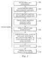
- FIG. 2is flowchart of a method of implementing a system for mapping the location of devices in a data center in accordance with one embodiment.
- FIG. 1is a block diagram of an exemplary data center 100 in which a system for mapping the location of data center devices in accordance with one embodiment may be advantageously implemented.
- data centeris defined to include any set of computers and related devices, one or more of which may be interconnected directly or via one or more networks and may be supported on shelves, racks, or other appropriate support apparatuses.
- the data center 100includes a plurality of devices 102 A- 102 E, which may comprise computers and/or other electronic devices. Although not shown, it is understood that the devices 102 A- 102 E may be interconnected via a single network or subsets of the devices may be interconnected by different networks.
- the data center 100also includes various In one embodiment, each of the devices 102 A- 102 E has affixed thereto a unique visual identifier 106 A- 106 E, such as, for example, a barcode, for purposes that will be described in greater detail below.
- a unique visual identifier 106 A- 106 Esuch as, for example, a barcode, for purposes that will be described in greater detail below.
- One or more of the devices 102 A- 102 Emay be supported on or positioned near support apparatuses 107 A, 107 B, each of which also has affixed thereto a unique visual identifier 108 A, 108 B.
- the data center 100includes one or more high-resolution digital still or video cameras, represented in FIG. 1 by digital video cameras 109 A and 109 B.
- all of the visual identifiers within the data center 100including the visual identifiers 106 A- 106 E and 108 A, 108 B as well as visual identifiers affixed to other elements (such as pillars) disposed throughout the data center (not shown) to serve as reference points, must be visible to at least one of the digital cameras 109 A, 109 B.
- visibility of a visual identifier to a camerais indicated by a dashed line between the two elements.
- Image data from the digital cameras 109 A, 109 Bis transmitted to an image processing system 110 , which may be located on- or off-site from the data center 100 , via an appropriate connection.
- the image datais processed by the system 110 as will be described in detail with reference to FIG. 2 .
- the processed image datais stored in a central database 114 , which is accessible via one or more network connections (not shown). It will be recognized that, in other embodiments, the database 114 may be replaced with any other appropriate mass storage medium, such as a file system or network attached storage, for example.
- FIG. 2is a flowchart of a method for implementing a system for mapping the location of data center devices in accordance with one embodiment.
- the system 110receives image data from a source, such as the digital cameras 109 A ( FIG. 1 ).
- the image datais processed to identify the visual identifiers therein.
- each visual identifier and the coordinates of the visual identifier within the imageare extracted.
- visual identifiers that are associated with reference pointse.g., racks, shelves, pillars, etc.
- reference pointse.g., racks, shelves, pillars, etc.
- a “group”refers to a set of devices that are similar in some manner.
- a groupmay refer to a set of devices that are similarly oriented with respect to a spatial reference point or to a set of devices that are similar in some other manner (e.g., the same type of device).
- geometrycan be used to determine groups and locations of the devices in comparison to the reference points. In this manner, the devices can be lined up linearly or spatially with respect to the reference points to build the groups. At this point, each group actually comprises a single visual identifier with multiple other visual identifiers associated with it.
- each of the visual identifiersis compared with a key to determine the identity of the device associated with the visual identifier, as well as any additional information available for the identified device.
- Step 210could easily be performed using existing databases or server lists or could be performed using a special visual identifier key designed specifically for this purpose.
- a templateis accessed to define how the final output of device information should be organized. For example, each group could be organized horizontally, with reference points at the top and the device information disposed beneath the associated reference point, or vertically, with the reference points first, the network switch next, and then a listing of servers associated therewith. It will be recognized that the groups may be organized in any manner beneficial to the user and that this feature is not intended to limit the scope of the embodiments described herein.
- each of steps 202 - 212is performed for each image obtained by the system within a particular time frame.
- step 214all of the processing results are combined.
- redundant informationis removed so that the most comprehensive listing of groups can be achieved. For example, custom logic may be employed to ignore data graphs from certain images due to the angle of the image.
- the groups developed in step 208are taken, and the visual identifiers developed in step 210 are used and then the template identified in step 212 is applied.
- This step 214is performed for all of the data and the final output is built therefrom.
- the final outputcan be displayed in any electronic form, including a graphic, report, html, or pdf document.
- Each visual identifieris able to provide a location in the overall setup and provide a total picture of the data center. Additionally, a total inventory of all machines that are labeled and installed within the data center is enabled by the embodiments described herein.
Landscapes
- Engineering & Computer Science (AREA)
- Business, Economics & Management (AREA)
- Physics & Mathematics (AREA)
- Theoretical Computer Science (AREA)
- General Physics & Mathematics (AREA)
- Economics (AREA)
- Finance (AREA)
- Marketing (AREA)
- Educational Technology (AREA)
- Accounting & Taxation (AREA)
- Mathematical Physics (AREA)
- Development Economics (AREA)
- Computer Vision & Pattern Recognition (AREA)
- Entrepreneurship & Innovation (AREA)
- Human Resources & Organizations (AREA)
- Educational Administration (AREA)
- Operations Research (AREA)
- Quality & Reliability (AREA)
- Strategic Management (AREA)
- Tourism & Hospitality (AREA)
- General Business, Economics & Management (AREA)
- Image Analysis (AREA)
- Processing Or Creating Images (AREA)
Abstract
Description
Claims (20)
Priority Applications (1)
| Application Number | Priority Date | Filing Date | Title |
|---|---|---|---|
| US12/171,078US8107736B2 (en) | 2008-07-10 | 2008-07-10 | System and method for device mapping based on images and reference points |
Applications Claiming Priority (1)
| Application Number | Priority Date | Filing Date | Title |
|---|---|---|---|
| US12/171,078US8107736B2 (en) | 2008-07-10 | 2008-07-10 | System and method for device mapping based on images and reference points |
Publications (2)
| Publication Number | Publication Date |
|---|---|
| US20100008584A1 US20100008584A1 (en) | 2010-01-14 |
| US8107736B2true US8107736B2 (en) | 2012-01-31 |
Family
ID=41505226
Family Applications (1)
| Application Number | Title | Priority Date | Filing Date |
|---|---|---|---|
| US12/171,078Active2030-11-30US8107736B2 (en) | 2008-07-10 | 2008-07-10 | System and method for device mapping based on images and reference points |
Country Status (1)
| Country | Link |
|---|---|
| US (1) | US8107736B2 (en) |
Cited By (19)
| Publication number | Priority date | Publication date | Assignee | Title |
|---|---|---|---|---|
| US8622284B1 (en)* | 2010-12-22 | 2014-01-07 | Amazon Technologies, Inc. | Determining and recording the locations of objects |
| US8845110B1 (en) | 2010-12-23 | 2014-09-30 | Rawles Llc | Powered augmented reality projection accessory display device |
| US8845107B1 (en) | 2010-12-23 | 2014-09-30 | Rawles Llc | Characterization of a scene with structured light |
| US8905551B1 (en) | 2010-12-23 | 2014-12-09 | Rawles Llc | Unpowered augmented reality projection accessory display device |
| US9111326B1 (en) | 2010-12-21 | 2015-08-18 | Rawles Llc | Designation of zones of interest within an augmented reality environment |
| US9118782B1 (en) | 2011-09-19 | 2015-08-25 | Amazon Technologies, Inc. | Optical interference mitigation |
| US9134593B1 (en) | 2010-12-23 | 2015-09-15 | Amazon Technologies, Inc. | Generation and modulation of non-visible structured light for augmented reality projection system |
| US9508194B1 (en) | 2010-12-30 | 2016-11-29 | Amazon Technologies, Inc. | Utilizing content output devices in an augmented reality environment |
| US9607315B1 (en)* | 2010-12-30 | 2017-03-28 | Amazon Technologies, Inc. | Complementing operation of display devices in an augmented reality environment |
| US9721386B1 (en) | 2010-12-27 | 2017-08-01 | Amazon Technologies, Inc. | Integrated augmented reality environment |
| US20190073502A1 (en)* | 2016-09-07 | 2019-03-07 | Konica Minolta, Inc. | Management system, management apparatus, management method, and management program |
| US10838677B1 (en)* | 2016-03-28 | 2020-11-17 | Amazon Technologies, Inc. | Device-layout determinations |
| US10997552B2 (en) | 2017-03-15 | 2021-05-04 | Walmart Apollo, Llc | System and method for determination and management of root cause for inventory problems |
| US11055662B2 (en) | 2017-03-15 | 2021-07-06 | Walmart Apollo, Llc | System and method for perpetual inventory management |
| US11282157B2 (en)* | 2017-03-15 | 2022-03-22 | Walmart Apollo, Llc | System and method for management of product movement |
| US11449828B2 (en) | 2017-05-26 | 2022-09-20 | Walmart Apollo, Llc | System and method for management of perpetual inventory values based upon confidence level |
| US11715066B2 (en) | 2017-03-15 | 2023-08-01 | Walmart Apollo, Llc | System and method for management of perpetual inventory values based upon customer product purchases |
| US11816628B2 (en) | 2017-03-15 | 2023-11-14 | Walmart Apollo, Llc | System and method for management of perpetual inventory values associated with nil picks |
| US11868960B2 (en) | 2017-03-15 | 2024-01-09 | Walmart Apollo, Llc | System and method for perpetual inventory management |
Families Citing this family (4)
| Publication number | Priority date | Publication date | Assignee | Title |
|---|---|---|---|---|
| JP5783885B2 (en)* | 2011-11-11 | 2015-09-24 | 株式会社東芝 | Information presentation apparatus, method and program thereof |
| US20140351408A1 (en)* | 2013-05-21 | 2014-11-27 | International Business Machines Corporation | Utilizing augmented reality for locating computer hardware associated to a reported incident |
| US9324000B2 (en)* | 2014-07-25 | 2016-04-26 | Ca, Inc. | Identifying objects in an image using coded reference identifiers |
| CN111833253B (en)* | 2020-07-20 | 2024-01-19 | 北京百度网讯科技有限公司 | Point-of-interest space topology construction method and device, computer system and medium |
Citations (1)
| Publication number | Priority date | Publication date | Assignee | Title |
|---|---|---|---|---|
| US7693757B2 (en)* | 2006-09-21 | 2010-04-06 | International Business Machines Corporation | System and method for performing inventory using a mobile inventory robot |
- 2008
- 2008-07-10USUS12/171,078patent/US8107736B2/enactiveActive
Patent Citations (1)
| Publication number | Priority date | Publication date | Assignee | Title |
|---|---|---|---|---|
| US7693757B2 (en)* | 2006-09-21 | 2010-04-06 | International Business Machines Corporation | System and method for performing inventory using a mobile inventory robot |
Cited By (30)
| Publication number | Priority date | Publication date | Assignee | Title |
|---|---|---|---|---|
| US9111326B1 (en) | 2010-12-21 | 2015-08-18 | Rawles Llc | Designation of zones of interest within an augmented reality environment |
| US8622284B1 (en)* | 2010-12-22 | 2014-01-07 | Amazon Technologies, Inc. | Determining and recording the locations of objects |
| US9134593B1 (en) | 2010-12-23 | 2015-09-15 | Amazon Technologies, Inc. | Generation and modulation of non-visible structured light for augmented reality projection system |
| US8905551B1 (en) | 2010-12-23 | 2014-12-09 | Rawles Llc | Unpowered augmented reality projection accessory display device |
| US8845107B1 (en) | 2010-12-23 | 2014-09-30 | Rawles Llc | Characterization of a scene with structured light |
| US9236000B1 (en) | 2010-12-23 | 2016-01-12 | Amazon Technologies, Inc. | Unpowered augmented reality projection accessory display device |
| US9383831B1 (en) | 2010-12-23 | 2016-07-05 | Amazon Technologies, Inc. | Powered augmented reality projection accessory display device |
| US9766057B1 (en) | 2010-12-23 | 2017-09-19 | Amazon Technologies, Inc. | Characterization of a scene with structured light |
| US10031335B1 (en) | 2010-12-23 | 2018-07-24 | Amazon Technologies, Inc. | Unpowered augmented reality projection accessory display device |
| US8845110B1 (en) | 2010-12-23 | 2014-09-30 | Rawles Llc | Powered augmented reality projection accessory display device |
| US9721386B1 (en) | 2010-12-27 | 2017-08-01 | Amazon Technologies, Inc. | Integrated augmented reality environment |
| US9508194B1 (en) | 2010-12-30 | 2016-11-29 | Amazon Technologies, Inc. | Utilizing content output devices in an augmented reality environment |
| US9607315B1 (en)* | 2010-12-30 | 2017-03-28 | Amazon Technologies, Inc. | Complementing operation of display devices in an augmented reality environment |
| US9118782B1 (en) | 2011-09-19 | 2015-08-25 | Amazon Technologies, Inc. | Optical interference mitigation |
| US10838677B1 (en)* | 2016-03-28 | 2020-11-17 | Amazon Technologies, Inc. | Device-layout determinations |
| US20190073502A1 (en)* | 2016-09-07 | 2019-03-07 | Konica Minolta, Inc. | Management system, management apparatus, management method, and management program |
| US10643043B2 (en)* | 2016-09-07 | 2020-05-05 | Konica Minolta, Inc. | Management system, management apparatus, management method, and management program |
| US11715066B2 (en) | 2017-03-15 | 2023-08-01 | Walmart Apollo, Llc | System and method for management of perpetual inventory values based upon customer product purchases |
| US11055662B2 (en) | 2017-03-15 | 2021-07-06 | Walmart Apollo, Llc | System and method for perpetual inventory management |
| US11282157B2 (en)* | 2017-03-15 | 2022-03-22 | Walmart Apollo, Llc | System and method for management of product movement |
| US11501251B2 (en) | 2017-03-15 | 2022-11-15 | Walmart Apollo, Llc | System and method for determination and management of root cause for inventory problems |
| US10997552B2 (en) | 2017-03-15 | 2021-05-04 | Walmart Apollo, Llc | System and method for determination and management of root cause for inventory problems |
| US11797929B2 (en) | 2017-03-15 | 2023-10-24 | Walmart Apollo, Llc | System and method for perpetual inventory management |
| US11816628B2 (en) | 2017-03-15 | 2023-11-14 | Walmart Apollo, Llc | System and method for management of perpetual inventory values associated with nil picks |
| US11868960B2 (en) | 2017-03-15 | 2024-01-09 | Walmart Apollo, Llc | System and method for perpetual inventory management |
| US12190290B2 (en) | 2017-03-15 | 2025-01-07 | Walmart Apollo, Llc | System and method for management of perpetual inventory values based upon customer product purchases |
| US12271864B2 (en) | 2017-03-15 | 2025-04-08 | Walmart Apollo, Llc | System and method for management of perpetual inventory values associated with nil picks |
| US12307421B2 (en) | 2017-03-15 | 2025-05-20 | Walmart Apollo, Llc | System and method for perpetual inventory management |
| US12333492B2 (en) | 2017-03-15 | 2025-06-17 | Walmart Apollo, Llc | System and method for perpetual inventory management |
| US11449828B2 (en) | 2017-05-26 | 2022-09-20 | Walmart Apollo, Llc | System and method for management of perpetual inventory values based upon confidence level |
Also Published As
| Publication number | Publication date |
|---|---|
| US20100008584A1 (en) | 2010-01-14 |
Similar Documents
| Publication | Publication Date | Title |
|---|---|---|
| US8107736B2 (en) | System and method for device mapping based on images and reference points | |
| US12412150B2 (en) | Information processing apparatus, control method, and program | |
| JP7416292B2 (en) | Information processing device, information processing system, control method, and program | |
| CN109255622B (en) | Traceable anti-fake data storage system | |
| CN109522780B (en) | Shelf information estimating device, information processing method, and terminal device | |
| US9690923B2 (en) | Method, apparatus and system for verifying terminal | |
| US20170293959A1 (en) | Information processing apparatus, shelf label management system, control method, and program | |
| CN107688664B (en) | Chart generation method and device, computer equipment and storage medium | |
| US20190236110A1 (en) | Cloud-Based Universal Tagging System | |
| CN113672692A (en) | Data processing method, data processing device, computer equipment and storage medium | |
| JP2016103134A (en) | Bar code evaluation device, bar code image creation system, bar code evaluation method, bar code image creation method, and bar code evaluation program | |
| CN109409865B (en) | Payment quota synchronous adjustment method, device, computer equipment and storage medium | |
| CN104657479A (en) | Method and system for displaying updated data on webpage | |
| CN102289479A (en) | Method, device and equipment for determining image showing mode and showing image | |
| CN112667596A (en) | Substitution representation method and device for multiple logical data type fields | |
| CN113343639A (en) | Product identification code image generation and information query method based on product identification code image | |
| CN112199922B (en) | Encoding method, apparatus, device, and computer-readable storage medium | |
| CN116226923A (en) | Data request processing method, device, equipment and storage medium | |
| CN114723400A (en) | Business authorization management method, device, equipment and storage medium | |
| CN114741582A (en) | Product specification acquisition method based on identification analysis and computer storage medium | |
| US7207484B2 (en) | System and method for stocktaking management | |
| CN113849520A (en) | Intelligent identification method and device of abnormal SQL (structured query language), electronic equipment and storage medium | |
| CN112632422A (en) | Intelligent image cutting method and device, electronic equipment and storage medium | |
| CN105389295A (en) | Data processing method and system for card personalization | |
| EP3270345A1 (en) | A system for facilitating verification and exchange of halal product related information in a geographically dispersed network of trading partners |
Legal Events
| Date | Code | Title | Description |
|---|---|---|---|
| AS | Assignment | Owner name:NOVELL, INC., UTAH Free format text:ASSIGNMENT OF ASSIGNORS INTEREST;ASSIGNORS:BROWN, JEREMY RAY;SABIN, JASON ALLEN;TIMPSON, DANIEL ROBERT;REEL/FRAME:021222/0574 Effective date:20080710 | |
| AS | Assignment | Owner name:CREDIT SUISSE AG, CAYMAN ISLANDS BRANCH, NEW YORK Free format text:GRANT OF PATENT SECURITY INTEREST;ASSIGNOR:NOVELL, INC.;REEL/FRAME:026270/0001 Effective date:20110427 | |
| AS | Assignment | Owner name:CREDIT SUISSE AG, CAYMAN ISLANDS BRANCH, NEW YORK Free format text:GRANT OF PATENT SECURITY INTEREST (SECOND LIEN);ASSIGNOR:NOVELL, INC.;REEL/FRAME:026275/0018 Effective date:20110427 | |
| FEPP | Fee payment procedure | Free format text:PAYOR NUMBER ASSIGNED (ORIGINAL EVENT CODE: ASPN); ENTITY STATUS OF PATENT OWNER: LARGE ENTITY | |
| STCF | Information on status: patent grant | Free format text:PATENTED CASE | |
| AS | Assignment | Owner name:NOVELL, INC., UTAH Free format text:RELEASE OF SECURITY IN PATENTS SECOND LIEN (RELEASES RF 026275/0018 AND 027290/0983);ASSIGNOR:CREDIT SUISSE AG, AS COLLATERAL AGENT;REEL/FRAME:028252/0154 Effective date:20120522 Owner name:NOVELL, INC., UTAH Free format text:RELEASE OF SECURITY INTEREST IN PATENTS FIRST LIEN (RELEASES RF 026270/0001 AND 027289/0727);ASSIGNOR:CREDIT SUISSE AG, AS COLLATERAL AGENT;REEL/FRAME:028252/0077 Effective date:20120522 | |
| AS | Assignment | Owner name:CREDIT SUISSE AG, AS COLLATERAL AGENT, NEW YORK Free format text:GRANT OF PATENT SECURITY INTEREST FIRST LIEN;ASSIGNOR:NOVELL, INC.;REEL/FRAME:028252/0216 Effective date:20120522 Owner name:CREDIT SUISSE AG, AS COLLATERAL AGENT, NEW YORK Free format text:GRANT OF PATENT SECURITY INTEREST SECOND LIEN;ASSIGNOR:NOVELL, INC.;REEL/FRAME:028252/0316 Effective date:20120522 | |
| AS | Assignment | Owner name:NOVELL, INC., UTAH Free format text:RELEASE OF SECURITY INTEREST RECORDED AT REEL/FRAME 028252/0316;ASSIGNOR:CREDIT SUISSE AG;REEL/FRAME:034469/0057 Effective date:20141120 Owner name:NOVELL, INC., UTAH Free format text:RELEASE OF SECURITY INTEREST RECORDED AT REEL/FRAME 028252/0216;ASSIGNOR:CREDIT SUISSE AG;REEL/FRAME:034470/0680 Effective date:20141120 | |
| AS | Assignment | Owner name:BANK OF AMERICA, N.A., CALIFORNIA Free format text:SECURITY INTEREST;ASSIGNORS:MICRO FOCUS (US), INC.;BORLAND SOFTWARE CORPORATION;ATTACHMATE CORPORATION;AND OTHERS;REEL/FRAME:035656/0251 Effective date:20141120 | |
| FPAY | Fee payment | Year of fee payment:4 | |
| AS | Assignment | Owner name:MICRO FOCUS SOFTWARE INC., DELAWARE Free format text:CHANGE OF NAME;ASSIGNOR:NOVELL, INC.;REEL/FRAME:040020/0703 Effective date:20160718 | |
| AS | Assignment | Owner name:JPMORGAN CHASE BANK, N.A., AS SUCCESSOR AGENT, NEW Free format text:NOTICE OF SUCCESSION OF AGENCY;ASSIGNOR:BANK OF AMERICA, N.A., AS PRIOR AGENT;REEL/FRAME:042388/0386 Effective date:20170501 | |
| AS | Assignment | Owner name:JPMORGAN CHASE BANK, N.A., DELAWARE Free format text:SECURITY INTEREST;ASSIGNORS:ATTACHMATE CORPORATION;BORLAND SOFTWARE CORPORATION;NETIQ CORPORATION;AND OTHERS;REEL/FRAME:044183/0718 Effective date:20170901 | |
| AS | Assignment | Owner name:JPMORGAN CHASE BANK, N.A., AS SUCCESSOR AGENT, NEW Free format text:CORRECTIVE ASSIGNMENT TO CORRECT THE TO CORRECT TYPO IN APPLICATION NUMBER 10708121 WHICH SHOULD BE 10708021 PREVIOUSLY RECORDED ON REEL 042388 FRAME 0386. ASSIGNOR(S) HEREBY CONFIRMS THE NOTICE OF SUCCESSION OF AGENCY;ASSIGNOR:BANK OF AMERICA, N.A., AS PRIOR AGENT;REEL/FRAME:048793/0832 Effective date:20170501 | |
| FEPP | Fee payment procedure | Free format text:MAINTENANCE FEE REMINDER MAILED (ORIGINAL EVENT CODE: REM.); ENTITY STATUS OF PATENT OWNER: LARGE ENTITY | |
| FEPP | Fee payment procedure | Free format text:7.5 YR SURCHARGE - LATE PMT W/IN 6 MO, LARGE ENTITY (ORIGINAL EVENT CODE: M1555); ENTITY STATUS OF PATENT OWNER: LARGE ENTITY | |
| MAFP | Maintenance fee payment | Free format text:PAYMENT OF MAINTENANCE FEE, 8TH YEAR, LARGE ENTITY (ORIGINAL EVENT CODE: M1552); ENTITY STATUS OF PATENT OWNER: LARGE ENTITY Year of fee payment:8 | |
| AS | Assignment | Owner name:NETIQ CORPORATION, WASHINGTON Free format text:RELEASE OF SECURITY INTEREST REEL/FRAME 044183/0718;ASSIGNOR:JPMORGAN CHASE BANK, N.A.;REEL/FRAME:062746/0399 Effective date:20230131 Owner name:MICRO FOCUS SOFTWARE INC. (F/K/A NOVELL, INC.), WASHINGTON Free format text:RELEASE OF SECURITY INTEREST REEL/FRAME 044183/0718;ASSIGNOR:JPMORGAN CHASE BANK, N.A.;REEL/FRAME:062746/0399 Effective date:20230131 Owner name:ATTACHMATE CORPORATION, WASHINGTON Free format text:RELEASE OF SECURITY INTEREST REEL/FRAME 044183/0718;ASSIGNOR:JPMORGAN CHASE BANK, N.A.;REEL/FRAME:062746/0399 Effective date:20230131 Owner name:SERENA SOFTWARE, INC, CALIFORNIA Free format text:RELEASE OF SECURITY INTEREST REEL/FRAME 044183/0718;ASSIGNOR:JPMORGAN CHASE BANK, N.A.;REEL/FRAME:062746/0399 Effective date:20230131 Owner name:MICRO FOCUS (US), INC., MARYLAND Free format text:RELEASE OF SECURITY INTEREST REEL/FRAME 044183/0718;ASSIGNOR:JPMORGAN CHASE BANK, N.A.;REEL/FRAME:062746/0399 Effective date:20230131 Owner name:BORLAND SOFTWARE CORPORATION, MARYLAND Free format text:RELEASE OF SECURITY INTEREST REEL/FRAME 044183/0718;ASSIGNOR:JPMORGAN CHASE BANK, N.A.;REEL/FRAME:062746/0399 Effective date:20230131 Owner name:MICRO FOCUS LLC (F/K/A ENTIT SOFTWARE LLC), CALIFORNIA Free format text:RELEASE OF SECURITY INTEREST REEL/FRAME 044183/0718;ASSIGNOR:JPMORGAN CHASE BANK, N.A.;REEL/FRAME:062746/0399 Effective date:20230131 Owner name:MICRO FOCUS SOFTWARE INC. (F/K/A NOVELL, INC.), WASHINGTON Free format text:RELEASE OF SECURITY INTEREST REEL/FRAME 035656/0251;ASSIGNOR:JPMORGAN CHASE BANK, N.A.;REEL/FRAME:062623/0009 Effective date:20230131 Owner name:MICRO FOCUS (US), INC., MARYLAND Free format text:RELEASE OF SECURITY INTEREST REEL/FRAME 035656/0251;ASSIGNOR:JPMORGAN CHASE BANK, N.A.;REEL/FRAME:062623/0009 Effective date:20230131 Owner name:NETIQ CORPORATION, WASHINGTON Free format text:RELEASE OF SECURITY INTEREST REEL/FRAME 035656/0251;ASSIGNOR:JPMORGAN CHASE BANK, N.A.;REEL/FRAME:062623/0009 Effective date:20230131 Owner name:ATTACHMATE CORPORATION, WASHINGTON Free format text:RELEASE OF SECURITY INTEREST REEL/FRAME 035656/0251;ASSIGNOR:JPMORGAN CHASE BANK, N.A.;REEL/FRAME:062623/0009 Effective date:20230131 Owner name:BORLAND SOFTWARE CORPORATION, MARYLAND Free format text:RELEASE OF SECURITY INTEREST REEL/FRAME 035656/0251;ASSIGNOR:JPMORGAN CHASE BANK, N.A.;REEL/FRAME:062623/0009 Effective date:20230131 | |
| MAFP | Maintenance fee payment | Free format text:PAYMENT OF MAINTENANCE FEE, 12TH YEAR, LARGE ENTITY (ORIGINAL EVENT CODE: M1553); ENTITY STATUS OF PATENT OWNER: LARGE ENTITY Year of fee payment:12 |