US8106829B2 - Method and system for an integrated antenna and antenna management - Google Patents
Method and system for an integrated antenna and antenna managementDownload PDFInfo
- Publication number
- US8106829B2 US8106829B2US11/954,748US95474807AUS8106829B2US 8106829 B2US8106829 B2US 8106829B2US 95474807 AUS95474807 AUS 95474807AUS 8106829 B2US8106829 B2US 8106829B2
- Authority
- US
- United States
- Prior art keywords
- integrated circuit
- antenna
- inductors
- layer integrated
- layers
- Prior art date
- Legal status (The legal status is an assumption and is not a legal conclusion. Google has not performed a legal analysis and makes no representation as to the accuracy of the status listed.)
- Active, expires
Links
- 238000000034methodMethods0.000titleclaimsabstractdescription23
- 239000003990capacitorSubstances0.000claimsabstractdescription30
- 238000003491arrayMethods0.000claimsabstractdescription13
- 230000005294ferromagnetic effectEffects0.000claimsabstractdescription6
- 239000003302ferromagnetic materialSubstances0.000claimsabstractdescription6
- 239000002902ferrimagnetic materialSubstances0.000claimsabstractdescription5
- 229910000679solderInorganic materials0.000claimsdescription14
- 238000012545processingMethods0.000claimsdescription7
- 239000002184metalSubstances0.000description13
- 230000005540biological transmissionEffects0.000description10
- 230000008878couplingEffects0.000description9
- 238000010168coupling processMethods0.000description9
- 238000005859coupling reactionMethods0.000description9
- 238000006243chemical reactionMethods0.000description8
- 238000010586diagramMethods0.000description8
- 230000004044responseEffects0.000description8
- 238000004590computer programMethods0.000description4
- 239000004593EpoxySubstances0.000description3
- 230000001413cellular effectEffects0.000description3
- 238000004891communicationMethods0.000description3
- 230000003203everyday effectEffects0.000description3
- 239000000463materialSubstances0.000description3
- 238000010295mobile communicationMethods0.000description3
- 235000009854Cucurbita moschataNutrition0.000description1
- 240000001980Cucurbita pepoSpecies0.000description1
- 235000009852Cucurbita pepoNutrition0.000description1
- 230000003321amplificationEffects0.000description1
- 238000013459approachMethods0.000description1
- 230000000740bleeding effectEffects0.000description1
- 238000005516engineering processMethods0.000description1
- 239000004744fabricSubstances0.000description1
- 230000006870functionEffects0.000description1
- 238000010348incorporationMethods0.000description1
- 230000010365information processingEffects0.000description1
- 239000011810insulating materialSubstances0.000description1
- 230000005291magnetic effectEffects0.000description1
- 238000012986modificationMethods0.000description1
- 230000004048modificationEffects0.000description1
- 238000003199nucleic acid amplification methodMethods0.000description1
- 230000008569processEffects0.000description1
- 235000020354squashNutrition0.000description1
Images


Classifications
- H—ELECTRICITY
- H01—ELECTRIC ELEMENTS
- H01Q—ANTENNAS, i.e. RADIO AERIALS
- H01Q1/00—Details of, or arrangements associated with, antennas
- H01Q1/12—Supports; Mounting means
- H01Q1/22—Supports; Mounting means by structural association with other equipment or articles
- H01Q1/2283—Supports; Mounting means by structural association with other equipment or articles mounted in or on the surface of a semiconductor substrate as a chip-type antenna or integrated with other components into an IC package
- H—ELECTRICITY
- H01—ELECTRIC ELEMENTS
- H01L—SEMICONDUCTOR DEVICES NOT COVERED BY CLASS H10
- H01L2223/00—Details relating to semiconductor or other solid state devices covered by the group H01L23/00
- H01L2223/58—Structural electrical arrangements for semiconductor devices not otherwise provided for
- H01L2223/64—Impedance arrangements
- H01L2223/66—High-frequency adaptations
- H01L2223/6661—High-frequency adaptations for passive devices
- H01L2223/6677—High-frequency adaptations for passive devices for antenna, e.g. antenna included within housing of semiconductor device
- H—ELECTRICITY
- H01—ELECTRIC ELEMENTS
- H01L—SEMICONDUCTOR DEVICES NOT COVERED BY CLASS H10
- H01L2224/00—Indexing scheme for arrangements for connecting or disconnecting semiconductor or solid-state bodies and methods related thereto as covered by H01L24/00
- H01L2224/01—Means for bonding being attached to, or being formed on, the surface to be connected, e.g. chip-to-package, die-attach, "first-level" interconnects; Manufacturing methods related thereto
- H01L2224/10—Bump connectors; Manufacturing methods related thereto
- H01L2224/15—Structure, shape, material or disposition of the bump connectors after the connecting process
- H01L2224/16—Structure, shape, material or disposition of the bump connectors after the connecting process of an individual bump connector
- H01L2224/161—Disposition
- H01L2224/16151—Disposition the bump connector connecting between a semiconductor or solid-state body and an item not being a semiconductor or solid-state body, e.g. chip-to-substrate, chip-to-passive
- H01L2224/16221—Disposition the bump connector connecting between a semiconductor or solid-state body and an item not being a semiconductor or solid-state body, e.g. chip-to-substrate, chip-to-passive the body and the item being stacked
- H01L2224/16225—Disposition the bump connector connecting between a semiconductor or solid-state body and an item not being a semiconductor or solid-state body, e.g. chip-to-substrate, chip-to-passive the body and the item being stacked the item being non-metallic, e.g. insulating substrate with or without metallisation
- H01L2224/16235—Disposition the bump connector connecting between a semiconductor or solid-state body and an item not being a semiconductor or solid-state body, e.g. chip-to-substrate, chip-to-passive the body and the item being stacked the item being non-metallic, e.g. insulating substrate with or without metallisation the bump connector connecting to a via metallisation of the item
- H—ELECTRICITY
- H01—ELECTRIC ELEMENTS
- H01L—SEMICONDUCTOR DEVICES NOT COVERED BY CLASS H10
- H01L2224/00—Indexing scheme for arrangements for connecting or disconnecting semiconductor or solid-state bodies and methods related thereto as covered by H01L24/00
- H01L2224/01—Means for bonding being attached to, or being formed on, the surface to be connected, e.g. chip-to-package, die-attach, "first-level" interconnects; Manufacturing methods related thereto
- H01L2224/26—Layer connectors, e.g. plate connectors, solder or adhesive layers; Manufacturing methods related thereto
- H01L2224/31—Structure, shape, material or disposition of the layer connectors after the connecting process
- H01L2224/32—Structure, shape, material or disposition of the layer connectors after the connecting process of an individual layer connector
- H01L2224/321—Disposition
- H01L2224/32151—Disposition the layer connector connecting between a semiconductor or solid-state body and an item not being a semiconductor or solid-state body, e.g. chip-to-substrate, chip-to-passive
- H01L2224/32221—Disposition the layer connector connecting between a semiconductor or solid-state body and an item not being a semiconductor or solid-state body, e.g. chip-to-substrate, chip-to-passive the body and the item being stacked
- H01L2224/32225—Disposition the layer connector connecting between a semiconductor or solid-state body and an item not being a semiconductor or solid-state body, e.g. chip-to-substrate, chip-to-passive the body and the item being stacked the item being non-metallic, e.g. insulating substrate with or without metallisation
- H—ELECTRICITY
- H01—ELECTRIC ELEMENTS
- H01L—SEMICONDUCTOR DEVICES NOT COVERED BY CLASS H10
- H01L2224/00—Indexing scheme for arrangements for connecting or disconnecting semiconductor or solid-state bodies and methods related thereto as covered by H01L24/00
- H01L2224/73—Means for bonding being of different types provided for in two or more of groups H01L2224/10, H01L2224/18, H01L2224/26, H01L2224/34, H01L2224/42, H01L2224/50, H01L2224/63, H01L2224/71
- H01L2224/732—Location after the connecting process
- H01L2224/73201—Location after the connecting process on the same surface
- H01L2224/73203—Bump and layer connectors
- H01L2224/73204—Bump and layer connectors the bump connector being embedded into the layer connector
- H—ELECTRICITY
- H01—ELECTRIC ELEMENTS
- H01L—SEMICONDUCTOR DEVICES NOT COVERED BY CLASS H10
- H01L2924/00—Indexing scheme for arrangements or methods for connecting or disconnecting semiconductor or solid-state bodies as covered by H01L24/00
- H01L2924/15—Details of package parts other than the semiconductor or other solid state devices to be connected
- H01L2924/151—Die mounting substrate
- H01L2924/1517—Multilayer substrate
- H01L2924/15192—Resurf arrangement of the internal vias
- H—ELECTRICITY
- H01—ELECTRIC ELEMENTS
- H01L—SEMICONDUCTOR DEVICES NOT COVERED BY CLASS H10
- H01L2924/00—Indexing scheme for arrangements or methods for connecting or disconnecting semiconductor or solid-state bodies as covered by H01L24/00
- H01L2924/15—Details of package parts other than the semiconductor or other solid state devices to be connected
- H01L2924/151—Die mounting substrate
- H01L2924/153—Connection portion
- H01L2924/1532—Connection portion the connection portion being formed on the die mounting surface of the substrate
- H01L2924/15321—Connection portion the connection portion being formed on the die mounting surface of the substrate being a ball array, e.g. BGA
- H—ELECTRICITY
- H01—ELECTRIC ELEMENTS
- H01L—SEMICONDUCTOR DEVICES NOT COVERED BY CLASS H10
- H01L2924/00—Indexing scheme for arrangements or methods for connecting or disconnecting semiconductor or solid-state bodies as covered by H01L24/00
- H01L2924/19—Details of hybrid assemblies other than the semiconductor or other solid state devices to be connected
- H01L2924/191—Disposition
- H01L2924/19101—Disposition of discrete passive components
- H01L2924/19105—Disposition of discrete passive components in a side-by-side arrangement on a common die mounting substrate
Definitions
- Certain embodiments of the inventionrelate to signal processing. More specifically, certain embodiments of the invention relate to a method and system for integrated antenna and antenna management.
- Mobile communicationshave changed the way people communicate and mobile phones have been transformed from a luxury item to an essential part of every day life.
- the use of mobile phonesis today dictated by social situations, rather than hampered by location or technology.
- voice connectionsfulfill the basic need to communicate, and mobile voice connections continue to filter even further into the fabric of every day life, the mobile Internet is the next step in the mobile communication revolution.
- the mobile Internetis poised to become a common source of everyday information, and easy, versatile mobile access to this data will be taken for granted.
- FIG. 1Ais a diagram illustrating an exemplary integrated antenna management system, in accordance with an embodiment of the invention.
- FIG. 1Bis a diagram illustrating another exemplary integrated antenna management system, in accordance with an embodiment of the invention.
- FIG. 2is a diagram illustrating a cross sectional view of a multi-layer package with integrated components for antenna management, in accordance with an embodiment of the invention.
- FIG. 3is a flow chart illustrating exemplary steps for transmitting and/or receiving signals utilizing an integrated antenna and antenna management system, in accordance with an embodiment of the invention.
- FIG. 4is a block diagram illustrating an exemplary wireless device, in accordance with an embodiment of the invention.
- one or more reactances coupled to an antenna in a hybrid circuitmay be tuned and signals may be transmitted and/or received based on the tuning.
- the hybrid circuitmay comprise an integrated circuit (IC) bonded to a multi-layer package.
- the hybrid circuitmay also be referred to as a hybridized circuit, or a hybrid or hybridized package.
- the antennamay be embedded within and/or on the multi-layer package.
- the reactancesmay be within and/or on the IC and/or the multi-layer package and signals to/from the reactances may be communicated between the IC and the multi-layer package via solder balls.
- the ICmay be bonded to or mounted to an underside of the multi-layer package.
- the reactancesmay be tuned via one or more switching elements and/or logic, circuitry, and/or code within the IC.
- the reactancesmay comprise one or more inductors and/or capacitor arrays.
- the multi-layer packagemay comprise one or more layers of ferromagnetic and/or ferrimagnetic material.
- FIG. 1Ais a diagram illustrating an exemplary integrated antenna management system, in accordance with an embodiment of the invention. Referring to FIG. 1 a there is shown a transceiver 423 , a variable capacitor 102 , a switching element 104 , variable inductors 106 a and 106 b , and antennas 421 a and 421 b.
- the transceiver 423may comprise suitable logic, circuitry, and/or code for transmitting and/or receiving RF signals.
- the transceiver 423may be as described below with respect to FIG. 4 .
- a single transceiver 423is shown, the invention is not so limited. Accordingly, a separate transmitter and receiver may be utilized without departing from the various aspects and scope of the invention.
- the variable capacitor 102may comprise, for example, a varactor or a bank of capacitors coupled via one or more switching elements. Accordingly, the capacitance of the variable capacitor may be controlled via one or more control signals from, for example, the baseband processor 429 and/or the processor 425 described with respect to FIG. 4 . In this manner, tuning the capacitor may enable tuning a frequency response of the system such that signals in a desired frequency or frequency band may be received and/or transmitted.
- the switching element 104may comprise suitable logic, circuitry, and/or code that may enable selecting between antenna 421 a and 421 b .
- antenna 421 amay be utilized for transmitting and antenna 421 b may be utilized for receiving.
- antenna 421 amay be utilized for a first frequency band and antenna 421 b may be utilized for a second frequency band.
- variable inductors 106 a and 106 bmay comprise, for example, a bank of inductors coupled via one or more switching elements. Accordingly, the inductance of the variable inductors 106 a and 106 b may be controlled via one or more control signals. In this manner, tuning the variable inductors 106 a and 106 b may enable tuning a frequency response of the system such that signals in a desired frequency or frequency band may be received and/or transmitted.
- variable capacitor 102 and the inductors 106 a and 106 bmay be adjusted to tune the frequency response of the system. In this manner, a wider range of frequencies may be transmitted and/or received than may be possible with only antennas and/or fixed components.
- antenna 421 amay be a receive antenna and antenna 421 b may be a transmit antenna.
- the switch 104may enable selecting between transmit and receive.
- time division multiplexingmay be utilized to rapidly switch between antenna 421 a and 421 b such that apparent simultaneous transmission and reception may be achieved.
- antenna 421 amay receive for a portion of a time interval and antenna 421 b may transmit for a remainder of the time interval. The time interval and the portion and the remainder may be chosen such that received signals are not missed while transmitting and transmitted signals are not interrupted while receiving.
- the antennas 421 a and 421 bmay each be designed to transmit/receive different frequency bands.
- antenna 421 a combined with the tune range of the capacitor 102 and the inductor 106 amay cover a first lower frequency band
- antenna 421 b combined with the tune range of the capacitor 102 and the inductor 106 bmay cover a second higher frequency band.
- the switching element 104may enable selecting a frequency band.
- FIG. 1Bis a diagram illustrating an exemplary implementation of an integrated antenna management system, in accordance with an embodiment of the invention.
- a hybrid circuit 150comprising a transceiver 423 , capacitor arrays 152 a and 152 b , inductors L 1 , . . . , L 6 , switching elements 154 a and 154 b , and antennas 421 a and 421 b.
- the transceiver 423may comprise suitable logic, circuitry, and/or code for transmitting and/or receiving RF signals. In this regard, the transceiver 423 may be as described below with respect to FIG. 4 .
- the inductors L 1 , . . . , L 6may be fixed or variable value inductors fabricated in an multi-layer integrated circuit (IC) package.
- the multi-layer IC packagemay be as described below with respect to FIG. 2 .
- Inductors L 1 and L 2may be chosen to be values suitable for transmitting and/or receiving desired frequencies via the antenna 421 a .
- the inductors L 3 and L 4may be chosen to be values suitable for transmitting and/or receiving desired frequencies via the antenna 421 b .
- the inductors L 5 and L 6may act as AC blocks such that a bias voltage on the antenna may be maintained.
- the inductors L 5 and L 6may enable, for example, bleeding off charge that may accumulate on the antennas 421 a and 421 b , the inductors, and/or nodes coupled thereto.
- the switching element 154 a and 154 bmay comprise suitable logic, circuitry, and/or code that may enable selecting an inductance coupled, respectively, to antennas 421 a and 421 b .
- a closed switchis indicated by a dashed line and an open switch is indicated by a solid line.
- the switching element 154 amay enable coupling the antenna 421 a directly to the transceiver 423 , coupling the antenna 421 a to the transceiver 423 via the inductor L 1 , or coupling the antenna 421 a to the transceiver 423 via the inductors L 1 and L 2 .
- the switching element 154 bmay enable coupling the antenna 421 b directly to the transceiver 423 , coupling the antenna 421 b to the transceiver 423 via the inductor L 3 , or coupling the antenna 421 b to the transceiver 423 via the inductors L 3 and L 4 .
- the inductancemay be varied to tune a frequency response of the hybrid circuit 150 .
- the switching elements 154 a and 154 bmay be micro-electro-mechanical (MEMS) switches and may be fabricated in the multi-layer IC package and/or in the IC.
- the switching elements 154 a and 154 bmay be active elements fabricated in an integrated circuit (“on-chip”).
- the capacitor arrays 152 a and 152 bmay each comprise, for example, bank of capacitors coupled via one or more switching elements. Accordingly, the capacitance of the capacitor arrays 152 a and 152 b may be controlled via one or more control signals. In this manner, tuning the capacitance may enable tuning a frequency response of the hybrid circuit 150 such that signals in a desired frequency or frequency band may be received and/or transmitted.
- capacitors in the arrays 152 a and 152 bmay be in the IC, in the IC package, surface mount components on the package, surface mount components on a printed circuit board (PCB), or some combination thereof.
- the capacitor arrays 152 a and 152 bmay be adjusted to tune the frequency response of the hybrid circuit 150 .
- the switching elements 154 a and 154 bmay be controlled to select the appropriate inductance. In this manner, a wider range of frequencies may be transmitted and/or received than may be possible with only antennas and/or fixed components.
- antenna 421 amay be a receive antenna and antenna 421 b may be a transmit antenna. Accordingly, transceiver 423 may be enabled to transmit and receive simultaneously.
- the antennas 421 a and 421 bmay each be designed to transmit/receive different frequency bands.
- antenna 421 a combined with the tune range of the capacitor arrays 152 a and the inductors L 1 and L 2may cover a first frequency band
- antenna 421 b combined with the tune range of the capacitor arrays 152 b and the inductors L 3 and L 4may cover a second frequency band.
- the switching elements 154 a and 154 bmay enable selecting a frequency band.
- FIG. 2is a diagram illustrating a cross sectional view of a multi-layer package with integrated components for antenna management, in accordance with an embodiment of the invention.
- a hybrid circuit 150comprising an integrated circuit (IC) (also referred to as a “chip”) 201 and a multi-layer package 213 .
- the multi-layer package 213may comprise, an insulating material 203 , metal layers 202 , 204 , 206 , and a MEMS switch 220 .
- the multi-layer package 213may also comprise interconnect materials and, in various embodiments, one or more layers and or areas of ferromagnetic and/or ferromagnetic material.
- the IC 210may be coupled to the package 213 , and the package to a PCB (not shown), via solder balls 211 .
- One or more surface mount components 219may be mounted to the package 213 , and thermal epoxy 221 may be pressed between the IC 201 and the package 213 .
- the IC 201may comprise suitable logic, circuitry, and/or code such that the IC 201 and associated multi-layer package may be a “standardized” circuit element which may be coupled to a variety of devices (e.g., via one or more PCB traces).
- the hybrid circuit 150may comprise an input/output interface to which a device, such as the transceiver 423 , may be coupled.
- the IC 201may control one or more variable capacitances, inductances, and/or switching elements based on one or more control signals received via the input/output interface.
- the IC 201may comprise the transceiver 423 , the processor 425 , the memory 427 , and/or the baseband processor 429 described with respect to FIG. 4 .
- the IC 201may be bump-bonded or flip-chip bonded to the multi-layer package 213 utilizing the solder balls 211 .
- wire bonds connecting the IC 201 to the multi-layer package 213may be eliminated, reducing and/or eliminating uncontrollable stray inductances due to wire bonds.
- the thermal conductance out of the IC 201may be greatly improved utilizing the solder balls 211 and the thermal epoxy 221 .
- the thermal epoxy 221may be electrically insulating but thermally conductive to allow for thermal energy to be conducted out of the IC 201 to the much larger thermal mass of the multilayer package 213 .
- the solder balls 211may comprise spherical balls of metal to provide electrical, thermal and physical contact between the IC 201 and the multi-layer package 213 .
- the ICmay be pressed with enough force to squash the metal spheres somewhat, and may be performed at an elevated temperature to provide suitable electrical resistance and physical bond strength.
- the solder balls 211may also be utilized to provide electrical, thermal and physical contact between the multi-layer package 213 and a printed circuit board comprising other parts of, for example, the wireless system 420 described with respect to FIG. 4 .
- the surface mount devices 219 A and 219 Bmay comprise discrete circuit elements such as resistors, capacitors, inductors, and diodes, for example.
- the surface mount devices 219 A and 219 Bmay be soldered to the multi-layer package 213 to provide electrical contact.
- the metal layer 202may comprise a deposited metal layer utilized to delineate one or more antennas (e.g., 421 a of FIG. 1B ).
- the metal layer 202may have a shape and/or size suited for receiving desired frequencies. Although, only a single antenna is depicted in FIG. 2 , additional antennas may be fabricated in the package 213 .
- the metal layers 206 a and 206 bmay comprise deposited metal layers utilized to delineate inductors (e.g., L 1 and L 2 of FIG. 1B ).
- the metal layers 206 a and 206 bmay be spiral shaped transmission lines with a first terminal on the outer ring of the spiral and a second terminal at the center of the spiral.
- additional inductorsmay be fabricated in the package 213 .
- the various metal layersmay be interconnected and/or coupled to the solder balls 211 via metal 204 .
- metal 204may comprise one or more metal layers and/or vias.
- one or more MEMS switches 220may be realized in the multi-layer package 213 or in the IC 201 .
- the MEMS switch 220may close when, for example a magnetic field is induced on a switch terminal.
- the MEMS switches 220may each comprise a thin conductive element or film which when in the open position is suspended above a switch terminal (as indicated by the solid lines in FIG. 2 ) and when in the closed position is in contact with a switch terminal (as indicated by the dashed lines in FIG. 2 ). Accordingly, energizing the terminal, for example, may generate an attracting force that draws the element of film into contact with the terminal.
- the IC 201 and associated package 213may be utilized to transmit and/or receive RF signals.
- the IC 201may be electrically coupled to devices fabricated on and/or within the multi-layer package 213 , such as antennas, inductors, transmission lines, capacitors, surface mount devices, etc.
- signals received via the integrated antenna 202may be coupled to the IC 201 via a first solder ball and to a first terminal of the inductor 206 a .
- a second terminal of the inductor 106 amay be coupled to the IC 201 via a second solder ball and to a first terminal of the inductor 106 b .
- the second terminal of the inductor 106 bmay be coupled to the IC 201 via a third solder ball.
- logic, circuitry, and/or code in the IC 201may select whether to utilize the received signal from the first, second, or third input (solder ball). Accordingly, selecting the different inputs may correspond to different inductances through which the received signal is conveyed.
- additional devicesmay be integrated into the multi-layer package without deviating from the scope of the present invention.
- one or more circuit valuesmay be adjusted and/or tuned via the surface mount devices.
- the MEMS switch 220may enable coupling/decoupling the surface mount devices to the IC 210 .
- the surface mount devicesmay be capacitors in the capacitor arrays 152 described with respect to FIGS. 1B and 1C .
- additional MEMS switchesmay be integrated in the multi-layer package 213 and may be utilized for coupling/decoupling integrated and/or surface mount components within/on the multi-layer package to other components within/on the package 213 and/or to the IC 210 .
- switching elements in the IC 210may be utilized for coupling devices within the IC 210 , within the multi-layer package 213 , and between the multi-layer package 213 and the IC 210 .
- capacitors and switchescomprising the capacitor arrays 152 described with respect to FIGS. 1B and 1C may each be in the IC 210 and/or in the multi-layer package 213 .
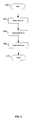
- FIG. 3is a flow chart illustrating exemplary steps for transmitting and/or receiving signals utilizing an integrated antenna and antenna management system, in accordance with an embodiment of the invention.
- the exemplary stepsmay begin with step 302 when a system is ready to begin transmitting and/or receiving RF signals. Subsequent to step 302 , the exemplary steps may advance to step 304 .
- an antennamay be selected for transmission and/or reception.
- a plurality of antennasmay be fabricated on an IC package and may be selected based on mode of transmission, mode of reception, desired frequency, etc. Accordingly, one or more switches (on-chip and/or in the IC package) may be controlled via one or more control signals.
- step 306one or more capacitances may be tuned to adjust the frequency response of the system. In this regard, the system may be tuned to a desired transmit/receive frequency.
- step 308one or more inductances may be tuned to adjust the frequency response of the system. In this regard, the system may be tuned to a desired transmit/receive frequency.
- step 310the system may begin transmitting and/or receiving via the integrated antenna(s).
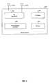
- FIG. 4is a block diagram illustrating an exemplary wireless device, in accordance with an embodiment of the invention.
- a wireless device 420may comprise an RF receiver 423 a , an RF transmitter 423 b , a digital baseband processor 429 , a processor 425 , and a memory 427 .
- a receive antenna 421 amay be communicatively coupled to the RF receiver 423 a .
- a transmit antenna 421 bmay be communicatively coupled to the RF transmitter 423 b .
- the wireless device 420may be operated in a system, such as the cellular network and/or digital video broadcast network, for example.
- the wireless device 420may comprise one or more hybrid circuits, such as the hybrid circuit described with respect to FIG. 1B .
- the RF receiver 423 amay comprise suitable logic, circuitry, and/or code that may enable processing of received RF signals.
- the RF receiver 423 amay enable receiving RF signals in a plurality of frequency bands.
- the RF receiver 423 amay enable receiving signals in extremely high frequency (e.g., 60 GHz) bands.
- the receiver 423 amay be as described with respect to FIG. 1A .
- the receiver 423 amay be enabled to receive, filter, amplify, down-convert, and/or perform analog to digital conversion.
- voltage and/or current supplied to one or more components of the receiver 423 amay be dynamically adjusted, and thus power efficiency of the receiver 423 a may be improved over conventional receivers.
- the wireless device 420may comprise a plurality of the receivers 423 a and may thus support, for example, multiple frequency bands and or simultaneous reception of multiple signals in the same frequency band.
- the RF receiver 423 amay down convert a received RF signal.
- the RF receiver 423 amay perform direct down conversion of the received RF signal to a baseband or may convert the received RF signal to an intermediate frequency (IF).
- the receiver 423 amay perform quadrature down-conversion where in-phase components and quadrature phase components may be processed in parallel.
- the digital baseband processor 429may comprise suitable logic, circuitry, and/or code that may enable processing and/or handling of baseband signals.
- the digital baseband processor 429may process or handle signals received from the RF receiver 423 a and/or signals to be transferred to the RF transmitter 423 b , when the RF transmitter 423 b is present, for transmission to the network.
- the digital baseband processor 429may also provide control and/or feedback information to the RF receiver 423 a and to the RF transmitter 423 b based on information from the processed signals.
- the baseband processor 429may provide a control signal to one or more of SSI 104 , the LNA 110 , the mixer 112 , the filter 114 (and possibly 106 and 108 ), the regulator(s) 118 , and/or the ADC 116 .
- the digital baseband processor 429may communicate information and/or data from the processed signals to the processor 425 and/or to the memory 427 .
- the digital baseband processor 429may receive information from the processor 425 and/or to the memory 427 , which may be processed and transferred to the RF transmitter 423 b for transmission to the network.
- the RF transmitter 423 bmay comprise suitable logic, circuitry, and/or code that may enable processing of RF signals for transmission.
- the RF transmitter 423 bmay enable transmission of RF signals in a plurality of frequency bands.
- the RF transmitter 423 bmay enable transmitting signals in cellular frequency bands.
- Each frequency band supported by the RF transmitter 423 bmay have a corresponding front-end circuit for handling amplification and up conversion operations, for example.
- the RF transmitter 423 bmay be referred to as a multi-band transmitter when it supports more than one frequency band.
- the wireless device 420may comprise more than one RF transmitter 423 b , wherein each of the RF transmitter 423 b may be a single-band or a multi-band transmitter.
- the RF transmitter 423 bmay perform direct up conversion of the baseband signal to an RF signal. In some instances, the RF transmitter 423 b may enable digital-to-analog conversion of the baseband signal components received from the digital baseband processor 429 before up conversion. In other instances, the RF transmitter 423 b may receive baseband signal components in analog form.
- the processor 425may comprise suitable logic, circuitry, and/or code that may enable control and/or data processing operations for the wireless device 420 .
- the processor 425may be utilized to control at least a portion of the RF receiver 423 a , the RF transmitter 423 b , the digital baseband processor 429 , and/or the memory 427 .
- the processor 425may generate at least one signal for controlling operations within the wireless device 420 .
- the baseband processor 429may provide a control signal to one or more of SSI 104 , the LNA 110 , the mixer 112 , the filter 114 (and possibly 106 and 108 ), the regulator(s) 118 , and/or the ADC 116 .
- the processor 425may also enable executing of applications that may be utilized by the wireless device 420 .
- the processor 425may execute applications that may enable displaying and/or interacting with content received via cellular transmission signals in the wireless device 420 .
- the memory 427may comprise suitable logic, circuitry, and/or code that may enable storage of data and/or other information utilized by the wireless device 420 .
- the memory 427may be utilized for storing processed data generated by the digital baseband processor 429 and/or the processor 425 .
- the memory 427may also be utilized to store information, such as configuration information, that may be utilized to control the operation of at least one block in the wireless device 420 .
- the memory 427may comprise information necessary to configure the RF receiver 423 a to enable receiving signals at various signal levels and in the presence of varying amounts of interference.
- the baseband processormay store control and/or configuration information for one or more of the SSI 104 , the LNA 110 , the mixer 112 , the filter 114 (and possibly 106 and 108 ), the regulator(s) 118 , and/or the ADC 116 .
- Exemplary aspects of a method and system for integrated antenna and antenna managementmay comprise, tuning one or more reactances coupled to an antenna (e.g., antenna 421 a or 421 b of FIG. 1B ) in a hybrid circuit (e.g., 150 of FIG. 1B ). Signals may be transmitted and/or received via the antenna based on the tuning.
- the hybrid circuitsmay comprise an integrated circuit (IC) (e.g., 201 of FIG. 2 ) bonded to a multi-layer package (e.g., 213 of FIG. 2 ).
- the antennae.g., 202 of FIG. 2
- the multi-layer packagemay be embedded within and/or on the multi-layer package.
- the reactancesmay be within and/or on the IC and/or on the multi-layer package and signals to/from the reactances may be communicated between the IC and the multi-layer package via solder balls (e.g., 211 of FIG. 2 ).
- the ICmay be bonded to or mounted to an underside of the multi-layer package.
- the reactancesmay be tuned via one or more switching elements (e.g., 220 of FIG. 2 ) and/or logic, circuitry, and/or code within the IC.
- the reactancesmay comprise one or more inductors (e.g., inductors L 1 , . . . L 4 of FIG. 1B ) and/or capacitor arrays (e.g., 152 of FIG. 1B ).
- the multi-layer packagemay comprise one or more layers of ferromagnetic and/or ferrimagnetic material.
- Another embodiment of the inventionmay provide a machine-readable storage, having stored thereon, a computer program having at least one code section executable by a machine, thereby causing the machine to perform the steps as described herein for integrated antenna and antenna management.
- the present inventionmay be realized in hardware, software, or a combination of hardware and software.
- the present inventionmay be realized in a centralized fashion in at least one computer system, or in a distributed fashion where different elements are spread across several interconnected computer systems. Any kind of computer system or other apparatus adapted for carrying out the methods described herein is suited.
- a typical combination of hardware and softwaremay be a general-purpose computer system with a computer program that, when being loaded and executed, controls the computer system such that it carries out the methods described herein.
- the present inventionmay also be embedded in a computer program product, which comprises all the features enabling the implementation of the methods described herein, and which when loaded in a computer system is able to carry out these methods.
- Computer program in the present contextmeans any expression, in any language, code or notation, of a set of instructions intended to cause a system having an information processing capability to perform a particular function either directly or after either or both of the following: a) conversion to another language, code or notation; b) reproduction in a different material form.
Landscapes
- Engineering & Computer Science (AREA)
- Microelectronics & Electronic Packaging (AREA)
- Transceivers (AREA)
Abstract
Description
Claims (21)
Priority Applications (1)
| Application Number | Priority Date | Filing Date | Title |
|---|---|---|---|
| US11/954,748US8106829B2 (en) | 2007-12-12 | 2007-12-12 | Method and system for an integrated antenna and antenna management |
Applications Claiming Priority (1)
| Application Number | Priority Date | Filing Date | Title |
|---|---|---|---|
| US11/954,748US8106829B2 (en) | 2007-12-12 | 2007-12-12 | Method and system for an integrated antenna and antenna management |
Publications (2)
| Publication Number | Publication Date |
|---|---|
| US20090153421A1 US20090153421A1 (en) | 2009-06-18 |
| US8106829B2true US8106829B2 (en) | 2012-01-31 |
Family
ID=40752507
Family Applications (1)
| Application Number | Title | Priority Date | Filing Date |
|---|---|---|---|
| US11/954,748Active2030-04-04US8106829B2 (en) | 2007-12-12 | 2007-12-12 | Method and system for an integrated antenna and antenna management |
Country Status (1)
| Country | Link |
|---|---|
| US (1) | US8106829B2 (en) |
Cited By (1)
| Publication number | Priority date | Publication date | Assignee | Title |
|---|---|---|---|---|
| US20140004804A1 (en)* | 2012-06-27 | 2014-01-02 | Seong-Youp Suh | Time-variant antenna enabled by switched capacitor array on silicon |
Families Citing this family (23)
| Publication number | Priority date | Publication date | Assignee | Title |
|---|---|---|---|---|
| US8270912B2 (en)* | 2007-12-12 | 2012-09-18 | Broadcom Corporation | Method and system for a transformer in an integrated circuit package |
| US8583197B2 (en)* | 2007-12-12 | 2013-11-12 | Broadcom Corporation | Method and system for sharing antennas for high frequency and low frequency applications |
| US8855093B2 (en)* | 2007-12-12 | 2014-10-07 | Broadcom Corporation | Method and system for chip-to-chip communications with wireline control |
| US8494030B2 (en)* | 2008-06-19 | 2013-07-23 | Broadcom Corporation | Method and system for 60 GHz wireless clock distribution |
| US7880677B2 (en)* | 2007-12-12 | 2011-02-01 | Broadcom Corporation | Method and system for a phased array antenna embedded in an integrated circuit package |
| US8160498B2 (en)* | 2007-12-12 | 2012-04-17 | Broadcom Corporation | Method and system for portable data storage with integrated 60 GHz radio |
| US7911388B2 (en)* | 2007-12-12 | 2011-03-22 | Broadcom Corporation | Method and system for configurable antenna in an integrated circuit package |
| US8064936B2 (en)* | 2008-02-28 | 2011-11-22 | Broadcom Corporation | Method and system for a multistandard proxy |
| US8072287B2 (en)* | 2008-03-27 | 2011-12-06 | Broadcom Corporation | Method and system for configurable differential or single-ended signaling in an integrated circuit |
| US8086190B2 (en)* | 2008-03-27 | 2011-12-27 | Broadcom Corporation | Method and system for reconfigurable devices for multi-frequency coexistence |
| US8198714B2 (en)* | 2008-03-28 | 2012-06-12 | Broadcom Corporation | Method and system for configuring a transformer embedded in a multi-layer integrated circuit (IC) package |
| US8116676B2 (en)* | 2008-05-07 | 2012-02-14 | Broadcom Corporation | Method and system for inter IC communications utilizing a spatial multi-link repeater |
| US20100279734A1 (en)* | 2009-04-30 | 2010-11-04 | Nokia Corporation | Multiprotocol Antenna For Wireless Systems |
| US8295788B2 (en) | 2009-06-09 | 2012-10-23 | Broadcom Corporation | Method and system for an N-phase transmitter utilizing a leaky wave antenna |
| US8588686B2 (en)* | 2009-06-09 | 2013-11-19 | Broadcom Corporation | Method and system for remote power distribution and networking for passive devices |
| US8610638B2 (en) | 2011-01-17 | 2013-12-17 | Nokia Corporation | FM transmission using a RFID/NFC coil antenna |
| US9035194B2 (en)* | 2012-10-30 | 2015-05-19 | Intel Corporation | Circuit board with integrated passive devices |
| US20140167900A1 (en) | 2012-12-14 | 2014-06-19 | Gregorio R. Murtagian | Surface-mount inductor structures for forming one or more inductors with substrate traces |
| WO2014193257A1 (en)* | 2013-05-27 | 2014-12-04 | Limited Liability Company "Radio Gigabit" | Lens antenna |
| US10109914B2 (en) | 2015-03-27 | 2018-10-23 | Intel IP Corporation | Antenna system |
| EP4027458A1 (en)* | 2021-01-06 | 2022-07-13 | InnoLux Corporation | Electronic device |
| US20220216302A1 (en)* | 2021-01-06 | 2022-07-07 | Innolux Corporation | Electronic device |
| US11949175B2 (en)* | 2021-09-25 | 2024-04-02 | Qualcomm Incorporated | Millimeter wave antenna tuner |
Citations (28)
| Publication number | Priority date | Publication date | Assignee | Title |
|---|---|---|---|---|
| US5798567A (en) | 1997-08-21 | 1998-08-25 | Hewlett-Packard Company | Ball grid array integrated circuit package which employs a flip chip integrated circuit and decoupling capacitors |
| US6060433A (en) | 1998-01-26 | 2000-05-09 | Nz Applied Technologies Corporation | Method of making a microwave device having a polycrystalline ferrite substrate |
| US6281794B1 (en)* | 1998-01-02 | 2001-08-28 | Intermec Ip Corp. | Radio frequency transponder with improved read distance |
| EP1146592A1 (en) | 1998-12-24 | 2001-10-17 | NEC Corporation | Phased array antenna and its manufacturing method |
| US20040041732A1 (en) | 2001-10-03 | 2004-03-04 | Masayoshi Aikawa | Multielement planar antenna |
| US20040150554A1 (en) | 2003-02-05 | 2004-08-05 | Stenger Peter A. | Low profile active electronically scanned antenna (AESA) for Ka-band radar systems |
| US20040201526A1 (en)* | 2003-04-11 | 2004-10-14 | Gareth Knowles | Matrix architecture switch controlled adjustable performance electromagnetic energy coupling mechanisms using digital controlled single source supply |
| US20040222506A1 (en) | 2002-10-15 | 2004-11-11 | Silicon Laboratories, Inc. | Integrated circuit package configuration incorporating shielded circuit element structure |
| US20050212642A1 (en) | 2004-03-26 | 2005-09-29 | Harris Corporation | Embedded toroidal transformers in ceramic substrates |
| US20060033671A1 (en) | 2004-08-11 | 2006-02-16 | Chan Steven S | Millimeter wave phased array systems with ring slot radiator element |
| US7038625B1 (en) | 2005-01-14 | 2006-05-02 | Harris Corporation | Array antenna including a monolithic antenna feed assembly and related methods |
| US20060152911A1 (en) | 2005-01-10 | 2006-07-13 | Ixys Corporation | Integrated packaged having magnetic components |
| US20060267717A1 (en) | 2005-05-24 | 2006-11-30 | Posamentier Joshua D | Multi-tap microelectromechanical inductor |
| US7145509B2 (en)* | 2004-02-17 | 2006-12-05 | Kyocera Corporation | Array antenna and radio communication apparatus using the same |
| US20070013051A1 (en) | 2003-08-07 | 2007-01-18 | Johann Heyan | Multichip circuit module and method for the production thereof |
| US20070139112A1 (en) | 2000-09-12 | 2007-06-21 | Bocock Ryan M | Method and apparatus for stabilizing rf power amplifiers |
| US7247932B1 (en) | 2000-05-19 | 2007-07-24 | Megica Corporation | Chip package with capacitor |
| US20070205748A1 (en) | 2006-03-01 | 2007-09-06 | Toyota Jidosha Kabushiki Kaisha | Signal transmission device |
| WO2007114620A1 (en) | 2006-04-03 | 2007-10-11 | Ace Antenna Corp. | Dual polarization broadband antenna having with single pattern |
| US20080291115A1 (en) | 2007-05-22 | 2008-11-27 | Sibeam, Inc. | Surface mountable integrated circuit packaging scheme |
| US20090156157A1 (en) | 2007-12-12 | 2009-06-18 | Ahmadreza Rofougaran | Method and system for a transformer in an integrated circuit package |
| US20090153427A1 (en) | 2007-12-12 | 2009-06-18 | Ahmadreza Rofougaran | Method and system for configurable antenna in an integrated circuit package |
| US20090153260A1 (en) | 2007-12-12 | 2009-06-18 | Ahmadreza Rofougaran | Method and system for a configurable transformer integrated on chip |
| US20090189064A1 (en) | 2005-07-26 | 2009-07-30 | Sionex Corporation | Ultra compact ion mobility based analyzer apparatus, method, and system |
| US20090243749A1 (en) | 2008-03-27 | 2009-10-01 | Ahmadreza Rofougaran | Method and system for configurable differential or single-ended signaling in an integrated circuit |
| US20090243767A1 (en) | 2008-03-28 | 2009-10-01 | Ahmadreza Rofougaran | Method and system for configuring a transformer embedded in a multi-layer integrated circuit (ic) package |
| US20090243741A1 (en) | 2008-03-27 | 2009-10-01 | Ahmadreza Rofougaran | Method and system for processing signals via an oscillator load embedded in an integrated circuit (ic) package |
| US7880677B2 (en) | 2007-12-12 | 2011-02-01 | Broadcom Corporation | Method and system for a phased array antenna embedded in an integrated circuit package |
Family Cites Families (92)
| Publication number | Priority date | Publication date | Assignee | Title |
|---|---|---|---|---|
| US5385544A (en)* | 1992-08-12 | 1995-01-31 | Vidamed, Inc. | BPH ablation method and apparatus |
| US6672151B1 (en)* | 1989-12-20 | 2004-01-06 | Sentech, Inc. | Apparatus and method for remote sensing and receiving |
| US5290283A (en)* | 1990-01-31 | 1994-03-01 | Kabushiki Kaisha Toshiba | Power supply apparatus for electrosurgical unit including electrosurgical-current waveform data storage |
| US5304917A (en)* | 1990-11-30 | 1994-04-19 | Burr-Brown Corporation | Compact low noise low power dual mode battery charging circuit |
| US5620481A (en)* | 1991-07-05 | 1997-04-15 | Desai; Jawahar M. | Device for multi-phase radio-frequency ablation |
| US6022347A (en)* | 1991-08-12 | 2000-02-08 | Karl Storz Gmbh & Co. | High-frequency surgical generator for adjusted cutting and coagulation |
| US5906614A (en)* | 1991-11-08 | 1999-05-25 | Ep Technologies, Inc. | Tissue heating and ablation systems and methods using predicted temperature for monitoring and control |
| US5891095A (en)* | 1993-05-10 | 1999-04-06 | Arthrocare Corporation | Electrosurgical treatment of tissue in electrically conductive fluid |
| US5282840A (en)* | 1992-03-26 | 1994-02-01 | Medtronic, Inc. | Multiple frequency impedance measurement system |
| US5443470A (en)* | 1992-05-01 | 1995-08-22 | Vesta Medical, Inc. | Method and apparatus for endometrial ablation |
| US5496314A (en)* | 1992-05-01 | 1996-03-05 | Hemostatic Surgery Corporation | Irrigation and shroud arrangement for electrically powered endoscopic probes |
| US5609560A (en)* | 1992-08-19 | 1997-03-11 | Olympus Optical Co., Ltd. | Medical operation device control system for controlling a operation devices accessed respectively by ID codes |
| US6059781A (en)* | 1992-10-27 | 2000-05-09 | Yamanashi; William S. | Electroconvergent cautery system |
| WO1994010922A1 (en)* | 1992-11-13 | 1994-05-26 | Ep Technologies, Inc. | Cardial ablation systems using temperature monitoring |
| US5295857A (en)* | 1992-12-23 | 1994-03-22 | Toly Elde V | Electrical connector with improved wire termination system |
| US5628771A (en)* | 1993-05-12 | 1997-05-13 | Olympus Optical Co., Ltd. | Electromagnetic-wave thermatological device |
| JP2598574Y2 (en)* | 1993-08-25 | 1999-08-16 | 矢崎総業株式会社 | Connector shielded wire connection structure |
| US5462521A (en)* | 1993-12-21 | 1995-10-31 | Angeion Corporation | Fluid cooled and perfused tip for a catheter |
| US5735846A (en)* | 1994-06-27 | 1998-04-07 | Ep Technologies, Inc. | Systems and methods for ablating body tissue using predicted maximum tissue temperature |
| DE4425195C1 (en)* | 1994-07-16 | 1995-11-16 | Osypka Peter | Heart catheter with multiple electrode device |
| US5720742A (en)* | 1994-10-11 | 1998-02-24 | Zacharias; Jaime | Controller and actuating system for surgical instrument |
| US6409722B1 (en)* | 1998-07-07 | 2002-06-25 | Medtronic, Inc. | Apparatus and method for creating, maintaining, and controlling a virtual electrode used for the ablation of tissue |
| US6039732A (en)* | 1995-04-18 | 2000-03-21 | Olympus Optical Co., Ltd. | Electric operation apparatus |
| US5743900A (en)* | 1995-06-06 | 1998-04-28 | Sun Star Technology, Inc. | Hot tip catheter and method for using the same |
| US20050004634A1 (en)* | 1995-06-07 | 2005-01-06 | Arthrocare Corporation | Methods for electrosurgical treatment of spinal tissue |
| US6837888B2 (en)* | 1995-06-07 | 2005-01-04 | Arthrocare Corporation | Electrosurgical probe with movable return electrode and methods related thereto |
| US6022346A (en)* | 1995-06-07 | 2000-02-08 | Ep Technologies, Inc. | Tissue heating and ablation systems and methods using self-heated electrodes |
| US5697925A (en)* | 1995-06-09 | 1997-12-16 | Engineering & Research Associates, Inc. | Apparatus and method for thermal ablation |
| US5868737A (en)* | 1995-06-09 | 1999-02-09 | Engineering Research & Associates, Inc. | Apparatus and method for determining ablation |
| US6228078B1 (en)* | 1995-11-22 | 2001-05-08 | Arthrocare Corporation | Methods for electrosurgical dermatological treatment |
| US6186147B1 (en)* | 1996-05-30 | 2001-02-13 | Nuvotek Limited | Method for electrosurgical tissue cutting and coagulation |
| US6544260B1 (en)* | 1996-08-20 | 2003-04-08 | Oratec Interventions, Inc. | Method for treating tissue in arthroscopic environment using precooling and apparatus for same |
| US5891142A (en)* | 1996-12-06 | 1999-04-06 | Eggers & Associates, Inc. | Electrosurgical forceps |
| US6235022B1 (en)* | 1996-12-20 | 2001-05-22 | Cardiac Pathways, Inc | RF generator and pump apparatus and system and method for cooled ablation |
| US5860832A (en)* | 1997-01-29 | 1999-01-19 | Ut Automotive Dearborn, Inc. | Method for connecting flat flexible cable and a connector |
| DE19721362B4 (en)* | 1997-04-01 | 2011-05-26 | Axel Muntermann | Device and calibration method for catheter ablation |
| US6565562B1 (en)* | 1997-06-27 | 2003-05-20 | Baylis Medical Company Inc. | Method for the radio frequency perforation and the enlargement of a body tissue |
| JP2001514921A (en)* | 1997-08-13 | 2001-09-18 | サークス, インコーポレイテッド | Non-invasive devices, methods, and systems for tissue contraction |
| US6358246B1 (en)* | 1999-06-25 | 2002-03-19 | Radiotherapeutics Corporation | Method and system for heating solid tissue |
| US6039735A (en)* | 1997-10-03 | 2000-03-21 | Megadyne Medical Products, Inc. | Electric field concentrated electrosurgical electrode |
| DE19757720A1 (en)* | 1997-12-23 | 1999-06-24 | Sulzer Osypka Gmbh | Method for operating a high-frequency ablation device and device for high-frequency tissue ablation |
| US6562037B2 (en)* | 1998-02-12 | 2003-05-13 | Boris E. Paton | Bonding of soft biological tissues by passing high frequency electric current therethrough |
| US6216703B1 (en)* | 1998-05-08 | 2001-04-17 | Thermatrx, Inc. | Therapeutic prostatic thermotherapy |
| US6537272B2 (en)* | 1998-07-07 | 2003-03-25 | Medtronic, Inc. | Apparatus and method for creating, maintaining, and controlling a virtual electrode used for the ablation of tissue |
| US6183468B1 (en)* | 1998-09-10 | 2001-02-06 | Scimed Life Systems, Inc. | Systems and methods for controlling power in an electrosurgical probe |
| US6371963B1 (en)* | 1998-11-17 | 2002-04-16 | Scimed Life Systems, Inc. | Device for controlled endoscopic penetration of injection needle |
| US6696844B2 (en)* | 1999-06-04 | 2004-02-24 | Engineering & Research Associates, Inc. | Apparatus and method for real time determination of materials' electrical properties |
| US6237604B1 (en)* | 1999-09-07 | 2001-05-29 | Scimed Life Systems, Inc. | Systems and methods for preventing automatic identification of re-used single use devices |
| US20040068307A1 (en)* | 2000-02-08 | 2004-04-08 | Gyrus Medical Limited | Surgical instrument |
| US6232556B1 (en)* | 2000-02-23 | 2001-05-15 | Delphi Technologies, Inc. | Flat wire to round wire connection system |
| IT1314857B1 (en)* | 2000-07-07 | 2003-01-16 | Salvatore Rinaldi | THERAPEUTIC ASYMMETRICAL RADIOELECTRIC CONVEYOR. |
| US6546270B1 (en)* | 2000-07-07 | 2003-04-08 | Biosense, Inc. | Multi-electrode catheter, system and method |
| JP3897962B2 (en)* | 2000-07-19 | 2007-03-28 | 株式会社モリタ製作所 | Identification-type instrument body, identification-type adapter, identification-type tube, and medical device using these |
| KR100387384B1 (en)* | 2000-07-26 | 2003-06-12 | 규 호 이 | Embolic material detachment detection system and method and assembly for embolic treatments |
| DK176207B1 (en)* | 2000-09-28 | 2007-02-05 | Xo Care As | Electrosurgical apparatus |
| US7008421B2 (en)* | 2002-08-21 | 2006-03-07 | Resect Medical, Inc. | Apparatus and method for tissue resection |
| EP1287788B1 (en)* | 2001-08-27 | 2011-04-20 | Gyrus Medical Limited | Electrosurgical system |
| US7344532B2 (en)* | 2001-08-27 | 2008-03-18 | Gyrus Medical Limited | Electrosurgical generator and system |
| US6966907B2 (en)* | 2001-08-27 | 2005-11-22 | Gyrus Medical Limited | Electrosurgical generator and system |
| US6652514B2 (en)* | 2001-09-13 | 2003-11-25 | Alan G. Ellman | Intelligent selection system for electrosurgical instrument |
| NL1019206C2 (en)* | 2001-10-22 | 2003-04-23 | Johannes Josephus Maria Cuppen | Device and method for electromagnetic therapy. |
| US6827715B2 (en)* | 2002-01-25 | 2004-12-07 | Medtronic, Inc. | System and method of performing an electrosurgical procedure |
| US7192427B2 (en)* | 2002-02-19 | 2007-03-20 | Afx, Inc. | Apparatus and method for assessing transmurality of a tissue ablation |
| US7163536B2 (en)* | 2004-06-10 | 2007-01-16 | Baylis Medical Company Inc. | Determining connections of multiple energy sources and energy delivery devices |
| US6695837B2 (en)* | 2002-03-13 | 2004-02-24 | Starion Instruments Corporation | Power supply for identification and control of electrical surgical tools |
| US20040030330A1 (en)* | 2002-04-18 | 2004-02-12 | Brassell James L. | Electrosurgery systems |
| US7008417B2 (en)* | 2002-04-22 | 2006-03-07 | Medtronics, Inc. | Detecting coagulum formation |
| US6730078B2 (en)* | 2002-04-22 | 2004-05-04 | Cardiac Pacemakers, Inc. | RF ablation apparatus and method using multi-frequency energy delivery |
| DE10218894A1 (en)* | 2002-04-26 | 2003-11-13 | Storz Endoskop Prod Gmbh | Device for monitoring medical devices |
| US20040010554A1 (en)* | 2002-07-15 | 2004-01-15 | Hall John M. | Determining a destination e-mail address for sending scanned documents |
| US6730079B2 (en)* | 2002-07-22 | 2004-05-04 | Medtronic Vidamed, Inc. | Method for calculating impedance and apparatus utilizing same |
| US7223264B2 (en)* | 2002-08-21 | 2007-05-29 | Resect Medical, Inc. | Thermal coagulation of tissue during tissue resection |
| US7341586B2 (en)* | 2002-08-21 | 2008-03-11 | Resect Medical, Inc. | Thermal coagulation of tissue during tissue resection |
| JP3614837B2 (en)* | 2002-08-30 | 2005-01-26 | Smk株式会社 | Wire connection plug |
| JP4004040B2 (en)* | 2002-09-05 | 2007-11-07 | 株式会社東芝 | Semiconductor device |
| US7195627B2 (en)* | 2003-01-09 | 2007-03-27 | Gyrus Medical Limited | Electrosurgical generator |
| US7357800B2 (en)* | 2003-02-14 | 2008-04-15 | Boston Scientific Scimed, Inc. | Power supply and control apparatus and electrophysiology systems including the same |
| JP5137230B2 (en)* | 2003-05-15 | 2013-02-06 | コヴィディエン・アクチェンゲゼルシャフト | Tissue sealer with non-conductive variable stop member and method for sealing tissue |
| US7156846B2 (en)* | 2003-06-13 | 2007-01-02 | Sherwood Services Ag | Vessel sealer and divider for use with small trocars and cannulas |
| JP2005058616A (en)* | 2003-08-19 | 2005-03-10 | Olympus Corp | Control device for medical system and method of control for medical system |
| JP2005102750A (en)* | 2003-09-26 | 2005-04-21 | Olympus Corp | Electrosurgical power supply apparatus |
| CA2543613A1 (en)* | 2003-10-28 | 2005-05-12 | Uab Research Foundation | Electrosurgical control system |
| US20050109111A1 (en)* | 2003-10-30 | 2005-05-26 | Delphi Technologies, Inc. | Sensor and method of transmitting sensor data |
| US6958064B2 (en)* | 2003-11-14 | 2005-10-25 | Boston Scientific Scimed, Inc. | Systems and methods for performing simultaneous ablation |
| US7156844B2 (en)* | 2003-11-20 | 2007-01-02 | Sherwood Services Ag | Electrosurgical pencil with improved controls |
| US7317955B2 (en)* | 2003-12-12 | 2008-01-08 | Conmed Corporation | Virtual operating room integration |
| US7317954B2 (en)* | 2003-12-12 | 2008-01-08 | Conmed Corporation | Virtual control of electrosurgical generator functions |
| US7525398B2 (en)* | 2005-10-18 | 2009-04-28 | Avago Technologies General Ip (Singapore) Pte. Ltd. | Acoustically communicating data signals across an electrical isolation barrier |
| US7513896B2 (en)* | 2006-01-24 | 2009-04-07 | Covidien Ag | Dual synchro-resonant electrosurgical apparatus with bi-directional magnetic coupling |
| US8152800B2 (en)* | 2007-07-30 | 2012-04-10 | Vivant Medical, Inc. | Electrosurgical systems and printed circuit boards for use therewith |
| US8216220B2 (en)* | 2007-09-07 | 2012-07-10 | Tyco Healthcare Group Lp | System and method for transmission of combined data stream |
| US8512332B2 (en)* | 2007-09-21 | 2013-08-20 | Covidien Lp | Real-time arc control in electrosurgical generators |
- 2007
- 2007-12-12USUS11/954,748patent/US8106829B2/enactiveActive
Patent Citations (29)
| Publication number | Priority date | Publication date | Assignee | Title |
|---|---|---|---|---|
| US5798567A (en) | 1997-08-21 | 1998-08-25 | Hewlett-Packard Company | Ball grid array integrated circuit package which employs a flip chip integrated circuit and decoupling capacitors |
| US6281794B1 (en)* | 1998-01-02 | 2001-08-28 | Intermec Ip Corp. | Radio frequency transponder with improved read distance |
| US6060433A (en) | 1998-01-26 | 2000-05-09 | Nz Applied Technologies Corporation | Method of making a microwave device having a polycrystalline ferrite substrate |
| EP1146592A1 (en) | 1998-12-24 | 2001-10-17 | NEC Corporation | Phased array antenna and its manufacturing method |
| US7247932B1 (en) | 2000-05-19 | 2007-07-24 | Megica Corporation | Chip package with capacitor |
| US20070139112A1 (en) | 2000-09-12 | 2007-06-21 | Bocock Ryan M | Method and apparatus for stabilizing rf power amplifiers |
| US20040041732A1 (en) | 2001-10-03 | 2004-03-04 | Masayoshi Aikawa | Multielement planar antenna |
| US20040222506A1 (en) | 2002-10-15 | 2004-11-11 | Silicon Laboratories, Inc. | Integrated circuit package configuration incorporating shielded circuit element structure |
| US20040150554A1 (en) | 2003-02-05 | 2004-08-05 | Stenger Peter A. | Low profile active electronically scanned antenna (AESA) for Ka-band radar systems |
| US20040201526A1 (en)* | 2003-04-11 | 2004-10-14 | Gareth Knowles | Matrix architecture switch controlled adjustable performance electromagnetic energy coupling mechanisms using digital controlled single source supply |
| US20070013051A1 (en) | 2003-08-07 | 2007-01-18 | Johann Heyan | Multichip circuit module and method for the production thereof |
| US7145509B2 (en)* | 2004-02-17 | 2006-12-05 | Kyocera Corporation | Array antenna and radio communication apparatus using the same |
| US20050212642A1 (en) | 2004-03-26 | 2005-09-29 | Harris Corporation | Embedded toroidal transformers in ceramic substrates |
| US20060033671A1 (en) | 2004-08-11 | 2006-02-16 | Chan Steven S | Millimeter wave phased array systems with ring slot radiator element |
| US20060152911A1 (en) | 2005-01-10 | 2006-07-13 | Ixys Corporation | Integrated packaged having magnetic components |
| US7038625B1 (en) | 2005-01-14 | 2006-05-02 | Harris Corporation | Array antenna including a monolithic antenna feed assembly and related methods |
| US20060267717A1 (en) | 2005-05-24 | 2006-11-30 | Posamentier Joshua D | Multi-tap microelectromechanical inductor |
| US20090189064A1 (en) | 2005-07-26 | 2009-07-30 | Sionex Corporation | Ultra compact ion mobility based analyzer apparatus, method, and system |
| US20070205748A1 (en) | 2006-03-01 | 2007-09-06 | Toyota Jidosha Kabushiki Kaisha | Signal transmission device |
| US20090179814A1 (en) | 2006-04-03 | 2009-07-16 | Ace Antenna Corp. | Dual polarization broadband antenna having with single pattern |
| WO2007114620A1 (en) | 2006-04-03 | 2007-10-11 | Ace Antenna Corp. | Dual polarization broadband antenna having with single pattern |
| US20080291115A1 (en) | 2007-05-22 | 2008-11-27 | Sibeam, Inc. | Surface mountable integrated circuit packaging scheme |
| US20090156157A1 (en) | 2007-12-12 | 2009-06-18 | Ahmadreza Rofougaran | Method and system for a transformer in an integrated circuit package |
| US20090153427A1 (en) | 2007-12-12 | 2009-06-18 | Ahmadreza Rofougaran | Method and system for configurable antenna in an integrated circuit package |
| US20090153260A1 (en) | 2007-12-12 | 2009-06-18 | Ahmadreza Rofougaran | Method and system for a configurable transformer integrated on chip |
| US7880677B2 (en) | 2007-12-12 | 2011-02-01 | Broadcom Corporation | Method and system for a phased array antenna embedded in an integrated circuit package |
| US20090243749A1 (en) | 2008-03-27 | 2009-10-01 | Ahmadreza Rofougaran | Method and system for configurable differential or single-ended signaling in an integrated circuit |
| US20090243741A1 (en) | 2008-03-27 | 2009-10-01 | Ahmadreza Rofougaran | Method and system for processing signals via an oscillator load embedded in an integrated circuit (ic) package |
| US20090243767A1 (en) | 2008-03-28 | 2009-10-01 | Ahmadreza Rofougaran | Method and system for configuring a transformer embedded in a multi-layer integrated circuit (ic) package |
Cited By (2)
| Publication number | Priority date | Publication date | Assignee | Title |
|---|---|---|---|---|
| US20140004804A1 (en)* | 2012-06-27 | 2014-01-02 | Seong-Youp Suh | Time-variant antenna enabled by switched capacitor array on silicon |
| US8824982B2 (en)* | 2012-06-27 | 2014-09-02 | Intel Corporation | Time-variant antenna enabled by switched capacitor array on silicon |
Also Published As
| Publication number | Publication date |
|---|---|
| US20090153421A1 (en) | 2009-06-18 |
Similar Documents
| Publication | Publication Date | Title |
|---|---|---|
| US8106829B2 (en) | Method and system for an integrated antenna and antenna management | |
| US8174451B2 (en) | Method and system for configurable antenna in an integrated circuit package | |
| US8855581B2 (en) | Integrated circuit package with transformer | |
| US7880677B2 (en) | Method and system for a phased array antenna embedded in an integrated circuit package | |
| US8319578B2 (en) | Method and system for configurable differential or single-ended signaling in an integrated circuit | |
| US8912639B2 (en) | IC package with embedded transformer | |
| US8405568B2 (en) | Wireless communication device antenna with tuning elements | |
| US20090153260A1 (en) | Method and system for a configurable transformer integrated on chip | |
| US8768269B2 (en) | MEMS and switched capacitors configured for increased resolution switching | |
| US8086190B2 (en) | Method and system for reconfigurable devices for multi-frequency coexistence | |
| US8242858B2 (en) | Method and system for matching networks embedded in an integrated circuit package | |
| US20090153265A1 (en) | Method and system for controlling mems switches in an integrated circuit package | |
| HK1138121B (en) | A method and system for transformer in ic package | |
| HK1138106B (en) | Method and system for signal processing |
Legal Events
| Date | Code | Title | Description |
|---|---|---|---|
| AS | Assignment | Owner name:BROADCOM CORPORATION, CALIFORNIA Free format text:ASSIGNMENT OF ASSIGNORS INTEREST;ASSIGNORS:ROFOUGARAN, AHMADREZA;ROFOUGARAN, MARYAM;REEL/FRAME:020491/0934 Effective date:20071210 | |
| FEPP | Fee payment procedure | Free format text:PAYOR NUMBER ASSIGNED (ORIGINAL EVENT CODE: ASPN); ENTITY STATUS OF PATENT OWNER: LARGE ENTITY | |
| STCF | Information on status: patent grant | Free format text:PATENTED CASE | |
| FPAY | Fee payment | Year of fee payment:4 | |
| AS | Assignment | Owner name:BANK OF AMERICA, N.A., AS COLLATERAL AGENT, NORTH CAROLINA Free format text:PATENT SECURITY AGREEMENT;ASSIGNOR:BROADCOM CORPORATION;REEL/FRAME:037806/0001 Effective date:20160201 Owner name:BANK OF AMERICA, N.A., AS COLLATERAL AGENT, NORTH Free format text:PATENT SECURITY AGREEMENT;ASSIGNOR:BROADCOM CORPORATION;REEL/FRAME:037806/0001 Effective date:20160201 | |
| AS | Assignment | Owner name:AVAGO TECHNOLOGIES GENERAL IP (SINGAPORE) PTE. LTD., SINGAPORE Free format text:ASSIGNMENT OF ASSIGNORS INTEREST;ASSIGNOR:BROADCOM CORPORATION;REEL/FRAME:041706/0001 Effective date:20170120 Owner name:AVAGO TECHNOLOGIES GENERAL IP (SINGAPORE) PTE. LTD Free format text:ASSIGNMENT OF ASSIGNORS INTEREST;ASSIGNOR:BROADCOM CORPORATION;REEL/FRAME:041706/0001 Effective date:20170120 | |
| AS | Assignment | Owner name:BROADCOM CORPORATION, CALIFORNIA Free format text:TERMINATION AND RELEASE OF SECURITY INTEREST IN PATENTS;ASSIGNOR:BANK OF AMERICA, N.A., AS COLLATERAL AGENT;REEL/FRAME:041712/0001 Effective date:20170119 | |
| AS | Assignment | Owner name:AVAGO TECHNOLOGIES INTERNATIONAL SALES PTE. LIMITE Free format text:MERGER;ASSIGNOR:AVAGO TECHNOLOGIES GENERAL IP (SINGAPORE) PTE. LTD.;REEL/FRAME:047230/0133 Effective date:20180509 | |
| AS | Assignment | Owner name:AVAGO TECHNOLOGIES INTERNATIONAL SALES PTE. LIMITE Free format text:CORRECTIVE ASSIGNMENT TO CORRECT THE EFFECTIVE DATE OF MERGER TO 09/05/2018 PREVIOUSLY RECORDED AT REEL: 047230 FRAME: 0133. ASSIGNOR(S) HEREBY CONFIRMS THE MERGER;ASSIGNOR:AVAGO TECHNOLOGIES GENERAL IP (SINGAPORE) PTE. LTD.;REEL/FRAME:047630/0456 Effective date:20180905 | |
| MAFP | Maintenance fee payment | Free format text:PAYMENT OF MAINTENANCE FEE, 8TH YEAR, LARGE ENTITY (ORIGINAL EVENT CODE: M1552); ENTITY STATUS OF PATENT OWNER: LARGE ENTITY Year of fee payment:8 | |
| MAFP | Maintenance fee payment | Free format text:PAYMENT OF MAINTENANCE FEE, 12TH YEAR, LARGE ENTITY (ORIGINAL EVENT CODE: M1553); ENTITY STATUS OF PATENT OWNER: LARGE ENTITY Year of fee payment:12 |