US8106787B2 - Warning system indicating excessive force on a touch screen or display - Google Patents
Warning system indicating excessive force on a touch screen or displayDownload PDFInfo
- Publication number
- US8106787B2 US8106787B2US12/291,894US29189408AUS8106787B2US 8106787 B2US8106787 B2US 8106787B2US 29189408 AUS29189408 AUS 29189408AUS 8106787 B2US8106787 B2US 8106787B2
- Authority
- US
- United States
- Prior art keywords
- touch screen
- conductive parts
- user
- signal
- implemented
- Prior art date
- Legal status (The legal status is an assumption and is not a legal conclusion. Google has not performed a legal analysis and makes no representation as to the accuracy of the status listed.)
- Expired - Fee Related, expires
Links
Images


Classifications
- G—PHYSICS
- G06—COMPUTING OR CALCULATING; COUNTING
- G06F—ELECTRIC DIGITAL DATA PROCESSING
- G06F3/00—Input arrangements for transferring data to be processed into a form capable of being handled by the computer; Output arrangements for transferring data from processing unit to output unit, e.g. interface arrangements
- G06F3/01—Input arrangements or combined input and output arrangements for interaction between user and computer
- G06F3/03—Arrangements for converting the position or the displacement of a member into a coded form
- G06F3/041—Digitisers, e.g. for touch screens or touch pads, characterised by the transducing means
- G06F3/042—Digitisers, e.g. for touch screens or touch pads, characterised by the transducing means by opto-electronic means
- G—PHYSICS
- G06—COMPUTING OR CALCULATING; COUNTING
- G06F—ELECTRIC DIGITAL DATA PROCESSING
- G06F3/00—Input arrangements for transferring data to be processed into a form capable of being handled by the computer; Output arrangements for transferring data from processing unit to output unit, e.g. interface arrangements
- G06F3/01—Input arrangements or combined input and output arrangements for interaction between user and computer
- G06F3/03—Arrangements for converting the position or the displacement of a member into a coded form
- G06F3/041—Digitisers, e.g. for touch screens or touch pads, characterised by the transducing means
- G06F3/045—Digitisers, e.g. for touch screens or touch pads, characterised by the transducing means using resistive elements, e.g. a single continuous surface or two parallel surfaces put in contact
Definitions
- the exemplary and non-limiting embodiments of this inventionrelate generally to touch screen devices and techniques to avoid inadvertent breakage of the touch screen device.
- a touch screenmay include a display which can detect the presence and location of a touch within a display area.
- a touchis often thought of either as a force by hand or stylus pen.
- the implementation of a touch screencan be done in a number of ways including, but not limited to, the use of capacitive, resistive, and optical technology.
- touch screen display devicesa user controls the operation of the device via the user's own touch.
- touch screen functionsthe users only method to operate the device is through touch. It can then be seen how the user's ability to navigate the touch screen display and apply proper amounts of force is of importance to the sustainability of the device.
- a problemcan arise due to the user being unaware of potentially applying an excessive amount of force on the touch screen/display panel.
- a first embodiment of the inventionis a method comprising: receiving a signal generated by a touch screen device in response to a tactile input from a user on an input surface of the touch screen device; and in response, presenting information to a user, the information comprising a warning that the user is exerting an excessive amount of force on a surface of the touch screen device.
- Another embodiment of the inventionis a computer readable medium encoded with a computer program executable by a processor to perform actions comprising: receiving a signal generated by a touch screen device of the touch screen device in response to a tactile input from a user on an input surface; and in response, presenting information to a user, the information comprising a warning that the user is exerting an excessive amount of force on a surface of the touch screen device.
- Another further embodiment of the inventionis an apparatus comprising: an input surface configured to generate a signal in response to tactile input from a user; and an output configured to provide an output signal when the user is exerting an excessive amount of force on the input surface.
- FIG. 1shows a simplified block diagram of various electronic devices that are suitable for use in practicing the exemplary embodiments of this invention.
- FIG. 2shows the internal operation of a mobile device that contains a touch screen.
- FIG. 3illustrates display panel pixel cell control
- FIG. 4is a further illustration of display panel pixel cell control.
- FIG. 5is an even further illustration of display panel pixel cell control.
- FIG. 6is a still further illustration of display panel pixel cell control.
- FIG. 6Aillustrates a display panel further including a VCOM plane.
- FIGS. 6B and 6Cprovide graphs of the VCOM voltage during image frame updating as static and dynamic voltages respectively.
- FIG. 7is an illustration of two different touch screen configurations.
- FIGS. 7A and 7Bprovide illustration for a separated touch screen based on a sheet structure.
- FIGS. 7C and 7Dprovide illustration for a display integrated touch screen based on a matrix structure.
- FIG. 8is an illustration of display integrated touch screen scanning.
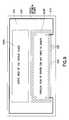
- FIG. 9is an illustration of a previous attempt to implement broken panel detection.
- FIG. 10shows the use of varying heights of conductive parts to trigger a warning.
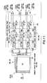
- FIG. 11shows the operation of the display panel and touch screen panel according to the device of FIG. 10 .
- FIG. 12shows the implementation of FIGS. 10 and 11 into a display integrated touch screen panel with conductive switch matrix.
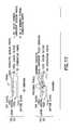
- FIG. 13shows the warning trigger for the device shown in FIG. 12 .
- FIG. 14shows the implementation of FIGS. 10 and 11 into an optical sensor based touch screen panel.
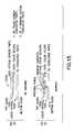
- FIG. 15shows the warning trigger for the device shown in FIG. 14 .
- FIG. 16shows the implementation of FIGS. 10 and 11 into a capacitive based touch screen panel.
- FIG. 17shows the warning trigger for the device shown in FIG. 16 .
- FIG. 18shows the implementation of FIGS. 10 and 11 into a stacked touch screen along with the corresponding warning triggers.
- FIG. 19is a logic flow diagram that illustrates a method, and the result of execution of computer program instructions, at the device in accordance with exemplary embodiments of this invention.
- the trace 900is routed around the border of the display panel 910 .
- the trace 900may be formed of indium-tin-oxide (ITO) formed on a surface of the display glass 920 , and generally around an active area 920 A of the display glass 920 .
- ITOindium-tin-oxide
- the trace 900is connected to at least two of the bumps 935 .
- this techniquewould not detect a break in the glass that occurs only in the active area 920 A of the display glass 920 . Furthermore, this technique would only provide an indication that the display glass breakage had already occurred, and not an indication that display glass breakage may be about to occur (i.e. no warning will be generated that excessive force is being applied to the display glass 920 ).
- a device 10includes a display 140 , a touch screen 150 , conductive parts (CP) 30 , and an engine (ENG) 40 , and may include microphone 100 , speaker 110 , keyboard 120 , radio 130 , vibra 160 , and camera 170 .
- the touch screen 150contains the CP 30 .
- the microphone 100converts audio from acoustic waves to electrical format.
- the speaker 110converts audio from electrical format to acoustic waves.
- the keyboard 120converts information from pressed keys to electrical format.
- the radio 130converts electrical information from/to radio waves.
- the display 140converts electrical information to readable format.
- the touch screen 150converts physical touch to an electrical format.
- the vibra 160converts electrical information to mechanical force.
- the camera 170converts images based on different levels of light of the object.
- the deviceincludes the ENG 40 and may also include software which controls these conversions as well as a user interface.
- the display 140 and the touch screen 150may further be integrated together such as a touch screen panel (TSP) 20 that forms a part of the display module 210 shown in FIG. 2 .
- TSPtouch screen panel
- the TSP 20is capable of receiving input from a user and may further be capable of displaying information received from the ENG 40 .
- the TSP 20may be coupled to a ROC 800 that has functionality as described below in regards to FIG. 11 .
- the TSP 20may also include GD 410 , SD 400 , and pixel cells with touch screen sensors (PCTSS) 1110 , also shown in FIG. 11 .
- PCTSStouch screen sensors
- the CP 30is capable of detecting a contact.
- the CP 30may be implemented between a top and a bottom glass.
- the implementation of CP 30may be further implemented as described below in regards to FIG. 10 .
- the ENG 40is capable of receiving input from the TSP 20 , microphone 100 , keyboard 120 , radio 130 , vibra 160 , and camera 170 , and is further capable of outputting to the TSP 20 .
- the exemplary embodiments of this inventionmay be implemented at least in part by computer software executable by the ENG 40 of the device 10 , or by hardware, or by a combination of software and hardware.
- the device 10may also include a base band module 200 and the display module 210 , as shown in FIG. 2 .
- the base band module 200includes the ENG 40 at least a backlight controller 220 .
- the display module 210contains the display panel 140 , a display driver 240 , the touch screen 150 , and a TSC 230 .
- the display driver 240generates VCOM, timings, etc.
- the ENG 40controls the image displayed on the display panel 140 and it can also read touch screen values via the TSC 230 .
- the display panel 140 and the touch screen panel 150may be integrated together as the TSP 20 .
- the ENG 40may also control the backlight controller 220 which sets the level of the display screen backlight.
- the display 140may be made of liquid crystal material and may be referred to as a LCD.
- FIG. 3illustrates a diagram of the display module 210 having a display panel 140 with pixel resolution of 240 ⁇ 320.
- An interface 300which includes a printed circuit, is coupled to the display driver 240 .
- the display driver 240includes a frame memory 310 , a TC 320 , an address coding block 330 , and a DAC 340 .
- FIG. 4illustrates in greater detail the display panel 140 of FIG. 3 .
- image datais inputted from the interface 300 to the frame memory 310 on the display driver 240 .
- the source of the image datamay be the ENG 40 .
- the TC 320sends timing information to the address coding block 330 where control signals are generated. Some of these control signals address the frame memory 310 .
- Image data read from the frame memory 310is a digital value or, more specifically a digital grey scale value. This digital image data is inputted into the DAC 340 where the value of the data is changed to analog image data for the column (Source: Sn, Sn+1, etc.).
- This analog image datais inputted to the display panel 140 , where a storage location for the image data is controlled by the address coding block 330 via column (source) and line (Gate: Gn, Gn+1, Gn+2, etc) control signals.
- the Line (Gate) control signalsare of a digital value (‘0’ or ‘1’) used for selecting a line of the pixels on the display panel where the analog information of the image data from column (source) is stored.
- the operation of a pixel cell, which is visible to the user, in regards to the display module of FIG. 4is also shown in FIG. 5 .
- the source driver 400outputs analog image data values on the source lines (Sn, Sn+1, Sn+2, etc.).
- the gate driver 410outputs a selection corresponding to the used gate line, and then all pixel cells of the selected gate line are updated. Only one line of pixels is updated at the same time, and the pixels are not updated on other lines. This update starts on one edge of the display panel 140 and is updated every next line. The following is an example of how two rows of pixel cells are updated.
- the analog image datais outputted on source lines (Sn, Sn+1, Sn+2, etc).
- FIG. 5shows two cases of analog image values loaded onto the gate lines. Case 1 shows two lines of pixels loaded onto gate line Gn while case 2 shows two line of pixels loaded onto gate line Gn+1.
- FIG. 6further details the display panel pixel cell control.
- the display panel 140contains a VCOM plane 610 .
- the VCOM 610 planeis a common voltage plane that is placed under the plane 620 that carries the source and gate lines.
- the voltage difference between the source and gate lines plane 620 and the VCOM 610 planemay be several volts.
- FIG. 6Bshows the VCOM voltage as a static voltage during image frame updating.
- FIG. 6Cshows the VCOM voltage changing during image frame updating.
- FIG. 7Aprovides for a separated touch screen 700 that is based on a sheet structure.
- a sheetis used as a pressure sensor and two values are measured at the end of the sheet to calculate a resistance difference.
- FIG. 7Bthen shows the touch screen panel 700 of FIG. 7A as implemented into a device.
- the touch screen panel 700is on upper glass with a connector running to a driver IC and a connector from the touch screen panel 700 .
- FIG. 7Cprovides for a display integrated touch screen 750 that is based on a matrix structure. Cross points on the display 750 are used as pressure sensors. All of the cross points are measured in order to calculate the voltage differences.
- FIG. 7Dshows the touch screen panel 750 of FIG. 7C as implemented into a device.
- the touch screen panel 750is between an upper and lower glass with only one connector running to the driver IC.
- the display integrated touch screen based on a matrix structure 750includes gate (TG) and RO lines. Every line is selected once during scanning. The selected line is readout to a ROC 800 .
- the matrix touch screen 750may operate at the same time as the display panel pixel cell control and the information is read via RO lines.
- the matrix based touch screen 750may be considered to operate in the same way as a keyboard, i.e., the user presses the touch screen and switches (SW) 810 are closed.
- display integrated touch screen panel with conductive switch matrix constructionis used to detect excessive force on the display or touch screen panel such as TSP 20 and deliver a warning to the user.
- the TSP 20may be arranged similar to the matrix touch screen 750 . Heights of the CP 30 are defined so that they can detect a pressure that may cause damage to the TSP 20 .
- CP 30are implemented between a top layer 1000 and a bottom layer 1010 . These layers may be of glass and may contain liquid crystal material 1020 and color filters 1030 . The height of the CP 30 may be different in different locations of the TSP 20 .
- the top layer 1000additionally comprises input surface 1000 A, which receives tactile input from the user. The tactile input may be from a stylus pen or the user's own finger. If the CP 30 contacts the bottom layer 1010 , the presence of the contact generates a signal. This signal allows for the ENG 40 to cause a warning message to be displayed to the user cautioning that an excessive pressing force is being applied to the top glass 1000 of the TSP 20 .
- An excessive force hereinis defined as a force that is less than the breaking threshold for the input surface 1000 A.
- the varying heights of the CP 30may be implemented as longer CPs 30 alongside the border of the TSP 20 and shorter CPs 30 in the middle of the TSP 20 . This allows for a device to take advantage of greater support around the border of the TSP 20 and where there is greater tolerance to a user's applied force.
- the touch screenis shown as a display panel with an integrated touch screen such as TSP 20 that is coupled to ROC 800 .
- TSP 20may be arranged similar to that of the matrix touch screen 750 .
- TSP 20includes GD 410 , ROC 800 , and PCTSS 1110 .
- the TSP 20receives input from the SD 400 and from the GD 410 .
- the input of SD 400is referred to as Sn and the input from the GD 410 is TGn (for a touch screen gate line) and Gn (for a display gate line).
- the PCTSS 1100includes transistors (T) 420 , touch sensors embodied as switches (SWn) 810 , capacitors (C) 430 , and liquid crystal cells (LC) 440 .
- the GD 410may include the same number of lines that are used for the display panel 140 , e.g., 320 lines (QVGA, 240 ⁇ 320).
- Transistors (T) 420 for the touch screen matrixmay be implemented in the same way as the pixel cell transistors on the TSP 20 .
- CGn lineis active when Pixel Cells 1 and 2 are updated (Gn line for selection and Sn and Sn+1 for loading) and SW 1 and SW 2 are read out (TGn line for selection and RO 1 and RO 2 lines for reading).
- FIG. 12shows the embodiment of FIG. 11 and specifically TSP 20 embodied as a display integrated touch screen panel with conductive switch matrix.
- the touch screen panel sensoris integrated onto the display panel similar to the matrix touch screen 750 and is configured to function under single touch, multi-touch, and writing conditions.
- the CP 30 of the display integrated touch screen panel with conductive matrixare implemented with varying heights. The longest CP 30 are for a touch screen function and the shortest CP 30 are for a warning function.
- SWn 810are switched and the specific SWn's that are switched depends on the force the user exerts and the location of the force on the TSP 20 .
- a warning message cautioning the user of exerting too much forcemay be displayed.
- the display of the warning messagemay be in one of the human senses e.g. mechanical, visual, or audible format.
- Mechanical formatis herein defined as format that may be of tactile feeling.
- FIG. 13shows the warning and no warning situations in regards to FIG. 12 as excessive force is applied to the TSP 20 .
- FIG. 14shows the embodiment of FIG. 11 and specifically TSP 20 embodied as an optical sensor based touch screen panel.
- the operation of FIG. 14is similar to what was described for FIG. 12 .
- sensors 1400detect light and operate in conjunction with CP 30 .
- the optical sensor parts 1400are for a touch screen function and the CP 30 are for a warning function.
- FIG. 15shows the warning and no warning situations in regards to FIG. 14 as excessive force is applied to the TSP 20 .
- FIG. 16shows the embodiment of FIG. 11 and specifically TSP 20 embodied as a capacitive based touch screen panel.
- the operation of FIG. 16is similar to what was described in FIG. 12 .
- sensors 1600detect electrical current and operate in conjunction with CP 30 .
- the capacitive sensor parts 1600are for a touch screen function and the CP 30 are for a warning function.
- FIG. 17shows the warning and no warning situations in regards to FIG. 16 as excessive force is applied to the TSP 20 .
- FIG. 18shows the embodiment of FIG. 11 , where TSP 20 includes a stacked touch screen (resistive, capacitive, etc.) 1800 .
- the stacked touch screen 1800may be on the TSP 20 when CP 30 is included only for warning purposes.
- the stacked touch screen 1800may also be under the TSP 20 e.g. in a conductive touch screen case. A warning and no warning situation are also illustrated as excessive force is applied to the TSP 20 .
- FIG. 19in accordance with an exemplary method at Block 19 A, there is a step of receiving a signal generated by a touch screen panel 20 in response to a tactile input from a user on an input surface 1000 A of the touch screen panel 20 ; and at Block 19 B in response, presenting information to a user, the information comprising a warning that the user is exerting an excessive amount of force on a surface of the touch screen panel 20 .
- the exemplary embodiments of this inventionpertain to apparatus at the touch screen panel 20 , which may be embodied as an input surface configured to generate a signal in response to tactile input from a user; and an output configured to provide an output signal when the user is exerting an excessive amount of force on the input surface.
- the various blocks shown in FIG. 19may be viewed as method steps, and/or as operations that result from operation of computer program code, and/or as a plurality of coupled logic circuit elements constructed to carry out the associated function(s).
- the various exemplary embodimentsmay be implemented in hardware or special purpose circuits, software, logic or any combination thereof.
- some aspectsmay be implemented in hardware, while other aspects may be implemented in firmware or software which may be executed by a controller, microprocessor or other computing device, although the invention is not limited thereto.
- firmware or softwarewhich may be executed by a controller, microprocessor or other computing device, although the invention is not limited thereto.
- While various aspects of the exemplary embodiments of this inventionmay be illustrated and described as block diagrams, flow charts, or using some other pictorial representation, it is well understood that these blocks, apparatus, systems, techniques or methods described herein may be implemented in, as non-limiting examples, hardware, software, firmware, special purpose circuits or logic, general purpose hardware or controller or other computing devices, or some combination thereof.
- connectionmeans any connection or coupling, either direct or indirect, between two or more elements, and may encompass the presence of one or more intermediate elements between two elements that are “connected” or “coupled” together.
- the coupling or connection between the elementscan be physical, logical, or a combination thereof.
- two elementsmay be considered to be “connected” or “coupled” together by the use of one or more wires, cables and/or printed electrical connections, as well as by the use of electromagnetic energy, such as electromagnetic energy having wavelengths in the radio frequency region, the microwave region and the optical (both visible and invisible) region, as several non-limiting and non-exhaustive examples.
Landscapes
- Engineering & Computer Science (AREA)
- General Engineering & Computer Science (AREA)
- Theoretical Computer Science (AREA)
- Human Computer Interaction (AREA)
- Physics & Mathematics (AREA)
- General Physics & Mathematics (AREA)
- User Interface Of Digital Computer (AREA)
- Position Input By Displaying (AREA)
Abstract
Description
- CP conductive parts
- DAC digital to analog converter
- GD gate driver
- LCD liquid crystal display
- LED light emitting diode
- PCTSS pixel cells with touch screen sensors
- RO readout
- ROC readout circuit
- SD source driver
- TC timing controller
- TSC touch screen controller
- TSP touch screen panel
- VCOM voltage common
Claims (30)
Priority Applications (3)
| Application Number | Priority Date | Filing Date | Title |
|---|---|---|---|
| US12/291,894US8106787B2 (en) | 2008-11-14 | 2008-11-14 | Warning system indicating excessive force on a touch screen or display |
| EP09825800AEP2353067A4 (en) | 2008-11-14 | 2009-09-21 | ALARM SYSTEM WHEN BREAKING A TOUCH SCREEN OR A DISPLAY DEVICE |
| PCT/FI2009/050752WO2010055195A1 (en) | 2008-11-14 | 2009-09-21 | Warning system for breaking touch screen or display |
Applications Claiming Priority (1)
| Application Number | Priority Date | Filing Date | Title |
|---|---|---|---|
| US12/291,894US8106787B2 (en) | 2008-11-14 | 2008-11-14 | Warning system indicating excessive force on a touch screen or display |
Publications (2)
| Publication Number | Publication Date |
|---|---|
| US20100123592A1 US20100123592A1 (en) | 2010-05-20 |
| US8106787B2true US8106787B2 (en) | 2012-01-31 |
Family
ID=42169668
Family Applications (1)
| Application Number | Title | Priority Date | Filing Date |
|---|---|---|---|
| US12/291,894Expired - Fee RelatedUS8106787B2 (en) | 2008-11-14 | 2008-11-14 | Warning system indicating excessive force on a touch screen or display |
Country Status (3)
| Country | Link |
|---|---|
| US (1) | US8106787B2 (en) |
| EP (1) | EP2353067A4 (en) |
| WO (1) | WO2010055195A1 (en) |
Cited By (50)
| Publication number | Priority date | Publication date | Assignee | Title |
|---|---|---|---|---|
| US20100309146A1 (en)* | 2009-06-05 | 2010-12-09 | Yuet-Ping Lee | Touch panel and display device |
| US20110148668A1 (en)* | 2009-12-17 | 2011-06-23 | Shenzhen Futaihong Precision Industry Co., Ltd. | System and method for protecting a resistive touch panel of a communication device |
| US20120032886A1 (en)* | 2010-02-10 | 2012-02-09 | Craig Michael Ciesla | Method for assisting user input to a device |
| US8456438B2 (en) | 2008-01-04 | 2013-06-04 | Tactus Technology, Inc. | User interface system |
| US20130154842A1 (en)* | 2010-08-19 | 2013-06-20 | Kyocera Corporation | Input apparatus |
| US8547339B2 (en) | 2008-01-04 | 2013-10-01 | Tactus Technology, Inc. | System and methods for raised touch screens |
| US8553005B2 (en) | 2008-01-04 | 2013-10-08 | Tactus Technology, Inc. | User interface system |
| US8570295B2 (en) | 2008-01-04 | 2013-10-29 | Tactus Technology, Inc. | User interface system |
| US8587548B2 (en) | 2009-07-03 | 2013-11-19 | Tactus Technology, Inc. | Method for adjusting the user interface of a device |
| US8587541B2 (en) | 2010-04-19 | 2013-11-19 | Tactus Technology, Inc. | Method for actuating a tactile interface layer |
| US20140071077A1 (en)* | 2012-09-13 | 2014-03-13 | Samsung Electronics Co. Ltd. | Method for operating electronic device based on touch pressure and the device performing the method |
| US8704790B2 (en) | 2010-10-20 | 2014-04-22 | Tactus Technology, Inc. | User interface system |
| US8922502B2 (en) | 2008-01-04 | 2014-12-30 | Tactus Technology, Inc. | User interface system |
| US8922503B2 (en) | 2008-01-04 | 2014-12-30 | Tactus Technology, Inc. | User interface system |
| US8922510B2 (en) | 2008-01-04 | 2014-12-30 | Tactus Technology, Inc. | User interface system |
| US8928621B2 (en) | 2008-01-04 | 2015-01-06 | Tactus Technology, Inc. | User interface system and method |
| US8947383B2 (en) | 2008-01-04 | 2015-02-03 | Tactus Technology, Inc. | User interface system and method |
| US9013417B2 (en) | 2008-01-04 | 2015-04-21 | Tactus Technology, Inc. | User interface system |
| US9052790B2 (en) | 2008-01-04 | 2015-06-09 | Tactus Technology, Inc. | User interface and methods |
| US9063627B2 (en) | 2008-01-04 | 2015-06-23 | Tactus Technology, Inc. | User interface and methods |
| US9075525B2 (en) | 2008-01-04 | 2015-07-07 | Tactus Technology, Inc. | User interface system |
| US9116617B2 (en) | 2009-07-03 | 2015-08-25 | Tactus Technology, Inc. | User interface enhancement system |
| US9164302B2 (en) | 2012-11-22 | 2015-10-20 | International Business Machines Corporation | Repairable touch panel |
| US9239623B2 (en) | 2010-01-05 | 2016-01-19 | Tactus Technology, Inc. | Dynamic tactile interface |
| US9274612B2 (en) | 2008-01-04 | 2016-03-01 | Tactus Technology, Inc. | User interface system |
| US9280224B2 (en) | 2012-09-24 | 2016-03-08 | Tactus Technology, Inc. | Dynamic tactile interface and methods |
| US9298261B2 (en) | 2008-01-04 | 2016-03-29 | Tactus Technology, Inc. | Method for actuating a tactile interface layer |
| US9367132B2 (en) | 2008-01-04 | 2016-06-14 | Tactus Technology, Inc. | User interface system |
| US9372565B2 (en) | 2008-01-04 | 2016-06-21 | Tactus Technology, Inc. | Dynamic tactile interface |
| US9405417B2 (en) | 2012-09-24 | 2016-08-02 | Tactus Technology, Inc. | Dynamic tactile interface and methods |
| US9423875B2 (en) | 2008-01-04 | 2016-08-23 | Tactus Technology, Inc. | Dynamic tactile interface with exhibiting optical dispersion characteristics |
| US9552065B2 (en) | 2008-01-04 | 2017-01-24 | Tactus Technology, Inc. | Dynamic tactile interface |
| US9557915B2 (en) | 2008-01-04 | 2017-01-31 | Tactus Technology, Inc. | Dynamic tactile interface |
| US9557813B2 (en) | 2013-06-28 | 2017-01-31 | Tactus Technology, Inc. | Method for reducing perceived optical distortion |
| US9588684B2 (en) | 2009-01-05 | 2017-03-07 | Tactus Technology, Inc. | Tactile interface for a computing device |
| US9588683B2 (en) | 2008-01-04 | 2017-03-07 | Tactus Technology, Inc. | Dynamic tactile interface |
| US9612659B2 (en) | 2008-01-04 | 2017-04-04 | Tactus Technology, Inc. | User interface system |
| US9720501B2 (en) | 2008-01-04 | 2017-08-01 | Tactus Technology, Inc. | Dynamic tactile interface |
| US9760172B2 (en) | 2008-01-04 | 2017-09-12 | Tactus Technology, Inc. | Dynamic tactile interface |
| US10341847B2 (en) | 2017-02-10 | 2019-07-02 | International Business Machines Corporation | Reactionary data transfer to cold storage |
| US10694010B2 (en) | 2018-07-06 | 2020-06-23 | Apple Inc. | Cover sheet and incorporated lens for a camera of an electronic device |
| US10827635B1 (en) | 2019-06-05 | 2020-11-03 | Apple Inc. | Electronic device enclosure having a textured glass component |
| US11109500B2 (en) | 2019-06-05 | 2021-08-31 | Apple Inc. | Textured glass component for an electronic device enclosure |
| US11112827B2 (en) | 2018-07-20 | 2021-09-07 | Apple Inc. | Electronic device with glass housing member |
| US11192823B2 (en) | 2019-06-05 | 2021-12-07 | Apple Inc. | Electronic devices including laser-textured glass cover members |
| US11199929B2 (en) | 2019-03-21 | 2021-12-14 | Apple Inc. | Antireflective treatment for textured enclosure components |
| US11372137B2 (en) | 2019-05-29 | 2022-06-28 | Apple Inc. | Textured cover assemblies for display applications |
| US11402669B2 (en) | 2018-04-27 | 2022-08-02 | Apple Inc. | Housing surface with tactile friction features |
| US11691912B2 (en) | 2018-12-18 | 2023-07-04 | Apple Inc. | Chemically strengthened and textured glass housing member |
| US11897809B2 (en) | 2020-09-02 | 2024-02-13 | Apple Inc. | Electronic devices with textured glass and glass ceramic components |
Families Citing this family (17)
| Publication number | Priority date | Publication date | Assignee | Title |
|---|---|---|---|---|
| FR2879803B1 (en)* | 2004-12-20 | 2007-01-19 | Dav Sa | TOUCH SURFACE ACTIVATION DEVICE, IN PARTICULAR FOR CONTROLS OF A VEHICLE |
| US20100283740A1 (en)* | 2009-05-05 | 2010-11-11 | Ching-Hung Chao | Method for Protecting Resistive Touch Panel and Computer-Readable Storage Medium and Electronic Device thereof |
| US9513737B2 (en) | 2010-09-17 | 2016-12-06 | Blackberry Limited | Touch-sensitive display with optical sensor and method |
| EP2439619B1 (en)* | 2010-09-17 | 2019-07-17 | BlackBerry Limited | Touch-sensitive display with optical sensor and method |
| US9223431B2 (en) | 2010-09-17 | 2015-12-29 | Blackberry Limited | Touch-sensitive display with depression detection and method |
| US9262002B2 (en)* | 2010-11-03 | 2016-02-16 | Qualcomm Incorporated | Force sensing touch screen |
| CN102819330B (en)* | 2011-06-07 | 2016-07-06 | 索尼爱立信移动通讯有限公司 | Electronic equipment, pressure detection method and pressure-detecting device |
| US20140152583A1 (en)* | 2012-12-03 | 2014-06-05 | International Business Machines Corporation | Optimistic placement of user interface elements on a touch screen |
| CN103309611B (en)* | 2013-05-10 | 2016-07-06 | 北京京东方光电科技有限公司 | The method of a kind of touch screen display control, Apparatus and system |
| KR101484229B1 (en)* | 2013-07-24 | 2015-01-16 | 현대자동차 주식회사 | Touch display device for vehicle and driving method thereof |
| US10282014B2 (en) | 2013-09-30 | 2019-05-07 | Apple Inc. | Operating multiple functions in a display of an electronic device |
| US9726922B1 (en) | 2013-12-20 | 2017-08-08 | Apple Inc. | Reducing display noise in an electronic device |
| US10296123B2 (en) | 2015-03-06 | 2019-05-21 | Apple Inc. | Reducing noise in a force signal in an electronic device |
| US10185397B2 (en) | 2015-03-08 | 2019-01-22 | Apple Inc. | Gap sensor for haptic feedback assembly |
| US9927905B2 (en) | 2015-08-19 | 2018-03-27 | Apple Inc. | Force touch button emulation |
| US10416811B2 (en) | 2015-09-24 | 2019-09-17 | Apple Inc. | Automatic field calibration of force input sensors |
| US10386963B2 (en) | 2017-04-06 | 2019-08-20 | International Business Machines Corporation | Detecting cracks on operatively coupled touchscreen display using pressure sense |
Citations (5)
| Publication number | Priority date | Publication date | Assignee | Title |
|---|---|---|---|---|
| EP0817110A2 (en) | 1996-06-28 | 1998-01-07 | Nokia Mobile Phones Ltd. | Terminal device with touch screen |
| JP2001054155A (en) | 1999-08-09 | 2001-02-23 | Nec Saitama Ltd | System and method for warning destruction of foldable portable telephone due to external pressure |
| WO2003042805A1 (en) | 2001-11-12 | 2003-05-22 | Myorigo Oy | Method and device for generating feedback |
| US20060103632A1 (en) | 2004-11-12 | 2006-05-18 | Eastman Kodak Company | Integral spacer dots for touch screen |
| US20060283267A1 (en) | 2005-06-20 | 2006-12-21 | Koji Tanabe | Touch panel and manufacturing method for the same |
Family Cites Families (6)
| Publication number | Priority date | Publication date | Assignee | Title |
|---|---|---|---|---|
| US6369803B2 (en)* | 1998-06-12 | 2002-04-09 | Nortel Networks Limited | Active edge user interface |
| JP2005071022A (en) | 2003-08-22 | 2005-03-17 | Canon Inc | Coordinate input device, coordinate input method |
| US20060066589A1 (en)* | 2004-09-29 | 2006-03-30 | Masanori Ozawa | Input device |
| US20070040810A1 (en)* | 2005-08-18 | 2007-02-22 | Eastman Kodak Company | Touch controlled display device |
| JP4799237B2 (en)* | 2006-03-27 | 2011-10-26 | 三洋電機株式会社 | Displacement detection sensor, displacement detection device, and terminal device |
| JP2008186279A (en)* | 2007-01-30 | 2008-08-14 | Tokai Rika Co Ltd | Remotely-operated input device |
- 2008
- 2008-11-14USUS12/291,894patent/US8106787B2/ennot_activeExpired - Fee Related
- 2009
- 2009-09-21EPEP09825800Apatent/EP2353067A4/ennot_activeWithdrawn
- 2009-09-21WOPCT/FI2009/050752patent/WO2010055195A1/enactiveApplication Filing
Patent Citations (5)
| Publication number | Priority date | Publication date | Assignee | Title |
|---|---|---|---|---|
| EP0817110A2 (en) | 1996-06-28 | 1998-01-07 | Nokia Mobile Phones Ltd. | Terminal device with touch screen |
| JP2001054155A (en) | 1999-08-09 | 2001-02-23 | Nec Saitama Ltd | System and method for warning destruction of foldable portable telephone due to external pressure |
| WO2003042805A1 (en) | 2001-11-12 | 2003-05-22 | Myorigo Oy | Method and device for generating feedback |
| US20060103632A1 (en) | 2004-11-12 | 2006-05-18 | Eastman Kodak Company | Integral spacer dots for touch screen |
| US20060283267A1 (en) | 2005-06-20 | 2006-12-21 | Koji Tanabe | Touch panel and manufacturing method for the same |
Cited By (82)
| Publication number | Priority date | Publication date | Assignee | Title |
|---|---|---|---|---|
| US9372539B2 (en) | 2008-01-04 | 2016-06-21 | Tactus Technology, Inc. | Method for actuating a tactile interface layer |
| US9372565B2 (en) | 2008-01-04 | 2016-06-21 | Tactus Technology, Inc. | Dynamic tactile interface |
| US9760172B2 (en) | 2008-01-04 | 2017-09-12 | Tactus Technology, Inc. | Dynamic tactile interface |
| US9626059B2 (en) | 2008-01-04 | 2017-04-18 | Tactus Technology, Inc. | User interface system |
| US8456438B2 (en) | 2008-01-04 | 2013-06-04 | Tactus Technology, Inc. | User interface system |
| US9619030B2 (en) | 2008-01-04 | 2017-04-11 | Tactus Technology, Inc. | User interface system and method |
| US8547339B2 (en) | 2008-01-04 | 2013-10-01 | Tactus Technology, Inc. | System and methods for raised touch screens |
| US8553005B2 (en) | 2008-01-04 | 2013-10-08 | Tactus Technology, Inc. | User interface system |
| US8570295B2 (en) | 2008-01-04 | 2013-10-29 | Tactus Technology, Inc. | User interface system |
| US9612659B2 (en) | 2008-01-04 | 2017-04-04 | Tactus Technology, Inc. | User interface system |
| US9588683B2 (en) | 2008-01-04 | 2017-03-07 | Tactus Technology, Inc. | Dynamic tactile interface |
| US9557915B2 (en) | 2008-01-04 | 2017-01-31 | Tactus Technology, Inc. | Dynamic tactile interface |
| US9552065B2 (en) | 2008-01-04 | 2017-01-24 | Tactus Technology, Inc. | Dynamic tactile interface |
| US9524025B2 (en) | 2008-01-04 | 2016-12-20 | Tactus Technology, Inc. | User interface system and method |
| US8717326B2 (en) | 2008-01-04 | 2014-05-06 | Tactus Technology, Inc. | System and methods for raised touch screens |
| US9495055B2 (en) | 2008-01-04 | 2016-11-15 | Tactus Technology, Inc. | User interface and methods |
| US8922502B2 (en) | 2008-01-04 | 2014-12-30 | Tactus Technology, Inc. | User interface system |
| US8922503B2 (en) | 2008-01-04 | 2014-12-30 | Tactus Technology, Inc. | User interface system |
| US9367132B2 (en) | 2008-01-04 | 2016-06-14 | Tactus Technology, Inc. | User interface system |
| US8928621B2 (en) | 2008-01-04 | 2015-01-06 | Tactus Technology, Inc. | User interface system and method |
| US8947383B2 (en) | 2008-01-04 | 2015-02-03 | Tactus Technology, Inc. | User interface system and method |
| US9477308B2 (en) | 2008-01-04 | 2016-10-25 | Tactus Technology, Inc. | User interface system |
| US8970403B2 (en) | 2008-01-04 | 2015-03-03 | Tactus Technology, Inc. | Method for actuating a tactile interface layer |
| US9013417B2 (en) | 2008-01-04 | 2015-04-21 | Tactus Technology, Inc. | User interface system |
| US9019228B2 (en) | 2008-01-04 | 2015-04-28 | Tactus Technology, Inc. | User interface system |
| US9035898B2 (en) | 2008-01-04 | 2015-05-19 | Tactus Technology, Inc. | System and methods for raised touch screens |
| US9052790B2 (en) | 2008-01-04 | 2015-06-09 | Tactus Technology, Inc. | User interface and methods |
| US9063627B2 (en) | 2008-01-04 | 2015-06-23 | Tactus Technology, Inc. | User interface and methods |
| US9075525B2 (en) | 2008-01-04 | 2015-07-07 | Tactus Technology, Inc. | User interface system |
| US9098141B2 (en) | 2008-01-04 | 2015-08-04 | Tactus Technology, Inc. | User interface system |
| US9448630B2 (en) | 2008-01-04 | 2016-09-20 | Tactus Technology, Inc. | Method for actuating a tactile interface layer |
| US9430074B2 (en) | 2008-01-04 | 2016-08-30 | Tactus Technology, Inc. | Dynamic tactile interface |
| US9207795B2 (en) | 2008-01-04 | 2015-12-08 | Tactus Technology, Inc. | User interface system |
| US9229571B2 (en) | 2008-01-04 | 2016-01-05 | Tactus Technology, Inc. | Method for adjusting the user interface of a device |
| US9423875B2 (en) | 2008-01-04 | 2016-08-23 | Tactus Technology, Inc. | Dynamic tactile interface with exhibiting optical dispersion characteristics |
| US9274612B2 (en) | 2008-01-04 | 2016-03-01 | Tactus Technology, Inc. | User interface system |
| US9720501B2 (en) | 2008-01-04 | 2017-08-01 | Tactus Technology, Inc. | Dynamic tactile interface |
| US9298261B2 (en) | 2008-01-04 | 2016-03-29 | Tactus Technology, Inc. | Method for actuating a tactile interface layer |
| US8922510B2 (en) | 2008-01-04 | 2014-12-30 | Tactus Technology, Inc. | User interface system |
| US9588684B2 (en) | 2009-01-05 | 2017-03-07 | Tactus Technology, Inc. | Tactile interface for a computing device |
| US20100309146A1 (en)* | 2009-06-05 | 2010-12-09 | Yuet-Ping Lee | Touch panel and display device |
| US8587548B2 (en) | 2009-07-03 | 2013-11-19 | Tactus Technology, Inc. | Method for adjusting the user interface of a device |
| US9116617B2 (en) | 2009-07-03 | 2015-08-25 | Tactus Technology, Inc. | User interface enhancement system |
| US20110148668A1 (en)* | 2009-12-17 | 2011-06-23 | Shenzhen Futaihong Precision Industry Co., Ltd. | System and method for protecting a resistive touch panel of a communication device |
| US8253710B2 (en)* | 2009-12-17 | 2012-08-28 | Shenzhen Futaihong Precision Industry Co., Ltd. | System and method for protecting a resistive touch panel of a communication device |
| US9298262B2 (en) | 2010-01-05 | 2016-03-29 | Tactus Technology, Inc. | Dynamic tactile interface |
| US9239623B2 (en) | 2010-01-05 | 2016-01-19 | Tactus Technology, Inc. | Dynamic tactile interface |
| US20120032886A1 (en)* | 2010-02-10 | 2012-02-09 | Craig Michael Ciesla | Method for assisting user input to a device |
| US8619035B2 (en)* | 2010-02-10 | 2013-12-31 | Tactus Technology, Inc. | Method for assisting user input to a device |
| US8723832B2 (en) | 2010-04-19 | 2014-05-13 | Tactus Technology, Inc. | Method for actuating a tactile interface layer |
| US8587541B2 (en) | 2010-04-19 | 2013-11-19 | Tactus Technology, Inc. | Method for actuating a tactile interface layer |
| US20130154842A1 (en)* | 2010-08-19 | 2013-06-20 | Kyocera Corporation | Input apparatus |
| US8947248B2 (en)* | 2010-08-19 | 2015-02-03 | Kyocera Corporation | Input apparatus |
| US8704790B2 (en) | 2010-10-20 | 2014-04-22 | Tactus Technology, Inc. | User interface system |
| US9342198B2 (en)* | 2012-09-13 | 2016-05-17 | Samsung Electronics Co., Ltd. | Method for operating electronic device based on touch pressure and the device performing the method |
| US20140071077A1 (en)* | 2012-09-13 | 2014-03-13 | Samsung Electronics Co. Ltd. | Method for operating electronic device based on touch pressure and the device performing the method |
| US9405417B2 (en) | 2012-09-24 | 2016-08-02 | Tactus Technology, Inc. | Dynamic tactile interface and methods |
| US9280224B2 (en) | 2012-09-24 | 2016-03-08 | Tactus Technology, Inc. | Dynamic tactile interface and methods |
| US9164302B2 (en) | 2012-11-22 | 2015-10-20 | International Business Machines Corporation | Repairable touch panel |
| US9557813B2 (en) | 2013-06-28 | 2017-01-31 | Tactus Technology, Inc. | Method for reducing perceived optical distortion |
| US10341847B2 (en) | 2017-02-10 | 2019-07-02 | International Business Machines Corporation | Reactionary data transfer to cold storage |
| US11402669B2 (en) | 2018-04-27 | 2022-08-02 | Apple Inc. | Housing surface with tactile friction features |
| US10694010B2 (en) | 2018-07-06 | 2020-06-23 | Apple Inc. | Cover sheet and incorporated lens for a camera of an electronic device |
| US10917505B2 (en) | 2018-07-06 | 2021-02-09 | Apple Inc. | Cover sheet and incorporated lens for a camera of an electronic device |
| US11822385B2 (en) | 2018-07-20 | 2023-11-21 | Apple Inc. | Electronic device with glass housing member |
| US11112827B2 (en) | 2018-07-20 | 2021-09-07 | Apple Inc. | Electronic device with glass housing member |
| US12197246B2 (en) | 2018-07-20 | 2025-01-14 | Apple Inc. | Electronic device with glass housing member |
| US11397449B2 (en) | 2018-07-20 | 2022-07-26 | Apple Inc. | Electronic device with glass housing member |
| US11691912B2 (en) | 2018-12-18 | 2023-07-04 | Apple Inc. | Chemically strengthened and textured glass housing member |
| US11199929B2 (en) | 2019-03-21 | 2021-12-14 | Apple Inc. | Antireflective treatment for textured enclosure components |
| US11372137B2 (en) | 2019-05-29 | 2022-06-28 | Apple Inc. | Textured cover assemblies for display applications |
| US11940594B2 (en) | 2019-05-29 | 2024-03-26 | Apple Inc. | Textured cover assemblies for display applications |
| US11533817B2 (en) | 2019-06-05 | 2022-12-20 | Apple Inc. | Textured glass component for an electronic device enclosure |
| US11192823B2 (en) | 2019-06-05 | 2021-12-07 | Apple Inc. | Electronic devices including laser-textured glass cover members |
| US11109500B2 (en) | 2019-06-05 | 2021-08-31 | Apple Inc. | Textured glass component for an electronic device enclosure |
| US11849554B2 (en) | 2019-06-05 | 2023-12-19 | Apple Inc. | Electronic device enclosure having a textured glass component |
| US11910551B2 (en) | 2019-06-05 | 2024-02-20 | Apple Inc. | Textured glass component for an electronic device enclosure |
| US11369028B2 (en) | 2019-06-05 | 2022-06-21 | Apple Inc. | Electronic device enclosure having a textured glass component |
| US12177999B2 (en) | 2019-06-05 | 2024-12-24 | Apple Inc. | Textured glass component for an electronic device enclosure |
| US10827635B1 (en) | 2019-06-05 | 2020-11-03 | Apple Inc. | Electronic device enclosure having a textured glass component |
| US11897809B2 (en) | 2020-09-02 | 2024-02-13 | Apple Inc. | Electronic devices with textured glass and glass ceramic components |
| US12215053B2 (en) | 2020-09-02 | 2025-02-04 | Apple Inc. | Electronic devices with textured glass and glass ceramic components |
Also Published As
| Publication number | Publication date |
|---|---|
| EP2353067A4 (en) | 2013-03-20 |
| EP2353067A1 (en) | 2011-08-10 |
| US20100123592A1 (en) | 2010-05-20 |
| WO2010055195A1 (en) | 2010-05-20 |
Similar Documents
| Publication | Publication Date | Title |
|---|---|---|
| US8106787B2 (en) | Warning system indicating excessive force on a touch screen or display | |
| KR101641690B1 (en) | Display device with integrated touch screen | |
| US9372536B2 (en) | Touch screen with tactile feedback | |
| US10318054B2 (en) | Display device and display method | |
| JP5485512B2 (en) | Display device and driving method thereof | |
| EP2771772B1 (en) | Touchscreen with haptic feedback | |
| US8174505B2 (en) | Touch screen display device and driving method of the same | |
| EP2887186B1 (en) | Display device with integrated touch screen | |
| US9158377B2 (en) | Electronic device to maintain contact position during haptic feedback | |
| CN107728831B (en) | Pressure touch method of touch input device | |
| US10234977B2 (en) | Pressure sensing touch device | |
| CN104636012A (en) | Display device with integrated touch screen | |
| CN101271211A (en) | Liquid crystal device, electronic device, and position detection method | |
| KR20160039765A (en) | Display device indlucing touch sensor | |
| KR20160087467A (en) | Method for driving touch screen panel | |
| CN112470108B (en) | Mechanical keyboard overlay for touch screen | |
| KR101816549B1 (en) | Touch display apparatus | |
| KR101733728B1 (en) | Display device with integrated touch screen | |
| KR20100042761A (en) | Method of correcting position of touched point on touch-screen | |
| US9916026B2 (en) | Electronic device and control method for electronic device | |
| KR20160089942A (en) | Touch recognition mehtod for display device and display device using the same | |
| KR101194662B1 (en) | Method and device for detecting touch input | |
| US8525807B2 (en) | Flat display, touch device and touch detecting method | |
| KR20160103245A (en) | Touch sensing apparatus and method for driving the same | |
| US20130307807A1 (en) | Electronic device |
Legal Events
| Date | Code | Title | Description |
|---|---|---|---|
| AS | Assignment | Owner name:NOKIA CORPORATION,FINLAND Free format text:ASSIGNMENT OF ASSIGNORS INTEREST;ASSIGNOR:NURMI, JUHA HARRI-PEKKA;REEL/FRAME:022181/0674 Effective date:20090116 Owner name:NOKIA CORPORATION, FINLAND Free format text:ASSIGNMENT OF ASSIGNORS INTEREST;ASSIGNOR:NURMI, JUHA HARRI-PEKKA;REEL/FRAME:022181/0674 Effective date:20090116 | |
| ZAAA | Notice of allowance and fees due | Free format text:ORIGINAL CODE: NOA | |
| ZAAB | Notice of allowance mailed | Free format text:ORIGINAL CODE: MN/=. | |
| FEPP | Fee payment procedure | Free format text:PAYOR NUMBER ASSIGNED (ORIGINAL EVENT CODE: ASPN); ENTITY STATUS OF PATENT OWNER: LARGE ENTITY | |
| STCF | Information on status: patent grant | Free format text:PATENTED CASE | |
| AS | Assignment | Owner name:NOKIA TECHNOLOGIES OY, FINLAND Free format text:ASSIGNMENT OF ASSIGNORS INTEREST;ASSIGNOR:NOKIA CORPORATION;REEL/FRAME:035496/0653 Effective date:20150116 | |
| FPAY | Fee payment | Year of fee payment:4 | |
| MAFP | Maintenance fee payment | Free format text:PAYMENT OF MAINTENANCE FEE, 8TH YEAR, LARGE ENTITY (ORIGINAL EVENT CODE: M1552); ENTITY STATUS OF PATENT OWNER: LARGE ENTITY Year of fee payment:8 | |
| FEPP | Fee payment procedure | Free format text:MAINTENANCE FEE REMINDER MAILED (ORIGINAL EVENT CODE: REM.); ENTITY STATUS OF PATENT OWNER: LARGE ENTITY | |
| LAPS | Lapse for failure to pay maintenance fees | Free format text:PATENT EXPIRED FOR FAILURE TO PAY MAINTENANCE FEES (ORIGINAL EVENT CODE: EXP.); ENTITY STATUS OF PATENT OWNER: LARGE ENTITY | |
| STCH | Information on status: patent discontinuation | Free format text:PATENT EXPIRED DUE TO NONPAYMENT OF MAINTENANCE FEES UNDER 37 CFR 1.362 | |
| FP | Lapsed due to failure to pay maintenance fee | Effective date:20240131 |