US8105383B2 - Manufactured bone composite implant shaped to conform to a prepared implantation space - Google Patents
Manufactured bone composite implant shaped to conform to a prepared implantation spaceDownload PDFInfo
- Publication number
- US8105383B2 US8105383B2US11/089,087US8908705AUS8105383B2US 8105383 B2US8105383 B2US 8105383B2US 8908705 AUS8908705 AUS 8908705AUS 8105383 B2US8105383 B2US 8105383B2
- Authority
- US
- United States
- Prior art keywords
- implant
- bone
- adjacent vertebral
- vertebral bodies
- leading end
- Prior art date
- Legal status (The legal status is an assumption and is not a legal conclusion. Google has not performed a legal analysis and makes no representation as to the accuracy of the status listed.)
- Expired - Fee Related, expires
Links
Images


Classifications
- A—HUMAN NECESSITIES
- A61—MEDICAL OR VETERINARY SCIENCE; HYGIENE
- A61F—FILTERS IMPLANTABLE INTO BLOOD VESSELS; PROSTHESES; DEVICES PROVIDING PATENCY TO, OR PREVENTING COLLAPSING OF, TUBULAR STRUCTURES OF THE BODY, e.g. STENTS; ORTHOPAEDIC, NURSING OR CONTRACEPTIVE DEVICES; FOMENTATION; TREATMENT OR PROTECTION OF EYES OR EARS; BANDAGES, DRESSINGS OR ABSORBENT PADS; FIRST-AID KITS
- A61F2/00—Filters implantable into blood vessels; Prostheses, i.e. artificial substitutes or replacements for parts of the body; Appliances for connecting them with the body; Devices providing patency to, or preventing collapsing of, tubular structures of the body, e.g. stents
- A61F2/02—Prostheses implantable into the body
- A61F2/30—Joints
- A61F2/44—Joints for the spine, e.g. vertebrae, spinal discs
- A61F2/4455—Joints for the spine, e.g. vertebrae, spinal discs for the fusion of spinal bodies, e.g. intervertebral fusion of adjacent spinal bodies, e.g. fusion cages
- A61F2/4465—Joints for the spine, e.g. vertebrae, spinal discs for the fusion of spinal bodies, e.g. intervertebral fusion of adjacent spinal bodies, e.g. fusion cages having a circular or kidney shaped cross-section substantially perpendicular to the axis of the spine
- A—HUMAN NECESSITIES
- A61—MEDICAL OR VETERINARY SCIENCE; HYGIENE
- A61F—FILTERS IMPLANTABLE INTO BLOOD VESSELS; PROSTHESES; DEVICES PROVIDING PATENCY TO, OR PREVENTING COLLAPSING OF, TUBULAR STRUCTURES OF THE BODY, e.g. STENTS; ORTHOPAEDIC, NURSING OR CONTRACEPTIVE DEVICES; FOMENTATION; TREATMENT OR PROTECTION OF EYES OR EARS; BANDAGES, DRESSINGS OR ABSORBENT PADS; FIRST-AID KITS
- A61F2/00—Filters implantable into blood vessels; Prostheses, i.e. artificial substitutes or replacements for parts of the body; Appliances for connecting them with the body; Devices providing patency to, or preventing collapsing of, tubular structures of the body, e.g. stents
- A61F2/02—Prostheses implantable into the body
- A61F2/28—Bones
- A—HUMAN NECESSITIES
- A61—MEDICAL OR VETERINARY SCIENCE; HYGIENE
- A61B—DIAGNOSIS; SURGERY; IDENTIFICATION
- A61B17/00—Surgical instruments, devices or methods
- A61B17/56—Surgical instruments or methods for treatment of bones or joints; Devices specially adapted therefor
- A61B17/58—Surgical instruments or methods for treatment of bones or joints; Devices specially adapted therefor for osteosynthesis, e.g. bone plates, screws or setting implements
- A61B17/68—Internal fixation devices, including fasteners and spinal fixators, even if a part thereof projects from the skin
- A61B17/84—Fasteners therefor or fasteners being internal fixation devices
- A61B17/86—Pins or screws or threaded wires; nuts therefor
- A—HUMAN NECESSITIES
- A61—MEDICAL OR VETERINARY SCIENCE; HYGIENE
- A61F—FILTERS IMPLANTABLE INTO BLOOD VESSELS; PROSTHESES; DEVICES PROVIDING PATENCY TO, OR PREVENTING COLLAPSING OF, TUBULAR STRUCTURES OF THE BODY, e.g. STENTS; ORTHOPAEDIC, NURSING OR CONTRACEPTIVE DEVICES; FOMENTATION; TREATMENT OR PROTECTION OF EYES OR EARS; BANDAGES, DRESSINGS OR ABSORBENT PADS; FIRST-AID KITS
- A61F2/00—Filters implantable into blood vessels; Prostheses, i.e. artificial substitutes or replacements for parts of the body; Appliances for connecting them with the body; Devices providing patency to, or preventing collapsing of, tubular structures of the body, e.g. stents
- A61F2/02—Prostheses implantable into the body
- A61F2/30—Joints
- A61F2/3094—Designing or manufacturing processes
- A61F2/30965—Reinforcing the prosthesis by embedding particles or fibres during moulding or dipping
- A—HUMAN NECESSITIES
- A61—MEDICAL OR VETERINARY SCIENCE; HYGIENE
- A61F—FILTERS IMPLANTABLE INTO BLOOD VESSELS; PROSTHESES; DEVICES PROVIDING PATENCY TO, OR PREVENTING COLLAPSING OF, TUBULAR STRUCTURES OF THE BODY, e.g. STENTS; ORTHOPAEDIC, NURSING OR CONTRACEPTIVE DEVICES; FOMENTATION; TREATMENT OR PROTECTION OF EYES OR EARS; BANDAGES, DRESSINGS OR ABSORBENT PADS; FIRST-AID KITS
- A61F2/00—Filters implantable into blood vessels; Prostheses, i.e. artificial substitutes or replacements for parts of the body; Appliances for connecting them with the body; Devices providing patency to, or preventing collapsing of, tubular structures of the body, e.g. stents
- A61F2/02—Prostheses implantable into the body
- A61F2/30—Joints
- A61F2/44—Joints for the spine, e.g. vertebrae, spinal discs
- A61F2/442—Intervertebral or spinal discs, e.g. resilient
- A—HUMAN NECESSITIES
- A61—MEDICAL OR VETERINARY SCIENCE; HYGIENE
- A61F—FILTERS IMPLANTABLE INTO BLOOD VESSELS; PROSTHESES; DEVICES PROVIDING PATENCY TO, OR PREVENTING COLLAPSING OF, TUBULAR STRUCTURES OF THE BODY, e.g. STENTS; ORTHOPAEDIC, NURSING OR CONTRACEPTIVE DEVICES; FOMENTATION; TREATMENT OR PROTECTION OF EYES OR EARS; BANDAGES, DRESSINGS OR ABSORBENT PADS; FIRST-AID KITS
- A61F2/00—Filters implantable into blood vessels; Prostheses, i.e. artificial substitutes or replacements for parts of the body; Appliances for connecting them with the body; Devices providing patency to, or preventing collapsing of, tubular structures of the body, e.g. stents
- A61F2/02—Prostheses implantable into the body
- A61F2/28—Bones
- A61F2002/2817—Bone stimulation by chemical reactions or by osteogenic or biological products for enhancing ossification, e.g. by bone morphogenetic or morphogenic proteins [BMP] or by transforming growth factors [TGF]
- A—HUMAN NECESSITIES
- A61—MEDICAL OR VETERINARY SCIENCE; HYGIENE
- A61F—FILTERS IMPLANTABLE INTO BLOOD VESSELS; PROSTHESES; DEVICES PROVIDING PATENCY TO, OR PREVENTING COLLAPSING OF, TUBULAR STRUCTURES OF THE BODY, e.g. STENTS; ORTHOPAEDIC, NURSING OR CONTRACEPTIVE DEVICES; FOMENTATION; TREATMENT OR PROTECTION OF EYES OR EARS; BANDAGES, DRESSINGS OR ABSORBENT PADS; FIRST-AID KITS
- A61F2/00—Filters implantable into blood vessels; Prostheses, i.e. artificial substitutes or replacements for parts of the body; Appliances for connecting them with the body; Devices providing patency to, or preventing collapsing of, tubular structures of the body, e.g. stents
- A61F2/02—Prostheses implantable into the body
- A61F2/30—Joints
- A61F2002/30001—Additional features of subject-matter classified in A61F2/28, A61F2/30 and subgroups thereof
- A61F2002/30003—Material related properties of the prosthesis or of a coating on the prosthesis
- A61F2002/3006—Properties of materials and coating materials
- A61F2002/30062—(bio)absorbable, biodegradable, bioerodable, (bio)resorbable, resorptive
- A—HUMAN NECESSITIES
- A61—MEDICAL OR VETERINARY SCIENCE; HYGIENE
- A61F—FILTERS IMPLANTABLE INTO BLOOD VESSELS; PROSTHESES; DEVICES PROVIDING PATENCY TO, OR PREVENTING COLLAPSING OF, TUBULAR STRUCTURES OF THE BODY, e.g. STENTS; ORTHOPAEDIC, NURSING OR CONTRACEPTIVE DEVICES; FOMENTATION; TREATMENT OR PROTECTION OF EYES OR EARS; BANDAGES, DRESSINGS OR ABSORBENT PADS; FIRST-AID KITS
- A61F2/00—Filters implantable into blood vessels; Prostheses, i.e. artificial substitutes or replacements for parts of the body; Appliances for connecting them with the body; Devices providing patency to, or preventing collapsing of, tubular structures of the body, e.g. stents
- A61F2/02—Prostheses implantable into the body
- A61F2/30—Joints
- A61F2002/30001—Additional features of subject-matter classified in A61F2/28, A61F2/30 and subgroups thereof
- A61F2002/30316—The prosthesis having different structural features at different locations within the same prosthesis; Connections between prosthetic parts; Special structural features of bone or joint prostheses not otherwise provided for
- A61F2002/30535—Special structural features of bone or joint prostheses not otherwise provided for
- A61F2002/30593—Special structural features of bone or joint prostheses not otherwise provided for hollow
- A—HUMAN NECESSITIES
- A61—MEDICAL OR VETERINARY SCIENCE; HYGIENE
- A61F—FILTERS IMPLANTABLE INTO BLOOD VESSELS; PROSTHESES; DEVICES PROVIDING PATENCY TO, OR PREVENTING COLLAPSING OF, TUBULAR STRUCTURES OF THE BODY, e.g. STENTS; ORTHOPAEDIC, NURSING OR CONTRACEPTIVE DEVICES; FOMENTATION; TREATMENT OR PROTECTION OF EYES OR EARS; BANDAGES, DRESSINGS OR ABSORBENT PADS; FIRST-AID KITS
- A61F2/00—Filters implantable into blood vessels; Prostheses, i.e. artificial substitutes or replacements for parts of the body; Appliances for connecting them with the body; Devices providing patency to, or preventing collapsing of, tubular structures of the body, e.g. stents
- A61F2/02—Prostheses implantable into the body
- A61F2/30—Joints
- A61F2/30767—Special external or bone-contacting surface, e.g. coating for improving bone ingrowth
- A61F2/30771—Special external or bone-contacting surface, e.g. coating for improving bone ingrowth applied in original prostheses, e.g. holes or grooves
- A61F2002/30772—Apertures or holes, e.g. of circular cross section
- A61F2002/30784—Plurality of holes
- A61F2002/30787—Plurality of holes inclined obliquely with respect to each other
- A—HUMAN NECESSITIES
- A61—MEDICAL OR VETERINARY SCIENCE; HYGIENE
- A61F—FILTERS IMPLANTABLE INTO BLOOD VESSELS; PROSTHESES; DEVICES PROVIDING PATENCY TO, OR PREVENTING COLLAPSING OF, TUBULAR STRUCTURES OF THE BODY, e.g. STENTS; ORTHOPAEDIC, NURSING OR CONTRACEPTIVE DEVICES; FOMENTATION; TREATMENT OR PROTECTION OF EYES OR EARS; BANDAGES, DRESSINGS OR ABSORBENT PADS; FIRST-AID KITS
- A61F2/00—Filters implantable into blood vessels; Prostheses, i.e. artificial substitutes or replacements for parts of the body; Appliances for connecting them with the body; Devices providing patency to, or preventing collapsing of, tubular structures of the body, e.g. stents
- A61F2/02—Prostheses implantable into the body
- A61F2/30—Joints
- A61F2/30767—Special external or bone-contacting surface, e.g. coating for improving bone ingrowth
- A61F2/30771—Special external or bone-contacting surface, e.g. coating for improving bone ingrowth applied in original prostheses, e.g. holes or grooves
- A61F2002/30841—Sharp anchoring protrusions for impaction into the bone, e.g. sharp pins, spikes
- A—HUMAN NECESSITIES
- A61—MEDICAL OR VETERINARY SCIENCE; HYGIENE
- A61F—FILTERS IMPLANTABLE INTO BLOOD VESSELS; PROSTHESES; DEVICES PROVIDING PATENCY TO, OR PREVENTING COLLAPSING OF, TUBULAR STRUCTURES OF THE BODY, e.g. STENTS; ORTHOPAEDIC, NURSING OR CONTRACEPTIVE DEVICES; FOMENTATION; TREATMENT OR PROTECTION OF EYES OR EARS; BANDAGES, DRESSINGS OR ABSORBENT PADS; FIRST-AID KITS
- A61F2/00—Filters implantable into blood vessels; Prostheses, i.e. artificial substitutes or replacements for parts of the body; Appliances for connecting them with the body; Devices providing patency to, or preventing collapsing of, tubular structures of the body, e.g. stents
- A61F2/02—Prostheses implantable into the body
- A61F2/30—Joints
- A61F2/30767—Special external or bone-contacting surface, e.g. coating for improving bone ingrowth
- A61F2/30771—Special external or bone-contacting surface, e.g. coating for improving bone ingrowth applied in original prostheses, e.g. holes or grooves
- A61F2002/30878—Special external or bone-contacting surface, e.g. coating for improving bone ingrowth applied in original prostheses, e.g. holes or grooves with non-sharp protrusions, for instance contacting the bone for anchoring, e.g. keels, pegs, pins, posts, shanks, stems, struts
- A61F2002/30891—Plurality of protrusions
- A61F2002/30892—Plurality of protrusions parallel
- A—HUMAN NECESSITIES
- A61—MEDICAL OR VETERINARY SCIENCE; HYGIENE
- A61F—FILTERS IMPLANTABLE INTO BLOOD VESSELS; PROSTHESES; DEVICES PROVIDING PATENCY TO, OR PREVENTING COLLAPSING OF, TUBULAR STRUCTURES OF THE BODY, e.g. STENTS; ORTHOPAEDIC, NURSING OR CONTRACEPTIVE DEVICES; FOMENTATION; TREATMENT OR PROTECTION OF EYES OR EARS; BANDAGES, DRESSINGS OR ABSORBENT PADS; FIRST-AID KITS
- A61F2/00—Filters implantable into blood vessels; Prostheses, i.e. artificial substitutes or replacements for parts of the body; Appliances for connecting them with the body; Devices providing patency to, or preventing collapsing of, tubular structures of the body, e.g. stents
- A61F2/02—Prostheses implantable into the body
- A61F2/30—Joints
- A61F2/30767—Special external or bone-contacting surface, e.g. coating for improving bone ingrowth
- A61F2/30771—Special external or bone-contacting surface, e.g. coating for improving bone ingrowth applied in original prostheses, e.g. holes or grooves
- A61F2002/30904—Special external or bone-contacting surface, e.g. coating for improving bone ingrowth applied in original prostheses, e.g. holes or grooves serrated profile, i.e. saw-toothed
- A—HUMAN NECESSITIES
- A61—MEDICAL OR VETERINARY SCIENCE; HYGIENE
- A61F—FILTERS IMPLANTABLE INTO BLOOD VESSELS; PROSTHESES; DEVICES PROVIDING PATENCY TO, OR PREVENTING COLLAPSING OF, TUBULAR STRUCTURES OF THE BODY, e.g. STENTS; ORTHOPAEDIC, NURSING OR CONTRACEPTIVE DEVICES; FOMENTATION; TREATMENT OR PROTECTION OF EYES OR EARS; BANDAGES, DRESSINGS OR ABSORBENT PADS; FIRST-AID KITS
- A61F2210/00—Particular material properties of prostheses classified in groups A61F2/00 - A61F2/26 or A61F2/82 or A61F9/00 or A61F11/00 or subgroups thereof
- A61F2210/0004—Particular material properties of prostheses classified in groups A61F2/00 - A61F2/26 or A61F2/82 or A61F9/00 or A61F11/00 or subgroups thereof bioabsorbable
- A—HUMAN NECESSITIES
- A61—MEDICAL OR VETERINARY SCIENCE; HYGIENE
- A61F—FILTERS IMPLANTABLE INTO BLOOD VESSELS; PROSTHESES; DEVICES PROVIDING PATENCY TO, OR PREVENTING COLLAPSING OF, TUBULAR STRUCTURES OF THE BODY, e.g. STENTS; ORTHOPAEDIC, NURSING OR CONTRACEPTIVE DEVICES; FOMENTATION; TREATMENT OR PROTECTION OF EYES OR EARS; BANDAGES, DRESSINGS OR ABSORBENT PADS; FIRST-AID KITS
- A61F2310/00—Prostheses classified in A61F2/28 or A61F2/30 - A61F2/44 being constructed from or coated with a particular material
- A61F2310/00005—The prosthesis being constructed from a particular material
- A61F2310/00179—Ceramics or ceramic-like structures
Definitions
- the diaphysisis the shaft of a long bone, as distinguished from the epiphysis, the end of the bone forming the joints.
- a complete bone ringis formed with the medulary canal forming an opening through the ring.
- Such ringsare generally harvested from femurs for use in the lumbar spine.
- Other bones from the arm or leg or other part of the skeletonmay be useful in various regions of the spine.
- diaphyseal bone ringssuch as those harvested from human femurs
- femoral ringsare formed by making two spaced apart cuts approximately perpendicular to the long axis of the diaphyseal portion of a human cadaveric femur. The cuts are generally spaced apart so as to form a ring having a height corresponding to the restored disc space or slightly greater.
- Femoral ring bone graftsare placed into the spine within and across the height of the space previously occupied by a spinal disc between adjacent vertebral bodies to achieve interbody fusion of those vertebral bodies through the disc space. The femoral ring bone graft is incorporated into the bony fusion over time.
- Bone rings that are entirely or almost entirely made of cortical boneoffer the advantages of that material including an appropriate modulus of elasticity and strength for the prescribed use, the capacity to be bioactive, including being osteoconductive, osteoinductive, osteogenic, and to more generally provide a good substrate for the formation of new bone as fusion occurs. Further, by being bioabsorable the bone material is replaced by the patient's own bone over time, thereby preventing stress shielding and leading to the eventual elimination of any foreign body from the implantation site.
- the present inventionis directed to a major long bone ring implant preferably, but not necessarily, an implant formed from a diaphyseal ring for insertion into an implantation space formed across a spinal disc between two adjacent vertebral bodies of the spine.
- the bone ring implantis preferably used in an implantation space having a wall portion, lip, or ridge with a flat portion for abutting the leading end of the bone ring implant.
- Such an implantation spacecan be formed with the instrumentation and method set forth in applicant's U.S. application Ser. No. 08/688,758. titled “Milling Instrumentation and Method for Preparing a Space Between Adjacent Vertebral Bodies”, incorporated by reference herein.
- the bone ring implant of the present inventioncan be useful in implantation spaces formed by other techniques, such as for example, applicant's U.S. application Ser. No. 09/490,901, titled “Instrument And Method For Creating An Intervertebral Space For Receiving An Implant”, incorporated by reference herein.
- the bone ring implantis manufactured and machined to have a leading end and a trailing end opposite the leading end connected by opposed sides or walls.
- the leading end, trailing end, and the opposed sides or wallspreferably form one continuous perimeter having opposed upper and lower vertebral body engaging surfaces.
- the bone ring implants of the present inventionhave a substantial flat portion at the leading end formed by cutting or machining the perimeter of the bone to create a straight cut portion at the leading end.
- the straight cut portionis generally oriented at 90° to the mid-longitudinal axis of the bone ring implant as defined by a line passing through the center of the bone ring implant from its leading end to its trailing end.
- the bone ring implantis further machined so that one and preferably both of the opposed sides have portions that are straight and at a 90° angle to the straight cut portion of the leading end to produce straight portions that are outwardly facing. These straight portions are generally oriented parallel to the implant's longitudinal axis.
- the opposed sidesmay be machined to be generally parallel to each other over at least a portion of the sides and may be aligned or offset from each other along the implant sides.
- the present inventionconsists of the unique machined structures of the bone ring implant, as well as may be used in combination with lockable screws, and preferably screw locks each preferably made of cortical bone or of a bioresorbable material.
- the bone ring implant of the present inventionmay be machined so as to be adapted to receive through its trailing end at least a pair of opposed appropriately sized bone screws preferably, but not necessarily, made of cortical bone.
- the bone engaging screwsmay be aligned or offset from each other. At least one screw engages each of the vertebral bodies adjacent a disc space to be fused and into which the bone ring implant is implanted.
- the bone ring implant of the present inventionis preferably further machined and adapted to receive locks, preferably made of cortical bone, at the trailing end for securing the bone engaging screws therein and preventing the screws from backing out.
- the bone ring implant, bone screws, and/or lockscan be made of a bioresorbable material, including but not limited to cortical bone, plastics and composite plastics. Suitable plastics may include those comprising lactides, galactides, glycolide, capronlactone, trimethylene carbonate, or dioxanone in various polymers, and/or combinations thereof.
- the bone ring implant of the present inventioncan be further machined to have a specialized bone engaging surface configuration designed to enhance stability and resist motion imparted to each of the opposed upper and lower vertebrae engaging surfaces of the bone ring implant, such as for example the surface described in applicant's U.S. application Ser. No. 09/457,228 titled “Spinal Implant Surface Configuration” incorporated by reference herein.
- the bone ring implant of the present inventionis preferably for anterior implantation into the disc space and is preferably taller at the trailing end than at the leading end (the leading end being adapted to introduce the implant into the spine) so as to provide for a desired amount of lordosis.
- the bone ring implanthas been described as diaphyseal rings by way of example of one embodiment of the present invention. It should be clearly understood that such rings may be formed of bone that may be at least in part metaphyseal if sufficiently strong for the intended purpose.
- the bone ring implantsmay be made of a manufactured bone composite comprising of particles or filaments of bone and a bioresorbable plastic or ceramic or other suitable material without departing from the inventive concepts of the present invention, prime of which is a manufactured implant comprising cortical bone with a flat leading portion and preferably at least partial side portions that are flat and preferably 90° to the front of the implant.
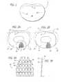
- FIG. 1is a top plan view of a vertebral body with preferably a machined implantation socket created therein for receiving a bone ring implant in accordance with the present invention.
- FIG. 2Ais a top plan view of a vertebral body showing the desired implantation socket with a first bone ring implant with a bone-engaging surface formed thereon and showing the machining of the bone ring required to obtain that ring's best fit to the recipient site (socket) within that vertebral body.
- FIG. 2Bis a top plan view of a vertebral body showing the desired implantation socket with a second bone ring implant with the bone-engaging surface formed thereon and showing the machining of the bone ring required to obtain that ring's best fit to the recipient site (socket) within that vertebral body.
- FIG. 3Ais an enlarged fragmentary view along line 3 - 3 of FIG. 2A of the bone-engaging surface.
- FIG. 3Bis a side view of FIG. 3A illustrating the configuration of the bone-engaging surface.
- FIG. 4is a trailing end view of a bone ring implant in accordance with an embodiment of the present invention having openings oriented toward the adjacent vertebral bodies for receiving bone-engaging screws.
- FIG. 5is a side elevation view of the bone ring implant of FIG. 4 .
- FIG. 6is a leading end view of the bone ring implant of FIG. 4 .
- FIG. 7is a trailing end view of a bone ring implant in accordance with a second embodiment of the present invention.
- FIG. 8is a trailing end view of a bone ring implant in accordance with a third embodiment of the present invention.
- FIG. 9is a side elevation view of the bone ring implant of FIG. 6 with two bone engaging screws installed.
- FIG. 10is a top plan view of the bone ring implant of FIG. 6 machined to have a top exit screw hole and a bottom exit screw hole shown in hidden line.
- FIG. 1shows a top plan view of a vertebral body V with an implantation space 20 created therein for receiving an implant.
- Implantation socket or space 20has a posterior wall 22 and side walls 24 , 26 formed at least in part in the endplate of vertebral body V.
- implantation space 20may be created with the apparatus and methods disclosed in applicant's U.S. application Ser. No. 08/688,758.
- FIGS. 2A and 2Bshow top plan views of vertebral body V and first and second bone ring implants 30 and 40 , respectively, placed thereon with the area of implantation space 20 identified by dotted lines.
- Bone ringscan be made from a long bone of the human body, and preferably made from a human femur.
- First and second bone ring implants 30 , 40have outer perimeters that are intact and not modified from their naturally occurring state such as in a human femur. Bone ring implants 30 , 40 in their natural state do not fit properly within the prepared implantation space 20 bordered by posterior wall 22 and side walls 24 , 26 illustrated by the dotted lines.
- Bone ring implant 30has sides that extend beyond side walls 24 , 26 and a leading end 32 that extends beyond posterior wall 22 of implantation space 20 and protrudes from the posterior aspect of vertebral body V.
- leading end 42extends beyond posterior wall 22 and has sides that extend beyond side walls 24 , 26 of implantation space 20 .
- FIG. 3Ashows an enlarged fragmentary view of a bone-engaging surface 50 that can be formed on bone ring implants described herein to increase the stability of the bone ring implants installed between two adjacent vertebral bodies.
- FIG. 3Bis a side view of FIG. 3A illustrating the configuration of a preferred embodiment of bone-engaging surface 50 .
- Bone engaging surface 50has a forward facet 52 facing the leading end of the bone ring implant, an opposite rearward portion 54 facing the trailing end of the bone ring implant, and opposed side facets 56 , 58 directed generally toward the sides of the bone ring implant.
- Bone engaging surface 50preferably facilitates motion in the direction of insertion and preferably resists motion in all other directions, including the direction opposite to the direction of insertion. While the specialized bone-engaging surface 50 is preferred, in the alternative the surfaces of the bone ring can be roughened, ratcheted, knurled, or otherwise modified when it is desired to increase the resistance of the bone ring implant to motion.
- FIGS. 4-10show a bone ring implant 100 in accordance with various preferred embodiments of the present invention.
- Bone ring implant 100has a leading end 102 for Insertion into the Implantation space, an opposite trailing end 104 , a mid-longitudinal axis MLA passing through the leading and trailing ends, opposed upper and lower surfaces 106 , 108 , and opposed sides, 110 , 112 therebetween.
- trailing end 104has a non-linear portion and opposed sides 110 , 112 have straight portions, which may be parallel to each other.
- Upper and lower surfaces 106 , 108include a medulary canal 114 passing therethrough which may be useful to permit for the growth of bone from adjacent vertebral body to adjacent vertebral body through the medulary canal 114 in bone ring Implant 100 , which can to that end be filled with fusion promoting substances.
- Upper and lower surfaces 106 , 108may also be porous or include a bone ingrowth surface.
- leading end 102 and opposed sides 110 , 112are machined to configure bone ring implant 100 to conform to the shape of prepared implantation space 20 .
- Leading end 102 and sides 110 , 112can be machined to have a more planar configuration to abut posterior wall 22 and side walls 24 , 26 , respectively, of implantation space 20 .
- the machined surfaces of leading end 102 and opposed sides 110 , 112are separated by the natural contour of the bone ring.
- the bone ring implant 100can be machined so either or both of sides 110 , 112 are at a 90° angle to the straight cut portion of leading end 102 to produce straight portions outwardly facing and generally parallel to each other, that can be aligned or offset from each other along sides 110 , 112 .
- the bone ring implantcan be manufactured from a composite of cortical fibers, filaments, particles, and a material which may or may not be bioactive and/or bioresorbable such as a plastic, ceramic, for example. Once formed, the composite implant material may be machined or molded, into the desired shape.
- trailing end 104can be machined to include openings 120 , 122 for receiving bone-engaging screws 130 a , 130 b .
- Openings 120 , 122extend from trailing end 104 through upper and lower surfaces 106 , 108 , respectively, and are preferably oriented or directed toward the adjacent vertebral bodies.
- trailing end 104can include openings 132 , 134 , 136 , 138 , for receiving bone-engaging screws.
- Openings 132 , 134 , 136 , 138can be oriented toward upper and lower surfaces 106 , 108 in an alternating manner as shown in FIG. 7 .
- openings 132 , 138can be oriented toward upper surface 106 and openings 134 , 136 can be oriented toward lower surface 108 as shown in FIG. 8 , or any combination thereof.
- the number of openings in trailing end 104can vary depending on the size of the implant and the number of screws desired to be utilized by the surgeon.
- the medulary canal 114 of bone ring implant 100may be loaded with fusion promoting substances and/or the implant may be treated with fusion promoting substances.
- Such substancesmay include, but are not limited to, bone morphogenetic protein (BMP), genetic material coding for the production of bone, mineralizing proteins, bone or bone products, a chemical substance to inhibit scar formation, and other materials.
- BMPbone morphogenetic protein
- the medulary canal 114which may or may not be machined, is compressively loaded with what is at least in part fusion promoting substances to increase the density of the filled area. Potentially, this allows for an increase in the quantities of fusion promoting material and provides the ability of the filled area to bear load.
- the bone ring implants, bone screws, or lockscould include a bioresorbable material including, but not limited to cortical bone, plastics and composite plastics.
- Suitable plasticsmay include those comprising lactides, galactides, glycolide, capronlactone, trimethylene carbonate, dioxanone in various polymers and/or combinations.
- the present inventionhas been described as being an improved ring of bone harvested from the diaphyseal region of a long bone. This has been done to emphasize that the implant should have a substantial ring or perimeter of cortical bone. It is not necessary that the perimeter of cortical bone be uninterrupted or complete.
- the perimeter of the bone ring implantmay include an open portion adapted to provide access to the medulary canal 114 . Further, the implant could rely on some portion of denser cancellous bone and still conform to the teachings of the present invention.
- the present inventioncan include bone harvested from the area of the diaphyseal/metaphyseal transition.
- a graftcould be harvested from the metaphyseal region of that bone and machined in accordance with the teachings of the present invention and would be within the scope of the present invention.
- a femoral ringbecause of its diameter, lends itself well to use in the human adult lumbar spine, other tubular bones may be useful in various locations of a human spine.
- rings formed through the diaphyseal region of a fibula or humerusmay be used for interbody fusion in the cervical spine, while a tibial ring may be used in the thoracic or lumbar spine.
- the implants of the present inventionmay be formed from a composite material comprising cortical bone.
Landscapes
- Health & Medical Sciences (AREA)
- Engineering & Computer Science (AREA)
- Biomedical Technology (AREA)
- Orthopedic Medicine & Surgery (AREA)
- Vascular Medicine (AREA)
- Transplantation (AREA)
- Oral & Maxillofacial Surgery (AREA)
- Heart & Thoracic Surgery (AREA)
- Cardiology (AREA)
- Life Sciences & Earth Sciences (AREA)
- Animal Behavior & Ethology (AREA)
- General Health & Medical Sciences (AREA)
- Public Health (AREA)
- Veterinary Medicine (AREA)
- Neurology (AREA)
- Prostheses (AREA)
Abstract
Description
Claims (53)
Priority Applications (1)
| Application Number | Priority Date | Filing Date | Title |
|---|---|---|---|
| US11/089,087US8105383B2 (en) | 2000-06-13 | 2005-03-24 | Manufactured bone composite implant shaped to conform to a prepared implantation space |
Applications Claiming Priority (2)
| Application Number | Priority Date | Filing Date | Title |
|---|---|---|---|
| US59359100A | 2000-06-13 | 2000-06-13 | |
| US11/089,087US8105383B2 (en) | 2000-06-13 | 2005-03-24 | Manufactured bone composite implant shaped to conform to a prepared implantation space |
Related Parent Applications (1)
| Application Number | Title | Priority Date | Filing Date |
|---|---|---|---|
| US59359100ADivision | 2000-06-13 | 2000-06-13 |
Publications (2)
| Publication Number | Publication Date |
|---|---|
| US20050171607A1 US20050171607A1 (en) | 2005-08-04 |
| US8105383B2true US8105383B2 (en) | 2012-01-31 |
Family
ID=24375333
Family Applications (2)
| Application Number | Title | Priority Date | Filing Date |
|---|---|---|---|
| US11/089,087Expired - Fee RelatedUS8105383B2 (en) | 2000-06-13 | 2005-03-24 | Manufactured bone composite implant shaped to conform to a prepared implantation space |
| US11/089,086AbandonedUS20050171606A1 (en) | 2000-06-13 | 2005-03-24 | Method for installation of manufactured implants shaped to conform to a prepared implantation space |
Family Applications After (1)
| Application Number | Title | Priority Date | Filing Date |
|---|---|---|---|
| US11/089,086AbandonedUS20050171606A1 (en) | 2000-06-13 | 2005-03-24 | Method for installation of manufactured implants shaped to conform to a prepared implantation space |
Country Status (3)
| Country | Link |
|---|---|
| US (2) | US8105383B2 (en) |
| AU (1) | AU2001274821A1 (en) |
| WO (1) | WO2001095837A1 (en) |
Cited By (36)
| Publication number | Priority date | Publication date | Assignee | Title |
|---|---|---|---|---|
| US20100057206A1 (en)* | 2008-09-02 | 2010-03-04 | Duffield William E | Intervertebral fusion implant |
| US20100312345A1 (en)* | 2009-06-04 | 2010-12-09 | Duffield William E | Intervertebral fusion implant |
| US9149365B2 (en) | 2013-03-05 | 2015-10-06 | Globus Medical, Inc. | Low profile plate |
| US20150320571A1 (en)* | 2003-02-06 | 2015-11-12 | DePuy Synthes Products, Inc. | Intervertebral Implant |
| US9237957B2 (en) | 2011-09-16 | 2016-01-19 | Globus Medical, Inc. | Low profile plate |
| US9326861B2 (en) | 2012-08-03 | 2016-05-03 | Globus Medical, Inc. | Stabilizing joints |
| US9463264B2 (en) | 2014-02-11 | 2016-10-11 | Globus Medical, Inc. | Bone grafts and methods of making and using bone grafts |
| US9486483B2 (en) | 2013-10-18 | 2016-11-08 | Globus Medical, Inc. | Bone grafts including osteogenic stem cells, and methods relating to the same |
| US9486327B2 (en) | 2014-05-15 | 2016-11-08 | Globus Medical, Inc. | Standalone interbody implants |
| US9539109B2 (en) | 2011-09-16 | 2017-01-10 | Globus Medical, Inc. | Low profile plate |
| US9539286B2 (en) | 2013-10-18 | 2017-01-10 | Globus Medical, Inc. | Bone grafts including osteogenic stem cells, and methods relating to the same |
| US9545320B2 (en) | 2014-05-15 | 2017-01-17 | Globus Medical, Inc. | Standalone interbody implants |
| US9579421B2 (en) | 2014-02-07 | 2017-02-28 | Globus Medical Inc. | Bone grafts and methods of making and using bone grafts |
| US9681959B2 (en) | 2011-09-16 | 2017-06-20 | Globus Medical, Inc. | Low profile plate |
| US9730802B1 (en) | 2014-01-14 | 2017-08-15 | Nuvasive, Inc. | Spinal fusion implant and related methods |
| US9744049B2 (en) | 2007-11-16 | 2017-08-29 | DePuy Synthes Products, Inc. | Low profile intervertebral implant |
| US9848992B2 (en) | 2010-12-21 | 2017-12-26 | DePuy Synthes Products, Inc. | Intervertebral implants, systems, and methods of use |
| US9848994B2 (en) | 2011-09-16 | 2017-12-26 | Globus Medical, Inc. | Low profile plate |
| US9867718B2 (en) | 2014-10-22 | 2018-01-16 | DePuy Synthes Products, Inc. | Intervertebral implants, systems, and methods of use |
| US9895237B2 (en) | 2010-04-08 | 2018-02-20 | Globus Medical, Inc. | Intervertebral implant |
| US9968461B2 (en) | 2014-05-15 | 2018-05-15 | Globus Medical, Inc. | Standalone interbody implants |
| US10016529B2 (en) | 2015-06-10 | 2018-07-10 | Globus Medical, Inc. | Biomaterial compositions, implants, and methods of making the same |
| US10130678B2 (en) | 2014-12-29 | 2018-11-20 | Bioventus, LLC. | Systems and methods for improved delivery of osteoinductive molecules in bone repair |
| US10207027B2 (en) | 2012-06-11 | 2019-02-19 | Globus Medical, Inc. | Bioactive bone graft substitutes |
| US10245155B2 (en) | 2011-09-16 | 2019-04-02 | Globus Medical, Inc. | Low profile plate |
| US10271960B2 (en) | 2017-04-05 | 2019-04-30 | Globus Medical, Inc. | Decoupled spacer and plate and method of installing the same |
| US10376385B2 (en) | 2017-04-05 | 2019-08-13 | Globus Medical, Inc. | Decoupled spacer and plate and method of installing the same |
| US10433976B2 (en) | 2008-11-07 | 2019-10-08 | DePuy Synthes Products, Inc. | Zero-profile interbody spacer and coupled plate assembly |
| US10478313B1 (en) | 2014-01-10 | 2019-11-19 | Nuvasive, Inc. | Spinal fusion implant and related methods |
| US10492922B2 (en) | 2002-02-19 | 2019-12-03 | DePuy Synthes Products, Inc. | Intervertebral implant |
| US10512548B2 (en) | 2006-02-27 | 2019-12-24 | DePuy Synthes Products, Inc. | Intervertebral implant with fixation geometry |
| US10531957B2 (en) | 2015-05-21 | 2020-01-14 | Musculoskeletal Transplant Foundation | Modified demineralized cortical bone fibers |
| US11160666B2 (en) | 2014-05-15 | 2021-11-02 | Globus Medical, Inc. | Laterally insertable intervertebral spinal implant |
| US11426489B2 (en) | 2015-06-10 | 2022-08-30 | Globus Medical, Inc. | Biomaterial compositions, implants, and methods of making the same |
| US11717417B2 (en) | 2011-09-16 | 2023-08-08 | Globus Medical Inc. | Low profile plate |
| US11896736B2 (en) | 2020-07-13 | 2024-02-13 | Globus Medical, Inc | Biomaterial implants and methods of making the same |
Families Citing this family (47)
| Publication number | Priority date | Publication date | Assignee | Title |
|---|---|---|---|---|
| EP0873145A2 (en) | 1996-11-15 | 1998-10-28 | Advanced Bio Surfaces, Inc. | Biomaterial system for in situ tissue repair |
| US20020111680A1 (en)* | 2000-06-13 | 2002-08-15 | Michelson Gary K. | Ratcheted bone dowel |
| AU2001274821A1 (en)* | 2000-06-13 | 2001-12-24 | Gary K. Michelson | Manufactured major long bone ring implant shaped to conform to a prepared intervertebral implantation space |
| US7077864B2 (en)* | 2002-02-12 | 2006-07-18 | Cross Medical Products, Inc. | Vertebral interbody cage with translatable locking screw |
| US7819903B2 (en) | 2003-03-31 | 2010-10-26 | Depuy Spine, Inc. | Spinal fixation plate |
| US8100976B2 (en) | 2003-04-21 | 2012-01-24 | Rsb Spine Llc | Implant subsidence control |
| US7985255B2 (en) | 2003-04-21 | 2011-07-26 | Rsb Spine Llc | Implant subsidence control |
| US20170020683A1 (en) | 2003-04-21 | 2017-01-26 | Rsb Spine Llc | Bone plate stabilization system and method for its use |
| US9278009B2 (en) | 2003-04-21 | 2016-03-08 | Rsb Spine Llc | Spine implants |
| US8613772B2 (en) | 2003-04-21 | 2013-12-24 | Rsb Spine Llc | Lateral mount implant device |
| US7736380B2 (en) | 2004-12-21 | 2010-06-15 | Rhausler, Inc. | Cervical plate system |
| WO2008097216A2 (en)* | 2006-02-02 | 2008-08-14 | Trinity Orthopedics | Percutaneous facet joint fusion system and method |
| USD580552S1 (en) | 2007-02-19 | 2008-11-11 | Zimmer Spine, Inc. | Spinal implant |
| USD580551S1 (en) | 2007-02-01 | 2008-11-11 | Zimmer Spine, Inc. | Spinal implant |
| USD566842S1 (en) | 2007-02-19 | 2008-04-15 | Zimmer Spine, Inc. | Spinal implant |
| USD611147S1 (en) | 2007-02-27 | 2010-03-02 | Zimmer Spine, Inc. | Spinal implant |
| USD595853S1 (en)* | 2007-02-27 | 2009-07-07 | Zimmer Spine, Inc. | Spinal implant |
| EP2208481B1 (en) | 2007-07-27 | 2016-12-28 | R Tree Innovations, LLC | Inter-Body Implantation System |
| FR2929502B1 (en)* | 2008-04-04 | 2011-04-08 | Clariance | NUCLEIC IMPLANT. |
| EP2285312A4 (en) | 2008-05-01 | 2014-03-12 | Columna Pty Ltd | Systems methods and apparatuses for formation and insertion of tissue prostheses |
| ES2563172T3 (en) | 2009-07-09 | 2016-03-11 | R Tree Innovations, Llc | Flexible intersomatic implant |
| WO2011028306A1 (en) | 2009-09-06 | 2011-03-10 | Cowan Jr John A | Locking spinal fusion device |
| US9480511B2 (en) | 2009-12-17 | 2016-11-01 | Engage Medical Holdings, Llc | Blade fixation for ankle fusion and arthroplasty |
| US8480747B2 (en) | 2010-08-11 | 2013-07-09 | Warsaw Orthopedic, Inc. | Interbody spinal implants with extravertebral support plates |
| EP2651341B1 (en) | 2010-12-16 | 2017-01-04 | Engage Medical Holdings, LLC | Arthroplasty systems and methods |
| US9241809B2 (en) | 2010-12-21 | 2016-01-26 | DePuy Synthes Products, Inc. | Intervertebral implants, systems, and methods of use |
| US8454694B2 (en) | 2011-03-03 | 2013-06-04 | Warsaw Orthopedic, Inc. | Interbody device and plate for spinal stabilization and instruments for positioning same |
| US9254130B2 (en) | 2011-11-01 | 2016-02-09 | Hyun Bae | Blade anchor systems for bone fusion |
| US9615856B2 (en) | 2011-11-01 | 2017-04-11 | Imds Llc | Sacroiliac fusion cage |
| US10238382B2 (en) | 2012-03-26 | 2019-03-26 | Engage Medical Holdings, Llc | Blade anchor for foot and ankle |
| US20130325071A1 (en) | 2012-05-30 | 2013-12-05 | Marcin Niemiec | Aligning Vertebral Bodies |
| US9585765B2 (en) | 2013-02-14 | 2017-03-07 | Globus Medical, Inc | Devices and methods for correcting vertebral misalignment |
| US10105239B2 (en) | 2013-02-14 | 2018-10-23 | Globus Medical, Inc. | Devices and methods for correcting vertebral misalignment |
| US10117754B2 (en) | 2013-02-25 | 2018-11-06 | Globus Medical, Inc. | Expandable intervertebral implant |
| US9034045B2 (en) | 2013-03-15 | 2015-05-19 | Globus Medical, Inc | Expandable intervertebral implant |
| US9572677B2 (en) | 2013-03-15 | 2017-02-21 | Globus Medical, Inc. | Expandable intervertebral implant |
| US9186258B2 (en) | 2013-03-15 | 2015-11-17 | Globus Medical, Inc. | Expandable intervertebral implant |
| US9539103B2 (en) | 2013-03-15 | 2017-01-10 | Globus Medical, Inc. | Expandable intervertebral implant |
| US9149367B2 (en) | 2013-03-15 | 2015-10-06 | Globus Medical Inc | Expandable intervertebral implant |
| US9474622B2 (en) | 2013-03-15 | 2016-10-25 | Globus Medical, Inc | Expandable intervertebral implant |
| US9233009B2 (en) | 2013-03-15 | 2016-01-12 | Globus Medical, Inc. | Expandable intervertebral implant |
| US9456906B2 (en) | 2013-03-15 | 2016-10-04 | Globus Medical, Inc. | Expandable intervertebral implant |
| US9675465B2 (en) | 2014-05-15 | 2017-06-13 | Globus Medical, Inc. | Standalone interbody implants |
| US10034768B2 (en) | 2015-09-02 | 2018-07-31 | Globus Medical, Inc. | Implantable systems, devices and related methods |
| US10390955B2 (en) | 2016-09-22 | 2019-08-27 | Engage Medical Holdings, Llc | Bone implants |
| US10456272B2 (en) | 2017-03-03 | 2019-10-29 | Engage Uni Llc | Unicompartmental knee arthroplasty |
| US11540928B2 (en) | 2017-03-03 | 2023-01-03 | Engage Uni Llc | Unicompartmental knee arthroplasty |
Citations (82)
| Publication number | Priority date | Publication date | Assignee | Title |
|---|---|---|---|---|
| ES283078A1 (en) | 1961-12-05 | 1963-05-16 | Technifoam Corp | A method for measuring the thickness of a material coating (Machine-translation by Google Translate, not legally binding) |
| US3867728A (en) | 1971-12-30 | 1975-02-25 | Cutter Lab | Prosthesis for spinal repair |
| USD245259S (en) | 1976-01-29 | 1977-08-02 | Zimmer U.S.A. Inc. | Tibial prosthesis |
| US4070514A (en) | 1973-06-05 | 1978-01-24 | The United States Of America As Represented By The United States Department Of Energy | Method of fabricating graphite for use as a skeletal prosthesis and product thereof |
| US4309777A (en) | 1980-11-13 | 1982-01-12 | Patil Arun A | Artificial intervertebral disc |
| US4349921A (en) | 1980-06-13 | 1982-09-21 | Kuntz J David | Intervertebral disc prosthesis |
| EP0077159A1 (en) | 1981-10-14 | 1983-04-20 | Brian Norman Atkins | Vertebrae spreader |
| EP0179695A1 (en) | 1984-09-26 | 1986-04-30 | Pierre Kehr | Vertebral prosthesis, in particular for cervical vertebrae |
| DE3505567A1 (en) | 1984-11-30 | 1986-06-05 | José Manuel Otero Dr. Vigo Pontevedra Vich | Screw-type surgical implant for cervical bones |
| US4599086A (en) | 1985-06-07 | 1986-07-08 | Doty James R | Spine stabilization device and method |
| US4714469A (en) | 1987-02-26 | 1987-12-22 | Pfizer Hospital Products Group, Inc. | Spinal implant |
| US4743256A (en) | 1985-10-04 | 1988-05-10 | Brantigan John W | Surgical prosthetic implant facilitating vertebral interbody fusion and method |
| EP0307241A2 (en) | 1987-09-11 | 1989-03-15 | John W. Brantigan | Surgical prosthetic implant |
| US4863477A (en) | 1987-05-12 | 1989-09-05 | Monson Gary L | Synthetic intervertebral disc prosthesis |
| US4877020A (en) | 1984-11-30 | 1989-10-31 | Vich Jose M O | Apparatus for bone graft |
| US4904261A (en) | 1987-08-06 | 1990-02-27 | A. W. Showell (Surgicraft) Limited | Spinal implants |
| US4911718A (en) | 1988-06-10 | 1990-03-27 | University Of Medicine & Dentistry Of N.J. | Functional and biocompatible intervertebral disc spacer |
| US4950296A (en) | 1988-04-07 | 1990-08-21 | Mcintyre Jonathan L | Bone grafting units |
| US5015255A (en) | 1989-05-10 | 1991-05-14 | Spine-Tech, Inc. | Spinal stabilization method |
| US5071437A (en) | 1989-02-15 | 1991-12-10 | Acromed Corporation | Artificial disc |
| US5123926A (en) | 1991-02-22 | 1992-06-23 | Madhavan Pisharodi | Artificial spinal prosthesis |
| EP0517030A2 (en) | 1991-06-04 | 1992-12-09 | MAN Ceramics GmbH | Vertebral implant |
| US5192327A (en) | 1991-03-22 | 1993-03-09 | Brantigan John W | Surgical prosthetic implant for vertebrae |
| US5306309A (en) | 1992-05-04 | 1994-04-26 | Calcitek, Inc. | Spinal disk implant and implantation kit |
| US5306308A (en) | 1989-10-23 | 1994-04-26 | Ulrich Gross | Intervertebral implant |
| EP0599419A2 (en) | 1992-11-26 | 1994-06-01 | ESKA Implants GmbH & Co. | Disk-shaped implant for reinforcing adjacent vertebrae |
| US5338772A (en) | 1991-06-20 | 1994-08-16 | Merck Patent Gesellschaft Mit Beschrankter Haftung | Implant material |
| EP0627204A2 (en) | 1993-06-04 | 1994-12-07 | ESKA Implants GmbH & Co. | Implant for reinforcing adjacent vertebrae |
| US5397364A (en) | 1993-10-12 | 1995-03-14 | Danek Medical, Inc. | Anterior interbody fusion device |
| US5425772A (en) | 1993-09-20 | 1995-06-20 | Brantigan; John W. | Prosthetic implant for intervertebral spinal fusion |
| US5443514A (en) | 1993-10-01 | 1995-08-22 | Acromed Corporation | Method for using spinal implants |
| US5458638A (en) | 1989-07-06 | 1995-10-17 | Spine-Tech, Inc. | Non-threaded spinal implant |
| US5484437A (en) | 1988-06-13 | 1996-01-16 | Michelson; Gary K. | Apparatus and method of inserting spinal implants |
| EP0734703A2 (en) | 1995-03-27 | 1996-10-02 | Danek Medical, Inc. | Interbody fusion device and method for restoration of normal spinal anatomy |
| US5607424A (en) | 1995-04-10 | 1997-03-04 | Tropiano; Patrick | Domed cage |
| FR2703580B1 (en) | 1993-03-03 | 1997-10-17 | Gilles Robert | Cervical interbody fusion cage. |
| US5702449A (en) | 1995-06-07 | 1997-12-30 | Danek Medical, Inc. | Reinforced porous spinal implants |
| US5766252A (en) | 1995-01-24 | 1998-06-16 | Osteonics Corp. | Interbody spinal prosthetic implant and method |
| US5814084A (en) | 1996-01-16 | 1998-09-29 | University Of Florida Tissue Bank, Inc. | Diaphysial cortical dowel |
| US5846484A (en) | 1997-03-20 | 1998-12-08 | Osteotech, Inc. | Pressure flow system and method for treating a fluid permeable workpiece such as a bone |
| US5860973A (en) | 1995-02-27 | 1999-01-19 | Michelson; Gary Karlin | Translateral spinal implant |
| US5861041A (en) | 1997-04-07 | 1999-01-19 | Arthit Sitiso | Intervertebral disk prosthesis and method of making the same |
| US5865845A (en) | 1996-03-05 | 1999-02-02 | Thalgott; John S. | Prosthetic intervertebral disc |
| US5868749A (en)* | 1996-04-05 | 1999-02-09 | Reed; Thomas M. | Fixation devices |
| US5888227A (en) | 1995-10-20 | 1999-03-30 | Synthes (U.S.A.) | Inter-vertebral implant |
| US5899939A (en)* | 1998-01-21 | 1999-05-04 | Osteotech, Inc. | Bone-derived implant for load-supporting applications |
| US5972368A (en) | 1997-06-11 | 1999-10-26 | Sdgi Holdings, Inc. | Bone graft composites and spacers |
| US5989289A (en) | 1995-10-16 | 1999-11-23 | Sdgi Holdings, Inc. | Bone grafts |
| US6033438A (en) | 1997-06-03 | 2000-03-07 | Sdgi Holdings, Inc. | Open intervertebral spacer |
| CA2287020A1 (en) | 1998-10-27 | 2000-04-27 | George W. Bagby | Self-distracting and fixating bone body implant, vertebral interbody implant and method |
| US6080155A (en) | 1988-06-13 | 2000-06-27 | Michelson; Gary Karlin | Method of inserting and preloading spinal implants |
| US6159214A (en) | 1996-07-31 | 2000-12-12 | Michelson; Gary K. | Milling instrumentation and method for preparing a space between adjacent vertebral bodies |
| US6224607B1 (en) | 1999-01-25 | 2001-05-01 | Gary K. Michelson | Instrumentation and method for creating an intervertebral space for receiving an implant |
| US6231610B1 (en) | 1999-08-25 | 2001-05-15 | Allegiance Corporation | Anterior cervical column support device |
| US6241770B1 (en) | 1999-03-05 | 2001-06-05 | Gary K. Michelson | Interbody spinal fusion implant having an anatomically conformed trailing end |
| US6241771B1 (en) | 1997-08-13 | 2001-06-05 | Cambridge Scientific, Inc. | Resorbable interbody spinal fusion devices |
| US6245108B1 (en) | 1999-02-25 | 2001-06-12 | Spineco | Spinal fusion implant |
| US6258125B1 (en) | 1998-08-03 | 2001-07-10 | Synthes (U.S.A.) | Intervertebral allograft spacer |
| US6277149B1 (en) | 1999-06-08 | 2001-08-21 | Osteotech, Inc. | Ramp-shaped intervertebral implant |
| US6294187B1 (en) | 1999-02-23 | 2001-09-25 | Osteotech, Inc. | Load-bearing osteoimplant, method for its manufacture and method of repairing bone using same |
| US6350283B1 (en) | 2000-04-19 | 2002-02-26 | Gary K. Michelson | Bone hemi-lumbar interbody spinal implant having an asymmetrical leading end and method of installation thereof |
| US20020029081A1 (en) | 1999-01-22 | 2002-03-07 | Scarborough Nelson L. | Method for forming an intervertebral implant |
| US6371988B1 (en) | 1996-10-23 | 2002-04-16 | Sdgi Holdings, Inc. | Bone grafts |
| US6410519B1 (en) | 1999-03-04 | 2002-06-25 | United States Surgical Corporation | Scar reduction |
| US6423095B1 (en) | 1995-10-16 | 2002-07-23 | Sdgi Holdings, Inc. | Intervertebral spacers |
| US6428576B1 (en)* | 1999-04-16 | 2002-08-06 | Endospine, Ltd. | System for repairing inter-vertebral discs |
| US20020111680A1 (en) | 2000-06-13 | 2002-08-15 | Michelson Gary K. | Ratcheted bone dowel |
| US6471724B2 (en)* | 1995-03-27 | 2002-10-29 | Sdgi Holdings, Inc. | Methods and instruments for interbody fusion |
| US20020161442A1 (en) | 2001-04-02 | 2002-10-31 | Michelson Gary K. | Hemi-interbody spinal implant manufactured from a major long bone ring or a bone composite |
| US6511509B1 (en) | 1997-10-20 | 2003-01-28 | Lifenet | Textured bone allograft, method of making and using same |
| US6562072B1 (en) | 1998-01-23 | 2003-05-13 | Aesculap Ag & Co. Kg | Implant for insertion between spinal column vertebrae |
| US20030130737A1 (en) | 2000-02-22 | 2003-07-10 | Mcgahan Thomas V. | Anterior impacted bone graft and driver instruments |
| US6610065B1 (en) | 1998-10-28 | 2003-08-26 | Sdgi Holdings, Inc. | Interbody fusion implants and instrumentation |
| US6666888B1 (en) | 2000-08-23 | 2003-12-23 | Roger P. Jackson | Threaded fusion cage with enhanced anterior support |
| US6706067B2 (en) | 2000-11-03 | 2004-03-16 | Osteotech, Inc. | Spinal intervertebral implant and method of making |
| US6709458B2 (en) | 2000-02-04 | 2004-03-23 | Gary Karlin Michelson | Expandable push-in arcuate interbody spinal fusion implant with tapered configuration during insertion |
| US6749636B2 (en) | 2001-04-02 | 2004-06-15 | Gary K. Michelson | Contoured spinal fusion implants made of bone or a bone composite material |
| US6827740B1 (en) | 1999-12-08 | 2004-12-07 | Gary K. Michelson | Spinal implant surface configuration |
| US6902581B2 (en) | 2000-10-24 | 2005-06-07 | Kowmedica Osteonics Corp. | Apparatus for fusing adjacent bone structure |
| US20050171606A1 (en) | 2000-06-13 | 2005-08-04 | Michelson Gary K. | Method for installation of manufactured implants shaped to conform to a prepared implantation space |
| US7094239B1 (en) | 1999-05-05 | 2006-08-22 | Sdgi Holdings, Inc. | Screws of cortical bone and method of manufacture thereof |
| US7156875B2 (en) | 2000-04-19 | 2007-01-02 | Warsaw Orthopedic, Inc. | Arcuate artificial hemi-lumbar interbody spinal fusion implant having an asymmetrical leading end |
Family Cites Families (6)
| Publication number | Priority date | Publication date | Assignee | Title |
|---|---|---|---|---|
| US245259A (en)* | 1881-08-02 | crompton | ||
| US5856845A (en)* | 1993-01-28 | 1999-01-05 | Sanyo Electric Co., Ltd. | Imaging device for recording and reproducing slow motion pictures |
| SE506041C2 (en)* | 1996-02-02 | 1997-11-03 | Vattenfall Ab | Nuclear blowing plant for nuclear power plants |
| CN1220997C (en)* | 1998-05-22 | 2005-09-28 | 松下电器产业株式会社 | Electrolytic condenser and its manufacturing method |
| US7043263B2 (en)* | 2002-04-11 | 2006-05-09 | Kyocera Wireless Corp. | System and method for mobile configuration |
| US20060171606A1 (en)* | 2002-11-01 | 2006-08-03 | Dean Valentine | Methods and apparatus for a readily opened and closed, roll up container |
- 2001
- 2001-06-11AUAU2001274821Apatent/AU2001274821A1/ennot_activeAbandoned
- 2001-06-11WOPCT/US2001/014844patent/WO2001095837A1/enactiveApplication Filing
- 2005
- 2005-03-24USUS11/089,087patent/US8105383B2/ennot_activeExpired - Fee Related
- 2005-03-24USUS11/089,086patent/US20050171606A1/ennot_activeAbandoned
Patent Citations (106)
| Publication number | Priority date | Publication date | Assignee | Title |
|---|---|---|---|---|
| ES283078A1 (en) | 1961-12-05 | 1963-05-16 | Technifoam Corp | A method for measuring the thickness of a material coating (Machine-translation by Google Translate, not legally binding) |
| US3867728A (en) | 1971-12-30 | 1975-02-25 | Cutter Lab | Prosthesis for spinal repair |
| US4070514A (en) | 1973-06-05 | 1978-01-24 | The United States Of America As Represented By The United States Department Of Energy | Method of fabricating graphite for use as a skeletal prosthesis and product thereof |
| USD245259S (en) | 1976-01-29 | 1977-08-02 | Zimmer U.S.A. Inc. | Tibial prosthesis |
| US4349921A (en) | 1980-06-13 | 1982-09-21 | Kuntz J David | Intervertebral disc prosthesis |
| US4309777A (en) | 1980-11-13 | 1982-01-12 | Patil Arun A | Artificial intervertebral disc |
| EP0077159A1 (en) | 1981-10-14 | 1983-04-20 | Brian Norman Atkins | Vertebrae spreader |
| EP0179695A1 (en) | 1984-09-26 | 1986-04-30 | Pierre Kehr | Vertebral prosthesis, in particular for cervical vertebrae |
| DE3505567A1 (en) | 1984-11-30 | 1986-06-05 | José Manuel Otero Dr. Vigo Pontevedra Vich | Screw-type surgical implant for cervical bones |
| US4877020A (en) | 1984-11-30 | 1989-10-31 | Vich Jose M O | Apparatus for bone graft |
| US4599086A (en) | 1985-06-07 | 1986-07-08 | Doty James R | Spine stabilization device and method |
| US4743256A (en) | 1985-10-04 | 1988-05-10 | Brantigan John W | Surgical prosthetic implant facilitating vertebral interbody fusion and method |
| US4834757A (en) | 1987-01-22 | 1989-05-30 | Brantigan John W | Prosthetic implant |
| US4878915A (en) | 1987-01-22 | 1989-11-07 | Brantigan John W | Surgical prosthetic implant facilitating vertebral interbody fusion |
| US4714469A (en) | 1987-02-26 | 1987-12-22 | Pfizer Hospital Products Group, Inc. | Spinal implant |
| US4863477A (en) | 1987-05-12 | 1989-09-05 | Monson Gary L | Synthetic intervertebral disc prosthesis |
| US4904261A (en) | 1987-08-06 | 1990-02-27 | A. W. Showell (Surgicraft) Limited | Spinal implants |
| EP0307241A2 (en) | 1987-09-11 | 1989-03-15 | John W. Brantigan | Surgical prosthetic implant |
| US4950296A (en) | 1988-04-07 | 1990-08-21 | Mcintyre Jonathan L | Bone grafting units |
| US4911718A (en) | 1988-06-10 | 1990-03-27 | University Of Medicine & Dentistry Of N.J. | Functional and biocompatible intervertebral disc spacer |
| US6080155A (en) | 1988-06-13 | 2000-06-27 | Michelson; Gary Karlin | Method of inserting and preloading spinal implants |
| US5484437A (en) | 1988-06-13 | 1996-01-16 | Michelson; Gary K. | Apparatus and method of inserting spinal implants |
| US5071437A (en) | 1989-02-15 | 1991-12-10 | Acromed Corporation | Artificial disc |
| US5062845A (en) | 1989-05-10 | 1991-11-05 | Spine-Tech, Inc. | Method of making an intervertebral reamer |
| US5015255A (en) | 1989-05-10 | 1991-05-14 | Spine-Tech, Inc. | Spinal stabilization method |
| US5458638A (en) | 1989-07-06 | 1995-10-17 | Spine-Tech, Inc. | Non-threaded spinal implant |
| US5306308A (en) | 1989-10-23 | 1994-04-26 | Ulrich Gross | Intervertebral implant |
| US5123926A (en) | 1991-02-22 | 1992-06-23 | Madhavan Pisharodi | Artificial spinal prosthesis |
| US5192327A (en) | 1991-03-22 | 1993-03-09 | Brantigan John W | Surgical prosthetic implant for vertebrae |
| EP0517030A2 (en) | 1991-06-04 | 1992-12-09 | MAN Ceramics GmbH | Vertebral implant |
| US5338772A (en) | 1991-06-20 | 1994-08-16 | Merck Patent Gesellschaft Mit Beschrankter Haftung | Implant material |
| US5306309A (en) | 1992-05-04 | 1994-04-26 | Calcitek, Inc. | Spinal disk implant and implantation kit |
| EP0599419A2 (en) | 1992-11-26 | 1994-06-01 | ESKA Implants GmbH & Co. | Disk-shaped implant for reinforcing adjacent vertebrae |
| FR2703580B1 (en) | 1993-03-03 | 1997-10-17 | Gilles Robert | Cervical interbody fusion cage. |
| EP0627204A2 (en) | 1993-06-04 | 1994-12-07 | ESKA Implants GmbH & Co. | Implant for reinforcing adjacent vertebrae |
| US5425772A (en) | 1993-09-20 | 1995-06-20 | Brantigan; John W. | Prosthetic implant for intervertebral spinal fusion |
| US5443514A (en) | 1993-10-01 | 1995-08-22 | Acromed Corporation | Method for using spinal implants |
| US5397364A (en) | 1993-10-12 | 1995-03-14 | Danek Medical, Inc. | Anterior interbody fusion device |
| US5766252A (en) | 1995-01-24 | 1998-06-16 | Osteonics Corp. | Interbody spinal prosthetic implant and method |
| US5860973A (en) | 1995-02-27 | 1999-01-19 | Michelson; Gary Karlin | Translateral spinal implant |
| US5669909A (en) | 1995-03-27 | 1997-09-23 | Danek Medical, Inc. | Interbody fusion device and method for restoration of normal spinal anatomy |
| US6471724B2 (en)* | 1995-03-27 | 2002-10-29 | Sdgi Holdings, Inc. | Methods and instruments for interbody fusion |
| US6645206B1 (en) | 1995-03-27 | 2003-11-11 | Sdgi Holdings, Inc. | Interbody fusion device and method for restoration of normal spinal anatomy |
| EP0734703A2 (en) | 1995-03-27 | 1996-10-02 | Danek Medical, Inc. | Interbody fusion device and method for restoration of normal spinal anatomy |
| US5607424A (en) | 1995-04-10 | 1997-03-04 | Tropiano; Patrick | Domed cage |
| US5702449A (en) | 1995-06-07 | 1997-12-30 | Danek Medical, Inc. | Reinforced porous spinal implants |
| US6423095B1 (en) | 1995-10-16 | 2002-07-23 | Sdgi Holdings, Inc. | Intervertebral spacers |
| US20050004672A1 (en) | 1995-10-16 | 2005-01-06 | John Pafford | Bone grafts |
| US5989289A (en) | 1995-10-16 | 1999-11-23 | Sdgi Holdings, Inc. | Bone grafts |
| US5888227A (en) | 1995-10-20 | 1999-03-30 | Synthes (U.S.A.) | Inter-vertebral implant |
| US5814084A (en) | 1996-01-16 | 1998-09-29 | University Of Florida Tissue Bank, Inc. | Diaphysial cortical dowel |
| US5865845A (en) | 1996-03-05 | 1999-02-02 | Thalgott; John S. | Prosthetic intervertebral disc |
| US5868749A (en)* | 1996-04-05 | 1999-02-09 | Reed; Thomas M. | Fixation devices |
| US20040215203A1 (en) | 1996-07-31 | 2004-10-28 | Michelson Gary K. | Bone removal device |
| US6159214A (en) | 1996-07-31 | 2000-12-12 | Michelson; Gary K. | Milling instrumentation and method for preparing a space between adjacent vertebral bodies |
| US20040249388A1 (en) | 1996-07-31 | 2004-12-09 | Michelson Gary K. | Distractor with opening |
| US6371988B1 (en) | 1996-10-23 | 2002-04-16 | Sdgi Holdings, Inc. | Bone grafts |
| US5846484A (en) | 1997-03-20 | 1998-12-08 | Osteotech, Inc. | Pressure flow system and method for treating a fluid permeable workpiece such as a bone |
| US5861041A (en) | 1997-04-07 | 1999-01-19 | Arthit Sitiso | Intervertebral disk prosthesis and method of making the same |
| US6033438A (en) | 1997-06-03 | 2000-03-07 | Sdgi Holdings, Inc. | Open intervertebral spacer |
| US5972368A (en) | 1997-06-11 | 1999-10-26 | Sdgi Holdings, Inc. | Bone graft composites and spacers |
| US7077866B2 (en) | 1997-08-13 | 2006-07-18 | Depuy Mitek, Inc. | Resorbable interbody spinal fusion devices |
| US6241771B1 (en) | 1997-08-13 | 2001-06-05 | Cambridge Scientific, Inc. | Resorbable interbody spinal fusion devices |
| US6511509B1 (en) | 1997-10-20 | 2003-01-28 | Lifenet | Textured bone allograft, method of making and using same |
| US5899939A (en)* | 1998-01-21 | 1999-05-04 | Osteotech, Inc. | Bone-derived implant for load-supporting applications |
| US6562072B1 (en) | 1998-01-23 | 2003-05-13 | Aesculap Ag & Co. Kg | Implant for insertion between spinal column vertebrae |
| US20050256574A1 (en) | 1998-01-30 | 2005-11-17 | Paul David C | Intervertebral allograft spacer |
| US6258125B1 (en) | 1998-08-03 | 2001-07-10 | Synthes (U.S.A.) | Intervertebral allograft spacer |
| US6689167B2 (en) | 1998-10-27 | 2004-02-10 | George W. Bagby | Method of using spinal fusion device, bone joining implant, and vertebral fusion implant |
| CA2287020A1 (en) | 1998-10-27 | 2000-04-27 | George W. Bagby | Self-distracting and fixating bone body implant, vertebral interbody implant and method |
| US6610065B1 (en) | 1998-10-28 | 2003-08-26 | Sdgi Holdings, Inc. | Interbody fusion implants and instrumentation |
| US6383221B1 (en) | 1999-01-22 | 2002-05-07 | Osteotech, Inc. | Method for forming an intervertebral implant |
| US20020029081A1 (en) | 1999-01-22 | 2002-03-07 | Scarborough Nelson L. | Method for forming an intervertebral implant |
| US6224607B1 (en) | 1999-01-25 | 2001-05-01 | Gary K. Michelson | Instrumentation and method for creating an intervertebral space for receiving an implant |
| US20030195517A1 (en) | 1999-01-25 | 2003-10-16 | Michelson Gary K. | Instrumentation for creating an intervertebral space for receiving an implant |
| US6294187B1 (en) | 1999-02-23 | 2001-09-25 | Osteotech, Inc. | Load-bearing osteoimplant, method for its manufacture and method of repairing bone using same |
| US6245108B1 (en) | 1999-02-25 | 2001-06-12 | Spineco | Spinal fusion implant |
| US6410519B1 (en) | 1999-03-04 | 2002-06-25 | United States Surgical Corporation | Scar reduction |
| US6241770B1 (en) | 1999-03-05 | 2001-06-05 | Gary K. Michelson | Interbody spinal fusion implant having an anatomically conformed trailing end |
| US6428576B1 (en)* | 1999-04-16 | 2002-08-06 | Endospine, Ltd. | System for repairing inter-vertebral discs |
| US7094239B1 (en) | 1999-05-05 | 2006-08-22 | Sdgi Holdings, Inc. | Screws of cortical bone and method of manufacture thereof |
| US6277149B1 (en) | 1999-06-08 | 2001-08-21 | Osteotech, Inc. | Ramp-shaped intervertebral implant |
| US6231610B1 (en) | 1999-08-25 | 2001-05-15 | Allegiance Corporation | Anterior cervical column support device |
| US6827740B1 (en) | 1999-12-08 | 2004-12-07 | Gary K. Michelson | Spinal implant surface configuration |
| US6709458B2 (en) | 2000-02-04 | 2004-03-23 | Gary Karlin Michelson | Expandable push-in arcuate interbody spinal fusion implant with tapered configuration during insertion |
| US20030130737A1 (en) | 2000-02-22 | 2003-07-10 | Mcgahan Thomas V. | Anterior impacted bone graft and driver instruments |
| US7022137B2 (en) | 2000-04-19 | 2006-04-04 | Sdgi Holdings, Inc. | Bone hemi-lumbar interbody spinal fusion implant having an asymmetrical leading end and method of installation thereof |
| US20090105821A1 (en) | 2000-04-19 | 2009-04-23 | Michelson Gary K | Artificial hemi-lumbar interbody spinal implant having an asymmetrical leading end |
| US7462195B1 (en) | 2000-04-19 | 2008-12-09 | Warsaw Orthopedic, Inc. | Artificial lumbar interbody spinal implant having an asymmetrical leading end |
| US6350283B1 (en) | 2000-04-19 | 2002-02-26 | Gary K. Michelson | Bone hemi-lumbar interbody spinal implant having an asymmetrical leading end and method of installation thereof |
| US7387643B2 (en) | 2000-04-19 | 2008-06-17 | Warsaw Orthopedic, Inc. | Method for installation of artificial hemi-lumbar interbody spinal fusion implant having an asymmetrical leading end |
| US6666890B2 (en) | 2000-04-19 | 2003-12-23 | Gary K. Michelson | Bone hemi-lumbar interbody spinal implant having an asymmetrical leading end and method of installation thereof |
| US7156875B2 (en) | 2000-04-19 | 2007-01-02 | Warsaw Orthopedic, Inc. | Arcuate artificial hemi-lumbar interbody spinal fusion implant having an asymmetrical leading end |
| US20060235519A1 (en) | 2000-04-19 | 2006-10-19 | Sdgi Holdings, Inc. | Bone hemi-lumbar arcuate interbody spinal fusion implant having an asymmetrical leading end |
| US20020111680A1 (en) | 2000-06-13 | 2002-08-15 | Michelson Gary K. | Ratcheted bone dowel |
| US20050171606A1 (en) | 2000-06-13 | 2005-08-04 | Michelson Gary K. | Method for installation of manufactured implants shaped to conform to a prepared implantation space |
| US20050267578A1 (en) | 2000-06-13 | 2005-12-01 | Michelson Gary K | Ratcheted bone dowel having smooth sides and method for use thereof |
| US6666888B1 (en) | 2000-08-23 | 2003-12-23 | Roger P. Jackson | Threaded fusion cage with enhanced anterior support |
| US6902581B2 (en) | 2000-10-24 | 2005-06-07 | Kowmedica Osteonics Corp. | Apparatus for fusing adjacent bone structure |
| US6706067B2 (en) | 2000-11-03 | 2004-03-16 | Osteotech, Inc. | Spinal intervertebral implant and method of making |
| US20020161442A1 (en) | 2001-04-02 | 2002-10-31 | Michelson Gary K. | Hemi-interbody spinal implant manufactured from a major long bone ring or a bone composite |
| US6989031B2 (en) | 2001-04-02 | 2006-01-24 | Sdgi Holdings, Inc. | Hemi-interbody spinal implant manufactured from a major long bone ring or a bone composite |
| US20040230308A1 (en) | 2001-04-02 | 2004-11-18 | Michelson Gary K. | Contoured cortical bone implants |
| US7435262B2 (en) | 2001-04-02 | 2008-10-14 | Warsaw Orthopedic, Inc. | Contoured cortical bone implants |
| US6749636B2 (en) | 2001-04-02 | 2004-06-15 | Gary K. Michelson | Contoured spinal fusion implants made of bone or a bone composite material |
| US7611536B2 (en) | 2001-04-02 | 2009-11-03 | Warsaw Orthopedic, Inc. | Hemi-interbody spinal fusion implants manufactured from a major long bone ring |
Non-Patent Citations (16)
| Title |
|---|
| A picture of a Medtronic, Sofamor Danek Display; titled "Evolving With Your Needs" (Apr. 6, 2000). |
| Albee; "Bone Surgery with Machine Tools;" Scientific American; Apr. 1936; pp. 178-181. |
| Brochure of University of Flo9rida Tissue Bank; MD-I and MD-II Custom Machine Cortical Dowels; (Circa 1996). |
| Brochure of University of Florida Tissue Bank; MD-III Threaded Cortical Dowel; (Circa 1996). |
| Crock, H. V.; Practice of Spinal Surgery; Springer-Verlag/Wien, New York (1983). |
| European Opposition Document, Nov. 27, 1995-Opposing EP Patent No. 425 542 B1 to Karlin Technology, Inc. |
| Fusion of the Lumbar Spine; Anterior Monosegmental Fusion L5-S1, Atlas of Spinal Operations, Thieme, pp. 270-274 (1993). |
| Itoman, M., et al.; Banked Bone Grafting for Bone Defect Repair-Clinical Evaluation of Bone Union and Graft Incorporation; J. Jpn. Orthop. Assoc. 62;461-469 (1988). |
| Laparoscopic Bone Dowel Surgical Technique; Brochure of Sofamor Danek (1995). |
| Lumbar Spine Surgery, Techniques & Complications; History of Lumbar Spine Surgery (1994) pp. 11-15; 27; 30; 35-45; 265-268. |
| Muschler, et al.; The Biology of Spinal Fusion: Spinal Fusion Science and Technique; Cotler and Cotler; pp. 9-13. |
| PCT International Search Report of International Application No. PCT/US01/14844, mailed Oct. 25, 2001. |
| Ray, C.D.; Spinal Interbody Fusions: A Review, Featuring New Generation Techniques; Neurosurgery Quarterly, 7(2):135-156 (1997). |
| Schmitz et al.; Performance of Alloplastic Materials and Design of an Artificial Disc; The Artificial Disc, Brock, Mayer, Weigel; pp. 23-34 (1991). |
| U.S. Appl. No. 09/593,591, filed Jun. 2000, Michelson. |
| Zindrick, et al.; Lumbar Spine Fusion: Different Types and Indications; The Lumbar Spine, vol. 1, Second Edition, pp. 588-593 (1996). |
Cited By (85)
| Publication number | Priority date | Publication date | Assignee | Title |
|---|---|---|---|---|
| US10492922B2 (en) | 2002-02-19 | 2019-12-03 | DePuy Synthes Products, Inc. | Intervertebral implant |
| US20150320571A1 (en)* | 2003-02-06 | 2015-11-12 | DePuy Synthes Products, Inc. | Intervertebral Implant |
| US10064740B2 (en)* | 2003-02-06 | 2018-09-04 | DePuy Synthes Products, LLC | Intervertebral implant |
| US10660765B2 (en) | 2003-02-06 | 2020-05-26 | DePuy Synthes Products, Inc. | Intervertebral implant |
| US11696837B2 (en) | 2006-02-27 | 2023-07-11 | DePuy Synthes Products, Inc. | Intervertebral implant with fixation geometry |
| US10512548B2 (en) | 2006-02-27 | 2019-12-24 | DePuy Synthes Products, Inc. | Intervertebral implant with fixation geometry |
| US10543102B2 (en) | 2007-11-16 | 2020-01-28 | DePuy Synthes Products, Inc. | Low profile intervertebral implant |
| US9744049B2 (en) | 2007-11-16 | 2017-08-29 | DePuy Synthes Products, Inc. | Low profile intervertebral implant |
| US10137003B2 (en) | 2007-11-16 | 2018-11-27 | DePuy Synthes Products, Inc. | Low profile intervertebral implant |
| US8328872B2 (en) | 2008-09-02 | 2012-12-11 | Globus Medical, Inc. | Intervertebral fusion implant |
| US9358127B2 (en) | 2008-09-02 | 2016-06-07 | Globus Medical, Inc. | Intervertebral fusion implant |
| US9364343B2 (en) | 2008-09-02 | 2016-06-14 | Globus Medical, Inc. | Intervertebral fusion implant |
| US9675467B2 (en) | 2008-09-02 | 2017-06-13 | Globus Medical, Inc. | Intervertebral fusion implant |
| US20100057206A1 (en)* | 2008-09-02 | 2010-03-04 | Duffield William E | Intervertebral fusion implant |
| US8641768B2 (en) | 2008-09-02 | 2014-02-04 | Globus Medical, Inc. | Intervertebral fusion implant |
| US10433976B2 (en) | 2008-11-07 | 2019-10-08 | DePuy Synthes Products, Inc. | Zero-profile interbody spacer and coupled plate assembly |
| US11612492B2 (en) | 2008-11-07 | 2023-03-28 | DePuy Synthes Products, Inc. | Zero-profile interbody spacer and coupled plate assembly |
| US12263096B2 (en) | 2008-11-07 | 2025-04-01 | DePuy Synthes Products, Inc. | Zero-profile interbody spacer and coupled plate assembly |
| US10531960B2 (en) | 2008-11-07 | 2020-01-14 | DePuy Synthes Products, Inc. | Zero-profile interbody spacer and coupled plate assembly |
| US11517444B2 (en) | 2008-11-07 | 2022-12-06 | DePuy Synthes Products, Inc. | Zero-profile interbody spacer and coupled plate assembly |
| US20100312345A1 (en)* | 2009-06-04 | 2010-12-09 | Duffield William E | Intervertebral fusion implant |
| US9615936B2 (en) | 2009-06-04 | 2017-04-11 | Globus Medical, Inc. | Intervertebral fusion implant |
| US8709083B2 (en) | 2009-06-04 | 2014-04-29 | William E. Duffield | Intervertebral fusion implant |
| US10456269B2 (en) | 2010-04-08 | 2019-10-29 | Globus Medical, Inc. | Intervertebral implant |
| US11179246B2 (en) | 2010-04-08 | 2021-11-23 | Globus Medical, Inc. | Intervertebral implant |
| US9895237B2 (en) | 2010-04-08 | 2018-02-20 | Globus Medical, Inc. | Intervertebral implant |
| US10507117B2 (en) | 2010-12-21 | 2019-12-17 | DePuy Synthes Products, Inc. | Intervertebral implants, systems, and methods of use |
| US9848992B2 (en) | 2010-12-21 | 2017-12-26 | DePuy Synthes Products, Inc. | Intervertebral implants, systems, and methods of use |
| US11458027B2 (en) | 2010-12-21 | 2022-10-04 | DePuy Synthes Products, Inc. | Intervertebral implants, systems, and methods of use |
| US9526630B2 (en) | 2011-09-16 | 2016-12-27 | Globus Medical, Inc. | Low profile plate |
| US9681959B2 (en) | 2011-09-16 | 2017-06-20 | Globus Medical, Inc. | Low profile plate |
| US12303398B2 (en) | 2011-09-16 | 2025-05-20 | Globus Medical Inc. | Low profile plate |
| US9539109B2 (en) | 2011-09-16 | 2017-01-10 | Globus Medical, Inc. | Low profile plate |
| US9848994B2 (en) | 2011-09-16 | 2017-12-26 | Globus Medical, Inc. | Low profile plate |
| US11717417B2 (en) | 2011-09-16 | 2023-08-08 | Globus Medical Inc. | Low profile plate |
| US9237957B2 (en) | 2011-09-16 | 2016-01-19 | Globus Medical, Inc. | Low profile plate |
| US10245155B2 (en) | 2011-09-16 | 2019-04-02 | Globus Medical, Inc. | Low profile plate |
| US10143568B2 (en) | 2011-09-16 | 2018-12-04 | Globus Medical, Inc. | Low profile plate |
| US10792397B2 (en) | 2012-06-11 | 2020-10-06 | Globus Medical, Inc. | Bioactive bone graft substitutes |
| US10207027B2 (en) | 2012-06-11 | 2019-02-19 | Globus Medical, Inc. | Bioactive bone graft substitutes |
| US9326861B2 (en) | 2012-08-03 | 2016-05-03 | Globus Medical, Inc. | Stabilizing joints |
| US10973653B2 (en) | 2012-08-03 | 2021-04-13 | Globus Medical, Inc. | Intervertebral implant |
| US12239547B2 (en) | 2012-08-03 | 2025-03-04 | Globus Medical, Inc. | Intervertebral implant |
| US9364340B2 (en) | 2013-03-05 | 2016-06-14 | Globus Medical, Inc. | Low profile plate |
| US9149365B2 (en) | 2013-03-05 | 2015-10-06 | Globus Medical, Inc. | Low profile plate |
| US9486483B2 (en) | 2013-10-18 | 2016-11-08 | Globus Medical, Inc. | Bone grafts including osteogenic stem cells, and methods relating to the same |
| US11771804B2 (en) | 2013-10-18 | 2023-10-03 | Globus Medical, Inc. | Bone grafts including osteogenic stem cells, and methods relating to the same |
| US9539286B2 (en) | 2013-10-18 | 2017-01-10 | Globus Medical, Inc. | Bone grafts including osteogenic stem cells, and methods relating to the same |
| US12161780B2 (en) | 2013-10-18 | 2024-12-10 | Globus Medical, Inc. | Bone grafts including osteogenic stem cells, and methods relating to the same |
| US11116874B2 (en) | 2013-10-18 | 2021-09-14 | Globus Medical, Inc. | Bone grafts including osteogenic stem cells, and methods relating to the same |
| US10022474B2 (en) | 2013-10-18 | 2018-07-17 | Globus Medical, Inc. | Bone grafts including osteogenic stem cells, and methods relating to the same |
| US10478313B1 (en) | 2014-01-10 | 2019-11-19 | Nuvasive, Inc. | Spinal fusion implant and related methods |
| US10335287B2 (en) | 2014-01-14 | 2019-07-02 | Nuvasive, Inc. | Spinal fusion implant and related methods |
| US12127948B2 (en) | 2014-01-14 | 2024-10-29 | Globus Medical Inc. | System for implanting a spinal fusion implant and related methods |
| US9730802B1 (en) | 2014-01-14 | 2017-08-15 | Nuvasive, Inc. | Spinal fusion implant and related methods |
| US11497621B2 (en) | 2014-01-14 | 2022-11-15 | Nuvasive, Inc. | Inserter for implanting a spinal implant |
| US9579421B2 (en) | 2014-02-07 | 2017-02-28 | Globus Medical Inc. | Bone grafts and methods of making and using bone grafts |
| US9463264B2 (en) | 2014-02-11 | 2016-10-11 | Globus Medical, Inc. | Bone grafts and methods of making and using bone grafts |
| US11833060B2 (en) | 2014-05-15 | 2023-12-05 | Globus Medical, Inc. | Laterally insertable intervertebral spinal implant |
| US9968461B2 (en) | 2014-05-15 | 2018-05-15 | Globus Medical, Inc. | Standalone interbody implants |
| US9486327B2 (en) | 2014-05-15 | 2016-11-08 | Globus Medical, Inc. | Standalone interbody implants |
| US12245951B2 (en) | 2014-05-15 | 2025-03-11 | Globus Medical, Inc. | Laterally insertable intervertebral spinal implant |
| US9545320B2 (en) | 2014-05-15 | 2017-01-17 | Globus Medical, Inc. | Standalone interbody implants |
| US10179053B2 (en) | 2014-05-15 | 2019-01-15 | Globus Medical, Inc. | Standalone interbody implants |
| US11160666B2 (en) | 2014-05-15 | 2021-11-02 | Globus Medical, Inc. | Laterally insertable intervertebral spinal implant |
| US10925750B2 (en) | 2014-05-15 | 2021-02-23 | Globus Medical Inc. | Standalone interbody implants |
| US10010432B2 (en) | 2014-10-22 | 2018-07-03 | DePuy Synthes Products, Inc. | Intervertebral implants, systems, and methods of use |
| US10130492B2 (en) | 2014-10-22 | 2018-11-20 | DePuy Synthes Products, Inc. | Intervertebral implants, systems, and methods of use |
| US11540927B2 (en) | 2014-10-22 | 2023-01-03 | DePuy Synthes Products, Inc. | Intervertebral implants, systems, and methods of use |
| US9867718B2 (en) | 2014-10-22 | 2018-01-16 | DePuy Synthes Products, Inc. | Intervertebral implants, systems, and methods of use |
| US10702394B2 (en) | 2014-10-22 | 2020-07-07 | DePuy Synthes Products, Inc. | Intervertebral implants, systems, and methods of use |
| US11452760B2 (en) | 2014-12-29 | 2022-09-27 | Bioventus, Llc | Systems and methods for improved delivery of osteoinductive molecules in bone repair |
| US10130678B2 (en) | 2014-12-29 | 2018-11-20 | Bioventus, LLC. | Systems and methods for improved delivery of osteoinductive molecules in bone repair |
| US11596517B2 (en) | 2015-05-21 | 2023-03-07 | Musculoskeletal Transplant Foundation | Modified demineralized cortical bone fibers |
| US12295848B2 (en) | 2015-05-21 | 2025-05-13 | Musculoskeletal Transplant Foundation | Implants including modified demineralized cortical bone fibers and methods of making same |
| US10531957B2 (en) | 2015-05-21 | 2020-01-14 | Musculoskeletal Transplant Foundation | Modified demineralized cortical bone fibers |
| US11426489B2 (en) | 2015-06-10 | 2022-08-30 | Globus Medical, Inc. | Biomaterial compositions, implants, and methods of making the same |
| US10016529B2 (en) | 2015-06-10 | 2018-07-10 | Globus Medical, Inc. | Biomaterial compositions, implants, and methods of making the same |
| US11678998B2 (en) | 2017-04-05 | 2023-06-20 | Globus Medical Inc. | Decoupled spacer and plate and method of installing the same |
| US11452608B2 (en) | 2017-04-05 | 2022-09-27 | Globus Medical, Inc. | Decoupled spacer and plate and method of installing the same |
| US11369489B2 (en) | 2017-04-05 | 2022-06-28 | Globus Medical, Inc. | Decoupled spacer and plate and method of installing the same |
| US11285015B2 (en) | 2017-04-05 | 2022-03-29 | Globus Medical, Inc. | Decoupled spacer and plate and method of installing the same |
| US10376385B2 (en) | 2017-04-05 | 2019-08-13 | Globus Medical, Inc. | Decoupled spacer and plate and method of installing the same |
| US10271960B2 (en) | 2017-04-05 | 2019-04-30 | Globus Medical, Inc. | Decoupled spacer and plate and method of installing the same |
| US11896736B2 (en) | 2020-07-13 | 2024-02-13 | Globus Medical, Inc | Biomaterial implants and methods of making the same |
Also Published As
| Publication number | Publication date |
|---|---|
| WO2001095837A1 (en) | 2001-12-20 |
| US20050171607A1 (en) | 2005-08-04 |
| US20050171606A1 (en) | 2005-08-04 |
| AU2001274821A1 (en) | 2001-12-24 |
Similar Documents
| Publication | Publication Date | Title |
|---|---|---|
| US8105383B2 (en) | Manufactured bone composite implant shaped to conform to a prepared implantation space | |
| US8137403B2 (en) | Hemi-interbody spinal fusion implants manufactured from a major long bone ring | |
| US6666890B2 (en) | Bone hemi-lumbar interbody spinal implant having an asymmetrical leading end and method of installation thereof | |
| US6749636B2 (en) | Contoured spinal fusion implants made of bone or a bone composite material | |
| US7156875B2 (en) | Arcuate artificial hemi-lumbar interbody spinal fusion implant having an asymmetrical leading end | |
| US9078768B2 (en) | Arcuate interbody spinal fusion implant having a reduced width and an anatomically conformed trailing end | |
| US6511509B1 (en) | Textured bone allograft, method of making and using same | |
| US6383221B1 (en) | Method for forming an intervertebral implant | |
| EP1363566B1 (en) | Modular interbody fusion implant | |
| US20020111680A1 (en) | Ratcheted bone dowel | |
| WO2001080784A1 (en) | Hemi-lumbar interbody spinal implant having an asymmetrical leading end and method for installation thereof |
Legal Events
| Date | Code | Title | Description |
|---|---|---|---|
| AS | Assignment | Owner name:SDGI HOLDINGS, INC.,DELAWARE Free format text:ASSIGNMENT OF ASSIGNORS INTEREST;ASSIGNORS:MICHELSON, GARY KARLIN;KARLIN TECHNOLOGY, INC.;REEL/FRAME:016195/0282 Effective date:20050517 Owner name:SDGI HOLDINGS, INC., DELAWARE Free format text:ASSIGNMENT OF ASSIGNORS INTEREST;ASSIGNORS:MICHELSON, GARY KARLIN;KARLIN TECHNOLOGY, INC.;REEL/FRAME:016195/0282 Effective date:20050517 | |
| AS | Assignment | Owner name:WARSAW ORTHOPEDIC, INC., INDIANA Free format text:MERGER;ASSIGNOR:SDGI HOLDINGS, INC.;REEL/FRAME:018552/0456 Effective date:20060428 | |
| ZAAA | Notice of allowance and fees due | Free format text:ORIGINAL CODE: NOA | |
| ZAAB | Notice of allowance mailed | Free format text:ORIGINAL CODE: MN/=. | |
| STCF | Information on status: patent grant | Free format text:PATENTED CASE | |
| CC | Certificate of correction | ||
| FPAY | Fee payment | Year of fee payment:4 | |
| MAFP | Maintenance fee payment | Free format text:PAYMENT OF MAINTENANCE FEE, 8TH YEAR, LARGE ENTITY (ORIGINAL EVENT CODE: M1552); ENTITY STATUS OF PATENT OWNER: LARGE ENTITY Year of fee payment:8 | |
| FEPP | Fee payment procedure | Free format text:MAINTENANCE FEE REMINDER MAILED (ORIGINAL EVENT CODE: REM.); ENTITY STATUS OF PATENT OWNER: LARGE ENTITY | |
| LAPS | Lapse for failure to pay maintenance fees | Free format text:PATENT EXPIRED FOR FAILURE TO PAY MAINTENANCE FEES (ORIGINAL EVENT CODE: EXP.); ENTITY STATUS OF PATENT OWNER: LARGE ENTITY | |
| STCH | Information on status: patent discontinuation | Free format text:PATENT EXPIRED DUE TO NONPAYMENT OF MAINTENANCE FEES UNDER 37 CFR 1.362 | |
| FP | Lapsed due to failure to pay maintenance fee | Effective date:20240131 |