US8105279B2 - Dispensing fluid from an infusion pump system - Google Patents
Dispensing fluid from an infusion pump systemDownload PDFInfo
- Publication number
- US8105279B2 US8105279B2US11/522,836US52283606AUS8105279B2US 8105279 B2US8105279 B2US 8105279B2US 52283606 AUS52283606 AUS 52283606AUS 8105279 B2US8105279 B2US 8105279B2
- Authority
- US
- United States
- Prior art keywords
- pushrod
- segment
- medicine
- segments
- rod segment
- Prior art date
- Legal status (The legal status is an assumption and is not a legal conclusion. Google has not performed a legal analysis and makes no representation as to the accuracy of the status listed.)
- Active, expires
Links
Images


Classifications
- A—HUMAN NECESSITIES
- A61—MEDICAL OR VETERINARY SCIENCE; HYGIENE
- A61M—DEVICES FOR INTRODUCING MEDIA INTO, OR ONTO, THE BODY; DEVICES FOR TRANSDUCING BODY MEDIA OR FOR TAKING MEDIA FROM THE BODY; DEVICES FOR PRODUCING OR ENDING SLEEP OR STUPOR
- A61M5/00—Devices for bringing media into the body in a subcutaneous, intra-vascular or intramuscular way; Accessories therefor, e.g. filling or cleaning devices, arm-rests
- A61M5/14—Infusion devices, e.g. infusing by gravity; Blood infusion; Accessories therefor
- A61M5/142—Pressure infusion, e.g. using pumps
- A61M5/145—Pressure infusion, e.g. using pumps using pressurised reservoirs, e.g. pressurised by means of pistons
- A61M5/1452—Pressure infusion, e.g. using pumps using pressurised reservoirs, e.g. pressurised by means of pistons pressurised by means of pistons
- A61M5/14566—Pressure infusion, e.g. using pumps using pressurised reservoirs, e.g. pressurised by means of pistons pressurised by means of pistons with a replaceable reservoir for receiving a piston rod of the pump
- A—HUMAN NECESSITIES
- A61—MEDICAL OR VETERINARY SCIENCE; HYGIENE
- A61M—DEVICES FOR INTRODUCING MEDIA INTO, OR ONTO, THE BODY; DEVICES FOR TRANSDUCING BODY MEDIA OR FOR TAKING MEDIA FROM THE BODY; DEVICES FOR PRODUCING OR ENDING SLEEP OR STUPOR
- A61M5/00—Devices for bringing media into the body in a subcutaneous, intra-vascular or intramuscular way; Accessories therefor, e.g. filling or cleaning devices, arm-rests
- A61M5/14—Infusion devices, e.g. infusing by gravity; Blood infusion; Accessories therefor
- A61M5/142—Pressure infusion, e.g. using pumps
- A61M5/14244—Pressure infusion, e.g. using pumps adapted to be carried by the patient, e.g. portable on the body
- A—HUMAN NECESSITIES
- A61—MEDICAL OR VETERINARY SCIENCE; HYGIENE
- A61M—DEVICES FOR INTRODUCING MEDIA INTO, OR ONTO, THE BODY; DEVICES FOR TRANSDUCING BODY MEDIA OR FOR TAKING MEDIA FROM THE BODY; DEVICES FOR PRODUCING OR ENDING SLEEP OR STUPOR
- A61M5/00—Devices for bringing media into the body in a subcutaneous, intra-vascular or intramuscular way; Accessories therefor, e.g. filling or cleaning devices, arm-rests
- A61M5/14—Infusion devices, e.g. infusing by gravity; Blood infusion; Accessories therefor
- A61M5/142—Pressure infusion, e.g. using pumps
- A61M5/145—Pressure infusion, e.g. using pumps using pressurised reservoirs, e.g. pressurised by means of pistons
- A61M2005/14506—Pressure infusion, e.g. using pumps using pressurised reservoirs, e.g. pressurised by means of pistons mechanically driven, e.g. spring or clockwork
- A—HUMAN NECESSITIES
- A61—MEDICAL OR VETERINARY SCIENCE; HYGIENE
- A61M—DEVICES FOR INTRODUCING MEDIA INTO, OR ONTO, THE BODY; DEVICES FOR TRANSDUCING BODY MEDIA OR FOR TAKING MEDIA FROM THE BODY; DEVICES FOR PRODUCING OR ENDING SLEEP OR STUPOR
- A61M5/00—Devices for bringing media into the body in a subcutaneous, intra-vascular or intramuscular way; Accessories therefor, e.g. filling or cleaning devices, arm-rests
- A61M5/178—Syringes
- A61M5/31—Details
- A61M5/315—Pistons; Piston-rods; Guiding, blocking or restricting the movement of the rod or piston; Appliances on the rod for facilitating dosing ; Dosing mechanisms
- A61M5/31511—Piston or piston-rod constructions, e.g. connection of piston with piston-rod
- A61M2005/31518—Piston or piston-rod constructions, e.g. connection of piston with piston-rod designed to reduce the overall size of an injection device, e.g. using flexible or pivotally connected chain-like rod members
- A—HUMAN NECESSITIES
- A61—MEDICAL OR VETERINARY SCIENCE; HYGIENE
- A61M—DEVICES FOR INTRODUCING MEDIA INTO, OR ONTO, THE BODY; DEVICES FOR TRANSDUCING BODY MEDIA OR FOR TAKING MEDIA FROM THE BODY; DEVICES FOR PRODUCING OR ENDING SLEEP OR STUPOR
- A61M2205/00—General characteristics of the apparatus
- A61M2205/33—Controlling, regulating or measuring
- A61M2205/3306—Optical measuring means
- A—HUMAN NECESSITIES
- A61—MEDICAL OR VETERINARY SCIENCE; HYGIENE
- A61M—DEVICES FOR INTRODUCING MEDIA INTO, OR ONTO, THE BODY; DEVICES FOR TRANSDUCING BODY MEDIA OR FOR TAKING MEDIA FROM THE BODY; DEVICES FOR PRODUCING OR ENDING SLEEP OR STUPOR
- A61M2205/00—General characteristics of the apparatus
- A61M2205/50—General characteristics of the apparatus with microprocessors or computers
- A61M2205/502—User interfaces, e.g. screens or keyboards
- A—HUMAN NECESSITIES
- A61—MEDICAL OR VETERINARY SCIENCE; HYGIENE
- A61M—DEVICES FOR INTRODUCING MEDIA INTO, OR ONTO, THE BODY; DEVICES FOR TRANSDUCING BODY MEDIA OR FOR TAKING MEDIA FROM THE BODY; DEVICES FOR PRODUCING OR ENDING SLEEP OR STUPOR
- A61M5/00—Devices for bringing media into the body in a subcutaneous, intra-vascular or intramuscular way; Accessories therefor, e.g. filling or cleaning devices, arm-rests
- A61M5/14—Infusion devices, e.g. infusing by gravity; Blood infusion; Accessories therefor
- A61M5/142—Pressure infusion, e.g. using pumps
- A61M5/145—Pressure infusion, e.g. using pumps using pressurised reservoirs, e.g. pressurised by means of pistons
- A61M5/1452—Pressure infusion, e.g. using pumps using pressurised reservoirs, e.g. pressurised by means of pistons pressurised by means of pistons
- A61M5/1454—Pressure infusion, e.g. using pumps using pressurised reservoirs, e.g. pressurised by means of pistons pressurised by means of pistons spring-actuated, e.g. by a clockwork
Definitions
- This documentrelates to an infusion pump system, such as a medical infusion pump system.
- a medical infusion pump devicemay be used to deliver a medicine to a patient as part of a medical treatment.
- the medicine that is delivered by the infusion pump devicecan depend on the condition of the patient and the desired treatment plan.
- infusion pump deviceshave been used to deliver insulin to the vasculature of diabetes patients so as to regulate blood-glucose levels.
- a number of factorsmay affect the design of infusion pump devices.
- One such factoris the size of the device.
- the pump devicemay be sized to house the various pump components, yet a large device may reduce the portability options and convenience for the user.
- a number of infusion pump componentscan impact the overall size and portability of an infusion pump system and the convenience to the user.
- the pump housingis typically sized to accommodate the length of the rigid rod both when it is fully withdrawn from the reservoir and when it is fully extended into the reservoir.
- a medical infusion pump systeminclude a pump device having a pushrod that can adjust from a curved configuration to a generally straight configuration.
- the pushrodis part of a drive system of the pump device so that the pushrod can be controllably and incrementally advanced toward a medicine reservoir to incrementally dispense the medicine therein.
- the pushrodmay comprise an anti-rotation mechanism, an anti-torsion mechanism, an anti-elongation mechanism, or a combination thereof.
- an infusion pump system for the delivery of medicationmay include a pump housing that defines a space to receive a medicine for dispensation and a drive system to dispense medicine when the medicine is received by the pump housing.
- the drive systemmay include a pushrod that is movable to apply a dispensing force to dispense medicine.
- the pushrodmay include rod segments, and each rod segment may interconnected to the next rod segment by a hinge portion so that at least a portion of the pushrod is adjustable from a curved shape to a generally noncurved shape.
- the pushrodmay also include an anti-rotation mechanism to oppose rotation of the pushrod about a longitudinal axis of the pushrod.
- the pushrodmay further include an anti-torsion mechanism to oppose torsion of one rod segment relative to another rod segment.
- an infusion pump system for the delivery of medicationmay include a pump housing that defines a space to receive a medicine for dispensation and a drive system to dispense medicine when the medicine is received by the pump housing.
- the drive systemmay include a pushrod that is movable to apply a dispensing force to dispense medicine.
- the pushrodmay include rod segments that are hingedly engaged to one another such that at least a portion of the pushrod is adjustable from a curved shape to a generally noncurved shape.
- the pushrodmay also include an anti-rotation mechanism to hinder rotation of the pushrod about a longitudinal axis of the pushrod.
- the anti-rotation mechanismmay include two or more longitudinal channels extending through at least a plurality of the rod segments.
- an infusion pump system for the delivery of medicationmay include a pump housing that defines a space to receive a medicine for dispensation and a drive system to dispense medicine when the medicine is received by the pump housing.
- the drive systemmay include a pushrod that is movable to apply a dispensing force to dispense medicine.
- the pushrodmay include rod segments that are hingedly engaged to one another such that at least a portion of the pushrod is adjustable from a curved shape to a generally noncurved shape.
- the pushrodmay include an anti-torsion mechanism to oppose torsion of one rod segment relative to an adjacent rod segment.
- the anti-torsion mechanismmay include an extended member protruding from the one rod segment that is engageable with a cavity disposed in the adjacent rod segment.
- an infusion pump system for the delivery of medicationmay include a pump housing that defines a space to receive a medicine for dispensation and a drive system to dispense medicine when the medicine is received by the pump housing.
- the drive systemmay include a pushrod that is movable to apply a dispensing force to dispense medicine.
- the pushrodmay include rod segments that are hingedly engaged to one another such that at least a portion of the pushrod is adjustable from a curved shape to a generally noncurved shape.
- the pushrodmay include an anti-elongation mechanism disposed on at least a plurality of the pushrod segments to maintain the leading face of one pushrod segment in abutting relationship with a trailing face of an adjacent pushrod segment when a portion of the pushrod is adjusted to the generally noncurved shape.
- an infusion pump system for the delivery of medicationmay include a pump housing that defines a space to receive a medicine for dispensation and a drive system to dispense medicine when the medicine is received by the pump housing.
- the drive systemmay include a pushrod that is movable to apply a dispensing force to dispense medicine.
- the pushrodmay include rod segments that are hingedly engaged to one another such that at least a portion of the pushrod is adjustable from a curved shape to a generally noncurved shape.
- Each of the hinge portionsmay comprise a flexible wire that extends from a leading face of one rod segment to a trailing face of an adjacent rod segment.
- an infusion pump system for the delivery of medicationmay include a pump housing that defines a space to receive a medicine for dispensation and a drive system to dispense medicine when the medicine is received by the pump housing.
- the drive systemmay include a pushrod that is movable to apply a dispensing force to dispense medicine.
- the pushrodmay include mechanically assembled rod segments. Each rod segment may include a hinge protrusion that pivotably engages a hinge receiver cavity of the next rod segment in the row by a hinge assembly so that at least a portion of the pushrod is adjustable from a curved shape to a generally noncurved shape.
- the infusion pump systemmay be portable so that a user can wear the pump device (e.g., adhered to the user's skin or carried in a user's pocket or portion of clothing) and receive the infused medicine throughout the day or night.
- the pump device of the infusion pump systemmay include a drive system that controllably dispenses medicine in a reliable manner.
- the pump device of the infusion pump systemcan be removably attached to a controller device having a user interface. As such, the user can readily monitor the operation of the pump device without the need for carrying and operating an separate wireless module.
- some embodiments of the pump devicecan include a pushrod that is flexible.
- the pushrodmay comprise rod segments interconnected by hinge portions that permit portions of the pushrod to adjust from a curved shape to a generally noncurved shape.
- the pushrodmay be equipped with an anti-rotation mechanism that opposes rotation of the pushrod about its longitudinal axis. In these circumstances, the pushrod is hindered from rotating when a drive wheel or the like rotates about the wheel axis.
- the pushrodmay be equipped with an anti-torsion mechanism that opposes torsion of one pushrod segment relative to another pushrod segment. Accordingly, the anti-torsion mechanism can oppose the torsion stress across the hinge portions during operation of the drive system.
- the pushrodmay be equipped with an anti-elongation mechanism that maintains a portion of the pushrod in a rigid condition after that portion of the pushrod has been adjusted to the generally noncurved shape.
- an anti-elongation mechanismmay reduce the likelihood of incidental dispensation of medicine with the pump device undergoes an impact (e.g., when the pump device is dropped on the ground).
- FIG. 1is a perspective view of an infusion pump system, in accordance with some embodiments.
- FIG. 2is another perspective view of the infusion pump system of FIG. 1 .
- FIG. 3is another perspective view of the infusion pump system of FIG. 1 .
- FIG. 4is an exploded perspective view of the infusion pump system of FIG. 1 .
- FIG. 5is a perspective view of a controller device of the infusion pump system of FIG. 1 .
- FIG. 6is a perspective view of one controller device of the infusion pump system of FIG. 5 .
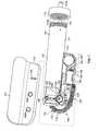
- FIG. 7is an exploded view of a pump device of the infusion pump system of FIG. 1 .
- FIG. 8is an exploded view of a portion of the pump device of the infusion pump system of FIG. 7 .
- FIG. 9is a perspective view of a portion of a drive system of the pump device of FIG. 8 .
- FIG. 10is a perspective view of a portion of a flexible pushrod of the drive system of FIG. 9 .
- FIG. 11is a cross-sectional view of the portion of the drive system of FIG. 9 .
- FIG. 12is a section view of a portion of the pump device of FIG. 8 .
- FIGS. 13A-Bis a perspective view of a portion of a flexible pushrod in accordance with some embodiments.
- FIG. 14is a perspective view of a portion of a flexible pushrod in accordance with some embodiments.
- FIG. 15is a perspective view of a portion of a flexible pushrod in accordance with some embodiments.
- FIG. 16is a perspective view of a portion of a flexible pushrod in accordance with some embodiments.
- FIGS. 17A-Bare perspective views of a portion of the flexible pushrod of FIG. 16 .
- FIG. 18is a perspective view of a flexible pushrod in accordance with some embodiments.
- FIGS. 19-20are perspective views of a flexible pushrod in accordance with some embodiments.
- an infusion pump system 10include a pump device 100 that can communicate with a controller device 200 .
- the pump device 100includes a housing structure 110 that defines a cavity 116 in which a fluid cartridge 120 is received.
- the pump system 10in a medical infusion pump system that is configured to controllably dispense a medicine from the cartridge 120 .
- the fluid cartridge 120may contain a medicine to be infused into the tissue or vasculature of a targeted individual, such as a human or animal patient.
- the pump device 100can be adapted to receive a medicine cartridge 120 in the form of a carpule that is preloaded with insulin or another medicine for use in the treatment of Diabetes (e.g., Byetta®, Symlin®, or others).
- a medicine cartridge 120may be supplied, for example, by Eli Lilly and Co. of Indianapolis, Ind.
- Other examples of medicines contained in the fluid cartridge 120include: pain relief drugs, hormone therapy, blood pressure treatments, anti-emetics, osteoporosis treatments, or other injectable medicines.
- the controller device 200may be removably attached to pump device 100 so that the two components are mechanically mounted to one another. Such a mechanical attachment can secure an electrical connection between the removable controller device 200 and the pump device 100 .
- the controller device 200may be in electrical communication with a portion of a drive system (not shown in FIGS. 1-2 ) of the pump device 100 .
- the pump device 100includes a drive system that causes controlled dispensation of the medicine or other fluid from the cartridge 120 .
- the drive systemincrementally advances a pushrod (refer, for example, to FIG. 7 ) longitudinally into the cartridge 120 so that the fluid is force out of the output end 122 .
- the septum at the output end 122can be pierced to permit fluid outflow when a cap member 115 is connected to the pump housing structure 110 (described in more detail below, for example, in connection with FIG. 5 ).
- the controller device 200communicates electronic control signals via hard-wire-connection to the drive system or other components of the pump device 100 .
- the drive system of the pump device 100causes medicine to incrementally dispense from the medicine cartridge 120 .
- the controller device 200can include a controller housing structure 210 that is configured to mate with a complementary portion of the pump housing structure 110 so as to form a releasable mechanical connection.
- the controller housing structure 210may define a cavity (refer, for example, to FIG. 6 ) that mates with a portion of the pump housing structure 110 for a snap fit engagement.
- the controller housing structure 210may include a finger 212 that engages a mating surface 117 of the pump housing structure 110 when the controller device 200 is removably attached to the pump device 100 .
- a magnetic attachmentmay be employed to releasably secure the pump device 100 .
- the magnetic attachmentcan serve to retain the pump housing structure 110 in the cavity defined by the controller housing structure 210 .
- one or more releasable connector devicese.g., mating tongues and grooves, mounting protrusions friction fit into mating cavities, or the like
- the pump device 100may include one or more electrical contacts (e.g., conductive pads, pins, and the like) that are exposed to the controller device 200 and that mate with complementary electrical contacts on the adjacent face of the controller device 200 .
- the electrical contactsprovide the electrical communication between the control circuitry of the controller device 200 and at least a portion of the drive system or other components of the pump device 100 .
- the electrical contactspermit the transmission electrical control signals to the pump device 100 and the reception of feedback signals (e.g., sensor signals) from particular components within the pump device 100 .
- the controller device 200includes a user interface 220 that permits a user to monitor the operation of the pump device 100 .
- the user interfaceincludes a display 222 and one or more user-selectable buttons (e.g., four buttons 224 a , 224 b , 224 c , and 224 d in this embodiment).
- the display 222may include an active area 223 in which numerals, text, symbols, images, or combination thereof can be displayed.
- the display 222may be used to communicate a number of settings or menu options for the infusion pump system 10 .
- the usermay press one or more of the buttons 224 a , 224 b , 224 c , and 224 d to shuffle through a number of menus or program screens that show particular settings and data (e.g., review data that shows the medicine dispensing rate, the total amount of medicine dispensed in a given time period, the amount of medicine scheduled to be dispensed at a particular time or date, the approximate amount of medicine remaining the cartridge 120 , or the like).
- the usercan adjust the settings or otherwise program the controller device 200 by pressing one or more buttons 224 a , 224 b , 224 c , and 224 d of the user interface 220 .
- the usermay press one or more of the buttons 224 a , 224 b , 224 c , and 224 d to change the dispensation rate of insulin or to request that a bolus of insulin be dispensed immediately or at a scheduled, later time.
- the display 222 of the user interface 220may be configured to display quick reference information when no buttons 224 a , 224 b , 224 c , and 224 d have been pressed.
- the active area 223 of the display 222can display the time embodiments
- the user interface 220may include only one button or may include a numbers of buttons, such as two buttons, three buttons, five buttons, or more.
- the user interface 220 of the controller device 200may include touch screen so that a user may select buttons defined by the active area of the touch screen display.
- the user interfacemay comprise audio inputs or outputs so that a user can monitor the operation of the pump device.
- Previously incorporated U.S. Provisional Application Ser. No. 60/721,267also describes a number of configurations for a removable controller device and a user interface for the device in addition to the configuration illustrated in FIGS. 1-2 herein.
- the infusion pump system 10may be configured to be portable and can be wearable and concealable.
- a usercan conveniently wear the infusion pump system 10 on the user's skin (e.g., skin adhesive) underneath the user's clothing or carry the pump device 100 in the user's pocket (or other portable location) while receiving the medicine dispensed from the pump device 100 .
- the drive systemmay be housed in the housing structure 110 of the pump device 100 in a compact manner so that the pump device 100 has a reduced length.
- the overall length of the pump housing structure 110(which contains medicine cartridge and the drive system) can be about 7 cm to about 9 cm (about 8.3 cm or less in this embodiment).
- the pump housing structure 110may have an overall height of about 1.5 cm to about 4 cm (about 2.9 cm or less in this embodiment) and an overall thickness of about 8 mm to about 20 mm (about 14.5 mm or less in this embodiment).
- the controller device 200can be figured to mate with the compact pump housing 110 so that, when removably attached to one another, the components define a portable infusion pump unit that stores a relatively large quantity of medicine compared to the overall size of the unit.
- the infusion pump system 10(including the pump device 100 attached to the removable controller device 200 ) may have an overall length of about 7 cm to about 9 cm (about 8.5 cm or less in this embodiment), an overall height of about 1.5 cm to about 4 cm (about 3.5 cm or less in and the date for a period of time after no button 224 a , 224 b , 224 c , or 224 d has been actuated (e.g., five seconds, 10 seconds, 30 seconds, 1 minute, 5 minutes, or the like).
- the display 222may enter sleep mode in which the active area 223 is blank, thereby conserving battery power.
- the active areacan display particular device settings, such as the current dispensation rate or the total medicine dispensed, for a period of time after no button 224 a , 224 b , 224 c , or 224 d has been actuated (e.g., five seconds, 10 seconds, 30 seconds, 1 minute, 5 minutes, or the like). Again, thereafter the display 222 may enter sleep mode to conserve battery power.
- the display 222can dim after a first period of time in which no button 224 a , 224 b , 224 c , or 224 d has been actuated (e.g., after 15 seconds or the like), and then the display 22 can enter sleep mode and become blank after a second period of time in which no button 224 a , 224 b , 224 c , or 224 d has been actuated (e.g., after 30 seconds or the like).
- the dimming of the display device 222can alert a user viewing the display device 222 when the active area 223 of the display device will soon become blank.
- the controller device 200when the controller device 200 is connected to the pump device 100 , the user is provided with the opportunity to readily monitor infusion pump operation by simply viewing the user interface 220 connected to the pump device 100 .
- Such monitoring capabilitiesmay provide comfort to a user who may have urgent questions about the current operation of the pump device 100 (e.g., the user may be unable to receive immediate answers if wearing an infusion pump device having no user interface attached thereto).
- the usercan readily operate the user interface 220 removably attached to the pump device 100 , without the requirement of locating and operating a separate monitoring module.
- the user interface 200is not limited to the display and buttons depicted in FIG. 1 .
- this embodiment of the infusion pump system 10is pocket-sized so that the pump device 100 and controller device 200 can be worn in the user's pocket or in another portion of the user's clothing.
- the cap member 115 of the pump device 100may be configured to connect with a flexible tube 119 of an infusion set.
- the infusion setmay include the tube 119 that extends toward a skin adhesive patch and connects with an infusion cannula (not shown in FIG. 3 ).
- the skin adhesive patchcan retain the infusion cannula in fluid communication with the tissue or vasculature of the patient so that the medicine dispensed through the tube 119 passes through the cannula and into the user's body.
- the cap member 115may provide fluid communication between the output end 122 ( FIG. 1 ) of the medicine cartridge 120 and the tube 119 of the infusion set.
- the usercan carry the portable infusion pump system 10 (e.g., in the user's pocket, connected to a belt clip, or adhered to the user's skin) while the tube 119 extends to the location in which the skin is penetrated for infusion. If the user desires to monitor the operation of the pump device 100 or to adjust the settings of the infusion pump system 10 , the user can readily access the user interface 220 of the controller device 200 without the need for carrying and operating a separate module.
- the infusion pump system 10may be configured to adhere to the user's skin directly at the location in which the skin is penetrated for medicine infusion.
- a rear surface 102 of the pump device 100(refer, for example, to FIG. 2 ) may include a skin adhesive patch so that the pump device 100 is physically adhered to the skin of the user at a particular location.
- the cap member 115may have a configuration in which medicine passes directly from the cap member 115 into an infusion cannula that is penetrated into the user's skin.
- the usercan readily access the user interface 220 of the controller device 200 without the need for carrying and operating a second, separate device. For example, the user may look toward the pump device 100 to view the user interface 220 of the controller device 220 that is removably attached thereto.
- the pump device 100 of the infusion pump system 10is configured to removably attached to the controller device 200 .
- the pump device 100includes a pump housing structure 110 , and at least a portion of the pump housing structure 110 is configured to be received in a complementary cavity 215 ( FIG. 5 ) defined in the controller housing structure 210 .
- a retainer finger 212may engage a mating surface of the pump housing structure 110 .
- a magnetic attachmentcan be used to releasably secure the pump device 100 to any of the controller housing structures 210 .
- the pump device 100includes one or more magnetically attractable devices 118 a and 118 b (e.g., permanent magnets in this embodiment depicted in FIG. 4 ) exhibited on the front surface 104 of the pump housing structure 110 which magnetically engage complementary devices 218 a and 218 b (e.g., permanent magnets in this embodiment depicted in FIG. 5 ) arranged on the controller housing structure 210 .
- the magnetically attractable devices 118 a - b and 218 a - bform a magnetic attachment to retain the pump device 100 therein.
- the pump device 100may include one or more electrical contacts 149 that provide electrical communication with one or more components disposed in the pump device 100 .
- the controller device 200may include one or more electrical contacts 249 that provide electrical communication with one or more components disposed in the controller device 200 , such as a controller circuit 240 .
- the electrical contacts 149 of the pump device 100are arranged to engage complementary electrical contacts 249 ( FIG. 5 ) positioned on the controller housing structure 210 .
- the electrical contacts 249are arranged on the controller housing structure 210 so as to align with the electrical contacts 149 of the pump device 100 when the pump device 100 is received in the cavity 215 of the controller device 200 . Accordingly, when the pump device 100 is removably attached to the controller device 200 , the controller device 200 becomes electrically connected to the pump device 100 via the contacts 149 and 249 to provide for the communication of electrical control signals from the controller circuit 240 .
- the controller circuit 240 of the controller device 200may include a battery 245 and a microcontroller device 246 that coordinates the electrical communication to and from the controller device 200 . At least a portion of the controller circuit 240 can be embodied on a printed circuit board (or a flexible circuit substrate). The battery 245 and the microcontroller 246 can be mounted to such a printed circuit board (or connect to such a flexible circuit substrate). Electrical connections from the electrical contacts 249 and the user interface 220 ( FIG. 6 ) may extend along the printed circuit board to the microcontroller device 246 . In this embodiment, the controller circuit 240 is disposed in a hollow space of the controller housing structure 210 .
- the controller housing structure 210can be formed from two molded portions that are welded or adhered to one another after the controller circuit 240 is assembled therein.
- some embodiments of the controller circuit 240may include a cable connector 243 (e.g., a USB connection port or another data cable port).
- a cablemay be connected to the controller circuit 240 to upload data or program settings to the controller circuit or to download data from the controller circuit 240 .
- historical data of medicine deliverycan be downloaded from the controller circuit 240 (via the cable connector 243 ) to a computer system of a physician or a user for purposes of analysis and program adjustments.
- the data cablemay also provide recharging power to the controller circuit 240 .
- the user interface 220 of the controller device 200can include input components, output components, or both that are electrically connected to the controller circuit 240 ( FIG. 5 ).
- the user interfaceincludes a display device 222 having an active area 223 that outputs information to a user and four buttons 224 a , 224 b , 224 c , and 224 d that receive input from the user.
- the display 222may be used to communicate a number of settings or menu options for the infusion pump system 10 .
- the controller circuit 240may receive the input commands from the user's button selection and thereby cause the display device 222 to output a number of menus or program screens that show particular settings and data (e.g., review data that shows the medicine dispensing rate, the total amount of medicine dispensed in a given time period, the amount of medicine scheduled to be dispensed at a particular time or date, the approximate amount of medicine remaining the cartridge 120 , or the like).
- the controller circuit 240can be programmable in that the input commands from the button selections can cause the controller circuit 240 to change any one of a number of settings for the infusion pump system 100 .
- the controller device 200may include an indicia (not shown in FIGS. 4-6 ) that identifies the particular type of medicine cartridge 120 or medicine with which it is to be employed.
- the medicine cartridge 120may include a similar indicia (not shown in FIGS. 4-6 ).
- the usercan verify that the appropriate type of medicine is received in the pump device 100 for controlled dispensation by the controller device 200 .
- the indiciamay include a label, marking, etching, or the like disposed on the controller housing structure 210 that indicates a particular name, code, or other identifier corresponding to a particular medicine 231 (e.g., “EXENATIDE”, “BYETTA”, “INSULIN”, or another identifier).
- the pump device 100 of the infusion pump system 10may include a drive system 105 that is controlled by the removable controller device 200 . Accordingly, the drive system 105 can accurately and incrementally dispense fluid from the pump device 100 in a controlled manner.
- the pump housing structure 110includes a detachable shell 112 that covers at least a portion of the drive system 105 and includes a frame portion 114 to which at least a portion of the drive system 105 is mounted.
- the detachable shell 112may include an inner curved surface against which a curved section of a pushrod 170 rests.
- the detachable shell 112can be part of the pump housing structure 110 that engages with the controller device 200 as previously described in connection with FIGS.
- the detachable shell portion 112may include the magnetically attractable devices 118 a and 118 b that releasably secure the pump device 100 to the controller device 200 .
- the detachable shell 112may provide access to the electrical contacts 149 of the pump device 100 .
- the electrical contacts 149are configured to align with the contact circuit device 148 arranged in the pump device 100 .
- the electrical contacts of the pump device 100can be arranged directly on the contact circuit device 148 , and the detachable shell 112 may include a slot (in the location shown as numeral 149 ) so as to permit electrical engagement with the controller device 200 .
- the detachable shell 112 and the frame portion 114can be molded from polymer material, such as Polycarbonate, Acrylonitrile Butadiene Styrene (ABS), or Acrylic.
- the detachable shell portion 112comprises a generally opaque, moldable material so that the drive system 105 and other components of the pump device are concealed from view.
- the frame portion 114may include a cylindrical receiver 113 that defines the space 116 to receive the medicine cartridge 120 ( FIG. 2 ). In some circumstances, at least a portion of the cylindrical receiver 113 is transparent or translucent so that the user may view the medicine cartridge 120 therein.
- the receiver 113may also include a connector to mate with the cap member 115 .
- the connectorcomprises an external thread pattern formed on the receiver 113 that mates with an internal thread pattern of the cap member 115 . Accordingly, the cap member 115 can be secured to the frame portion 113 after the medicine cartridge 120 ( FIG. 2 ) has been received therein.
- the cap member 115may include a cartridge penetrator 115 a that pierces the output end 122 ( FIG. 2 ) of the medicine cartridge 120 when the cap member 115 is mounted to the frame portion 113 .
- the cartridge penetrator 115 ais in fluid communication with an tube connector 115 b , which can be connected to a tube 119 of an infusion set device (as previously described in connection with FIG. 3 ).
- the fluid cartridge 120may occupy a majority of the length of the pump housing structure 110 (with the drive system 105 being arranged in a compact manner) so that the pump device 100 is wearable and portable.
- some embodiments of the pump device 100include a local pump circuit 140 that includes the contact circuit device 148 .
- the local pump circuit 140may be simple and inexpensive so as to facilitate a low-cost pump device 100 that is disposable.
- the local pump circuit 140may comprise a printed circuit board or a flexible circuit that is arranged in the frame portion 114 of the pump device 100 .
- the local pump circuit 140can include a gateway circuit device 146 that coordinates the transmission of electrical signals to or from the contact circuit device 148 and to or from components of the drive system 105 (e.g., the motor 130 and other components). In some circumstances, the gateway circuit device 146 may be under the control of and directed by the control circuit 240 in the controller device 200 .
- the local pump circuit 140may be configured to operate without the gateway circuit device 146 .
- the control circuit in the removable controller device 200may communicate via the electrical contacts directly with a portion of the drive system 105 (e.g., direct electrical communication with the motor 130 ), with one or more sensors disposed in the pump device 100 , and with other components of the local pump circuit 140 .
- the local pump circuit 140may include a battery 145 that is capable of transmitting electrical energy to the controller device 200 when the pump device 100 is removably attached to the controller device 200 .
- the battery 145 in the pump devicecan be used to recharge the battery 245 ( FIG. 5 ) in the reusable controller device 200 .
- the local pump circuit 140may be electrically connected to one or more sensors disposed in the pump device 100 .
- the gateway circuit device 146 of the circuit 140may be in electrical communication (e.g., via one or more electrical wires or electrically conductive traces) with a force sensor 147 (refer to FIG. 8 ) arranged between the plunger connector 178 that the plunger 121 .
- the force sensor 147may comprise a force transducer or load cell that is capable of electrically communicating an applied force. As such, the force sensor 147 can provide feedback signals to the local pump circuit 140 (or to the control device 200 via the electrical contacts) so as to monitor the force transmitted to the plunger 121 of the medicine cartridge 120 . Such information can be used, for example, to detect if an occlusion exists in the medicine flow path.
- Other sensorse.g., a pressure sensor, a flow sensor, a rotation sensor, a displacement sensor, or the like
- the drive system 105may include a rotational motor 130 that is coupled to a string member 135 , which is used to adjust a ratchet mechanism 150 .
- the ratchet mechanism 150may drive the forward incremental motion of the pushrod 170 so as to dispense medicine from the pump device 100 .
- the drive system 105can provide a reliable and compact configuration for accurately dispensing the desired volume of fluid from the pump device 100 .
- the drive system 105may comprise few, if any, high-cost actuator components or electronics, thereby facilitating the relatively low-cost production of a disposable and reliable pump device 100 .
- the rotational motor 130can be used to act upon the string member 135 , thereby causing the string member 135 to adjust a pawl member 152 relative to a ratchet body 155 (e.g., a ratchet wheel integrally formed on the worm gear 156 in this embodiment).
- the string member 135is configured in a loop arrangement (e.g., looped around pin structures 136 , 137 , 138 , and 139 in this embodiment) so that the string member 135 can be twisted or untwisted in response to the motor rotation.
- the motion path of the string member 135 and the orientation of the string member 135can be configured to provide an efficient mechanical advantage orientation during the desired motion of the adjustable pawl member 152 .
- One of the pin structures 138may be coupled to the adjustable pawl member 152 while the remaining pin structures 136 , 137 , and 139 are coupled to the frame portion 114 of the pump device 100 .
- the motor 130can twist the string to force the pawl member 152 to a reset position.
- the spring device 154can drive the pawl member from the reset position to a forward position (as the string member is untwisted), which incrementally rotates the ratchet wheel 155 .
- a plunger connector 178may be coupled to the leading end of the flexible pushrod 170 so as to abut against or connect with the plunger 121 in the plunger chamber 126 of the fluid cartridge 120 .
- plunger chamber 126e.g., defined in this embodiment by the circumferential wall 124 of the fluid cartridge 120
- the fluid in the cartridge 120is forced from septum at the output end 122 .
- some components of the drive system 105can be retained by the frame portion 114 , a cover mount 107 that is assembled to the frame portion 114 , or a combination thereof.
- the rotational motor 130 , the string member 135 , and the spring device 154can be assembled into the frame portion 114 and then retained by the cover mount 107 .
- the adjustable pawl member 152 , the ratchet wheel 155 , and the worm gear 156can be assembled onto and axle 151 that is integrally formed with the frame portion 114 and then retained by the cover mount 107 .
- a locking pawl 159can be integrally formed with the frame portion 114 so as to align with the ratchet wheel 155 when the ratchet wheel 155 is assembled onto the axle 151 .
- the drive wheel 160 and an adjacent bearing 165can be received in annular channels 163 and 167 , respectively, of the frame portion 114 .
- the cover mount 107can restrict the radial or axial movement of the drive wheel 160 while permitting forward rotation of the drive wheel 160 .
- the “unused” or retracted portion of the pushrod 170may rest in a channel 108 defined in the top of the cover mount 107 .
- the cover mount 107 and the frame portion 114can collectively permit the desired motion of the components of the drive system 105 while reducing the likelihood of “backlash” movement or component dislodgement (which might otherwise occur, for example, when the pump device 100 is dropped to the ground).
- Previously incorporated U.S. Provisional Application Ser. No. 60/720,411also describes a number of configurations for the drive system in addition to the illustrative example depicted in FIG. 8 herein.
- the drive system 105can employ one or more sensors to indicate when the pawl member 152 has reach the reset position or the forward position.
- these sensorscan be optical, magnetic, or contact type sensors.
- the sensorsmay be capable of transmitting signals that indicate when the location of the pin structure 148 or the pawl member 152 is detected. Such sensor signals may be transmitted to the first circuit 140 , to the controller device 200 or 300 , or a combination thereof.
- the pushrod 170may undergo only forward or positive displacement as a result of drive system 105 .
- the drive system 105substantially hinders the pushrod 170 from retracting or “backing up” in response to fluid pressure in the medicine cartridge 120 or other reversal forces.
- the flexible pushrod 170can be retracted only upon disassembly of the pump device 100 (e.g., to disengage the gears or the ratchet mechanism).
- the non-retractable pushrod configurationdue to the drive system 105 ) may facilitate a “one time use” disposable pump device, thereby reducing the likelihood of failure due to non-intended repeated use of the disposable pump device.
- the flexible pushrod 170may comprise a plurality of segments 172 serially connected by hinge portions 175 so that the flexible pushrod 170 is adjustable from a curved shape to a noncurved shape.
- the plurality of segments 172 and the interconnecting hinge portions 175can be integrally formed in one piece from a moldable material, including one or more polymer materials such as Nylon or POM.
- each segment 172is hingedly engaged with the adjacent, neighboring segment 172 .
- each segment 172can pivot away from the adjacent segment 172 so that a portion the flexible pushrod 170 takes on a curved shape.
- each segmentcan pivot toward the adjacent segments so that a front surface or leading face 171 of one segment abuts the rear surface or trailing face 179 of the adjacent segment 179 , thereby forming a generally noncurved shape for a portion of the pushrod 170 .
- that portion of the pushrodcan become a rigid device to transfer a pushing force.
- the plurality of segments 172comprise generally cylindrical segments that each include an thread pattern 176 along at least one cylindrical surface portion 177 ( FIG. 10 ).
- the thread pattern 176can engage a mating thread pattern of the drive wheel 160 .
- the thread pattern 176 of the pushrod segments 172may be an external thread pattern that mates with an internal thread pattern of the drive wheel 160 . Accordingly, the incremental rotation of the drive wheel 160 can be translated into an incremental longitudinal motion for the pushrod 170 .
- Previously incorporated U.S. Provisional Application Ser. No. 60/720,405also describes a number of configurations for the flexible pushrod and the engagement with the drive wheel.
- the flexible pushrod 170can include an anti-rotation mechanism that hinders the pushrod 170 from rotating with drive wheel 160 .
- the anti-rotation mechanismincludes two longitudinal channels 173 and 174 that engage respective protrusions on the frame portion 114 (refer to FIG. 12 ), thereby hindering rotation of the pushrod 170 about its longitudinal axis. Because the drive wheel 160 can rotate relative to the pushrod 170 (which is substantially prevented from rotating by the anti-rotation mechanism), the rotation of the drive wheel 160 can thereby translate into the longitudinal motion of the pushrod 170 .
- the flexible pushrod 170can include a structure that mates with the drive wheel 160 so as to translate the rotation of the drive wheel 160 into a longitudinal motion of the pushrod 170 .
- the pushrod segments 172include an external thread pattern 176 along some or all of the cylindrical surface portion 177 .
- the external thread pattern 176is capable of mating with an internal thread pattern 166 of the drive wheel 160 .
- rotation of the drive wheel 160causes the internal thread pattern 166 to mesh with external thread pattern 176 of the pushrod segment, thereby driving the pushrod segment in a longitudinal direction.
- the thread count and angulation of the thread patterns 166 and 176can be selected to provide predetermined longitudinal advancement distance of the pushrod 170 for a given increment of rotation of the drive wheel 160 .
- the drive system 105can advance the pushrod 170 a longitudinal advancement distance of about 16 microns or less (about 4 microns to about 12 microns, and preferably about 7 microns to about 8 microns) for each incremental motion cycle of the motor 130 , string member 135 , and ratchet mechanism 150 as described herein
- At least a portion of the pushrod 170 that is not yet advanced into engagement with the drive wheel 160may have a curved shaped.
- the hinge portions 175may be flexed so that a first segment 172 is pivoted away from the an adjacent second segment 172 .
- that particular segment 172may hingedly adjust toward the immediately forward segment 172 .
- at least a portion of the pushrod 170 that is advanced through the drive wheel 160may have a generally straight shape (with the forward most segment 172 pressing against the plunger connector 178 ( FIG. 8 ) that presses against the plunger 121 of the medicine cartridge 120 ( FIG. 8 )).
- the leading face 171 of one segment 172can abut the trailing face 179 of the adjacent segment 174 so as to transfer a pushing force.
- the anti-rotation mechanism of the flexible pushrod 170can interact with the frame portion 114 of the pump device 100 so as to hinder rotation of the pushrod 170 during rotation of the drive wheel 160 (removed from FIG. 12 for purposes of illustration; refer to FIG. 8 ).
- the drive wheel 160can rotate about its axis while the anti-rotation mechanism opposes rotation of the pushrod 170 about the longitudinal axis of the pushrod 170 .
- the anti-rotation mechanismcomprises two longitudinal channels 173 and 174 , each of which extend through the pushrod segments 172 in a generally longitudinal direction. As shown in FIG.
- the first longitudinal channel 173can engage a 10 complementary protrusion 111 a on the frame portion 114 proximate the drive wheel 160 (not shown in FIG. 12 ) so that the flexible pushrod 170 is hindered from rotating when the drive wheel 160 turns relative to the frame portion 114 .
- the second longitudinal channel 174can engage a complementary protrusion 111 b on the frame portion 114 proximate the drive wheel so as to further hinder rotation of the pushrod 170 when the drive wheel 160 turns relative to the frame portion 114 .
- each longitudinal channel 173 and 174 in the segment 172aligns to form a keyway that receives a mating key (e.g., the protrusion 111 a or 111 b ) on the frame portion 114 .
- two or more longitudinal channelsmay be employed in an anti-rotation mechanism for the pushrod 170 .
- the channelsmay be configured to have a relatively smaller size while still providing the anti-rotation services.
- the smaller-sized channelsmay permit the pushrod segment 172 to slidably engage the protrusions 111 a and 111 b of the frame member 114 with substantially reduced friction. Such a reduction in the friction upon the pushrod 170 can reduce the overall load imposed upon the drive system 105 of the pump device.
- the anti-rotation mechanismmay include one longitudinal channel, three longitudinal channels, or more longitudinal channels (with each channel capable of engaging an associated protrusion that acts as a key to hinder rotation while permitting longitudinal motion).
- the anti-rotation mechanismmay include one or more flat surfaces along each segment 172 (with the flat surface slidably engaging a complementary flat surface on the frame portion 114 ).
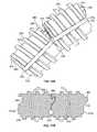
- a flexible pushrod 370 for use in the pump device 100may include an anti-torsion mechanism 380 and, optionally, an anti-rotation mechanism (e.g., at least one longitudinal channel 373 in this embodiment).
- the flexible pushrod 370may comprise a plurality of segments 372 (only two of the segments 372 are shown in FIG. 13 for purposes of illustration) serially connected by hinge portions 375 so that the flexible pushrod 370 is adjustable from a curved shape to a noncurved shape.
- each segment 372can pivot toward or away from the adjacent segment 372 so that a portion the flexible pushrod 370 takes on a curved shape or a noncurved shape.
- the anti-torsion mechanism 380may oppose torsion of one rod segment 372 relative to its adjacent rod segment 372 . By opposing such torsion, the anti-torsion mechanism 380 can resist the torsion across the hinge portions 375 that would otherwise occur from the twisting motion of one segment 372 a relative to the adjacent segment 372 b.
- the plurality of segments 372may comprise a thread pattern 376 along at least one cylindrical surface portion 377 , and the thread pattern 376 is configured to engage a mating thread pattern of the drive wheel (e.g., similar to drive wheel 160 depicted in FIGS. 8 and 11 ). Accordingly, the incremental rotation of the drive wheel 160 ( FIG. 8 ) can be translated into an incremental longitudinal motion for the pushrod 370 . As previously described, when a segment 372 is forwardly advanced through the drive wheel 160 , the segment 372 adjusts toward the immediately forward segment 372 so that a leading face 371 of one segment 372 abuts the trailing face 379 of the adjacent segment 372 .
- the rotation of the drive wheel 160may urge the currently engaged segment 372 a to twist relative to the forward segment 372 b that is substantially rigidly pressed against the piston connector 178 ( FIG. 8 ) and the piston 121 ( FIG. 8 ).
- This twisting bias of the rearward segment 372 s relative to the adjacent forward segment 372 bmay create a torsion (refer, for example, to the illustrative arrows in FIG. 13B ) across the interconnecting hinge portion 375 .
- the pushrod 370may be equipped with an anti-torsion mechanism 380 to resist such relative torsion.
- the anti-torsion mechanism 380can include an extension member (e.g., member 382 ) that extends from one segment into a mating cavity (e.g., cavity 383 ) of the adjacent segment when the two segments are adjusted to a generally straight or rigid condition.
- the anti-torsion mechanism 380may include an integrally formed protrusion 382 that extends from the leading face 371 of a first segment 372 .
- the anti-torsion mechanism 380includes a cavity 383 formed in the trailing face 379 of a second adjacent segment 372 . As shown in FIG.
- the cavity 383is configured to mate with the protrusion 382 when this portion of the pushrod 370 is adjusted to a rigid condition in which the leading face 371 of the first segment 372 a abuts with the trailing face 379 of the adjacent forward segment 372 b.
- Such an engagement of the components of the anti-torsion mechanism 380enables the flexible pushrod 370 to hinder the twisting motion of the first segment 372 a relative to the adjacent segment 372 b .
- the anti-torsion mechanismmay oppose torsion of one rod segment 372 relative to its adjacent rod segment 372 .
- the anti-torsion mechanism 380can resist the torsion across the hinge portions 375 that would otherwise occur from the twisting motion of one segment 372 a relative to the adjacent segment 372 b.
- the flexible pushrod 370can include an anti-rotation mechanism that hinders the pushrod 370 from rotating with drive wheel 160 .
- the anti-rotation mechanismhinders rotation of the pushrod 370 relative to the frame portion 114 (e.g., rotation with the drive wheel 160 )
- the anti-torsion mechanism 380can resist torsion one pushrod segment 372 a relative to an adjacent segment 372 b .
- the anti-rotation mechanismincludes two longitudinal channels (only one channel 373 is shown in the view in FIG. 13A ) that engage respective protrusions on the frame portion 114 (as previously described in connection with FIG. 12 ). Because the drive wheel 160 can rotate relative to the pushrod 370 (which is substantially prevented from rotating by the anti-rotation mechanism), the rotation of the drive wheel 160 can thereby translate into the longitudinal motion of the pushrod 370 .
- some embodiments of the flexible pushrod 370 for use in the pump device 100may include an anti-elongation mechanism 379 to maintain the pushrod segments 372 in an abutting relationship after adjusting to the rigid and generally non-curved shape.
- the anti-elongation mechanism 379may comprise a pressure-sensitive adhesive disposed on the trailing face 379 of the pushrod segments 372 , on the leading face 371 of the pushrod segments 372 , or on both the leading and trailing faces 371 and 379 of the pushrod segments 372 .
- the pushrod segments 372 a and 372 babut against one another and are maintained in the abutted condition by the pressure-sensitive adhesive 389 . Because the segments 372 a and 372 b are urge in the longitudinal direction toward the piston 121 in the medicine cartridge 120 , the pressure between the segments 372 a and 372 b is sufficient to activate the pressure-sensitive adhesive 389 . Also, in some embodiments, the pressure sensitive adhesive may serve as an anti-torsion mechanism that opposes torsion of one rod segment 372 a relative to its adjacent rod segment 372 b.
- Such an engagement of the first segment 372 a relative to the adjacent segment 372 bserves to hinder elongation of the portion of the pushrod 370 that is being forced against the plunger 121 .
- the plunger 121 in the medicine cartridgemay be maintained in a substantially stationary position relative to the pushrod 370 because the pushrod segments 372 a and 372 b are maintained in the rigid and generally non-curved shape. If the portion of the pushrod 370 that is being pushed against the plunger 121 is permitted to elongate (e.g., if the segments 372 a and 372 b in FIG. 13B shift to the disengaged orientation shown in FIG.
- the plunger 121may possibly shift inside the medicine cartridge 120 and incidentally dispense some medicine. Accordingly, the anti-elongation mechanism may maintain of the pushrod segments 372 a and 372 in the abutting relationship after that portion of the pushrod 370 has been adjust to the rigid and generally non-curved shape.
- the anti-elongation mechanismis not limit to the pressure-sensitive adhesive 389 depicted in FIG. 13B .
- the anti-elongation mechanismmay by incorporated into the anti-torsion mechanism 380 ( FIG. 13A ).
- the anti-elongation mechanismmay comprise one or more geometric structures (e.g., a hemispherical extension or the like) that extends from one or both of the lateral sides of the protrusion 382 as to snap into and lock with a mating socket (e.g., a corresponding hemi-sperical socket) defined in the cavity 383 .
- the anti-elongation mechanismmay comprise a pressure sensitive adhesive (like adhesive 389 in FIG.
- anti-elongation mechanismcan maintain of the pushrod segments 372 a and 372 in the abutting relationship after that portion of the pushrod 370 has been adjust to the rigid and generally non-curved shape.
- a flexible pushrod 470 for use in the pump device 100may include hinge portions 475 that are not integral with the material of the pushrod segments 472 .
- the hinge portions 475may comprise a flexible wire that is integrally molded with or assembled into the segments 472 of the pushrod 470 .
- the flexible pushrod 470comprises a plurality of segments 472 (only two of the segments 472 are shown in FIG. 14 for purposes of illustration) serially connected by the hinge portions 475 so that the flexible pushrod 470 is adjustable from a curved shape to a noncurved shape. Because the hinge portions comprise a flexible wire configuration, each segment 472 can pivot toward or away from the adjacent segment 472 so that a portion the flexible pushrod 470 takes on a curved shape or a noncurved shape.
- the plurality of segments 472may comprise a thread pattern 476 along at least one cylindrical surface portion 477 .
- the thread pattern 476is configured to engage a mating thread pattern of the drive wheel (e.g., similar to drive wheel 160 depicted in FIGS. 8 and 11 ). Accordingly, the incremental rotation of the drive wheel 160 ( FIG. 8 ) can be translated into an incremental longitudinal motion for the pushrod 470 .
- the segment 472adjusts toward the immediately forward segment 472 so that a leading face 471 of one segment 472 abuts the trailing face 479 of the adjacent segment 472 .
- the flexible pushrod 470can include an anti-rotation mechanism that hinders the pushrod 470 from rotating with drive wheel 160 ( FIG. 8 ).
- the anti-rotation mechanismincludes two longitudinal channels (only one channel 473 is shown in the view in FIG. 14 ) that engage respective protrusions on the frame portion 114 (as previously described in connection with FIG. 12 ).
- the plurality of segments 472can be formed from a moldable material, including one or more polymer materials such as Nylon or POM.
- a flexible wirecomprising a metallic material (e.g., stainless steel, superelastic Nitinol material, or the like) can be placed into the mold.
- the metallic wirecan be integrally molded with the pushrod segments 472 so as to form a one-piece flexible pushrod 470 .
- the pushrod segments 472are interconnected by hinge portions 475 that include the flexible wire material.
- the hinge portions 475 between the plurality of segments 472 in the pushrodinclude the same flexible wire piece. It should be understood that, in some embodiments, each individual hinge portion may include an individual flexible wire that is separate from other hinge portions 475 of the pushrod 470 .
- the flexible pushrod 470may include an anti-elongation mechanism that maintains of the pushrod segments 472 in an abutting relationship after that portion of the pushrod 470 has been adjust to the rigid and generally non-curved shape.
- the anti-elongation mechanismmay comprise a pressure-sensitive adhesive disposed on the trailing face 479 or leading face 471 of the pushrod segments 472 .
- a flexible pushrod 570 for use in the pump device 100may include hinge portions 575 that include a flexible wire material and may include an anti-torsion mechanism 580 . Similar to embodiments previously described in connection with FIGS. 13A-B , the anti-torsion mechanism 580 may resist the torsion across the hinge portions 575 that would otherwise occur from the twisting motion of one segment 572 relative to the adjacent segment 572 .
- the hinge portions 575comprise a flexible wire that is integrally molded with or assembled into the segments 572 of the pushrod 570 .
- a plurality of the pushrod segments 572(only two of the segments 572 are shown in FIG. 15 for purposes of illustration) serially connected by the hinge portions 575 so that the flexible pushrod 570 is adjustable from a curved shape to a noncurved shape.
- the plurality of segments 572may comprise a thread pattern 576 along at least one cylindrical surface portion 577 .
- the thread pattern 576is configured to engage a mating thread pattern of the drive wheel (e.g., similar to drive wheel 160 depicted in FIGS. 8 and 11 ). Accordingly, the incremental rotation of the drive wheel 160 ( FIG. 8 ) can be translated into an incremental longitudinal motion for the pushrod 570 .
- the pushrod 570may be equipped with an anti-torsion mechanism 580 to resist relative twisting motion between adjacent segments 572 .
- the anti-torsion mechanism 580can include an integrally formed protrusion 582 that extends from the leading face 571 of a first segment 572 .
- the anti-torsion mechanism 580also includes a cavity 583 formed in the trailing face 579 of a second adjacent segment 572 .
- the cavity 583is configured to mate with the protrusion 582 when this portion of the pushrod 570 is adjusted to a rigid condition in which the leading face 571 of the first segment 572 abuts with the trailing face 579 of the adjacent forward segment 572 .
- the anti-torsion mechanism 580may oppose torsion of one rod segment 572 relative to its adjacent rod segment 572 . By opposing such torsion, the anti-torsion mechanism 580 can resist the torsion stresses that might ordinarily occur across the hinge portion 575 .
- the flexible pushrod 570can include an anti-rotation mechanism that hinders the pushrod 570 from rotating with drive wheel 160 ( FIG. 8 ).
- the anti-rotation mechanismincludes two longitudinal channels (only one channel 573 is shown in the view in FIG. 15 ) that engage respective protrusions on the frame portion 114 (as previously described in connection with FIG. 12 ). Because the drive wheel 160 can rotate relative to the pushrod 570 (which is substantially prevented from rotating by the anti-rotation mechanism), the rotation of the drive wheel can thereby translate into the longitudinal motion of the pushrod 570 .
- the flexible pushrod 570may include an anti-elongation mechanism that maintains of the pushrod segments 572 in an abutting relationship after that portion of the pushrod 570 has been adjust to the rigid and generally non-curved shape.
- the anti-elongation mechanismmay comprise a pressure-sensitive adhesive disposed on the trailing face 579 or leading face 571 of the pushrod segments 572 or may be incorporated into the anti-torsion mechanism 580 .
- a flexible pushrod 670 for use in the pump device 100may include hinge portions 690 that can be assembled to interconnect pushrod segments 672 .
- the hinge portions 690may comprise a snap hinge assembly that includes a hinge protrusion 692 ( FIGS. 16 and 17A ) on one segment 672 connectable with a receiver cavity 696 ( FIG. 16 and 17B ) on an adjacent segment 672 .
- the plurality of segments 672(only two of the segments 672 are shown in FIG. 16 for purposes of illustration) serially connected by the respective snap hinge assemblies 690 so that the flexible pushrod 670 is adjustable from a curved shape to a noncurved shape.
- the plurality of segments 672may comprise a thread pattern 676 along at least one cylindrical surface portion 677 .
- the thread pattern 676is configured to engage a mating thread pattern of the drive wheel (e.g., similar to drive wheel 160 depicted in FIGS. 8 and 11 ). Accordingly, the incremental rotation of the drive wheel 160 ( FIG. 8 ) can be translated into an incremental longitudinal motion for the pushrod 670 . Similar to previously described embodiments, when a segment 672 is forwardly advanced through the drive wheel 160 , the segment 672 adjusts toward the immediately forward segment 672 so that a leading face 671 of one segment 672 abuts the trailing face 679 of the adjacent segment 672 .
- the plurality of segments 672can be formed from a moldable material, including one or more polymer materials such as Nylon or POM, and then assembled together using the snap hinge assemblies 690 .
- the hinge protrusion 692 of hinge assembly 690can be inserted into the mating cavity 696 of the adjacent pushrod segment 672 so that the two segments 672 are hingedly engaged with one another.
- the hinge protrusion 692may include an extension body 693 that extends from the leading face 671 of the first pushrod segment 672 .
- locking structures 694 in the form of opposing semi-spherical orbsmay extend laterally from extension body 693 .
- the mating cavity 696 extending into the trailing face 679 of the pushrod segment 672may include sockets 697 therein to receive the locking structures 694 of the hinge protrusion 692 . Accordingly, the hinge protrusion 692 ( FIG. 17A ) can be inserted into the mating cavity 696 ( FIG. 17B ) so that the locking structures 694 snap into engagement with the sockets 697 , thereby providing the hinged coupling between the two segments 672 .
- the pushrod 670may be equipped with an anti-torsion mechanism 680 to resist relative twisting motion between adjacent segments 672 .
- the anti-torsion mechanism 680can include an integrally formed protrusion 682 that extends from the leading face 671 of a first segment 672 .
- the anti-torsion mechanism 680also includes a cavity 683 formed in the trailing face 679 of a second adjacent segment 672 .
- the cavity 683is configured to mate with the protrusion 682 when this portion of the pushrod 670 is adjusted to a rigid condition in which the leading face 671 of the first segment 672 abuts with the trailing face 679 of the adjacent forward segment 672 .
- the anti-torsion mechanism 680may oppose torsion of one rod segment 672 relative to its adjacent rod segment 672 . By opposing such torsion, the anti-torsion mechanism 680 can resist the torsion stresses that might ordinarily occur across the hinge portion 675 .
- the flexible pushrod 670can include an anti-rotation mechanism that hinders the pushrod 670 from rotating with drive wheel 160 ( FIG. 8 ).
- the anti-rotation mechanismincludes two longitudinal channels (only one channel 673 is shown in the view in FIG. 16 ) that engage respective protrusions on the frame portion 114 (as previously described in connection with FIG. 12 ). Because the drive wheel 160 can rotate relative to the pushrod 670 (which is substantially prevented from rotating by the anti-rotation mechanism), the rotation of the drive wheel can thereby translate into the longitudinal motion of the pushrod 670 .
- the flexible pushrod 670may include an anti-elongation mechanism that maintains of the pushrod segments 672 in an abutting relationship after that portion of the pushrod 670 has been adjust to the rigid and generally non-curved shape.
- the anti-elongation mechanismmay comprise a pressure-sensitive adhesive disposed on the trailing face 679 or leading face 671 of the pushrod segments 672 or may be incorporated into the anti-torsion mechanism 680 .
- a flexible pushrod 770 for use in the pump device 100may include an anti-rotation mechanism other than longitudinal channels.
- the flexible pushrod 770may include one or more generally flat lateral faces (e.g., opposing flat faces 773 and 774 are included in this embodiment).
- the generally flat lateral faces 773 and 774can engage complementary flat walls on the frame portion 114 (rather than the protrusions 111 a and 111 b previously described in connection with FIG. 12 ).
- the flexible pushrod 770may comprise a plurality of segments 772 serially connected by hinge portions 775 so that the flexible pushrod 770 is adjustable from a curved shape to a noncurved shape.
- each segment 772can pivot toward or away from the adjacent segment 772 so that a portion the flexible pushrod 770 takes on the curved shape or the noncurved shape.
- the plurality of segments 772may comprise a thread pattern 776 along at least one cylindrical surface portion 777 .
- the thread pattern 776may be configured to engage a mating thread pattern of the drive wheel (e.g., similar to drive wheel 160 depicted in FIGS. 8 and 11 ). Accordingly, the incremental rotation of the drive wheel 160 ( FIG.
- the lateral faces 773 and 774 of the anti-rotation mechanismcan be used to hinder the pushrod 770 from rotating with drive wheel 160 ( FIGS. 8 and 11 ).
- the drive wheel 160can rotate about its axis while the anti-rotation mechanism opposes rotation of the pushrod 770 about the longitudinal axis of the pushrod 770 .
- the lateral faces 773 and 774comprise generally flat lateral sides formed in the thread pattern 776 of each pushrod segment 772 .
- the thread pattern 776 on each segment 772may be discontinuous.
- the generally flat lateral sides formed in the thread pattern 776may be formed into a lateral section of the thread pattern 776 that reaches to the depth of the cylindrical surface portion 777 . Accordingly, in this embodiment, the lateral faces 773 and 774 do not cut substantially into the cylindrical body of the segment 772 , but instead are generally defined along the flat sides of the thread pattern 776 . In such circumstances, the generally flat lateral faces 773 and 774 can engage complementary flat walls on the frame portion 114 (rather than the protrusions 111 a and 111 b previously described in connection with FIG. 12 ). Because the drive wheel 160 ( FIGS.
- the lateral faces 773 and 774may be formed to a depth that cuts into the cylindrical body of the segment 772 and into the thread pattern 776 .
- the flexible pushrod 770can include an anti-torsion mechanism to resist such relative twisting motion between adjacent rod segments 772 .
- the anti-torsion mechanismmay include protrusions that engage mating cavities as previously described in connection with FIGS. 13A-B .
- the anti-torsion mechanism of the flexible pushrod 770can resist the torsion stresses that might ordinarily occur across the hinge portion 775 .
- the flexible pushrod 770may include an anti-elongation mechanism that maintains of the pushrod segments 772 in an abutting relationship after that portion of the pushrod 770 has been adjust to the rigid and generally non-curved shape.
- the anti-elongation mechanismmay comprise a pressure-sensitive adhesive disposed on the trailing face 779 or leading face 771 of the pushrod segments 772 .
- a flexible pushrod 870 for use in the pump device 100may include an anti-rotation mechanism that includes a combination of one or more longitudinal channels and one or more flat lateral side.
- the anti-rotation mechanism of the flexible pushrod 870includes one longitudinal channel 873 and is formed in one generally flat lateral face 874 .
- one or both of the longitudinal channel 873 or the generally flat lateral face 874can engage complementary structure fixed to the frame portion 114 .
- the flexible pushrod 870may comprise a plurality of segments 872 serially connected by hinge portions 875 so that the flexible pushrod 870 is adjustable from a curved shape to a noncurved shape.
- each segment 872can pivot toward or away from the adjacent segment 872 so that a portion the flexible pushrod 870 takes on the curved shape or the noncurved shape.
- the plurality of segments 872may comprise a thread pattern 876 along at least one cylindrical surface portion 877 .
- the thread pattern 876may be configured to engage a mating thread pattern 866 ( FIG. 20 ) of the drive wheel 860 . Accordingly, the incremental rotation of the drive wheel 860 can be translated into an incremental longitudinal motion for the pushrod 870 .
- the drive wheel 860may include a fixed portion 814 that can be mounted to the frame portion 114 of the pump device 100 . Similar to previously described embodiments, when a segment 872 is forwardly advanced through the drive wheel 860 , the segment 872 adjusts toward the immediately forward segment 872 so that a leading face 871 of one segment 872 abuts the trailing face 879 of the adjacent segment 872 .
- one or both of the longitudinal channel 873 or the lateral side 874can be used to hinder the pushrod 870 from rotating with drive wheel 860 .
- the lateral face 874 of the anti-rotation mechanismis formed to a depth that cuts into both the thread pattern 876 and the cylindrical body of each rod segment 872 .
- the thread pattern 876 on each segment 872may be discontinuous.
- the generally flat lateral face 874can engage a complementary flat wall 817 on the fixed portion 814 that is mounted to the frame of the pump device 100 .
- the longitudinal channel 873 of the anti-rotation mechanismcan engage protrusion 811 a on the fixed portion 814 (mounted to the frame of the pump device 100 ).
- the flexible pushrod 870may include two opposing longitudinal channels 873 that are formed respectively in two opposing lateral faces 874 .
- the flexible pushrod 870can include an anti-torsion mechanism to resist such relative twisting motion between adjacent rod segments 872 .
- the anti-torsion mechanismmay include protrusions that engage mating cavities as previously described in connection with FIGS. 13A-B .
- the anti-torsion mechanism of the flexible pushrod 870can resist the torsion stresses that might ordinarily occur across the hinge portion 875 .
- the flexible pushrod 870may include an anti-elongation mechanism that maintains of the pushrod segments 872 in an abutting relationship after that portion of the pushrod 870 has been adjust to the rigid and generally non-curved shape.
- the anti-elongation mechanismmay comprise a pressure-sensitive adhesive disposed on the trailing face 879 or leading face 871 of the pushrod segments 872 .
Landscapes
- Health & Medical Sciences (AREA)
- Vascular Medicine (AREA)
- Engineering & Computer Science (AREA)
- Anesthesiology (AREA)
- Biomedical Technology (AREA)
- Heart & Thoracic Surgery (AREA)
- Hematology (AREA)
- Life Sciences & Earth Sciences (AREA)
- Animal Behavior & Ethology (AREA)
- General Health & Medical Sciences (AREA)
- Public Health (AREA)
- Veterinary Medicine (AREA)
- Infusion, Injection, And Reservoir Apparatuses (AREA)
Abstract
Description
Claims (51)
Priority Applications (11)
| Application Number | Priority Date | Filing Date | Title |
|---|---|---|---|
| US11/522,836US8105279B2 (en) | 2005-09-26 | 2006-09-18 | Dispensing fluid from an infusion pump system |
| US11/677,706US8057436B2 (en) | 2005-09-26 | 2007-02-22 | Dispensing fluid from an infusion pump system |
| US11/677,743US8409142B2 (en) | 2005-09-26 | 2007-02-22 | Operating an infusion pump system |
| US13/009,644US8622966B2 (en) | 2005-09-26 | 2011-01-19 | Operating an infusion pump system |
| US13/251,865US8551046B2 (en) | 2006-09-18 | 2011-10-03 | Dispensing fluid from an infusion pump system |
| US13/358,330US8747368B2 (en) | 2005-09-26 | 2012-01-25 | Dispensing fluid from an infusion pump system |
| US13/361,361US8747369B2 (en) | 2005-09-26 | 2012-01-30 | Dispensing fluid from an infusion pump system |
| US14/146,885US9539388B2 (en) | 2005-09-26 | 2014-01-03 | Operating an infusion pump system |
| US14/299,177US10064993B2 (en) | 2005-09-26 | 2014-06-09 | Dispensing fluid from an infusion pump system |
| US15/370,279US9872957B2 (en) | 2005-09-26 | 2016-12-06 | Operating an infusion pump system |
| US15/850,355US10307536B2 (en) | 2005-09-26 | 2017-12-21 | Operating an infusion pump system |
Applications Claiming Priority (4)
| Application Number | Priority Date | Filing Date | Title |
|---|---|---|---|
| US72041105P | 2005-09-26 | 2005-09-26 | |
| US72040505P | 2005-09-26 | 2005-09-26 | |
| US72126705P | 2005-09-28 | 2005-09-28 | |
| US11/522,836US8105279B2 (en) | 2005-09-26 | 2006-09-18 | Dispensing fluid from an infusion pump system |
Related Child Applications (4)
| Application Number | Title | Priority Date | Filing Date |
|---|---|---|---|
| US11/522,560Continuation-In-PartUS7534226B2 (en) | 2005-09-26 | 2006-09-18 | Dispensing fluid from an infusion pump system |
| US11/677,706Continuation-In-PartUS8057436B2 (en) | 2005-09-26 | 2007-02-22 | Dispensing fluid from an infusion pump system |
| US11/677,743Continuation-In-PartUS8409142B2 (en) | 2005-09-26 | 2007-02-22 | Operating an infusion pump system |
| US13/358,330DivisionUS8747368B2 (en) | 2005-09-26 | 2012-01-25 | Dispensing fluid from an infusion pump system |
Publications (2)
| Publication Number | Publication Date |
|---|---|
| US20070073236A1 US20070073236A1 (en) | 2007-03-29 |
| US8105279B2true US8105279B2 (en) | 2012-01-31 |
Family
ID=37895094
Family Applications (4)
| Application Number | Title | Priority Date | Filing Date |
|---|---|---|---|
| US11/522,836Active2030-09-04US8105279B2 (en) | 2005-09-26 | 2006-09-18 | Dispensing fluid from an infusion pump system |
| US13/358,330Active2026-09-24US8747368B2 (en) | 2005-09-26 | 2012-01-25 | Dispensing fluid from an infusion pump system |
| US13/361,361Active2026-09-24US8747369B2 (en) | 2005-09-26 | 2012-01-30 | Dispensing fluid from an infusion pump system |
| US14/299,177Active2028-06-04US10064993B2 (en) | 2005-09-26 | 2014-06-09 | Dispensing fluid from an infusion pump system |
Family Applications After (3)
| Application Number | Title | Priority Date | Filing Date |
|---|---|---|---|
| US13/358,330Active2026-09-24US8747368B2 (en) | 2005-09-26 | 2012-01-25 | Dispensing fluid from an infusion pump system |
| US13/361,361Active2026-09-24US8747369B2 (en) | 2005-09-26 | 2012-01-30 | Dispensing fluid from an infusion pump system |
| US14/299,177Active2028-06-04US10064993B2 (en) | 2005-09-26 | 2014-06-09 | Dispensing fluid from an infusion pump system |
Country Status (1)
| Country | Link |
|---|---|
| US (4) | US8105279B2 (en) |
Cited By (92)
| Publication number | Priority date | Publication date | Assignee | Title |
|---|---|---|---|---|
| US20080196762A1 (en)* | 2002-07-19 | 2008-08-21 | Scott Mallett | Systems and methods for the accurate delivery of flow materials |
| US20100079360A1 (en)* | 2008-09-30 | 2010-04-01 | Animas Corporation | Medical Devices Using Bistable Displays |
| US20120220936A1 (en)* | 2007-09-07 | 2012-08-30 | Asante Solutions, Inc. | Data Storage for an Infusion Pump System |
| US8287495B2 (en) | 2009-07-30 | 2012-10-16 | Tandem Diabetes Care, Inc. | Infusion pump system with disposable cartridge having pressure venting and pressure feedback |
| US8333717B1 (en) | 2011-06-21 | 2012-12-18 | Yofimeter, Llc | Test unit cartridge for analyte testing device |
| USD679001S1 (en)* | 2011-06-15 | 2013-03-26 | Nigel Kelly | Micro dispensing pump |
| US20130190683A1 (en)* | 2009-12-30 | 2013-07-25 | Medtronic Minimed, Inc. | Connection and alignment detection systems and methods |
| WO2014015239A1 (en)* | 2012-07-19 | 2014-01-23 | Asante Solutions, Inc. | Infusion pump system and method |
| US8852152B2 (en) | 2011-02-09 | 2014-10-07 | Asante Solutions, Inc. | Infusion pump systems and methods |
| US20140358113A1 (en)* | 2005-09-26 | 2014-12-04 | Asante Solutions, Inc. | Dispensing Fluid from an Infusion Pump System |
| US8961432B2 (en) | 2011-06-21 | 2015-02-24 | Yofimeter, Llc | Analyte testing devices |
| US9008803B2 (en) | 2007-05-24 | 2015-04-14 | Tandem Diabetes Care, Inc. | Expert system for insulin pump therapy |
| US9039659B2 (en) | 2009-12-30 | 2015-05-26 | Medtronic Minimed, Inc. | Connection and alignment systems and methods |
| US9072827B2 (en) | 2012-03-26 | 2015-07-07 | Medimop Medical Projects Ltd. | Fail safe point protector for needle safety flap |
| US20150190577A1 (en)* | 2012-09-26 | 2015-07-09 | Gadlight, Inc. | Portable medicine injection device and analyte metering system |
| US9149575B2 (en) | 2010-01-19 | 2015-10-06 | Medimop Medical Projects Ltd. | Needle assembly for drug pump |
| US9166313B2 (en) | 2013-04-30 | 2015-10-20 | Medimop Medical Projects | Power supply contact for installation of printed circuit board |
| US9173997B2 (en) | 2007-10-02 | 2015-11-03 | Medimop Medical Projects Ltd. | External drug pump |
| USD747456S1 (en)* | 2012-12-07 | 2016-01-12 | Becton, Dickinson And Company | Infusion set assembly |
| USD747457S1 (en)* | 2012-12-07 | 2016-01-12 | Becton, Dickinson And Company | Infusion set needle guard |
| USD747458S1 (en)* | 2012-12-07 | 2016-01-12 | Becton, Dickinson And Company | Infusion set insertion needle assembly |
| USD747459S1 (en)* | 2012-12-07 | 2016-01-12 | Becton, Dickinson And Company | Infusion set assembly |
| USD747799S1 (en) | 2011-03-22 | 2016-01-19 | Medimop Medical Projects Ltd. | Cartridge |
| US9259532B2 (en) | 2010-01-19 | 2016-02-16 | Medimop Medical Projects Ltd. | Cartridge interface assembly |
| USD754843S1 (en)* | 2012-12-07 | 2016-04-26 | Becton, Dickinson And Company | Infusion set assembly |
| USD754842S1 (en)* | 2012-12-07 | 2016-04-26 | Becton, Dickinson And Company | Infusion set needle guard |
| USD756504S1 (en)* | 2012-12-07 | 2016-05-17 | Becton, Dickinson And Company | Infusion set base |
| US9345836B2 (en) | 2007-10-02 | 2016-05-24 | Medimop Medical Projects Ltd. | Disengagement resistant telescoping assembly and unidirectional method of assembly for such |
| US9393363B2 (en) | 2009-09-02 | 2016-07-19 | Medtronic Minimed, Inc. | Insertion device systems and methods |
| US9421321B2 (en) | 2009-12-30 | 2016-08-23 | Medtronic Minimed, Inc. | Connection and alignment systems and methods |
| US9421323B2 (en) | 2013-01-03 | 2016-08-23 | Medimop Medical Projects Ltd. | Door and doorstop for portable one use drug delivery apparatus |
| US9452261B2 (en) | 2010-05-10 | 2016-09-27 | Medimop Medical Projects Ltd. | Low volume accurate injector |
| US9463280B2 (en) | 2012-03-26 | 2016-10-11 | Medimop Medical Projects Ltd. | Motion activated septum puncturing drug delivery device |
| US9518813B2 (en) | 2009-12-30 | 2016-12-13 | Medtronic Minimed, Inc. | Sensing systems and methods |
| US9572926B2 (en) | 2009-09-15 | 2017-02-21 | Medimop Medical Projects Ltd. | Cartridge insertion assembly |
| US9656019B2 (en) | 2007-10-02 | 2017-05-23 | Medimop Medical Projects Ltd. | Apparatuses for securing components of a drug delivery system during transport and methods of using same |
| US9744297B2 (en) | 2015-04-10 | 2017-08-29 | Medimop Medical Projects Ltd. | Needle cannula position as an input to operational control of an injection device |
| US9795534B2 (en) | 2015-03-04 | 2017-10-24 | Medimop Medical Projects Ltd. | Compliant coupling assembly for cartridge coupling of a drug delivery device |
| US9795777B2 (en) | 2011-12-07 | 2017-10-24 | Becton, Dickinson And Company | Infusion device with releasable fluid connector |
| USD806233S1 (en)* | 2016-09-09 | 2017-12-26 | Liebel-Flarsheim Company Llc | Powerhead for a power injection system |
| US9889255B2 (en) | 2011-12-07 | 2018-02-13 | Becton, Dickinson And Company | Needle shielding assemblies and infusion devices for use therewith |
| US9889256B2 (en) | 2013-05-03 | 2018-02-13 | Medimop Medical Projects Ltd. | Sensing a status of an infuser based on sensing motor control and power input |
| US9943332B2 (en) | 2009-09-02 | 2018-04-17 | Medtronic Minimed, Inc. | Insertion device systems and methods |
| US9962486B2 (en) | 2013-03-14 | 2018-05-08 | Tandem Diabetes Care, Inc. | System and method for detecting occlusions in an infusion pump |
| US9987432B2 (en) | 2015-09-22 | 2018-06-05 | West Pharma. Services IL, Ltd. | Rotation resistant friction adapter for plunger driver of drug delivery device |
| US9987428B2 (en) | 2011-10-14 | 2018-06-05 | Amgen Inc. | Injector and method of assembly |
| US9993595B2 (en) | 2015-05-18 | 2018-06-12 | Tandem Diabetes Care, Inc. | Patch pump cartridge attachment |
| US10016559B2 (en) | 2009-12-04 | 2018-07-10 | Smiths Medical Asd, Inc. | Advanced step therapy delivery for an ambulatory infusion pump and system |
| US10071198B2 (en) | 2012-11-02 | 2018-09-11 | West Pharma. Servicees IL, Ltd. | Adhesive structure for medical device |
| US10071196B2 (en) | 2012-05-15 | 2018-09-11 | West Pharma. Services IL, Ltd. | Method for selectively powering a battery-operated drug-delivery device and device therefor |
| US10149943B2 (en) | 2015-05-29 | 2018-12-11 | West Pharma. Services IL, Ltd. | Linear rotation stabilizer for a telescoping syringe stopper driverdriving assembly |
| USD838359S1 (en)* | 2016-09-21 | 2019-01-15 | Amgen Inc. | On-body injector |
| US10251813B2 (en) | 2015-03-04 | 2019-04-09 | West Pharma. Services IL, Ltd. | Flexibly mounted cartridge alignment collar for drug delivery device |
| US10258736B2 (en) | 2012-05-17 | 2019-04-16 | Tandem Diabetes Care, Inc. | Systems including vial adapter for fluid transfer |
| US10279106B1 (en) | 2014-05-08 | 2019-05-07 | Tandem Diabetes Care, Inc. | Insulin patch pump |
| US10293120B2 (en) | 2015-04-10 | 2019-05-21 | West Pharma. Services IL, Ltd. | Redundant injection device status indication |
| US10335545B2 (en) | 2012-01-31 | 2019-07-02 | West Pharma. Services IL, Ltd. | Time dependent drug delivery apparatus |
| US10420880B2 (en) | 2007-10-02 | 2019-09-24 | West Pharma. Services IL, Ltd. | Key for securing components of a drug delivery system during assembly and/or transport and methods of using same |
| US20190341137A1 (en)* | 2018-05-07 | 2019-11-07 | Medtronic Minimed, Inc. | Proactive image-based infusion device delivery adjustments |
| USD866375S1 (en) | 2017-08-02 | 2019-11-12 | Buoy Labs, Inc. | Water flow monitoring device |
| US10569016B2 (en) | 2015-12-29 | 2020-02-25 | Tandem Diabetes Care, Inc. | System and method for switching between closed loop and open loop control of an ambulatory infusion pump |
| US10668213B2 (en) | 2012-03-26 | 2020-06-02 | West Pharma. Services IL, Ltd. | Motion activated mechanisms for a drug delivery device |
| US10704935B2 (en) | 2016-12-04 | 2020-07-07 | Buoy Labs, Inc. | Fluid flow detector with tethered drag block |
| US10850037B2 (en) | 2013-03-22 | 2020-12-01 | Amgen Inc. | Injector and method of assembly |
| US10857287B2 (en) | 2017-01-06 | 2020-12-08 | Trustees Of Boston University | Infusion system and components thereof |
| US10881789B2 (en) | 2013-10-24 | 2021-01-05 | Trustees Of Boston University | Infusion system for preventing mischanneling of multiple medicaments |
| US11097055B2 (en) | 2013-10-24 | 2021-08-24 | Amgen Inc. | Injector and method of assembly |
| US11147916B2 (en) | 2015-08-20 | 2021-10-19 | Tandem Diabetes Care, Inc. | Drive mechanism for infusion pump |
| US11167086B2 (en) | 2008-09-15 | 2021-11-09 | West Pharma. Services IL, Ltd. | Stabilized pen injector |
| US20210379289A1 (en)* | 2017-12-08 | 2021-12-09 | Eli Lilly And Company | Medical delivery device with axially expandable drive ribbon |
| US11278661B2 (en) | 2020-03-10 | 2022-03-22 | Beta Bionics, Inc. | Infusion system and components thereof |
| US11291763B2 (en) | 2007-03-13 | 2022-04-05 | Tandem Diabetes Care, Inc. | Basal rate testing using frequent blood glucose input |
| US11298053B2 (en) | 2007-05-30 | 2022-04-12 | Tandem Diabetes Care, Inc. | Insulin pump based expert system |
| US11311674B2 (en) | 2016-01-21 | 2022-04-26 | West Pharma. Services IL, Ltd. | Medicament delivery device comprising a visual indicator |
| US11318254B2 (en) | 2015-10-09 | 2022-05-03 | West Pharma. Services IL, Ltd. | Injector needle cap remover |
| US11331463B2 (en) | 2015-07-08 | 2022-05-17 | Trustees Of Boston University | Infusion system and components thereof |
| US11338090B2 (en) | 2016-08-01 | 2022-05-24 | West Pharma. Services IL, Ltd. | Anti-rotation cartridge pin |
| US11364337B2 (en) | 2016-01-21 | 2022-06-21 | West Pharma. Services IL, Ltd. | Force containment in an automatic injector |
| US11389597B2 (en) | 2016-03-16 | 2022-07-19 | West Pharma. Services IL, Ltd. | Staged telescopic screw assembly having different visual indicators |
| US11458246B2 (en) | 2018-02-05 | 2022-10-04 | Tandem Diabetes Care, Inc. | Methods and systems for detecting infusion pump conditions |
| US11497850B2 (en) | 2009-12-30 | 2022-11-15 | Medtronic Minimed, Inc. | Connection and alignment detection systems and methods |
| US11547802B2 (en) | 2015-10-09 | 2023-01-10 | West Pharma. Services IL, Ltd. | Angled syringe patch injector |
| US11571507B2 (en) | 2019-07-16 | 2023-02-07 | Beta Bionics, Inc. | Ambulatory device and components thereof |
| US11672904B2 (en) | 2016-01-21 | 2023-06-13 | West Pharma. Services IL, Ltd. | Needle insertion and retraction mechanism |
| US11730892B2 (en) | 2016-08-01 | 2023-08-22 | West Pharma. Services IL, Ltd. | Partial door closure prevention spring |
| US11781895B2 (en) | 2018-02-23 | 2023-10-10 | Buoy Labs, Inc. | Fluid flow analysis and management |
| US11819673B2 (en) | 2016-06-02 | 2023-11-21 | West Pharma. Services, IL, Ltd. | Three position needle retraction |
| US11819666B2 (en) | 2017-05-30 | 2023-11-21 | West Pharma. Services IL, Ltd. | Modular drive train for wearable injector |
| US11857767B2 (en) | 2017-12-22 | 2024-01-02 | West Pharma. Services IL, Ltd. | Injector usable with different dimension cartridges |
| US11931552B2 (en) | 2015-06-04 | 2024-03-19 | West Pharma Services Il, Ltd. | Cartridge insertion for drug delivery device |
| USD1031975S1 (en) | 2020-03-10 | 2024-06-18 | Beta Bionics, Inc. | Medicament infusion pump device |
| US12097357B2 (en) | 2008-09-15 | 2024-09-24 | West Pharma. Services IL, Ltd. | Stabilized pen injector |
Families Citing this family (112)
| Publication number | Priority date | Publication date | Assignee | Title |
|---|---|---|---|---|
| AU2003245872A1 (en) | 2002-07-24 | 2004-02-09 | M 2 Medical A/S | An infusion pump system, an infusion pump unit and an infusion pump |
| US20050160858A1 (en)* | 2002-07-24 | 2005-07-28 | M 2 Medical A/S | Shape memory alloy actuator |
| WO2004056412A2 (en) | 2002-12-23 | 2004-07-08 | M2 Medical A/S | A disposable, wearable insulin dispensing device, a combination of such a device and a programming controller and a method of controlling the operation of such a device |
| CN1726059A (en)* | 2002-11-05 | 2006-01-25 | M2医药有限公司 | Disposable wearable insulin dispensing device, combination of the device and a program controller and method for controlling the operation of the device |
| AU2003291963A1 (en)* | 2002-12-23 | 2004-07-14 | M 2 Medical A/S | Flexible piston rod |
| WO2004094823A2 (en) | 2003-04-23 | 2004-11-04 | Biovalve Technologies, Inc. | Hydraulically actuated pump for long duration medicament administration |
| US7753879B2 (en)* | 2004-01-29 | 2010-07-13 | M2 Group Holdings, Inc. | Disposable medicine dispensing device |
| US9089636B2 (en) | 2004-07-02 | 2015-07-28 | Valeritas, Inc. | Methods and devices for delivering GLP-1 and uses thereof |
| EP1877115A1 (en) | 2005-04-06 | 2008-01-16 | M 2 Medical A/S | An actuator |
| US7905868B2 (en)* | 2006-08-23 | 2011-03-15 | Medtronic Minimed, Inc. | Infusion medium delivery device and method with drive device for driving plunger in reservoir |
| US8551046B2 (en) | 2006-09-18 | 2013-10-08 | Asante Solutions, Inc. | Dispensing fluid from an infusion pump system |
| US8057436B2 (en)* | 2005-09-26 | 2011-11-15 | Asante Solutions, Inc. | Dispensing fluid from an infusion pump system |
| DK1933902T3 (en) | 2005-09-26 | 2015-03-23 | Asante Solutions Inc | Infusion Pump WITH A DRIVE THAT HAVE AN PALLEGEME- AND CONGEST HAGE-COMBINATION |
| US7534226B2 (en) | 2005-09-26 | 2009-05-19 | M2 Group Holdings, Inc. | Dispensing fluid from an infusion pump system |
| US8409142B2 (en)* | 2005-09-26 | 2013-04-02 | Asante Solutions, Inc. | Operating an infusion pump system |
| WO2007056592A2 (en) | 2005-11-08 | 2007-05-18 | M2 Medical A/S | Method and system for manual and autonomous control of an infusion pump |
| US8475408B2 (en)* | 2005-11-08 | 2013-07-02 | Asante Solutions, Inc. | Infusion pump system |
| WO2007115039A2 (en) | 2006-03-30 | 2007-10-11 | Valeritas, Llc | Multi-cartridge fluid delivery device |
| ES2973440T3 (en) | 2007-04-10 | 2024-06-20 | Hoffmann La Roche | Apparatus and procedure for pumping fluid |
| US20080269673A1 (en)* | 2007-04-27 | 2008-10-30 | Animas Corporation | Cellular-Enabled Medical Monitoring and Infusion System |
| US7833196B2 (en) | 2007-05-21 | 2010-11-16 | Asante Solutions, Inc. | Illumination instrument for an infusion pump |
| US7892199B2 (en)* | 2007-05-21 | 2011-02-22 | Asante Solutions, Inc. | Occlusion sensing for an infusion pump |
| US7794426B2 (en) | 2007-05-21 | 2010-09-14 | Asante Solutions, Inc. | Infusion pump system with contamination-resistant features |
| US7981102B2 (en) | 2007-05-21 | 2011-07-19 | Asante Solutions, Inc. | Removable controller for an infusion pump |
| US7717903B2 (en) | 2007-09-06 | 2010-05-18 | M2 Group Holdings, Inc. | Operating an infusion pump system |
| US7828528B2 (en)* | 2007-09-06 | 2010-11-09 | Asante Solutions, Inc. | Occlusion sensing system for infusion pumps |
| US7935076B2 (en) | 2007-09-07 | 2011-05-03 | Asante Solutions, Inc. | Activity sensing techniques for an infusion pump system |
| US8287514B2 (en) | 2007-09-07 | 2012-10-16 | Asante Solutions, Inc. | Power management techniques for an infusion pump system |
| US7879026B2 (en) | 2007-09-07 | 2011-02-01 | Asante Solutions, Inc. | Controlled adjustment of medicine dispensation from an infusion pump device |
| US7934912B2 (en)* | 2007-09-27 | 2011-05-03 | Curlin Medical Inc | Peristaltic pump assembly with cassette and mounting pin arrangement |
| US8083503B2 (en)* | 2007-09-27 | 2011-12-27 | Curlin Medical Inc. | Peristaltic pump assembly and regulator therefor |
| US8062008B2 (en)* | 2007-09-27 | 2011-11-22 | Curlin Medical Inc. | Peristaltic pump and removable cassette therefor |
| US7875022B2 (en)* | 2007-12-12 | 2011-01-25 | Asante Solutions, Inc. | Portable infusion pump and media player |
| US8234126B1 (en) | 2008-02-12 | 2012-07-31 | Asante Solutions, Inc. | Distribution of infusion pumps |
| US7938797B2 (en)* | 2008-05-05 | 2011-05-10 | Asante Solutions, Inc. | Infusion pump system |
| DK2276524T3 (en)* | 2008-05-07 | 2012-04-23 | Hoffmann La Roche | View in connection with an infusion management facility |
| US7959598B2 (en)* | 2008-08-20 | 2011-06-14 | Asante Solutions, Inc. | Infusion pump systems and methods |
| US8287487B2 (en) | 2008-10-15 | 2012-10-16 | Asante Solutions, Inc. | Infusion pump system and methods |
| US8974439B2 (en)* | 2009-01-02 | 2015-03-10 | Asante Solutions, Inc. | Infusion pump system and methods |
| US20100217233A1 (en)* | 2009-02-20 | 2010-08-26 | Ranft Elizabeth A | Method and device to anesthetize an area |
| US8308679B2 (en)* | 2009-12-30 | 2012-11-13 | Medtronic Minimed, Inc. | Alignment systems and methods |
| US8858500B2 (en)* | 2009-12-30 | 2014-10-14 | Medtronic Minimed, Inc. | Engagement and sensing systems and methods |
| US9039653B2 (en)* | 2009-12-29 | 2015-05-26 | Medtronic Minimed, Inc. | Retention systems and methods |
| US8998858B2 (en)* | 2009-12-29 | 2015-04-07 | Medtronic Minimed, Inc. | Alignment and connection systems and methods |
| US10030647B2 (en)* | 2010-02-25 | 2018-07-24 | Hayward Industries, Inc. | Universal mount for a variable speed pump drive user interface |
| USD669165S1 (en) | 2010-05-27 | 2012-10-16 | Asante Solutions, Inc. | Infusion pump |
| USD669166S1 (en) | 2010-05-27 | 2012-10-16 | Asante Solutions, Inc. | Infusion pump unit |
| USD669167S1 (en) | 2010-05-27 | 2012-10-16 | Asante Solutions, Inc. | Controller for an infusion pump |
| US9498573B2 (en) | 2010-09-24 | 2016-11-22 | Perqflo, Llc | Infusion pumps |
| US9381300B2 (en) | 2010-09-24 | 2016-07-05 | Perqflo, Llc | Infusion pumps |
| US9216249B2 (en) | 2010-09-24 | 2015-12-22 | Perqflo, Llc | Infusion pumps |
| US8915879B2 (en) | 2010-09-24 | 2014-12-23 | Perqflo, Llc | Infusion pumps |
| US8905972B2 (en) | 2010-11-20 | 2014-12-09 | Perqflo, Llc | Infusion pumps |
| US8585657B2 (en) | 2011-06-21 | 2013-11-19 | Asante Solutions, Inc. | Dispensing fluid from an infusion pump system |
| US8808230B2 (en) | 2011-09-07 | 2014-08-19 | Asante Solutions, Inc. | Occlusion detection for an infusion pump system |
| CN103127579B (en) | 2011-11-21 | 2017-06-16 | 上海泽生科技开发股份有限公司 | The drive system of portable injection pump |
| CN204910157U (en) | 2012-03-05 | 2015-12-30 | 贝克顿·迪金森公司 | System for be used for at body liquid conveying |
| EP4406568A3 (en) | 2012-03-30 | 2024-10-16 | Insulet Corporation | Fluid delivery device with transcutaneous access tool, insertion mechanism and blood glucose monitoring for use therewith |
| KR101666290B1 (en)* | 2012-04-10 | 2016-10-24 | 케어베이 유럽 리미티드 | Infusion device |
| US9950118B2 (en) | 2012-04-20 | 2018-04-24 | Novo Nordisk A/S | Medical injection device comprising a secondary safety limiter |
| US8454562B1 (en) | 2012-07-20 | 2013-06-04 | Asante Solutions, Inc. | Infusion pump system and method |
| US9901677B2 (en) | 2012-10-16 | 2018-02-27 | Bigfoot Biomedical, Inc. | Infusion pump system and methods |
| US9427523B2 (en) | 2012-12-10 | 2016-08-30 | Bigfoot Biomedical, Inc. | Infusion pump system and method |
| US20140276536A1 (en) | 2013-03-14 | 2014-09-18 | Asante Solutions, Inc. | Infusion Pump System and Methods |
| US9446186B2 (en) | 2013-03-01 | 2016-09-20 | Bigfoot Biomedical, Inc. | Operating an infusion pump system |
| USD711872S1 (en)* | 2013-03-15 | 2014-08-26 | Samsung Electronics Co., Ltd. | Electronic device |
| US9457141B2 (en) | 2013-06-03 | 2016-10-04 | Bigfoot Biomedical, Inc. | Infusion pump system and method |
| US9446187B2 (en) | 2013-06-03 | 2016-09-20 | Bigfoot Biomedical, Inc. | Infusion pump system and method |
| US9561324B2 (en) | 2013-07-19 | 2017-02-07 | Bigfoot Biomedical, Inc. | Infusion pump system and method |
| TWI569832B (en) | 2013-10-23 | 2017-02-11 | 卡貝歐洲有限公司 | Medicament delivery device |
| US10569015B2 (en) | 2013-12-02 | 2020-02-25 | Bigfoot Biomedical, Inc. | Infusion pump system and method |
| US9629901B2 (en) | 2014-07-01 | 2017-04-25 | Bigfoot Biomedical, Inc. | Glucagon administration system and methods |
| US10137246B2 (en) | 2014-08-06 | 2018-11-27 | Bigfoot Biomedical, Inc. | Infusion pump assembly and method |
| US9919096B2 (en) | 2014-08-26 | 2018-03-20 | Bigfoot Biomedical, Inc. | Infusion pump system and method |
| US11464899B2 (en) | 2014-08-28 | 2022-10-11 | Becton, Dickinson And Company | Wireless communication for on-body medical devices |
| US10159786B2 (en) | 2014-09-30 | 2018-12-25 | Perqflo, Llc | Hybrid ambulatory infusion pumps |
| US12178992B2 (en) | 2014-09-30 | 2024-12-31 | Medtronic Minimed, Inc. | Different disposable assemblies for the same reusable assembly |
| EP3204070B1 (en)* | 2014-10-07 | 2020-12-02 | Silgan Dispensing Systems Corporation | Indexing dose dispensing device |
| US10737016B2 (en) | 2015-02-18 | 2020-08-11 | Medtronic Minimed, Inc. | Ambulatory infusion pumps and reservoir assemblies for use with same |
| US9878097B2 (en) | 2015-04-29 | 2018-01-30 | Bigfoot Biomedical, Inc. | Operating an infusion pump system |
| EP3380158B1 (en) | 2015-11-27 | 2024-06-05 | Sanofi-Aventis Deutschland GmbH | Auto-injector |
| US10449294B1 (en) | 2016-01-05 | 2019-10-22 | Bigfoot Biomedical, Inc. | Operating an infusion pump system |
| AU2016385454B2 (en) | 2016-01-05 | 2021-12-16 | Bigfoot Biomedical, Inc. | Operating multi-modal medicine delivery systems |
| HK1256995A1 (en) | 2016-01-14 | 2019-10-11 | Bigfoot Biomedical, Inc. | Occlusion resolution in medication delivery devices, systems, and methods |
| EP3413954B1 (en) | 2016-02-12 | 2025-09-03 | Medtronic MiniMed, Inc. | Ambulatory infusion pump and assemblies for use with same |
| USD809134S1 (en) | 2016-03-10 | 2018-01-30 | Bigfoot Biomedical, Inc. | Infusion pump assembly |
| US10363374B2 (en) | 2016-05-26 | 2019-07-30 | Insulet Corporation | Multi-dose drug delivery device |
| EP3260147A1 (en)* | 2016-06-23 | 2017-12-27 | TecPharma Licensing AG | A segmented piston rod for a medication delivery device |
| EP3730169B1 (en) | 2016-08-14 | 2023-08-02 | Insulet Corporation | Drug delivery device with detection of position of the plunger |
| US10718337B2 (en) | 2016-09-22 | 2020-07-21 | Hayward Industries, Inc. | Self-priming dedicated water feature pump |
| AU2017335762B2 (en) | 2016-09-27 | 2022-03-17 | Bigfoot Biomedical, Inc. | Medicine injection and disease management systems, devices, and methods |
| USD828547S1 (en)* | 2016-11-04 | 2018-09-11 | Smiths Medical Asd, Inc. | Syringe pump |
| USD846735S1 (en) | 2016-12-02 | 2019-04-23 | Smiths Medical Asd, Inc. | Plunger driver head for syringe pump |
| USD823456S1 (en) | 2016-12-05 | 2018-07-17 | Smiths Medical Asd, Inc. | Control panel for infusion pump |
| USD836769S1 (en) | 2016-12-12 | 2018-12-25 | Bigfoot Biomedical, Inc. | Insulin delivery controller |
| EP3500161A4 (en) | 2016-12-12 | 2020-01-08 | Bigfoot Biomedical, Inc. | ALARMS AND WARNINGS FOR MEDICINE DELIVERY DEVICES AND RELATED SYSTEMS AND METHODS |
| US12161838B2 (en)* | 2017-01-17 | 2024-12-10 | West Pharma. Services IL, Ltd. | Bent spring powered injector |
| WO2018136699A1 (en) | 2017-01-19 | 2018-07-26 | Insulet Corporation | Cartridge hold-up volume reduction |
| US10695485B2 (en) | 2017-03-07 | 2020-06-30 | Insulet Corporation | Very high volume user filled drug delivery device |
| USD839294S1 (en) | 2017-06-16 | 2019-01-29 | Bigfoot Biomedical, Inc. | Display screen with graphical user interface for closed-loop medication delivery |
| EP3651647A1 (en) | 2017-07-13 | 2020-05-20 | Bigfoot Biomedical, Inc. | Multi-scale display of blood glucose information |
| CA3069538A1 (en) | 2017-07-19 | 2019-01-24 | Smiths Medical Asd, Inc. | Housing arrangements for infusion pumps |
| US11280327B2 (en) | 2017-08-03 | 2022-03-22 | Insulet Corporation | Micro piston pump |
| US11786668B2 (en)* | 2017-09-25 | 2023-10-17 | Insulet Corporation | Drug delivery devices, systems, and methods with force transfer elements |
| JP7086976B2 (en)* | 2017-09-29 | 2022-06-20 | テルモ株式会社 | Plunger assembly, chemical administration device and method of driving the plunger assembly |
| US10874803B2 (en) | 2018-05-31 | 2020-12-29 | Insulet Corporation | Drug cartridge with drive system |
| US11229736B2 (en) | 2018-06-06 | 2022-01-25 | Insulet Corporation | Linear shuttle pump for drug delivery |
| US11446435B2 (en) | 2018-11-28 | 2022-09-20 | Insulet Corporation | Drug delivery shuttle pump system and valve assembly |
| US11369735B2 (en) | 2019-11-05 | 2022-06-28 | Insulet Corporation | Component positioning of a linear shuttle pump |
| AU2022205300B2 (en) | 2021-01-08 | 2025-04-17 | Insulet Corporation | Single actuated precision dose intermediate pumping chamber |
| EP4346945A1 (en) | 2021-05-28 | 2024-04-10 | Insulet Corporation | Spring-based status sensors |
| CN116688343A (en)* | 2022-03-03 | 2023-09-05 | 杭州大士科技有限公司 | Disinfection isolated radioactive source implantation device |
Citations (188)
| Publication number | Priority date | Publication date | Assignee | Title |
|---|---|---|---|---|
| US2605765A (en) | 1947-06-05 | 1952-08-05 | Kollsman Paul | Automatic syringe |
| GB747701A (en) | 1953-12-16 | 1956-04-11 | Lines Bros Ltd | Improvements in apparatus for controlling movements of model ships or other toys |
| US3886938A (en) | 1973-10-23 | 1975-06-03 | Scala Anthony | Power operated fluid infusion device |
| US4077405A (en) | 1975-03-26 | 1978-03-07 | Siemens Aktiengesellschaft | Apparatus for infusing liquids into human or animal bodies |
| US4231368A (en) | 1978-03-23 | 1980-11-04 | Michael Becker | Device for intramuscular injections, especially of insulin |
| US4265241A (en) | 1979-02-28 | 1981-05-05 | Andros Incorporated | Implantable infusion device |
| US4300554A (en) | 1979-02-22 | 1981-11-17 | Intermedicat Gmbh | Portable infusion apparatus |
| US4313439A (en) | 1980-03-24 | 1982-02-02 | Biotek, Inc. | Automated, spring-powered medicament infusion system |
| US4398908A (en) | 1980-11-28 | 1983-08-16 | Siposs George G | Insulin delivery system |
| US4435173A (en) | 1982-03-05 | 1984-03-06 | Delta Medical Industries | Variable rate syringe pump for insulin delivery |
| US4443218A (en) | 1982-09-09 | 1984-04-17 | Infusaid Corporation | Programmable implantable infusate pump |
| US4493704A (en) | 1982-11-29 | 1985-01-15 | Oximetrix, Inc. | Portable fluid infusion apparatus |
| US4529401A (en) | 1982-01-11 | 1985-07-16 | Cardiac Pacemakers, Inc. | Ambulatory infusion pump having programmable parameters |
| US4850817A (en) | 1987-12-01 | 1989-07-25 | Pacesetter Infusion, Ltd. | Mechanical drive system for a medication infusion system |
| GB2218831A (en) | 1988-05-17 | 1989-11-22 | Mark John Newland | Personal medical apparatus |
| FR2585252B1 (en) | 1985-07-26 | 1990-06-15 | Gazuit Ste Nle Electronique | SYRINGE DRIVER |
| US5045064A (en) | 1990-06-01 | 1991-09-03 | Infusaid, Inc. | Constant pressure implantable pump reservoir |
| US5088981A (en) | 1985-01-18 | 1992-02-18 | Howson David C | Safety enhanced device and method for effecting application of a therapeutic agent |
| US5190522A (en) | 1989-01-20 | 1993-03-02 | Institute Of Biocybernetics And Biomedical Engineering P.A.S. | Device for monitoring the operation of a delivery system and the method of use thereof |
| US5250027A (en) | 1991-10-08 | 1993-10-05 | Sherwood Medical Company | Peristaltic infusion device with backpack sensor |
| US5261882A (en) | 1993-04-26 | 1993-11-16 | Sealfon Andrew I | Negator spring-powered syringe |
| US5314412A (en) | 1991-04-17 | 1994-05-24 | Novo Nordisk A S | Manifold for a two barrel syringe |
| US5335994A (en) | 1988-10-04 | 1994-08-09 | G.I.R. | Temperature monitoring device containing at least one element of an alloy which memorizes its shape |
| US5338157A (en) | 1992-09-09 | 1994-08-16 | Pharmacia Deltec, Inc. | Systems and methods for communicating with ambulatory medical devices such as drug delivery devices |
| US5342180A (en) | 1992-11-17 | 1994-08-30 | Ivac Corporation | Pump mechanism having a drive motor with an external rotor |
| US5395340A (en) | 1993-03-15 | 1995-03-07 | Lee; Tzium-Shou | Infusion pump and a method for infusing patients using same |
| US5411487A (en) | 1992-12-07 | 1995-05-02 | Castagna; John F. | Hypodermic syringe with automatic needle cover |
| EP0580723B1 (en) | 1991-04-18 | 1995-10-25 | Novo Nordisk A/S | Infuser |
| US5545143A (en) | 1993-01-21 | 1996-08-13 | T. S. I. Medical | Device for subcutaneous medication delivery |
| US5551850A (en) | 1994-03-09 | 1996-09-03 | Baxter International Inc. | Pump chamber and valve assembly |
| US5569186A (en) | 1994-04-25 | 1996-10-29 | Minimed Inc. | Closed loop infusion pump system with removable glucose sensor |
| EP0496141B1 (en) | 1991-01-22 | 1997-04-02 | Eli Lilly And Company | Multiple dose injection pen |
| US5626566A (en) | 1991-10-18 | 1997-05-06 | Novo Nordisk A/S | Large dose pen |
| US5637095A (en) | 1995-01-13 | 1997-06-10 | Minimed Inc. | Medication infusion pump with flexible drive plunger |
| US5665065A (en) | 1995-05-26 | 1997-09-09 | Minimed Inc. | Medication infusion device with blood glucose data input |
| US5741216A (en) | 1992-04-10 | 1998-04-21 | Novo Nordisk A/S | Pressure monitor |
| US5772635A (en) | 1995-05-15 | 1998-06-30 | Alaris Medical Systems, Inc. | Automated infusion system with dose rate calculator |
| US5816306A (en) | 1993-11-22 | 1998-10-06 | Giacomel; Jeffrey A. | Shape memory alloy actuator |
| US5852803A (en) | 1992-03-20 | 1998-12-22 | Chips International, Inc. | Apparatus, system and method for recording and/or retrieving audio information |
| US5919167A (en) | 1998-04-08 | 1999-07-06 | Ferring Pharmaceuticals | Disposable micropump |
| US5925018A (en) | 1994-11-14 | 1999-07-20 | Cma/Microdialysis Ab | Infusion and microdialysis pump |
| US5928201A (en) | 1996-07-05 | 1999-07-27 | Novo Nordisk A/S | Dose setting device |
| US5947934A (en) | 1996-09-13 | 1999-09-07 | Novo Nordisk A/S | Dose display for an injection syringe |
| US5951530A (en) | 1996-04-24 | 1999-09-14 | Novo Nordisk A/S | Injection needle |
| US5957889A (en) | 1993-09-27 | 1999-09-28 | Novo Nordisk A/S | Displacement system for controlled infusion of a liquid |
| US5984897A (en) | 1993-04-01 | 1999-11-16 | Novo Nordisk A/S | Dispenser secured against reuse |
| US5984894A (en) | 1991-04-18 | 1999-11-16 | Novo Nordisk A/S | Infuser |
| US5997475A (en) | 1997-08-18 | 1999-12-07 | Solefound, Inc. | Device for diabetes management |
| US6003736A (en) | 1997-06-09 | 1999-12-21 | Novo Nordisk A/S | Device for controlled dispensing of a dose of a liquid contained in a cartridge |
| US6010485A (en) | 1996-09-20 | 2000-01-04 | Novo Nordisk A/S | Working cylinder |
| US6033377A (en) | 1997-02-04 | 2000-03-07 | Novo Nordisk A/S | Device for the administration of a liquid medicament suspension |
| US6045537A (en) | 1995-06-02 | 2000-04-04 | Novo Nordisk A/C | Syringe with automatically withdrawable of piston rod |
| US6074372A (en) | 1997-06-09 | 2000-06-13 | Novo Nordisk A/S | Dose setting mechanism and an injection syringe having such a dose setting mechanism |
| US6110149A (en) | 1996-09-13 | 2000-08-29 | Novo Nordisk A/S | Syringe |
| EP0612004B2 (en) | 1993-01-15 | 2000-10-04 | Alaris Medical Systems, Inc. | Configuration control system for configuring multiple biomedical devices |
| US6171276B1 (en) | 1997-08-06 | 2001-01-09 | Pharmacia & Upjohn Ab | Automated delivery device and method for its operation |
| EP1045146A3 (en) | 1999-04-14 | 2001-03-21 | Clemens Micheler | Medical dosing pump |
| US6231540B1 (en) | 1997-07-14 | 2001-05-15 | Novo Nordisk A/S | Injection member |
| US6248090B1 (en) | 1996-02-23 | 2001-06-19 | Novo Nordisk A/S | Syringe with electronic representation of parameters |
| US6248067B1 (en) | 1999-02-05 | 2001-06-19 | Minimed Inc. | Analyte sensor and holter-type monitor system and method of using the same |
| US6248093B1 (en) | 1998-10-29 | 2001-06-19 | Minimed Inc. | Compact pump drive system |
| US6277098B1 (en) | 1996-03-12 | 2001-08-21 | Novo Nordisk A/S | Injection device with electronic presentation of set doses |
| EP1136698A1 (en) | 2000-03-17 | 2001-09-26 | Seiko Epson Corporation | Temperature difference drive unit, and electric device, timepiece and light electrical appliance having the same |
| US6302869B1 (en) | 1996-07-05 | 2001-10-16 | Novo Nordisk A/S | Syringe having a flexible piston rod |
| US6302855B1 (en) | 1998-05-20 | 2001-10-16 | Novo Nordisk A/S | Medical apparatus for use by a patient for medical self treatment of diabetes |
| US20010056262A1 (en) | 1998-05-21 | 2001-12-27 | Oz Cabiri | Adhesive system for medical devices |
| US20020004651A1 (en) | 2000-04-13 | 2002-01-10 | Henrik Ljunggreen | Drug delivery device provided with a one-way mechanism |
| US20020007154A1 (en)* | 2000-05-04 | 2002-01-17 | Steffen Hansen | Injection device, a preassembled dose setting and injection mechanism for an injection device, and a method of assembling an injection device |
| US20020040208A1 (en) | 2000-10-04 | 2002-04-04 | Flaherty J. Christopher | Data collection assembly for patient infusion system |
| US6375638B2 (en) | 1999-02-12 | 2002-04-23 | Medtronic Minimed, Inc. | Incremental motion pump mechanisms powered by shape memory alloy wire or the like |
| US6381496B1 (en) | 1999-10-01 | 2002-04-30 | Advanced Bionics Corporation | Parameter context switching for an implanted device |
| US6379339B1 (en) | 1996-09-13 | 2002-04-30 | Nova Nordisk A/S | Syringe |
| EP0721358B1 (en) | 1993-09-27 | 2002-05-08 | Novo Nordisk A/S | Displacement system for controlled infusion of a liquid |
| US6404098B1 (en) | 1999-04-15 | 2002-06-11 | Sony Corporation | Drive unit using shape memory alloy |
| US20020091358A1 (en) | 2000-10-05 | 2002-07-11 | Klitmose Lars Peter | Medication delivery device with bended piston rod |
| US6427088B1 (en) | 2000-01-21 | 2002-07-30 | Medtronic Minimed, Inc. | Ambulatory medical apparatus and method using telemetry system with predefined reception listening periods |
| US20020126036A1 (en) | 2000-12-21 | 2002-09-12 | Flaherty J. Christopher | Medical apparatus remote control and method |
| US6461331B1 (en) | 1999-05-21 | 2002-10-08 | Minimed Inc. | Device and method for infusion of small molecule insulin mimetic materials |
| US6474219B2 (en)* | 2000-03-24 | 2002-11-05 | Novo Nordisk A/S | Flexible piston rod |
| US6485461B1 (en) | 2000-04-04 | 2002-11-26 | Insulet, Inc. | Disposable infusion device |
| US6508788B2 (en) | 2000-10-27 | 2003-01-21 | Novo Nordisk A/S | Medication delivery device with telescopic piston rod |
| US6524280B2 (en) | 2000-01-28 | 2003-02-25 | Noro Nordisk A/S | Dose setting limiter |
| US6533183B2 (en) | 2000-05-03 | 2003-03-18 | Novo Nordisk A/S | Coding of cartridges for an injection device |
| US20030055380A1 (en) | 2001-09-19 | 2003-03-20 | Flaherty J. Christopher | Plunger for patient infusion device |
| US6540672B1 (en) | 1998-12-09 | 2003-04-01 | Novo Nordisk A/S | Medical system and a method of controlling the system for use by a patient for medical self treatment |
| US6544229B1 (en) | 2000-05-01 | 2003-04-08 | Baxter International Inc | Linearly motile infusion pump |
| US6547764B2 (en) | 2000-05-31 | 2003-04-15 | Novo Nordisk A/S | Double pointed injection needle |
| US6551276B1 (en) | 1998-08-18 | 2003-04-22 | Medtronic Minimed, Inc. | External infusion device with remote programming bolus estimator and/or vibration alarm capabilities |
| US6554800B1 (en) | 2000-08-09 | 2003-04-29 | Medtronic Minimed, Inc. | Compact pump motor system and dispensing process |
| US6558351B1 (en) | 1999-06-03 | 2003-05-06 | Medtronic Minimed, Inc. | Closed loop system for controlling insulin infusion |
| US6558320B1 (en) | 2000-01-20 | 2003-05-06 | Medtronic Minimed, Inc. | Handheld personal data assistant (PDA) with a medical device and method of using the same |
| US20030088238A1 (en) | 2001-09-26 | 2003-05-08 | Poulsen Jens Ulrik | Modular drug delivery system |
| US6562011B1 (en) | 1998-07-08 | 2003-05-13 | Novo Nordisk A/S | Medication delivery device |
| US6569126B1 (en) | 1997-07-14 | 2003-05-27 | Novo Nordisk A/S | Cylinder ampoule |
| US6582404B1 (en) | 1999-09-16 | 2003-06-24 | Nna/S | Dose setting limiter |
| US6605067B1 (en) | 1998-11-20 | 2003-08-12 | Novo Nordisk A/S | Injection needle |
| US6613019B2 (en) | 2000-07-14 | 2003-09-02 | Novo Nordisk A/S | Liquid medication delivery device and a method of delivering an intended dose |
| US20030199825A1 (en) | 2002-04-23 | 2003-10-23 | Flaherty J. Christopher | Dispenser for patient infusion device |
| US6650951B1 (en) | 2000-06-19 | 2003-11-18 | International Business Machines Corporation | Method and insulin pump for providing a forgotten bolus warning |
| US20030216683A1 (en) | 2001-11-26 | 2003-11-20 | Nili-Med Ltd. | Drug delivery device and method |
| US6656158B2 (en) | 2002-04-23 | 2003-12-02 | Insulet Corporation | Dispenser for patient infusion device |
| US6659978B1 (en) | 1999-10-04 | 2003-12-09 | Seiko Instruments Inc. | Portable dosing apparatus |
| US6659980B2 (en) | 2000-03-29 | 2003-12-09 | Medtronic Minimed Inc | Methods, apparatuses, and uses for infusion pump fluid pressure and force detection |
| US6663602B2 (en) | 2000-06-16 | 2003-12-16 | Novo Nordisk A/S | Injection device |
| US6669669B2 (en) | 2001-10-12 | 2003-12-30 | Insulet Corporation | Laminated patient infusion device |
| US20040010207A1 (en) | 2002-07-15 | 2004-01-15 | Flaherty J. Christopher | Self-contained, automatic transcutaneous physiologic sensing system |
| US20040019325A1 (en) | 2002-07-29 | 2004-01-29 | Medrip Ltd. | Syringe Pump |
| US6690192B1 (en) | 2002-10-16 | 2004-02-10 | Pericom Semiconductor Corp. | Current-compensated CMOS output buffer adjusting edge rate for process, temperature, and Vcc variations |
| US6691043B2 (en) | 2001-08-28 | 2004-02-10 | Maxi-Med, Llc | Bolus calculator |
| US6692457B2 (en) | 2002-03-01 | 2004-02-17 | Insulet Corporation | Flow condition sensor assembly for patient infusion device |
| US6699218B2 (en) | 2000-11-09 | 2004-03-02 | Insulet Corporation | Transcutaneous delivery means |
| US6702779B2 (en) | 2000-08-18 | 2004-03-09 | Becton, Dickinson And Company | Constant rate fluid delivery device with selectable flow rate and titratable bolus button |
| US20040064088A1 (en) | 2002-09-30 | 2004-04-01 | William Gorman | Dispenser components and methods for patient infusion device |
| US20040064096A1 (en) | 2002-09-30 | 2004-04-01 | Flaherty J. Christopher | Components and methods for patient infusion device |
| US6716198B2 (en) | 2000-05-18 | 2004-04-06 | Novo Nordisk A/S | Injection device |
| US6715516B2 (en) | 2001-12-19 | 2004-04-06 | Novo Nordisk A/S | Method and apparatus for filling cartridges with a liquid |
| US6723072B2 (en) | 2002-06-06 | 2004-04-20 | Insulet Corporation | Plunger assembly for patient infusion device |
| US20040078028A1 (en) | 2001-11-09 | 2004-04-22 | Flaherty J. Christopher | Plunger assembly for patient infusion device |
| US20040087894A1 (en) | 2000-09-08 | 2004-05-06 | Flaherty J. Christopher | Devices, systems and methods for patient infusion |
| US6736796B2 (en) | 2001-11-26 | 2004-05-18 | Nili-Med Ltd. | Fluid drug delivery device |
| US6740072B2 (en) | 2001-09-07 | 2004-05-25 | Medtronic Minimed, Inc. | System and method for providing closed loop infusion formulation delivery |
| US6744350B2 (en) | 2002-02-28 | 2004-06-01 | Smiths Medical Md, Inc. | Insulin pump having missed meal bolus alarm |
| US6749587B2 (en) | 2001-02-22 | 2004-06-15 | Insulet Corporation | Modular infusion device and method |
| US20040116866A1 (en) | 2002-12-17 | 2004-06-17 | William Gorman | Skin attachment apparatus and method for patient infusion device |
| US6752787B1 (en) | 1999-06-08 | 2004-06-22 | Medtronic Minimed, Inc., | Cost-sensitive application infusion device |
| US20040153032A1 (en) | 2002-04-23 | 2004-08-05 | Garribotto John T. | Dispenser for patient infusion device |
| US6780156B2 (en) | 1998-09-08 | 2004-08-24 | Disetronic Licensing Ag | Module for a computer interface |
| US20040171983A1 (en) | 2003-02-24 | 2004-09-02 | Integrated Sensing Systems, Inc. | Fluid delivery system and sensing unit therefor |
| US6786890B2 (en) | 2002-01-25 | 2004-09-07 | Novo Nordisk A/S | Linear actuator and a medical delivery device comprising such linear actuator |
| US6796970B1 (en) | 1997-06-17 | 2004-09-28 | Novo Nordisk A/S | Dose setting device |
| US6799149B2 (en) | 2000-12-29 | 2004-09-28 | Medtronic, Inc. | Therapy management techniques for an implantable medical device |
| EP1177802B1 (en) | 2000-07-31 | 2004-09-29 | Becton Dickinson and Company | Wearable, self-contained drug infusion device |
| US6809653B1 (en) | 1998-10-08 | 2004-10-26 | Medtronic Minimed, Inc. | Telemetered characteristic monitor system and method of using the same |
| US20040220551A1 (en) | 2003-04-30 | 2004-11-04 | Flaherty J. Christopher | Low profile components for patient infusion device |
| US6827702B2 (en) | 2001-09-07 | 2004-12-07 | Medtronic Minimed, Inc. | Safety limits for closed-loop infusion pump control |
| US6830558B2 (en) | 2002-03-01 | 2004-12-14 | Insulet Corporation | Flow condition sensor assembly for patient infusion device |
| US20040260233A1 (en) | 2000-09-08 | 2004-12-23 | Garibotto John T. | Data collection assembly for patient infusion system |
| EP1495775A1 (en) | 2003-07-08 | 2005-01-12 | Novo Nordisk A/S | Portable drug delivery device having an encapsulated needle |
| US20050022274A1 (en) | 2003-04-18 | 2005-01-27 | Robert Campbell | User interface for infusion pump remote controller and method of using the same |
| US6852104B2 (en) | 2002-02-28 | 2005-02-08 | Smiths Medical Md, Inc. | Programmable insulin pump |
| US6854653B2 (en) | 2000-08-10 | 2005-02-15 | Novo Nordisk A/S | Electronic marking of a medication cartridge |
| US6854620B2 (en) | 2001-04-13 | 2005-02-15 | Nipro Diabetes, Systems, Inc. | Drive system for an infusion pump |
| US6855129B2 (en) | 2001-11-30 | 2005-02-15 | Novo Nordisk A/S | Safety needle assembly |
| US20050065760A1 (en) | 2003-09-23 | 2005-03-24 | Robert Murtfeldt | Method for advising patients concerning doses of insulin |
| US6878132B2 (en) | 1999-10-05 | 2005-04-12 | Disetronic Licensing Ag | Device for administering an injectable product in doses |
| US20050090808A1 (en) | 2003-04-30 | 2005-04-28 | Luis Malave | Multi-processor medical device |
| EP1527792A1 (en) | 2003-10-27 | 2005-05-04 | Novo Nordisk A/S | Medical injection device mountable to the skin |
| US20050095063A1 (en) | 2003-10-30 | 2005-05-05 | Fathallah Marwan A. | Medical device system |
| CA2543545A1 (en) | 2003-10-21 | 2005-05-06 | Ole Christian Nielsen | Medical injection device mountable to the skin |
| US6893415B2 (en) | 2000-09-22 | 2005-05-17 | Novo Nordisk A/S | Medication delivery device |
| US6899695B2 (en) | 2003-08-08 | 2005-05-31 | Hector J. Herrera | Medication security apparatus and method |
| US6899699B2 (en) | 2001-01-05 | 2005-05-31 | Novo Nordisk A/S | Automatic injection device with reset feature |
| US6922590B1 (en) | 2000-11-21 | 2005-07-26 | Advanced Bionics Corporation | Systems and methods for treatment of diabetes by electrical brain stimulation and/or drug infusion |
| US20050160858A1 (en) | 2002-07-24 | 2005-07-28 | M 2 Medical A/S | Shape memory alloy actuator |
| US20050182366A1 (en) | 2003-04-18 | 2005-08-18 | Insulet Corporation | Method For Visual Output Verification |
| US6936006B2 (en) | 2002-03-22 | 2005-08-30 | Novo Nordisk, A/S | Atraumatic insertion of a subcutaneous device |
| US20050192561A1 (en) | 2002-07-24 | 2005-09-01 | M 2 Medical A/S | Infusion pump system, an infusion pump unit and an infusion pump |
| US20050203461A1 (en) | 2002-04-23 | 2005-09-15 | Insulet Corporation | Transcutaneous fluid delivery system |
| US6945961B2 (en) | 2002-07-10 | 2005-09-20 | Novo Nordisk A/S | Injection device |
| US6948918B2 (en) | 2002-09-27 | 2005-09-27 | Novo Nordisk A/S | Membrane pump with stretchable pump membrane |
| US20050238507A1 (en) | 2002-04-23 | 2005-10-27 | Insulet Corporation | Fluid delivery device |
| US20050245878A1 (en) | 2002-11-05 | 2005-11-03 | M 2 Medical A/S | Disposable wearable insulin dispensing device, a combination of such a device and a programming controller and a method of controlling the operation of such a device |
| US20050251097A1 (en) | 2002-12-23 | 2005-11-10 | M 2 Medical A/S | Flexible piston rod |
| US20050267402A1 (en) | 2004-05-27 | 2005-12-01 | Janice Stewart | Multi-state alarm system for a medical pump |
| US20050273059A1 (en) | 2002-12-23 | 2005-12-08 | M 2 Medical A/S | Disposable, wearable insulin dispensing device, a combination of such a device and a programming controller and a method of controlling the operation of such a device |
| US6997911B2 (en) | 2000-05-30 | 2006-02-14 | Novo Nordisk A/S | Medication delivery device with replaceable cooperating modules and a method of making same |
| US20060041229A1 (en) | 2002-07-16 | 2006-02-23 | Insulet Corporation | Flow restriction system and method for patient infusion device |
| US7005078B2 (en) | 2000-05-25 | 2006-02-28 | Debiotech Sa | Micromachined fluidic device and method for making same |
| US7008399B2 (en) | 2001-02-14 | 2006-03-07 | Novo Nordisk A/S | Electronically controlled device |
| US7014625B2 (en) | 2002-10-07 | 2006-03-21 | Novo Nordick A/S | Needle insertion device |
| US20060069382A1 (en) | 2003-04-11 | 2006-03-30 | Novo Nordisk A/S | Delivery device |
| US20060095014A1 (en) | 2003-05-08 | 2006-05-04 | Novo Nordisk A/S | External inserter for transcutaneous device |
| US7054836B2 (en) | 2000-11-30 | 2006-05-30 | Novo Nordisk A/S | Method for assisting a customer in building a build-to-order medical device |
| US20060135913A1 (en) | 2003-05-08 | 2006-06-22 | Novo Nordisk A/S | Pivotable needle unit |
| US20060142698A1 (en) | 2003-05-08 | 2006-06-29 | Novo Nordisk A/S | Internal needle inserter |
| US20060178633A1 (en) | 2005-02-03 | 2006-08-10 | Insulet Corporation | Chassis for fluid delivery device |
| US20060184119A1 (en) | 2003-06-17 | 2006-08-17 | Axel Remde | Modular infusion pump |
| US20060200073A1 (en) | 2003-07-08 | 2006-09-07 | Novo Nordisk A/S | Portable drug delivery device having an encapsulated needle |
| US7104972B2 (en) | 2002-07-10 | 2006-09-12 | Novo Nordisk A/S | Injection device with a dose setting limiter |
| US20060206054A1 (en) | 2001-11-26 | 2006-09-14 | Nilimedix Ltd. | Drug delivery device and method |
| US20060247581A1 (en) | 2003-09-08 | 2006-11-02 | Novo Nordisk A/S | Threaded rod and nut assembly |
| US7133329B2 (en) | 2002-07-23 | 2006-11-07 | Novo Nordisk A/S | Device with time indicating means |
| EP1754498A1 (en) | 2005-08-19 | 2007-02-21 | Roche Diagnostics GmbH | Driving device for an injection or infusion device |
| US20070073236A1 (en) | 2005-09-26 | 2007-03-29 | Morten Mernoe | Dispensing fluid from an infusion pump system |
| US20070073228A1 (en) | 2005-09-26 | 2007-03-29 | Morten Mernoe | Dispensing fluid from an infusion pump system |
| US20070124002A1 (en) | 2005-11-08 | 2007-05-31 | M2 Medical A/S | Method and System for Manual and Autonomous Control of an Infusion Pump |
| US20070156092A1 (en) | 2005-09-26 | 2007-07-05 | M2 Medical A/S | Operating an Infusion Pump System |
| US20070167912A1 (en) | 2005-09-26 | 2007-07-19 | M2 Medical A/S | Operating an Infusion Pump System |
Family Cites Families (49)
| Publication number | Priority date | Publication date | Assignee | Title |
|---|---|---|---|---|
| US3060972A (en)* | 1957-08-22 | 1962-10-30 | Bausch & Lomb | Flexible tube structures |
| US4373527B1 (en) | 1979-04-27 | 1995-06-27 | Univ Johns Hopkins | Implantable programmable medication infusion system |
| US4619653A (en) | 1979-04-27 | 1986-10-28 | The Johns Hopkins University | Apparatus for detecting at least one predetermined condition and providing an informational signal in response thereto in a medication infusion system |
| CA1178865A (en) | 1981-04-10 | 1984-12-04 | William B. Mayfield | Medication infusion device |
| US4908017A (en)* | 1985-05-14 | 1990-03-13 | Ivion Corporation | Failsafe apparatus and method for effecting syringe drive |
| US4808167A (en) | 1987-01-16 | 1989-02-28 | Pacesetter Infusion, Ltd. | Medication infusion system with disposable pump/battery cassette |
| JPH0296334A (en) | 1988-10-01 | 1990-04-09 | Nisso Eng Kk | Method of circulation of high temperature etching solution |
| WO1990015928A1 (en) | 1989-06-21 | 1990-12-27 | Johnson Service Company | A shape memory actuator |
| US4990133A (en) | 1990-04-02 | 1991-02-05 | Tenax-Glynn Corporation | Removable J-J ureteral stent |
| US5527288A (en) | 1990-12-13 | 1996-06-18 | Elan Medical Technologies Limited | Intradermal drug delivery device and method for intradermal delivery of drugs |
| ZA9610374B (en) | 1995-12-11 | 1997-06-23 | Elan Med Tech | Cartridge-based drug delivery device |
| US5764034A (en) | 1996-04-10 | 1998-06-09 | Baxter International Inc. | Battery gauge for a battery operated infusion pump |
| DE19627619A1 (en) | 1996-07-09 | 1998-01-15 | Orlita Prozesstechnik Orlita G | Drive for diaphragm or piston pump for dosing of media, e.g. medicine into body |
| US5853386A (en) | 1996-07-25 | 1998-12-29 | Alaris Medical Systems, Inc. | Infusion device with disposable elements |
| WO1998011927A1 (en) | 1996-09-20 | 1998-03-26 | Disetronic Licensing Ag | Expulsion member for advancing the stopper of a syringe ampoule and a corresponding stopper |
| CA2294612A1 (en) | 1997-06-16 | 1998-12-23 | Elan Corporation Plc | Pre-filled drug-delivery device and method of manufacture and assembly of same |
| US5893838A (en) | 1997-08-15 | 1999-04-13 | Therox, Inc. | System and method for high pressure delivery of gas-supersaturated fluids |
| WO1999021596A1 (en) | 1997-10-23 | 1999-05-06 | Mernoee Morten | An infusion pump system and an infusion pump unit |
| WO1999039118A1 (en) | 1998-02-03 | 1999-08-05 | The Board Of Trustees Operating Michigan State University Et Al. | Thin film fluid control systems and method of fabricating the same |
| JP4425465B2 (en) | 1998-03-23 | 2010-03-03 | エラン コーポレーション ピーエルシー | Drug delivery device |
| AU7839900A (en) | 1999-09-29 | 2001-04-30 | Sterling Medivations, Inc. | Reusable medication delivery device |
| ATE552869T1 (en) | 2000-01-21 | 2012-04-15 | Medtronic Minimed Inc | MICROPROCESSOR-CONTROLLED, AMBULATORY MEDICAL DEVICE WITH HAND-HOLD COMMUNICATION DEVICE |
| US20010041869A1 (en) | 2000-03-23 | 2001-11-15 | Causey James D. | Control tabs for infusion devices and methods of using the same |
| IL153017A0 (en) | 2000-05-30 | 2003-06-24 | Novo Nordisk As | A medication delivery device with replaceable cooperating modules and a method of making same |
| AU2001263946A1 (en) | 2000-05-31 | 2001-12-11 | Mnemoscience Gmbh | Shape memory thermoplastics and polymer networks for tissue engineering |
| US7198603B2 (en) | 2003-04-14 | 2007-04-03 | Remon Medical Technologies, Inc. | Apparatus and methods using acoustic telemetry for intrabody communications |
| WO2002057627A1 (en) | 2001-01-17 | 2002-07-25 | M 2 Medical A/S | Shape memory alloy actuator |
| US6523414B1 (en) | 2001-04-16 | 2003-02-25 | Zevex, Inc. | Optical pressure monitoring system |
| US7083593B2 (en) | 2001-04-18 | 2006-08-01 | Advanced Bionics Corporation | Programmable implantable pump with accessory reservoirs and multiple independent lumen catheter |
| AU2002345757A1 (en) | 2001-06-11 | 2002-12-23 | Glaxo Group Limited | Medicament dispenser for containers of varying sizes |
| DE60230888D1 (en) | 2001-09-26 | 2009-03-05 | Novo Nordisk As | MODULAR DEVICE FOR THE ADMINISTRATION OF MEDICAMENTS |
| US7172572B2 (en) | 2001-10-04 | 2007-02-06 | Boston Scientific Scimed, Inc. | Manifold system for a medical device |
| US7033338B2 (en) | 2002-02-28 | 2006-04-25 | Smiths Medical Md, Inc. | Cartridge and rod for axially loading medication pump |
| AU2003213816B2 (en) | 2002-03-08 | 2008-06-05 | Vicentra B.V. | Low profile, pivotal connection infusion assembly |
| US7052251B2 (en) | 2002-04-22 | 2006-05-30 | Medtronic Minimed, Inc. | Shape memory alloy wire driven positive displacement micropump with pulsatile output |
| US20080132842A1 (en) | 2002-06-06 | 2008-06-05 | Flaherty J Christopher | Plunger assembly for patient infusion device |
| DE10236669A1 (en) | 2002-08-09 | 2004-02-19 | Korszak, Dieter | Pen for administration of insulin injections, comprising LED to display amount to be injected, acoustic repeat and timer to give visual and acoustic indications of dosages and timings |
| US6786244B1 (en) | 2003-03-31 | 2004-09-07 | International Business Machines Corporation | Apparatus and method to enhance reservoir utilization in a medical infusion device |
| DE10330094B4 (en) | 2003-07-03 | 2008-04-17 | Disetronic Licensing Ag | Device for administering a liquid product |
| EP1690209A1 (en) | 2003-11-12 | 2006-08-16 | Draeger Medical Systems, Inc. | A healthcare processing device and display system |
| WO2005072795A2 (en)* | 2004-01-29 | 2005-08-11 | M 2 Medical A/S | Disposable medicine dispensing device |
| US7753879B2 (en) | 2004-01-29 | 2010-07-13 | M2 Group Holdings, Inc. | Disposable medicine dispensing device |
| EP1830699A2 (en) | 2004-12-22 | 2007-09-12 | Novo Nordisk A/S | Sensor system and method for detecting problems with mounting of skin mountable medical devices |
| WO2006097453A1 (en) | 2005-03-17 | 2006-09-21 | Novo Nordisk A/S | Securing pairing of electronic devices |
| EP1877115A1 (en) | 2005-04-06 | 2008-01-16 | M 2 Medical A/S | An actuator |
| US20070088271A1 (en) | 2005-10-18 | 2007-04-19 | Richards Cynthia C | Medication device |
| US7935104B2 (en) | 2005-11-07 | 2011-05-03 | Medingo, Ltd. | Systems and methods for sustained medical infusion and devices related thereto |
| EP1818664B1 (en) | 2006-02-13 | 2013-05-01 | F.Hoffmann-La Roche Ag | Device for detection of a change of pressure in a canal of a microdosing device |
| DK2026862T3 (en) | 2006-06-08 | 2019-10-21 | Hoffmann La Roche | System for detecting an occlusion in a tube |
- 2006
- 2006-09-18USUS11/522,836patent/US8105279B2/enactiveActive
- 2012
- 2012-01-25USUS13/358,330patent/US8747368B2/enactiveActive
- 2012-01-30USUS13/361,361patent/US8747369B2/enactiveActive
- 2014
- 2014-06-09USUS14/299,177patent/US10064993B2/enactiveActive
Patent Citations (242)
| Publication number | Priority date | Publication date | Assignee | Title |
|---|---|---|---|---|
| US2605765A (en) | 1947-06-05 | 1952-08-05 | Kollsman Paul | Automatic syringe |
| GB747701A (en) | 1953-12-16 | 1956-04-11 | Lines Bros Ltd | Improvements in apparatus for controlling movements of model ships or other toys |
| US3886938A (en) | 1973-10-23 | 1975-06-03 | Scala Anthony | Power operated fluid infusion device |
| US4077405A (en) | 1975-03-26 | 1978-03-07 | Siemens Aktiengesellschaft | Apparatus for infusing liquids into human or animal bodies |
| US4231368A (en) | 1978-03-23 | 1980-11-04 | Michael Becker | Device for intramuscular injections, especially of insulin |
| US4300554A (en) | 1979-02-22 | 1981-11-17 | Intermedicat Gmbh | Portable infusion apparatus |
| US4265241A (en) | 1979-02-28 | 1981-05-05 | Andros Incorporated | Implantable infusion device |
| US4313439A (en) | 1980-03-24 | 1982-02-02 | Biotek, Inc. | Automated, spring-powered medicament infusion system |
| US4398908A (en) | 1980-11-28 | 1983-08-16 | Siposs George G | Insulin delivery system |
| US4529401A (en) | 1982-01-11 | 1985-07-16 | Cardiac Pacemakers, Inc. | Ambulatory infusion pump having programmable parameters |
| US4435173A (en) | 1982-03-05 | 1984-03-06 | Delta Medical Industries | Variable rate syringe pump for insulin delivery |
| US4443218A (en) | 1982-09-09 | 1984-04-17 | Infusaid Corporation | Programmable implantable infusate pump |
| US4493704A (en) | 1982-11-29 | 1985-01-15 | Oximetrix, Inc. | Portable fluid infusion apparatus |
| US5088981A (en) | 1985-01-18 | 1992-02-18 | Howson David C | Safety enhanced device and method for effecting application of a therapeutic agent |
| FR2585252B1 (en) | 1985-07-26 | 1990-06-15 | Gazuit Ste Nle Electronique | SYRINGE DRIVER |
| US4850817A (en) | 1987-12-01 | 1989-07-25 | Pacesetter Infusion, Ltd. | Mechanical drive system for a medication infusion system |
| GB2218831A (en) | 1988-05-17 | 1989-11-22 | Mark John Newland | Personal medical apparatus |
| US5335994A (en) | 1988-10-04 | 1994-08-09 | G.I.R. | Temperature monitoring device containing at least one element of an alloy which memorizes its shape |
| US5190522A (en) | 1989-01-20 | 1993-03-02 | Institute Of Biocybernetics And Biomedical Engineering P.A.S. | Device for monitoring the operation of a delivery system and the method of use thereof |
| US5045064A (en) | 1990-06-01 | 1991-09-03 | Infusaid, Inc. | Constant pressure implantable pump reservoir |
| EP0496141B1 (en) | 1991-01-22 | 1997-04-02 | Eli Lilly And Company | Multiple dose injection pen |
| US5314412A (en) | 1991-04-17 | 1994-05-24 | Novo Nordisk A S | Manifold for a two barrel syringe |
| US5984894A (en) | 1991-04-18 | 1999-11-16 | Novo Nordisk A/S | Infuser |
| EP0580723B1 (en) | 1991-04-18 | 1995-10-25 | Novo Nordisk A/S | Infuser |
| US5250027A (en) | 1991-10-08 | 1993-10-05 | Sherwood Medical Company | Peristaltic infusion device with backpack sensor |
| US5626566A (en) | 1991-10-18 | 1997-05-06 | Novo Nordisk A/S | Large dose pen |
| US5852803A (en) | 1992-03-20 | 1998-12-22 | Chips International, Inc. | Apparatus, system and method for recording and/or retrieving audio information |
| US5741216A (en) | 1992-04-10 | 1998-04-21 | Novo Nordisk A/S | Pressure monitor |
| US5338157B1 (en) | 1992-09-09 | 1999-11-02 | Sims Deltec Inc | Systems and methods for communicating with ambulat |
| US5338157A (en) | 1992-09-09 | 1994-08-16 | Pharmacia Deltec, Inc. | Systems and methods for communicating with ambulatory medical devices such as drug delivery devices |
| US5342180A (en) | 1992-11-17 | 1994-08-30 | Ivac Corporation | Pump mechanism having a drive motor with an external rotor |
| US5411487A (en) | 1992-12-07 | 1995-05-02 | Castagna; John F. | Hypodermic syringe with automatic needle cover |
| EP0612004B2 (en) | 1993-01-15 | 2000-10-04 | Alaris Medical Systems, Inc. | Configuration control system for configuring multiple biomedical devices |
| US5545143A (en) | 1993-01-21 | 1996-08-13 | T. S. I. Medical | Device for subcutaneous medication delivery |
| US5395340A (en) | 1993-03-15 | 1995-03-07 | Lee; Tzium-Shou | Infusion pump and a method for infusing patients using same |
| US6156014A (en) | 1993-04-01 | 2000-12-05 | Novo Nordisk A/S | Dispenser secured against reuse |
| US5984897A (en) | 1993-04-01 | 1999-11-16 | Novo Nordisk A/S | Dispenser secured against reuse |
| US5261882A (en) | 1993-04-26 | 1993-11-16 | Sealfon Andrew I | Negator spring-powered syringe |
| US5957889A (en) | 1993-09-27 | 1999-09-28 | Novo Nordisk A/S | Displacement system for controlled infusion of a liquid |
| EP0721358B1 (en) | 1993-09-27 | 2002-05-08 | Novo Nordisk A/S | Displacement system for controlled infusion of a liquid |
| US5816306A (en) | 1993-11-22 | 1998-10-06 | Giacomel; Jeffrey A. | Shape memory alloy actuator |
| US5551850A (en) | 1994-03-09 | 1996-09-03 | Baxter International Inc. | Pump chamber and valve assembly |
| US5569186A (en) | 1994-04-25 | 1996-10-29 | Minimed Inc. | Closed loop infusion pump system with removable glucose sensor |
| US5925018A (en) | 1994-11-14 | 1999-07-20 | Cma/Microdialysis Ab | Infusion and microdialysis pump |
| US5637095A (en) | 1995-01-13 | 1997-06-10 | Minimed Inc. | Medication infusion pump with flexible drive plunger |
| US5772635A (en) | 1995-05-15 | 1998-06-30 | Alaris Medical Systems, Inc. | Automated infusion system with dose rate calculator |
| US5665065A (en) | 1995-05-26 | 1997-09-09 | Minimed Inc. | Medication infusion device with blood glucose data input |
| US6045537A (en) | 1995-06-02 | 2000-04-04 | Novo Nordisk A/C | Syringe with automatically withdrawable of piston rod |
| US6248090B1 (en) | 1996-02-23 | 2001-06-19 | Novo Nordisk A/S | Syringe with electronic representation of parameters |
| US6277098B1 (en) | 1996-03-12 | 2001-08-21 | Novo Nordisk A/S | Injection device with electronic presentation of set doses |
| US5951530A (en) | 1996-04-24 | 1999-09-14 | Novo Nordisk A/S | Injection needle |
| US6302869B1 (en) | 1996-07-05 | 2001-10-16 | Novo Nordisk A/S | Syringe having a flexible piston rod |
| US5928201A (en) | 1996-07-05 | 1999-07-27 | Novo Nordisk A/S | Dose setting device |
| US6110149A (en) | 1996-09-13 | 2000-08-29 | Novo Nordisk A/S | Syringe |
| US5947934A (en) | 1996-09-13 | 1999-09-07 | Novo Nordisk A/S | Dose display for an injection syringe |
| US6379339B1 (en) | 1996-09-13 | 2002-04-30 | Nova Nordisk A/S | Syringe |
| US6010485A (en) | 1996-09-20 | 2000-01-04 | Novo Nordisk A/S | Working cylinder |
| US6033377A (en) | 1997-02-04 | 2000-03-07 | Novo Nordisk A/S | Device for the administration of a liquid medicament suspension |
| US6074372A (en) | 1997-06-09 | 2000-06-13 | Novo Nordisk A/S | Dose setting mechanism and an injection syringe having such a dose setting mechanism |
| US6003736A (en) | 1997-06-09 | 1999-12-21 | Novo Nordisk A/S | Device for controlled dispensing of a dose of a liquid contained in a cartridge |
| US6796970B1 (en) | 1997-06-17 | 2004-09-28 | Novo Nordisk A/S | Dose setting device |
| US6231540B1 (en) | 1997-07-14 | 2001-05-15 | Novo Nordisk A/S | Injection member |
| US6569126B1 (en) | 1997-07-14 | 2003-05-27 | Novo Nordisk A/S | Cylinder ampoule |
| US6171276B1 (en) | 1997-08-06 | 2001-01-09 | Pharmacia & Upjohn Ab | Automated delivery device and method for its operation |
| US5997475A (en) | 1997-08-18 | 1999-12-07 | Solefound, Inc. | Device for diabetes management |
| US5919167A (en) | 1998-04-08 | 1999-07-06 | Ferring Pharmaceuticals | Disposable micropump |
| US6302855B1 (en) | 1998-05-20 | 2001-10-16 | Novo Nordisk A/S | Medical apparatus for use by a patient for medical self treatment of diabetes |
| US20010056262A1 (en) | 1998-05-21 | 2001-12-27 | Oz Cabiri | Adhesive system for medical devices |
| US6562011B1 (en) | 1998-07-08 | 2003-05-13 | Novo Nordisk A/S | Medication delivery device |
| US6872200B2 (en) | 1998-08-18 | 2005-03-29 | Medtronic Minimed, Inc. | External infusion device with remote programming, bolus estimator and/or vibration alarm capabilities |
| US7025743B2 (en) | 1998-08-18 | 2006-04-11 | Medtronic Minimed, Inc. | External infusion device with remote programming, bolus estimator and/or vibration alarm capabilities |
| US6936029B2 (en) | 1998-08-18 | 2005-08-30 | Medtronic Minimed, Inc. | External infusion device with remote programming, bolus estimator and/or vibration alarm capabilities |
| US6554798B1 (en) | 1998-08-18 | 2003-04-29 | Medtronic Minimed, Inc. | External infusion device with remote programming, bolus estimator and/or vibration alarm capabilities |
| US6979326B2 (en) | 1998-08-18 | 2005-12-27 | Medtronic Minimed, Inc. | External infusion device with remote programming, bolus estimator and/or vibration alarm capabilities |
| US6997920B2 (en) | 1998-08-18 | 2006-02-14 | Medtronic Minimed, Inc. | External infusion device with remote programming, bolus estimator and/or vibration alarm capabilities |
| US6641533B2 (en) | 1998-08-18 | 2003-11-04 | Medtronic Minimed, Inc. | Handheld personal data assistant (PDA) with a medical device and method of using the same |
| US6551276B1 (en) | 1998-08-18 | 2003-04-22 | Medtronic Minimed, Inc. | External infusion device with remote programming bolus estimator and/or vibration alarm capabilities |
| US6780156B2 (en) | 1998-09-08 | 2004-08-24 | Disetronic Licensing Ag | Module for a computer interface |
| US6809653B1 (en) | 1998-10-08 | 2004-10-26 | Medtronic Minimed, Inc. | Telemetered characteristic monitor system and method of using the same |
| US6248093B1 (en) | 1998-10-29 | 2001-06-19 | Minimed Inc. | Compact pump drive system |
| US6605067B1 (en) | 1998-11-20 | 2003-08-12 | Novo Nordisk A/S | Injection needle |
| US6540672B1 (en) | 1998-12-09 | 2003-04-01 | Novo Nordisk A/S | Medical system and a method of controlling the system for use by a patient for medical self treatment |
| US6248067B1 (en) | 1999-02-05 | 2001-06-19 | Minimed Inc. | Analyte sensor and holter-type monitor system and method of using the same |
| US6375638B2 (en) | 1999-02-12 | 2002-04-23 | Medtronic Minimed, Inc. | Incremental motion pump mechanisms powered by shape memory alloy wire or the like |
| EP1045146A3 (en) | 1999-04-14 | 2001-03-21 | Clemens Micheler | Medical dosing pump |
| US6404098B1 (en) | 1999-04-15 | 2002-06-11 | Sony Corporation | Drive unit using shape memory alloy |
| US6461331B1 (en) | 1999-05-21 | 2002-10-08 | Minimed Inc. | Device and method for infusion of small molecule insulin mimetic materials |
| US6558351B1 (en) | 1999-06-03 | 2003-05-06 | Medtronic Minimed, Inc. | Closed loop system for controlling insulin infusion |
| US6752787B1 (en) | 1999-06-08 | 2004-06-22 | Medtronic Minimed, Inc., | Cost-sensitive application infusion device |
| US6582404B1 (en) | 1999-09-16 | 2003-06-24 | Nna/S | Dose setting limiter |
| US6381496B1 (en) | 1999-10-01 | 2002-04-30 | Advanced Bionics Corporation | Parameter context switching for an implanted device |
| US6659978B1 (en) | 1999-10-04 | 2003-12-09 | Seiko Instruments Inc. | Portable dosing apparatus |
| US6878132B2 (en) | 1999-10-05 | 2005-04-12 | Disetronic Licensing Ag | Device for administering an injectable product in doses |
| US6558320B1 (en) | 2000-01-20 | 2003-05-06 | Medtronic Minimed, Inc. | Handheld personal data assistant (PDA) with a medical device and method of using the same |
| US6873268B2 (en) | 2000-01-21 | 2005-03-29 | Medtronic Minimed, Inc. | Microprocessor controlled ambulatory medical apparatus with hand held communication device |
| US6810290B2 (en) | 2000-01-21 | 2004-10-26 | Medtronic Minimed, Inc. | Ambulatory medical apparatus with hand held communication device |
| US6427088B1 (en) | 2000-01-21 | 2002-07-30 | Medtronic Minimed, Inc. | Ambulatory medical apparatus and method using telemetry system with predefined reception listening periods |
| US6562001B2 (en) | 2000-01-21 | 2003-05-13 | Medtronic Minimed, Inc. | Microprocessor controlled ambulatory medical apparatus with hand held communication device |
| US6733446B2 (en) | 2000-01-21 | 2004-05-11 | Medtronic Minimed, Inc. | Ambulatory medical apparatus and method using a telemetry system with predefined reception listening periods |
| US6564105B2 (en) | 2000-01-21 | 2003-05-13 | Medtronic Minimed, Inc. | Method and apparatus for communicating between an ambulatory medical device and a control device via telemetry using randomized data |
| US6740075B2 (en) | 2000-01-21 | 2004-05-25 | Medtronic Minimed, Inc. | Ambulatory medical apparatus with hand held communication device |
| US6571128B2 (en) | 2000-01-21 | 2003-05-27 | Medtronic Minimed, Inc. | Microprocessor controlled ambulatory medical apparatus with hand held communication device |
| US6577899B2 (en) | 2000-01-21 | 2003-06-10 | Medtronic Minimed, Inc. | Microprocessor controlled ambulatory medical apparatus with hand held communication device |
| US20030065308A1 (en) | 2000-01-21 | 2003-04-03 | Lebel Ronald J. | Ambulatory medical apparatus with hand held communication device |
| US6585644B2 (en) | 2000-01-21 | 2003-07-01 | Medtronic Minimed, Inc. | Ambulatory medical apparatus and method using a telemetry system with predefined reception listening periods |
| US6694191B2 (en) | 2000-01-21 | 2004-02-17 | Medtronic Minimed, Inc. | Ambulatory medical apparatus and method having telemetry modifiable control software |
| US6813519B2 (en) | 2000-01-21 | 2004-11-02 | Medtronic Minimed, Inc. | Ambulatory medical apparatus and method using a robust communication protocol |
| US6687546B2 (en) | 2000-01-21 | 2004-02-03 | Medtronic Minimed, Inc. | Ambulatory medical apparatus and method using a robust communication protocol |
| US6811533B2 (en) | 2000-01-21 | 2004-11-02 | Medtronic Minimed, Inc. | Ambulatory medical apparatus and method using a robust communication protocol |
| US6811534B2 (en) | 2000-01-21 | 2004-11-02 | Medtronic Minimed, Inc. | Ambulatory medical apparatus and method using a telemetry system with predefined reception listening periods |
| US6758810B2 (en) | 2000-01-21 | 2004-07-06 | Medtronic Minimed, Inc. | Ambulatory medical apparatus and method using a robust communication protocol |
| US6648821B2 (en) | 2000-01-21 | 2003-11-18 | Medtronic Minimed, Inc. | Microprocessor controlled ambulatory medical apparatus with hand held communication device |
| US6950708B2 (en) | 2000-01-21 | 2005-09-27 | Medtronic Minimed, Inc. | Ambulatory medical apparatus and method using a telemetry system with predefined reception listening |
| US6668196B1 (en) | 2000-01-21 | 2003-12-23 | Medical Research Group, Inc. | Ambulatory medical apparatus with hand held communication device |
| US6659948B2 (en) | 2000-01-21 | 2003-12-09 | Medtronic Minimed, Inc. | Ambulatory medical apparatus and method using a telemetry system with predefined reception listening periods |
| US6524280B2 (en) | 2000-01-28 | 2003-02-25 | Noro Nordisk A/S | Dose setting limiter |
| EP1136698A1 (en) | 2000-03-17 | 2001-09-26 | Seiko Epson Corporation | Temperature difference drive unit, and electric device, timepiece and light electrical appliance having the same |
| US6474219B2 (en)* | 2000-03-24 | 2002-11-05 | Novo Nordisk A/S | Flexible piston rod |
| US6659980B2 (en) | 2000-03-29 | 2003-12-09 | Medtronic Minimed Inc | Methods, apparatuses, and uses for infusion pump fluid pressure and force detection |
| US6485461B1 (en) | 2000-04-04 | 2002-11-26 | Insulet, Inc. | Disposable infusion device |
| US20020004651A1 (en) | 2000-04-13 | 2002-01-10 | Henrik Ljunggreen | Drug delivery device provided with a one-way mechanism |
| US6585699B2 (en) | 2000-04-13 | 2003-07-01 | Nna/S | Drug delivery device provided with a one-way mechanism |
| US6544229B1 (en) | 2000-05-01 | 2003-04-08 | Baxter International Inc | Linearly motile infusion pump |
| US6533183B2 (en) | 2000-05-03 | 2003-03-18 | Novo Nordisk A/S | Coding of cartridges for an injection device |
| US6692472B2 (en) | 2000-05-04 | 2004-02-17 | Novo Nordisk A/S | Injection device, a preassembled dose setting and injection mechanism for an injection device, and a method of assembling an injection device |
| US20020007154A1 (en)* | 2000-05-04 | 2002-01-17 | Steffen Hansen | Injection device, a preassembled dose setting and injection mechanism for an injection device, and a method of assembling an injection device |
| US6716198B2 (en) | 2000-05-18 | 2004-04-06 | Novo Nordisk A/S | Injection device |
| US7005078B2 (en) | 2000-05-25 | 2006-02-28 | Debiotech Sa | Micromachined fluidic device and method for making same |
| US6997911B2 (en) | 2000-05-30 | 2006-02-14 | Novo Nordisk A/S | Medication delivery device with replaceable cooperating modules and a method of making same |
| US6547764B2 (en) | 2000-05-31 | 2003-04-15 | Novo Nordisk A/S | Double pointed injection needle |
| US6663602B2 (en) | 2000-06-16 | 2003-12-16 | Novo Nordisk A/S | Injection device |
| US6650951B1 (en) | 2000-06-19 | 2003-11-18 | International Business Machines Corporation | Method and insulin pump for providing a forgotten bolus warning |
| US6613019B2 (en) | 2000-07-14 | 2003-09-02 | Novo Nordisk A/S | Liquid medication delivery device and a method of delivering an intended dose |
| EP1177802B1 (en) | 2000-07-31 | 2004-09-29 | Becton Dickinson and Company | Wearable, self-contained drug infusion device |
| US6554800B1 (en) | 2000-08-09 | 2003-04-29 | Medtronic Minimed, Inc. | Compact pump motor system and dispensing process |
| US6854653B2 (en) | 2000-08-10 | 2005-02-15 | Novo Nordisk A/S | Electronic marking of a medication cartridge |
| US6702779B2 (en) | 2000-08-18 | 2004-03-09 | Becton, Dickinson And Company | Constant rate fluid delivery device with selectable flow rate and titratable bolus button |
| US20050171512A1 (en) | 2000-09-08 | 2005-08-04 | Insulet Corporation | Devices, systems and methods for patient infusion |
| US20040087894A1 (en) | 2000-09-08 | 2004-05-06 | Flaherty J. Christopher | Devices, systems and methods for patient infusion |
| US7029455B2 (en) | 2000-09-08 | 2006-04-18 | Insulet Corporation | Devices, systems and methods for patient infusion |
| US6740059B2 (en) | 2000-09-08 | 2004-05-25 | Insulet Corporation | Devices, systems and methods for patient infusion |
| US20040260233A1 (en) | 2000-09-08 | 2004-12-23 | Garibotto John T. | Data collection assembly for patient infusion system |
| US6893415B2 (en) | 2000-09-22 | 2005-05-17 | Novo Nordisk A/S | Medication delivery device |
| US20020040208A1 (en) | 2000-10-04 | 2002-04-04 | Flaherty J. Christopher | Data collection assembly for patient infusion system |
| US6537251B2 (en) | 2000-10-05 | 2003-03-25 | Novo Nordisk A/S | Medication delivery device with bended piston rod |
| US20020091358A1 (en) | 2000-10-05 | 2002-07-11 | Klitmose Lars Peter | Medication delivery device with bended piston rod |
| US6508788B2 (en) | 2000-10-27 | 2003-01-21 | Novo Nordisk A/S | Medication delivery device with telescopic piston rod |
| US6699218B2 (en) | 2000-11-09 | 2004-03-02 | Insulet Corporation | Transcutaneous delivery means |
| US6922590B1 (en) | 2000-11-21 | 2005-07-26 | Advanced Bionics Corporation | Systems and methods for treatment of diabetes by electrical brain stimulation and/or drug infusion |
| US7054836B2 (en) | 2000-11-30 | 2006-05-30 | Novo Nordisk A/S | Method for assisting a customer in building a build-to-order medical device |
| US20040235446A1 (en) | 2000-12-21 | 2004-11-25 | Flaherty J. Christopher | Medical apparatus remote control and method |
| US20020126036A1 (en) | 2000-12-21 | 2002-09-12 | Flaherty J. Christopher | Medical apparatus remote control and method |
| US6768425B2 (en) | 2000-12-21 | 2004-07-27 | Insulet Corporation | Medical apparatus remote control and method |
| US6799149B2 (en) | 2000-12-29 | 2004-09-28 | Medtronic, Inc. | Therapy management techniques for an implantable medical device |
| US6899699B2 (en) | 2001-01-05 | 2005-05-31 | Novo Nordisk A/S | Automatic injection device with reset feature |
| US7008399B2 (en) | 2001-02-14 | 2006-03-07 | Novo Nordisk A/S | Electronically controlled device |
| US6749587B2 (en) | 2001-02-22 | 2004-06-15 | Insulet Corporation | Modular infusion device and method |
| US20040204673A1 (en) | 2001-02-22 | 2004-10-14 | Flaherty J. Christopher | Modular infusion device and method |
| US6854620B2 (en) | 2001-04-13 | 2005-02-15 | Nipro Diabetes, Systems, Inc. | Drive system for an infusion pump |
| US6691043B2 (en) | 2001-08-28 | 2004-02-10 | Maxi-Med, Llc | Bolus calculator |
| US6827702B2 (en) | 2001-09-07 | 2004-12-07 | Medtronic Minimed, Inc. | Safety limits for closed-loop infusion pump control |
| US6740072B2 (en) | 2001-09-07 | 2004-05-25 | Medtronic Minimed, Inc. | System and method for providing closed loop infusion formulation delivery |
| US20040092878A1 (en) | 2001-09-19 | 2004-05-13 | Flaherty J. Christopher | Plunger for patient infusion device |
| US20030055380A1 (en) | 2001-09-19 | 2003-03-20 | Flaherty J. Christopher | Plunger for patient infusion device |
| US20030088238A1 (en) | 2001-09-26 | 2003-05-08 | Poulsen Jens Ulrik | Modular drug delivery system |
| US6669669B2 (en) | 2001-10-12 | 2003-12-30 | Insulet Corporation | Laminated patient infusion device |
| US20050021005A1 (en) | 2001-10-12 | 2005-01-27 | Flaherty J. Christopher | Laminated patient infusion device |
| US20040078028A1 (en) | 2001-11-09 | 2004-04-22 | Flaherty J. Christopher | Plunger assembly for patient infusion device |
| US20040092865A1 (en) | 2001-11-09 | 2004-05-13 | J. Christopher Flaherty | Transcutaneous delivery means |
| US20030216683A1 (en) | 2001-11-26 | 2003-11-20 | Nili-Med Ltd. | Drug delivery device and method |
| US20040176727A1 (en) | 2001-11-26 | 2004-09-09 | Avraham Shekalim | Insulin pump |
| US20060206054A1 (en) | 2001-11-26 | 2006-09-14 | Nilimedix Ltd. | Drug delivery device and method |
| US6736796B2 (en) | 2001-11-26 | 2004-05-18 | Nili-Med Ltd. | Fluid drug delivery device |
| US6855129B2 (en) | 2001-11-30 | 2005-02-15 | Novo Nordisk A/S | Safety needle assembly |
| US6715516B2 (en) | 2001-12-19 | 2004-04-06 | Novo Nordisk A/S | Method and apparatus for filling cartridges with a liquid |
| US6786246B2 (en) | 2001-12-19 | 2004-09-07 | Novo Nordisk A/S | Method and apparatus for filling cartridges with a liquid |
| US6786890B2 (en) | 2002-01-25 | 2004-09-07 | Novo Nordisk A/S | Linear actuator and a medical delivery device comprising such linear actuator |
| US6852104B2 (en) | 2002-02-28 | 2005-02-08 | Smiths Medical Md, Inc. | Programmable insulin pump |
| US6744350B2 (en) | 2002-02-28 | 2004-06-01 | Smiths Medical Md, Inc. | Insulin pump having missed meal bolus alarm |
| US20040127844A1 (en) | 2002-03-01 | 2004-07-01 | Flaherty J. Christopher | Flow condition sensor assembly for patient infusion device |
| US6692457B2 (en) | 2002-03-01 | 2004-02-17 | Insulet Corporation | Flow condition sensor assembly for patient infusion device |
| US6830558B2 (en) | 2002-03-01 | 2004-12-14 | Insulet Corporation | Flow condition sensor assembly for patient infusion device |
| US6936006B2 (en) | 2002-03-22 | 2005-08-30 | Novo Nordisk, A/S | Atraumatic insertion of a subcutaneous device |
| US6960192B1 (en) | 2002-04-23 | 2005-11-01 | Insulet Corporation | Transcutaneous fluid delivery system |
| US20050203461A1 (en) | 2002-04-23 | 2005-09-15 | Insulet Corporation | Transcutaneous fluid delivery system |
| US20040153032A1 (en) | 2002-04-23 | 2004-08-05 | Garribotto John T. | Dispenser for patient infusion device |
| US20030199825A1 (en) | 2002-04-23 | 2003-10-23 | Flaherty J. Christopher | Dispenser for patient infusion device |
| US6656158B2 (en) | 2002-04-23 | 2003-12-02 | Insulet Corporation | Dispenser for patient infusion device |
| US6656159B2 (en) | 2002-04-23 | 2003-12-02 | Insulet Corporation | Dispenser for patient infusion device |
| US20050238507A1 (en) | 2002-04-23 | 2005-10-27 | Insulet Corporation | Fluid delivery device |
| US6723072B2 (en) | 2002-06-06 | 2004-04-20 | Insulet Corporation | Plunger assembly for patient infusion device |
| US7104972B2 (en) | 2002-07-10 | 2006-09-12 | Novo Nordisk A/S | Injection device with a dose setting limiter |
| US6945961B2 (en) | 2002-07-10 | 2005-09-20 | Novo Nordisk A/S | Injection device |
| US20040010207A1 (en) | 2002-07-15 | 2004-01-15 | Flaherty J. Christopher | Self-contained, automatic transcutaneous physiologic sensing system |
| US20060041229A1 (en) | 2002-07-16 | 2006-02-23 | Insulet Corporation | Flow restriction system and method for patient infusion device |
| US7018360B2 (en) | 2002-07-16 | 2006-03-28 | Insulet Corporation | Flow restriction system and method for patient infusion device |
| US7133329B2 (en) | 2002-07-23 | 2006-11-07 | Novo Nordisk A/S | Device with time indicating means |
| US20050192561A1 (en) | 2002-07-24 | 2005-09-01 | M 2 Medical A/S | Infusion pump system, an infusion pump unit and an infusion pump |
| US20050160858A1 (en) | 2002-07-24 | 2005-07-28 | M 2 Medical A/S | Shape memory alloy actuator |
| US7232423B2 (en) | 2002-07-24 | 2007-06-19 | M2 Medical A/S | Infusion pump system, an infusion pump unit and an infusion pump |
| US20040019325A1 (en) | 2002-07-29 | 2004-01-29 | Medrip Ltd. | Syringe Pump |
| US6948918B2 (en) | 2002-09-27 | 2005-09-27 | Novo Nordisk A/S | Membrane pump with stretchable pump membrane |
| US20040064088A1 (en) | 2002-09-30 | 2004-04-01 | William Gorman | Dispenser components and methods for patient infusion device |
| US7128727B2 (en) | 2002-09-30 | 2006-10-31 | Flaherty J Christopher | Components and methods for patient infusion device |
| US20040064096A1 (en) | 2002-09-30 | 2004-04-01 | Flaherty J. Christopher | Components and methods for patient infusion device |
| US7014625B2 (en) | 2002-10-07 | 2006-03-21 | Novo Nordick A/S | Needle insertion device |
| US6690192B1 (en) | 2002-10-16 | 2004-02-10 | Pericom Semiconductor Corp. | Current-compensated CMOS output buffer adjusting edge rate for process, temperature, and Vcc variations |
| US20050245878A1 (en) | 2002-11-05 | 2005-11-03 | M 2 Medical A/S | Disposable wearable insulin dispensing device, a combination of such a device and a programming controller and a method of controlling the operation of such a device |
| US20040116866A1 (en) | 2002-12-17 | 2004-06-17 | William Gorman | Skin attachment apparatus and method for patient infusion device |
| US20050251097A1 (en) | 2002-12-23 | 2005-11-10 | M 2 Medical A/S | Flexible piston rod |
| US20070203459A1 (en)* | 2002-12-23 | 2007-08-30 | M2 Medical A/S | Flexible Piston Rod |
| US20050273059A1 (en) | 2002-12-23 | 2005-12-08 | M 2 Medical A/S | Disposable, wearable insulin dispensing device, a combination of such a device and a programming controller and a method of controlling the operation of such a device |
| US20040171983A1 (en) | 2003-02-24 | 2004-09-02 | Integrated Sensing Systems, Inc. | Fluid delivery system and sensing unit therefor |
| US20060069382A1 (en) | 2003-04-11 | 2006-03-30 | Novo Nordisk A/S | Delivery device |
| US20050182366A1 (en) | 2003-04-18 | 2005-08-18 | Insulet Corporation | Method For Visual Output Verification |
| US20050022274A1 (en) | 2003-04-18 | 2005-01-27 | Robert Campbell | User interface for infusion pump remote controller and method of using the same |
| US20040220551A1 (en) | 2003-04-30 | 2004-11-04 | Flaherty J. Christopher | Low profile components for patient infusion device |
| US20050215982A1 (en) | 2003-04-30 | 2005-09-29 | Luis Malave | RF medical device |
| US20060074381A1 (en) | 2003-04-30 | 2006-04-06 | Luis Malave | Medical device initialization method & system |
| US20050090808A1 (en) | 2003-04-30 | 2005-04-28 | Luis Malave | Multi-processor medical device |
| US20050222645A1 (en) | 2003-04-30 | 2005-10-06 | Luis Malave | Microchip-based medical device |
| US20060095014A1 (en) | 2003-05-08 | 2006-05-04 | Novo Nordisk A/S | External inserter for transcutaneous device |
| US20060135913A1 (en) | 2003-05-08 | 2006-06-22 | Novo Nordisk A/S | Pivotable needle unit |
| US20060142698A1 (en) | 2003-05-08 | 2006-06-29 | Novo Nordisk A/S | Internal needle inserter |
| US20060184119A1 (en) | 2003-06-17 | 2006-08-17 | Axel Remde | Modular infusion pump |
| US20060200073A1 (en) | 2003-07-08 | 2006-09-07 | Novo Nordisk A/S | Portable drug delivery device having an encapsulated needle |
| EP1495775A1 (en) | 2003-07-08 | 2005-01-12 | Novo Nordisk A/S | Portable drug delivery device having an encapsulated needle |
| US6899695B2 (en) | 2003-08-08 | 2005-05-31 | Hector J. Herrera | Medication security apparatus and method |
| US20060247581A1 (en) | 2003-09-08 | 2006-11-02 | Novo Nordisk A/S | Threaded rod and nut assembly |
| US20050065760A1 (en) | 2003-09-23 | 2005-03-24 | Robert Murtfeldt | Method for advising patients concerning doses of insulin |
| CA2543545A1 (en) | 2003-10-21 | 2005-05-06 | Ole Christian Nielsen | Medical injection device mountable to the skin |
| EP1527792A1 (en) | 2003-10-27 | 2005-05-04 | Novo Nordisk A/S | Medical injection device mountable to the skin |
| US20050095063A1 (en) | 2003-10-30 | 2005-05-05 | Fathallah Marwan A. | Medical device system |
| US20050267402A1 (en) | 2004-05-27 | 2005-12-01 | Janice Stewart | Multi-state alarm system for a medical pump |
| US20060178633A1 (en) | 2005-02-03 | 2006-08-10 | Insulet Corporation | Chassis for fluid delivery device |
| EP1754498A1 (en) | 2005-08-19 | 2007-02-21 | Roche Diagnostics GmbH | Driving device for an injection or infusion device |
| US20070073236A1 (en) | 2005-09-26 | 2007-03-29 | Morten Mernoe | Dispensing fluid from an infusion pump system |
| US20070156092A1 (en) | 2005-09-26 | 2007-07-05 | M2 Medical A/S | Operating an Infusion Pump System |
| US20070167905A1 (en) | 2005-09-26 | 2007-07-19 | M2 Medical A/S | Operating an Infusion Pump System |
| US20070167912A1 (en) | 2005-09-26 | 2007-07-19 | M2 Medical A/S | Operating an Infusion Pump System |
| US20070073228A1 (en) | 2005-09-26 | 2007-03-29 | Morten Mernoe | Dispensing fluid from an infusion pump system |
| US20070124002A1 (en) | 2005-11-08 | 2007-05-31 | M2 Medical A/S | Method and System for Manual and Autonomous Control of an Infusion Pump |
Non-Patent Citations (10)
| Title |
|---|
| Accu-Chek Spirit, "Pump Therapy Made for You," Roche, 2006, 6 pages. |
| Debiotech News Release, "Debiotech reveals its new miniaturized Disposable Insulin Nanopump(TM) for Diabetes therapy," available at http://www.debiotech.com/news/nw-159.html Apr. 24, 2006, 3 pages. |
| Debiotech News Release, "Debiotech reveals its new miniaturized Disposable Insulin Nanopump™ for Diabetes therapy," available at http://www.debiotech.com/news/nw—159.html Apr. 24, 2006, 3 pages. |
| Medtronic News Release, "Medtronic Receives FDA Approval for World's First Insulin Pump with Real-time Continuous Glucose Monitoring," Apr. 13, 2006, 3 pages. |
| OmniPod Insulin Management System-Investor Relations-Press Release, Feb. 1, 2005, http://investors.insulet.com/phoenix.zhtml?c=209336&p=irol-newsArticle&ID=988708&highlight= 1 page. |
| OmniPod Quick Start Guide, 2007, 2 pages. |
| Patent Abstracts of Japan, vol. 1999, No. 04, and JP 11 010036 , Apr. 30, 1999 and Jan. 19, 1999, Toray Ind. Inc. |
| The Medtronic Diabetes Connection, 2006, 6 pages. |
| U.S. Appl. No. 11/362,616. |
| Xilas Temp Touch, "The latest in high-tech and convenient devices," DOCNews, vol. 2, No. 7, Jul. 1, 2005, http://docnews.diabetesjournals.ord/cgi/content/full/2/7/13, 3 pages. |
Cited By (189)
| Publication number | Priority date | Publication date | Assignee | Title |
|---|---|---|---|---|
| US20080196762A1 (en)* | 2002-07-19 | 2008-08-21 | Scott Mallett | Systems and methods for the accurate delivery of flow materials |
| US10064993B2 (en)* | 2005-09-26 | 2018-09-04 | Bigfoot Biomedical, Inc. | Dispensing fluid from an infusion pump system |
| US20140358113A1 (en)* | 2005-09-26 | 2014-12-04 | Asante Solutions, Inc. | Dispensing Fluid from an Infusion Pump System |
| US11291763B2 (en) | 2007-03-13 | 2022-04-05 | Tandem Diabetes Care, Inc. | Basal rate testing using frequent blood glucose input |
| US11257580B2 (en) | 2007-05-24 | 2022-02-22 | Tandem Diabetes Care, Inc. | Expert system for insulin pump therapy |
| US12249412B2 (en) | 2007-05-24 | 2025-03-11 | Tandem Diabetes Care, Inc. | Expert system for insulin pump therapy |
| US10357607B2 (en) | 2007-05-24 | 2019-07-23 | Tandem Diabetes Care, Inc. | Correction factor testing using frequent blood glucose input |
| US10943687B2 (en) | 2007-05-24 | 2021-03-09 | Tandem Diabetes Care, Inc. | Expert system for insulin pump therapy |
| US9008803B2 (en) | 2007-05-24 | 2015-04-14 | Tandem Diabetes Care, Inc. | Expert system for insulin pump therapy |
| US11848089B2 (en) | 2007-05-24 | 2023-12-19 | Tandem Diabetes Care, Inc. | Expert system for insulin pump therapy |
| US9474856B2 (en) | 2007-05-24 | 2016-10-25 | Tandem Diabetes Care, Inc. | Expert system for infusion pump therapy |
| US11576594B2 (en) | 2007-05-30 | 2023-02-14 | Tandem Diabetes Care, Inc. | Insulin pump based expert system |
| US11986292B2 (en) | 2007-05-30 | 2024-05-21 | Tandem Diabetes Care, Inc. | Insulin pump based expert system |
| US11298053B2 (en) | 2007-05-30 | 2022-04-12 | Tandem Diabetes Care, Inc. | Insulin pump based expert system |
| US9381302B2 (en) | 2007-09-07 | 2016-07-05 | Bigfoot Biomedical, Inc. | User profile backup system for an infusion pump device |
| US20120220936A1 (en)* | 2007-09-07 | 2012-08-30 | Asante Solutions, Inc. | Data Storage for an Infusion Pump System |
| US8685002B2 (en)* | 2007-09-07 | 2014-04-01 | Asante Solutions, Inc. | Data storage for an infusion pump system |
| US9522232B2 (en) | 2007-09-07 | 2016-12-20 | Bigfoot Biomedical, Inc. | Data storage for an infusion pump system |
| US10384017B2 (en) | 2007-10-02 | 2019-08-20 | West Pharma. Services IL, Ltd. | Anti-rotation feature for infusion pump cartridge |
| US10413679B2 (en) | 2007-10-02 | 2019-09-17 | West Pharma. Services IL, Ltd. | External drug pump |
| US9782545B2 (en) | 2007-10-02 | 2017-10-10 | Medimop Medical Projects Ltd. | External drug pump |
| US9656019B2 (en) | 2007-10-02 | 2017-05-23 | Medimop Medical Projects Ltd. | Apparatuses for securing components of a drug delivery system during transport and methods of using same |
| US11590291B2 (en) | 2007-10-02 | 2023-02-28 | West Pharma. Services IL, Ltd. | External drug pump |
| US9345836B2 (en) | 2007-10-02 | 2016-05-24 | Medimop Medical Projects Ltd. | Disengagement resistant telescoping assembly and unidirectional method of assembly for such |
| US9173997B2 (en) | 2007-10-02 | 2015-11-03 | Medimop Medical Projects Ltd. | External drug pump |
| US10420880B2 (en) | 2007-10-02 | 2019-09-24 | West Pharma. Services IL, Ltd. | Key for securing components of a drug delivery system during assembly and/or transport and methods of using same |
| US11504481B2 (en) | 2007-10-02 | 2022-11-22 | West Pharma. Services IL, Ltd. | Anti-rotation feature for infusion pump cartridge |
| US9861759B2 (en) | 2007-10-02 | 2018-01-09 | Medimop Medical Projects Ltd. | External drug pump |
| US12097357B2 (en) | 2008-09-15 | 2024-09-24 | West Pharma. Services IL, Ltd. | Stabilized pen injector |
| US11167086B2 (en) | 2008-09-15 | 2021-11-09 | West Pharma. Services IL, Ltd. | Stabilized pen injector |
| US8310415B2 (en)* | 2008-09-30 | 2012-11-13 | Animas Corporation | Medical devices using bistable displays |
| US20100079360A1 (en)* | 2008-09-30 | 2010-04-01 | Animas Corporation | Medical Devices Using Bistable Displays |
| US8287495B2 (en) | 2009-07-30 | 2012-10-16 | Tandem Diabetes Care, Inc. | Infusion pump system with disposable cartridge having pressure venting and pressure feedback |
| US8926561B2 (en) | 2009-07-30 | 2015-01-06 | Tandem Diabetes Care, Inc. | Infusion pump system with disposable cartridge having pressure venting and pressure feedback |
| US12042627B2 (en) | 2009-07-30 | 2024-07-23 | Tandem Diabetes Care, Inc. | Infusion pump systems and methods |
| US11135362B2 (en) | 2009-07-30 | 2021-10-05 | Tandem Diabetes Care, Inc. | Infusion pump systems and methods |
| US8298184B2 (en) | 2009-07-30 | 2012-10-30 | Tandem Diabetes Care, Inc. | Infusion pump system with disposable cartridge having pressure venting and pressure feedback |
| US9211377B2 (en) | 2009-07-30 | 2015-12-15 | Tandem Diabetes Care, Inc. | Infusion pump system with disposable cartridge having pressure venting and pressure feedback |
| US12144964B2 (en) | 2009-07-30 | 2024-11-19 | Tandem Diabetes Care, Inc | Infusion pump system with disposable cartridge having pressure venting and pressure feedback |
| US8758323B2 (en) | 2009-07-30 | 2014-06-24 | Tandem Diabetes Care, Inc. | Infusion pump system with disposable cartridge having pressure venting and pressure feedback |
| US11285263B2 (en) | 2009-07-30 | 2022-03-29 | Tandem Diabetes Care, Inc. | Infusion pump systems and methods |
| US9393363B2 (en) | 2009-09-02 | 2016-07-19 | Medtronic Minimed, Inc. | Insertion device systems and methods |
| US9943332B2 (en) | 2009-09-02 | 2018-04-17 | Medtronic Minimed, Inc. | Insertion device systems and methods |
| US10675055B2 (en) | 2009-09-02 | 2020-06-09 | Medtronic Minimed, Inc. | Insertion device systems and methods |
| US11638593B2 (en) | 2009-09-02 | 2023-05-02 | Medtronic Minimed, Inc. | Insertion device systems and methods |
| US9572926B2 (en) | 2009-09-15 | 2017-02-21 | Medimop Medical Projects Ltd. | Cartridge insertion assembly |
| US11090432B2 (en) | 2009-12-04 | 2021-08-17 | Smiths Medical Asd, Inc. | Advanced step therapy delivery for an ambulatory infusion pump and system |
| US12233239B2 (en) | 2009-12-04 | 2025-02-25 | Icu Medical, Inc. | Advanced step therapy delivery for an ambulatory infusion pump and system |
| US10016559B2 (en) | 2009-12-04 | 2018-07-10 | Smiths Medical Asd, Inc. | Advanced step therapy delivery for an ambulatory infusion pump and system |
| US12109391B2 (en) | 2009-12-30 | 2024-10-08 | Medtronic Minimed, Inc. | Connection and alignment detection systems and methods |
| US10322233B2 (en) | 2009-12-30 | 2019-06-18 | Medtronic Minimed, Inc. | Connection and alignment detection systems and methods |
| US20130190683A1 (en)* | 2009-12-30 | 2013-07-25 | Medtronic Minimed, Inc. | Connection and alignment detection systems and methods |
| US9545474B2 (en) | 2009-12-30 | 2017-01-17 | Medtronic Minimed, Inc. | Connection and alignment systems and methods |
| US9039659B2 (en) | 2009-12-30 | 2015-05-26 | Medtronic Minimed, Inc. | Connection and alignment systems and methods |
| US9610405B2 (en)* | 2009-12-30 | 2017-04-04 | Medtronic Minimed, Inc. | Connection and alignment detection systems and methods |
| US9518813B2 (en) | 2009-12-30 | 2016-12-13 | Medtronic Minimed, Inc. | Sensing systems and methods |
| US10350353B2 (en) | 2009-12-30 | 2019-07-16 | Medtronic Minimed, Inc. | Connection and alignment detection systems and methods |
| US9421321B2 (en) | 2009-12-30 | 2016-08-23 | Medtronic Minimed, Inc. | Connection and alignment systems and methods |
| US11497850B2 (en) | 2009-12-30 | 2022-11-15 | Medtronic Minimed, Inc. | Connection and alignment detection systems and methods |
| US9492610B2 (en) | 2010-01-19 | 2016-11-15 | MEDIMOP Projects Ltd. | Needle assembly for drug pump |
| US9259532B2 (en) | 2010-01-19 | 2016-02-16 | Medimop Medical Projects Ltd. | Cartridge interface assembly |
| US9522234B2 (en) | 2010-01-19 | 2016-12-20 | Medimop Medical Projects Ltd. | Needle assembly for drug pump |
| US9764092B2 (en) | 2010-01-19 | 2017-09-19 | Medimop Medical Projects Ltd. | Needle assembly for drug pump |
| US9149575B2 (en) | 2010-01-19 | 2015-10-06 | Medimop Medical Projects Ltd. | Needle assembly for drug pump |
| US9452261B2 (en) | 2010-05-10 | 2016-09-27 | Medimop Medical Projects Ltd. | Low volume accurate injector |
| US9259529B2 (en) | 2011-02-09 | 2016-02-16 | Bigfoot Biomedical, Inc. | Infusion pump systems and methods |
| US8852152B2 (en) | 2011-02-09 | 2014-10-07 | Asante Solutions, Inc. | Infusion pump systems and methods |
| USD747799S1 (en) | 2011-03-22 | 2016-01-19 | Medimop Medical Projects Ltd. | Cartridge |
| USD679001S1 (en)* | 2011-06-15 | 2013-03-26 | Nigel Kelly | Micro dispensing pump |
| US8961432B2 (en) | 2011-06-21 | 2015-02-24 | Yofimeter, Llc | Analyte testing devices |
| US8333717B1 (en) | 2011-06-21 | 2012-12-18 | Yofimeter, Llc | Test unit cartridge for analyte testing device |
| US8333716B1 (en) | 2011-06-21 | 2012-12-18 | Yofimeter, Llc | Methods for using an analyte testing device |
| US11110225B2 (en) | 2011-10-14 | 2021-09-07 | Amgen Inc. | Injector and method of assembly |
| US10537682B2 (en) | 2011-10-14 | 2020-01-21 | Amgen Inc. | Injector and method of assembly |
| US11298463B2 (en) | 2011-10-14 | 2022-04-12 | Amgen Inc. | Method of assembling and filling a drug delivery device |
| US11273260B2 (en) | 2011-10-14 | 2022-03-15 | Amgen Inc. | Injector and method of assembly |
| US9987428B2 (en) | 2011-10-14 | 2018-06-05 | Amgen Inc. | Injector and method of assembly |
| US11058821B2 (en) | 2011-10-14 | 2021-07-13 | Amgen Inc. | Injector and method of assembly |
| US10537681B2 (en) | 2011-10-14 | 2020-01-21 | Amgen Inc. | Injector and method of assembly |
| US10314976B2 (en) | 2011-10-14 | 2019-06-11 | Amgen Inc. | Method of assembling and filling a drug delivery device |
| US12329943B2 (en) | 2011-10-14 | 2025-06-17 | Amgen Inc. | Injector and method of assembly |
| US11129941B2 (en) | 2011-10-14 | 2021-09-28 | Amgen Inc. | Method of assembling and filling a drug delivery device |
| US11160931B2 (en) | 2011-10-14 | 2021-11-02 | Amgen Inc. | Method of assembling and filling a drug delivery device |
| US10709836B2 (en) | 2011-12-07 | 2020-07-14 | Becton, Dickinson And Company | Needle shielding assemblies and infusion devices for use therewith |
| US10758721B2 (en) | 2011-12-07 | 2020-09-01 | Becton, Dickinson And Company | Infusion device with releasable fluid connector |
| US9889255B2 (en) | 2011-12-07 | 2018-02-13 | Becton, Dickinson And Company | Needle shielding assemblies and infusion devices for use therewith |
| US10342967B2 (en) | 2011-12-07 | 2019-07-09 | Becton, Dickinson And Company | Infusion device with releasable fluid connector |
| US10792487B2 (en) | 2011-12-07 | 2020-10-06 | Becton, Dickinson And Company | Method of manufacturing a base element of a medicament delivery device |
| US9795777B2 (en) | 2011-12-07 | 2017-10-24 | Becton, Dickinson And Company | Infusion device with releasable fluid connector |
| US10112006B2 (en) | 2011-12-07 | 2018-10-30 | Becton, Dickinson And Company | Needle shielding assemblies and infusion devices for use therewith |
| US10335545B2 (en) | 2012-01-31 | 2019-07-02 | West Pharma. Services IL, Ltd. | Time dependent drug delivery apparatus |
| US9393365B2 (en) | 2012-03-26 | 2016-07-19 | Medimop Medical Projects Ltd. | Fail safe point protector for needle safety flap |
| US9878091B2 (en) | 2012-03-26 | 2018-01-30 | Medimop Medical Projects Ltd. | Motion activated septum puncturing drug delivery device |
| US9463280B2 (en) | 2012-03-26 | 2016-10-11 | Medimop Medical Projects Ltd. | Motion activated septum puncturing drug delivery device |
| US9072827B2 (en) | 2012-03-26 | 2015-07-07 | Medimop Medical Projects Ltd. | Fail safe point protector for needle safety flap |
| US9511190B2 (en) | 2012-03-26 | 2016-12-06 | Medimop Medical Projects Ltd. | Fail safe point protector for needle safety flap |
| US10159785B2 (en) | 2012-03-26 | 2018-12-25 | West Pharma. Services IL, Ltd. | Motion activated septum puncturing drug delivery device |
| US10179204B2 (en) | 2012-03-26 | 2019-01-15 | West Pharma. Services IL, Ltd. | Motion-activated septum puncturing drug delivery device |
| US10668213B2 (en) | 2012-03-26 | 2020-06-02 | West Pharma. Services IL, Ltd. | Motion activated mechanisms for a drug delivery device |
| US10071196B2 (en) | 2012-05-15 | 2018-09-11 | West Pharma. Services IL, Ltd. | Method for selectively powering a battery-operated drug-delivery device and device therefor |
| US10258736B2 (en) | 2012-05-17 | 2019-04-16 | Tandem Diabetes Care, Inc. | Systems including vial adapter for fluid transfer |
| US9545476B2 (en) | 2012-07-19 | 2017-01-17 | Bigfoot Biomedical, Inc. | Infusion pump system and method |
| WO2014015239A1 (en)* | 2012-07-19 | 2014-01-23 | Asante Solutions, Inc. | Infusion pump system and method |
| US8945044B2 (en) | 2012-07-19 | 2015-02-03 | Asante Solutions, Inc. | Infusion pump system and method |
| US9308324B2 (en)* | 2012-09-26 | 2016-04-12 | Yofimeter, Llc | Portable medicine injection device and analyte metering system |
| US20150190577A1 (en)* | 2012-09-26 | 2015-07-09 | Gadlight, Inc. | Portable medicine injection device and analyte metering system |
| US10071198B2 (en) | 2012-11-02 | 2018-09-11 | West Pharma. Servicees IL, Ltd. | Adhesive structure for medical device |
| USD756504S1 (en)* | 2012-12-07 | 2016-05-17 | Becton, Dickinson And Company | Infusion set base |
| USD747459S1 (en)* | 2012-12-07 | 2016-01-12 | Becton, Dickinson And Company | Infusion set assembly |
| USD747457S1 (en)* | 2012-12-07 | 2016-01-12 | Becton, Dickinson And Company | Infusion set needle guard |
| USD747458S1 (en)* | 2012-12-07 | 2016-01-12 | Becton, Dickinson And Company | Infusion set insertion needle assembly |
| USD754842S1 (en)* | 2012-12-07 | 2016-04-26 | Becton, Dickinson And Company | Infusion set needle guard |
| USD747456S1 (en)* | 2012-12-07 | 2016-01-12 | Becton, Dickinson And Company | Infusion set assembly |
| USD754843S1 (en)* | 2012-12-07 | 2016-04-26 | Becton, Dickinson And Company | Infusion set assembly |
| US9421323B2 (en) | 2013-01-03 | 2016-08-23 | Medimop Medical Projects Ltd. | Door and doorstop for portable one use drug delivery apparatus |
| US9962486B2 (en) | 2013-03-14 | 2018-05-08 | Tandem Diabetes Care, Inc. | System and method for detecting occlusions in an infusion pump |
| US11759571B2 (en) | 2013-03-22 | 2023-09-19 | Amgen Inc. | Injector and method of assembly |
| US10850037B2 (en) | 2013-03-22 | 2020-12-01 | Amgen Inc. | Injector and method of assembly |
| US9166313B2 (en) | 2013-04-30 | 2015-10-20 | Medimop Medical Projects | Power supply contact for installation of printed circuit board |
| US9889256B2 (en) | 2013-05-03 | 2018-02-13 | Medimop Medical Projects Ltd. | Sensing a status of an infuser based on sensing motor control and power input |
| US10398837B2 (en) | 2013-05-03 | 2019-09-03 | West Pharma. Services IL, Ltd. | Sensing a status of an infuser based on sensing motor control and power input |
| US11097055B2 (en) | 2013-10-24 | 2021-08-24 | Amgen Inc. | Injector and method of assembly |
| US12427260B2 (en) | 2013-10-24 | 2025-09-30 | Amgen Inc. | Injector and method of assembly |
| US10881789B2 (en) | 2013-10-24 | 2021-01-05 | Trustees Of Boston University | Infusion system for preventing mischanneling of multiple medicaments |
| US11357911B2 (en) | 2013-10-24 | 2022-06-14 | Trustees Of Boston University | Infusion pump and system for preventing mischanneling of multiple medicaments |
| US11033677B2 (en) | 2014-05-08 | 2021-06-15 | Tandem Diabetes Care, Inc. | Insulin patch pump |
| US12415030B2 (en) | 2014-05-08 | 2025-09-16 | Tandem Diabetes Care, Inc. | Insulin patch pump |
| US10279106B1 (en) | 2014-05-08 | 2019-05-07 | Tandem Diabetes Care, Inc. | Insulin patch pump |
| US11253429B2 (en) | 2015-03-04 | 2022-02-22 | West Pharma. Services IL, Ltd. | Flexibly mounted cartridge alignment collar for drug delivery device |
| US10251813B2 (en) | 2015-03-04 | 2019-04-09 | West Pharma. Services IL, Ltd. | Flexibly mounted cartridge alignment collar for drug delivery device |
| US9795534B2 (en) | 2015-03-04 | 2017-10-24 | Medimop Medical Projects Ltd. | Compliant coupling assembly for cartridge coupling of a drug delivery device |
| US10293120B2 (en) | 2015-04-10 | 2019-05-21 | West Pharma. Services IL, Ltd. | Redundant injection device status indication |
| US9744297B2 (en) | 2015-04-10 | 2017-08-29 | Medimop Medical Projects Ltd. | Needle cannula position as an input to operational control of an injection device |
| US10617819B2 (en) | 2015-04-10 | 2020-04-14 | West Pharma. Services IL, Ltd. | Needle cannula position as an input to operational control of an injection device |
| US10864318B2 (en) | 2015-05-18 | 2020-12-15 | Tandem Diabetes Care, Inc. | Patch pump cartridge attachment |
| US9993595B2 (en) | 2015-05-18 | 2018-06-12 | Tandem Diabetes Care, Inc. | Patch pump cartridge attachment |
| US12343496B2 (en) | 2015-05-18 | 2025-07-01 | Tandem Diabetes Care, Inc | Patch pump cartridge attachment |
| US10149943B2 (en) | 2015-05-29 | 2018-12-11 | West Pharma. Services IL, Ltd. | Linear rotation stabilizer for a telescoping syringe stopper driverdriving assembly |
| US11931552B2 (en) | 2015-06-04 | 2024-03-19 | West Pharma Services Il, Ltd. | Cartridge insertion for drug delivery device |
| US12201803B2 (en) | 2015-07-08 | 2025-01-21 | Trustees Of Boston University | Infusion system and components thereof |
| US11331463B2 (en) | 2015-07-08 | 2022-05-17 | Trustees Of Boston University | Infusion system and components thereof |
| US12268839B2 (en) | 2015-08-20 | 2025-04-08 | Tandem Diabetes Care, Inc | Drive mechanism for infusion pump |
| US11147916B2 (en) | 2015-08-20 | 2021-10-19 | Tandem Diabetes Care, Inc. | Drive mechanism for infusion pump |
| US9987432B2 (en) | 2015-09-22 | 2018-06-05 | West Pharma. Services IL, Ltd. | Rotation resistant friction adapter for plunger driver of drug delivery device |
| US11759573B2 (en) | 2015-10-09 | 2023-09-19 | West Pharma. Services, IL, Ltd. | Bent fluid path add on to a prefilled reservoir |
| US11547802B2 (en) | 2015-10-09 | 2023-01-10 | West Pharma. Services IL, Ltd. | Angled syringe patch injector |
| US12036394B2 (en) | 2015-10-09 | 2024-07-16 | West Pharma. Services IL, Ltd. | Injector needle cap and/or liner remover |
| US11318254B2 (en) | 2015-10-09 | 2022-05-03 | West Pharma. Services IL, Ltd. | Injector needle cap remover |
| US12208246B2 (en) | 2015-10-09 | 2025-01-28 | West Pharma. Services IL, Ltd. | Bent fluid path add on to a prefilled fluid reservoir |
| US12138429B2 (en) | 2015-10-09 | 2024-11-12 | West Pharma. Services IL, Ltd. | Angled syringe patch injector |
| US11724034B2 (en) | 2015-10-09 | 2023-08-15 | West Pharma. Services, IL, Ltd. | Injector system |
| US11638781B2 (en) | 2015-12-29 | 2023-05-02 | Tandem Diabetes Care, Inc. | System and method for switching between closed loop and open loop control of an ambulatory infusion pump |
| US12318578B2 (en) | 2015-12-29 | 2025-06-03 | Tandem Diabetes Care, Inc. | System and method for switching between closed loop and open loop control of an ambulatory infusion pump |
| US10569016B2 (en) | 2015-12-29 | 2020-02-25 | Tandem Diabetes Care, Inc. | System and method for switching between closed loop and open loop control of an ambulatory infusion pump |
| US11364337B2 (en) | 2016-01-21 | 2022-06-21 | West Pharma. Services IL, Ltd. | Force containment in an automatic injector |
| US11672904B2 (en) | 2016-01-21 | 2023-06-13 | West Pharma. Services IL, Ltd. | Needle insertion and retraction mechanism |
| US11311674B2 (en) | 2016-01-21 | 2022-04-26 | West Pharma. Services IL, Ltd. | Medicament delivery device comprising a visual indicator |
| US12005237B2 (en) | 2016-01-21 | 2024-06-11 | West Pharma. Services IL, Ltd. | Medicament delivery device comprising a visual indicator |
| US12427261B2 (en) | 2016-01-21 | 2025-09-30 | West Pharma. Services IL, Ltd. | Medicament delivery device comprising a visual indicator |
| US11389597B2 (en) | 2016-03-16 | 2022-07-19 | West Pharma. Services IL, Ltd. | Staged telescopic screw assembly having different visual indicators |
| US11819673B2 (en) | 2016-06-02 | 2023-11-21 | West Pharma. Services, IL, Ltd. | Three position needle retraction |
| US11338090B2 (en) | 2016-08-01 | 2022-05-24 | West Pharma. Services IL, Ltd. | Anti-rotation cartridge pin |
| US11730892B2 (en) | 2016-08-01 | 2023-08-22 | West Pharma. Services IL, Ltd. | Partial door closure prevention spring |
| US12357767B2 (en) | 2016-08-01 | 2025-07-15 | West Pharma. Services IL, Ltd. | Partial door closure prevention spring |
| USD806233S1 (en)* | 2016-09-09 | 2017-12-26 | Liebel-Flarsheim Company Llc | Powerhead for a power injection system |
| USD1070072S1 (en) | 2016-09-21 | 2025-04-08 | Amgen Inc. | On-body injector |
| USD905849S1 (en) | 2016-09-21 | 2020-12-22 | Amgen Inc. | On-body injector |
| USD838359S1 (en)* | 2016-09-21 | 2019-01-15 | Amgen Inc. | On-body injector |
| US10704935B2 (en) | 2016-12-04 | 2020-07-07 | Buoy Labs, Inc. | Fluid flow detector with tethered drag block |
| US10857287B2 (en) | 2017-01-06 | 2020-12-08 | Trustees Of Boston University | Infusion system and components thereof |
| US11771821B2 (en) | 2017-01-06 | 2023-10-03 | Trustees Of Boston University | Infusion system and components thereof |
| US11819666B2 (en) | 2017-05-30 | 2023-11-21 | West Pharma. Services IL, Ltd. | Modular drive train for wearable injector |
| USD866375S1 (en) | 2017-08-02 | 2019-11-12 | Buoy Labs, Inc. | Water flow monitoring device |
| US20210379289A1 (en)* | 2017-12-08 | 2021-12-09 | Eli Lilly And Company | Medical delivery device with axially expandable drive ribbon |
| US11957882B2 (en)* | 2017-12-08 | 2024-04-16 | Eli Lilly And Company | Medical delivery device with axially expandable drive ribbon |
| US11857767B2 (en) | 2017-12-22 | 2024-01-02 | West Pharma. Services IL, Ltd. | Injector usable with different dimension cartridges |
| US11458246B2 (en) | 2018-02-05 | 2022-10-04 | Tandem Diabetes Care, Inc. | Methods and systems for detecting infusion pump conditions |
| US12296141B2 (en) | 2018-02-05 | 2025-05-13 | Tandem Diabetes Care, Inc | Methods and systems for detecting infusion pump conditions |
| US11781895B2 (en) | 2018-02-23 | 2023-10-10 | Buoy Labs, Inc. | Fluid flow analysis and management |
| US20190341137A1 (en)* | 2018-05-07 | 2019-11-07 | Medtronic Minimed, Inc. | Proactive image-based infusion device delivery adjustments |
| US11367528B2 (en) | 2018-05-07 | 2022-06-21 | Medtronic Minimed, Inc. | Proactive image-based infusion device delivery adjustments |
| US10861603B2 (en)* | 2018-05-07 | 2020-12-08 | Medtronic Minimed, Inc. | Proactive image-based infusion device delivery adjustments |
| US11571507B2 (en) | 2019-07-16 | 2023-02-07 | Beta Bionics, Inc. | Ambulatory device and components thereof |
| US11633535B2 (en) | 2019-07-16 | 2023-04-25 | Beta Bionics, Inc. | Ambulatory device and components thereof |
| USD1022185S1 (en) | 2020-03-10 | 2024-04-09 | Beta Bionics, Inc. | Medicament infusion pump device |
| USD1086029S1 (en) | 2020-03-10 | 2025-07-29 | Beta Bionics, Inc. | Charging device for medicament infusion pump device |
| US11278661B2 (en) | 2020-03-10 | 2022-03-22 | Beta Bionics, Inc. | Infusion system and components thereof |
| US12115338B2 (en) | 2020-03-10 | 2024-10-15 | Beta Bionics, Inc. | Infusion system and components thereof |
| USD1031975S1 (en) | 2020-03-10 | 2024-06-18 | Beta Bionics, Inc. | Medicament infusion pump device |
Also Published As
| Publication number | Publication date |
|---|---|
| US20140358113A1 (en) | 2014-12-04 |
| US20070073236A1 (en) | 2007-03-29 |
| US8747369B2 (en) | 2014-06-10 |
| US20120123384A1 (en) | 2012-05-17 |
| US8747368B2 (en) | 2014-06-10 |
| US20120130312A1 (en) | 2012-05-24 |
| US10064993B2 (en) | 2018-09-04 |
Similar Documents
| Publication | Publication Date | Title |
|---|---|---|
| US8105279B2 (en) | Dispensing fluid from an infusion pump system | |
| EP1933901B1 (en) | Portable infusion pump having a flexible pushrod with hinged portions | |
| US8585657B2 (en) | Dispensing fluid from an infusion pump system | |
| US9872957B2 (en) | Operating an infusion pump system | |
| US8057436B2 (en) | Dispensing fluid from an infusion pump system | |
| US9314569B2 (en) | Dispensing fluid from an infusion pump system | |
| US8551046B2 (en) | Dispensing fluid from an infusion pump system |
Legal Events
| Date | Code | Title | Description |
|---|---|---|---|
| AS | Assignment | Owner name:M2 MEDICAL A/S, DENMARK Free format text:ASSIGNMENT OF ASSIGNORS INTEREST;ASSIGNORS:MERNOE, MORTEN;WENGER, MITCHELL;CAUSEY, JAMES;AND OTHERS;SIGNING DATES FROM 20060921 TO 20061010;REEL/FRAME:018382/0937 Owner name:M2 MEDICAL A/S, DENMARK Free format text:ASSIGNMENT OF ASSIGNORS INTEREST;ASSIGNORS:MERNOE, MORTEN;WENGER, MITCHELL;CAUSEY, JAMES;AND OTHERS;REEL/FRAME:018382/0937;SIGNING DATES FROM 20060921 TO 20061010 | |
| AS | Assignment | Owner name:M2 MEDICAL GROUP HOLDINGS, INC., CALIFORNIA Free format text:ASSIGNMENT OF ASSIGNORS INTEREST;ASSIGNOR:M2 MEDICAL A/S;REEL/FRAME:022440/0904 Effective date:20090324 Owner name:M2 MEDICAL GROUP HOLDINGS, INC.,CALIFORNIA Free format text:ASSIGNMENT OF ASSIGNORS INTEREST;ASSIGNOR:M2 MEDICAL A/S;REEL/FRAME:022440/0904 Effective date:20090324 | |
| AS | Assignment | Owner name:M2 GROUP HOLDINGS, INC., CALIFORNIA Free format text:CORRECTIVE DOCUMENT ORIGINAL DOCUMENT WAS RECORDED AT REEL 022440, FRAME 0904.;ASSIGNOR:M2 MEDICAL A/S;REEL/FRAME:022619/0510 Effective date:20090324 Owner name:M2 GROUP HOLDINGS, INC.,CALIFORNIA Free format text:CORRECTIVE DOCUMENT ORIGINAL DOCUMENT WAS RECORDED AT REEL 022440, FRAME 0904;ASSIGNOR:M2 MEDICAL A/S;REEL/FRAME:022619/0510 Effective date:20090324 Owner name:M2 GROUP HOLDINGS, INC., CALIFORNIA Free format text:CORRECTIVE DOCUMENT ORIGINAL DOCUMENT WAS RECORDED AT REEL 022440, FRAME 0904;ASSIGNOR:M2 MEDICAL A/S;REEL/FRAME:022619/0510 Effective date:20090324 | |
| AS | Assignment | Owner name:ASANTE SOLUTIONS, INC.,CALIFORNIA Free format text:CHANGE OF NAME;ASSIGNOR:M2 GROUP HOLDINGS, INC.;REEL/FRAME:024505/0516 Effective date:20100406 Owner name:ASANTE SOLUTIONS, INC., CALIFORNIA Free format text:CHANGE OF NAME;ASSIGNOR:M2 GROUP HOLDINGS, INC.;REEL/FRAME:024505/0516 Effective date:20100406 | |
| STCF | Information on status: patent grant | Free format text:PATENTED CASE | |
| AS | Assignment | Owner name:BIGFOOT BIOMEDICAL, INC., CALIFORNIA Free format text:ASSIGNMENT OF ASSIGNORS INTEREST;ASSIGNOR:ASANTE LLC;REEL/FRAME:036047/0389 Effective date:20150527 Owner name:ASANTE LLC, CALIFORNIA Free format text:ASSIGNMENT OF ASSIGNORS INTEREST;ASSIGNOR:ASANTE SOLUTIONS, INC.;REEL/FRAME:036049/0175 Effective date:20150522 | |
| FPAY | Fee payment | Year of fee payment:4 | |
| MAFP | Maintenance fee payment | Free format text:PAYMENT OF MAINTENANCE FEE, 8TH YR, SMALL ENTITY (ORIGINAL EVENT CODE: M2552); ENTITY STATUS OF PATENT OWNER: SMALL ENTITY Year of fee payment:8 | |
| AS | Assignment | Owner name:MADRYN HEALTH PARTNERS, LP, NEW YORK Free format text:SECURITY INTEREST;ASSIGNOR:BIGFOOT BIOMEDICAL, INC.;REEL/FRAME:055583/0044 Effective date:20210312 | |
| AS | Assignment | Owner name:MADRYN FUND ADMINISTRATION, LLC, NEW YORK Free format text:SECURITY INTEREST;ASSIGNOR:MADRYN HEALTH PARTNERS, LP;REEL/FRAME:062702/0145 Effective date:20230209 | |
| AS | Assignment | Owner name:BIGFOOT BIOMEDICAL, INC., CALIFORNIA Free format text:RELEASE BY SECURED PARTY;ASSIGNOR:MADRYN FUND ADMINISTRATION, LLC;REEL/FRAME:062793/0316 Effective date:20230209 | |
| AS | Assignment | Owner name:INSULET CORPORATION, MASSACHUSETTS Free format text:ASSIGNMENT OF ASSIGNORS INTEREST;ASSIGNOR:BIGFOOT BIOMEDICAL, INC.;REEL/FRAME:063484/0765 Effective date:20230209 | |
| FEPP | Fee payment procedure | Free format text:ENTITY STATUS SET TO UNDISCOUNTED (ORIGINAL EVENT CODE: BIG.); ENTITY STATUS OF PATENT OWNER: LARGE ENTITY | |
| AS | Assignment | Owner name:INSULET CORPORATION, MASSACHUSETTS Free format text:ASSIGNMENT OF ASSIGNORS INTEREST;ASSIGNOR:BIGFOOT BIOMEDICAL, INC.;REEL/FRAME:064382/0114 Effective date:20230209 | |
| MAFP | Maintenance fee payment | Free format text:PAYMENT OF MAINTENANCE FEE, 12TH YEAR, LARGE ENTITY (ORIGINAL EVENT CODE: M1553); ENTITY STATUS OF PATENT OWNER: LARGE ENTITY Year of fee payment:12 | |
| AS | Assignment | Owner name:MORGAN STANLEY SENIOR FUNDING, INC., AS COLLATERAL AGENT, MARYLAND Free format text:SECURITY AGREEMENT SUPPLEMENT;ASSIGNOR:INSULET CORPORATION;REEL/FRAME:064840/0181 Effective date:20230609 | |
| AS | Assignment | Owner name:MADRYN HEALTH PARTNERS, LP, NEW YORK Free format text:SECURITY INTEREST;ASSIGNOR:BIGFOOT BIOMEDICAL, INC.;REEL/FRAME:068948/0172 Effective date:20210312 Owner name:MADRYN FUND ADMINISTRATION, LLC, NEW YORK Free format text:SECURITY INTEREST;ASSIGNOR:MADRYN HEALTH PARTNERS, LP;REEL/FRAME:068948/0324 Effective date:20230209 | |
| AS | Assignment | Owner name:MADRYN HEALTH PARTNERS, LP, NEW YORK Free format text:SECURITY INTEREST;ASSIGNOR:BIGFOOT BIOMEDICAL, INC.;REEL/FRAME:069019/0142 Effective date:20210312 Owner name:MADRYN FUND ADMINISTRATION, LLC, NEW YORK Free format text:SECURITY INTEREST;ASSIGNOR:MADRYN HEALTH PARTNERS, LP;REEL/FRAME:069019/0188 Effective date:20230209 | |
| AS | Assignment | Owner name:MADRYN HEALTH PARTNERS, LP, NEW YORK Free format text:SECURITY INTEREST;ASSIGNOR:BIGFOOT BIOMEDICAL, INC.;REEL/FRAME:069030/0296 Effective date:20210312 Owner name:MADRYN FUND ADMINISTRATION, LLC, NEW YORK Free format text:SECURITY INTEREST;ASSIGNOR:MADRYN HEALTH PARTNERS, LP;REEL/FRAME:069030/0104 Effective date:20230209 | |
| AS | Assignment | Owner name:MADRYN FUND ADMINISTRATION, LLC, NEW YORK Free format text:SECURITY INTEREST;ASSIGNOR:MADRYN HEALTH PARTNERS, LP;REEL/FRAME:069074/0001 Effective date:20230209 Owner name:MADRYN HEALTH PARTNERS, LP, NEW YORK Free format text:SECURITY INTEREST;ASSIGNOR:BIGFOOT BIOMEDICAL, INC.;REEL/FRAME:069073/0912 Effective date:20210312 | |
| AS | Assignment | Owner name:MADRYN FUND ADMINISTRATION, LLC, NEW YORK Free format text:SECURITY INTEREST;ASSIGNOR:MADRYN HEALTH PARTNERS, LP;REEL/FRAME:069870/0519 Effective date:20230209 Owner name:MADRYN HEALTH PARTNERS, LP, NEW YORK Free format text:SECURITY INTEREST;ASSIGNOR:BIGFOOT BIOMEDICAL, INC.;REEL/FRAME:069870/0456 Effective date:20210312 |