US8105252B2 - Device for providing intermittent compression to a limb - Google Patents
Device for providing intermittent compression to a limbDownload PDFInfo
- Publication number
- US8105252B2 US8105252B2US11/575,722US57572205AUS8105252B2US 8105252 B2US8105252 B2US 8105252B2US 57572205 AUS57572205 AUS 57572205AUS 8105252 B2US8105252 B2US 8105252B2
- Authority
- US
- United States
- Prior art keywords
- energy
- limb
- reservoir
- compression
- intermittent compression
- Prior art date
- Legal status (The legal status is an assumption and is not a legal conclusion. Google has not performed a legal analysis and makes no representation as to the accuracy of the status listed.)
- Expired - Fee Related, expires
Links
Images


Classifications
- A—HUMAN NECESSITIES
- A61—MEDICAL OR VETERINARY SCIENCE; HYGIENE
- A61H—PHYSICAL THERAPY APPARATUS, e.g. DEVICES FOR LOCATING OR STIMULATING REFLEX POINTS IN THE BODY; ARTIFICIAL RESPIRATION; MASSAGE; BATHING DEVICES FOR SPECIAL THERAPEUTIC OR HYGIENIC PURPOSES OR SPECIFIC PARTS OF THE BODY
- A61H11/00—Belts, strips or combs for massage purposes
- A61H11/02—Massage devices with strips oscillating lengthwise
- A—HUMAN NECESSITIES
- A61—MEDICAL OR VETERINARY SCIENCE; HYGIENE
- A61H—PHYSICAL THERAPY APPARATUS, e.g. DEVICES FOR LOCATING OR STIMULATING REFLEX POINTS IN THE BODY; ARTIFICIAL RESPIRATION; MASSAGE; BATHING DEVICES FOR SPECIAL THERAPEUTIC OR HYGIENIC PURPOSES OR SPECIFIC PARTS OF THE BODY
- A61H2205/00—Devices for specific parts of the body
- A61H2205/06—Arms
- A—HUMAN NECESSITIES
- A61—MEDICAL OR VETERINARY SCIENCE; HYGIENE
- A61H—PHYSICAL THERAPY APPARATUS, e.g. DEVICES FOR LOCATING OR STIMULATING REFLEX POINTS IN THE BODY; ARTIFICIAL RESPIRATION; MASSAGE; BATHING DEVICES FOR SPECIAL THERAPEUTIC OR HYGIENIC PURPOSES OR SPECIFIC PARTS OF THE BODY
- A61H2205/00—Devices for specific parts of the body
- A61H2205/10—Leg
- A—HUMAN NECESSITIES
- A61—MEDICAL OR VETERINARY SCIENCE; HYGIENE
- A61H—PHYSICAL THERAPY APPARATUS, e.g. DEVICES FOR LOCATING OR STIMULATING REFLEX POINTS IN THE BODY; ARTIFICIAL RESPIRATION; MASSAGE; BATHING DEVICES FOR SPECIAL THERAPEUTIC OR HYGIENIC PURPOSES OR SPECIFIC PARTS OF THE BODY
- A61H23/00—Percussion or vibration massage, e.g. using supersonic vibration; Suction-vibration massage; Massage with moving diaphragms
- A61H23/02—Percussion or vibration massage, e.g. using supersonic vibration; Suction-vibration massage; Massage with moving diaphragms with electric or magnetic drive
- A—HUMAN NECESSITIES
- A61—MEDICAL OR VETERINARY SCIENCE; HYGIENE
- A61H—PHYSICAL THERAPY APPARATUS, e.g. DEVICES FOR LOCATING OR STIMULATING REFLEX POINTS IN THE BODY; ARTIFICIAL RESPIRATION; MASSAGE; BATHING DEVICES FOR SPECIAL THERAPEUTIC OR HYGIENIC PURPOSES OR SPECIFIC PARTS OF THE BODY
- A61H23/00—Percussion or vibration massage, e.g. using supersonic vibration; Suction-vibration massage; Massage with moving diaphragms
- A61H23/04—Percussion or vibration massage, e.g. using supersonic vibration; Suction-vibration massage; Massage with moving diaphragms with hydraulic or pneumatic drive
Definitions
- the present inventiongenerally relates to a device providing intermittent compression, in general, and to a device providing intermittent compression on a limb, in particular.
- Intermittently compression devices worn on limb of a personcan be usually used for enhancing the circulation in the limb.
- a great majority of known devices for applying intermittent compression on limbsare devices that comprise at least one unit encircling a limb and a power unit which generates the energy necessary to provide the intermittent compression.
- One exampleis disclosed within U.S. Pat. No. 6,290,662 issued to Morris et al. that provides an inflatable bladder disposed against an extremity such as the upper calf, foot, or hand of a patient, or within a cast.
- the referencediscloses a power unit connected to an energy source for generating air via a pump, said air is then transferred to the bladder such that compressive forces are directed substantially against the body part of the patient when the bladder expands.
- This and other prior art devices providing intermittent compression on limbsdisclose devices that convert one energy such as electrical energy provided by a battery or electricity to a second energy source, such as compressed air, prior to transforming said second energy to a compressive force to be applied to the limb.
- a second energy sourcesuch as compressed air
- a device for providing intermittent compression to a limbcomprising an energy reservoir and compressing means for compressing the limb wherein the energy stored in the energy reservoir is substantially directly transferred to intermittent compression on the limb through the compressing means.
- the energyis converted in a single step from the energy reservoir to the compressing means or is pre-stored or stored in the energy reservoir is transferred in predetermined portions to the compressing means for intermittent compression of the limb.
- the energy transfer from the energy reservoircan be regulated.
- the regulatingcan comprise the use of one or more valves.
- the compressing meanscomprises a pressure gradient profile for transferring the energy stored in the energy reservoir to the limb based on a predetermined pressure gradient profile.
- the compressing meansis associated with the at least one energy reservoir, and the compressing means is associated with an outlet of the energy reservoir.
- the compressing meanscan comprise an energy release outlet; the outlet of the energy reservoir can comprise one or more energy release valve, one or more energy release mechanism and an energy release valve. Alternatively, the outlet of the compressing means further comprises an energy release mechanism.
- the gaspasses within the strap through a cavity there within.
- the strapcan comprise one or more chambers.
- the strapis hollow defining an expansible and contractible space.
- the energy reservoircan be a gas chamber or a chamber including energy that can be transformed.
- the gas within the energy reservoiris compressed.
- the compressing means for compressing the limbcan be a strap encircling the limb, the strap comprising a first end and a second end. The end of said strap is associated with the outlet of the gas chamber.
- the devicemay further comprise an energy transfer control mechanism.
- the energy transfer control mechanismmay comprise two or more valves, each of the levers are associated to the closing top, the mechanism provides controlling the gas transportation from the at least one energy reservoir.
- the devicemay further comprise an energy release mechanism.
- the energy reservoircan further comprise one or more charged springs.
- the energy release mechanismmay comprise at least one cogwheel provided with energy from the energy reservoir.
- the energy release mechanismmay comprise one or more cogwheels providing energy to the compressing means.
- the energy release mechanismmay further comprise a pivoted lever associated with the at least one compressing means.
- the device described abovecan be portable or disposable, and it can be used for enhancing blood and lymph flow.
- the energy reservoirmay be chargeable, replaceable and/or disposable.
- the devicefurther comprises a mechanism for applying intermittent squeezing force on the limb.
- a method for providing intermittent compression to a limbcomprising providing energy reservoir and compressing means for compressing the limb; transferring the energy stored in the energy reservoir directly to intermittent compression on the limb through the compressing means.
- the energy in the energy reservoiris pre-stored.
- the energy stored in the energy reservoiris transferred in predetermined portions to the compressing means for intermittent compression of the limb.
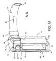
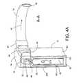
- FIG. 1 and FIG. 1Aare sectional view of a device for intermittent compression of a limb, according to one preferred embodiment of the present invention
- FIG. 2is a sectional view of a device for intermittent compression of a limb, according to a second preferred embodiment of the present invention
- FIGS. 2A , 2 Bshow additional examples of pressure gradient profiles of a device for intermittent compression of a limb
- FIGS. 3 , 3 A and 3 Bare different view aspects of a device for intermittent compression of a limb, according to a third preferred embodiment of the present invention.
- FIGS. 4 and 4Aare views of a device for intermittent compression of a limb, according to a fourth preferred embodiment of the present invention.
- FIGS. 5 and 5Aare views of a device for intermittent compression of a limb, according to a fifth preferred embodiment of the present invention.
- the present inventionprovides a device for providing intermittent compression to a limb, the device comprising, an at least one energy reservoir and an at least one compressing means for compressing the limb, wherein the energy stored in the at least one energy reservoir is pre-stored in the energy reservoir and is directly transformed to provide intermittently compression on the limb.
- the energy reservoirprovides a single energy transformation from energy stored in the reservoir to energy used to compress intermittently the limb.
- the energy stored in the reservoiralso provides the energy for a mechanism controlling the intermittent operation of the device and the release of excess energy from the device.
- the inventionprovides a device for intermittently compressing a limb or any other body part.
- the devicecomprises a strap or a plurality of straps that encircle a limb.
- the deviceactuates intermittently compressing forces on a limb.
- the magnitude of the compressing force applied to during intermittently compressing by the devicevaries according to the parameters referring to the amount of energy stored within the energy reservoir, the time interval designated for applying the compressing forces on the limb, the compressing means used, the efficiency of transferring the energy from the energy reservoir to the compressing means, as well as other parameters.
- the energy stored in the energy reservoirmay be of any form.
- the stored energymay be in the form of a compressed gas or a potential mechanical energy stored in a spring.
- One advantage of the present inventionis that there is no need for an energy source to add or fill the energy reservoir from which energy is transferred to intermittently compressing the limb.
- the devicecan therefore be portable, small and disposable. It can be used until such time where the energy reservoir has been depleted.
- the energy reservoirallows for multiple operation cycles with no need for a separate power source element.
- the energy reservoiritself may be a chargeable reservoir so as to allow re-charging the reservoir after depletion thereby allowing for further sessions of operation.
- Another advantage of the present inventionis that a single energy reservoir can be used both for transforming the energy stored therein both for providing intermittent compression and controlling of the device's intermittent compression operation and cycle.
- the preferred embodiment shownis an energy reservoir storing a fluid such as compressed air and the compressing means is an inflatable strap. It will be appreciated that the present invention will likely apply to any other device or mechanism that can store energy and allow-release thereof to enable by a single transformation of said energy to provide intermittent compression to a limb.
- the stored energymay be in the form of a compressed fluid, a charged spring or energy stored in a battery transformed into electromechanical energy of an electromechanical actuator.
- FIG. 1is top view of a device 10 for intermittent compression of a limb, according to one preferred embodiment of the present invention.
- FIG. 1Ais a cross sectional view of device 10 viewed along line A-A shown in FIG. 1 .
- Device 10comprises a housing 12 and an inflatable sleeve 14 .
- Housing 12is shown in FIG. 1 without base 52 and wall 58 ′.
- Housing 12is preferably positioned juxtaposed to the sleeve 14 which encircles the limb providing a circumference 46 to be compressed on the limb of the user of the device.
- the perimeter of circumference 46can correlate for example to a calf or an arm of a person, although it may be fitted to any limb, preferably in the extremities.
- Device 10can be actuated by a lever mechanism valve 16 enabling the beginning of the release of the energy stored in the energy reservoir 28 within housing 12 to the compressing element.
- the actuationcan be mechanical, electrical, electromagnetic or the like.
- gas or other pressure sourcepreferably generated by a fluid is be released from the reservoir 28 based on the size of the outlet pipe from said reservoir.
- Reservoir 28 and lever mechanism valve 16are placed within housing 12 .
- reservoir 28can comprise a canister shaped chamber with entry opening 40 , said bottle can resemble a small can of compressed air and preferably fabricated from light metal material and double shield walls 62 , 62 ′.
- the canistermay be placed separately on another body part.
- the reservoir 28is disposable and can be replaceable when the fluid there within is depleted. Accordingly, reservoir 28 can be extracted from base 52 of housing 12 . Base 52 can be removed for extracting reservoir 28 and inserting a new reservoir. Base 52 can be removed by sliding on sliding tracks (not shown) attached to walls 58 , 58 ′ of housing 12 or other manner. In another embodiment the entire device is disposable and is for a single use or limited number of uses. The size of the reservoir 28 as well as its housing is determined based on its content and its use, such that if the device is to be operated on public vehicles local rules will dictate aspects of its constructions, such as the material it is manufactured from, the strength of its walls and the like.
- the fluid within reservoir 28is compressed air.
- gassescan be used.
- the preferred fluid to be used in association with the devicewill be a compressible and expandable gas, with high flow characteristics once the kinetic energy stored there within is allowed to be released.
- gaswill maintain low and as close to room temperatures as possible when compressed and expanded without significant kinetic energy loss or change of state.
- gassescan include Nitrogen, Helium, and Carbon Dioxide and the like. If Carbon Dioxide is used within reservoir 28 it is preferably provided with an initial internal pressure of about 15 Atmospheres.
- the initial pressure of reservoir 28can be between about 4 to about 25 Atm., thus allowing sufficient pressure to operate the device for a predetermined length of time.
- the deviceis also constructed such that the rate of diffusion of the gasses used there in is maintained by slow release of the gas from reservoir 28 and the maintaining of the concentration gradient within the device.
- sleeve 14is hollow and provides gas exited from reservoir 28 to be transported there through, so as to enable the compression of the limb within circumference 46 .
- the devicecan include instead or additionally to said sleeve, a strap pulled in and out of housing 12 , or a pair of flaps moved towards and out of the compressed limb, or a plate or an inflatable member also applied towards and out of compressed limb, or the like for providing compression to the limb.
- the sleeve 14 as well as the other compressing elements discussed hereinwill enable the compressing of the limb within circumference 46 at predetermined intervals for certain period of time to be either predetermined or set by an operator or user of the device.
- Sleeve 14is fabricated from substantially non-stretchable nylon or like material and can optionally be put within a sleeve fabricated from synthetic, natural or combination thereof cloth to be applied to the limb itself.
- Sleeve 14comprises two ends 32 and 64 .
- End 64is fixed to entry opening 40 of reservoir 28
- end 32comprises exit opening 50 and can be attached to housing 12 by a user through the use of a strip of hooks 20 appended to end 32 and appended to corresponding loops 18 placed on housing 12 and provides for the fastening of end 32 to housing 12 with attachable materials such as Velcro.
- End 64is attached to housing 12 hooks 48 , 49 .
- Persons skilled in the artwill appreciate that other methods of closure and opening of the sleeve 14 can be applied in connection with the present invention.
- Opening 56 of sleeve 14is juxtaposed to exit opening 50 , thus providing a gas outlet for the gas circulating within sleeve 14 .
- compressed gas held within reservoir 28exits reservoir 28 through entry opening 40 to end 64 of sleeve 14 .
- the gas compression entering sleeve 14is changed from high compression to a lower compression thus achieving greater volume in a relatively short period of time and allowing the quick filling of the volume of space within said sleeve, thus, narrowing the circumference 46 and a quick build up of the pressure gradient on the limb in said circumference.
- the release of the gas into sleeve 14can be moderated by a valve (not shown) such that slower gas filling is achieved and a slower build up of the pressure gradient as against the limb is accomplished.
- the result of narrowing the circumference 46 ofis a compression on said limb and the change in the pressure gradient on said limb.
- the change of gradient pressure, the gradient pressure duration and speed of change of gradient pressure on the limbenable the relief of symptoms associated with ailments associated with peripheral vascular diseases, arterial, venous or combined.
- ailments associated with peripheral vascular diseasescan include venous stasis, vein thrombosis, diabetic foot, arterial sclerosis, varicose veins, arteriovenous fistula and lymphatic disorders like lymphedema and lipedema.
- Other ailments associated with orthopedic conditionssuch as gangrin of the foot, mycosis of the nails, fractures, tendonitis, bursitis and the like.
- device 10provides that the pressure within reservoir 28 and entry opening 40 is substantially larger than the pressure within sleeve 14 and exit opening 50 .
- the variance in pressure within said strap between the areas of entry opening 40 and exit opening 50is exploited in the preferred embodiment to provide an energy releasing mechanism.
- gas entering the sleeve at end 64is at higher pressure than gas present at the same time at end 32 of the sleeve 14 .
- Gas entering the sleevewill deflate the sleeve 14 until such pressure is built so as to provide a sufficient pressure gradient to compress the limb of the user.
- the user of the devicecan manually release gas from reservoir 28 into the sleeve 14 by actuating lever 16 .
- the compressed gas within reservoir 28exits the canister and flows through entry opening 40 via sleeve end 64 into the sleeve 14 .
- the gasOnce sufficient gas entered the sleeve 14 and sufficient pressure was built to apply sufficient compression on the limb, the gas exist the sleeve through exit opening 50 via sleeve end 32 .
- a self controlled pressure mechanismis provided.
- the self controlled pressure mechanismcomprises a sleeve entry valve 16 and a sleeve exit valve 24 .
- Valves 24 , 16are used as an energy regulating mechanism that exploit the energy transfer between reservoir 28 and sleeve 14 .
- the valves 24 , 16regulate the energy conversion rate from energy pre-stored within reservoir 28 to compression force applied by sleeve 14 on said limb.
- Valves 24 , 16provide the energy transfer in predetermined portions. Said portions of the energy transfer are set according to a pre-designated rate of the intermittent compression desired on the limb.
- the intermittent compression rate on the limbcan vary.
- the intermittent compression rate applied by sleeve 14remains substantially constant in a course of predetermined time interval, alternatively, according to another embodiment the intermittent compression rate decreases in a course of predetermined time interval.
- the energy transfer within device 10is the transfer of high pressure gas within reservoir 28 to sleeve 14 .
- the gas transfer direction within sleeve 14is indicated by arrows 42 and 44 . Since gas is present in reservoir 28 at high pressure it can be used to drive a pneumatic actuated on/off valves to allow intermittent opening and closing of the sleeve entry and exit valves 24 , 16 .
- valve 16comprises a ball assembly 60 providing the intermittent opening and closing of gas from reservoir 28 to sleeve 14 .
- the valvescan be associated with a timing device such as a small battery operated watch or timing mechanism to time the opening or closing of the valves. Said timing device controls the intermittent closing and opening of valves 24 , 16 .
- a timing devicesuch as a small battery operated watch or timing mechanism to time the opening or closing of the valves. Said timing device controls the intermittent closing and opening of valves 24 , 16 .
- valve 16while valve 16 is open valve 24 is closed. Consequently to the pressure within reservoir 28 said positions of valves provides flow of a portion of gas from reservoir 28 with high pressure to sleeve 14 .
- valves 24 , 16With a portion of provides a narrowing of the circumference 46 and a quick build up of the pressure gradient on the limb in said circumference.
- the timing devicechanges the position of valves 16 , 24 , thus, closing valve 16 and opening of valve 24 . Consequently, said positions of valves 16 , 24 causes sleeve 14 to deflate. Thus, reducing the pressure on the limb.
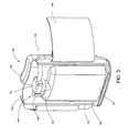
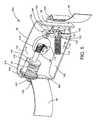
- FIGS. 4 and 4Aare sectional views of a device for intermittent compression of a limb, according to a further preferred embodiment of the present invention.
- Device 200comprises the same elements of device 10 depicted in view of FIGS. 1 and 1A as well as a pressure measuring device 202 .
- Pressure measuring device 202comprises a pressuring measuring indicator unit 212 and pressure measuring sensor 210 .
- Pressuring measuring indicator unit 212is positioned on wall 62 of reservoir 28 and due to a opening on wall 58 ′ of housing 12 (not shown) pressuring measuring indicator 212 can be viewed by looking at wall 58 ′. Thus, providing that indicator 212 can be viewed by a user of device 200 or another person.
- Pressuring measuring indicator unit 212comprises a measuring device housing 208 , a display unit 204 , and a needle 206 .
- Measuring device housing 208is projecting from wall 62 and is adjacent to correlating opening within wall 58 ′ (not shown).
- Needle 206is connected to pressure measuring sensor 210 and indicates the pressure within reservoir 28 by pointing to pressure values on display unit 204 .
- Display unit 204is an analog displaying unit presenting numbers representing different values of pressure units that can indicate various pressure values possible within reservoir 28 .
- a low pressure value interval wherein the device does not provide the required intermittent pressure on limbcan be painted in red or indicate “CHANGE RESERVOIR” (not shown).
- a display unitmay be a digital display unit showing pressure values correlating to the pressure within reservoir 28 .
- a pressure measuring sensorcan be connected to an alarm or LED light, thus, by reaching a predefined pressure threshold an alarm is initiated or a light is lit, respectively, thus notifying a user that the reservoir must be changed or recharged.
- a pressure measuring sensorcan be replaced with other measuring sensors such as a temperature sensor, a humidity sensor, a combination thereof, and the like.
- a display unit connected to a measuring sensormay be a time measuring display unit (e.g.
- a clockindicating a time interval from the commencement of an intermittent compression until a certain predefined threshold wherein the intermittent compression is ineffective or ceased.
- the time measuring display unitis connected to a measuring sensor.
- the time measuring display unitupon receiving mechanical force, magnetic force, electrical signal and the like from a measuring sensor the time measuring display unit will measure the time and display it on a display unit that can be viewed by a user.
- the measuring of the time measuring display unitis ceased according to predefined threshold, e.g. if the pressure within an energy reservoir drops below a predefined value.
- a pressuring measuring indicator unitcan be positioned on the top cover 54 of housing 12 , on other parts of housing 12 , or at a remote position from pressure measuring sensor.
- FIG. 2is cross section top view of a second embodiment in accordance to the present invention. The same principles applied to the device depicted in FIG. 1 are applied to the device of FIG. 2 .
- Device 80comprises a housing 82 and strap 84 .
- Device 80provides intermittent compression on a limb within circumference 86 (not shown).
- Housing 82is positioned juxtaposed to said limb and strap 84 which encircles the limb of a person (not shown) providing substantially an enclosed area or loop.
- Strap 84can be fabricated from a synthetic cloth, natural cloth or a combination thereof substantially not stretchable and not irritating to a skin of a person.
- Strap 84comprises strap ends 120 , 122 .
- Strap end 122is connected to elongated connector plate 96 enabling the strap to be pulled and released in and out of the housing 82 (not indicated in drawing) by way of a connected pull rod 126 so as to apply intermittent compression to the limb, while strap end 120 is attached to the housing 82 through an attaching means such as the hooks and loops disclosed in association with FIG.
- Pull rod 126is pivotally connected by pivot 142 to connecting plates 148 , 149 .
- Connecting platesare pivotally connected to rounded wheel 132 and to stems 133 , 131 (not shown).
- Pivot 140connects plates 148 , 149 to stems 131 , 133 .
- Stems 131 , 133are fixed to wall 129 of housing 82 .
- Housing 82comprises energy reservoir unit and energy releasing mechanism unit.
- energy reservoir unit 110comprises a charged coil 92 connected to wall 114 of housing 82 at one end and to a plunger 94 at the other end.
- Arrow 144indicates the direction of movement of energy reservoir unit 110 .
- the device 80is disposable, in an alternative embodiment of the present invention, the energy reservoir unit 110 is replaceable when the energy in coil 92 is depleted.
- Coil 92converts the stored energy there within to kinetic energy pushing plunger 94 .
- Plunger 94is pivotally attached to a spirally grooved worm shaft 98 .
- Worm shaft 98is coupled to vector changing cogwheel 113 that transfers movement energy to cogwheel 116 which turns around its axis and converts the energy released by coil 92 to a circular motion.
- the circular motion direction of cogwheel 116is indicated by arrow 134 .
- Cogwheel 113is squarely connected perpendicular to its surface by an axis to wheel 116 such that each turn of cogwheel 113 will cause a full turn of cogwheel 116 .
- 116a clutch element can be inserted between said cogwheels to allow the change of speed of cogwheel 116 and the intermittent intervals between one compression and the next. In the embodiment shown in FIG.
- cogwheel 116is substantially round having semi circular rounded shaped teeth 118 suitable for allowing pull rod 126 having a pivotally jointed rounded wheel 132 at its distal end to travel on the horizontal plane indicated by arrow 124 in a crankshaft manner thus actuating the plate 96 and the strap 84 .
- Pull rod 126is connected via axis of jointed rounded wheel 132 to cogwheel 113 by way of a spring 115 allowing pull rod 126 to move horizontally in the direction of arrow 124 maintaining a return force to be applied to pull rod 126 by way of spring 115 .
- the size and shape of wheels 113 , 116 and teeth 118determine the pressure gradient profile to be applied to the limb during the intermittent compression cycle provided by device 80 .
- rounded shaped teeth 118provide a linear pressure gradient to be applied to the limb.
- the use of teeth 118also enables a relative quick pulling and release of strap 84 by means of release of energy stored in spring 92 and transformation of the released energy into circular motion via worm central shaft 98 .
- Cogwheels 113 , 116preferably turn in the direction indicated by arrow 134 providing angular movement consequently applying a movement of pull rod 126 and in turn the movement of strap 84 in the bi-direction of arrow 124 .
- Pulling of strap 84 in the direction of the device 80narrows the circumference of the loop created by said strap 84 and consequently applies pressure on said limb.
- Two additional examples of pressure gradient profilesare briefly presented in FIGS.
- FIG. 2A2 B showing a central worm shaft 98 , and cogwheels 113 , 116 .
- the shape of the cogwheel 116is uneven thus providing a different pressure gradient profile to be used during the intermittent compression cycle on the limb.
- the cogwheel 116 of FIG. 2Aprovides a longer yet larger pulling of the strap 84 by the movement of pull rod 126 along substantially the entire axis 124 based on the shape of cogwheel 116 .
- FIG. 2Ashows a central worm shaft 98 , and cogwheels 113 , 116 .
- FIG. 2Athe shape of the cogwheel 116 is uneven thus providing a different pressure gradient profile to be used during the intermittent compression cycle on the limb.
- the cogwheel 116 of FIG. 2Aprovides a longer yet larger pulling of the strap 84 by the movement of pull rod 126 along substantially the entire axis 124 based on the shape of cogwheel 116 .
- FIG. 1shows a central worm shaft
- 2B cogwheel 116is rounded having quarter circular shapes having an ascending slope 138 and a sharp drop 140 there after enabling short but moderate release of the strap 84 and a swift and immediate pull of the strap when jointed rounded wheel 132 and pull rod 126 are pulled into recess 140 by means of spring 115 .
- spring 115a multitude of pressure gradient profiles can be applied to a user of device 80 depending on the required usage. While the embodiment depicted in FIGS.
- the present inventionfurther contemplates the use of a compressible plate adjusted to the limb of the patient.
- a compressible plateadjusted to the limb of the patient.
- Such platecan be rectangular, round, or limb shape oriented to fit the limb, and be placed on either side of the limb with the aid of straps (to allow attaching the device and the plate to the limb, but not necessarily encircling the limb) so as to apply intermittent compression.
- the compression elementis the strap or sleeve encircling the limb
- the compression elementmay be a plate may be it will be realized that inflated, in other embodiments of the invention the compression element may be a compressing plate
- FIGS. 5 and 5Aare sectional view of a chargeable device for intermittent compression of a limb.
- FIGS. 5 and 5Aillustrate a chargeable device 300 that comprises substantially the same elements comprised in FIG. 2 wherein cogwheel 116 is replaced with an uneven circular cogwheel depicted in view of FIG. 2A .
- Chargeable device 300further comprises a charging cogwheel 302 .
- Charging cogwheel 302is projects from housing 82 through openings 306 , 307 (not shown) within walls 314 , 315 , respectively.
- Cogwheel 302is pivotally connected to wall 114 by a pivot 303 (not shown) attached to wall 114 .
- Cogwheel 302comprises bases 304 , 316 and teeth 308 .
- Base 316comprises a number of depressions 324 spaced between, that are adjacent to the circumference of base 316 .
- Coil 92connected to base 304 juxtaposed to wall 114 of housing 82 at one end, and to a plunger 94 at the other end.
- Charging cogwheel 302enables recharging of coil 92 with potential energy.
- cogwheel 302provides reuse of device 300 for intermittent compression also after all previously stored energy within coil 92 was depleted.
- device 300is provided with a charged coil 92 ready to use for intermittent compression. Accordingly, device 300 can be placed adjacent to a limb for initiating intermittent compression on said limb.
- Cogwheel 302enables recharging coil 92 thus enabling to restart intermittent compression on limb also after energy within coil 92 is depleted.
- Charging coil 92is performed by turning cogwheel 302 in the opposite direction of arrow 144 . Due to the fact that end of coil 92 is attached to base 308 , coil 92 is charged when cogwheel 302 is turned. According to the preferred embodiment charging cogwheel 302 can charge coil 92 while straps 120 , 122 are loose, or alternatively, not stretched around a limb.
- the charging energy of energy reservoiris performed while the straps are stretched on a limb.
- Other embodimentscan comprise other charging elements for charging a coil or other energy reservoir such as lever charging a coil and the like.
- the chargercan be a combination of mechanical using electrical energy such as a battery moving a cogwheel or a lever and the like. Turning charging cogwheel 308 in the opposite direction of arrow 144 is done is performed manually by a user (not shown) as long as allowed by the elastic performance of coil 92 .
- Chargeable device 300comprises further a knob 312 that is place within opening 320 positioning in housing 82 adjacent to opening 306 and base 316 .
- Knob 312comprises an elongated element 318 and rounded push button top 322 . Top 322 is wider than the width of element 318 . Knob 312 is used to hold cogwheel 302 in its position or to provide its circular motion. Knob 312 can stop a motion of cogwheel 302 when pushed, thus element 318 placed within depression 324 does not allow motion of cogwheel 302 . Due to the fact that coil 92 is connected to base 304 a charged coil 92 will not proceed transferring its energy to intermittent compression as depicted above when knob 312 is prevention motion of cogwheel 302 . Similarly, the initiation of intermittent compression can be initiated when knob 312 is pulled out from depression 324 .
- a deviceaccording to the embodiments depicted in FIGS. 2 , 2 A, 2 B, 5 and 5 A can be provided with a measuring device comprising a measuring sensor and a measuring display unit.
- the sensorcan be connected to a plunger such as plunger 94 in FIG. 2 .
- an advancement of said coilcan indicate by a lever connected to knob (not shown) placed on housing that can be viewed on the exterior of housing 82 .
- the compressing elementis the strap or sleeve encircling the limb
- the compressing elementmay be a movable compressing plate fastened to the limb, such as described in International Publication WO02069879, the full content of which is incorporated herein by reference.
- FIGS. 3 , 3 A and 3 Bthat provide a side view, and bottom view of device 150 comprises housing 152 and strap 154 .
- FIGS. 3 and 3Apresent housing 152 cut open without wall 184 (shown in FIGS. 3B and 3C ).
- Housing 152is placed juxtaposed to limb of a person (not shown) and strap 154 encircles said limb providing a loop (not shown).
- Housing 152comprises an energy reservoir unit 156 having one or more compressed gas chambers 157 , an energy releasing mechanism 178 , and a bladder 158 .
- Device 150provides intermittent compression on a limb by deflating and inflating bladder 158 while straps 154 remain constant in circumference and hold the device 150 to the limb of the user.
- the intermittent contracting of loop 184 (not shown) encircling said limbis reached by intermittently providing gas in and out of bladder 158 .
- the intermittent compression on limbis reached by intermittently providing bladder 158 with compressed gas from reservoir 156 and releasing air from bladder via bladder release opening 160 .
- Energy reservoir unit 156can be similar to energy reservoir 28 depicted in association with FIG. 1 above.
- Compressed gas stored within energy reservoir 157can be released intermittently through the opening and closing of a moveable valve (not shown) operated by a pneumatic actuated valve mechanism provided with a steady stream of compressed gas through narrow pipe 164 .
- the gas delivered to the pneumatic actuated valve mechanism 162actuates intermittent opening and closing of the valve releasing air into bladder 158 and opening and closing of the valve releasing the gas within bladder 158 into bladder release opening 160 .
- FIGS. 3B and 3Care the bottom view of device 150 .
- Housing 152comprises further opening 182 that provides inserting and extracting of energy reservoir 157 . Accordingly, if the energy within energy reservoir 157 drops below a pre-designated level reservoir 157 can be replaced with another reservoir with the same dimension.
- the pressure of gas within energy reservoir 157is insufficient to inflate bladder 158 and provide required intermittent compression top 180 is removed from opening 182 and reservoir 157 is replaced with another reservoir.
- removal of reservoircan be made from top, side, or bottom part of housing 152 .
- the indication of insufficient intermittent compressioncan be indicated by a pressure measuring device as depicted above in view of FIGS. 4 and 4A , by the sensing of user of device 150 , or other means.
- Reservoir 157can be disposed or reused by inserting pressured gas.
- different energy reservoirscan be used in association with the embodiments depicted above or like embodiments.
- Such energy reservoirscan include in addition to the depicted reservoirs chambers comprising gas generated there within through chemical processes, electromagnetic, electrical, magnetic, mechanical temperature related energy and the like.
- more than one energy reservoircan be used in association with a single device.
- the energy reservoircan be disposable and be replaced when depleted by pulling the energy reservoir cartridge from the intermittent compression device and inserting a new cartridge comprising an energy reservoir into the intermittent compression device.
- the deviceitself can be disposable once the energy reservoir it is manufactured with has been depleted.
- a small timing mechanismcan control the timing of the release of the energy thus better controlling the intermittent intervals and the energy gradient profiles set for the device by a user or the manufacturer.
Landscapes
- Health & Medical Sciences (AREA)
- Epidemiology (AREA)
- Pain & Pain Management (AREA)
- Physical Education & Sports Medicine (AREA)
- Rehabilitation Therapy (AREA)
- Life Sciences & Earth Sciences (AREA)
- Animal Behavior & Ethology (AREA)
- General Health & Medical Sciences (AREA)
- Public Health (AREA)
- Veterinary Medicine (AREA)
- Percussion Or Vibration Massage (AREA)
Abstract
Description
Claims (24)
Applications Claiming Priority (3)
| Application Number | Priority Date | Filing Date | Title |
|---|---|---|---|
| IL16436004AIL164360A0 (en) | 2004-09-29 | 2004-09-29 | A device for providing intermittent compression toa limb |
| IL164360 | 2004-09-29 | ||
| PCT/IL2005/001057WO2006035449A1 (en) | 2004-09-29 | 2005-09-29 | A device for providing intermittent compression to a limb |
Publications (2)
| Publication Number | Publication Date |
|---|---|
| US20080097268A1 US20080097268A1 (en) | 2008-04-24 |
| US8105252B2true US8105252B2 (en) | 2012-01-31 |
Family
ID=36118622
Family Applications (1)
| Application Number | Title | Priority Date | Filing Date |
|---|---|---|---|
| US11/575,722Expired - Fee RelatedUS8105252B2 (en) | 2004-09-29 | 2005-09-29 | Device for providing intermittent compression to a limb |
Country Status (3)
| Country | Link |
|---|---|
| US (1) | US8105252B2 (en) |
| IL (1) | IL164360A0 (en) |
| WO (1) | WO2006035449A1 (en) |
Cited By (17)
| Publication number | Priority date | Publication date | Assignee | Title |
|---|---|---|---|---|
| US20050107725A1 (en)* | 2003-03-27 | 2005-05-19 | Wild David G. | Compression device for the limb |
| US20070038167A1 (en)* | 2005-06-08 | 2007-02-15 | Bristol-Myers Squibb Company | Compression device for the foot |
| US20070249976A1 (en)* | 2006-01-24 | 2007-10-25 | Bristol-Myers Squibb Company | Proximity detection apparatus |
| US20080066272A1 (en)* | 2006-09-12 | 2008-03-20 | Hammerslag Gary R | Closure System For Braces, Protective Wear And Similar Articles |
| US20100056966A1 (en)* | 2006-01-13 | 2010-03-04 | Landy Toth | Device, system and method for compression treatment of a body part |
| US20100130889A1 (en)* | 2007-01-24 | 2010-05-27 | Convatec Technologies Inc. | Elastomeric particle having an electrically conducting surface, a pressure sensor comprising said particles, a method for producing said sensor and a sensor system comprising said sensors |
| US20110066091A1 (en)* | 2004-10-11 | 2011-03-17 | Convatec Technologies Inc. | Electro active compression bandage |
| US8424168B2 (en) | 2008-01-18 | 2013-04-23 | Boa Technology, Inc. | Closure system |
| US8468657B2 (en) | 2008-11-21 | 2013-06-25 | Boa Technology, Inc. | Reel based lacing system |
| US9149089B2 (en) | 2010-07-01 | 2015-10-06 | Boa Technology, Inc. | Lace guide |
| US9179729B2 (en) | 2012-03-13 | 2015-11-10 | Boa Technology, Inc. | Tightening systems |
| US9393026B2 (en) | 2012-04-25 | 2016-07-19 | W. L. Gore & Associates, Inc. | Vessel compression devices and methods |
| US10499709B2 (en) | 2016-08-02 | 2019-12-10 | Boa Technology Inc. | Tension member guides of a lacing system |
| US11297903B2 (en) | 2011-10-13 | 2022-04-12 | Boa Technology, Inc. | Reel-based lacing system |
| US11471116B2 (en) | 2006-01-24 | 2022-10-18 | Swelling Solutions, Inc. | Control unit assembly |
| US12144401B2 (en) | 2013-06-05 | 2024-11-19 | Boa Technology, Inc. | Integrated closure device components and methods |
| US12256803B2 (en) | 2019-02-01 | 2025-03-25 | Boa Technology Inc. | Reel based closure devices for tightening a ski boot |
Families Citing this family (16)
| Publication number | Priority date | Publication date | Assignee | Title |
|---|---|---|---|---|
| IL141824A (en) | 2001-03-05 | 2008-11-03 | Flowmedic Ltd | Portable device for the enhancement of the circulation and for the prevention of stasis related deep vein thrombosis (dvt) |
| IL160185A0 (en)* | 2004-02-02 | 2004-07-25 | Flowmedic Israel Ltd | A portable device for the enhancement of circulation of blood and lymph flow in a limb |
| IL164286A0 (en) | 2004-09-26 | 2005-12-18 | Benny Rousso | A portable device for the enhancement of blood circulation |
| US8079969B2 (en)* | 2004-06-09 | 2011-12-20 | Benny Rousso | Portable self-contained device for enhancing circulation |
| IL164360A0 (en) | 2004-09-29 | 2005-12-18 | Benny Rousso | A device for providing intermittent compression toa limb |
| US8235921B2 (en) | 2005-05-01 | 2012-08-07 | Flow Medic Limited | Computerized portable device for the enhancement of circulation |
| US7981066B2 (en)* | 2006-05-24 | 2011-07-19 | Michael Paul Lewis | External pulsation treatment apparatus |
| EP2162109A4 (en)* | 2007-06-20 | 2012-10-03 | Remo Moomiaie-Qajar | Portable compression device |
| JP2012146921A (en) | 2011-01-14 | 2012-08-02 | Denso Corp | Silicon carbide semiconductor device |
| HK1202033A1 (en)* | 2011-12-02 | 2015-09-18 | Avex, Llc | Spring-driven foot compression system |
| US10369075B2 (en) | 2015-03-03 | 2019-08-06 | Avex, Llc | Insole foot compression system and methods |
| US10076462B2 (en) | 2016-04-27 | 2018-09-18 | Radial Medical, Inc. | Adaptive compression therapy systems and methods |
| CN115670435B (en)* | 2018-07-25 | 2025-07-04 | 何哲彦 | Limb circumference detection device, limb compliance measurement device and lymphedema treatment device composed of the device |
| EP3598941B1 (en)* | 2018-07-25 | 2021-09-15 | Yer-Yien Hoe | An apparatus for measurement of a limb circumference, a device for measurement of a limb compliance comprising the same and a device used in the treatment of lymphedema comprising the same |
| CN109998886A (en)* | 2019-04-30 | 2019-07-12 | 北京国润健康医学投资有限公司 | Portable external counterpulsation convalescence device and method of rehabilitation based on electrocardio control |
| CN116785117A (en)* | 2023-05-08 | 2023-09-22 | 汉菱(深圳)医疗科技有限公司 | Arteriovenous fistula training control method, arteriovenous fistula training control device and storage medium |
Citations (63)
| Publication number | Priority date | Publication date | Assignee | Title |
|---|---|---|---|---|
| US718766A (en) | 1902-10-14 | 1903-01-20 | Thomas D Ingram | Massage-machine. |
| US1366537A (en)* | 1919-10-03 | 1921-01-25 | Thomas J Masse | Indicator for spring-motors |
| US1384272A (en)* | 1917-09-10 | 1921-07-12 | Bernard S Nickerson | Spring-motor-controlling mechanism |
| US1472936A (en)* | 1917-02-20 | 1923-11-06 | Henry L Pitman | Spring motor |
| CH187824A (en) | 1936-01-24 | 1936-11-30 | Mueller Richard | Massage belt to be set in vibration by motor drive. |
| US2118699A (en) | 1936-02-18 | 1938-05-24 | Bally Mfg Company | Vibrator and holder therefor |
| US3804084A (en) | 1973-03-05 | 1974-04-16 | I Lehman | Knee support |
| US3853121A (en) | 1973-03-07 | 1974-12-10 | B Mizrachy | Methods for reducing the risk of incurring venous thrombosis |
| US4004579A (en) | 1975-10-08 | 1977-01-25 | Dedo Richard G | Respiratory assist device |
| US4243039A (en) | 1979-06-13 | 1981-01-06 | Yacov Aginsky | Emergency tourniquet |
| US4333181A (en) | 1980-05-16 | 1982-06-08 | John Corriero | Protective structures for joints |
| US4396010A (en) | 1980-06-30 | 1983-08-02 | The Kendall Company | Sequential compression device |
| US4542649A (en)* | 1983-07-19 | 1985-09-24 | Charbonneau And Godfrey Associates | Motor operated valve analysis and testing system |
| US4732140A (en) | 1986-08-18 | 1988-03-22 | Stoffregen Robert T | Vibratory massager retained against body with belt having elastic strap |
| US4770164A (en) | 1980-10-16 | 1988-09-13 | Lach Ralph D | Resuscitation method and apparatus |
| US4928674A (en) | 1988-11-21 | 1990-05-29 | The Johns Hopkins University | Cardiopulmonary resuscitation and assisted circulation system |
| US4982732A (en) | 1990-02-06 | 1991-01-08 | Orthopedic Technology, Inc. | Orthopedic rehabilitation knee brace |
| US5009222A (en) | 1989-07-24 | 1991-04-23 | Her Ming Long | Diving case massager |
| US5277697A (en) | 1990-08-17 | 1994-01-11 | Hanger Orthopedic Group, Inc. | Patella-femoral brace |
| US5334131A (en) | 1993-08-20 | 1994-08-02 | Omandam Ismael C | Strap-on massager with vibratory unbalanced weight |
| US5399153A (en) | 1991-10-15 | 1995-03-21 | Tru-Fit Marketing Corporation | Adjustable knee support |
| US5407418A (en) | 1993-10-14 | 1995-04-18 | Szpur; Roman | Pulsating compressor apparatus for enhancing blood flow |
| US5454831A (en) | 1991-09-30 | 1995-10-03 | Abatis Medical Technologies Ltd. | Occlusive cuff system |
| US5472413A (en) | 1994-10-07 | 1995-12-05 | Pro Orthopedic Devices, Inc. | Universal fit knee and elbow braces with spiders |
| US5513658A (en) | 1994-03-30 | 1996-05-07 | Morito Kabushiki Gaisha | Knee supporter |
| US5575761A (en) | 1994-07-27 | 1996-11-19 | Hajianpour; Mohammed-Ali | Massage device applying variable-frequency vibration in a variable pulse sequence |
| WO1997004820A2 (en) | 1995-07-27 | 1997-02-13 | Yehuda Zicherman | Vibrator appliance particularly useful for dialysis |
| US5738637A (en) | 1995-12-15 | 1998-04-14 | Deca-Medics, Inc. | Chest compression apparatus for cardiac arrest |
| US5769801A (en) | 1993-06-11 | 1998-06-23 | Ndm Acquisition Corp. | Medical pumping apparatus |
| US5865776A (en) | 1997-04-09 | 1999-02-02 | Ortho-Care, Inc. | Knee brace having differential flexibility posterior and anterior panels |
| US5873848A (en) | 1996-06-14 | 1999-02-23 | Depuy, Inc. | Orthopedic brace |
| DE19815487A1 (en) | 1998-04-07 | 1999-10-14 | Fraunhofer Ges Forschung | Method for operating a massage device and massage device |
| US6010470A (en) | 1995-07-10 | 2000-01-04 | The United States Of America As Represented By The Secretary Of The Air Force | Automated retrograde inflation cardiopulmonary resuscitation trousers |
| WO2000023034A1 (en) | 1998-10-16 | 2000-04-27 | Cantrell Elroy T | Chest mounted cardio pulmonary resuscitation device and system |
| WO2000027334A2 (en) | 1998-11-09 | 2000-05-18 | Johns Hopkins University | Automated chest compression apparatus |
| US6135116A (en) | 1997-07-28 | 2000-10-24 | Kci Licensing, Inc. | Therapeutic method for treating ulcers |
| WO2001032124A1 (en) | 1999-11-04 | 2001-05-10 | A.D.M. Advanced Dialysis Methods | Vibrator for constipation |
| US6231532B1 (en) | 1998-10-05 | 2001-05-15 | Tyco International (Us) Inc. | Method to augment blood circulation in a limb |
| US6290662B1 (en) | 1999-05-28 | 2001-09-18 | John K. Morris | Portable, self-contained apparatus for deep vein thrombosis (DVT) prophylaxis |
| WO2001091364A2 (en) | 2000-05-19 | 2001-11-29 | Theracardia, Inc. | Methods, apparatus and systems for hemodynamic augmentation of cardiac massage |
| WO2002069879A1 (en) | 2001-03-05 | 2002-09-12 | David Weintraub | A portable device for the enhancement of circulation and for the prevention of stasis related dvt |
| US6478757B1 (en) | 1997-08-31 | 2002-11-12 | Medical Compression Systems (D. B. N.) | Device for pressurizing limbs |
| US20020169399A1 (en) | 2001-05-10 | 2002-11-14 | Rastegar Jahangir S. | External counterpulsation cardiac assist device |
| US20020177793A1 (en) | 2001-05-25 | 2002-11-28 | Sherman Darren R. | CPR assist device with pressure bladder feedback |
| US6494852B1 (en) | 1998-03-11 | 2002-12-17 | Medical Compression Systems (Dbn) Ltd. | Portable ambulant pneumatic compression system |
| US6551280B1 (en) | 2000-06-30 | 2003-04-22 | Embro Corporation | Therapeutic device and system |
| US6780163B1 (en) | 2001-02-27 | 2004-08-24 | John H. Krusenklaus | Strap system for treating shin pain |
| US20050043657A1 (en) | 2003-08-21 | 2005-02-24 | Scimed Life Systems, Inc. | External counterpulsation device using electroactive polymer actuators |
| WO2005051250A1 (en) | 2003-11-30 | 2005-06-09 | Flowmedic Limited | A method and apparatus for enhancement of circulation within cast incased body part |
| WO2005072674A1 (en) | 2002-03-03 | 2005-08-11 | Flowmedic Limited | A portable device for the enhancement of circulation of blood and lymph flow in a limb |
| WO2005074376A2 (en) | 2003-09-03 | 2005-08-18 | Benny Rousso | A method and system for external counterpulsation |
| US20050267387A1 (en) | 2004-05-27 | 2005-12-01 | Mary Baldauf | Apparatus for mechanically ventilating a patient |
| WO2005122269A2 (en) | 2004-06-09 | 2005-12-22 | Flowmedic Limited | Functional device with a detachable component |
| WO2005120500A2 (en) | 2003-09-03 | 2005-12-22 | Flowmedic Limited | Sleeves for accommodating a circulation enhancement device |
| WO2005120424A2 (en) | 2004-06-09 | 2005-12-22 | Flowmedic Limited | A portable self-contained device for enhancing circulation |
| US7004919B2 (en) | 2003-07-21 | 2006-02-28 | Medical Specialties, Inc. | Patella stabilizing knee brace |
| US20060047232A1 (en) | 2004-09-01 | 2006-03-02 | Robert Bourne | Back training device |
| WO2006033115A2 (en) | 2004-09-26 | 2006-03-30 | Benny Rousso | A portable device for the enhancement of circulation |
| WO2006033114A2 (en) | 2004-09-26 | 2006-03-30 | Flowmedic Limited | A portable device for the enhancement of circulation |
| WO2006035449A1 (en) | 2004-09-29 | 2006-04-06 | Flowmedic Limited | A device for providing intermittent compression to a limb |
| US7025738B2 (en) | 1999-02-24 | 2006-04-11 | Lohmann Rauscher | Compression support sleeve |
| US20060122546A1 (en) | 2004-09-26 | 2006-06-08 | Benny Rousso | Portable device for the enhancement of circulation |
| WO2006117771A1 (en) | 2005-05-01 | 2006-11-09 | Flowmedic Limited | A computerized portable device for the enhancement of circulation |
- 2004
- 2004-09-29ILIL16436004Apatent/IL164360A0/enunknown
- 2005
- 2005-09-29USUS11/575,722patent/US8105252B2/ennot_activeExpired - Fee Related
- 2005-09-29WOPCT/IL2005/001057patent/WO2006035449A1/enactiveApplication Filing
Patent Citations (77)
| Publication number | Priority date | Publication date | Assignee | Title |
|---|---|---|---|---|
| US718766A (en) | 1902-10-14 | 1903-01-20 | Thomas D Ingram | Massage-machine. |
| US1472936A (en)* | 1917-02-20 | 1923-11-06 | Henry L Pitman | Spring motor |
| US1384272A (en)* | 1917-09-10 | 1921-07-12 | Bernard S Nickerson | Spring-motor-controlling mechanism |
| US1366537A (en)* | 1919-10-03 | 1921-01-25 | Thomas J Masse | Indicator for spring-motors |
| CH187824A (en) | 1936-01-24 | 1936-11-30 | Mueller Richard | Massage belt to be set in vibration by motor drive. |
| US2118699A (en) | 1936-02-18 | 1938-05-24 | Bally Mfg Company | Vibrator and holder therefor |
| US3804084A (en) | 1973-03-05 | 1974-04-16 | I Lehman | Knee support |
| US3853121A (en) | 1973-03-07 | 1974-12-10 | B Mizrachy | Methods for reducing the risk of incurring venous thrombosis |
| US4004579A (en) | 1975-10-08 | 1977-01-25 | Dedo Richard G | Respiratory assist device |
| US4243039A (en) | 1979-06-13 | 1981-01-06 | Yacov Aginsky | Emergency tourniquet |
| US4333181A (en) | 1980-05-16 | 1982-06-08 | John Corriero | Protective structures for joints |
| US4396010A (en) | 1980-06-30 | 1983-08-02 | The Kendall Company | Sequential compression device |
| US4770164A (en) | 1980-10-16 | 1988-09-13 | Lach Ralph D | Resuscitation method and apparatus |
| US4542649A (en)* | 1983-07-19 | 1985-09-24 | Charbonneau And Godfrey Associates | Motor operated valve analysis and testing system |
| US4732140A (en) | 1986-08-18 | 1988-03-22 | Stoffregen Robert T | Vibratory massager retained against body with belt having elastic strap |
| US4928674A (en) | 1988-11-21 | 1990-05-29 | The Johns Hopkins University | Cardiopulmonary resuscitation and assisted circulation system |
| US5009222A (en) | 1989-07-24 | 1991-04-23 | Her Ming Long | Diving case massager |
| US4982732A (en) | 1990-02-06 | 1991-01-08 | Orthopedic Technology, Inc. | Orthopedic rehabilitation knee brace |
| US5277697A (en) | 1990-08-17 | 1994-01-11 | Hanger Orthopedic Group, Inc. | Patella-femoral brace |
| US5454831A (en) | 1991-09-30 | 1995-10-03 | Abatis Medical Technologies Ltd. | Occlusive cuff system |
| US5399153A (en) | 1991-10-15 | 1995-03-21 | Tru-Fit Marketing Corporation | Adjustable knee support |
| US5769801A (en) | 1993-06-11 | 1998-06-23 | Ndm Acquisition Corp. | Medical pumping apparatus |
| US5334131A (en) | 1993-08-20 | 1994-08-02 | Omandam Ismael C | Strap-on massager with vibratory unbalanced weight |
| US5407418A (en) | 1993-10-14 | 1995-04-18 | Szpur; Roman | Pulsating compressor apparatus for enhancing blood flow |
| US5513658A (en) | 1994-03-30 | 1996-05-07 | Morito Kabushiki Gaisha | Knee supporter |
| US5575761A (en) | 1994-07-27 | 1996-11-19 | Hajianpour; Mohammed-Ali | Massage device applying variable-frequency vibration in a variable pulse sequence |
| US5472413A (en) | 1994-10-07 | 1995-12-05 | Pro Orthopedic Devices, Inc. | Universal fit knee and elbow braces with spiders |
| US6010470A (en) | 1995-07-10 | 2000-01-04 | The United States Of America As Represented By The Secretary Of The Air Force | Automated retrograde inflation cardiopulmonary resuscitation trousers |
| WO1997004820A2 (en) | 1995-07-27 | 1997-02-13 | Yehuda Zicherman | Vibrator appliance particularly useful for dialysis |
| US5738637A (en) | 1995-12-15 | 1998-04-14 | Deca-Medics, Inc. | Chest compression apparatus for cardiac arrest |
| US5873848A (en) | 1996-06-14 | 1999-02-23 | Depuy, Inc. | Orthopedic brace |
| US5865776A (en) | 1997-04-09 | 1999-02-02 | Ortho-Care, Inc. | Knee brace having differential flexibility posterior and anterior panels |
| US6135116A (en) | 1997-07-28 | 2000-10-24 | Kci Licensing, Inc. | Therapeutic method for treating ulcers |
| US6478757B1 (en) | 1997-08-31 | 2002-11-12 | Medical Compression Systems (D. B. N.) | Device for pressurizing limbs |
| US6494852B1 (en) | 1998-03-11 | 2002-12-17 | Medical Compression Systems (Dbn) Ltd. | Portable ambulant pneumatic compression system |
| DE19815487A1 (en) | 1998-04-07 | 1999-10-14 | Fraunhofer Ges Forschung | Method for operating a massage device and massage device |
| US6231532B1 (en) | 1998-10-05 | 2001-05-15 | Tyco International (Us) Inc. | Method to augment blood circulation in a limb |
| US6174295B1 (en) | 1998-10-16 | 2001-01-16 | Elroy T. Cantrell | Chest mounted cardio pulmonary resuscitation device and system |
| WO2000023034A1 (en) | 1998-10-16 | 2000-04-27 | Cantrell Elroy T | Chest mounted cardio pulmonary resuscitation device and system |
| WO2000027334A2 (en) | 1998-11-09 | 2000-05-18 | Johns Hopkins University | Automated chest compression apparatus |
| US20020026131A1 (en) | 1998-11-09 | 2002-02-28 | Halperin Henry R. | Automated chest compression apparatus |
| US7025738B2 (en) | 1999-02-24 | 2006-04-11 | Lohmann Rauscher | Compression support sleeve |
| US6290662B1 (en) | 1999-05-28 | 2001-09-18 | John K. Morris | Portable, self-contained apparatus for deep vein thrombosis (DVT) prophylaxis |
| WO2001032124A1 (en) | 1999-11-04 | 2001-05-10 | A.D.M. Advanced Dialysis Methods | Vibrator for constipation |
| WO2001091364A2 (en) | 2000-05-19 | 2001-11-29 | Theracardia, Inc. | Methods, apparatus and systems for hemodynamic augmentation of cardiac massage |
| US6551280B1 (en) | 2000-06-30 | 2003-04-22 | Embro Corporation | Therapeutic device and system |
| US6780163B1 (en) | 2001-02-27 | 2004-08-24 | John H. Krusenklaus | Strap system for treating shin pain |
| US20040073146A1 (en)* | 2001-03-05 | 2004-04-15 | David Weintraub | Portable device for the enhancement of circulation and for the prevention of stasis related dvt |
| WO2002069879A1 (en) | 2001-03-05 | 2002-09-12 | David Weintraub | A portable device for the enhancement of circulation and for the prevention of stasis related dvt |
| US20020169399A1 (en) | 2001-05-10 | 2002-11-14 | Rastegar Jahangir S. | External counterpulsation cardiac assist device |
| US20020177793A1 (en) | 2001-05-25 | 2002-11-28 | Sherman Darren R. | CPR assist device with pressure bladder feedback |
| US6616620B2 (en) | 2001-05-25 | 2003-09-09 | Revivant Corporation | CPR assist device with pressure bladder feedback |
| WO2005072674A1 (en) | 2002-03-03 | 2005-08-11 | Flowmedic Limited | A portable device for the enhancement of circulation of blood and lymph flow in a limb |
| US20060074362A1 (en) | 2002-03-03 | 2006-04-06 | Benny Rousso | Portable device for the enhancement of circulation of blood and lymph flow in a limb |
| US7004919B2 (en) | 2003-07-21 | 2006-02-28 | Medical Specialties, Inc. | Patella stabilizing knee brace |
| US20050043657A1 (en) | 2003-08-21 | 2005-02-24 | Scimed Life Systems, Inc. | External counterpulsation device using electroactive polymer actuators |
| WO2005074376A2 (en) | 2003-09-03 | 2005-08-18 | Benny Rousso | A method and system for external counterpulsation |
| WO2005120500A2 (en) | 2003-09-03 | 2005-12-22 | Flowmedic Limited | Sleeves for accommodating a circulation enhancement device |
| US20080039752A1 (en) | 2003-09-03 | 2008-02-14 | Benny Rousso | Portable Device For The Enhancement Of Circulation |
| US20070055188A1 (en) | 2003-11-30 | 2007-03-08 | Flowmedic Limited | Supportive structure and circulation enhancing apparatus |
| WO2005051250A1 (en) | 2003-11-30 | 2005-06-09 | Flowmedic Limited | A method and apparatus for enhancement of circulation within cast incased body part |
| US20080269543A1 (en) | 2004-02-02 | 2008-10-30 | Benny Rousso | Functional Device with a Detachable Component |
| US20070173886A1 (en) | 2004-02-04 | 2007-07-26 | Flowmedic Limited | Method and system for external counterpulsation |
| US20050267387A1 (en) | 2004-05-27 | 2005-12-01 | Mary Baldauf | Apparatus for mechanically ventilating a patient |
| US20080255494A1 (en) | 2004-06-06 | 2008-10-16 | Flowmedic Limited | Sleeves for Accommodating a Circulation Enhancement Device |
| WO2005122269A2 (en) | 2004-06-09 | 2005-12-22 | Flowmedic Limited | Functional device with a detachable component |
| US20080146980A1 (en) | 2004-06-09 | 2008-06-19 | Benny Rousso | Portable Self-Contained Device for Enhancing Circulation |
| WO2005120424A2 (en) | 2004-06-09 | 2005-12-22 | Flowmedic Limited | A portable self-contained device for enhancing circulation |
| US20060047232A1 (en) | 2004-09-01 | 2006-03-02 | Robert Bourne | Back training device |
| WO2006033115A2 (en) | 2004-09-26 | 2006-03-30 | Benny Rousso | A portable device for the enhancement of circulation |
| US20080015630A1 (en) | 2004-09-26 | 2008-01-17 | Benny Rousso | Portable Device for the Enhancement of Circulation |
| US20060122546A1 (en) | 2004-09-26 | 2006-06-08 | Benny Rousso | Portable device for the enhancement of circulation |
| WO2006033114A2 (en) | 2004-09-26 | 2006-03-30 | Flowmedic Limited | A portable device for the enhancement of circulation |
| US20080097268A1 (en) | 2004-09-29 | 2008-04-24 | Benny Rousso | Device for Providing Intermittent Compression to a Limb |
| WO2006035449A1 (en) | 2004-09-29 | 2006-04-06 | Flowmedic Limited | A device for providing intermittent compression to a limb |
| WO2006117771A1 (en) | 2005-05-01 | 2006-11-09 | Flowmedic Limited | A computerized portable device for the enhancement of circulation |
| US20090118651A1 (en) | 2005-05-01 | 2009-05-07 | Benny Rousso | Computerized portable device for the enhancement of circulation |
Cited By (40)
| Publication number | Priority date | Publication date | Assignee | Title |
|---|---|---|---|---|
| US9539166B2 (en) | 2003-03-27 | 2017-01-10 | Swelling Solutions, Inc. | Compression device for the limb |
| US9044372B2 (en) | 2003-03-27 | 2015-06-02 | Swelling Solutions, Inc. | Compression device for the limb |
| US20050107725A1 (en)* | 2003-03-27 | 2005-05-19 | Wild David G. | Compression device for the limb |
| US10772790B2 (en) | 2003-03-27 | 2020-09-15 | Tactile Systems Technology Inc. | Compression device for the limb |
| US20110066091A1 (en)* | 2004-10-11 | 2011-03-17 | Convatec Technologies Inc. | Electro active compression bandage |
| US8517963B2 (en) | 2004-10-11 | 2013-08-27 | Swelling Solutions, Inc. | Electro active compression bandage |
| US10071012B2 (en) | 2004-10-11 | 2018-09-11 | Swelling Solutions, Inc. | Electro active compression bandage |
| US11154451B2 (en) | 2005-06-08 | 2021-10-26 | Swelling Solutions, Inc. | Compression device for the foot |
| US20070049852A1 (en)* | 2005-06-08 | 2007-03-01 | Bristol-Myers Squibb Company | A cuff for providing compression to a limb |
| US9463135B2 (en) | 2005-06-08 | 2016-10-11 | Swelling Solutions, Inc. | Compression device for the foot |
| US9278043B2 (en) | 2005-06-08 | 2016-03-08 | Swelling Solutions, Inc. | Cuff for providing compression to a limb |
| US20070038167A1 (en)* | 2005-06-08 | 2007-02-15 | Bristol-Myers Squibb Company | Compression device for the foot |
| US8574180B2 (en) | 2005-06-08 | 2013-11-05 | Swelling Solutions, Inc. | Compression device for the foot |
| US10828220B2 (en) | 2006-01-13 | 2020-11-10 | Tactile Systems Technology Inc. | Device, system and method for compression treatment of a body part |
| US8764689B2 (en) | 2006-01-13 | 2014-07-01 | Swelling Solutions, Inc. | Device, system and method for compression treatment of a body part |
| US20100056966A1 (en)* | 2006-01-13 | 2010-03-04 | Landy Toth | Device, system and method for compression treatment of a body part |
| US9248074B2 (en) | 2006-01-13 | 2016-02-02 | Swelling Solutions, Inc. | Device, system and method for compression treatment of a body part |
| US20070249976A1 (en)* | 2006-01-24 | 2007-10-25 | Bristol-Myers Squibb Company | Proximity detection apparatus |
| US10092250B2 (en) | 2006-01-24 | 2018-10-09 | Swelling Solutions, Inc. | Control unit for a medical device |
| US11471116B2 (en) | 2006-01-24 | 2022-10-18 | Swelling Solutions, Inc. | Control unit assembly |
| US11877943B2 (en) | 2006-09-12 | 2024-01-23 | Boa Technology, Inc. | Closure system for braces, protective wear and similar articles |
| US20080066272A1 (en)* | 2006-09-12 | 2008-03-20 | Hammerslag Gary R | Closure System For Braces, Protective Wear And Similar Articles |
| US8277401B2 (en) | 2006-09-12 | 2012-10-02 | Boa Technology, Inc. | Closure system for braces, protective wear and similar articles |
| US10433999B2 (en) | 2006-09-12 | 2019-10-08 | Boa Technology, Inc. | Closure system for braces, protective wear and similar articles |
| US20100130889A1 (en)* | 2007-01-24 | 2010-05-27 | Convatec Technologies Inc. | Elastomeric particle having an electrically conducting surface, a pressure sensor comprising said particles, a method for producing said sensor and a sensor system comprising said sensors |
| US9027408B2 (en) | 2007-01-24 | 2015-05-12 | Swelling Solutions, Inc. | Elastomeric particle having an electrically conducting surface, a pressure sensor comprising said particles, a method for producing said sensor and a sensor system comprising said sensors |
| US8424168B2 (en) | 2008-01-18 | 2013-04-23 | Boa Technology, Inc. | Closure system |
| US8984719B2 (en) | 2008-01-18 | 2015-03-24 | Boa Technology, Inc. | Closure system |
| US10123589B2 (en) | 2008-11-21 | 2018-11-13 | Boa Technology, Inc. | Reel based lacing system |
| US10863796B2 (en) | 2008-11-21 | 2020-12-15 | Boa Technology, Inc. | Reel based lacing system |
| US8468657B2 (en) | 2008-11-21 | 2013-06-25 | Boa Technology, Inc. | Reel based lacing system |
| US11779083B2 (en) | 2008-11-21 | 2023-10-10 | Boa Technology, Inc. | Reel based lacing system |
| US9149089B2 (en) | 2010-07-01 | 2015-10-06 | Boa Technology, Inc. | Lace guide |
| US11297903B2 (en) | 2011-10-13 | 2022-04-12 | Boa Technology, Inc. | Reel-based lacing system |
| US9179729B2 (en) | 2012-03-13 | 2015-11-10 | Boa Technology, Inc. | Tightening systems |
| US9393026B2 (en) | 2012-04-25 | 2016-07-19 | W. L. Gore & Associates, Inc. | Vessel compression devices and methods |
| US12144401B2 (en) | 2013-06-05 | 2024-11-19 | Boa Technology, Inc. | Integrated closure device components and methods |
| US10499709B2 (en) | 2016-08-02 | 2019-12-10 | Boa Technology Inc. | Tension member guides of a lacing system |
| US11089837B2 (en) | 2016-08-02 | 2021-08-17 | Boa Technology Inc. | Tension member guides for lacing systems |
| US12256803B2 (en) | 2019-02-01 | 2025-03-25 | Boa Technology Inc. | Reel based closure devices for tightening a ski boot |
Also Published As
| Publication number | Publication date |
|---|---|
| IL164360A0 (en) | 2005-12-18 |
| WO2006035449A1 (en) | 2006-04-06 |
| US20080097268A1 (en) | 2008-04-24 |
Similar Documents
| Publication | Publication Date | Title |
|---|---|---|
| US8105252B2 (en) | Device for providing intermittent compression to a limb | |
| US20080015630A1 (en) | Portable Device for the Enhancement of Circulation | |
| US8079969B2 (en) | Portable self-contained device for enhancing circulation | |
| US9649245B2 (en) | Apparatus for preventing deep vein thrombosis | |
| US8142374B2 (en) | Portable device for the enhancement of circulation of blood and lymph flow in a limb | |
| JP2021107000A (en) | Wrist-worn blood pressure monitor | |
| JP6292633B2 (en) | Gas powered system for remote ischemic conditioning | |
| US8100841B2 (en) | Portable device for the enhancement of circulation | |
| US20060282175A1 (en) | Prosthetic device utilizing electric vacuum pump | |
| EP3075360A1 (en) | Prosthetic device utilizing electric vacuum pump | |
| US20170181921A1 (en) | Therapeutic Device | |
| KR101854639B1 (en) | Wrist wearable blood pressure monitor | |
| WO2004100783A1 (en) | Blood pressure monitor | |
| US20130018291A1 (en) | Apparatus for facilitating circulation | |
| CN116392186A (en) | Varicose vein treatment system | |
| HK1125820B (en) | An apparatus for preventing deep vein thrombosis |
Legal Events
| Date | Code | Title | Description |
|---|---|---|---|
| AS | Assignment | Owner name:FLOWMEDIC LIMITED, BERMUDA Free format text:ASSIGNMENT OF ASSIGNORS INTEREST;ASSIGNOR:ROUSSO, BENNY;REEL/FRAME:019043/0553 Effective date:20061116 | |
| STCF | Information on status: patent grant | Free format text:PATENTED CASE | |
| FEPP | Fee payment procedure | Free format text:PAYOR NUMBER ASSIGNED (ORIGINAL EVENT CODE: ASPN); ENTITY STATUS OF PATENT OWNER: SMALL ENTITY | |
| FPAY | Fee payment | Year of fee payment:4 | |
| SULP | Surcharge for late payment | ||
| AS | Assignment | Owner name:TYLERTON INTERNATIONAL INC., VIRGIN ISLANDS, BRITI Free format text:ASSIGNMENT OF ASSIGNORS INTEREST;ASSIGNOR:FLOWMEDIC LIMITED;REEL/FRAME:046112/0871 Effective date:20180423 | |
| FEPP | Fee payment procedure | Free format text:MAINTENANCE FEE REMINDER MAILED (ORIGINAL EVENT CODE: REM.); ENTITY STATUS OF PATENT OWNER: SMALL ENTITY | |
| LAPS | Lapse for failure to pay maintenance fees | Free format text:PATENT EXPIRED FOR FAILURE TO PAY MAINTENANCE FEES (ORIGINAL EVENT CODE: EXP.); ENTITY STATUS OF PATENT OWNER: SMALL ENTITY | |
| STCH | Information on status: patent discontinuation | Free format text:PATENT EXPIRED DUE TO NONPAYMENT OF MAINTENANCE FEES UNDER 37 CFR 1.362 | |
| FP | Lapsed due to failure to pay maintenance fee | Effective date:20200131 |