US8104960B2 - Sealable and disposable receptacle for biologic waste products - Google Patents
Sealable and disposable receptacle for biologic waste productsDownload PDFInfo
- Publication number
- US8104960B2 US8104960B2US12/750,567US75056710AUS8104960B2US 8104960 B2US8104960 B2US 8104960B2US 75056710 AUS75056710 AUS 75056710AUS 8104960 B2US8104960 B2US 8104960B2
- Authority
- US
- United States
- Prior art keywords
- outer chamber
- sheet
- chamber
- edge
- waste disposal
- Prior art date
- Legal status (The legal status is an assumption and is not a legal conclusion. Google has not performed a legal analysis and makes no representation as to the accuracy of the status listed.)
- Active - Reinstated
Links
- 239000002699waste materialSubstances0.000titleclaimsabstractdescription61
- 239000000463materialSubstances0.000claimsabstractdescription21
- 238000007789sealingMethods0.000claimsabstractdescription7
- XLYOFNOQVPJJNP-UHFFFAOYSA-NwaterSubstancesOXLYOFNOQVPJJNP-UHFFFAOYSA-N0.000claimsdescription3
- 239000000126substanceSubstances0.000claims2
- 239000010800human wasteSubstances0.000abstractdescription6
- 230000006835compressionEffects0.000abstractdescription3
- 238000007906compressionMethods0.000abstractdescription3
- 230000002093peripheral effectEffects0.000description3
- 230000008673vomitingEffects0.000description3
- 229920000704biodegradable plasticPolymers0.000description2
- 235000019645odorNutrition0.000description2
- 230000037361pathwayEffects0.000description2
- 229920003023plasticPolymers0.000description2
- 239000004033plasticSubstances0.000description2
- 210000004916vomitAnatomy0.000description2
- 206010016952Food poisoningDiseases0.000description1
- 208000019331Foodborne diseaseDiseases0.000description1
- 206010036790Productive coughDiseases0.000description1
- 206010047700VomitingDiseases0.000description1
- 239000000853adhesiveSubstances0.000description1
- 230000001070adhesive effectEffects0.000description1
- 239000002390adhesive tapeSubstances0.000description1
- 210000001124body fluidAnatomy0.000description1
- 229940079593drugDrugs0.000description1
- 239000003814drugSubstances0.000description1
- 230000000694effectsEffects0.000description1
- 210000003608feceAnatomy0.000description1
- 239000011888foilSubstances0.000description1
- 230000004927fusionEffects0.000description1
- 238000010348incorporationMethods0.000description1
- 239000007788liquidSubstances0.000description1
- 238000012986modificationMethods0.000description1
- 230000004048modificationEffects0.000description1
- 201000003152motion sicknessDiseases0.000description1
- 238000000926separation methodMethods0.000description1
- 210000003802sputumAnatomy0.000description1
- 208000024794sputumDiseases0.000description1
- 210000002700urineAnatomy0.000description1
Images


Classifications
- B—PERFORMING OPERATIONS; TRANSPORTING
- B65—CONVEYING; PACKING; STORING; HANDLING THIN OR FILAMENTARY MATERIAL
- B65F—GATHERING OR REMOVAL OF DOMESTIC OR LIKE REFUSE
- B65F1/00—Refuse receptacles; Accessories therefor
- B65F1/0006—Flexible refuse receptables, e.g. bags, sacks
- B—PERFORMING OPERATIONS; TRANSPORTING
- B65—CONVEYING; PACKING; STORING; HANDLING THIN OR FILAMENTARY MATERIAL
- B65F—GATHERING OR REMOVAL OF DOMESTIC OR LIKE REFUSE
- B65F2240/00—Types of refuse collected
- B65F2240/172—Vomit
Definitions
- the disclosed devicegenerally relates to disposal devices for the collection of biologic wastes, and more particularly for the sanitary and convenient entrapment of various human waste materials, including vomit, urine, feces, sputum, etc. for eventual disposal.
- the generally used portable and disposable receptacles for vomit and other human wastesare typically simple open-ended containers, subject to being upended and the contents released. Open-ended containers also allow the free release of odors from the waste material.
- the presently disclosed apparatusprovides a superior means for retaining the waste material within the disposable receptacle.
- a portable and sealable waste disposal receptaclereceives human waste material through an opening in an outer chamber.
- the wastepasses through an inner chamber, which is suspended within the outer chamber, and passes through a one-way valve located at the bottom of the inner chamber into a lower chamber portion of the outer chamber.
- the one-way valveis fashioned from the bottom edges of the inner chamber, where a biasing strip is mounted in compression along one of the bottom edges, which causes the bottom edges of the inner chamber to be biased closed in sealing contact except when waste enters the inner chamber, the weight of which is sufficient to overcome the closing bias of the biasing strip, allowing the waste to flow into the lower chamber.
- the biasing membercauses the bottom edges to come together in sealing contact, preventing the flow of waste back through the inner chamber.
- the disclosed portable and sealable waste disposal receptaclecomprises a flexible outer layer of material which is impervious to water and the various bodily fluids the device may contain. This material forms an outer chamber having an open top and a closed bottom.
- the outer chamberwill typically be fashioned in the shape of a bag, cylinder, or similar shape having a longitudinal axis substantially larger than the cross-wise axis.
- the apparatusfurther comprises an inner chamber, which is wholly disposed within the outer chamber. Because the inner chamber primarily transfers waste from the open top of the outer chamber to a lower chamber of the outer chamber, the inner chamber is referred to hereinafter as an “inner conduit.”
- the inner conduitfashioned from a flexible material, which depends from the outer chamber, typically on the inside surface near the open top of the outer chamber.
- the top of the inner conduitis circumferentially attached to the inside surface of the outer chamber, forming a circumferential seal at the point of attachment, such that the inner conduit provides a single pathway for waste material introduced into the top of the outer chamber into a lower chamber located beneath the bottom of the inner conduit. Waste material received into the apparatus is received and maintained in the lower chamber until such time as the receptacle is disposed.
- the bottom of the inner conduitis fashioned to have a valve at its bottom end, the valve permitting flow in one direction into the lower chamber.
- This valvemay comprise a flexible extension member compressibly disposed at the bottom of the inner conduit, which applies sufficient biasing force to maintain the valve in a closed position until such time as waste material enters the inner conduit.
- the valve at the bottom of the inner conduitrestricts flow in the other direction, thus preventing the waste material from spilling from the device.
- the various components of the deviceare preferably fashioned from biodegradable plastics to facilitate responsible disposal of the waste material and the apparatus.
- FIG. 1shows a prior art disposable waste bag, wherein the upper edge is kept open by a rigid plastic member.
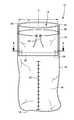
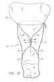
- FIG. 2Ashows a front sectional view of an embodiment of the apparatus, showing a view of the apparatus where the cross-wise axis L 2 of the inner conduit is aligned with the cross-wise axis of the outer chamber.
- FIG. 2Bshows a side sectional view of the embodiment shown in FIG. 2A , showing a side view of the inner conduit.
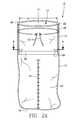
- FIG. 3shows close up view of the bottom of the inner conduit.
- FIG. 4shows a cross sectional view taken along lines 4 - 4 of FIG. 2 .
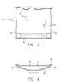
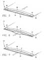
- FIGS. 5-7schematically show how the valve at the bottom of the inner conduit opens to allow material to flow through it in one direction ( FIGS. 5-6 ), but prevents flow in the opposite direction ( FIG. 7 ).
- FIG. 8shows a front sectional view of another embodiment of the apparatus, showing cruciate strips which may be utilized for maintaining the valve in a closed position.
- FIG. 9shows a side sectional view of the apparatus shown in FIG. 8 , after waste has been received, showing the attachment of the cruciate strips to the sides of the inner conduit and to the interior wall of the outer chamber.
- FIG. 10shows the same apparatus as in FIGS. 8-9 , but having a spill skirt attached at the top of the device.
- FIG. 1shows a prior art portable human waste receptacle 100
- FIGS. 2 through 10show various views of embodiments of the disclosed sealable and disposable waste receptacle 10 .
- the prior device 100 as shown in FIG. 1has a flexible lower bag 112 and a rigid upper plastic or similar material ring 114 that serves to retain the mouth 116 of the bag 112 in an open position.
- the ring 114could be removed to allow a medical practitioner to attempt to tie the bag shut or otherwise effect a closure of the bag following its intended use.
- the disclosed apparatus 10comprises a flexible outer layer formed from material which is impervious to water and the various waste materials which are placed in the device.
- the flexible outer layeris fashioned into an outer chamber 12 having an open top 14 and a closed bottom 16 .
- the outer chamber 12will typically be fashioned in the shape of a bag, cylinder, or similar shape having a longitudinal axis L 1 substantially larger than the cross-wise axis L 2 .
- the outer chamber 12further comprises a lower chamber 24 for receiving and storing waste.
- the walls of the outer chamber adjacent to the lower chamber 24may comprise various indicia 32 to indicate the volume of waste stored in the lower chamber to assist in ascertaining when the device is full.
- the apparatusfurther comprises an inner conduit 18 , fashioned from a flexible material, the top of which inner conduit may be flush with the top 14 of the outer chamber or which, alternatively, depends from the inside surface of the outer chamber 12 , typically near the open top of the outer chamber.
- the inner conduit 18is suspended within the outer chamber 12 .
- the top 20 of the inner conduit 18is circumferentially attached to the inside surface of the outer chamber 12 , forming a circumferential seal 22 at the point of attachment, such that the inner conduit provides a single pathway for waste material introduced into the top of the outer chamber into a lower chamber 24 located beneath the bottom 26 of the inner conduit 18 . Waste material W received into the apparatus 10 is received and maintained in the lower chamber 24 until such time as the receptacle is disposed.
- the peripheral edges at the top 20 of the inner conduit 18define the opening of the inner conduit.
- the peripheral edges at the top 20are fused or otherwise attached to the top of the outer chamber 12 or to the inside surface of the outer chamber sufficient to suspend the inner conduit 18 from the top of the outer chamber as shown in the various figures.
- the attachment means utilized to attach the top 20 of the inner conduit 18 to the inside surface of the outer chamber 12form a circumferential seal 22 , which is a liquid tight seal between the top of the inner conduit and the inside wall of the outer chamber 12 , such that material cannot escape from the device between the annulus 39 formed between the inner conduit 18 and the outer chamber 12 .
- the bottom 26 of inner conduit 18is sufficiently above the bottom of the lower chamber 24 to provide sufficient volume for storage of waste material M.
- the bottom 26 of the inner conduit 18is fashioned to function as a “valve” by the engagement and separation of its side walls 30 , 31 with respect to each other, the valve 28 permitting flow in one direction through the inner conduit into the lower chamber 24 .
- the normally closed valve 28is opened by the weight of waste W exerting a downward and sideways force at the bottom 26 of the inner conduit sufficient to overcome the biasing force keeping the valve closed.
- the valve 28restricts flow in the other direction, thus preventing the waste material W from flowing out of the lower chamber 24 back through the inner conduit 18 and spilling from the device.
- the inner conduit 18may be fashioned from the same type of material as the outer chamber 12 .
- the inner conduit 18may be fashioned from a single piece of material, or may be fashioned from a plurality of sheets 30 , 31 of material which are fused together along the longitudinal edges 36 of the material.
- the inner conduit 18may comprise two opposite facing sheets 30 , 31 of flexible material, each sheet having generally the same shape and dimensions.
- the sheets 30 , 31may be polygonal, including rectangular or trapezoidal, where the length-wise or longitudinal edges 36 of each sheet are fused to the length-wise edges of the opposing sheet.
- each sheet 30 , 31will not be attached to each other, such that an opening is defined at the top 20 of the inner conduit 18 , and valve 28 is fashioned from the bottom edges of the sheets 30 , 31 as described below.
- the opening of inner conduit 18may coincide with opening 14 of the outer chamber 12 .
- inner conduit 18may be placed lower within outer chamber 12 , such that the device has a greater volume of interim waste storage space before the waste W passes through valve 28 into the lower chamber 24 .
- the top 20 of the inner conduit 18will typically be in axial adjacency to the top 14 of the outer chamber 12 .
- the bottom 26 of the inner conduit 18comprises a biasing member 38 which attaches to the bottom edges of one of the sheets 31 , such that the biasing member is in compression.
- the biasing member 38may either be held in place by a pocket fashioned in the bottom edge of the sheet 31 or attached by thermal fusion or adhesive.
- the biasing member 38may be attached in such manner that it is removable from the inner conduit, such as by forming a pocket 40 on either side of the bottom edge of sheet 31 , as shown in FIGS. 3-4 .
- the biasing member 38urges the opening at the bottom of the inner conduit into the closed position by causing the bottom edge of the flexible sheet 31 to which it is attached to buckle. Because the opposing sheet 30 is attached or fused along its edges 36 to the sheet 31 having the biasing member 38 , the opposing wall 30 will also buckle in the same direction, thus urging the opening closed.
- Embodiments of the apparatus 10 ′may further comprise a pair of cruciate strips 42 , 44 .
- the end 45 of a first strip 42may be attached to the outside of the inner conduit member 18 ′ such as sheet 31 ′ and the end 47 of a second strip 43 may be attached to the outside of the other sheet 30 ′ of the inner conduit member 18 ′, both strips attached in relatively close proximity to the opening at the bottom 26 ′ of the inner conduit.
- the opposite end 49 of the first strip 42 and the opposite end 51 of the second strip 44extend below the bottom 26 ′ of the inner conduit 18 ′.
- the first strip 42crosses below the bottom 26 ′ of the inner conduit member 18 ′ and attaches to the inside wall of the opposite facing sheet of the outer chamber 12 ′.
- the second strip 44crosses below the bottom 26 ′ of the inner conduit member 18 ′ to the inside wall of the opposite facing sheet of the outer chamber 18 ′, such that the first and second strips cross below the 26 ′ bottom of the inner conduit member as shown in FIGS. 8-10 .
- the opposite facing walls of the outer chamber 12 ′will stretch, causing the cruciate strips 42 , 44 to also stretch, thereby pulling the bottom edges of the sheets 30 ′, 31 ′ of the inner conduit member 18 ′ closer together, thus improving the competency of the valve 28 ′ at the bottom of the inner conduit member.
- the outer chamber 12 , 12 ′will typically comprise closure means for sealing the receptacle and its contents and, to some extent, its odors.
- the closure meansmay concurrently seal the top edges of the inner conduit, by using closure means 46 , which may comprise adhesive tape 46 with removable backing 48 , hook and loop fasteners, or other known closure means.
- closure means 46may comprise adhesive tape 46 with removable backing 48 , hook and loop fasteners, or other known closure means.
- the closure meansmay also comprise a draw string 52 or tie which fits within a peripheral pocket around the perimeter of top 14 of the outer chamber 12 .
- the top 14 of the outer chamber 12may comprise a flexible skirt 50 affixed at the opening of the outer chamber, the skirt providing a “funnel” into the opening.
- the skirt 50may be shaped such that the device may be employed for a variety of services, such as incorporation into hospital gowns, diapers, underwear, shorts, pants, etc.
- the skirt 50may comprise its own closure means at its top to prevent the spilling of any waste which may have collected between the top of the skirt and the valve 28 ′.
- the devicemay further comprise a carrying handle which loops around the outer chamber to facilitate carrying the apparatus.
- the various components of the deviceare preferably fashioned from biodegradable plastics to facilitate responsible disposal of the waste material and the apparatus.
- the componentsmay also be fabricated from treated paper, foil or other materials appropriate for the use.
Landscapes
- Engineering & Computer Science (AREA)
- Mechanical Engineering (AREA)
- Processing Of Solid Wastes (AREA)
- Refuse Receptacles (AREA)
Abstract
Description
Claims (16)
Priority Applications (1)
| Application Number | Priority Date | Filing Date | Title |
|---|---|---|---|
| US12/750,567US8104960B2 (en) | 2009-03-30 | 2010-03-30 | Sealable and disposable receptacle for biologic waste products |
Applications Claiming Priority (2)
| Application Number | Priority Date | Filing Date | Title |
|---|---|---|---|
| US16478209P | 2009-03-30 | 2009-03-30 | |
| US12/750,567US8104960B2 (en) | 2009-03-30 | 2010-03-30 | Sealable and disposable receptacle for biologic waste products |
Publications (2)
| Publication Number | Publication Date |
|---|---|
| US20100278456A1 US20100278456A1 (en) | 2010-11-04 |
| US8104960B2true US8104960B2 (en) | 2012-01-31 |
Family
ID=43030403
Family Applications (1)
| Application Number | Title | Priority Date | Filing Date |
|---|---|---|---|
| US12/750,567Active - ReinstatedUS8104960B2 (en) | 2009-03-30 | 2010-03-30 | Sealable and disposable receptacle for biologic waste products |
Country Status (1)
| Country | Link |
|---|---|
| US (1) | US8104960B2 (en) |
Cited By (17)
| Publication number | Priority date | Publication date | Assignee | Title |
|---|---|---|---|---|
| US20110152801A1 (en)* | 2009-12-17 | 2011-06-23 | Klaus Michael Andreas Vollrath | Device for facilitating semen collection |
| US20110211776A1 (en)* | 2003-03-07 | 2011-09-01 | Conforti Carl J | Odor containment |
| US20130139474A1 (en)* | 2009-06-05 | 2013-06-06 | Todd Coleman | Sampling bag and funnel for collection of soils, muds, or other solids or liquids for subsequent analysis of headspace gases and other content |
| US20140233872A1 (en)* | 2013-02-18 | 2014-08-21 | Piper Stark | Odor Containing Temporary Storage Container for Disposal of Waste, Refuse, or Soiled Items |
| US20170209128A1 (en)* | 2016-01-27 | 2017-07-27 | Elizabeth P. Ohler | Bowel Care Collection Bag |
| US20200029674A1 (en)* | 2018-07-26 | 2020-01-30 | Cecelia Ann Mims | Method and apparatus for mixing beauty products |
| US11612305B1 (en) | 2014-06-06 | 2023-03-28 | Hyunsuk Lee | Receptacle for a laryngoscope and method of using same |
| US11786261B2 (en) | 2017-03-14 | 2023-10-17 | OrthAlign, Inc. | Soft tissue measurement and balancing systems and methods |
| US11820591B2 (en) | 2021-12-30 | 2023-11-21 | Woodrow Berry | Sanitary waste disposal device |
| US11871965B2 (en) | 2008-07-24 | 2024-01-16 | OrthAlign, Inc. | Systems and methods for joint replacement |
| US11903597B2 (en) | 2003-06-09 | 2024-02-20 | OrthAlign, Inc. | Surgical orientation system and method |
| US11911119B2 (en) | 2012-08-14 | 2024-02-27 | OrthAlign, Inc. | Hip replacement navigation system and method |
| US11951029B1 (en)* | 2019-07-29 | 2024-04-09 | Taylor P. Wilson | Flexible receptacles and flexible conduits for bodily fluids |
| US20240122280A1 (en)* | 2022-10-17 | 2024-04-18 | Caprice Dunbar | Waste receiving glove |
| US12232863B2 (en) | 2008-09-10 | 2025-02-25 | OrthAlign, Inc. | Hip surgery systems and methods |
| US12318313B2 (en) | 2009-07-24 | 2025-06-03 | OrthAlign, Inc. | Systems and methods for joint replacement |
| US12376972B2 (en) | 2015-02-20 | 2025-08-05 | OrthAlign, Inc. | Hip replacement navigation system and method |
Families Citing this family (4)
| Publication number | Priority date | Publication date | Assignee | Title |
|---|---|---|---|---|
| US7918836B2 (en)* | 2008-07-15 | 2011-04-05 | Zora Singh Gill | Ostomy bag with irrigation system |
| US20110280498A1 (en)* | 2010-05-11 | 2011-11-17 | Centurion Medical Products Corporation | Biodegradable waste container |
| US20120170873A1 (en)* | 2010-12-29 | 2012-07-05 | William Mathews | Utility Pouch Having a Self-Sealing Closure |
| EP3718517B1 (en)* | 2019-04-01 | 2023-03-22 | Hohmuth, Horst | Collecting device for offcuts |
Citations (17)
| Publication number | Priority date | Publication date | Assignee | Title |
|---|---|---|---|---|
| US1809259A (en)* | 1929-05-04 | 1931-06-09 | Harrison R Williams | Valve bag closure |
| US3189252A (en)* | 1962-09-21 | 1965-06-15 | United Inc | Plastic self-sealed valved container |
| US3403410A (en)* | 1966-06-01 | 1968-10-01 | Automatic Sprinkler Corp | Disposable urine container |
| US3471871A (en)* | 1967-01-31 | 1969-10-14 | Fairchild Hiller Corp | Waste collection bags |
| US3724461A (en)* | 1971-10-20 | 1973-04-03 | M Eisenberg | Container with self-closing one-way valve |
| US3797734A (en)* | 1972-02-04 | 1974-03-19 | R Fleury | Disposable bags |
| US3920179A (en)* | 1973-12-17 | 1975-11-18 | Kenneth F Hall | Disposable vomiting bag |
| US4990145A (en)* | 1989-02-07 | 1991-02-05 | Gkr Industries, Inc. | Disposable bag with hand protection |
| US5056932A (en)* | 1989-03-13 | 1991-10-15 | Young J Winslow | Disposable bag apparatus and method |
| US5067821A (en)* | 1990-04-27 | 1991-11-26 | Young J Winslow | Disposable bag apparatus and method |
| US5116139A (en)* | 1989-09-08 | 1992-05-26 | American Innotex, Inc. | Fluid containment bag |
| US5354132A (en)* | 1987-01-14 | 1994-10-11 | American Innotek, Inc. | Fluid containment bag |
| US5356398A (en)* | 1993-07-16 | 1994-10-18 | Laser Corporation | Disposable bag for the collection of body fluids |
| US5368583A (en)* | 1993-08-03 | 1994-11-29 | Gkr Industries, Inc. | Bodily fluid test kit |
| US6116780A (en)* | 1999-01-20 | 2000-09-12 | American Innotek, Inc. | Disposable toilet system |
| US20020193762A1 (en)* | 2001-06-18 | 2002-12-19 | Suydam Kristen V. | Disposable urinal system |
| US7530121B2 (en)* | 2005-09-21 | 2009-05-12 | Carolyn Snider | Portable disposable urination capture device system and method of using |
- 2010
- 2010-03-30USUS12/750,567patent/US8104960B2/enactiveActive - Reinstated
Patent Citations (17)
| Publication number | Priority date | Publication date | Assignee | Title |
|---|---|---|---|---|
| US1809259A (en)* | 1929-05-04 | 1931-06-09 | Harrison R Williams | Valve bag closure |
| US3189252A (en)* | 1962-09-21 | 1965-06-15 | United Inc | Plastic self-sealed valved container |
| US3403410A (en)* | 1966-06-01 | 1968-10-01 | Automatic Sprinkler Corp | Disposable urine container |
| US3471871A (en)* | 1967-01-31 | 1969-10-14 | Fairchild Hiller Corp | Waste collection bags |
| US3724461A (en)* | 1971-10-20 | 1973-04-03 | M Eisenberg | Container with self-closing one-way valve |
| US3797734A (en)* | 1972-02-04 | 1974-03-19 | R Fleury | Disposable bags |
| US3920179A (en)* | 1973-12-17 | 1975-11-18 | Kenneth F Hall | Disposable vomiting bag |
| US5354132A (en)* | 1987-01-14 | 1994-10-11 | American Innotek, Inc. | Fluid containment bag |
| US4990145A (en)* | 1989-02-07 | 1991-02-05 | Gkr Industries, Inc. | Disposable bag with hand protection |
| US5056932A (en)* | 1989-03-13 | 1991-10-15 | Young J Winslow | Disposable bag apparatus and method |
| US5116139A (en)* | 1989-09-08 | 1992-05-26 | American Innotex, Inc. | Fluid containment bag |
| US5067821A (en)* | 1990-04-27 | 1991-11-26 | Young J Winslow | Disposable bag apparatus and method |
| US5356398A (en)* | 1993-07-16 | 1994-10-18 | Laser Corporation | Disposable bag for the collection of body fluids |
| US5368583A (en)* | 1993-08-03 | 1994-11-29 | Gkr Industries, Inc. | Bodily fluid test kit |
| US6116780A (en)* | 1999-01-20 | 2000-09-12 | American Innotek, Inc. | Disposable toilet system |
| US20020193762A1 (en)* | 2001-06-18 | 2002-12-19 | Suydam Kristen V. | Disposable urinal system |
| US7530121B2 (en)* | 2005-09-21 | 2009-05-12 | Carolyn Snider | Portable disposable urination capture device system and method of using |
Cited By (23)
| Publication number | Priority date | Publication date | Assignee | Title |
|---|---|---|---|---|
| US20110211776A1 (en)* | 2003-03-07 | 2011-09-01 | Conforti Carl J | Odor containment |
| US11903597B2 (en) | 2003-06-09 | 2024-02-20 | OrthAlign, Inc. | Surgical orientation system and method |
| US11871965B2 (en) | 2008-07-24 | 2024-01-16 | OrthAlign, Inc. | Systems and methods for joint replacement |
| US12239344B2 (en) | 2008-07-24 | 2025-03-04 | OrthAlign, Inc. | Systems and methods for joint replacement |
| US12232863B2 (en) | 2008-09-10 | 2025-02-25 | OrthAlign, Inc. | Hip surgery systems and methods |
| US20130139474A1 (en)* | 2009-06-05 | 2013-06-06 | Todd Coleman | Sampling bag and funnel for collection of soils, muds, or other solids or liquids for subsequent analysis of headspace gases and other content |
| US10077139B2 (en)* | 2009-06-05 | 2018-09-18 | Weatherford Technology Holdings, Llc | Sampling bag and funnel for collection of soils, muds, or other solids or liquids for subsequent analysis of headspace gases and other content |
| US12318313B2 (en) | 2009-07-24 | 2025-06-03 | OrthAlign, Inc. | Systems and methods for joint replacement |
| US20110152801A1 (en)* | 2009-12-17 | 2011-06-23 | Klaus Michael Andreas Vollrath | Device for facilitating semen collection |
| US11911119B2 (en) | 2012-08-14 | 2024-02-27 | OrthAlign, Inc. | Hip replacement navigation system and method |
| US12433694B2 (en) | 2012-08-14 | 2025-10-07 | OrthAlign, Inc. | Hip replacement navigation system and method |
| US12144567B2 (en) | 2012-08-14 | 2024-11-19 | OrthAlign, Inc. | Hip replacement navigation system and method |
| US20140233872A1 (en)* | 2013-02-18 | 2014-08-21 | Piper Stark | Odor Containing Temporary Storage Container for Disposal of Waste, Refuse, or Soiled Items |
| US11612305B1 (en) | 2014-06-06 | 2023-03-28 | Hyunsuk Lee | Receptacle for a laryngoscope and method of using same |
| US12376972B2 (en) | 2015-02-20 | 2025-08-05 | OrthAlign, Inc. | Hip replacement navigation system and method |
| US10022108B2 (en)* | 2016-01-27 | 2018-07-17 | Elizabeth P. Ohler | Bowel care collection bag |
| US20170209128A1 (en)* | 2016-01-27 | 2017-07-27 | Elizabeth P. Ohler | Bowel Care Collection Bag |
| US11786261B2 (en) | 2017-03-14 | 2023-10-17 | OrthAlign, Inc. | Soft tissue measurement and balancing systems and methods |
| US10945507B2 (en)* | 2018-07-26 | 2021-03-16 | Cecelia Ann Mims | Method and apparatus for mixing beauty products |
| US20200029674A1 (en)* | 2018-07-26 | 2020-01-30 | Cecelia Ann Mims | Method and apparatus for mixing beauty products |
| US11951029B1 (en)* | 2019-07-29 | 2024-04-09 | Taylor P. Wilson | Flexible receptacles and flexible conduits for bodily fluids |
| US11820591B2 (en) | 2021-12-30 | 2023-11-21 | Woodrow Berry | Sanitary waste disposal device |
| US20240122280A1 (en)* | 2022-10-17 | 2024-04-18 | Caprice Dunbar | Waste receiving glove |
Also Published As
| Publication number | Publication date |
|---|---|
| US20100278456A1 (en) | 2010-11-04 |
Similar Documents
| Publication | Publication Date | Title |
|---|---|---|
| US8104960B2 (en) | Sealable and disposable receptacle for biologic waste products | |
| US6115855A (en) | Disposable biodegradable potty liner | |
| US5647670A (en) | Body fluid containment bag | |
| US6070275A (en) | Portable urine holding system | |
| US6918898B2 (en) | Closed drainage system for irrigating ostomies | |
| EP2120814A2 (en) | A collecting system suitable for collecting and disposing of bodily waste materials | |
| KR20140008417A (en) | Disposal-bag system for a disposable object | |
| EP1904006A1 (en) | Receptacle and method for disposing of bodily waste materials | |
| US20120008877A1 (en) | Bag with sealing device and collar for disposing of waste | |
| US7615038B2 (en) | Disposable diaper with sealable enclosure and method for sealing and disposing of the same | |
| US8518003B2 (en) | Sanitary waste disposal apparatus and method | |
| CN101778775B (en) | A bag with a seal and a collar for disposal of garbage | |
| GB2470765A (en) | Organic waste liner with double closure arrangement | |
| US20090044326A1 (en) | Disposable commode chair liner | |
| US20080310767A1 (en) | Expandable Emesis Containment System and Use Thereof | |
| US20020049416A1 (en) | Disposable bag for storing excrement and solid and liquid residues for use in hospital containers | |
| US20160229595A1 (en) | Disposible waste bag | |
| US20070083179A1 (en) | Used tampon and condom personal disposal | |
| US20100175179A1 (en) | Infant training item | |
| EP2878286A1 (en) | Portable container for holding liquids and also for urination, especially for females | |
| US20150231039A1 (en) | Apparatus for Containing Regurgitation | |
| US20120204518A1 (en) | Disposal system and method for disposable items | |
| WO2006116539A2 (en) | Diaper with waste receptacle | |
| US20160101000A1 (en) | Disposable Foil Lined Personal Bag | |
| US20140233872A1 (en) | Odor Containing Temporary Storage Container for Disposal of Waste, Refuse, or Soiled Items |
Legal Events
| Date | Code | Title | Description |
|---|---|---|---|
| STCF | Information on status: patent grant | Free format text:PATENTED CASE | |
| REMI | Maintenance fee reminder mailed | ||
| FPAY | Fee payment | Year of fee payment:4 | |
| SULP | Surcharge for late payment | ||
| FEPP | Fee payment procedure | Free format text:MAINTENANCE FEE REMINDER MAILED (ORIGINAL EVENT CODE: REM.); ENTITY STATUS OF PATENT OWNER: SMALL ENTITY | |
| LAPS | Lapse for failure to pay maintenance fees | Free format text:PATENT EXPIRED FOR FAILURE TO PAY MAINTENANCE FEES (ORIGINAL EVENT CODE: EXP.); ENTITY STATUS OF PATENT OWNER: SMALL ENTITY | |
| FP | Lapsed due to failure to pay maintenance fee | Effective date:20200131 | |
| PRDP | Patent reinstated due to the acceptance of a late maintenance fee | Effective date:20200421 | |
| FEPP | Fee payment procedure | Free format text:PETITION RELATED TO MAINTENANCE FEES GRANTED (ORIGINAL EVENT CODE: PMFG); ENTITY STATUS OF PATENT OWNER: MICROENTITY Free format text:PETITION RELATED TO MAINTENANCE FEES FILED (ORIGINAL EVENT CODE: PMFP); ENTITY STATUS OF PATENT OWNER: MICROENTITY Free format text:SURCHARGE, PETITION TO ACCEPT PYMT AFTER EXP, UNINTENTIONAL (ORIGINAL EVENT CODE: M3558); ENTITY STATUS OF PATENT OWNER: MICROENTITY Free format text:ENTITY STATUS SET TO MICRO (ORIGINAL EVENT CODE: MICR); ENTITY STATUS OF PATENT OWNER: MICROENTITY | |
| MAFP | Maintenance fee payment | Free format text:PAYMENT OF MAINTENANCE FEE, 8TH YEAR, MICRO ENTITY (ORIGINAL EVENT CODE: M3552); ENTITY STATUS OF PATENT OWNER: MICROENTITY Year of fee payment:8 | |
| STCF | Information on status: patent grant | Free format text:PATENTED CASE | |
| FEPP | Fee payment procedure | Free format text:MAINTENANCE FEE REMINDER MAILED (ORIGINAL EVENT CODE: REM.); ENTITY STATUS OF PATENT OWNER: MICROENTITY | |
| FEPP | Fee payment procedure | Free format text:SURCHARGE FOR LATE PAYMENT, MICRO ENTITY (ORIGINAL EVENT CODE: M3556); ENTITY STATUS OF PATENT OWNER: MICROENTITY | |
| MAFP | Maintenance fee payment | Free format text:PAYMENT OF MAINTENANCE FEE, 12TH YEAR, MICRO ENTITY (ORIGINAL EVENT CODE: M3553); ENTITY STATUS OF PATENT OWNER: MICROENTITY Year of fee payment:12 |