US8104770B2 - Semiconductor process chamber - Google Patents
Semiconductor process chamberDownload PDFInfo
- Publication number
- US8104770B2 US8104770B2US12/024,187US2418708AUS8104770B2US 8104770 B2US8104770 B2US 8104770B2US 2418708 AUS2418708 AUS 2418708AUS 8104770 B2US8104770 B2US 8104770B2
- Authority
- US
- United States
- Prior art keywords
- lid
- container
- process chamber
- processing space
- metallic element
- Prior art date
- Legal status (The legal status is an assumption and is not a legal conclusion. Google has not performed a legal analysis and makes no representation as to the accuracy of the status listed.)
- Expired - Fee Related, expires
Links
- 238000000034methodMethods0.000titleclaimsabstractdescription31
- 239000004065semiconductorSubstances0.000titledescription5
- 229910052751metalInorganic materials0.000claimsabstractdescription61
- 239000000758substrateSubstances0.000claimsdescription11
- 238000007906compressionMethods0.000claimsdescription8
- 230000006835compressionEffects0.000claimsdescription7
- 238000011144upstream manufacturingMethods0.000claimsdescription5
- 230000000694effectsEffects0.000claimsdescription3
- 238000003780insertionMethods0.000claims2
- 230000037431insertionEffects0.000claims2
- 238000006243chemical reactionMethods0.000abstractdescription3
- 238000007789sealingMethods0.000description5
- 238000004519manufacturing processMethods0.000description4
- 239000000463materialSubstances0.000description4
- -1polytetrafluoroethylenePolymers0.000description4
- 239000002245particleSubstances0.000description3
- 235000012431wafersNutrition0.000description3
- PXHVJJICTQNCMI-UHFFFAOYSA-NNickelChemical compound[Ni]PXHVJJICTQNCMI-UHFFFAOYSA-N0.000description2
- 229910052782aluminiumInorganic materials0.000description2
- XAGFODPZIPBFFR-UHFFFAOYSA-NaluminiumChemical compound[Al]XAGFODPZIPBFFR-UHFFFAOYSA-N0.000description2
- 230000007423decreaseEffects0.000description2
- 150000002500ionsChemical class0.000description2
- 229910001369BrassInorganic materials0.000description1
- RYGMFSIKBFXOCR-UHFFFAOYSA-NCopperChemical compound[Cu]RYGMFSIKBFXOCR-UHFFFAOYSA-N0.000description1
- 239000004812Fluorinated ethylene propyleneSubstances0.000description1
- 239000004677NylonSubstances0.000description1
- 229920001774PerfluoroetherPolymers0.000description1
- 239000004698PolyethyleneSubstances0.000description1
- 239000004743PolypropyleneSubstances0.000description1
- 239000004793PolystyreneSubstances0.000description1
- 229910000831SteelInorganic materials0.000description1
- RTAQQCXQSZGOHL-UHFFFAOYSA-NTitaniumChemical compound[Ti]RTAQQCXQSZGOHL-UHFFFAOYSA-N0.000description1
- 229910045601alloyInorganic materials0.000description1
- 239000000956alloySubstances0.000description1
- 230000004075alterationEffects0.000description1
- 230000000712assemblyEffects0.000description1
- 238000000429assemblyMethods0.000description1
- 239000010951brassSubstances0.000description1
- 238000004140cleaningMethods0.000description1
- 230000003749cleanlinessEffects0.000description1
- 239000002131composite materialSubstances0.000description1
- 239000000356contaminantSubstances0.000description1
- 229910052802copperInorganic materials0.000description1
- 239000010949copperSubstances0.000description1
- 230000008021depositionEffects0.000description1
- 230000006866deteriorationEffects0.000description1
- 238000009792diffusion processMethods0.000description1
- 238000005530etchingMethods0.000description1
- 238000005468ion implantationMethods0.000description1
- 239000000203mixtureSubstances0.000description1
- 238000012986modificationMethods0.000description1
- 230000004048modificationEffects0.000description1
- 229910052759nickelInorganic materials0.000description1
- NJPPVKZQTLUDBO-UHFFFAOYSA-NnovaluronChemical compoundC1=C(Cl)C(OC(F)(F)C(OC(F)(F)F)F)=CC=C1NC(=O)NC(=O)C1=C(F)C=CC=C1FNJPPVKZQTLUDBO-UHFFFAOYSA-N0.000description1
- 229920001778nylonPolymers0.000description1
- 230000003647oxidationEffects0.000description1
- 238000007254oxidation reactionMethods0.000description1
- 229920009441perflouroethylene propylenePolymers0.000description1
- 210000002381plasmaAnatomy0.000description1
- 229920002492poly(sulfone)Polymers0.000description1
- 229920000573polyethylenePolymers0.000description1
- 229920000642polymerPolymers0.000description1
- 229920001155polypropylenePolymers0.000description1
- 229920002223polystyrenePolymers0.000description1
- 229920001343polytetrafluoroethylenePolymers0.000description1
- 239000004810polytetrafluoroethyleneSubstances0.000description1
- 238000004904shorteningMethods0.000description1
- 239000010935stainless steelSubstances0.000description1
- 229910001220stainless steelInorganic materials0.000description1
- 239000010959steelSubstances0.000description1
- 239000010936titaniumSubstances0.000description1
- 229910052719titaniumInorganic materials0.000description1
- 229920002554vinyl polymerPolymers0.000description1
Images


Classifications
- H—ELECTRICITY
- H01—ELECTRIC ELEMENTS
- H01L—SEMICONDUCTOR DEVICES NOT COVERED BY CLASS H10
- H01L21/00—Processes or apparatus adapted for the manufacture or treatment of semiconductor or solid state devices or of parts thereof
- H01L21/67—Apparatus specially adapted for handling semiconductor or electric solid state devices during manufacture or treatment thereof; Apparatus specially adapted for handling wafers during manufacture or treatment of semiconductor or electric solid state devices or components ; Apparatus not specifically provided for elsewhere
- H01L21/67005—Apparatus not specifically provided for elsewhere
- H01L21/67011—Apparatus for manufacture or treatment
- H01L21/67126—Apparatus for sealing, encapsulating, glassing, decapsulating or the like
- Y—GENERAL TAGGING OF NEW TECHNOLOGICAL DEVELOPMENTS; GENERAL TAGGING OF CROSS-SECTIONAL TECHNOLOGIES SPANNING OVER SEVERAL SECTIONS OF THE IPC; TECHNICAL SUBJECTS COVERED BY FORMER USPC CROSS-REFERENCE ART COLLECTIONS [XRACs] AND DIGESTS
- Y10—TECHNICAL SUBJECTS COVERED BY FORMER USPC
- Y10S—TECHNICAL SUBJECTS COVERED BY FORMER USPC CROSS-REFERENCE ART COLLECTIONS [XRACs] AND DIGESTS
- Y10S277/00—Seal for a joint or juncture
- Y10S277/913—Seal for fluid pressure below atmospheric, e.g. vacuum
- Y—GENERAL TAGGING OF NEW TECHNOLOGICAL DEVELOPMENTS; GENERAL TAGGING OF CROSS-SECTIONAL TECHNOLOGIES SPANNING OVER SEVERAL SECTIONS OF THE IPC; TECHNICAL SUBJECTS COVERED BY FORMER USPC CROSS-REFERENCE ART COLLECTIONS [XRACs] AND DIGESTS
- Y10—TECHNICAL SUBJECTS COVERED BY FORMER USPC
- Y10S—TECHNICAL SUBJECTS COVERED BY FORMER USPC CROSS-REFERENCE ART COLLECTIONS [XRACs] AND DIGESTS
- Y10S277/00—Seal for a joint or juncture
- Y10S277/935—Seal made of a particular material
- Y10S277/939—Containing metal
- Y—GENERAL TAGGING OF NEW TECHNOLOGICAL DEVELOPMENTS; GENERAL TAGGING OF CROSS-SECTIONAL TECHNOLOGIES SPANNING OVER SEVERAL SECTIONS OF THE IPC; TECHNICAL SUBJECTS COVERED BY FORMER USPC CROSS-REFERENCE ART COLLECTIONS [XRACs] AND DIGESTS
- Y10—TECHNICAL SUBJECTS COVERED BY FORMER USPC
- Y10S—TECHNICAL SUBJECTS COVERED BY FORMER USPC CROSS-REFERENCE ART COLLECTIONS [XRACs] AND DIGESTS
- Y10S277/00—Seal for a joint or juncture
- Y10S277/935—Seal made of a particular material
- Y10S277/944—Elastomer or plastic
- Y—GENERAL TAGGING OF NEW TECHNOLOGICAL DEVELOPMENTS; GENERAL TAGGING OF CROSS-SECTIONAL TECHNOLOGIES SPANNING OVER SEVERAL SECTIONS OF THE IPC; TECHNICAL SUBJECTS COVERED BY FORMER USPC CROSS-REFERENCE ART COLLECTIONS [XRACs] AND DIGESTS
- Y10—TECHNICAL SUBJECTS COVERED BY FORMER USPC
- Y10S—TECHNICAL SUBJECTS COVERED BY FORMER USPC CROSS-REFERENCE ART COLLECTIONS [XRACs] AND DIGESTS
- Y10S414/00—Material or article handling
- Y10S414/135—Associated with semiconductor wafer handling
- Y10S414/139—Associated with semiconductor wafer handling including wafer charging or discharging means for vacuum chamber
- Y—GENERAL TAGGING OF NEW TECHNOLOGICAL DEVELOPMENTS; GENERAL TAGGING OF CROSS-SECTIONAL TECHNOLOGIES SPANNING OVER SEVERAL SECTIONS OF THE IPC; TECHNICAL SUBJECTS COVERED BY FORMER USPC CROSS-REFERENCE ART COLLECTIONS [XRACs] AND DIGESTS
- Y10—TECHNICAL SUBJECTS COVERED BY FORMER USPC
- Y10T—TECHNICAL SUBJECTS COVERED BY FORMER US CLASSIFICATION
- Y10T29/00—Metal working
- Y10T29/49—Method of mechanical manufacture
- Y10T29/49718—Repairing
- Y10T29/49719—Seal or element thereof
Definitions
- a semiconductor process chambercommonly comprises a container, a lid, and a seal that seals the interface therebetween.
- the lidis usually convertible between a condition whereat it seals the access opening into the processing space, and a condition whereat the access opening is uncovered for loading/unloading of the processing space.
- the container's interface surface and/or the lid's interface surfacecan include a circumferential groove in which the seal is situated.
- ultra-high-vacuumpressures lower than about 10 ⁇ 7 pascal and/or 10 ⁇ 9 torr
- UHPultra-high-purity
- these manufacturing methodscan involve repeated opening and sealing process chambers so that substrates (e.g., wafers) can be continuously loaded, processed, and then unloaded therefrom.
- Slow production ratese.g., caused by long pump-down times
- significant equipment downtimee.g., for seal replacement or interface cleaning
- substandard yieldse.g., due to particle generation
- a sealcomprises an elastomeric element and a metallic element that can seal the container-lid interface of a process chamber.
- the sealcan be constructed to achieve ultra high vacuum levels without compromising on cleanliness, and still allow a clamped (rather than bolted) container-lid interface.
- the sealcan efficiently be used in UHV and/or UHP processing chambers with unbolted and/or dynamic interfaces.
- the elastomeric element and the metallic elementcan be arranged and adapted to seal the chamber's interface sequentially during its conversion to a sealed condition.
- the elastomeric elementcreates a seal during early evacuation stages, with the help of a clamping device. This maintains the chamber's vacuum, so that pressure differential can continue to rise, and provide the sealing load necessary for the metallic element to create a seal.
- the composite sealcapitalizes on the low-sealing-load ability of elastomeric element, while still providing a metallic seal during high pressure differential periods.
- the elastomeric element and the metallic elementcan be arranged and adapted to seal the chamber's interface in series when processing chamber is in its sealed condition.
- the metallic elementcan be positioned upstream of the elastomeric element relative to the processing chamber. (In cylindrical processing chambers, for example, the metallic element can be positioned radially inward of the elastomeric element.) In this manner, the metallic element shields the elastomeric element from gas permeation, thermal exposure, and reactive plasmas, and/or ion-impingement.
- the metallic elementcan also shield the processing chamber from particles generated by the elastomeric element.
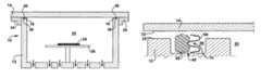
- FIG. 1Ais a schematic view of a process chamber comprising a container and a lid, the lid being shown in its sealed condition.
- FIG. 1Bis a schematic view of a process chamber comprising a container and a lid, the lid being shown in its load/unload condition.
- FIG. 1Cis a close-up of a groove in the container-lid interface, the groove having a rectangular cross-section shape.
- FIG. 1Dis a close-up of a groove in the container-lid interface, the groove, having a trapezoidal cross-section shape.
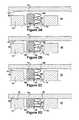
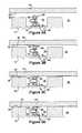
- FIGS. 2A-2D , 3 A- 3 D, 4 A- 4 D, 5 A- 5 D, 6 A- 6 D, 7 A- 7 D, and 8 A- 8 Dare 2 nd -8 th drawing sets showing the seal's contact with, and compression by, interfacing surfaces of the lid and container.
- FIGS. 7E and 7Fshow two possible forms a spring which can be used with the seal shown in FIGS. 7A-7D .
- a process chamber 10comprises a container 12 , a lid 14 , and an interface 16 therebetween.
- the container 12defines a processing space 20 (and an access opening 22 thereinto).
- the lid 14is convertible between a sealed condition ( FIG. 1A ), whereat it seals the access opening 22 into the processing space 20 , and a loading/unloading condition ( FIG. 1B ), whereat the access opening 22 is uncovered.
- the process chamber 10can be an ultra-high-vacuum (UHV) and/or ultra-high-purity (UHP) chamber which is part of a semiconductor manufacturing process.
- UHVultra-high-vacuum
- UHPultra-high-purity
- the substrate 24e.g., a wafer
- the interface 16is sealed, the substrate 24 can be processed within the container 12 .
- the processingcan comprise photo-masking, deposition, oxidation, nitridation, ion implantation, diffusion, and/or etching.
- the vacuumcan be released within the processing space 20 , and the lid can be converted from its sealed condition to its load-unload condition.
- the substrate 24can be withdrawn from the processing space 20 (through the access opening 22 ) and the steps repeated for the next substrate (e.g., the next wafer in the processing line).
- the container 12includes an interface surface 30 surrounding the access opening 22 and the lid 14 includes an interface surface 32 seated against the container's interface surface 30 when in its sealed condition. These surfaces 30 / 32 together define the interface 16 between the container 12 and the lid 14 .
- a clamp 34(or other suitable means) can be provided to brace, lock, or otherwise hold the lid 14 against the container 12 .
- the container's interface surface 30 and/or the lid's interface surface 32includes at least one groove 36 .
- the grooves 36have a rectangular cross-sectional shapes. But, the groove 36 can have such a rectangular cross-section shape ( FIG. 1C ), a trapezoidal cross-section shape ( FIG. 1D ), or any other suitable cross-section shape.
- the groove 36is continuous around the rim (e.g, perimeter, circumference) surrounding the processing chamber 20 and/or the access opening 22 .
- a seal 40is situated in the groove 36 .
- the seal 40has a generally ring-like shape, so as to be seated in the continuous groove 36 .
- the seal 40can generally comprises an elastomeric element 50 and a metallic element 60 .
- the elastomeric element 50can be made from polymeric materials including nylon, polytetrafluoroethylene, fluorinated ethylene-propylene, chlorotrifluoroethylene, perfluoroalkoxy polymer, polyvinyls, polyethylene, polypropylene, polystyrene, polysulfone and the like.
- the metallic element 60can be made from aluminum, steel, stainless steel, copper, brass, titanium, nickel, and alloys thereof.
- the elastomeric element 50 and the metallic element 60can be arranged and adapted to seal the chamber's interface 16 sequentially during conversion to the sealed condition.
- the seal 40can be designed so that the uncompressed height h 1 of the elastomeric element 50 is greater than the uncompressed height h 2 of the metallic element 60 . (See A figures in 2 nd -7 th drawing sets.) This height difference can result in the elastomeric element 50 being contacted and compressed prior to contact-compression of the metallic element 60 .
- the elastomeric element 50When converting the lid 14 to the sealed condition, the elastomeric element 50 is first contacted by the lid 14 (See B figures in 2 nd -7 th drawing sets). Thereafter, possibly with the help of the clamp 34 , the elastomeric element 50 is compressed. (See C figures in 2 nd -7 th drawing sets.)
- the clamp 34need only be sufficient to compress the elastomeric element 50 (not the metallic element 60 ), whereby an easily removable, and/or manually operable, clamping arrangement can be used.
- the elastomeric element 50creates a seal during early evacuation stages, thereby allowing the vacuum to continue to build in the processing chamber 20 . As the pressure differential rises, it creates a sealing load sufficient to compress the metallic element 60 . (See D figures in 2 nd -7 th drawing sets.)
- the elastomeric element 50 and the metallic element 60can be arranged and adapted to seal the chamber's interface 16 in series when processing chamber 20 is in a sealed condition. And the metallic element 60 can be situated to encounter processing activity upstream of the elastomeric element 50 . In the illustrated embodiment, this upstream-orientation results in the metallic element 60 being positioned radially inward from the elastomeric element 50 .
- the metallic element 60(which can be made of a material impervious to gas within the processing space 20 ) functions as a shield to protect the elastomeric element 50 from gas permeation. The metallic element 60 also shields the elastomeric element 50 from direct impingement of high energy or ions. In some cases, the metallic element 60 can also function to energize the elastomeric element 50 .
- the elastomeric member 50can have a roughly rectangular cross-section shape with its groove-ceiling side and/or its groove-floor side having a snubbed profile.
- the metallic element 60can have a W-like cross-section shape, with ceiling-floor arms which reach towards the elastomeric element 50 and middle arms which extend the opposite direction.
- the middle armsform a central compression cavity 70 opening towards the processing space 20 .
- the metal-contacting portion of the elastomeric element 50can have a recess for receiving the central curve of the W.
- the seal's elastomeric member 50 and its metallic element 60can each be in an uncompressed condition.
- the height h e of the elastomeric memberwill 50 will represent its uncompressed height h 1 and the height h m of the metallic member 60 will represent its uncompressed height h 2 . If h 1 and h 2 are greater than the groove's height h g , they will project beyond the groove's ceiling plane. (See FIG. 2A .) As the lid 14 is moved towards its sealed condition, the container-lid gap decreases.
- the lid's interfacing surface 32will first contact the elastomeric member 50 .
- the process chamber 10can (or cannot) be designed so that this first-seal-contact condition is accomplishable manually with the clamp 34 . In any event, this allows a vacuum to build within the processing chamber 20 thereby further pulling the lid 14 towards the container's interfacing surface 30 .
- the elastomeric member 50is compressed and the metallic element 60 is contacted.
- FIG. 2CAs the evacuation of the processing space 20 continues, and the container-lid gap closes, the elastomeric element 50 is further compressed until its height h e corresponds to the groove's height h g .
- the now-contacted metallic member 60is also compressed until its height h m corresponds to the groove's height he. (See FIG. 2D .)
- the metallic element 60forms a radial shield around the inner circumference of the elastomeric element 50 .
- the seal 40can comprise two elastomeric elements 50 which, for example, each have a circular cross-section.
- the metallic element 60has a flanged-omega cross-sectional shape with a central compression cavity opening and a pair of ceiling-floor arms.
- the central compression cavity 70opens towards the processing space 20 and the elastomeric elements 50 are positioned on either side thereof.
- the metallic element 60forms a radially inward shield for the elastomeric elements 50 .
- the elastomeric elements 50are compressed before the metallic element 60 and, when the lid 14 is in its sealed condition ( FIG. 3D ), the metallic element 60 forms a shield in front of the elastomeric elements 50 .
- the height h eis measured from the bottom of the lower elastomeric member 50 to the top of the upper elastomeric member 50 .
- the seal 40can comprise two elastomeric elements 50 , a W-shape metallic element 60 , and a retainer element 80 .
- the elastomeric elements 50can each have, for example, a circular cross-section shape in non-compressed state, and the retainer element 80 can have a T cross-section shape.
- the elastomeric elements 50are positioned on the groove-ceiling side and the groove-floor side of the retainer element 80 , on either side of the T's stem.
- the metallic element 60is positioned adjacent the T's head, with the central curve of the W seating on the retainer member 80 .
- the retainer element 80(which can be made of aluminum or any other suitable material) does not necessarily compress during the sealing steps, but rather retains the other components during their compression. In this embodiment, both the metallic element 60 and the retainer element 80 shield the elastomeric elements 50 from processing effects.
- the elastomeric element 50 and the metallic element 60can have similar cross-sectional shapes, such as the illustrated cut-off-tear-drop cross-sectional shape.
- the elastomeric element 50can straddle downstream side of the metallic element 60 and it can be bonded thereto (or a completely separate piece).
- the metallic element 60can have a central compression cavity opening towards the processing space. The elastomeric element 50 will compress prior to the metallic element 60 during sealing steps. And although upstream ceiling-floor portions of the elastomeric element 50 may be exposed to processing steps, the metallic element 60 will shield the rest of the element 50 therefrom.
- the seal 40can further include an energizing element 90 such as a coiled spring ( FIG. 7E ) or a cut tube ( FIG. 7F ). If the energizing element 90 occupies a radially inward portion of the seal 40 , it can also be made of a metallic or other gas impervious material. A radially-inward element 90 can aid the metallic element 60 in shielding the elastomeric element 50 .
- an energizing element 90such as a coiled spring ( FIG. 7E ) or a cut tube ( FIG. 7F ). If the energizing element 90 occupies a radially inward portion of the seal 40 , it can also be made of a metallic or other gas impervious material. A radially-inward element 90 can aid the metallic element 60 in shielding the elastomeric element 50 .
- the elastomeric element 50 and the metallic element 60were shown positioned within the same groove 36 .
- FIGS. 8A-8Dseparate groove-situating is also possible.
- the container's interface surface 30 and/or the lid's interface surface 32can have two grooves 36 and 38 concentrically arranged relative to the processing space 20 .
- the elastomeric element 50(which can have a circular cross-section shape) is positioned in the groove most remote from the processing space 20 and the metallic element 60 (which can have a W cross-section shape) is positioned in the closer groove.
- the container 12can further comprise an evacuation conduit 37 between the two grooves 36 and 38 , which is sealed upon
- the metallic element 60can function as a shield to protect the elastomeric element 50 from gas permeation, ion impingement, chemically corrosive vapors, and other life-shortening enemies. That being said, the elastomeric member 50 may need replacement before, and/or more often, than the metallic element 60 . In many designs (see e.g., the seal 40 in the 2 nd -5 th and 8 th drawing sets) the elastomeric element 50 can be replaced, with or without replacement of the metallic member 60 .
- the seal 40can be designed by optimizing parameters including the stiffness value of the elastomeric element 50 , the stiffness value of the metallic element 60 , the uncompressed height h 1 of the elastomeric element, the uncompressed height h 2 of the metallic element 60 , and the initial gap distance g between the interfacing surfaces.
- the optimizing stepcan comprise, for example, finite element analysis (FEA).
Landscapes
- Engineering & Computer Science (AREA)
- Physics & Mathematics (AREA)
- Condensed Matter Physics & Semiconductors (AREA)
- General Physics & Mathematics (AREA)
- Manufacturing & Machinery (AREA)
- Computer Hardware Design (AREA)
- Microelectronics & Electronic Packaging (AREA)
- Power Engineering (AREA)
- Gasket Seals (AREA)
- Closures For Containers (AREA)
Abstract
Description
Claims (16)
Priority Applications (1)
| Application Number | Priority Date | Filing Date | Title |
|---|---|---|---|
| US12/024,187US8104770B2 (en) | 2007-02-01 | 2008-02-01 | Semiconductor process chamber |
Applications Claiming Priority (4)
| Application Number | Priority Date | Filing Date | Title |
|---|---|---|---|
| US88763007P | 2007-02-01 | 2007-02-01 | |
| US90821707P | 2007-03-27 | 2007-03-27 | |
| US94965707P | 2007-07-13 | 2007-07-13 | |
| US12/024,187US8104770B2 (en) | 2007-02-01 | 2008-02-01 | Semiconductor process chamber |
Publications (2)
| Publication Number | Publication Date |
|---|---|
| US20080187430A1 US20080187430A1 (en) | 2008-08-07 |
| US8104770B2true US8104770B2 (en) | 2012-01-31 |
Family
ID=39472609
Family Applications (1)
| Application Number | Title | Priority Date | Filing Date |
|---|---|---|---|
| US12/024,187Expired - Fee RelatedUS8104770B2 (en) | 2007-02-01 | 2008-02-01 | Semiconductor process chamber |
Country Status (2)
| Country | Link |
|---|---|
| US (1) | US8104770B2 (en) |
| EP (1) | EP1953802A3 (en) |
Cited By (6)
| Publication number | Priority date | Publication date | Assignee | Title |
|---|---|---|---|---|
| US20110076848A1 (en)* | 2009-06-30 | 2011-03-31 | Amitava Datta | Semiconductor process chamber and seal |
| US9859142B2 (en) | 2011-10-20 | 2018-01-02 | Lam Research Corporation | Edge seal for lower electrode assembly |
| US9869392B2 (en) | 2011-10-20 | 2018-01-16 | Lam Research Corporation | Edge seal for lower electrode assembly |
| US10090211B2 (en) | 2013-12-26 | 2018-10-02 | Lam Research Corporation | Edge seal for lower electrode assembly |
| US20210254716A1 (en)* | 2020-02-19 | 2021-08-19 | Saint-Gobain Performance Plastics Corporation | Flexible cryogenic seal |
| US11749549B2 (en)* | 2019-03-15 | 2023-09-05 | Kctech Co., Ltd. | Substrate processing apparatus with an air curtain in a loading/unloading part |
Families Citing this family (10)
| Publication number | Priority date | Publication date | Assignee | Title |
|---|---|---|---|---|
| JP2010199569A (en)* | 2009-02-02 | 2010-09-09 | Sumco Corp | Method of manufacturing simox wafer |
| JP5708506B2 (en)* | 2011-04-20 | 2015-04-30 | 東京エレクトロン株式会社 | Processing equipment |
| KR102193030B1 (en)* | 2013-12-03 | 2020-12-18 | 세메스 주식회사 | Sealing assembly and substrate treating apparatus and substrate treating method |
| KR102157837B1 (en)* | 2013-12-31 | 2020-09-18 | 세메스 주식회사 | Substrate treating apparatus and substrate treating method |
| US10830357B2 (en)* | 2015-04-24 | 2020-11-10 | Raytheon Technologies Corporation | Single crystal grain structure seals and method of forming |
| JP7250311B2 (en)* | 2016-04-01 | 2023-04-03 | モ カン,ジューン | Carrier head for chemical-mechanical polishing apparatus with substrate receiving member |
| CN109155267B (en)* | 2016-05-06 | 2024-01-26 | 精密聚合物工程有限公司 | Elastic sealing element |
| US10487943B2 (en)* | 2016-07-12 | 2019-11-26 | United Technologies Corporation | Multi-ply seal ring |
| KR102041308B1 (en) | 2017-09-27 | 2019-11-27 | 세메스 주식회사 | Apparatus and Method for treating substrate |
| KR102277809B1 (en)* | 2019-07-15 | 2021-07-14 | 세메스 주식회사 | Unit for supporting substrate and system for treating substrate with the unit |
Citations (28)
| Publication number | Priority date | Publication date | Assignee | Title |
|---|---|---|---|---|
| US3248119A (en)* | 1963-09-19 | 1966-04-26 | Pennsalt Chemicals Corp | High vacuum seal |
| US3375016A (en)* | 1964-03-09 | 1968-03-26 | Navy Usa | Two-stage seal arrangement |
| US3765647A (en)* | 1972-01-21 | 1973-10-16 | M & J Valve Co | Valve construction and method |
| US4029294A (en)* | 1974-10-04 | 1977-06-14 | Mcevoy Oilfield Equipment Co. | High pressure valve |
| US4053085A (en)* | 1975-10-10 | 1977-10-11 | Block Engineering, Inc. | Dissimilar materials seal for high pressure, high temperature and chemically reactive environments |
| US4109922A (en)* | 1976-04-28 | 1978-08-29 | Soudure Autogene Francaise | Sealing device for a vacuum enclosure |
| US4163544A (en)* | 1977-11-10 | 1979-08-07 | Acf Industries, Incorporated | Two piece composite valve seal ring construction |
| US4551310A (en)* | 1980-07-30 | 1985-11-05 | Hitachi, Ltd. | Continuous vacuum treating apparatus |
| US4831212A (en) | 1986-05-09 | 1989-05-16 | Nissin Electric Company, Limited | Package for packing semiconductor devices and process for producing the same |
| US5368648A (en)* | 1991-02-26 | 1994-11-29 | Tokyo Electron Sagami Kabushiki Kaisha | Sealing apparatus |
| US5722668A (en)* | 1994-04-29 | 1998-03-03 | Applied Materials, Inc. | Protective collar for vacuum seal in a plasma etch reactor |
| US5746434A (en)* | 1996-07-09 | 1998-05-05 | Lam Research Corporation | Chamber interfacing O-rings and method for implementing same |
| US5805408A (en) | 1995-12-22 | 1998-09-08 | Lam Research Corporation | Electrostatic clamp with lip seal for clamping substrates |
| US6056267A (en)* | 1998-05-19 | 2000-05-02 | Applied Materials, Inc. | Isolation valve with extended seal life |
| US6074519A (en)* | 1998-09-05 | 2000-06-13 | Samsung Electronics Co., Ltd. | Plasma etching apparatus having a sealing member coupling an upper electrode to an etching chamber |
| US6073576A (en) | 1997-11-25 | 2000-06-13 | Cvc Products, Inc. | Substrate edge seal and clamp for low-pressure processing equipment |
| US6083566A (en)* | 1998-05-26 | 2000-07-04 | Whitesell; Andrew B. | Substrate handling and processing system and method |
| US6089543A (en) | 1997-07-11 | 2000-07-18 | Applied Materials, Inc. | Two-piece slit valve door with molded-in-place seal for a vacuum processing system |
| US6135460A (en)* | 1997-07-31 | 2000-10-24 | Texas Instruments Incorporated | Method of and apparatus for purifying reduced pressure process chambers |
| US6390145B1 (en)* | 1999-06-23 | 2002-05-21 | Tdk Corporation | Container and method for sealing the container |
| US6413800B1 (en) | 1995-03-23 | 2002-07-02 | Texas Instruments Incorporated | Hermetic cold weld seal |
| US6475336B1 (en) | 2000-10-06 | 2002-11-05 | Lam Research Corporation | Electrostatically clamped edge ring for plasma processing |
| US20030134574A1 (en) | 2002-01-11 | 2003-07-17 | Applied Materials, Inc. | Air bearing-sealed micro-processing chamber |
| US6764265B2 (en)* | 2002-01-07 | 2004-07-20 | Applied Materials Inc. | Erosion resistant slit valve |
| US20040200736A1 (en) | 2003-04-09 | 2004-10-14 | Van Heerden David Peter | Hermetically sealed product and related methods of manufacture |
| US6932354B2 (en) | 2002-01-31 | 2005-08-23 | Dupont Dow Elastomers, Llc | Valve seal assembly |
| US20050263878A1 (en) | 2004-05-28 | 2005-12-01 | Stellar Microdevices, Inc. | Cold weld hermetic MEMS package and method of manufacture |
| WO2007094228A1 (en) | 2006-02-14 | 2007-08-23 | Nippon Valqua Industries, Ltd. | Composite seal |
Family Cites Families (6)
| Publication number | Priority date | Publication date | Assignee | Title |
|---|---|---|---|---|
| JPH05315261A (en)* | 1992-05-07 | 1993-11-26 | Hitachi Ltd | Equipment of semiconductor processing |
| US5538262A (en)* | 1993-11-08 | 1996-07-23 | Matsumura; Keizo | Ultra-high vacuum gasket and vacuum apparatus using the same |
| JPH11131052A (en)* | 1997-10-31 | 1999-05-18 | Mitsubishi Cable Ind Ltd | Seal |
| JPH11201288A (en)* | 1998-01-14 | 1999-07-27 | Purovakku:Kk | Gasket |
| US20030047881A1 (en)* | 2001-09-13 | 2003-03-13 | Worm Steven Lee | Sealing system and pressure chamber assembly including the same |
| JP4601993B2 (en)* | 2004-05-18 | 2010-12-22 | 三菱電線工業株式会社 | Sealing material |
- 2008
- 2008-02-01EPEP08250379Apatent/EP1953802A3/ennot_activeWithdrawn
- 2008-02-01USUS12/024,187patent/US8104770B2/ennot_activeExpired - Fee Related
Patent Citations (29)
| Publication number | Priority date | Publication date | Assignee | Title |
|---|---|---|---|---|
| US3248119A (en)* | 1963-09-19 | 1966-04-26 | Pennsalt Chemicals Corp | High vacuum seal |
| US3375016A (en)* | 1964-03-09 | 1968-03-26 | Navy Usa | Two-stage seal arrangement |
| US3765647A (en)* | 1972-01-21 | 1973-10-16 | M & J Valve Co | Valve construction and method |
| US4029294A (en)* | 1974-10-04 | 1977-06-14 | Mcevoy Oilfield Equipment Co. | High pressure valve |
| US4053085A (en)* | 1975-10-10 | 1977-10-11 | Block Engineering, Inc. | Dissimilar materials seal for high pressure, high temperature and chemically reactive environments |
| US4109922A (en)* | 1976-04-28 | 1978-08-29 | Soudure Autogene Francaise | Sealing device for a vacuum enclosure |
| US4163544A (en)* | 1977-11-10 | 1979-08-07 | Acf Industries, Incorporated | Two piece composite valve seal ring construction |
| US4551310A (en)* | 1980-07-30 | 1985-11-05 | Hitachi, Ltd. | Continuous vacuum treating apparatus |
| US4831212A (en) | 1986-05-09 | 1989-05-16 | Nissin Electric Company, Limited | Package for packing semiconductor devices and process for producing the same |
| US5368648A (en)* | 1991-02-26 | 1994-11-29 | Tokyo Electron Sagami Kabushiki Kaisha | Sealing apparatus |
| US5722668A (en)* | 1994-04-29 | 1998-03-03 | Applied Materials, Inc. | Protective collar for vacuum seal in a plasma etch reactor |
| US6413800B1 (en) | 1995-03-23 | 2002-07-02 | Texas Instruments Incorporated | Hermetic cold weld seal |
| US5805408A (en) | 1995-12-22 | 1998-09-08 | Lam Research Corporation | Electrostatic clamp with lip seal for clamping substrates |
| US5746434A (en)* | 1996-07-09 | 1998-05-05 | Lam Research Corporation | Chamber interfacing O-rings and method for implementing same |
| US6089543A (en) | 1997-07-11 | 2000-07-18 | Applied Materials, Inc. | Two-piece slit valve door with molded-in-place seal for a vacuum processing system |
| US6135460A (en)* | 1997-07-31 | 2000-10-24 | Texas Instruments Incorporated | Method of and apparatus for purifying reduced pressure process chambers |
| US6073576A (en) | 1997-11-25 | 2000-06-13 | Cvc Products, Inc. | Substrate edge seal and clamp for low-pressure processing equipment |
| US6056267A (en)* | 1998-05-19 | 2000-05-02 | Applied Materials, Inc. | Isolation valve with extended seal life |
| US6083566A (en)* | 1998-05-26 | 2000-07-04 | Whitesell; Andrew B. | Substrate handling and processing system and method |
| US6074519A (en)* | 1998-09-05 | 2000-06-13 | Samsung Electronics Co., Ltd. | Plasma etching apparatus having a sealing member coupling an upper electrode to an etching chamber |
| US6390145B1 (en)* | 1999-06-23 | 2002-05-21 | Tdk Corporation | Container and method for sealing the container |
| US6475336B1 (en) | 2000-10-06 | 2002-11-05 | Lam Research Corporation | Electrostatically clamped edge ring for plasma processing |
| US6764265B2 (en)* | 2002-01-07 | 2004-07-20 | Applied Materials Inc. | Erosion resistant slit valve |
| US20030134574A1 (en) | 2002-01-11 | 2003-07-17 | Applied Materials, Inc. | Air bearing-sealed micro-processing chamber |
| US6764386B2 (en) | 2002-01-11 | 2004-07-20 | Applied Materials, Inc. | Air bearing-sealed micro-processing chamber |
| US6932354B2 (en) | 2002-01-31 | 2005-08-23 | Dupont Dow Elastomers, Llc | Valve seal assembly |
| US20040200736A1 (en) | 2003-04-09 | 2004-10-14 | Van Heerden David Peter | Hermetically sealed product and related methods of manufacture |
| US20050263878A1 (en) | 2004-05-28 | 2005-12-01 | Stellar Microdevices, Inc. | Cold weld hermetic MEMS package and method of manufacture |
| WO2007094228A1 (en) | 2006-02-14 | 2007-08-23 | Nippon Valqua Industries, Ltd. | Composite seal |
Cited By (8)
| Publication number | Priority date | Publication date | Assignee | Title |
|---|---|---|---|---|
| US20110076848A1 (en)* | 2009-06-30 | 2011-03-31 | Amitava Datta | Semiconductor process chamber and seal |
| US9859142B2 (en) | 2011-10-20 | 2018-01-02 | Lam Research Corporation | Edge seal for lower electrode assembly |
| US9869392B2 (en) | 2011-10-20 | 2018-01-16 | Lam Research Corporation | Edge seal for lower electrode assembly |
| US12368025B2 (en) | 2011-10-20 | 2025-07-22 | Lam Research Corporation | Edge seal for lower electrode assembly |
| US10090211B2 (en) | 2013-12-26 | 2018-10-02 | Lam Research Corporation | Edge seal for lower electrode assembly |
| US10892197B2 (en) | 2013-12-26 | 2021-01-12 | Lam Research Corporation | Edge seal configurations for a lower electrode assembly |
| US11749549B2 (en)* | 2019-03-15 | 2023-09-05 | Kctech Co., Ltd. | Substrate processing apparatus with an air curtain in a loading/unloading part |
| US20210254716A1 (en)* | 2020-02-19 | 2021-08-19 | Saint-Gobain Performance Plastics Corporation | Flexible cryogenic seal |
Also Published As
| Publication number | Publication date |
|---|---|
| EP1953802A3 (en) | 2012-05-23 |
| EP1953802A2 (en) | 2008-08-06 |
| US20080187430A1 (en) | 2008-08-07 |
Similar Documents
| Publication | Publication Date | Title |
|---|---|---|
| US8104770B2 (en) | Semiconductor process chamber | |
| US8623145B2 (en) | Substrate processing apparatus with composite seal | |
| KR100662129B1 (en) | Vacuum processing unit and valve doors used in the vacuum processing unit | |
| US20110076848A1 (en) | Semiconductor process chamber and seal | |
| US5988233A (en) | Evacuation-driven SMIF pod purge system | |
| US10113651B2 (en) | Slit valve assembly having a spacer for maintaining a gap | |
| JP5301589B2 (en) | Method for purging wafer containers | |
| KR100257104B1 (en) | Decompression container | |
| US9383036B2 (en) | Bonded slit valve door seal with thin non-metallic film gap control bumper | |
| JP4556205B2 (en) | Metal gasket | |
| JP4985973B2 (en) | Sealing structure | |
| US6764265B2 (en) | Erosion resistant slit valve | |
| WO2006042164A1 (en) | Low leak-o-ring seal | |
| US11538696B2 (en) | Semiconductor processing apparatus and sealing device | |
| JP4711046B2 (en) | Sealing structure | |
| US20070026772A1 (en) | Apparatus for use in processing a semiconductor workpiece | |
| CN100501964C (en) | Wafer storage container | |
| CN101794709B (en) | Vacuum device and substrate processing device | |
| US12044313B2 (en) | Dual vacuum seal | |
| JP4768381B2 (en) | Oxygen-resistant radical seal material | |
| JP4326931B2 (en) | Airtight container with internal atmosphere switching mechanism | |
| WO2008046048A2 (en) | Slit valve door assembly | |
| JP5233082B2 (en) | Plasma processing equipment | |
| EP1120813A1 (en) | Reactor for manufacturing of a semiconductor device | |
| JPH06275565A (en) | Vacuum device for manufacturing semiconductor |
Legal Events
| Date | Code | Title | Description |
|---|---|---|---|
| AS | Assignment | Owner name:PARKER-HANNIFIN CORPORATION, OHIO Free format text:ASSIGNMENT OF ASSIGNORS INTEREST;ASSIGNORS:DATTA, AMITAVA;AMOS, PETER G.;MORE, DOMINICK G.;AND OTHERS;REEL/FRAME:020513/0391;SIGNING DATES FROM 20080130 TO 20080201 Owner name:PARKER-HANNIFIN CORPORATION, OHIO Free format text:ASSIGNMENT OF ASSIGNORS INTEREST;ASSIGNORS:DATTA, AMITAVA;AMOS, PETER G.;MORE, DOMINICK G.;AND OTHERS;SIGNING DATES FROM 20080130 TO 20080201;REEL/FRAME:020513/0391 | |
| ZAAA | Notice of allowance and fees due | Free format text:ORIGINAL CODE: NOA | |
| ZAAB | Notice of allowance mailed | Free format text:ORIGINAL CODE: MN/=. | |
| STCF | Information on status: patent grant | Free format text:PATENTED CASE | |
| FPAY | Fee payment | Year of fee payment:4 | |
| AS | Assignment | Owner name:PARKER INTANGIBLES, LLC, OHIO Free format text:ASSIGNMENT OF ASSIGNORS INTEREST;ASSIGNOR:PARKER-HANNIFIN CORPORATION;REEL/FRAME:045843/0859 Effective date:20180405 | |
| MAFP | Maintenance fee payment | Free format text:PAYMENT OF MAINTENANCE FEE, 8TH YEAR, LARGE ENTITY (ORIGINAL EVENT CODE: M1552); ENTITY STATUS OF PATENT OWNER: LARGE ENTITY Year of fee payment:8 | |
| FEPP | Fee payment procedure | Free format text:MAINTENANCE FEE REMINDER MAILED (ORIGINAL EVENT CODE: REM.); ENTITY STATUS OF PATENT OWNER: LARGE ENTITY | |
| LAPS | Lapse for failure to pay maintenance fees | Free format text:PATENT EXPIRED FOR FAILURE TO PAY MAINTENANCE FEES (ORIGINAL EVENT CODE: EXP.); ENTITY STATUS OF PATENT OWNER: LARGE ENTITY | |
| STCH | Information on status: patent discontinuation | Free format text:PATENT EXPIRED DUE TO NONPAYMENT OF MAINTENANCE FEES UNDER 37 CFR 1.362 | |
| FP | Lapsed due to failure to pay maintenance fee | Effective date:20240131 |