US8104189B2 - Coordinate measurement machine with vibration detection - Google Patents
Coordinate measurement machine with vibration detectionDownload PDFInfo
- Publication number
- US8104189B2 US8104189B2US12/825,185US82518510AUS8104189B2US 8104189 B2US8104189 B2US 8104189B2US 82518510 AUS82518510 AUS 82518510AUS 8104189 B2US8104189 B2US 8104189B2
- Authority
- US
- United States
- Prior art keywords
- probe
- pcmm
- vibration detection
- detection device
- arm
- Prior art date
- Legal status (The legal status is an assumption and is not a legal conclusion. Google has not performed a legal analysis and makes no representation as to the accuracy of the status listed.)
- Expired - Fee Related
Links
Images


Classifications
- G—PHYSICS
- G01—MEASURING; TESTING
- G01B—MEASURING LENGTH, THICKNESS OR SIMILAR LINEAR DIMENSIONS; MEASURING ANGLES; MEASURING AREAS; MEASURING IRREGULARITIES OF SURFACES OR CONTOURS
- G01B5/00—Measuring arrangements characterised by the use of mechanical techniques
- G01B5/004—Measuring arrangements characterised by the use of mechanical techniques for measuring coordinates of points
- G01B5/008—Measuring arrangements characterised by the use of mechanical techniques for measuring coordinates of points using coordinate measuring machines
- G—PHYSICS
- G01—MEASURING; TESTING
- G01H—MEASUREMENT OF MECHANICAL VIBRATIONS OR ULTRASONIC, SONIC OR INFRASONIC WAVES
- G01H1/00—Measuring characteristics of vibrations in solids by using direct conduction to the detector
- G01H1/12—Measuring characteristics of vibrations in solids by using direct conduction to the detector of longitudinal or not specified vibrations
- G01H1/16—Amplitude
Definitions
- the present applicationrelates to measuring devices, more specifically to coordinate measurement machines.
- PCMMsPortable coordinate measurement machines
- articulated arm PCMMscan be used to perform a variety of measurement and coordinate acquisition tasks.
- an articulated arm having three transfer members connected by articulating jointsallows easy movement of a probe head or tip about seven axes to take various measurements.
- the PCMMoutputs to a processing unit data regarding the orientation of the transfer members and articulating joints on the articulated arm. This data would then be translated into a measurement of a position at the probe head or tip.
- Typical uses for such devicesgenerally relate to manufacturing inspection and quality control. In these applications, measurements are typically taken only when a measuring point on the arm is in contact with an article to be measured. Contact can be indicated by strain-gauges, static charge, or user-input. Such devices have been commercially successful. Still there is a general need to continue to increase the accuracy of such instruments.
- strain-gaugesto indicate contact can be problematic where the deflection of the gauge introduces additional error to a measurement of the position. Static charge might not be available in all applications.
- User-inputmay introduce error, as there may be additional delay between initial contact and user-input, and further in that the user-input itself (e.g. actuating a button) may cause further movement of the PCMM.
- devices that generate their own vibrationsadd error to their measurements.
- an articulated arm systemcan include an articulated measuring arm with a plurality of interconnected support arm segments.
- the arm segmentscan be moveable about a plurality of axes.
- a plurality of rotational angle sensorscan mount on the arm and be configured to measure rotational position between the support arm segments.
- a vibration detection devicecan attach to the arm near an end of the arm. The vibration detection device can be operatively connected to the sensors such that the sensors output a rotational position upon detection of a new vibration exceeding a threshold amplitude.
- a method of operating an articulated arm systemis provided.
- An item to be measuredcan be contacted with an articulated measuring arm.
- the armcan include a plurality of interconnected support arm segments moveable about a plurality of axes.
- a new vibrationcan be sensed at an end of the measuring arm.
- a triggering signalcan be generated.
- a position of the end of the measuring armcan be automatically measured.
- the step of automatically measuringcan include sensors outputting the rotational position of the support arm segments.
- the stepcan also include storing or processing the outputted rotational positions.
- a probeis configured for use with a coordinate measurement machine.
- the probecan include a probe tip which includes an accelerometer mounted within it.
- the probe tipcan connect to a probe body via a probe neck.
- a mounting portioncan mount the probe body to a coordinate measuring machine.
- the mounting portioncan include a connect device and a data port.
- the connect devicecan form an interengaging structure with a coordinate measuring machine to form a physical connection.
- the data portcan provide data transfer between the probe and the coordinate measuring machine.
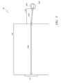
- FIG. 1is a perspective view of an embodiment of a coordinate measuring machine (CMM);
- CCMcoordinate measuring machine
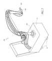
- FIG. 2is a perspective view of another embodiment of a CMM
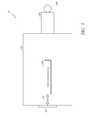
- FIG. 3is a schematic illustration of an embodiment of a probe for the CMM of FIG. 1 or 2 ;
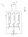
- FIG. 3Ais a schematic illustration of an embodiment of a probe for the CMM of FIG. 1 or 2 ;
- FIG. 4is a schematic illustration of another embodiment of a probe for the CMM of FIG. 1 or 2 ;
- FIG. 5is a schematic illustration of another embodiment of a probe for the CMM of FIG. 1 or 2 .
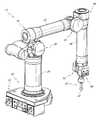
- FIG. 1illustrates one embodiment portable coordinate measuring machine (PCMM) 10 . While the illustrated embodiment is a portable coordinate measuring machine, it should be appreciated that certain embodiments can be applied in the context of a non or semi portable CMM.
- the PCMM 10comprises a base 20 , a plurality of rigid transfer members 24 , 26 , 28 , a coordinate acquisition member 30 and a plurality of articulation members 40 , 42 , 44 , 46 , 48 , 50 connecting the rigid transfer members 24 , 26 , 28 to one another.
- Each articulation memberis configured to impart one or more rotational and/or angular degrees of freedom.
- the PCMM 10can be aligned in various spatial orientations thereby allowing fine positioning of the coordinate acquisition member 30 in three dimensional space.
- the position of the rigid transfer members 24 , 26 , 28 and the coordinate acquisition member 30may be adjusted using manual, robotic, semi-robotic and/or any other adjustment method.
- the PCMM 10through the various articulation members, is provided with seven rotary axes of movement. It will be appreciated, however, that there is no strict limitation to the number of axes of movement that may be used, and fewer or additional axes of movement may be incorporated into the PCMM design.
- the coordinate acquisition member 30comprises a contact sensitive member or contact probe 32 configured to engage the surfaces of a selected object and generate coordinate data on the basis of probe contact.
- the contact probe 32can be a hard probe, which can be substantially rigid and solid. Devices or modules for detecting and/or indicating contact can be disposed outside the hard probe, as discussed further below. As also discussed further below, the probe contact can be indicated by a detected vibration on, near, or within the probe.
- the coordinate acquisition member 30may additionally comprise other methods and devices for detecting position such as a remote scanning and detection component that does not necessarily require direct contact with the selected object to acquire geometry data.
- a laser coordinate detection devicee.g., laser camera
- various coordinate acquisition member methods and devices for detecting position and/or contactincluding: a contact-sensitive probe, a remote-scanning probe, a laser-scanning probe, a probe that uses a strain gauge for contact detection, a probe that uses a pressure sensor for contact detection, a probe that used an infrared beam for positioning, and a probe configured to be electrostatically-responsive may also be combined with a vibration detection probe (as described below) for the purposes of coordinate acquisition.
- one or more of the rigid transfer members 24 , 26 , 28comprise a composite structure that includes an inner portion and an outer exoskeletal portion.
- the inner portion of the rigid transfer members 24 , 26 , 28are interconnected to one another through articulation members that provide the ability to position the coordinate acquisition member 30 in a variety of different orientations in three dimensional space.
- the outer portions surrounding the various inner portions of the rigid transfer members 24 , 26 , 28form an environmental barrier that at least partially encloses segments of the inner portions.
- the inner portionsare configured to “float” inside the corresponding outer portions.
- the position of the probe 32 in space at a given instantcan be calculated by knowing the length of each member and the specific position of each of the articulation members 40 , 42 , 44 , 46 , 48 , 50 .
- Each of the articulation members 40 , 42 , 44 , 46 , 48 , 50can be broken down into a singular rotational degree of motion, each of which is measured using a dedicated rotational transducer.
- Each transduceroutputs a signal (e.g., an electrical signal), which varies according to the movement of the 40 , 42 , 44 , 46 , 48 , 50 in its degree of motion.
- the signalcan be carried through wires or otherwise transmitted to the base 20 . From there, the signal can be processed and/or transferred to a computer for determining and recording the position of the probe 32 in space.
- the transducercan comprise an optical encoder.
- each encodermeasures the rotational position of its axle by coupling is movement to a pair of internal wheels having successive transparent and opaque bands.
- lightcan be shined through the wheels onto optical sensors which feed a pair of electrical outputs.
- the output of the analog encodercan be substantially two sinusoidal signals which are 90 degrees out of phase. Coarse positioning can occur through monitoring the change in polarity of the two signals. Fine positioning can be determined by measuring the actual value of the two signals at the instant in question. In certain embodiments, maximum accuracy can be obtained by measuring the output precisely before it is corrupted by electronic noise.
- the base 20 of the PCMM 10may be situated on a support surface, such as a table, floor, wall or any other stable surface.
- the base 20 Amay be positioned on a mobile unit 14 , allowing the PCMM 10 A to be conveniently moved from one location to another.
- the base 20 Amay be secured to the mobile unit 14 in a fixed manner (e.g. bolted, fastened or otherwise attached at one or more locations).
- the mobile unit 14may be configured with retractable or drop-down wheels 16 that facilitate in moving the PCMM 10 A.
- the wheels 16When properly positioned at the desired location, the wheels 16 may be retracted and rigid support legs (not shown) that can used to secure the PCMM 10 A in a fixed and stable position in preparation for the acquisition of coordinate data. Additional details of this embodiment of the PCMM 10 can be found in U.S. Pat. No. 7,152,456 (issued 26 Dec. 2006) the entirety of which is hereby incorporated by reference herein.
- the various devices which may be used for coordinate acquisitionsuch as the probe 32
- the various devices which may be used for coordinate acquisitionmay be configured to be manually disconnected and reconnected from the PCMM 10 such that a user can change probes without specialized tools.
- a usercan quickly and easily remove one probe and replace it with another probe.
- Such a connectionmay comprise any quick disconnect or manual disconnect device.
- This rapid connection capability of a probecan be particularly advantageous in a PCMM that can be used for a wide variety of measuring techniques (e.g. measurements requiring physical contact of the probe with a surface followed by measurements requiring only optical contact of the probe) in a relatively short period of time. Further details regarding probes and rapid connection capability can be found in U.S.
- the probe 30also comprises buttons 66 , which are configured to be accessible by a user. By pressing one or more of the buttons 66 singly, multiply, or in a preset sequence, the user can input various commands to the PCMM 10 .
- the buttons 66can be used to indicate that one or more coordinate readings are ready to be recorded.
- the buttons 66can be used to indicate that the location being measured is a home position and that other positions should be measured relative to the home position.
- the buttons 66may be used to turn on or off the PCMM 10 .
- the buttons 66can be programmable to meet a user's specific needs.
- buttons 66 on the probe 30can be advantageous in that a user need not access the base 20 or a computer in order to activate various functions of the PCMM 10 while using the probe 32 or more generally the coordinate acquisition member 30 .
- This positioningmay be particularly advantageous in embodiments of PCMM having transfer members 24 , 26 , or 28 that are particularly long, thus placing the base 20 out of reach for a user of the coordinate acquisition member 30 .
- any number of user input buttons(for example having more or fewer than the three illustrated in FIG. 1 ), can be provided, which may be placed in various other positions on the coordinate acquisition member 30 or anywhere on the PCMM 10 .
- Other embodiments of PCMMcan include other user input devices positioned on the PCMM 10 or the coordinate acquisition member 30 , such as switches, rotary dials, or touch pads in place of, or in addition to user input buttons.
- FIGS. 3-5illustrate several embodiments of probes 32 comprising modules or devices configured to provide information relating to detecting contact, as well as other capabilities.
- the term “modules” or “devices”refer to logic embodied by hardware or software (including firmware), or to a combination of both hardware and software, or to a collection of software instructions.
- Software instructionsmay be embedded in firmware, such as an EPROM, and executed by a processor.
- hardware modulesmay include connected logic units, such as gates and flip-flops, and/or may include programmable units, such as programmable gate arrays or processors.
- the modules described hereincan be implemented as software modules, or may be represented in hardware or firmware. Generally, the modules described herein refer to logical modules that may be combined with other modules or divided into sub-modules despite their physical organization or storage.
- FIG. 3schematically illustrates one embodiment of an improved probe 32 .
- the probe 32comprises a probe carriage 100 , a probe mount 101 , a probe neck 105 , and a probe tip 108 .
- the probe carriage 100can be a last tube of the PCMM 10 , and can be configured to house various modules that, for example, sense vibration, obtain real-time data, and/or provide information relating to calibrating the probe with the PCMM, etc.
- the probe mount 101is configured to attach the probe 32 to the PCMM 10 , or other embodiments of PCMMs or CMMs described herein or otherwise known in the art. Similarly, the other probes described herein can also be applied to various PCMMs or CMMs.
- the connection provided by the probe mount 101can be a permanent connection, a reversible connection, a rapid connection, or a similar form of connection.
- the probe neck 105is configured to connect the probe tip 108 with the probe carriage 100 .
- the probe neck 105can be configured to include modules that, for example, obtain the temperature of the probe 32 .
- the probe neck 105can be substantially solid, possibly providing only a narrow bore for the passage of one or more wires.
- the probe tip 108can form an end of the probe 32 and can be configured to engage surfaces of a selected object and/or generate coordinate data on the basis of probe contact as is known in the art.
- the probe tip 108can typically form a circular ball or sphere, but other shapes are possible.
- the probe carriage 100further comprises a vibration detection device 200 .
- the vibration detection device 200is described herein as an accelerometer, other methods of vibration detection known in the art can be used such as various configurations of capacitive touch sensors or MEMS microphones.
- the accelerometer 200can detect vibration using a structure suspended with springs having differential capacitors that provide a signal indicative of the position of the structure, and accordingly the deflection of the springs.
- the accelerometer 200comprises a micro electro-mechanical system (MEMS) that comprises a cantilever beam with a proof mass (or seismic mass) positioned within a gas sealed environment that provides for damping. Under the influence of external acceleration the proof mass deflects from its neutral position.
- MEMSmicro electro-mechanical system
- This deflectioncan be measured in an analog or digital manner.
- the capacitance between a set of fixed beams and a set of beams attached to the proof massis measured.
- piezoresistorscan be integrated into the springs to detect spring deformation.
- most accelerometersoperate in-plane, that is, they are designed to be sensitive only to a direction in the plane of the device. By integrating two devices perpendicularly on a single plate a two-axis accelerometer can be made. By adding an additional out-of-plane device three axes can be measured.
- the accelerometer 200that can be used in light of the disclosure herein.
- the accelerometer 200can connect to the probe mount 101 through a bus line 109 , allowing information from the accelerometer to be transmitted from the probe 32 to the PCMM 10 as well as any other desirable units or sub-components. Accordingly, the accelerometer 200 can be operatively connected to other elements of the PCMM 10 such as the devices for measuring rotational position described above.
- the operative connectioncan be direct, with a signal passing from the accelerometer 200 to the sub-components unaltered.
- the operative connectioncan be indirect, perhaps passing through a processor (described below) that may alter the signal or generate a new signal to pass to the sub-components at least partially dependent on a signal from the accelerometer 200 .
- the operative connectioncan be indirect, passing through a series of intermediate components.
- the accelerometer 200can advantageously detect vibrations on or from the probe tip 108 .
- the accelerometercan be rigidly attached to the probe tip 108 , either directly or indirectly. Such rigid attachment can minimize damping of vibrations propagating from the probe tip 108 to the accelerometer 200 .
- the accelerometer 200can be connected in such a manner that minimizes continuing vibrations after an initial acceleration of the probe tip 108 .
- the accelerometer 200can be directly supported, and not cantilevered or suspended.
- the accelerometer 200can be configured to measure vibrations in a variety of directions, including three translational and three rotational directions. However, in some embodiments fewer vibrational directions can be detected. For example, as rotational vibrations may be less significant in operation, in some embodiments only the three translational vibrations can be measured. Further, in some embodiments a simplified accelerometer 200 may be desired, in which case only translational vibrations parallel to the probe neck 105 can be measured. More generally, the vibrations measured can vary depending on the intended use of the PCMM 10 .
- the accelerometer 200can indicate this activity to the PCMM 10 , and thus trigger a measurement of the position of the probe tip 108 .
- the rotational degree of the articulation members 40 , 42 , 44 , 46 , 48 , 50can be recorded and/or taken.
- the accelerometercan provide this indication directly to e.g. encoders associated with the articulation members.
- the indicationcan be provided indirectly, e.g. via a processor on the probe 32 (discussed further below) or some other device on the PCMM 10 .
- the encoderscan be continuously outputting a rotational position to a separate processor, which is also operatively connected to the accelerometer 200 .
- the accelerometercan trigger the recording of desired data such as rotational position.
- the accelerometer 200can indicate contact only under particular circumstances.
- the probe 32can be configured to indicate contact when the accelerometer 200 measures an acceleration of at least a particular threshold amplitude.
- the probe 32can indicate contact when the acceleration changes by a particular amount in a particular amount of time (e.g. a threshold jerk).
- a threshold duration of the acceleration or jerkcan be required for the probe 32 to indicate contact. For example, in some embodiments only accelerations or jerks with a sufficiently long duration indicate contact (minimum duration).
- the acceleration or jerkmust end (or decline) after a certain duration of time (maximum duration). Even further, in some embodiments a second contact can only be indicated after a certain cooldown time has passed since the last indicated contact (cooldown duration).
- the particular requirements for indication of contactcan be varied depending on the intended use of the PCMM 10 . For example, if the PCMM 10 is automated then the probe 32 can be configured to take into account the actual or possible movement of the PCMM 10 , and accordingly ignore accelerations and vibrations caused solely by this movement. If the PCMM 10 is manually operated, it can be similarly configured in light of the different expected movements. For example, the probe 32 can be configured to ignore vibrations caused by the pressing of a button 66 .
- the pressing of one of said buttons 66can also signal the probe 32 to begin monitoring for vibrations from contact.
- the probe 32can be configured to ignore vibrations caused during periods of substantially continued high vibrations that can reduce accuracy (as the PCMM can be calibrated under quasi-static conditions).
- the criteria for indicating contactcan be configured to check for a new vibration, distinct from other ongoing vibrations.
- two acceleration measurements taken close together in timecan be compared. If the magnitude of the difference in the two acceleration measurements is above a specified threshold, then the probe 32 can indicate contact.
- the difference in accelerationscan be a difference in measured acceleration vectors, and the magnitude of the difference can be the norm of the difference.
- the differences in accelerationcan be analyzed differently, such as by summing the absolute values of the change in acceleration in each component direction.
- the threshold level and the time interval between measurementscan vary with the PCMM 10 , the probe 32 , and their intended use.
- the comparisoncan be implemented in hardware where, for example, one acceleration measurement is delayed and the two accelerations are compared by a comparator circuit.
- a probe 32 that is triggered by such vibrationscan, in some embodiments, have no moving parts. In other embodiments, the probe 32 can have fewer moving parts.
- the probe 32can optionally lack a vibrator or some other device that purposefully initiates vibrations in the probe 32 or PCMM 10 (independent of contact vibrations). The reduction in moving parts can make the probe 32 less expensive to produce and more reliable over the lifetime of the probe 32 .
- the probe 32can optionally operate as a standard hard contact probe when operated in a different mode, possibly controlled by modules or devices on the probe 32 or elsewhere on the CMM 10 , as further described below.
- FIG. 3Adepicts another embodiment of a probe 32 , similar to that depicted in FIG. 3 and with the optional variations described relative thereto, except where otherwise stated.
- the carriage 100can also include several modules configured, for example, to provide data uniquely identifying the probe 32 , facilitate calibration of the probe with the PCMM 10 , etc.
- the probe carriage 100comprises a processor 102 , a solid-state memory device 104 , a temperature sensor 106 , and an accelerometer 200 .
- the solid-state memory device 104 , the temperature sensor 106 , and the accelerometer 200are connected to the processor 102 using bus lines 103 , 111 , 110 respectively.
- the processor 102 , memory 104 , temperature sensor 106 , and accelerometer 200may all be integrated in one chip. In other embodiments, they may be separate components mounted on a circuit board or electronically coupled, such as with a wired connection. In other embodiments, only one, two, or three of the components may be present and others not required.
- the bus line 109can connect the processor 102 to the probe mount 101 such that any information obtained by the processor 102 from the solid-state memory device 104 , the temperature sensor 106 , and the accelerometer 200 is transmitted from the probe 32 to the PCMM 10 to which the probe 32 is attached.
- the PCMM 10can use the transmitted information to calibrate the probe 32 with the PCMM 10 .
- the PCMM 10can retransmit the obtained information to a general purpose computer (not shown) configured to calibrate the probe 32 with the PCMM 10 .
- the PCMM 10can use the information the PCMM obtains from the processor 102 to retrieve calibration or nominal data related to the probe 32 that is stored in a different media such as a memory key, hard disk, or a computer, as will be further described below.
- the PCMM 10uses the information to indicate contact with an object to be measured and accordingly measures the position of the probe tip 108 at that time.
- the processor 102in one embodiment is a general purpose central processing unit (CPU) configured to control operations of various modules of the probe 32 , including the solid-state memory device 104 , the temperature sensor 106 , and accelerometer 200 .
- processorscould include, but are not limited to, separate or individual processing cores, separate or distributed processing logic, general purpose processors, special purpose processors, application specific integrated circuits (ASICs) with processing functionality, memory controllers, system controllers, etc.
- the processor 102can be connected to the solid-state memory device 104 through bus line 103 , the temperature sensor 106 through the bus line 111 , and the accelerometer 200 through bus line 110 .
- the processor 102is configured to control the operation of the solid-state memory device 104 , the temperature sensor 106 , and the accelerometer 200 using connections 103 , 111 and 110 .
- the processor 102controls the solid-state memory device 104 , for example, by sending instruction to read a particular address in the solid-state memory device 104 and receiving a data signal from the solid-state memory device 104 corresponding to the address sent by the processor 102 .
- the processor 102transmits the data it receives from the solid-state memory device 104 to the PCMM 10 using the bus line 109 .
- the processor 102obtains a temperature reading from the temperature sensor 106 using the bus line 103 and transmits the temperature reading to the PCMM 10 using the bus line 109 .
- data transfer to and from the processor 102can be made wirelessly using a wireless data transmission protocol.
- the solid-state memory device 104can be capable of accepting data, storing the data, and subsequently providing the data.
- the solid-state memory device 104 as illustrated in FIG. 3Adepicts a non-volatile electrically erasable programmable read-only memory (EEPROM) device.
- the processor 102 or another memory controllercan selectively write or erase any part of the EEPROM without the need to write or erase the entire EEPROM.
- EEPROMis preferably used in connection with the probe 32 in the various embodiments contained herein, the probe 32 can be configured to comprise any suitable non-volatile electronic data storage device, including, but not limited to, tape, hard disk, optical disk, Flash memory, programmable read-only memory (PROM), erasable PROM (EPROM), etc.
- the sold-state memory device 104is an EEPROM device comprising a 48-bit laser etched serial number.
- the processor 102can be configured to control the operation of the solid-state memory device 104 by sending control signals through the control lines 103 , such as, for example, instructions for the solid-state memory device 104 to write data transmitted through a data bus (not shown) to a memory cell address sent through the address bus (not shown).
- the processor 102controls the operation of the solid-state memory device 104 using separate system and memory controllers (not shown).
- the solid-state memory device 104in one embodiment can be configured to include a unique serial or product number, machine readable data that uniquely identifies the particular probe 32 on which the solid-state memory device 104 is located.
- the unique serial numberallows individual serialization of all of the improved probes to advantageously allow subsequent identification of each one of the probes 32 .
- the unique serial numbercan even identify individual probes 32 that belong to the same type or category.
- the solid-state memory device 104can include information identifying it as including a vibration detection device 200 .
- a solid-state memory device 104comprising a machine readable unique serial number identifying the probe 32 has several advantages. As previously mentioned, if the probe 32 is mounted to the PCMM 10 for the first time, or if a new probe 32 is used for the first time, the probe 32 must be calibrated with the PCMM 10 . Each probe 32 has nominal data relating to characteristics of the probe 32 , such as, for example, length, category, type, offsets, width, thickness, etc. that is usually contained in different media such as disks, memory keys, etc. This nominal data is used as a starting point to calibrate the probe 32 with the PCMM 10 . In some embodiments, the nominal data is stored in a computer that is connected to the PCMM 10 .
- the nominal datais stored in a storage area located on the PCMM 10 .
- the nominal data for the probe 32is stored in a different storage media along with the machine readable unique serial number for that particular probe 32 .
- the PCMM 10can obtain the nominal data for the probe 32 by first reading the machine readable unique serial number from the probe 32 and obtaining the nominal data located on different media which contains the same unique serial number.
- the machine readable unique serial number identifying the probe 32can be used to better match the probe 32 with the corresponding nominal data stored on a different media than conventional systems, some of which do not distinguish probes 32 of the same type or category.
- the machine readable serial number uniquely identifying the probe 32can be used to match calibration data with the probe 32 .
- the resultcan be data that provides translation from the end of the PCMM 10 to the tip of the probe 32 .
- the calibration datacan indicate vibration characteristics between the PCMM 10 and the probe 32 , such as the propensity for vibrations to propagate between the two, vibrations created by the contactless movement of the PCMM 10 , and other characteristics. The calibration data can therefore be unique to the particular PCMM 10 and probe 32 combination.
- the calibration datais also typically stored in media different from the coordinate acquisition device 30 , such as, for example, a memory key, hard disk on a computer, or storage area located on the PCMM 10 , etc.
- the PCMM 10stores the calibration data for a probe 32 on the different media along with the machine readable serial number of the particular probe 32 .
- the PCMM 10can obtain the calibration data that is specific to the probe 32 from the different media by first reading the machine readable unique serial number from the probe 32 and obtaining the calibration data that contains the same serial number.
- the machine readable serial numberis stored in the solid-state memory device 104 in the previously disclosed embodiments, the machine readable serial number in other embodiments can be located elsewhere on the probe 32 . In some embodiments, the serial number is located on another module located in the probe carriage 100 , such as, for example, the processor 102 . In other embodiments, the machine readable serial number can be provided by an integrated package of software and/or hardware similar to systems used in warehouse operations, such as, for example, bar codes and RFID tags.
- the solid-state memory device 104can be configured to store nominal data.
- the processor 102stores the nominal data relating to physical characteristics of the probe 32 into the solid-state memory device 104 , for example, using the control line 103 .
- the nominal datacan be written in the solid-state device 104 during the manufacture stage of the probe 32 .
- nominal datais written into the solid-state memory device 104 after the probe 32 is assembled, for example, using a general purpose computer configured to write nominal data into the solid-state memory device 104 .
- an RFID tag on the probe 32can store the machine readable serial number and/or nominal data.
- the PCMM 10can wirelessly retrieve the serial number and/or nominal data from the RFID tag. In other embodiments, communication between the CMM and probe can occur through other wireless protocols, such as WiFi, Bluetooth, or RF. In still other embodiments, the PCMM 10 first reads the machine readable unique serial number from the solid-state device 104 , then obtains the nominal data based on the machine readable unique serial number, for example from a different media such as a memory key or another computer, and stores the nominal data into the solid-state device 104 such that the probe 32 will retain nominal data for use in subsequent calibrations.
- a solid-state memory device 104 configured to store nominal dataeliminates the need to maintain a separate media to store nominal data, thereby reducing the difficulty of managing large number of probes and their associated nominal data.
- the probe 32can use the temperature sensor 106 to measure the temperature of the probe 32 and provide the temperature information to the PCMM 10 .
- the position of the probe 32 in space at a given instantcan be calculated if the length of each transfer member 24 , 26 , and 28 and the length of the probe 32 are known.
- the length and other physical parameters of the probe 32can be obtained by the PCMM 10 during calibration, for example, by reading nominal data from the solid-state memory device 104 .
- the length of the probe 32may change, for example, by expanding in response to an increase in temperature.
- the transfer members 24 , 26 , and 28 of the PCMM 10 and the probe 32are composed of different material with different heating coefficients and, therefore, expand and/or contract in response to temperature at a different rates.
- the transfer members 24 , 26 , and 28 and the probe 32are composed of the same material but expand and/or contract at a different rate because the temperature of the probe 32 can be different from temperature of the PCMM 10 , for example, due to the heat generated within the PCMM 10 .
- the PCMM 10can use the temperature sensor 106 to compensate for the expansion or contraction of the probe 32 due to changes in temperature.
- the solid-state memory device 104contains nominal data related to the temperature characteristics of the probe 32 , such as, for example, heating coefficient information, length at a certain default temperature, etc.
- the PCMM 10can obtain the temperature of the probe 32 from the temperature sensor 106 , obtain the coefficient of thermal expansion of the probe 32 from the solid-state memory device 104 , and calculate any changes in the physical characteristics of the probe 32 using the obtained temperature and the coefficient of thermal expansion of the probe 32 .
- the temperature of the probe 32 and the coefficient of thermal expansion of the probe 32are transmitted, for example by the processor 102 , to a general purpose computer attached to the PCMM 10 in order to calculate the changes in physical characteristics of the probe 32 .
- the PCMM 10 or the general purpose computerobtain the coefficient of thermal expansion of the probe 32 from a different media, such as, for example, a memory key, a disk, a database, etc.
- the PCMM 10 and/or general purpose computeruse the unique machine readable serial number of the probe 32 to obtain the appropriate coefficient of thermal expansion of the probe 32 from the different media.
- Compensating for the expansions or contractions of the probe 32 due to changes in temperature using the temperature sensor 106 in the above-described mannereliminates the need for the PCMM 10 to recalibrate the probe 32 in response to temperature effects. Further, other changes to the probe 32 can be computed from changes in temperature, such as the behavior of sensors such as the vibration detection device 200 .
- the processor 102can be configured to determine whether a given signal from the vibration detection device 200 should be considered to indicate contact.
- the various possible rules described abovecan be inputted into the processor 102 as software or hardware.
- the processor 102can further calibrate the rules for contact detection by continuously examining the output of the vibration detection device 200 during movement of the PCMM 10 absent contact, for example during a vibration calibration procedure.
- the vibration calibration procedurecan involve movement of the PCMM 10 in a manner similar to that during normal operation, absent actual contact with any object. This can be used to appropriately set the various thresholds and other possible contact detection parameters such as those described herein.
- the probe 32 of FIG. 2comprises the processor 102 , solid-state memory device 104 , temperature sensor 106 and accelerometer 200 as separate modules located on the probe carriage 100 , other configurations are possible. For example, some or all of the modules the processor 102 , solid-state memory device 104 , temperature sensor 106 and accelerometer 200 may be located on a different area of the probe 32 or the PCMM 10 (as further described below). Further still, the probe 32 may comprise modules that combine the functions of one or more of the processor 102 , solid-state memory device 104 , temperature sensor 106 and accelerometer 200 .
- additional coordinate sensorscan be included on the coordinate acquisition member 30 , and can also be associated with the above described devices and modules.
- additional sensorscan be included to monitor the state of various portions of the PCMM 10 . Further devices and modules, and the arrangement and use thereof, is described in U.S. patent application Ser. No. 12/057,918, filed Mar. 28, 2008, which is incorporated herein by reference in its entirety as stated above.
- FIG. 4depicts another embodiment of an improved probe 32 .
- the vibration detection device 200can be located within the probe tip 108 . As the vibration detection device 200 is further distanced from the probe mount 101 , they can connect via two bus lines in series 109 A, 109 B.
- the embodiment depicted in FIG. 4can have similar features to the embodiments depicted in FIGS. 3 and 3A , and can operate in a similar manner and with the optional variations described relative thereto, except where otherwise stated.
- the vibration detection device 200can be separated from the other modules and devices where, as depicted, it is located within the probe tip 108 . However, in other embodiments each of the devices and modules can be held within the probe tip.
- FIG. 5depicts another embodiment of a probe 32 , again similar to the embodiments depicted in FIGS. 3 and 3A and with the optional variations described relative thereto, except where otherwise stated.
- the vibration detection device 200can be located within the probe mount 101 . Accordingly, the vibration detection device 200 can be generally separate from the probe 32 , as in some embodiments the probe 32 can detach from the probe mount 101 and the PCMM 10 . Accordingly, the PCMM 10 can detect vibrations even when using standard prior art probes that lack a vibration detection device (e.g., a hard probe). Similarly, where the vibration detection device 200 is on the probe 32 , the probe 32 can be used with prior art PCMM arms to detect vibration.
- a vibration detection devicee.g., a hard probe
- moving the vibration detection device 200 further from the tip 108can advantageously reduce error and delay in the transmission of the signal therefrom, as the signal does not travel as far.
- the greater distance between the vibration detection device 200 and the probe tip 108can increase the error between the measured vibrations and the actual vibrations at the tip.
Landscapes
- Physics & Mathematics (AREA)
- General Physics & Mathematics (AREA)
- Length Measuring Devices With Unspecified Measuring Means (AREA)
- A Measuring Device Byusing Mechanical Method (AREA)
- Measurement Of Mechanical Vibrations Or Ultrasonic Waves (AREA)
Abstract
Description
Claims (28)
Priority Applications (2)
| Application Number | Priority Date | Filing Date | Title |
|---|---|---|---|
| US12/825,185US8104189B2 (en) | 2009-06-30 | 2010-06-28 | Coordinate measurement machine with vibration detection |
| US13/331,974US8220173B2 (en) | 2009-06-30 | 2011-12-20 | Coordinate measurement machine with vibration detection |
Applications Claiming Priority (2)
| Application Number | Priority Date | Filing Date | Title |
|---|---|---|---|
| US22197309P | 2009-06-30 | 2009-06-30 | |
| US12/825,185US8104189B2 (en) | 2009-06-30 | 2010-06-28 | Coordinate measurement machine with vibration detection |
Related Child Applications (1)
| Application Number | Title | Priority Date | Filing Date |
|---|---|---|---|
| US13/331,974ContinuationUS8220173B2 (en) | 2009-06-30 | 2011-12-20 | Coordinate measurement machine with vibration detection |
Publications (2)
| Publication Number | Publication Date |
|---|---|
| US20100325907A1 US20100325907A1 (en) | 2010-12-30 |
| US8104189B2true US8104189B2 (en) | 2012-01-31 |
Family
ID=43379172
Family Applications (2)
| Application Number | Title | Priority Date | Filing Date |
|---|---|---|---|
| US12/825,185Expired - Fee RelatedUS8104189B2 (en) | 2009-06-30 | 2010-06-28 | Coordinate measurement machine with vibration detection |
| US13/331,974Expired - Fee RelatedUS8220173B2 (en) | 2009-06-30 | 2011-12-20 | Coordinate measurement machine with vibration detection |
Family Applications After (1)
| Application Number | Title | Priority Date | Filing Date |
|---|---|---|---|
| US13/331,974Expired - Fee RelatedUS8220173B2 (en) | 2009-06-30 | 2011-12-20 | Coordinate measurement machine with vibration detection |
Country Status (6)
| Country | Link |
|---|---|
| US (2) | US8104189B2 (en) |
| EP (2) | EP3620762A1 (en) |
| CN (1) | CN102472662B (en) |
| AU (1) | AU2010273749B2 (en) |
| CA (1) | CA2766906C (en) |
| WO (1) | WO2011008503A2 (en) |
Cited By (24)
| Publication number | Priority date | Publication date | Assignee | Title |
|---|---|---|---|---|
| US20120246953A1 (en)* | 2009-10-06 | 2012-10-04 | Thomas Engel | Coordinate measuring device having positional change sensors |
| US8402669B2 (en) | 2009-11-06 | 2013-03-26 | Hexagon Metrology Ab | Articulated arm |
| US8429828B2 (en) | 2010-08-31 | 2013-04-30 | Hexagon Metrology, Inc. | Mounting apparatus for articulated arm laser scanner |
| US8438747B2 (en) | 2008-10-16 | 2013-05-14 | Hexagon Metrology, Inc. | Articulating measuring arm with laser scanner |
| US8453338B2 (en) | 2008-03-28 | 2013-06-04 | Hexagon Metrology, Inc. | Coordinate measuring machine with rotatable grip |
| USD687322S1 (en) | 2010-03-29 | 2013-08-06 | Hexagon Metrology Ab | Coordinate acquistion member of a portable coordinate measurement machine |
| US8763267B2 (en) | 2012-01-20 | 2014-07-01 | Hexagon Technology Center Gmbh | Locking counterbalance for a CMM |
| US8792709B2 (en) | 2004-01-14 | 2014-07-29 | Hexagon Metrology, Inc. | Transprojection of geometry data |
| US20140211828A1 (en)* | 2013-01-28 | 2014-07-31 | Blum-Novotest Gmbh | Temperature-compensated measuring probe to be received in a workpiece-processing machine, and temperature compensation of a measuring probe |
| US9069355B2 (en) | 2012-06-08 | 2015-06-30 | Hexagon Technology Center Gmbh | System and method for a wireless feature pack |
| US9163921B2 (en) | 2013-12-18 | 2015-10-20 | Hexagon Metrology, Inc. | Ultra-portable articulated arm coordinate measurement machine |
| US9250214B2 (en) | 2013-03-12 | 2016-02-02 | Hexagon Metrology, Inc. | CMM with flaw detection system |
| US9594250B2 (en) | 2013-12-18 | 2017-03-14 | Hexagon Metrology, Inc. | Ultra-portable coordinate measurement machine |
| US9739591B2 (en) | 2014-05-14 | 2017-08-22 | Faro Technologies, Inc. | Metrology device and method of initiating communication |
| US9746308B2 (en) | 2014-05-14 | 2017-08-29 | Faro Technologies, Inc. | Metrology device and method of performing an inspection |
| US9759540B2 (en) | 2014-06-11 | 2017-09-12 | Hexagon Metrology, Inc. | Articulating CMM probe |
| US9803969B2 (en) | 2014-05-14 | 2017-10-31 | Faro Technologies, Inc. | Metrology device and method of communicating with portable devices |
| US9829305B2 (en) | 2014-05-14 | 2017-11-28 | Faro Technologies, Inc. | Metrology device and method of changing operating system |
| US9903701B2 (en) | 2014-05-14 | 2018-02-27 | Faro Technologies, Inc. | Articulated arm coordinate measurement machine having a rotary switch |
| US9921046B2 (en) | 2014-05-14 | 2018-03-20 | Faro Technologies, Inc. | Metrology device and method of servicing |
| USD875573S1 (en) | 2018-09-26 | 2020-02-18 | Hexagon Metrology, Inc. | Scanning device |
| US10869175B2 (en) | 2014-11-04 | 2020-12-15 | Nathan Schumacher | System and method for generating a three-dimensional model using flowable probes |
| US11022434B2 (en) | 2017-11-13 | 2021-06-01 | Hexagon Metrology, Inc. | Thermal management of an optical scanning device |
| US11311871B2 (en)* | 2019-02-22 | 2022-04-26 | Beckman Coulter, Inc. | Detection and targeted remediation of mechanical device alignment errors |
Families Citing this family (53)
| Publication number | Priority date | Publication date | Assignee | Title |
|---|---|---|---|---|
| EP2092269B1 (en) | 2006-11-20 | 2019-05-01 | Hexagon Technology Center GmbH | Coordinate measurement machine with improved joint |
| US8122610B2 (en)* | 2008-03-28 | 2012-02-28 | Hexagon Metrology, Inc. | Systems and methods for improved coordination acquisition member comprising calibration information |
| US9551575B2 (en) | 2009-03-25 | 2017-01-24 | Faro Technologies, Inc. | Laser scanner having a multi-color light source and real-time color receiver |
| DE102009015920B4 (en) | 2009-03-25 | 2014-11-20 | Faro Technologies, Inc. | Device for optically scanning and measuring an environment |
| US8104189B2 (en) | 2009-06-30 | 2012-01-31 | Hexagon Metrology Ab | Coordinate measurement machine with vibration detection |
| US9113023B2 (en) | 2009-11-20 | 2015-08-18 | Faro Technologies, Inc. | Three-dimensional scanner with spectroscopic energy detector |
| US9529083B2 (en) | 2009-11-20 | 2016-12-27 | Faro Technologies, Inc. | Three-dimensional scanner with enhanced spectroscopic energy detector |
| DE102009057101A1 (en) | 2009-11-20 | 2011-05-26 | Faro Technologies, Inc., Lake Mary | Device for optically scanning and measuring an environment |
| US9210288B2 (en) | 2009-11-20 | 2015-12-08 | Faro Technologies, Inc. | Three-dimensional scanner with dichroic beam splitters to capture a variety of signals |
| US20110213247A1 (en)* | 2010-01-08 | 2011-09-01 | Hexagon Metrology, Inc. | Articulated arm with imaging device |
| US8630314B2 (en) | 2010-01-11 | 2014-01-14 | Faro Technologies, Inc. | Method and apparatus for synchronizing measurements taken by multiple metrology devices |
| US9628775B2 (en) | 2010-01-20 | 2017-04-18 | Faro Technologies, Inc. | Articulated arm coordinate measurement machine having a 2D camera and method of obtaining 3D representations |
| US9163922B2 (en) | 2010-01-20 | 2015-10-20 | Faro Technologies, Inc. | Coordinate measurement machine with distance meter and camera to determine dimensions within camera images |
| US8875409B2 (en) | 2010-01-20 | 2014-11-04 | Faro Technologies, Inc. | Coordinate measurement machines with removable accessories |
| US8615893B2 (en) | 2010-01-20 | 2013-12-31 | Faro Technologies, Inc. | Portable articulated arm coordinate measuring machine having integrated software controls |
| WO2011090895A1 (en) | 2010-01-20 | 2011-07-28 | Faro Technologies, Inc. | Portable articulated arm coordinate measuring machine with multi-bus arm technology |
| US8832954B2 (en) | 2010-01-20 | 2014-09-16 | Faro Technologies, Inc. | Coordinate measurement machines with removable accessories |
| US9879976B2 (en) | 2010-01-20 | 2018-01-30 | Faro Technologies, Inc. | Articulated arm coordinate measurement machine that uses a 2D camera to determine 3D coordinates of smoothly continuous edge features |
| US8677643B2 (en) | 2010-01-20 | 2014-03-25 | Faro Technologies, Inc. | Coordinate measurement machines with removable accessories |
| US9607239B2 (en) | 2010-01-20 | 2017-03-28 | Faro Technologies, Inc. | Articulated arm coordinate measurement machine having a 2D camera and method of obtaining 3D representations |
| US8898919B2 (en) | 2010-01-20 | 2014-12-02 | Faro Technologies, Inc. | Coordinate measurement machine with distance meter used to establish frame of reference |
| US8942940B2 (en)* | 2010-01-20 | 2015-01-27 | Faro Technologies, Inc. | Portable articulated arm coordinate measuring machine and integrated electronic data processing system |
| US8284407B2 (en) | 2010-01-20 | 2012-10-09 | Faro Technologies, Inc. | Coordinate measuring machine having an illuminated probe end and method of operation |
| DE102010020925B4 (en) | 2010-05-10 | 2014-02-27 | Faro Technologies, Inc. | Method for optically scanning and measuring an environment |
| US9021344B2 (en)* | 2010-08-31 | 2015-04-28 | New River Kinematics, Inc. | Off-line graphical user interface system and method for three-dimensional measurement |
| GB2501390B (en) | 2010-09-08 | 2014-08-06 | Faro Tech Inc | A laser scanner or laser tracker having a projector |
| USD662427S1 (en) | 2010-11-16 | 2012-06-26 | Faro Technologies, Inc. | Measurement device |
| USD659034S1 (en) | 2010-11-16 | 2012-05-08 | Faro Technologies, Inc. | Display for a measurement device |
| USD659032S1 (en)* | 2010-11-16 | 2012-05-08 | Faro Technologies, Inc. | Laser measurement device |
| US9168654B2 (en) | 2010-11-16 | 2015-10-27 | Faro Technologies, Inc. | Coordinate measuring machines with dual layer arm |
| USD659033S1 (en)* | 2010-11-16 | 2012-05-08 | Faro Technologies, Inc. | Handle for a measurement device |
| USD676309S1 (en) | 2010-11-16 | 2013-02-19 | Faro Technologies, Inc. | Base for a device |
| DE102012100609A1 (en) | 2012-01-25 | 2013-07-25 | Faro Technologies, Inc. | Device for optically scanning and measuring an environment |
| EP2629048B1 (en)* | 2012-02-20 | 2018-10-24 | Tesa Sa | Touch probe |
| JP2015513669A (en)* | 2012-02-21 | 2015-05-14 | ファロ テクノロジーズ インコーポレーテッド | Portable articulated arm coordinate measuring machine with integrated software control |
| EP2677270B1 (en)* | 2012-06-22 | 2015-01-28 | Hexagon Technology Center GmbH | Articulated Arm CMM |
| US8997362B2 (en) | 2012-07-17 | 2015-04-07 | Faro Technologies, Inc. | Portable articulated arm coordinate measuring machine with optical communications bus |
| US10067231B2 (en) | 2012-10-05 | 2018-09-04 | Faro Technologies, Inc. | Registration calculation of three-dimensional scanner data performed between scans based on measurements by two-dimensional scanner |
| US9513107B2 (en) | 2012-10-05 | 2016-12-06 | Faro Technologies, Inc. | Registration calculation between three-dimensional (3D) scans based on two-dimensional (2D) scan data from a 3D scanner |
| DE102012109481A1 (en) | 2012-10-05 | 2014-04-10 | Faro Technologies, Inc. | Device for optically scanning and measuring an environment |
| CN104359436A (en)* | 2014-11-13 | 2015-02-18 | 郑大腾 | Articulated-arm three-coordinate measuring machine, multi-measuring model system and workpiece measuring method |
| MX348535B (en)* | 2014-11-14 | 2017-05-23 | Kaplun Mucharrafille Margarita | Positioning appliance for measurement and analysis. |
| US10006751B2 (en)* | 2015-04-28 | 2018-06-26 | Metrologyworks, Inc. | Smart metrology stand |
| CN105157647B (en)* | 2015-08-31 | 2017-09-12 | 中国航空工业集团公司北京航空精密机械研究所 | Mix eccentrically arranged type joint arm measuring machine |
| DE102015122844A1 (en) | 2015-12-27 | 2017-06-29 | Faro Technologies, Inc. | 3D measuring device with battery pack |
| TWI664130B (en)* | 2016-01-29 | 2019-07-01 | 旺矽科技股份有限公司 | Wafer cassette |
| US10267614B2 (en)* | 2017-04-13 | 2019-04-23 | Sa08700334 | Ultra-light and ultra-accurate portable coordinate measurement machine |
| US11879958B2 (en)* | 2018-06-06 | 2024-01-23 | Honeywell International Inc. | System and method for using an industrial manipulator for atmospheric characterization lidar optics positioning |
| JP7162989B2 (en)* | 2019-02-04 | 2022-10-31 | 株式会社ミツトヨ | One-dimensional measuring machine and program |
| CN110440903A (en)* | 2019-09-03 | 2019-11-12 | 皖西学院 | A kind of lathe viberation detector |
| CN112729521B (en)* | 2020-12-29 | 2023-04-07 | 苏州高瑞工业产品设计有限公司 | Vibration testing mechanism for portable dust collector |
| CN115468646A (en)* | 2022-09-14 | 2022-12-13 | 深圳北芯医疗科技有限公司 | Shockwave sound pressure measuring method, device, system and computer readable storage medium |
| GB2632405A (en)* | 2023-07-31 | 2025-02-12 | Renishaw Plc | Coordinate positioning machine |
Citations (93)
| Publication number | Priority date | Publication date | Assignee | Title |
|---|---|---|---|---|
| US4333238A (en) | 1979-03-30 | 1982-06-08 | Mcmurtry David R | Coordinate measuring machine |
| US4588339A (en) | 1983-07-23 | 1986-05-13 | Otto Bilz, Werkzeugfabrik | Tool holder for a cutting machine provided with numerical control |
| US4782598A (en) | 1985-09-19 | 1988-11-08 | Digital Electronic Automation, Inc. | Active error compensation in a coordinate measuring machine |
| US4972090A (en) | 1989-08-03 | 1990-11-20 | Eaton Homer L | Method and apparatus for measuring and inspecting articles of manufacture for configuration |
| US5084981A (en) | 1989-04-14 | 1992-02-04 | Renishaw Plc | Probe head |
| US5088337A (en) | 1989-04-14 | 1992-02-18 | Renishaw Plc | Probe head |
| US5148377A (en) | 1986-12-10 | 1992-09-15 | Mcdonald Gregory J | Coordinate measuring system |
| EP0522610A1 (en) | 1991-06-26 | 1993-01-13 | Sulzer - Escher Wyss AG | Method and apparatus for surface-contour determination of rotor blades in hydraulic machines |
| US5187874A (en) | 1989-04-28 | 1993-02-23 | Mitutoyo Corporation | Coordinate measuring machine with protected origin point blocks |
| US5189797A (en) | 1991-03-12 | 1993-03-02 | Romer | Apparatus for measuring the shape or position of an object |
| GB2274526A (en) | 1993-01-21 | 1994-07-27 | Motorola Inc | Verifying geometry of a part |
| US5396712A (en) | 1992-11-12 | 1995-03-14 | Carl Zeiss Stiftung | Coordinate measuring device |
| US5408754A (en) | 1993-02-23 | 1995-04-25 | Faro Technologies, Inc. | Method and apparatus for measuring sleeping positions |
| US5412880A (en) | 1993-02-23 | 1995-05-09 | Faro Technologies Inc. | Method of constructing a 3-dimensional map of a measurable quantity using three dimensional coordinate measuring apparatus |
| DE4345091A1 (en) | 1993-12-31 | 1995-07-06 | Perthen Feinpruef Gmbh | Measurement scanning unit with multi-dimensional scanning system |
| US5505003A (en) | 1993-10-08 | 1996-04-09 | M&M Precision Systems Corporation | Generative measuring system |
| US5510977A (en) | 1994-08-02 | 1996-04-23 | Faro Technologies Inc. | Method and apparatus for measuring features of a part or item |
| US5521847A (en) | 1994-07-01 | 1996-05-28 | General Electric Company | System and method for determining airfoil characteristics from coordinate measuring machine probe center data |
| US5526576A (en) | 1993-09-13 | 1996-06-18 | Carl-Zeiss-Stiftung, Heidenheim (Brenz) | Coordinate measurement machine having a probe head and an electronic system for processing probe signals |
| US5528505A (en) | 1993-09-20 | 1996-06-18 | Romer | Position-marking method for a machine that measures in three dimensions, and apparatus for implementing the method |
| US5579246A (en) | 1993-12-11 | 1996-11-26 | Carl-Zeiss-Stiftung | Method and device for the correction of measurement errors due to vibrations in coordinate measuring devices |
| US5611147A (en) | 1993-02-23 | 1997-03-18 | Faro Technologies, Inc. | Three dimensional coordinate measuring apparatus |
| US5615489A (en) | 1992-09-25 | 1997-04-01 | Carl-Zeiss-Stiftung | Method of making coordinate measurements on workpieces |
| FR2740546A1 (en) | 1995-10-25 | 1997-04-30 | Romer Srl | 3D measuring device for geometry of damaged car |
| US5757499A (en) | 1994-06-17 | 1998-05-26 | Eaton; Homer | Method of locating the spatial position of a frame of reference and apparatus for implementing the method |
| US5768792A (en) | 1996-02-09 | 1998-06-23 | Faro Technologies Inc. | Method and apparatus for measuring and tube fitting |
| US5778549A (en) | 1995-09-19 | 1998-07-14 | Deutsche Forschungsanstalt Fur Luft-Und Raumfahrt E.V. | Correcting measurement errors |
| US5822450A (en) | 1994-08-31 | 1998-10-13 | Kabushiki Kaisha Toshiba | Method for monitoring equipment state by distribution measurement data, and equipment monitoring apparatus |
| US5829148A (en) | 1996-04-23 | 1998-11-03 | Eaton; Homer L. | Spatial measuring device |
| US5978748A (en) | 1998-07-07 | 1999-11-02 | Faro Technologies, Inc. | Host independent articulated arm |
| US5991704A (en) | 1998-03-26 | 1999-11-23 | Chrysler Corporation | Flexible support with indicator device |
| US6044569A (en) | 1997-02-10 | 2000-04-04 | Mitutoyo Corporation | Measuring method and measuring instrument |
| US6134506A (en) | 1995-08-07 | 2000-10-17 | Microscribe Llc | Method and apparatus for tracking the position and orientation of a stylus and for digitizing a 3-D object |
| US6161079A (en) | 1997-08-18 | 2000-12-12 | Giddings & Lewis, Llc | Method and apparatus for determining tolerance and nominal measurement values for a coordinate measuring machine |
| US6166811A (en) | 1999-08-12 | 2000-12-26 | Perceptron, Inc. | Robot-based gauging system for determining three-dimensional measurement data |
| US6219928B1 (en) | 1998-07-08 | 2001-04-24 | Faro Technologies Inc. | Serial network for coordinate measurement apparatus |
| US6301796B1 (en) | 1997-04-14 | 2001-10-16 | Renishaw Plc | Programmable probe system |
| US6360176B1 (en) | 1998-04-14 | 2002-03-19 | Mitutoyo Corporation | Touch signal probe |
| US6366831B1 (en) | 1993-02-23 | 2002-04-02 | Faro Technologies Inc. | Coordinate measurement machine with articulated arm and software interface |
| US6412329B1 (en) | 1998-07-22 | 2002-07-02 | Renishaw, Plc | Method of and apparatus for reducing vibrations on probes carried by coordinate measuring machines |
| US6457366B1 (en) | 1999-04-02 | 2002-10-01 | Mitutoyo Corporation | Movement control mechanism of contact-type vibrating probe |
| DE10112977C1 (en) | 2001-03-17 | 2002-11-21 | Zett Mess Technik Gmbh | Height measurement and tracking device for 3-dimensional measurement of workpiece has hydraulically or pneumatically operated brake piston for fixing position of each rotary linkage |
| US6487896B1 (en) | 1998-03-13 | 2002-12-03 | Marposs Societa' Per Azioni | Head, system and method for the linear dimension checking of a mechanical piece |
| JP2003021133A (en) | 2001-07-09 | 2003-01-24 | Nakao:Kk | Three dimensional universal joint and support base using it |
| US6526670B1 (en) | 1999-05-13 | 2003-03-04 | Marposs Societa' Per Azioni | System for detecting linear dimensions of mechanical workpieces, with wireless signal transmission units |
| JP2003175484A (en) | 2001-12-13 | 2003-06-24 | Japan Science & Technology Corp | Humanoid robot arm |
| US6598306B2 (en) | 2001-04-17 | 2003-07-29 | Homer L. Eaton | Self-loading spatial reference point array |
| US6611346B2 (en) | 2000-03-21 | 2003-08-26 | Romain Granger | System for identifying the position of a three-dimensional machine in a fixed frame of reference |
| US6611617B1 (en) | 1995-07-26 | 2003-08-26 | Stephen James Crampton | Scanning apparatus and method |
| US6612044B2 (en) | 2000-02-01 | 2003-09-02 | Faro Technologies, Inc. | Method, system and storage medium for providing an executable program to a coordinate measurement system |
| US6618496B1 (en) | 1999-10-18 | 2003-09-09 | Charalambos Tassakos | Device for determining the position of measuring points of a measurement object relative to a reference system |
| US6668466B1 (en) | 2000-10-19 | 2003-12-30 | Sandia Corporation | Highly accurate articulated coordinate measuring machine |
| US6759648B2 (en) | 1997-08-15 | 2004-07-06 | Bishop Innovation Limited | Sensor for sensing absolute angular position of a rotatable body |
| US6817108B2 (en) | 2003-02-05 | 2004-11-16 | Homer L. Eaton | Articulation measuring arm having rotatable part-carrying platen |
| US6868356B2 (en) | 2000-07-06 | 2005-03-15 | Renishaw Plc | Method of and apparatus for correction of coordinate measurement errors due to vibrations in coordinate measuring machines (cmms) |
| US6892465B2 (en) | 2002-02-14 | 2005-05-17 | Faro Technologies, Inc. | Portable coordinate measurement machine with integrated magnetic mount |
| US6931745B2 (en) | 2003-10-29 | 2005-08-23 | Hexagon Metrology Ab | Connection device associated with an arm of an articulated three-dimensional measuring appliance |
| US6952882B2 (en) | 2002-02-14 | 2005-10-11 | Faro Technologies, Inc. | Portable coordinate measurement machine |
| US6984236B2 (en) | 2001-10-24 | 2006-01-10 | Faro Technologies, Inc. | Bone connective prosthesis and method of forming same |
| US6988322B2 (en) | 2002-02-14 | 2006-01-24 | Faro Technologies, Inc. | Apparatus for providing sensory feedback to the operator of a portable measurement machine |
| US7003892B2 (en) | 2003-04-15 | 2006-02-28 | Hexagon Metrology Ab | Spatial coordinate-based method for identifying work pieces |
| US20060100610A1 (en) | 2004-03-05 | 2006-05-11 | Wallace Daniel T | Methods using a robotic catheter system |
| US7047109B2 (en) | 2003-05-13 | 2006-05-16 | Mitutoyo Corporation | Machinery for improving performance irregularities arising from vibrations |
| US7073271B2 (en) | 2002-02-14 | 2006-07-11 | Faro Technologies Inc. | Portable coordinate measurement machine |
| US7096077B2 (en) | 2001-06-28 | 2006-08-22 | Renishaw Plc | Tool identification |
| US7152456B2 (en) | 2004-01-14 | 2006-12-26 | Romer Incorporated | Automated robotic measuring system |
| US20070066873A1 (en) | 2003-08-22 | 2007-03-22 | Apurv Kamath | Systems and methods for processing analyte sensor data |
| US7246030B2 (en) | 2002-02-14 | 2007-07-17 | Faro Technologies, Inc. | Portable coordinate measurement machine with integrated line laser scanner |
| US7269910B2 (en) | 2002-02-14 | 2007-09-18 | Faro Technologies, Inc. | Method for improving measurement accuracy of a portable coordinate measurement machine |
| US7286949B2 (en) | 2005-04-13 | 2007-10-23 | Renishaw Plc | Method of error correction |
| US7296363B2 (en)* | 2004-06-25 | 2007-11-20 | N.B. Inc. | Shape-acceleration measurement device and method |
| US7296364B2 (en) | 2004-07-23 | 2007-11-20 | Calr Zeiss Industrielle Messtechnik Gmbh | Sensor module for a probe head of a tactile coordinated measuring machine |
| US7296979B2 (en) | 2002-02-26 | 2007-11-20 | Faro Technologies Inc. | Stable vacuum mounting plate adapter |
| US20080016711A1 (en) | 2006-07-19 | 2008-01-24 | Saphirwerk Industrieprodukte Ag | Stylus with integrated RFID chip |
| US20080109126A1 (en) | 2006-03-17 | 2008-05-08 | Irobot Corporation | Lawn Care Robot |
| US7372581B2 (en) | 2005-04-11 | 2008-05-13 | Faro Technologies, Inc. | Three-dimensional coordinate measuring device |
| US7395606B2 (en) | 2003-04-28 | 2008-07-08 | 3D Scanners Limited | CMM arm with exoskeleton |
| US20090024355A1 (en)* | 2007-07-17 | 2009-01-22 | Canon Kabushiki Kaisha | Shape measuring device and method |
| US7525276B2 (en) | 2005-09-13 | 2009-04-28 | Romer, Inc. | Vehicle having an articulator |
| US7546689B2 (en) | 2007-07-09 | 2009-06-16 | Hexagon Metrology Ab | Joint for coordinate measurement device |
| US7568293B2 (en) | 2006-05-01 | 2009-08-04 | Paul Ferrari | Sealed battery for coordinate measurement machine |
| USD599226S1 (en) | 2008-04-11 | 2009-09-01 | Hexagon Metrology, Inc. | Portable coordinate measurement machine |
| US20090241360A1 (en) | 2008-03-28 | 2009-10-01 | Hogar Tait | Systems and methods for improved coordination acquisition member comprising calibration information |
| US7624510B2 (en) | 2006-12-22 | 2009-12-01 | Hexagon Metrology, Inc. | Joint axis for coordinate measurement machine |
| US7640674B2 (en) | 2008-05-05 | 2010-01-05 | Hexagon Metrology, Inc. | Systems and methods for calibrating a portable coordinate measurement machine |
| US7676945B2 (en) | 2007-07-26 | 2010-03-16 | Renishaw Plc | Modular measurement probe |
| US7693325B2 (en) | 2004-01-14 | 2010-04-06 | Hexagon Metrology, Inc. | Transprojection of geometry data |
| US20100095542A1 (en) | 2008-10-16 | 2010-04-22 | Romer, Inc. | Articulating measuring arm with laser scanner |
| US7735234B2 (en) | 2006-08-31 | 2010-06-15 | Faro Technologies, Inc. | Smart probe |
| US7743524B2 (en) | 2006-11-20 | 2010-06-29 | Hexagon Metrology Ab | Coordinate measurement machine with improved joint |
| US7774949B2 (en) | 2007-09-28 | 2010-08-17 | Hexagon Metrology Ab | Coordinate measurement machine |
| US7779548B2 (en) | 2008-03-28 | 2010-08-24 | Hexagon Metrology, Inc. | Coordinate measuring machine with rotatable grip |
| US7805854B2 (en) | 2006-05-15 | 2010-10-05 | Hexagon Metrology, Inc. | Systems and methods for positioning and measuring objects using a CMM |
Family Cites Families (23)
| Publication number | Priority date | Publication date | Assignee | Title |
|---|---|---|---|---|
| US4492036A (en) | 1984-01-11 | 1985-01-08 | Brown & Sharp Manufacturing Company | Magnetic ball bar gauge |
| US5042162A (en)* | 1989-02-10 | 1991-08-27 | Brown & Sharpe Manufacturing Company | Coordinate measuring machine with vibration dampening system |
| DE3911341C1 (en)* | 1989-04-07 | 1990-10-11 | Wild Leitz Gmbh, 6330 Wetzlar, De | |
| US5222034A (en)* | 1990-10-10 | 1993-06-22 | Shelton Russell S | Measuring method and apparatus |
| DE19525592A1 (en)* | 1995-07-13 | 1997-01-16 | Zeiss Carl Fa | Procedure for coordinate measurement on workpieces |
| US5818429A (en)* | 1995-09-06 | 1998-10-06 | Canon Kabushiki Kaisha | Coordinates input apparatus and its method |
| AUPN857796A0 (en) | 1996-03-11 | 1996-04-04 | Nyholm, Ture | A semi-automatic twistlock |
| US6708420B1 (en)* | 1999-01-06 | 2004-03-23 | Patrick M. Flanagan | Piezoelectric touch probe |
| EP1024341A1 (en)* | 1999-01-29 | 2000-08-02 | Renishaw plc | Probe with vibration damped stylus |
| JP3819250B2 (en)* | 2000-05-15 | 2006-09-06 | 株式会社ミツトヨ | Excitation contact detection sensor |
| US7881896B2 (en) | 2002-02-14 | 2011-02-01 | Faro Technologies, Inc. | Portable coordinate measurement machine with integrated line laser scanner |
| GB0308149D0 (en)* | 2003-04-09 | 2003-05-14 | Renishaw Plc | Probe for sensing the position of an object |
| GB0424729D0 (en) | 2004-11-09 | 2004-12-08 | Crampton Stephen | Probe end module for articulated arms |
| GB0506158D0 (en) | 2005-03-24 | 2005-05-04 | Renishaw Plc | Measurement probe |
| US8136405B2 (en)* | 2005-08-31 | 2012-03-20 | Siemens Aktiengesellschaft | Method and device for monitoring the dynamic behavior of a rotating shaft, in particular of a gas or steam turbine |
| JP4546535B2 (en)* | 2006-02-14 | 2010-09-15 | 独立行政法人科学技術振興機構 | Measuring probe, sample surface measuring apparatus, and sample surface measuring method |
| JP5221004B2 (en)* | 2006-05-25 | 2013-06-26 | 株式会社ミツトヨ | Measuring device, surface texture measuring method, and surface texture measuring program |
| US7784194B2 (en) | 2006-11-30 | 2010-08-31 | Faro Technologies, Inc. | Portable coordinate measurement machine |
| GB0703423D0 (en)* | 2007-02-22 | 2007-04-04 | Renishaw Plc | Calibration method and apparatus |
| WO2010040742A1 (en)* | 2008-10-09 | 2010-04-15 | Leica Geosystems Ag | Device for marking or processing a surface, tool, and articulated arm |
| US8104189B2 (en) | 2009-06-30 | 2012-01-31 | Hexagon Metrology Ab | Coordinate measurement machine with vibration detection |
| US20110213247A1 (en) | 2010-01-08 | 2011-09-01 | Hexagon Metrology, Inc. | Articulated arm with imaging device |
| US8942940B2 (en) | 2010-01-20 | 2015-01-27 | Faro Technologies, Inc. | Portable articulated arm coordinate measuring machine and integrated electronic data processing system |
- 2010
- 2010-06-28USUS12/825,185patent/US8104189B2/ennot_activeExpired - Fee Related
- 2010-06-28WOPCT/US2010/040248patent/WO2011008503A2/enactiveApplication Filing
- 2010-06-28CACA2766906Apatent/CA2766906C/ennot_activeExpired - Fee Related
- 2010-06-28EPEP19195952.7Apatent/EP3620762A1/ennot_activeWithdrawn
- 2010-06-28CNCN201080029447.1Apatent/CN102472662B/ennot_activeExpired - Fee Related
- 2010-06-28AUAU2010273749Apatent/AU2010273749B2/ennot_activeExpired - Fee Related
- 2010-06-28EPEP10800275.9Apatent/EP2449353B1/enactiveActive
- 2011
- 2011-12-20USUS13/331,974patent/US8220173B2/ennot_activeExpired - Fee Related
Patent Citations (104)
| Publication number | Priority date | Publication date | Assignee | Title |
|---|---|---|---|---|
| US4333238A (en) | 1979-03-30 | 1982-06-08 | Mcmurtry David R | Coordinate measuring machine |
| US4588339A (en) | 1983-07-23 | 1986-05-13 | Otto Bilz, Werkzeugfabrik | Tool holder for a cutting machine provided with numerical control |
| US4782598A (en) | 1985-09-19 | 1988-11-08 | Digital Electronic Automation, Inc. | Active error compensation in a coordinate measuring machine |
| US5148377A (en) | 1986-12-10 | 1992-09-15 | Mcdonald Gregory J | Coordinate measuring system |
| US5084981A (en) | 1989-04-14 | 1992-02-04 | Renishaw Plc | Probe head |
| US5088337A (en) | 1989-04-14 | 1992-02-18 | Renishaw Plc | Probe head |
| US5187874A (en) | 1989-04-28 | 1993-02-23 | Mitutoyo Corporation | Coordinate measuring machine with protected origin point blocks |
| US4972090A (en) | 1989-08-03 | 1990-11-20 | Eaton Homer L | Method and apparatus for measuring and inspecting articles of manufacture for configuration |
| US5189797A (en) | 1991-03-12 | 1993-03-02 | Romer | Apparatus for measuring the shape or position of an object |
| EP0522610A1 (en) | 1991-06-26 | 1993-01-13 | Sulzer - Escher Wyss AG | Method and apparatus for surface-contour determination of rotor blades in hydraulic machines |
| US5615489A (en) | 1992-09-25 | 1997-04-01 | Carl-Zeiss-Stiftung | Method of making coordinate measurements on workpieces |
| US5396712A (en) | 1992-11-12 | 1995-03-14 | Carl Zeiss Stiftung | Coordinate measuring device |
| GB2274526A (en) | 1993-01-21 | 1994-07-27 | Motorola Inc | Verifying geometry of a part |
| US5408754A (en) | 1993-02-23 | 1995-04-25 | Faro Technologies, Inc. | Method and apparatus for measuring sleeping positions |
| US5412880A (en) | 1993-02-23 | 1995-05-09 | Faro Technologies Inc. | Method of constructing a 3-dimensional map of a measurable quantity using three dimensional coordinate measuring apparatus |
| US6535794B1 (en) | 1993-02-23 | 2003-03-18 | Faro Technologoies Inc. | Method of generating an error map for calibration of a robot or multi-axis machining center |
| US5611147A (en) | 1993-02-23 | 1997-03-18 | Faro Technologies, Inc. | Three dimensional coordinate measuring apparatus |
| US5794356A (en) | 1993-02-23 | 1998-08-18 | Faro Technologies, Inc. | Three dimensional coordinate measuring apparatus |
| US6366831B1 (en) | 1993-02-23 | 2002-04-02 | Faro Technologies Inc. | Coordinate measurement machine with articulated arm and software interface |
| US5526576A (en) | 1993-09-13 | 1996-06-18 | Carl-Zeiss-Stiftung, Heidenheim (Brenz) | Coordinate measurement machine having a probe head and an electronic system for processing probe signals |
| US5528505A (en) | 1993-09-20 | 1996-06-18 | Romer | Position-marking method for a machine that measures in three dimensions, and apparatus for implementing the method |
| US5505003A (en) | 1993-10-08 | 1996-04-09 | M&M Precision Systems Corporation | Generative measuring system |
| US5579246A (en) | 1993-12-11 | 1996-11-26 | Carl-Zeiss-Stiftung | Method and device for the correction of measurement errors due to vibrations in coordinate measuring devices |
| DE4345091A1 (en) | 1993-12-31 | 1995-07-06 | Perthen Feinpruef Gmbh | Measurement scanning unit with multi-dimensional scanning system |
| US5757499A (en) | 1994-06-17 | 1998-05-26 | Eaton; Homer | Method of locating the spatial position of a frame of reference and apparatus for implementing the method |
| US5521847A (en) | 1994-07-01 | 1996-05-28 | General Electric Company | System and method for determining airfoil characteristics from coordinate measuring machine probe center data |
| US5510977A (en) | 1994-08-02 | 1996-04-23 | Faro Technologies Inc. | Method and apparatus for measuring features of a part or item |
| US5822450A (en) | 1994-08-31 | 1998-10-13 | Kabushiki Kaisha Toshiba | Method for monitoring equipment state by distribution measurement data, and equipment monitoring apparatus |
| US6611617B1 (en) | 1995-07-26 | 2003-08-26 | Stephen James Crampton | Scanning apparatus and method |
| US6134506A (en) | 1995-08-07 | 2000-10-17 | Microscribe Llc | Method and apparatus for tracking the position and orientation of a stylus and for digitizing a 3-D object |
| US5778549A (en) | 1995-09-19 | 1998-07-14 | Deutsche Forschungsanstalt Fur Luft-Und Raumfahrt E.V. | Correcting measurement errors |
| FR2740546A1 (en) | 1995-10-25 | 1997-04-30 | Romer Srl | 3D measuring device for geometry of damaged car |
| US5768792A (en) | 1996-02-09 | 1998-06-23 | Faro Technologies Inc. | Method and apparatus for measuring and tube fitting |
| US5829148A (en) | 1996-04-23 | 1998-11-03 | Eaton; Homer L. | Spatial measuring device |
| US6044569A (en) | 1997-02-10 | 2000-04-04 | Mitutoyo Corporation | Measuring method and measuring instrument |
| US6301796B1 (en) | 1997-04-14 | 2001-10-16 | Renishaw Plc | Programmable probe system |
| US6759648B2 (en) | 1997-08-15 | 2004-07-06 | Bishop Innovation Limited | Sensor for sensing absolute angular position of a rotatable body |
| US6161079A (en) | 1997-08-18 | 2000-12-12 | Giddings & Lewis, Llc | Method and apparatus for determining tolerance and nominal measurement values for a coordinate measuring machine |
| US6487896B1 (en) | 1998-03-13 | 2002-12-03 | Marposs Societa' Per Azioni | Head, system and method for the linear dimension checking of a mechanical piece |
| US5991704A (en) | 1998-03-26 | 1999-11-23 | Chrysler Corporation | Flexible support with indicator device |
| US6360176B1 (en) | 1998-04-14 | 2002-03-19 | Mitutoyo Corporation | Touch signal probe |
| US5978748A (en) | 1998-07-07 | 1999-11-02 | Faro Technologies, Inc. | Host independent articulated arm |
| US6219928B1 (en) | 1998-07-08 | 2001-04-24 | Faro Technologies Inc. | Serial network for coordinate measurement apparatus |
| US6412329B1 (en) | 1998-07-22 | 2002-07-02 | Renishaw, Plc | Method of and apparatus for reducing vibrations on probes carried by coordinate measuring machines |
| US6457366B1 (en) | 1999-04-02 | 2002-10-01 | Mitutoyo Corporation | Movement control mechanism of contact-type vibrating probe |
| US6526670B1 (en) | 1999-05-13 | 2003-03-04 | Marposs Societa' Per Azioni | System for detecting linear dimensions of mechanical workpieces, with wireless signal transmission units |
| US6166811A (en) | 1999-08-12 | 2000-12-26 | Perceptron, Inc. | Robot-based gauging system for determining three-dimensional measurement data |
| US6618496B1 (en) | 1999-10-18 | 2003-09-09 | Charalambos Tassakos | Device for determining the position of measuring points of a measurement object relative to a reference system |
| US6612044B2 (en) | 2000-02-01 | 2003-09-02 | Faro Technologies, Inc. | Method, system and storage medium for providing an executable program to a coordinate measurement system |
| US6611346B2 (en) | 2000-03-21 | 2003-08-26 | Romain Granger | System for identifying the position of a three-dimensional machine in a fixed frame of reference |
| US6868356B2 (en) | 2000-07-06 | 2005-03-15 | Renishaw Plc | Method of and apparatus for correction of coordinate measurement errors due to vibrations in coordinate measuring machines (cmms) |
| US6668466B1 (en) | 2000-10-19 | 2003-12-30 | Sandia Corporation | Highly accurate articulated coordinate measuring machine |
| DE10112977C1 (en) | 2001-03-17 | 2002-11-21 | Zett Mess Technik Gmbh | Height measurement and tracking device for 3-dimensional measurement of workpiece has hydraulically or pneumatically operated brake piston for fixing position of each rotary linkage |
| US6598306B2 (en) | 2001-04-17 | 2003-07-29 | Homer L. Eaton | Self-loading spatial reference point array |
| US7096077B2 (en) | 2001-06-28 | 2006-08-22 | Renishaw Plc | Tool identification |
| JP2003021133A (en) | 2001-07-09 | 2003-01-24 | Nakao:Kk | Three dimensional universal joint and support base using it |
| US6984236B2 (en) | 2001-10-24 | 2006-01-10 | Faro Technologies, Inc. | Bone connective prosthesis and method of forming same |
| JP2003175484A (en) | 2001-12-13 | 2003-06-24 | Japan Science & Technology Corp | Humanoid robot arm |
| US7269910B2 (en) | 2002-02-14 | 2007-09-18 | Faro Technologies, Inc. | Method for improving measurement accuracy of a portable coordinate measurement machine |
| US6925722B2 (en) | 2002-02-14 | 2005-08-09 | Faro Technologies, Inc. | Portable coordinate measurement machine with improved surface features |
| US7174651B2 (en) | 2002-02-14 | 2007-02-13 | Faro Technologies, Inc. | Portable coordinate measurement machine |
| US6952882B2 (en) | 2002-02-14 | 2005-10-11 | Faro Technologies, Inc. | Portable coordinate measurement machine |
| US6904691B2 (en) | 2002-02-14 | 2005-06-14 | Faro Technologies, Inc. | Portable coordinate measurement machine with improved counter balance |
| US6988322B2 (en) | 2002-02-14 | 2006-01-24 | Faro Technologies, Inc. | Apparatus for providing sensory feedback to the operator of a portable measurement machine |
| US6892465B2 (en) | 2002-02-14 | 2005-05-17 | Faro Technologies, Inc. | Portable coordinate measurement machine with integrated magnetic mount |
| US7017275B2 (en) | 2002-02-14 | 2006-03-28 | Faro Technologies, Inc. | Portable coordinate measurement machine with improved handle assembly |
| US7073271B2 (en) | 2002-02-14 | 2006-07-11 | Faro Technologies Inc. | Portable coordinate measurement machine |
| US7246030B2 (en) | 2002-02-14 | 2007-07-17 | Faro Technologies, Inc. | Portable coordinate measurement machine with integrated line laser scanner |
| US7043847B2 (en) | 2002-02-14 | 2006-05-16 | Faro Technologies, Inc. | Portable coordinate measurement machine having on-board power supply |
| US7051450B2 (en) | 2002-02-14 | 2006-05-30 | Faro Technologies, Inc. | Portable coordinate measurement machine |
| US7296979B2 (en) | 2002-02-26 | 2007-11-20 | Faro Technologies Inc. | Stable vacuum mounting plate adapter |
| US6817108B2 (en) | 2003-02-05 | 2004-11-16 | Homer L. Eaton | Articulation measuring arm having rotatable part-carrying platen |
| US7003892B2 (en) | 2003-04-15 | 2006-02-28 | Hexagon Metrology Ab | Spatial coordinate-based method for identifying work pieces |
| US7395606B2 (en) | 2003-04-28 | 2008-07-08 | 3D Scanners Limited | CMM arm with exoskeleton |
| US20080235970A1 (en)* | 2003-04-28 | 2008-10-02 | Stephen James Crampton | CMM Arm With Exoskeleton |
| US7047109B2 (en) | 2003-05-13 | 2006-05-16 | Mitutoyo Corporation | Machinery for improving performance irregularities arising from vibrations |
| US20070066873A1 (en) | 2003-08-22 | 2007-03-22 | Apurv Kamath | Systems and methods for processing analyte sensor data |
| US6931745B2 (en) | 2003-10-29 | 2005-08-23 | Hexagon Metrology Ab | Connection device associated with an arm of an articulated three-dimensional measuring appliance |
| US7693325B2 (en) | 2004-01-14 | 2010-04-06 | Hexagon Metrology, Inc. | Transprojection of geometry data |
| US7152456B2 (en) | 2004-01-14 | 2006-12-26 | Romer Incorporated | Automated robotic measuring system |
| US7578069B2 (en) | 2004-01-14 | 2009-08-25 | Hexagon Metrology, Inc. | Automated robotic measuring system |
| US7441341B2 (en) | 2004-01-14 | 2008-10-28 | Romer, Inc. | Automated robotic measuring system |
| US20060100610A1 (en) | 2004-03-05 | 2006-05-11 | Wallace Daniel T | Methods using a robotic catheter system |
| US7296363B2 (en)* | 2004-06-25 | 2007-11-20 | N.B. Inc. | Shape-acceleration measurement device and method |
| US7296364B2 (en) | 2004-07-23 | 2007-11-20 | Calr Zeiss Industrielle Messtechnik Gmbh | Sensor module for a probe head of a tactile coordinated measuring machine |
| US7372581B2 (en) | 2005-04-11 | 2008-05-13 | Faro Technologies, Inc. | Three-dimensional coordinate measuring device |
| US7286949B2 (en) | 2005-04-13 | 2007-10-23 | Renishaw Plc | Method of error correction |
| US7525276B2 (en) | 2005-09-13 | 2009-04-28 | Romer, Inc. | Vehicle having an articulator |
| US20080109126A1 (en) | 2006-03-17 | 2008-05-08 | Irobot Corporation | Lawn Care Robot |
| US7568293B2 (en) | 2006-05-01 | 2009-08-04 | Paul Ferrari | Sealed battery for coordinate measurement machine |
| US7805854B2 (en) | 2006-05-15 | 2010-10-05 | Hexagon Metrology, Inc. | Systems and methods for positioning and measuring objects using a CMM |
| US20080016711A1 (en) | 2006-07-19 | 2008-01-24 | Saphirwerk Industrieprodukte Ag | Stylus with integrated RFID chip |
| US7735234B2 (en) | 2006-08-31 | 2010-06-15 | Faro Technologies, Inc. | Smart probe |
| US7743524B2 (en) | 2006-11-20 | 2010-06-29 | Hexagon Metrology Ab | Coordinate measurement machine with improved joint |
| US7624510B2 (en) | 2006-12-22 | 2009-12-01 | Hexagon Metrology, Inc. | Joint axis for coordinate measurement machine |
| US7546689B2 (en) | 2007-07-09 | 2009-06-16 | Hexagon Metrology Ab | Joint for coordinate measurement device |
| US20090024355A1 (en)* | 2007-07-17 | 2009-01-22 | Canon Kabushiki Kaisha | Shape measuring device and method |
| US7676945B2 (en) | 2007-07-26 | 2010-03-16 | Renishaw Plc | Modular measurement probe |
| US7774949B2 (en) | 2007-09-28 | 2010-08-17 | Hexagon Metrology Ab | Coordinate measurement machine |
| US20090241360A1 (en) | 2008-03-28 | 2009-10-01 | Hogar Tait | Systems and methods for improved coordination acquisition member comprising calibration information |
| US7779548B2 (en) | 2008-03-28 | 2010-08-24 | Hexagon Metrology, Inc. | Coordinate measuring machine with rotatable grip |
| USD599226S1 (en) | 2008-04-11 | 2009-09-01 | Hexagon Metrology, Inc. | Portable coordinate measurement machine |
| US7640674B2 (en) | 2008-05-05 | 2010-01-05 | Hexagon Metrology, Inc. | Systems and methods for calibrating a portable coordinate measurement machine |
| US20100095542A1 (en) | 2008-10-16 | 2010-04-22 | Romer, Inc. | Articulating measuring arm with laser scanner |
Non-Patent Citations (1)
| Title |
|---|
| International Search Report and Written Opinion, PCT/US2010/040248 dated Jan. 5, 2011. |
Cited By (47)
| Publication number | Priority date | Publication date | Assignee | Title |
|---|---|---|---|---|
| US8792709B2 (en) | 2004-01-14 | 2014-07-29 | Hexagon Metrology, Inc. | Transprojection of geometry data |
| US9734609B2 (en) | 2004-01-14 | 2017-08-15 | Hexagon Metrology, Inc. | Transprojection of geometry data |
| US8453338B2 (en) | 2008-03-28 | 2013-06-04 | Hexagon Metrology, Inc. | Coordinate measuring machine with rotatable grip |
| US10337853B2 (en) | 2008-10-16 | 2019-07-02 | Hexagon Metrology, Inc. | Articulating measuring arm with laser scanner |
| US11029142B2 (en) | 2008-10-16 | 2021-06-08 | Hexagon Metrology, Inc. | Articulating measuring arm with laser scanner |
| US8438747B2 (en) | 2008-10-16 | 2013-05-14 | Hexagon Metrology, Inc. | Articulating measuring arm with laser scanner |
| US9618330B2 (en) | 2008-10-16 | 2017-04-11 | Hexagon Metrology, Inc. | Articulating measuring arm with laser scanner |
| US8955229B2 (en) | 2008-10-16 | 2015-02-17 | Hexagon Metrology, Inc. | Articulating measuring arm with optical scanner |
| US8627576B2 (en)* | 2009-10-06 | 2014-01-14 | Carl Zeiss Industrielle Messtechnik Gmbh | Coordinate measuring device having positional change sensors |
| US20120246953A1 (en)* | 2009-10-06 | 2012-10-04 | Thomas Engel | Coordinate measuring device having positional change sensors |
| US9360291B2 (en) | 2009-11-06 | 2016-06-07 | Hexagon Metrology Ab | Systems and methods for control and calibration of a CMM |
| US9360290B2 (en) | 2009-11-06 | 2016-06-07 | Hexagon Metrology Ab | CMM with modular functionality |
| US10126109B2 (en) | 2009-11-06 | 2018-11-13 | Hexagon Technology Center Gmbh | CMM with modular functionality |
| US8844151B2 (en) | 2009-11-06 | 2014-09-30 | Hexagon Metrology Ab | Articulated arm |
| US9989348B2 (en) | 2009-11-06 | 2018-06-05 | Hexagon Technology Center Gmbh | Systems and methods for control and calibration of a CMM |
| US8402669B2 (en) | 2009-11-06 | 2013-03-26 | Hexagon Metrology Ab | Articulated arm |
| US11340056B2 (en) | 2009-11-06 | 2022-05-24 | Hexagon Technology Center Gmbh | CMM with improved sensors |
| US10591270B2 (en) | 2009-11-06 | 2020-03-17 | Hexagon Technology Center Gmbh | Systems and methods for control and calibration of a CMM |
| US8707572B2 (en) | 2009-11-06 | 2014-04-29 | Hexagon Metrology Ab | Systems and methods for control and calibration of a CMM |
| US8701299B2 (en) | 2009-11-06 | 2014-04-22 | Hexagon Metrology Ab | CMM with modular functionality |
| US8407907B2 (en) | 2009-11-06 | 2013-04-02 | Hexagon Metrology Ab | CMM with modular functionality |
| US9551558B2 (en) | 2009-11-06 | 2017-01-24 | Hexagon Technology Center Gmbh | Articulated arm |
| US9696129B2 (en) | 2009-11-06 | 2017-07-04 | Hexagon Technology Center Gmbh | CMM with modular functionality |
| USD687322S1 (en) | 2010-03-29 | 2013-08-06 | Hexagon Metrology Ab | Coordinate acquistion member of a portable coordinate measurement machine |
| US8429828B2 (en) | 2010-08-31 | 2013-04-30 | Hexagon Metrology, Inc. | Mounting apparatus for articulated arm laser scanner |
| US8763267B2 (en) | 2012-01-20 | 2014-07-01 | Hexagon Technology Center Gmbh | Locking counterbalance for a CMM |
| US9069355B2 (en) | 2012-06-08 | 2015-06-30 | Hexagon Technology Center Gmbh | System and method for a wireless feature pack |
| US9500533B2 (en)* | 2013-01-28 | 2016-11-22 | Blum-Novotest Gmbh | Temperature-compensated measuring probe to be received in a workpiece-processing machine, and temperature compensation of a measuring probe |
| US20140211828A1 (en)* | 2013-01-28 | 2014-07-31 | Blum-Novotest Gmbh | Temperature-compensated measuring probe to be received in a workpiece-processing machine, and temperature compensation of a measuring probe |
| US9250214B2 (en) | 2013-03-12 | 2016-02-02 | Hexagon Metrology, Inc. | CMM with flaw detection system |
| US9594250B2 (en) | 2013-12-18 | 2017-03-14 | Hexagon Metrology, Inc. | Ultra-portable coordinate measurement machine |
| US9803967B2 (en) | 2013-12-18 | 2017-10-31 | Hexagon Metrology, Inc. | Ultra-portable articulated arm coordinate measurement machine |
| US9163921B2 (en) | 2013-12-18 | 2015-10-20 | Hexagon Metrology, Inc. | Ultra-portable articulated arm coordinate measurement machine |
| US10309764B2 (en) | 2013-12-18 | 2019-06-04 | Hexagon Metrology, Inc. | Ultra-portable coordinate measurement machine |
| US10415950B2 (en) | 2014-05-14 | 2019-09-17 | Faro Technologies, Inc. | Metrology device and method of performing an inspection |
| US9803969B2 (en) | 2014-05-14 | 2017-10-31 | Faro Technologies, Inc. | Metrology device and method of communicating with portable devices |
| US9921046B2 (en) | 2014-05-14 | 2018-03-20 | Faro Technologies, Inc. | Metrology device and method of servicing |
| US9829305B2 (en) | 2014-05-14 | 2017-11-28 | Faro Technologies, Inc. | Metrology device and method of changing operating system |
| US9746308B2 (en) | 2014-05-14 | 2017-08-29 | Faro Technologies, Inc. | Metrology device and method of performing an inspection |
| US9739591B2 (en) | 2014-05-14 | 2017-08-22 | Faro Technologies, Inc. | Metrology device and method of initiating communication |
| US9903701B2 (en) | 2014-05-14 | 2018-02-27 | Faro Technologies, Inc. | Articulated arm coordinate measurement machine having a rotary switch |
| US10317186B2 (en) | 2014-06-11 | 2019-06-11 | Hexagon Metrology, Inc. | Articulating CMM probe |
| US9759540B2 (en) | 2014-06-11 | 2017-09-12 | Hexagon Metrology, Inc. | Articulating CMM probe |
| US10869175B2 (en) | 2014-11-04 | 2020-12-15 | Nathan Schumacher | System and method for generating a three-dimensional model using flowable probes |
| US11022434B2 (en) | 2017-11-13 | 2021-06-01 | Hexagon Metrology, Inc. | Thermal management of an optical scanning device |
| USD875573S1 (en) | 2018-09-26 | 2020-02-18 | Hexagon Metrology, Inc. | Scanning device |
| US11311871B2 (en)* | 2019-02-22 | 2022-04-26 | Beckman Coulter, Inc. | Detection and targeted remediation of mechanical device alignment errors |
Also Published As
| Publication number | Publication date |
|---|---|
| US20100325907A1 (en) | 2010-12-30 |
| WO2011008503A2 (en) | 2011-01-20 |
| US20120084988A1 (en) | 2012-04-12 |
| AU2010273749A1 (en) | 2012-02-09 |
| EP2449353A2 (en) | 2012-05-09 |
| CA2766906C (en) | 2019-03-05 |
| EP2449353A4 (en) | 2017-08-30 |
| CN102472662B (en) | 2014-06-18 |
| WO2011008503A3 (en) | 2011-03-10 |
| EP2449353B1 (en) | 2019-09-11 |
| AU2010273749B2 (en) | 2015-04-02 |
| US8220173B2 (en) | 2012-07-17 |
| CN102472662A (en) | 2012-05-23 |
| CA2766906A1 (en) | 2011-01-20 |
| EP3620762A1 (en) | 2020-03-11 |
Similar Documents
| Publication | Publication Date | Title |
|---|---|---|
| US8220173B2 (en) | Coordinate measurement machine with vibration detection | |
| US8122610B2 (en) | Systems and methods for improved coordination acquisition member comprising calibration information | |
| US20070028677A1 (en) | Method of error correction | |
| US20090248345A1 (en) | Probe Calibration | |
| US20110175745A1 (en) | Embedded arm strain sensors | |
| CN104729438B (en) | Motorization inclination measurement head | |
| CN108712943B (en) | Calibration device and method | |
| JP5069287B2 (en) | Error correction method | |
| US20090271996A1 (en) | Systems and methods for calibrating a portable coordinate measurement machine | |
| CN106996739B (en) | Optical measurement probe calibration | |
| JP4542907B2 (en) | High speed scanning probe | |
| JP2015509199A (en) | Inspection method by barcode identification | |
| CN102233579A (en) | System and method for judging success or failure of work of robot | |
| JP2002328018A (en) | Method and system for calibrating measuring machine | |
| JP2014144532A (en) | Temperature-compensated measuring probe to be received in workpiece-machining machine, and temperature compensation of measuring probe | |
| JP2019512095A (en) | Method and apparatus for calibrating a scanning probe | |
| JP6848167B2 (en) | Calibration method and calibration device for surface shape measuring machine | |
| CN101166953B (en) | Probe calibration | |
| JP3905801B2 (en) | Calibration method and system for measuring machine | |
| US20250321095A1 (en) | Measuring device | |
| KR100961479B1 (en) | 3D coordinate probe using force sensor | |
| US8683870B2 (en) | Sensor device with stepped pads for connectivity |
Legal Events
| Date | Code | Title | Description |
|---|---|---|---|
| ZAAA | Notice of allowance and fees due | Free format text:ORIGINAL CODE: NOA | |
| ZAAB | Notice of allowance mailed | Free format text:ORIGINAL CODE: MN/=. | |
| ZAAA | Notice of allowance and fees due | Free format text:ORIGINAL CODE: NOA | |
| ZAAB | Notice of allowance mailed | Free format text:ORIGINAL CODE: MN/=. | |
| STCF | Information on status: patent grant | Free format text:PATENTED CASE | |
| FPAY | Fee payment | Year of fee payment:4 | |
| AS | Assignment | Owner name:HEXAGON AB, SWEDEN Free format text:ASSIGNMENT OF ASSIGNORS INTEREST;ASSIGNOR:HEXAGON METROLOGY AB;REEL/FRAME:038687/0236 Effective date:20150605 Owner name:HEXAGON TECHNOLOGY CENTER GMBH, SWITZERLAND Free format text:ASSIGNMENT OF ASSIGNORS INTEREST;ASSIGNOR:HEXAGON AB;REEL/FRAME:038687/0348 Effective date:20150605 | |
| MAFP | Maintenance fee payment | Free format text:PAYMENT OF MAINTENANCE FEE, 8TH YEAR, LARGE ENTITY (ORIGINAL EVENT CODE: M1552); ENTITY STATUS OF PATENT OWNER: LARGE ENTITY Year of fee payment:8 | |
| FEPP | Fee payment procedure | Free format text:MAINTENANCE FEE REMINDER MAILED (ORIGINAL EVENT CODE: REM.); ENTITY STATUS OF PATENT OWNER: LARGE ENTITY | |
| LAPS | Lapse for failure to pay maintenance fees | Free format text:PATENT EXPIRED FOR FAILURE TO PAY MAINTENANCE FEES (ORIGINAL EVENT CODE: EXP.); ENTITY STATUS OF PATENT OWNER: LARGE ENTITY | |
| STCH | Information on status: patent discontinuation | Free format text:PATENT EXPIRED DUE TO NONPAYMENT OF MAINTENANCE FEES UNDER 37 CFR 1.362 | |
| FP | Lapsed due to failure to pay maintenance fee | Effective date:20240131 |