US8103881B2 - System, method and apparatus for electronic ticketing - Google Patents
System, method and apparatus for electronic ticketingDownload PDFInfo
- Publication number
- US8103881B2 US8103881B2US10/737,080US73708003AUS8103881B2US 8103881 B2US8103881 B2US 8103881B2US 73708003 AUS73708003 AUS 73708003AUS 8103881 B2US8103881 B2US 8103881B2
- Authority
- US
- United States
- Prior art keywords
- event
- user
- card
- magnetic stripe
- substrate
- Prior art date
- Legal status (The legal status is an assumption and is not a legal conclusion. Google has not performed a legal analysis and makes no representation as to the accuracy of the status listed.)
- Expired - Fee Related, expires
Links
Images


Classifications
- G—PHYSICS
- G07—CHECKING-DEVICES
- G07F—COIN-FREED OR LIKE APPARATUS
- G07F7/00—Mechanisms actuated by objects other than coins to free or to actuate vending, hiring, coin or paper currency dispensing or refunding apparatus
- G07F7/08—Mechanisms actuated by objects other than coins to free or to actuate vending, hiring, coin or paper currency dispensing or refunding apparatus by coded identity card or credit card or other personal identification means
- G07F7/10—Mechanisms actuated by objects other than coins to free or to actuate vending, hiring, coin or paper currency dispensing or refunding apparatus by coded identity card or credit card or other personal identification means together with a coded signal, e.g. in the form of personal identification information, like personal identification number [PIN] or biometric data
- G07F7/1008—Active credit-cards provided with means to personalise their use, e.g. with PIN-introduction/comparison system
- G—PHYSICS
- G06—COMPUTING OR CALCULATING; COUNTING
- G06Q—INFORMATION AND COMMUNICATION TECHNOLOGY [ICT] SPECIALLY ADAPTED FOR ADMINISTRATIVE, COMMERCIAL, FINANCIAL, MANAGERIAL OR SUPERVISORY PURPOSES; SYSTEMS OR METHODS SPECIALLY ADAPTED FOR ADMINISTRATIVE, COMMERCIAL, FINANCIAL, MANAGERIAL OR SUPERVISORY PURPOSES, NOT OTHERWISE PROVIDED FOR
- G06Q20/00—Payment architectures, schemes or protocols
- G06Q20/30—Payment architectures, schemes or protocols characterised by the use of specific devices or networks
- G06Q20/32—Payment architectures, schemes or protocols characterised by the use of specific devices or networks using wireless devices
- G06Q20/327—Short range or proximity payments by means of M-devices
- G—PHYSICS
- G06—COMPUTING OR CALCULATING; COUNTING
- G06Q—INFORMATION AND COMMUNICATION TECHNOLOGY [ICT] SPECIALLY ADAPTED FOR ADMINISTRATIVE, COMMERCIAL, FINANCIAL, MANAGERIAL OR SUPERVISORY PURPOSES; SYSTEMS OR METHODS SPECIALLY ADAPTED FOR ADMINISTRATIVE, COMMERCIAL, FINANCIAL, MANAGERIAL OR SUPERVISORY PURPOSES, NOT OTHERWISE PROVIDED FOR
- G06Q20/00—Payment architectures, schemes or protocols
- G06Q20/30—Payment architectures, schemes or protocols characterised by the use of specific devices or networks
- G06Q20/34—Payment architectures, schemes or protocols characterised by the use of specific devices or networks using cards, e.g. integrated circuit [IC] cards or magnetic cards
- G06Q20/341—Active cards, i.e. cards including their own processing means, e.g. including an IC or chip
- G—PHYSICS
- G06—COMPUTING OR CALCULATING; COUNTING
- G06Q—INFORMATION AND COMMUNICATION TECHNOLOGY [ICT] SPECIALLY ADAPTED FOR ADMINISTRATIVE, COMMERCIAL, FINANCIAL, MANAGERIAL OR SUPERVISORY PURPOSES; SYSTEMS OR METHODS SPECIALLY ADAPTED FOR ADMINISTRATIVE, COMMERCIAL, FINANCIAL, MANAGERIAL OR SUPERVISORY PURPOSES, NOT OTHERWISE PROVIDED FOR
- G06Q20/00—Payment architectures, schemes or protocols
- G06Q20/38—Payment protocols; Details thereof
- G06Q20/40—Authorisation, e.g. identification of payer or payee, verification of customer or shop credentials; Review and approval of payers, e.g. check credit lines or negative lists
- G06Q20/401—Transaction verification
- G06Q20/4014—Identity check for transactions
- G06Q20/40145—Biometric identity checks
- G—PHYSICS
- G07—CHECKING-DEVICES
- G07C—TIME OR ATTENDANCE REGISTERS; REGISTERING OR INDICATING THE WORKING OF MACHINES; GENERATING RANDOM NUMBERS; VOTING OR LOTTERY APPARATUS; ARRANGEMENTS, SYSTEMS OR APPARATUS FOR CHECKING NOT PROVIDED FOR ELSEWHERE
- G07C9/00—Individual registration on entry or exit
- G07C9/20—Individual registration on entry or exit involving the use of a pass
- G07C9/22—Individual registration on entry or exit involving the use of a pass in combination with an identity check of the pass holder
- G07C9/25—Individual registration on entry or exit involving the use of a pass in combination with an identity check of the pass holder using biometric data, e.g. fingerprints, iris scans or voice recognition
- G07C9/257—Individual registration on entry or exit involving the use of a pass in combination with an identity check of the pass holder using biometric data, e.g. fingerprints, iris scans or voice recognition electronically
- G—PHYSICS
- G07—CHECKING-DEVICES
- G07C—TIME OR ATTENDANCE REGISTERS; REGISTERING OR INDICATING THE WORKING OF MACHINES; GENERATING RANDOM NUMBERS; VOTING OR LOTTERY APPARATUS; ARRANGEMENTS, SYSTEMS OR APPARATUS FOR CHECKING NOT PROVIDED FOR ELSEWHERE
- G07C9/00—Individual registration on entry or exit
- G07C9/20—Individual registration on entry or exit involving the use of a pass
- G07C9/22—Individual registration on entry or exit involving the use of a pass in combination with an identity check of the pass holder
- G07C9/25—Individual registration on entry or exit involving the use of a pass in combination with an identity check of the pass holder using biometric data, e.g. fingerprints, iris scans or voice recognition
- G07C9/26—Individual registration on entry or exit involving the use of a pass in combination with an identity check of the pass holder using biometric data, e.g. fingerprints, iris scans or voice recognition using a biometric sensor integrated in the pass
Definitions
- the present inventionrelates generally to the field of electronic devices and equipment used in the authentication and processing of commercial and security related transactions and, more particularly, to a system, method and apparatus for electronic ticketing and controlling access to events.
- current magnetic stripe cards 100such as access, credit, debit, identification, security, stored value and vendor-specific cards, typically have a strip of magnetic material 102 , which is commonly referred to as a magnetic stripe, embedded in a plastic or laminated substrate 104 .
- This magnetic stripe 102carries data for the cardholder, such as name, account number, card expiration date, and other important information. This information is typically stored in three data tracks within the magnetic stripe 102 that carry a pattern of magnetization, which is a magnetic representation of the stored information.
- magnetic stripe cards 100that are well known to those skilled in the art, such as the cardholder's name, account number, expiration date, issuer, signature stripe, validation code, photograph, etc., are not shown.
- the magnetic patterns on the magnetic stripes 102are easily created, read and damaged.
- the security of cards 100 that rely solely on magnetic stripes 102 for information storage and authenticationis low and renders their use in applications involving highly sensitive information suspect.
- These types of cardsare easily stolen and/or the data is “skimmed” for the creation and use of fake or counterfeit cards.
- smart cards 200may also include a magnetic stripe, they primarily rely on an integrated circuit, also commonly referred to as a controller or processor, embedded within the plastic or laminated substrate 204 below the terminals 202 to store the cardholder's information as shown in FIG. 2 .
- the integrated circuitis communicably coupled to a set of metallic terminals 202 that are designed to interface with a special reader.
- Other common features of smart cards 200that are well known to those skilled in the art, such as the cardholder's name, account number, expiration date, issuer, signature stripe, validation code, photograph, etc., are not shown.
- a smart card 200is capable of incorporating multiple applications or accounts on a single card or other media. As a result, smart cards 200 are widely recognized as a viable way to improve the effectiveness and security of a given card or device. Such smart cards 200 require a different reader from the standard magnetic stripe readers that currently make up virtually the entire card reader infrastructure throughout the world. As a result, the acceptance and wide-spread use of “true” smart cards (without a magnetic stripe) has been slow.
- a smart card to magnetic stripe adapteris disclosed in U.S. Patent Application Publication 2003/0057278 A1 published on Mar. 27, 2003 entitled “Advanced Magnetic Stripe Bridge (AMSB)” by Jacob Y. Wong.
- the Wong patent applicationdescribes an adapter or bridge that is used with magnetic stripe card readers such that a smart card or other card without a magnetic stripe can be placed into the bridge and electrically connected to the card.
- the bridgehas one edge that is the size of a credit card so that the bridge can be swiped through the magnetic stripe reader while the card is still in the bridge.
- the data from the cardis transmitted from the on-card processor through the bridge in a format that emulates the data generated by swiping the track(s) of a typical magnetic card through a magnetic stripe reader.
- the magnetic stripe readeris able to accept data from the magnetic stripe-less card.
- ViVOTech, Inc.places a fixed bridge in the magnetic stripe reader that is capable of receiving radio frequency (“RF”) data and then emulates the feed of data into the magnetic stripe reader via RF to complete the transaction without requiring physical contact of the card with the reader.
- RFradio frequency
- the processorcan essentially “write” any data stored in the processor's memory to the on-card magnetic stripe.
- the Cooper patent applicationdoes not provide any protections against card skimming or use by unauthorized persons.
- significant costis incurred when adding these coils to the on-card design.
- the power requirements of such a cardare also problematic.
- Magnetic stripe cards, smart cards and wireless cardscan be used to provide access to an event, such as a vehicle (e.g., airplane, train, bus, ship, etc.), a restricted area, a club, a concert, an entertainment venue or a sporting event, etc.
- an eventsuch as a vehicle (e.g., airplane, train, bus, ship, etc.), a restricted area, a club, a concert, an entertainment venue or a sporting event, etc.
- season ticket holders for sporting events, theater performances and the likemust keep track of multiple paper tickets. These paper tickets are subject to loss, theft, damage and counterfeiting. Additionally, because these tickets are generally collected by hand, real-time management of ticket information is difficult. For example, it is difficult to identify tickets previously reported as lost or stolen, and it is difficult to electronically detect counterfeits.
- an apparatussuch as an electronic card, ticket or information carrier, contains validated biometric data about a user.
- event access informationis stored on the electronic card or ticket by an entity authorized by the event provider.
- the useris allowed access to the event when the biometric data stored on the electronic card or ticket matches the user's biometric data and the event access information is validated.
- the user's biometric datais authenticated via a biometric sensor on the electronic card or ticket.
- the user's biometric datacan also be authenticated by the entity granting access to the event.
- the present inventionprovides a system, method and apparatus for a practical and secure card or device that has the advantages of a smart card and will interface with existing world-wide magnetic stripe readers without the use of adapters or bridges.
- the present inventionallows for proper authentication in multiple account/application cards and devices to reduce the risk to the device holder due to loss of the device or fraudulent capture of the data within the multiple accounts on the device.
- the present inventionprovides a secure and flexible system for security and/or commercial transactions using access, credit, debit, identification, security, stored value and vendor-specific cards and/or devices.
- the present inventionas described herein provides stringent protections for magnetic stripe cards and devices through the use of on-card/device biometric authentication of the user and programmable magnetic stripes such that the data within the tracks of the stripe can be spatially manipulated and managed by the logic within the processor/controller of the card or device.
- Thisallows magnetic stripe data to be modified or completely erased for protection of the cardholder, and then re-created on-demand by the programmable features built into the card or device.
- the datacan be stored in the on-card processor/controller and then transmitted via time-varying signal to the card reader thereby emulating the swipe of a magnetic stripe through the magnetic card reader.
- the card or devicecan provide such information via a contactless communication system.
- the present inventionprovides an apparatus or user device that includes a substrate, a communications interface disposed within the substrate, a biometric sensor mounted on the substrate, a memory disposed within the substrate, event access information stored in the memory and a processor disposed within the substrate that is communicably coupled to the communications interface, the biometric sensor and the memory.
- the processoris operable to process biometric information received from the biometric sensor to verify that a user is authorized to use the apparatus and transmit the event access information and an indication that the user is authorized to use the apparatus via the communications interface when the user is verified.
- a power sourceis also disposed within the substrate and electrically connected to the communications interface, the biometric sensor and the processor.
- the communications interfacemay include a wireless transceiver, an optical transmitter, a magnetic stripe, a programmable magnetic stripe or magnetic field generator that is normally inactive, a smart card interface or communications port.
- the magnetic field generatorcan create a spatial magnetic signal using a magnetic stripe and one or more induction coils, or create a time-varying magnetic signal for emulating data obtained from swiping a magnetic stripe card through a magnetic card reader.
- the present inventionalso provides a method for requesting access to an event by a user of an apparatus containing a communications interface, a biometric sensor, a memory and a processor.
- the methodincludes the steps of receiving event access information from an external source via the communications interface and storing the access information in the memory, receiving authentication data from the biometric sensor, determining whether the authentication data is valid for the user, and requesting access to the event by transmitting the event access information and an indication that the user is authorized to use the apparatus via the communications interface whenever the authentication data is valid.
- the usermay have to provide personal identification information to verify the identity of the user prior to receiving the event access information.
- the methodcan be performed by a computer program, such as middleware, embodied in a computer readable medium wherein each step is implemented as one or more code segments.
- the present inventionprovides a method for granting access to an event for a user of an apparatus containing a communications interface, a biometric sensor, a memory and a processor.
- the methodincludes the steps of receiving access information and an indication that the user is authorized to use the apparatus from the communications interface, determining whether the access information indicates that access rights to the event are associated with the apparatus, and granting access to the event whenever the access information indicates that access rights to the event are associated with the apparatus.
- the useris authorized to use the apparatus whenever the apparatus determines that authentication data received from the biometric sensor is valid for the user.
- the methodcan be performed by a computer program, such as middleware, embodied in a computer readable medium wherein each step is implemented as one or more code segments.
- the present inventionprovides a system having one or more user devices, one or more system interfaces operable to communicate with the user device and a system processor communicably coupled to the one or more system interfaces.
- Each user deviceincludes a substrate, a communications interface disposed within the substrate, a biometric sensor mounted on the substrate, a memory disposed within the substrate, event access information stored in the memory and a device processor disposed within the substrate and communicably coupled to the communications interface, the biometric sensor and the memory.
- the device processoris operable to process biometric information received from the biometric sensor to verify that a user is authorized to use the apparatus and transmit the event access information and an indication that the user is authorized to use the user device when the user is verified.
- the user devicealso includes a power source disposed within the substrate and electrically connected to the communications interface, the biometric sensor and the device processor.
- FIG. 1depicts a standard credit card with a magnetic stripe in accordance with the prior art
- FIG. 2depicts a smart card in accordance with the prior art
- FIG. 3depicts a block diagram of a system for enabling transactions in accordance with one embodiment of the present invention
- FIG. 4Adepicts the front of an exemplary embodiment of a card for enabling transactions using a biometrically enabled programmable magnetic stripe in accordance with the present invention
- FIG. 4Bdepict the back of an exemplary embodiment of a card for enabling transactions using a biometrically enabled programmable magnetic stripe in accordance with the present invention
- FIG. 5Adepicts a block diagram of a programmable magnetic stripe using multiple inductive coils in accordance with one embodiment of the present invention
- FIG. 5Bdepicts a block diagram of a programmable magnetic stripe using a single induction coil for sending emulated time-varying magnetic stripe data to a magnetic card reader directly from the on-card controller in accordance with another embodiment of the present invention
- FIG. 6depicts an exemplary embodiment of the combined elements of a biometrically enabled programmable magnetic stripe on a device for secure physical and commercial transactions in accordance with the present invention
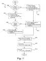
- FIG. 7is a flow chart of an exemplary authentication method for using a device in accordance with the present invention.
- FIG. 8depicts one embodiment of an exemplary device for effecting secure physical and commercial transactions in a contactless manner using biometrics identity validation in accordance with the present invention
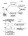
- FIG. 9depicts an exemplary environment in which the device of FIG. 8 may operate in accordance with the present invention.
- FIG. 10is a flow chart of an exemplary method for using the device of FIG. 8 in the environment of FIG. 9 in accordance with the present invention.
- FIG. 11is a diagram illustrating another embodiment of an exemplary device for effecting secure physical and commercial transactions in a contactless manner using biometrics identity validation in accordance with the present invention
- FIG. 12is an illustration of one embodiment of a biometric sensor that may be used in the device of FIG. 11 in accordance with the present invention.
- FIG. 13Aillustrates various layers that form one embodiment of the biometric sensor of FIG. 12 in accordance with the present invention
- FIG. 13Billustrates various layers that form a portion of one embodiment of the device of FIG. 11 in accordance with the present invention
- FIG. 14is a diagram of an exemplary power circuit that may be used in the device of FIG. 11 in accordance with the present invention.
- FIG. 15is a flow chart of an exemplary method for storing a template fingerprint analog in the device of FIG. 11 in accordance with the present invention.
- FIG. 16is a flow chart of an exemplary method for using the device of FIG. 11 in accordance with the present invention.
- FIG. 17is a flow chart of an exemplary method for using the device of FIG. 1 in an air transportation environment in accordance with the present invention
- FIG. 18is a flow chart of an exemplary method for using the device of FIG. 1 in a healthcare environment in accordance with the present invention
- FIG. 19is flow chart of an exemplary method for storing a biometric template analog in the device of FIG. 8 in accordance with the present invention.
- FIG. 20is a flow chart of an exemplary method for using the device of FIG. 8 in a financial transaction in accordance with the present invention
- FIG. 21is a flow chart illustrating an authentication process in accordance with one embodiment of the present invention.
- FIG. 22illustrates an authentication module constructed in accordance with one embodiment of the present invention
- FIG. 23is a functional diagram of an authentication module constructed in accordance with one embodiment of the present invention.
- FIG. 24is a block diagram of an electronic ticketing system in accordance with one embodiment of the present invention.
- FIGS. 25A , 25 B and 25 Care flowcharts illustrating various methods of operation of an electronic ticketing system in accordance with one embodiment of the present invention.
- an apparatussuch as an electronic card, ticket or information carrier, contains validated biometric data about a user.
- event access informationis stored on the electronic card or ticket by an entity authorized by the event provider.
- the useris allowed access to the event when the biometric data stored on the electronic card or ticket matches the user's biometric data and the event access information is validated.
- the user's biometric datais authenticated via a biometric sensor on the electronic card or ticket.
- the user's biometric datacan also be authenticated by the entity granting access to the event.
- the present inventionprovides a system, method and apparatus for a practical and secure card or device that has the advantages of a smart card and will interface with existing world-wide magnetic stripe readers without the use of adapters or bridges.
- the present inventionallows for proper authentication in multiple account/application cards and devices to reduce the risk to the device holder due to loss of the device or fraudulent capture of the data within the multiple accounts on the device.
- the present inventionprovides a secure and flexible system for security and/or commercial transactions using access, credit, debit, identification, security, stored value and vendor-specific cards and/or devices.
- the present inventionas described herein provides stringent protections for magnetic stripe cards and devices through the use of on-card/device biometric authentication of the user and programmable magnetic stripes such that the data within the tracks of the stripe can be manipulated and managed by the logic within the processor/controller of the card or device.
- Thisallows magnetic stripe data to be modified or completely erased for protection of the cardholder, and then re-created on-demand by the programmable features built into the card or device.
- the datacan be stored in the on-card processor/controller and then transmitted via time-varying signal to the card reader thereby emulating the swipe of a magnetic stripe through the magnetic card reader.
- the card or devicecan provide such information via a contactless communication system.
- FIG. 3a block diagram of a system 300 for enabling transactions in accordance with one embodiment of the present invention is shown. More specifically, the present invention provides a system 300 having one or more user devices 302 , one or more system interfaces 304 operable to communicate with the user device(s) 302 and a system processor or controller 306 communicably coupled to the one or more system interfaces 304 .
- Each user device 302includes a magnetic field generator 308 that is normally inactive, a biometric sensor 310 , a memory 312 , a device processor or controller 314 and a power source 316 . Note that the memory 312 and device processor 314 may be integrated into a single integrated circuit.
- the device processor 314may also include a smart card processor and an application specific integrated circuit (“ASIC”) chip.
- the power source 316may be controlled by a power management unit 318 .
- the magnetic field generator 308 , biometric sensor 310 and memory 312are all communicably coupled to the device processor 314 .
- the magnetic field generator 308 , biometric sensor 310 , memory 312 and device processor 314are all electrically connected to the power source 316 via the power management unit 318 . If the user device 302 does not include a power management unit 318 , the magnetic field generator 308 , biometric sensor 310 , memory 312 and device processor 314 will all be electrically connected to the power source 316 .
- the device processor 314is operable to process biometric information received from the biometric sensor 310 to verify that a user is authorized to use the device 302 and activate the magnetic field generator 308 when the user is verified.
- the magnetic field generator 308emulates a programmable magnetic stripe by either creating a spatial magnetic signal or a time-varying magnetic signal for emulating data obtained from swiping a magnetic stripe card through a magnetic card reader (See FIG. 5B ).
- the spatial magnetic signalis created using a magnetic stripe either mounted on the substrate or disposed within the substrate, one or more induction coils disposed within the substrate underneath the magnetic stripe, and a controller disposed within the substrate that is connected to the one or more induction coils and operable to generate a magnetic signal via the one or more induction coils and the magnetic stripe (See FIG. 5B ).
- the magnetic signalincludes binary data to enable a transaction, such as a user name, user number, device expiration date, transaction approval/denial, etc.
- a typical magnetic stripecontains three-tracks wherein each track contains a set of magnetic data cells.
- the magnetic field generator 308may be configured to read a magnetic stripe from another device so that device 302 can replace the other device. The information read from the magnetic stripe would be stored in memory 312 for later transmission by the magnetic field generator 308 upon proper authentication.
- the biometric sensor 310may include a fingerprint sensor, retina sensor or voice sensor or other sensor device capable of detecting unique characteristics of a person that can then be compared to stored data.
- a fingerprint sensorincludes a matrix of points operable to detect high and low points corresponding to ridges and valleys of a fingerprint.
- Another example of a fingerprint sensorincludes an emitter and a detector wherein light projected by the emitter is reflected from a user's finger onto the detector.
- the biometric sensor 310When the device 302 is initialized or linked to a user, the biometric sensor 310 is used to collect biometric information about the user. This biometric information is stored as a biometric analog of the user in the memory 312 . Thereafter, and as will be described below in reference to FIG. 7 , biometric information or authentication data is obtained by the biometric sensor 310 and sent to the device processor 314 for authentication. The device processor 314 determines whether the authentication data is valid for one of the users by comparing the authentication data to the biometric template stored in memory 312 . If the authentication data is valid, the device processor 314 activates the magnetic field generator 308 and provides binary data to the magnetic field generator 308 to be transmitted as a magnetic signal.
- the magnetic field generator 308then generates the magnetic signal corresponding to the information associated with the authenticated user and the selected application.
- the device processor 314will then deactivate the magnetic field generator 308 after the magnetic field generator 308 has been active for a specified period of time. Alternatively, the device processor 314 may deactivate the magnetic field generator 308 when the biometric sensor 310 no longer detects the authorized user, or a transaction complete signal is received.
- the present inventionreduces power consumption of the device 302 and increases security by (1) keeping the magnetic field generator 308 normally inactive, (2) activating the magnetic field generator 308 and transmitting the magnetic signal only after the user has been authenticated, and (3) disabling the magnetic field generator sometime thereafter. Additional power consumption can be reduced by keeping the device 302 in a sleep or low power mode until certain activation parameters have been satisfied, such as receiving an external signal, contact with the biometric sensor 310 or a user input/command.
- the power source 316may include a battery, a piezoelectric generator, a solar panel, an electromagnetic energy converter (such as used in passive Radio Frequency Identification (“RFID”) systems), a kinetic energy converter or any combination thereof.
- the power source 316may include a battery, a power generator, a converter and a multiplexer.
- the converteris electrically connected to the power generator and operable to convert power received from the power generator into power usable by the device 302 or to charge the battery.
- the battery management unit 318is connected to the battery.
- the power multiplexeris connected to the battery management unit 318 and the converter. The power multiplexer is operable to determine whether to draw power from the battery management unit, from the converter, or from both.
- the device 302may also include a user interface 320 that is communicably coupled to the device processor 314 and electrically connected to the power source 316 (via power management unit 318 ).
- the user interface 320may include a touch pad, one or more buttons, a display, a voice sensor or other known user interfaces.
- the device 302may also include a contactless interface 322 that is communicably coupled to the device processor 314 and electrically connected to the power source 316 (via power management unit 318 ).
- the contactless interface 322may include an antenna for wireless communication, an optical transceiver or other known contactless communication methods.
- device 302may also include a smart card interface 324 that is communicably coupled to the device processor 314 and electrically connected to the power source 316 (via power management unit 318 ).
- device 302may include an optical or other type of input/output (I/O) interface 326 that is communicably coupled to the device processor 314 and electrically connected to the power source 316 (via power management unit 318 ).
- I/Oinput/output
- the components of the device 302are typically disposed within or mounted on a substrate.
- the biometric sensor 310 , user interface 320 , smart card interface 324 and optical or other I/O interface 326are typically mounted on the substrate; whereas the memory 312 , device processor 314 , power source 316 and power management unit 318 are typically disposed within the substrate.
- the magnetic field generator 308 and contactless interface 322can be mounted on the substrate or disposed within the substrate.
- the type of material used for the substrate and the resulting properties of the substratewill depend on the desired application and working environment for the device 302 . In many cases, the substrate will be a semi-flexible material, such as plastic, or a laminate material.
- the substratecan then be integrated into a card, such as an access card, a credit card, a debit card, an identification card, a mini-card, a security card, a stored value card and a vendor-specific card, etc.
- the substratemay also be integrated into a travel credential, such as a passport, an immigration card and a visa, etc.
- the substratemay be integrated into a personal communication device, such as a personal data assistant (PDA), a telecommunications device, a pager, a computer and an electronic mail transceiver, etc.
- PDApersonal data assistant
- the substratemay be integrated into a personal device/belonging, such as a watch, a jewelry, a key ring, a tag and eye glasses, etc.
- the one or more system interfaces 304may include a device initialization interface 328 , a magnetic reader 330 , a wireless communications interface (transceiver) 332 , a smart card reader 334 , or an optical or other input/output interface 336 .
- the one or more system interfaces 304are used to communicate with the user device 302 physically or contactlessly, depending on the desired application and implementation.
- Other non-system interfacesmay include a battery recharger, personal computer interface or personal data assistant (PDA).
- PDApersonal computer interface or personal data assistant
- the one or more system interfaces 304are communicably coupled to a system processor or controller 306 , which in turn may be communicably coupled to a database 338 or one or more remote systems or computers 342 via network 340 .
- Network 340may be a local area network or wide area network, such as the Internet.
- FIG. 4Athe front 400 of an exemplary embodiment of a card for enabling transactions using a biometrically enabled programmable magnetic stripe in accordance with the present invention is shown.
- the cardis shown in the form of a credit or debit card, but may also be used as an access card, an identification card, a mini-card, a security card, a stored value card and a vendor-specific card, etc.
- the front 400 of the cardincludes the issuer's name 402 , a biometric sensor 310 , a photo or I/O interface 404 (user interface 320 or other I/O interface 326 ), a smart card interface 324 , a card number 406 , an expiration date 408 , the card holder's name 410 and a hologram 412 .
- Other information and featuresmay also be placed on or within the card. As will be appreciated by those skilled in the art, the features described above can be rearranged or eliminated to fit a specific application for the card.
- FIG. 4Bthe back 450 of an exemplary embodiment of a card for enabling transactions using a biometrically enabled programmable magnetic stripe in accordance with the present invention is shown.
- the back 450 of the cardincludes the magnetic field generator 308 (programmable magnetic stripe), an area for the card holder to place an authorized signature 452 and the issuer's contact information and disclaimers 454 .
- Other information and featuresmay also be placed on or within the card. As will be appreciated by those skilled in the art, the features described above can be rearranged or eliminated to fit a specific application for the card.
- FIG. 5Aa block diagram of a programmable magnetic stripe 500 ( 308 FIG. 3 ) using multiple inductive coils 518 - 530 in accordance with one embodiment of the present invention is shown.
- the programmable magnetic stripe 500( 308 FIG. 3 ) includes a magnetic stripe 502 , multiple inductive coils 518 - 530 and a control circuit 532 .
- the magnetic stripe 502contains one or more sets of magnetic data cells 504 - 516 .
- magnetic stripe 502will typically contain three tracks or sets of magnetic data cells 504 - 516 .
- the individual inductive coils 518 - 530are mounted immediately beneath each of the binary magnetic data cells 504 - 516 .
- Each inductive coil 518 - 530is electrically connected to the control circuit 532 , which may be integrated into the device processor 314 ( FIG. 3 ).
- the control circuit 532When a positive or negative current is applied to each inductive coil 518 - 530 , it changes the polarity of the magnetized particles in the binary magnetic data cell 504 - 516 of the data track in the magnetic stripe 502 immediately above it, thereby creating a spatially varying binary code or magnetic signal in the magnetic stripe 502 material that can be read by standard magnetic card readers when such binary code is applied in accordance with ISO standards.
- FIG. 5Ba block diagram of a programmable magnetic stripe 550 ( 308 FIG. 3 ) using a single induction coil 552 for sending emulated time-varying magnetic stripe data to a magnetic card reader directly from the on-card controller in accordance with another embodiment of the present invention is shown.
- the programmable magnetic stripe 550( 308 FIG. 3 ) includes a magnetic stripe 502 , a single inductive coil 552 and a control circuit 554 .
- the magnetic stripe 502contains one or more sets of magnetic data cells 504 - 516 .
- magnetic stripe 502will typically contain three tracks or sets of magnetic data cells 504 - 516 .
- the long inductive coil 552is mounted immediately beneath the entire length of the magnetic stripe 502 and its corresponding binary magnetic data cells 504 - 516 such that a time-varying signal can be transmitted to the heads of the magnetic card reader as the card is swiped through the reader.
- the data rateis determined based on the minimum and maximum swipe speeds that standard readers can accommodate.
- the single inductive coil 552is long enough for it to be in the physical proximity of the card reader heads for the entire time period required to transmit the time-varying signal from the card to the card reader.
- the inductive coil 552is electrically connected to the control circuit 554 , which may be integrated into the device processor 314 ( FIG. 3 ).
- the inductive coil 552can be pulsed with varying currents and current directions so that the time-varying data stream of a card being swiped through the reader is emulated, thus providing the same magnetic data stream to the reader heads of the magnetic stripe reader as would be seen if a card with binary data in multiple spatially distributed data cells 504 - 516 in the magnetic stripe 502 were swiped through the reader.
- This magnetic signalwill, therefore, emulate the data that would be generated by the swipe of a magnetic stripe card with the desired information embedded in the individual data cells 504 - 516 of the stripe 502 .
- the individual data cells 504 - 516are normally empty of data.
- the cardcan be activated so that the data transfer can be started.
- the cardcan be initially activated by the authorized user using an on-card “enable button”, such as a low-power capacitance sensor, that can be built into the ring of the biometrics sensor 302 ( FIG. 3 ) and used to “wake up” the card when the user is ready to authenticate himself/herself and begin using the card.
- Authentication of the card useris time stamped for use in determining the length of time to allow transmission of the emulated data.
- the magnetic reader 330FIG.
- the card 3may have a start sentinel that signals a detector on the card to alert the card that it is in the presence of the card reader 330 ( FIG. 3 ). Once the card is alerted that it is being swiped through the reader 330 ( FIG. 3 ), it begins transmission of the emulated time-varying data from the device processor to the inductive coils 552 , thereby generating an exact emulation and transmission to the reader 330 ( FIG. 3 ) of the data that would have been produced by swiping the card through the reader 330 ( FIG. 3 ) with spatially varying data included in the individual data cells 504 - 516 .
- All such transmission of emulated card datais contingent upon valid biometric authentication of the card user, followed by detection of the card that it is in the presence of the reader head and the reader 330 ( FIG. 3 ) has recognized the start sentinel on the card so that the reader 330 ( FIG. 3 ) is ready to accept the stream of emulated data provided by the device processor.
- the transmission of data from the device processor 314 ( FIG. 3 )is suspended once the initial reading of data by the magnetic card reader 330 ( FIG. 3 ) has been completed. This action prevents skimming of card information after the basic transaction has been completed.
- a programmable magnetic card 600is equipped with inductive coils as illustrated in FIG. 5A or 5 B.
- An on-card biometrics sensor 310is incorporated to enable positive authentication of the user of the card. This is accomplished by transmitting a biometrics template from the biometrics sensor 310 to the on-card control processor 314 that performs matching operations on the template sent from the biometrics sensor 310 with a template obtained from the authorized user of the card, such authorized template being resident in the control processor 314 (memory 312 ) from initial registration of the authorized card owner and/or user.
- control processor 314then authorizes the necessary account numbers and/or card applications to be downloaded into the individual data tracks of the programmable magnetic stripe 308 (magnetic field generator; see also 502 FIGS. 5A and 5B ), which then enables the card to be used in standard card-readers throughout the existing world-wide infrastructure.
- FIG. 7a flow chart of an exemplary authentication method 700 for using a device, such as device 300 ( FIG. 3 ), in accordance with the present invention is shown.
- the devicecontains information associated with one or more users, a magnetic field generator that is normally inactive and a biometric sensor.
- the devicecan be used to enable any type of transaction, such as an access transaction, a control transaction, a financial transaction, a commercial transaction or an identification transaction.
- the deviceis normally in standby or sleep mode as shown in block 702 . If one or more activation parameters are satisfied, as determined in decision block 704 , the device is switched to active mode in block 708 . Otherwise, the device remains in standby mode as shown in block 706 .
- the one or more activation parametersmay include detecting data from the biometric sensor (e.g., 310 FIG. 3 ), detecting an external signal from an interface (e.g., 308 , 322 , 324 , 326 FIG. 3 ) or receiving data from a user interface (e.g., 320 FIG. 3 ). If authentication data is not received after the device is switched to active mode, as determined in decision block 710 , and the active period has timed out, as determined in decision block 712 , the device is switched to standby mode in block 714 and again waits for activation parameters in block 704 .
- the biometric sensore.g., 310 FIG. 3
- an external signale.g., 308 , 322 , 324 , 326 FIG. 3
- a user interfacee.g., 320 FIG. 3
- the devicecontinues to wait for authentication data to be received until the active period has timed out. If, however, authentication data is received from the biometric sensor, as determined in decision block 710 , the authentication data is verified in block 716 . The verification process determines whether the authentication data is valid for one of the users by comparing the authentication data with a stored biometric template of the one or more users that are authorized or registered to use the device. If the authentication data is not valid, as determined in decision block 718 , and the active period has timed out, as determined in decision block 712 , the device is switched to standby mode in block 714 and again waits for activation parameters in block 704 . If, however, the active mode has not timed out, as determined in decision block 712 , the device will again wait for authentication data to be received until the active period has timed out.
- the information associated with the authenticated useris accessed in block 720 and provided to the device outputs in block 722 .
- the informationcan be a simple approval or denial of the transaction, or private information of the user that is required to enable or complete the transaction.
- the device outputsmay include a magnetic field generator 308 (programmable magnetic stripe), a contactless interface 322 , a smart card interface 324 , or an optical or other I/O interface 326 .
- this stepwould involve activating the magnetic field generator 308 and generating a magnetic signal corresponding to the information associated with the authenticated user.
- the authentication step (block 716 ), the information access step (block 720 ) or the information output step (block 722 )may also display information to the user, allow the user to select the information to enable the transaction or allow the user to select the device output or interface to be used.
- the informationis cleared from the device output(s) in block 728 , the device is switched to standby mode in block 714 and the device waits for various activation parameters in block 704 . If, however, the transaction is not complete, as determined in decision block 724 and the process has not timed out, as determined in decision block 726 , the process continues to wait for the transaction to be completed.
- the processis switched to standby mode in block 714 and the device waits for various activation parameters in block 704 .
- the processcan be set to interrupt the transaction and deny it if the process times out (e.g., the magnetic field generator has been active for a specified period of time) or the biometric sensor no longer detects the authorized user.
- this methodcan be performed by a computer program, such as middleware, embodied in a computer readable medium wherein each step is implemented as one or more code segments, all of which are performed on the card/device.
- the device 800includes multiple components, such as a biometric sensor 802 , a radio frequency (“RF”) antenna 804 , a controller 806 , control buttons 808 , a dynamic information display 810 , a magnetic information media component 812 , and a RF power conversion and power management unit 814 .
- RFradio frequency
- a number of inter-component communications paths 816provide connections between various components of the device 800 .
- the RF antenna 804may perform multiple functions. For example, it may capture RF energy from a RF field emanated by a RF power source and may also support two-way communication with an associated reader/writer device (not shown).
- the antenna 804may be a single antenna capable of performing both functions or may comprise multiple antennae, with one antenna for capturing RF energy from the RF field and another antenna for supporting the two-way communication with the reader/writer device.
- the communicationsmay include, for example, authenticated identification of a person operating the device 800 , various purchases and financial transactions, air ticket booking and airport security check points, and other interactions between the device 800 and the reader/writer device. These communications may be secured using mechanisms such as data encryption. It is understood that other communications components, such as audio or optical components, may replace or supplement the antenna 804 .
- the antenna 804may be operable to function with wavelengths other than RF.
- the biometric sensor 802is used for sensing a physical attribute of a user of the device 800 and generating an analog of this physical attribute.
- the analogmay then be made available to the controller 806 .
- the biometric sensor 802is designed to sense some physical attribute of a person and extract a distinctive analog of that person. To be useful for establishing positive identification, the analog may need to be individualized sufficiently so as to be unique to every person.
- a trusted copy—a template—of the analogshould be captured. Analogs later sensed by the biometric sensor 802 may then be compared against the template analog.
- Various physical attributesmay be used for identification purposes, such as fingerprints, voice prints, and retinal or iris prints.
- the controller 806interacts with the biometric sensor 802 and other components of the device 800 to perform various functions. For example, the controller 806 may capture the analog of the physical attribute for long term storage as a trusted template analog of an authorized user, as well as for immediate comparison to a stored trusted template analog during an authentication procedure. The controller 806 may also determine whether the comparison indicates a match between the template analog and the analog captured by the biometric sensor 802 . In addition, the controller 806 may control the dynamic information display 810 , respond to input from the control buttons 808 , and control the magnetic information media component 812 . Furthermore, the controller 806 may support two-way communications with an associated reader/writer device ( FIG. 9 ) via the RF antenna 804 . The controller may be a single controller/processor or may comprise multiple controllers/processors.
- the dynamic information display 810may be used to display information to a user, as well as to enable a process with which the user may interact using the control buttons 808 .
- the magnetic information media component 812may be manipulated so that it provides information via a magnetic field.
- the RF power unit 814may convert RF radio energy to electrical energy, and may control storage and distribution of the electrical energy to the other components in the device 800 . It is understood that the device 800 may also have a battery and/or other power means to use as a backup or alternative power source for the RF power control unit 814 .
- the deviceis illustrated in an exemplary environment 900 that enables contactless interaction with a reader/writer device 902 .
- the device 800is shown with the antenna 804 , as described in reference to FIG. 8 .
- the device 902uses one or more antennae 903 to communicate with device 800 , as well as emanate a RF field 906 with the purpose of supplying power to compatible devices, such as device 800 .
- a two-way communication link 908may be established between the reader/writer device 902 and the device 800 .
- the reader/writer device 902may be in communication with other devices or with a network. Furthermore, the reader/writer device 902 may be in communication with other devices or with a network. Furthermore, the reader/writer device 902 may include the RF power source, or they may be separate devices. For the purposes of clarity, the reader/writer device 902 of the present invention example includes the RF power source, although alternate sources of RF power may be used.
- the device 800may be operated in the environment 900 using a method 1000 as follows.
- the device 800is placed into the RF field 906 emanated by the reader/writer device 902 .
- the device 800captures power from the RF field 906 , which powers up the device's 800 electronics.
- the biometric sensor 802is actuated by a user. The method of actuation may depend on the type of biometric sensor (e.g., a fingerprint for a fingerprint sensor, speaking for a voice sensor, etc.).
- an authentication processis performed by the device 800 .
- the authentication processmay depend on the type of biometric sensor. For example, the detected fingerprint or voice may be compared to a template in the memory of the device 800 .
- step 1008a determination is made as to whether the user is authenticated. If the authentication process fails to validate the user, the method 1000 may return to step 1004 . If the user is validated by the authentication process, the method continues to step 1010 , where the device 800 continues the desired transaction with the reader/writer device 902 . Once this occurs, the device 800 may be removed from the RF field 906 in step 1012 , which powers down the device 800 .
- a device 1100illustrates an implementation of the present disclosure using a form factor similar to that of a credit card.
- the credit card form factor of the device 1100includes several components, such as a fingerprint sensor 1102 , a RF antenna 1104 , a first controller 1106 , a second controller 1108 , function selector buttons 1110 , an electro-luminescent display 1112 and a magnetic strip 1114 .
- the first controller 1106is an application specific integrated circuit (“ASIC”) chip and the second controller is a smart card chip, although it is understood that the functionality of both controllers may be provided by a single controller.
- ASICapplication specific integrated circuit
- the ASIC 1106is a custom integrated circuit chip developed for use in the device 1100 .
- the ASIC 1106includes Random Access Memory (“RAM”) which may be used for temporarily storing a current fingerprint analog detected by the fingerprint sensor 1102 and for temporarily storing intermediate results of processing calculations (e.g., fingerprint comparisons, etc.).
- RAMRandom Access Memory
- the ASIC 1106may also include non-volatile memory (e.g., Flash memory or EEPROM) to store and retrieve one or more fingerprint template analogs that are used for comparison against the current fingerprint analog.
- Circuitry contained within the ASIC 1106provides an interface between the ASIC 1106 and the fingerprint sensor 1102 .
- the ASIC 1106contains a microprocessor core with dedicated program and temporary memory, enabling the ASIC 1106 to use an array of processing elements for executing instructions stored with the ASIC 1106 in parallel.
- the instructionsenable the ASIC 1106 to perform a comparison between the current fingerprint analog and a template fingerprint analog.
- Other instructions included within the ASIC 1106may provide support for an authorization signal to be sent to the smart card 1108 after an authentication process has been completed.
- the ASIC 1106may be used to drive the electroluminescent display 1112 , read the function control buttons 1110 , and drive the programmable magnetic strip 1114 .
- the smart card chip 1108may support various application programs. These applications may include, for example, storage/retrieval of personal demographics information, storage/retrieval of a digitized picture of the cardholder, an “electronic purse” functionality, financial transactions, purchases, etc.
- the smart card chip 1108may support two-way communication data transfers and may perform various encryption functions to support secure communications. In the present example, the communications and encryption are based on known standards, but proprietary protocols may be used if desired. It is envisioned that the smart card chip 1108 may support smart card interactions such as identification validation, credit card transactions, and others. Note that the control and processing functions of the device 1100 can be handled by the ASIC 1106 , the smart card chip 1108 , any combination of the ASIC 1106 and the smart card chip 1108 , or a single chip.
- the fingerprint sensor 1102is designed to detect fingerprint information and provide the detected information to other components of the device 1100 .
- the fingerprint sensor 1102comprises a polymer thick film (“PTF”) construction, which provides the fingerprint sensor 1102 with the flexibility and ruggedness needed for implementation on the device 1100 .
- PTFpolymer thick film
- the fingerprint sensor 1102comprises a matrix of points that are operable to detect high and low points corresponding to ridges and valley of a fingerprint. The points are captured and used by the ASIC 1106 to determine whether the detected fingerprint analog matches a fingerprint template analog that is stored in memory.
- the PTF sensor 1102comprises a rectangular arrangement of row electrodes 1202 and column electrodes 1204 . It is noted that more or fewer columns and rows may be included in the PTF sensor 1102 , depending on such factors as the desired resolution of the PTF sensor 1102 (e.g., the number of data points desired). Electrical connections from the row and column electrodes 1202 , 1204 may rout to the ASIC 1106 .
- a fingerprint analog detected by the PTF sensor 1102may be captured by the ASIC 1106 as a sequence of numerical values.
- the row and column electrodes 1202 , 1204may be viewed as a two dimensional matrix of pixels, with numerical values representing intersections between the row and column electrodes.
- the numerical valuesmay be associated with gray scale values, and an analog representing a fingerprint may be generated from the matrix of gray scale values. It is understood that there is no need to transform the captured analog into a visible image since the matching between the stored template fingerprint analog and the candidate fingerprint analog need not rely on a visual process. However, it is convenient to conceptualize the numerical values as an image for purposes of evaluating the sensor resolution used to support fingerprint authentication.
- the PTF sensor 1102comprises 200 row electrodes and 200 column electrodes arranged in a 1 ⁇ 2′′ by 1 ⁇ 2′′ matrix, which corresponds to a graphical resolution of 400 dpi.
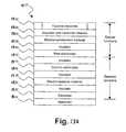
- the PTF sensor 1102is comprised of functional layers including an annularly shaped topside electrode 1302 ; an insulator with backside reflector 1304 ; and electro-luminescent layer 1306 ; insulator layers 1308 , 1312 , 1316 , and 1320 ; row electrodes 1310 ; column electrodes 1314 ; an electro-resistive layer 1318 ; and electrode 1322 ; and a substrate layer 1324 .
- the substrate layer 1324may be a portion of the substrate for the entire device 1100 .
- a user of the device 1100places a finger or thumb (henceforth only finger will be specified, although it is understood that both fingers and thumb are intended) on the surface of the PTF sensor 1102 , the finger contacts the topside electrode 1302 and becomes electrically grounded to the topside electrode 1302 .
- a voltageis applied to row electrodes 1310 , and electric field is generated between the row electrodes 1310 and the topside electrode 1302 .
- the strength of the generated fieldvaries depending on how close the finger is to the topside electrode 1302 .
- fingerprint ridgesmay be relatively close to the topside electrode 1302 of the PTF sensor 1102 , varying the generated field in a detectable manner.
- Fingerprint valleysmay be more distant form the PTF sensor 1102 than the fingerprint ridges, which may vary the generated field in a detectable manner that may be differentiated from the variations caused by the fingerprint ridges.
- the electro-luminescent layer 1306may emit more or less light as the electric field that impinges upon it varies, thereby generating an analog of the fingerprint incident upon the PTF sensor 1102 .
- the reflector component of the insulator with backside reflector layer 1304serves to reflect the omni directional light emitted by the electro-luminescent layer 1306 and thus intensify the fingerprint analog.
- the PTF sensor 1102may be operated by applying a bias voltage to only one row electrode at a time, successively biasing and unbiasing one row after another. This has the effect of causing the electro-luminescent layer 1306 to generate an analog of an elongated thin strip of the fingerprint. By sensing each of these analogs and combining them upon completion of row sequencing, a complete analog may be collected.
- the electro-resistive layer 1318It is a property of the electro-resistive layer 1318 that when it is placed in an electrical field its resistance varies with the intensity of light incident upon it.
- the light emitted by the electro-luminescent layer 1306which is an analog of the fingerprint, passes through the intervening layers 1308 , 1310 , 1312 , 1314 , and 1316 to impinge upon the electro-resistive layer 1318 .
- the electro-resistive layer 1318is placed in an electric field by placing a DC voltage bias on the electrode 1322 relative to the column electrodes 1314 , causing the electro-resistive layer to exhibit varying resistance depending upon the intensity of light incident upon it and thereby forming an analog of the fingerprint.
- a voltageis applied to the column electrodes 1314 , and the impedance between the column electrodes 1314 and the electrode 1322 can be measured.
- This measured impedanceis directly related to the varying resistance of the lector-resistive layer 1318 and hence an analog of the fingerprint. So by activating each row electrode in succession, as described above, an analog of the fingerprint can be captured and stored.
- the ASIC 1106may control the sequential activation of the row electrodes 1310 , the reading back of the varying resistance from the column electrodes 1314 , and other functions of the PTF sensor 1102 . It is understood that other approaches may be used, such as reading one column at a time for each row or reading multiple row/columns at once. Furthermore, while the preceding description focuses on the use of the PTF sensor 1102 as a fingerprint sensor, the principle of operation of the PTF sensor 1102 is general and not limited to capturing fingerprint analogs.
- FIG. 13Bone embodiment of a portion of the device 1100 illustrates the biometric sensor 1102 , display 1112 , and RF antenna 1104 formed on the substrate 1324 .
- the biometric sensorincludes layers 1302 - 1322 as described with respect to FIG. 10
- the display 1112comprises layer 1326 - 1336
- the RF antennacomprises layers 1338 - 1348 .
- each of the components 1102 , 1112 , 1104share a number of layers (e.g., 1322 , 1336 , and 1348 ). This sharing simplifies the design of the device 1100 and may also reduce manufacturing costs.
- the RF antenna 1104may capture RF energy from a RF field emanated by a RF power source and may also support two-way communication with an associated reader/writer device (not shown). The RF energy which is captured is converted to electrical energy and accumulated within the device 1100 .
- a rechargeable batterymay power the electronic components when no RF energy field is present. Such a battery may be charged via a RF energy field or alternative charging means.
- the electro-luminescent display 1112provides the capability to display information to a user of the device 1100 .
- the informationmay include a credit card number to support “card not present” transactions, a residual balance of an “electronic purse,” air travel flight and seat assignment information, and similar information.
- interaction with the display 1112may be accomplished via the function control buttons 1110 .
- the buttons 1110may be used to select a credit card number (if the device 1100 stores multiple numbers) viewed via the display 1112 or to enter a personal identification number.
- the pliability of the electro-luminescent display 1112aids its use in the card-like form factor of the device 1100 . While two control buttons 1110 are illustrated, it is understood that other numbers and configurations of function control buttons may be used.
- a dynamic magnetic strip 1114is provided to provide compatibility with existing reader devices.
- the dynamic magnetic strip 1114may be used in either fixed or dynamic mode. In dynamic mode, magnetically stored information—such as a credit card number—may be changed under control of the ASIC 1106 .
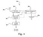
- an illustrative power circuit 1400such as may be used in the device 1100 of FIG. 11 , is depicted.
- the RF energycouples into a RF antenna 1402 (also referred to herein as a power generator).
- a RF-to-DC power converter 1404which includes a full-wave rectifier to convert the AC RF field into a DC-like circuit. Capacitance may be provided to buffer the AC peak variations into a DC-like source.
- the intermediate power generated by this processmay be used for a variety of purposes, such as charging a battery 1406 if the battery 1406 is below its full capacity and feeding power to the device 1100 .
- the battery 1406may be charged through a battery management unit 1408 .
- a smart power multiplexer 1410may be used to determine whether to draw power from the battery management unit 1408 , directly from the RF-to-DC power converter 1404 , or from both.
- a voltage regulator 1412creates a stable DC voltage level to power the device 1100 .
- the RF-to-DC converter 1404may not function and power may be drawn from the battery management unit 1408 by the smart power multiplexer 1410 .
- the voltage regulator 1112creates a stable DC voltage level to power the device 1100 .
- the power circuit 1400may not employ a battery or rechargeable battery, and may relay solely on power captured from the RF field.
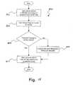
- an exemplary template storage method 1500illustrates one embodiment for capturing and storing a template of a fingerprint analog for the device 1100 of FIG. 11 .
- a userplaces the device 1100 in a RF field emanated by a reader/writer device. As described previously, the device 1100 captures power from the RF field.
- the userplaces his thumb or finger on the finger print sensor 1102 and, in step 1506 , the device 1100 determines whether a template fingerprint analog is already stored. If it is determined that no template fingerprint analog is stored, the method 1500 continues to step 1508 .
- step 1508the user's incident fingerprint is sensed by the fingerprint sensor 1102 , a fingerprint analog is generated by the fingerprint sensor 1102 , and the ASIC 1106 stores the fingerprint analog as a template fingerprint analog. If a fingerprint template analog is already stored, the method 1500 continues to step 1510 , where the device 1100 is removed from the RF field. It is understood that other events may occur before step 1510 if a fingerprint template analog is already stored, such are illustrated in FIG. 16 .
- multiple template fingerprint analogsmay be stored in the device 1100 .
- the template fingerprint analogsmay represent multiple fingerprints of a single person or may represent the fingerprints of different people. This may be accomplished, for example, by implementing a method for allowing the device 1100 's owner to securely control initialization of multiple template fingerprint analogs and to selectively engage which template fingerprint analog will be used to authenticate identity and authorize transactions. Alternately, if the device 1100 is to be used in environments requiring higher security, the user of the device 1100 may need to appear in person and validate his or her identify using traditional methods (e.g., a driver's license, birth certificate, etc.). After validation, the user's template fingerprint analog may be place into the device 1000 as described above or through other means (e.g., a scanner that transfers the template fingerprint analog into the device 1000 ).
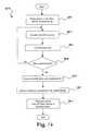
- a method 1600illustrates one method of operation for the device 1100 .
- the device 1100is placed into a RF field emanated by a reader/writer device. When placed into the RF field, the device 1100 captures power, energizing its electronics.
- a userplaces one of his fingers onto the fingerprint sensor 1102 . As described above, the fingerprint sensor 1102 captures an analog of the fingerprint and passes the analog to the SAIC 1106 .
- step 1606an authentication process is performed by comparing the captured fingerprint analog to one or more template fingerprint analogs stored in memory.
- step 1608a determination is made as to whether the user is authentication (e.g., whether the captured fingerprint analog matches a stored template fingerprint analog). If the authentication process fails to validate the user, the method 1600 may return to step 1604 as shown or may end, requiring the user to remove the device 1100 from the RF field and begin again with step 1602 . If the user is validated by the authentication process, the method continues to step 1610 , where the device 1100 conducts a communications handshake process with the reader/writer device via a contactless two-way communication link. In step 1612 , the device 1100 continues the desired transaction with the reader/writer device. Once this occurs, the device 1100 may be removed from the RF field, which powers down the device 1100 .
- a method 1700illustrates using the present disclosure in an air transportation environment.
- a traveler desiring to make a remote reservationpresents a device (such as the device 800 of FIG. 8 ) to a reader/writer device.
- the reader/writer deviceis attached to a personal computer (“PC”) via a wired or wireless connection.
- the PCmay enable the traveler to access an application, such as a web based flight reservation application.
- step 1702a determination is made as to whether the traveler has selected a remote reservation and ticketing process. If the traveler has selected such a process, the method 1700 continues to step 1704 , where the device 800 is used in conjunction with PC and the reader/writer to verify the traveler's identification and approve the transaction and associated payments. In addition, flight information may be transferred from the reader/writer device into the device 800 .
- the method 1700then continues to step 1706 , where a determination is made as to whether the traveler has selected to remotely check-in baggage. If the traveler has not selected to remotely check-in baggage, the method 1700 continues to step 1712 . If the traveler has selected to remotely check-in baggage, the method 1700 continues to step 1708 , where the device 800 is used in conjunction with PC and the reader/writer to verify the traveler's identification. In addition, flight and ticket information may be read from the device 800 to further automate the baggage check-in process. After the traveler has entered any desired information (e.g., number of bags, etc.), baggage reference information may be transferred into the traveler's device 800 for later transfer into and use by the airline's ticketing and baggage tracking systems.
- desired informatione.g., number of bags, etc.
- step 1710the traveler may use the device 800 with a reader/writer device at a counter or self-service kiosk in a manner similar to the process of the remote check-in of step 1704 . More specifically, the traveler may use the device 800 to verify the traveler's identification and approve a purchase transaction, as well as any associated payments. In addition, flight information may be transferred from the reader/writer device into the device 800 .
- the travelermay use the device 800 with the reader/writer device at the counter or self-service kiosk in a manner similar to the process of the remote baggage check-in of step 1708 . More specifically, the traveler may use the device 800 to verify the traveler's identification, provide flight and ticket information, and store baggage reference information that is transferred from the reader/writer device.
- the method 1700continues to steps 1714 , 1716 , and 1718 , where the traveler may present the device 800 to other reader/writer devices for identification and ticket authentication. For example, this may occur at security checkpoints, gates, and/or at boarding. It is understood that some of the reader/writer devices may be in communication with airline and/or government databases.
- a method 1800illustrates using the present disclosure in a health care environment.
- a determinationis made as to whether a patient desires to perform a pre check-in process before arriving at a healthcare facility. If it is determined that the patient does desire to perform a pre check-in process, the method 1800 continues to step 1804 , where the patient may present a device (such as the device 800 of FIG. 8 ) to a reader/writer device.
- the reader/writer deviceis attached to a personal computer via a wired or wireless connection.
- the PCmay enable the patient to access an application, such as a wed-based healthcare application.
- the patientmay be identified, payment and care instructions may be approved, and medical information (e.g., records, prescriptions, etc.) may be activated.
- medical informatione.g., records, prescriptions, etc.
- the device 800may also be used to provide the patient with medical alerts.
- step 1806if the patient has not performed the pre check-in process of step 1804 , the patient may use the device 800 to perform similar functions at the healthcare facility.
- the methodthen continues to step 1808 , where the device may be used to access provider services.
- the device 800may be used to interact with a reader/writer device at a desk or workstation in the healthcare facility (e.g., an examination room). This interaction may authenticate the patient's identification, provide access to pertinent medical records, verify that the records are updated, and store one or more prescriptions.
- the patientmay present the device 800 to a reader/writer device at a pharmacy.
- the device 800may be used to authenticate the patient's identification for a prescription and provide the prescription to the pharmacy. Furthermore, the device 800 may provide insurance/payment information and enable the patient to approve the transaction.
- methods 1900 and 2000illustrate using the present disclosure in a financial transaction environment.
- the financial transaction environmentincludes making retail purchases in either a physical store or on-line (e.g., over the Internet).
- the present disclosuremay be implemented in the financial transaction environment by using a device, such as the device 800 of FIG. 8 , to identify buyers, verify the identity of the buyer rapidly in a localized venue, associate the buyer's identity with a credit or debit account, and/or assure the availability and legitimacy of funds in these accounts for payment transactions.
- Payments for retail purchasesare generally accomplished in one of three ways: with cash; with a check; or with a credit or debit card.
- a cash transactionthere is generally no need for validating the identification of the buyer.
- a checkIn a transaction where a check is used, there generally is a need for identification of the buyer. This identification may occur by way of the buyer's presentation of a driver's license or alternate, approved identification card, presentation of a credit card to indicate credit-worthiness, or by a telecommunication connection to check security processing service to assure fund availability for, and legitimacy of, the check presented for payment.
- the device 800Before the device 800 is usable in financial transactions, it should be initialized by the buyer/owner with the registration of a selected fingerprint pattern into secured memory of the device 800 .
- the device ownerholds the device 800 in the RF field generated by a point of sale (“POS”) device, which may be a kiosk, personal computer, cash register, or similar device.
- POSpoint of sale
- the RF energy from the POS deviceprovides for the power of the device 800 and display activation in step 1902 .
- a determinationis made as to whether the device 800 has been previously used. For example, the device 800 may determine if a fingerprint template analog is already stored in memory. If the device 800 has been previously used, the method 1900 ends.
- the device 800continues to step 1906 , where the owner is prompted to actuate the biometric sensor. For example, this may entail the owner briefly touching the biometric sensor 802 on the device 800 with a selected finger or thumb.
- the fingerprint informationis read from the biometric sensor 802 and stored in the device 800 in steps 1908 , 1910 while the owner maintains contact with the biometric sensor 802 .
- the ownermay maintain contact with the biometric sensor 802 until, in step 1912 , an acknowledgement is displayed on the display 810 that the fingerprint pattern has been successfully registered in the device 800 as an encrypted template.
- the user of the device 800holds the device 800 within a RF field generated by a RF reader connected to the POS device in step 2002 .
- the usermay hold the device 800 at an approximate six inch distance from the RF reader.
- the useractuates the biometric sensor 802 (e.g., touches the fingerprint sensor with his/her finger or thumb) to effect a comparative match with his/her previously registered fingerprint securely stored in the memory of the card.
- a successful matcheffects an encrypted approval and transfer of cardholder account data to the seller's administrative account receivables processing system.
- step 2006a determination is made as to whether the user desires to transfer electronic receipt information to the device 800 . If not, the method 2000 continues to step 2010 , where the device 800 is removed from the RF field. If it is determined in step 2006 that the user does want to transfer electronic receipt information to the device 800 , the method 2000 continues to step 2008 , where the device 800 stores the information in memory. The method 2000 may then continue to step 2008 , where the device 800 is removed from the RF field.
- FIG. 21illustrates a flowchart of an authentication process 2100 in accordance with one embodiment of the present invention.
- a userinitially acquires an access card, electronic ticket, smart card, user device or other such information carrier (see e.g., FIGS. 4A , 4 B, 6 , 8 and 11 ) from a central distribution site.
- the smart cardis preloaded with the user's identifying information (e.g., fingerprint), a unique identifier code (“UIC”), ticket information, and/or validity information.
- identifying informatione.g., fingerprint
- UICCunique identifier code
- This informationcan also be stored at a central database; although in one embodiment, the identifying information is only stored on the smart card after registration of the biometric data (e.g., fingerprint) on the smart card has been validated.
- biometric datae.g., fingerprint
- an agent at an airline ticket counterauthenticates the identity of the user by examining the user's government issued ID card before storing the identifying information on the smart card.
- the userpresents his smart card to an appropriate smart card reader in block 2105 .
- the readercan verify the validity of the smart card using any of a variety of known techniques in block 2110 .
- the readercan present the smart card with a challenge (e.g., random number) that the smart card must mathematically manipulate to form an answer to the challenge. If that answer is correct, the reader determines that the smart card is valid.
- simple validity checkscan be done using serial numbers, expiration dates, use restrictions, etc.
- identifying informatione.g., fingerprint, palm print, retinal scan, voice print, etc.
- This acquired identifying information or biometric datais compared against the identifying information stored on the smart card to determine if the two sets of information match in decision block 2135 .
- the user's identityis verified in block 2140 and, if appropriate, access granted to the event.
- servicescan be provided to the user. For example, Internet purchasing can be enabled, Internet-based voting can be enabled, government benefits (e.g., WIC, food stamps) can be used, driver's licenses can be verified.
- the smart card(or the central database) is also read to determine if the user has the right to enter the event.
- the smart cardmay be read to verify that the user has the right to enter the sporting event.
- a central databasecan be searched using the UIC read from the smart card to determine if the user has the right to enter the sporting event.
- the usercan update the smart card data to include additional events. For example, the user can purchase a particular ticket and have that information directly written to the smart card, or alternatively, the user can purchase a ticket on-line and have that information written to the central database.
- the user's identitycan not be verified, and the user is denied access in block 2145 .
- the usermay be given another chance to verify his identity.
- an incorrect match or multiple incorrect matches of identity informationcan result in the smart card being permanently invalidated by, for example, writing an invalidity indicator to a field on the smart card.
- the central databasecould be modified to indicate that any smart card associated with the UIC is invalid.
- the authentication module 2200includes a smart card reader 2205 for receiving a smart card and reading data (e.g., fingerprint data, UIC, validity fields, etc.) therefrom.
- datae.g., fingerprint data, UIC, validity fields, etc.
- the smart card reader 2205 illustrated in FIG. 22is a typical contact-style reader, other embodiments include contact-less readers (e.g., infrared (IR) readers, radio frequency (RF) readers, proximity readers, etc.) for reading information from a smart card.
- IRinfrared
- RFradio frequency
- the authentication module 2200includes a fingerprint sensor 2210 (although it could be any type of identity sensor.)
- the fingerprint sensor 2210is configured to read the user's fingerprint and verify that the read fingerprint matches the fingerprint data read from the smart card. Assuming that the fingerprints match, an approval indicator can be displayed on the LCD display 2220 and/or LEDs 2215 .
- the LCD display 2220 and the LEDs 2215can be used to indicate an error in reading the data or an incorrect match of fingerprints—thereby prompting the user to reinsert the smart card and/or to reprovide his fingerprint to the fingerprint sensor.
- FIG. 23there is illustrated a functional diagram of an authentication module 2300 that is similar to the module 2200 shown in FIG. 22 .
- the authentication module 2300includes two input devices: a smart card interface 2315 for reading a smart card 2305 and a fingerprint sensor 310 for reading the cardholder's fingerprint.
- the authentication module 2300could also receive information from a network-connected central storage device 2312 that is connected to the authentication module 2300 .
- the card interface 2315reads data from the smart card 2305 and passes that information to the embedded microcontroller 2320 . Moreover, the embedded microcontroller 2320 may generate a challenge that the card interface 2315 passes to the smart card 2305 . Depending upon the smart card's response to the challenge, the embedded microcontroller 2320 can verify the authenticity of the smart card 2305 . Additionally, the card interface 2315 can read other data from the smart card 2305 including expiration data, validity fields and ticket information. This data can be used to determine whether the smart card is valid and whether the cardholder can access a particular event.
- the card interface 2315reads the fingerprint stored on the smart card 2305 and passes it to the fingerprint acquisition and verification module 2325 (the “fingerprint module”).
- the fingerprint module 2325compares the fingerprint read from the smart card 2305 with the fingerprint read by the fingerprint sensor 2310 . If the two fingerprints match, the user interface 2340 notifies the user (and security personnel) that his identity has been verified. If, however, the two fingerprints do not match, the user interface 2340 may notify the user (and security personnel) that the user's identity cannot be verified. The user can then be requested to attempt verification again. In one embodiment, the user is given a limited number of attempts to verify his identity before his smart card is permanently invalidated.
- the authentication module 2300also includes local storage 2335 for storing transaction information.
- local storage 2335can store the UIC for each smart card 2305 read by the card interface 2315 , the time of the transaction, whether identity was verified, etc. This information can be transferred to a central facility (not shown) using the communication interface 2330 . Once received at the central facility, this information can be used for a variety of purposes including marketing, further security checks, ticket verification, luggage matching, etc.
- the UICis transferred from the authentication module 2300 to the central facility where the customer's account is accessed wherein the customer's account may include a list of the tickets that a customer has purchased.
- the customerAssuming that the customer has purchased a ticket for the event associated with the authentication module 2300 , then the customer, whose ID was previously verified, is allowed access. Thus, two checks are performed prior to allowing a customer access to an event. First, the identity of the customer is verified, and second, the right of the customer to enter the event is verified.
- the list of tickets that a customer has purchasedis stored directly on the smart card rather than at a central database.
- all information that the authentication module 2300 needs to grant/deny the cardholder access to an eventis stored directly on the smart card.
- each authentication module 2300could act as a stand-alone unit.
- the identification featurecan be disabled so that the smart card could be used as a ticket and transferred freely between people.
- FIG. 24a block diagram of an electronic ticketing system 2400 in accordance with one embodiment of the present invention is shown.
- the electronic ticketing system 2400relies on a user device 2402 , which has been previously described as an access card, electronic ticket, smart card, user device or other such information carrier (see e.g., FIGS. 4A , 4 B, 6 , 8 and 11 ).
- the user device 2402is an apparatus that includes a substrate, a communications interface disposed within the substrate, a biometric sensor mounted on the substrate, a memory disposed within the substrate, event access information 2406 stored in the memory and a processor disposed within the substrate that is communicably coupled to the communications interface, the biometric sensor and the memory.
- the processoris operable to process biometric information received from the biometric sensor to verify that a user is authorized to use the apparatus and transmit the event access information 2406 and an indication that the user is authorized to use the apparatus via the communications interface when the user is verified.
- a power sourceis also disposed within the substrate and electrically connected to the communications interface, the biometric sensor and the processor.
- the communications interfacemay include a wireless transceiver, an optical transmitter, a magnetic stripe, a programmable magnetic stripe or magnetic field generator that is normally inactive, a smart card interface or communications port.
- the magnetic field generatorcan create a spatial magnetic signal using a magnetic stripe and one or more induction coils, or create a time-varying magnetic signal for emulating data obtained from swiping a magnetic stripe card through a magnetic card reader.
- the user of the device 2402purchases a ticket or obtains authorization to access an event from a ticket purchase or authentication station 2404 .
- the userwill present various forms of personal identification before the event access information 2406 will be provided.
- the userprovides personal identification information to verify the identity of the user prior to receiving the event access information.
- the usermay also have to validate that he or she is the authorized user of the device 2402 using the biometric sensor on the device 2402 as previously described (e.g., personal ID information checked against registered biometric data).
- the usermay only have to purchase the ticket.
- the ticket purchase or authentication station 2404will provide or deny the event access information 2406 based on local information or on information obtained or verified using the system processor 2408 and/or other external systems 2410 , such as state and federal databases. Once the user is properly validated, the event access information 2406 is transmitted to the user device 2402 where it is stored in memory.
- the event access information 2406may be encrypted or otherwise coded to prevent fraudulent use or copying of the event access information 2406 .
- the userattempts to gain access to the event by validating that he or she is the authorized user of the device 2402 using the biometric sensor on the device 2402 as previously described. If the user is authenticated, the user device 2402 transmits the event access information and user validation 2412 to the event access station 2414 .
- the user validationis an indicator that the user is authorized to use the device 2412 .
- the event access station 2414validates the event access information 2406 either locally or via system processor 2408 . If the event access information 2406 is valid, the user is granted access to the event. Otherwise, the user may retry to gain access with the device 2402 , or try to authenticate his or her association to the event access information 2406 via external biometric sensors or other identification means, or be subject to further security checks/inquiry. Note that the device 2402 may also transmit an indication that the user is not authorized to use the device 2402 when the user is not properly authenticated.
- the present inventionprovides a system having one or more user devices 2402 , one or more system interfaces 2404 and 2414 operable to communicate with the user device 2402 and a system processor 2408 communicably coupled to the one or more system interfaces 2404 and 2414 .
- Each user device 2402includes a substrate, a communications interface disposed within the substrate, a biometric sensor mounted on the substrate, a memory disposed within the substrate, event access information 2406 stored in the memory and a device processor disposed within the substrate and communicably coupled to the communications interface, the biometric sensor and the memory.
- the device processoris operable to process biometric information received from the biometric sensor to verify that a user is authorized to use the apparatus and transmit the event access information 2406 and an indication that the user is authorized to use the user device 2402 when the user is verified.
- the user device 2402also includes a power source disposed within the substrate and electrically connected to the communications interface, the biometric sensor and the device processor.
- the one or more system interfaces 2404 and 2414may include an optical interface, a smart card interface, a wireless communication interface, a magnetic reader, an initialization interface, a recharger or other communication port.
- a databasemay be communicably coupled to the system processor 2408 .
- one or more remote computers or external systemscan be communicably coupled to the system processor 2408 via one or more networks or direct connections.
- FIG. 25Aillustrates the process 2500 to validate the user and provide the event access information to the user device.
- the processstarts by determining the identity and access rights of a user to the event in block 2502 . This may include purchasing the ticket, providing a photo ID, providing biometric information or undergoing a security or background check. If access is to be granted, as determined in decision block 2504 , the event access information 2406 is created in block 2506 .
- the event access informationis then transmitted to the user device via the communication interfaces (physical or wireless) and stored in the memory of the user device in block 2508 .
- the access informationcan be encrypted or otherwise coded to prevent unauthorized use of the information. If, however, access is not to be granted, as determined in decision block 2504 , access to the event is denied in block 2510 and various checks can be made on the user device or the security rating of the user in block 2512 .
- the methodcan be performed by a computer program, such as middleware, embodied in a computer readable medium wherein each step is implemented as one or more code segments.
- FIG. 25Billustrates the process 2530 to request access to an event using the user device.
- the processstarts by receiving event access information from an external source via the communications interface and storing the access information in the memory in block 2532 .
- Authentication datais then received from the biometric sensor in block 2534 as previously described for on-card biometric authentication. If the authentication data is valid for the user, as determined in decision block 2536 , access to the event is requested by transmitting the event access information and an indication that the user is authorized to use the apparatus via the communications interface in block 2538 . If, however, the authentication data is not valid, as determined in decision block 2536 , the event access information is not transmitted in block 2540 . Alternatively, a access denial indication can be transmitted.
- the methodcan be performed by a computer program, such as middleware, embodied in a computer readable medium wherein each step is implemented as one or more code segments.
- FIG. 25Cillustrates the process 2560 for granting access to an event.
- the process 2560starts by receiving access information and an indication that the user is authorized to use the apparatus from the communications interface in block 2562 . If the event access information is valid (e.g., access information indicates that access rights to the event are associated with the apparatus), as determined in decision block 2564 , access to the event is granted in block 2566 . If, however, the event access information is not valid, as determined in decision block 2564 , the user is denied access to the event in block 2568 and additional device or security checks can be performed in block 2570 . The user is authorized to use the apparatus whenever the apparatus determines that authentication data received from the biometric sensor is valid for the user.
- the methodcan be performed by a computer program, such as middleware, embodied in a computer readable medium wherein each step is implemented as one or more code segments.
Landscapes
- Engineering & Computer Science (AREA)
- Business, Economics & Management (AREA)
- Physics & Mathematics (AREA)
- General Physics & Mathematics (AREA)
- Accounting & Taxation (AREA)
- Strategic Management (AREA)
- General Business, Economics & Management (AREA)
- Theoretical Computer Science (AREA)
- Computer Networks & Wireless Communication (AREA)
- Human Computer Interaction (AREA)
- Computer Security & Cryptography (AREA)
- Finance (AREA)
- Microelectronics & Electronic Packaging (AREA)
- Storage Device Security (AREA)
- Credit Cards Or The Like (AREA)
Abstract
Description
Claims (45)
Priority Applications (1)
| Application Number | Priority Date | Filing Date | Title |
|---|---|---|---|
| US10/737,080US8103881B2 (en) | 2000-11-06 | 2003-12-16 | System, method and apparatus for electronic ticketing |
Applications Claiming Priority (5)
| Application Number | Priority Date | Filing Date | Title |
|---|---|---|---|
| US70755900A | 2000-11-06 | 2000-11-06 | |
| US36836302P | 2002-03-28 | 2002-03-28 | |
| US10/400,306US7337326B2 (en) | 2002-03-28 | 2003-03-27 | Apparatus and method for effecting secure physical and commercial transactions in a contactless manner using biometric identity validation |
| US10/680,050US8015592B2 (en) | 2002-03-28 | 2003-10-07 | System, method and apparatus for enabling transactions using a biometrically enabled programmable magnetic stripe |
| US10/737,080US8103881B2 (en) | 2000-11-06 | 2003-12-16 | System, method and apparatus for electronic ticketing |
Related Parent Applications (2)
| Application Number | Title | Priority Date | Filing Date |
|---|---|---|---|
| US70755900AContinuation-In-Part | 2000-11-06 | 2000-11-06 | |
| US10/680,050Continuation-In-PartUS8015592B2 (en) | 2000-11-06 | 2003-10-07 | System, method and apparatus for enabling transactions using a biometrically enabled programmable magnetic stripe |
Publications (2)
| Publication Number | Publication Date |
|---|---|
| US20050001711A1 US20050001711A1 (en) | 2005-01-06 |
| US8103881B2true US8103881B2 (en) | 2012-01-24 |
Family
ID=33556618
Family Applications (1)
| Application Number | Title | Priority Date | Filing Date |
|---|---|---|---|
| US10/737,080Expired - Fee RelatedUS8103881B2 (en) | 2000-11-06 | 2003-12-16 | System, method and apparatus for electronic ticketing |
Country Status (1)
| Country | Link |
|---|---|
| US (1) | US8103881B2 (en) |
Cited By (19)
| Publication number | Priority date | Publication date | Assignee | Title |
|---|---|---|---|---|
| US20070094742A1 (en)* | 2005-10-25 | 2007-04-26 | Seiko Epson Corporation | Information display device |
| US20090159696A1 (en)* | 2007-12-24 | 2009-06-25 | Dynamics Inc. | Advanced dynamic credit cards |
| US20100037030A1 (en)* | 2008-08-05 | 2010-02-11 | Fujitsu Limited | Archive apparatus, unauthorized access detection method, and unauthorized access detection program |
| US20110135092A1 (en)* | 2008-06-18 | 2011-06-09 | Keba Ag | Method and device for proctecting a reading device for card-shaped data carriers from unauthorized evaluation or copying of magnetically encoded data of an inserted card-shaped data carrier |
| US20140098233A1 (en)* | 2012-10-05 | 2014-04-10 | Sensormatic Electronics, LLC | Access Control Reader with Audio Spatial Filtering |
| US20140278521A1 (en)* | 2007-04-12 | 2014-09-18 | Epic Systems Corporation | Location limited check-in kiosk method and apparatus |
| US9396380B2 (en)* | 2014-07-28 | 2016-07-19 | Google Technology Holdings LLC | Finger print sensor and auxiliary processor integration in an electronic device |
| US20160292669A1 (en)* | 2015-04-03 | 2016-10-06 | NXT-ID, Inc. | System and Method for Low-Power Close-Proximity Communications and Energy Transfer Using a Miniture Multi-Purpose Antenna |
| US9471239B2 (en) | 2014-03-28 | 2016-10-18 | International Business Machines Corporation | Memory power management and data consolidation |
| WO2016166376A1 (en) | 2015-04-17 | 2016-10-20 | Cardlab Aps | A device for outputting a magnetic field and a method of outputting a magnetic field |
| US10243088B1 (en)* | 2017-12-21 | 2019-03-26 | Capital One Services, Llc | Transaction card for transferring solar power |
| US10515320B2 (en) | 2016-09-20 | 2019-12-24 | International Business Machines Corporation | Biometric verification of ticket users |
| US10614351B2 (en) | 2014-12-19 | 2020-04-07 | Cardlab Aps | Method and an assembly for generating a magnetic field and a method of manufacturing an assembly |
| US10803370B2 (en) | 2005-02-22 | 2020-10-13 | Tyfone, Inc. | Provisioning wearable device with current carrying conductor to produce time-varying magnetic field |
| US11398122B2 (en) | 2017-04-28 | 2022-07-26 | 1 Micro, LLC | Passenger authentication system for a transportation service vehicle |
| US11694053B2 (en) | 2008-08-08 | 2023-07-04 | Icashe, Inc. | Method and apparatus for transmitting data via NFC for mobile applications including mobile payments and ticketing |
| US20240119455A1 (en)* | 2016-07-22 | 2024-04-11 | Wells Fargo Bank, N.A. | Piezoelectric biometric card security |
| US12147863B2 (en) | 2008-08-08 | 2024-11-19 | Icashe, Inc. | Method and apparatus for transmitting data via NFC for mobile applications including mobile payments and ticketing |
| US12282819B1 (en)* | 2009-10-12 | 2025-04-22 | Dynamics Inc. | Magnetic stripe track signal having multiple communications channels |
Families Citing this family (166)
| Publication number | Priority date | Publication date | Assignee | Title |
|---|---|---|---|---|
| US7747507B2 (en)* | 1996-05-23 | 2010-06-29 | Ticketmaster L.L.C. | Computer controlled auction system |
| JP2001036545A (en)* | 1999-05-17 | 2001-02-09 | Sony Corp | Information processing unit, its method, information processing system and medium |
| US7343351B1 (en) | 1999-08-31 | 2008-03-11 | American Express Travel Related Services Company, Inc. | Methods and apparatus for conducting electronic transactions |
| US7953671B2 (en) | 1999-08-31 | 2011-05-31 | American Express Travel Related Services Company, Inc. | Methods and apparatus for conducting electronic transactions |
| US7505941B2 (en) | 1999-08-31 | 2009-03-17 | American Express Travel Related Services Company, Inc. | Methods and apparatus for conducting electronic transactions using biometrics |
| US7889052B2 (en) | 2001-07-10 | 2011-02-15 | Xatra Fund Mx, Llc | Authorizing payment subsequent to RF transactions |
| JP2003524841A (en)* | 2000-02-10 | 2003-08-19 | ジョン ショアー, | Apparatus, system, and method for performing wireless transaction financial transfers, electronically recordable authorized transfers, and other information transfers |
| US20020059100A1 (en)* | 2000-09-22 | 2002-05-16 | Jon Shore | Apparatus, systems and methods for customer specific receipt advertising |
| US8103881B2 (en) | 2000-11-06 | 2012-01-24 | Innovation Connection Corporation | System, method and apparatus for electronic ticketing |
| US8015592B2 (en) | 2002-03-28 | 2011-09-06 | Innovation Connection Corporation | System, method and apparatus for enabling transactions using a biometrically enabled programmable magnetic stripe |
| US7555361B2 (en)* | 2000-12-25 | 2009-06-30 | Sony Corporation | Apparatus, system and method for electronic ticket management and electronic ticket distribution authentication |
| US7237117B2 (en) | 2001-03-16 | 2007-06-26 | Kenneth P. Weiss | Universal secure registry |
| US7725427B2 (en) | 2001-05-25 | 2010-05-25 | Fred Bishop | Recurrent billing maintenance with radio frequency payment devices |
| AU2002346211B2 (en)* | 2001-06-27 | 2008-06-12 | Sony Corporation | Integrated circuit device, information processing device, information recording device memory management method, mobile terminal device, semiconductor integrated circuit device, and communication method using mobile terminal device |
| US7059531B2 (en) | 2001-07-10 | 2006-06-13 | American Express Travel Related Services Company, Inc. | Method and system for smellprint recognition biometrics on a fob |
| US7668750B2 (en)* | 2001-07-10 | 2010-02-23 | David S Bonalle | Securing RF transactions using a transactions counter |
| US20040233039A1 (en)* | 2001-07-10 | 2004-11-25 | American Express Travel Related Services Company, Inc. | System for registering a biometric for use with a transponder |
| US7705732B2 (en)* | 2001-07-10 | 2010-04-27 | Fred Bishop | Authenticating an RF transaction using a transaction counter |
| US8001054B1 (en) | 2001-07-10 | 2011-08-16 | American Express Travel Related Services Company, Inc. | System and method for generating an unpredictable number using a seeded algorithm |
| US8548927B2 (en) | 2001-07-10 | 2013-10-01 | Xatra Fund Mx, Llc | Biometric registration for facilitating an RF transaction |
| US8279042B2 (en) | 2001-07-10 | 2012-10-02 | Xatra Fund Mx, Llc | Iris scan biometrics on a payment device |
| US9024719B1 (en) | 2001-07-10 | 2015-05-05 | Xatra Fund Mx, Llc | RF transaction system and method for storing user personal data |
| US7735725B1 (en) | 2001-07-10 | 2010-06-15 | Fred Bishop | Processing an RF transaction using a routing number |
| US9031880B2 (en)* | 2001-07-10 | 2015-05-12 | Iii Holdings 1, Llc | Systems and methods for non-traditional payment using biometric data |
| US20090008441A1 (en)* | 2001-07-10 | 2009-01-08 | Xatra Fund Mx, Llc | Tracking rf transaction activity using a transaction device identifier |
| US7249112B2 (en) | 2002-07-09 | 2007-07-24 | American Express Travel Related Services Company, Inc. | System and method for assigning a funding source for a radio frequency identification device |
| US20040232224A1 (en)* | 2001-07-10 | 2004-11-25 | American Express Travel Related Services Company, Inc. | Method for registering biometric for use with a fob |
| US20040236699A1 (en) | 2001-07-10 | 2004-11-25 | American Express Travel Related Services Company, Inc. | Method and system for hand geometry recognition biometrics on a fob |
| US9454752B2 (en) | 2001-07-10 | 2016-09-27 | Chartoleaux Kg Limited Liability Company | Reload protocol at a transaction processing entity |
| US7360689B2 (en) | 2001-07-10 | 2008-04-22 | American Express Travel Related Services Company, Inc. | Method and system for proffering multiple biometrics for use with a FOB |
| US7543738B1 (en) | 2001-07-10 | 2009-06-09 | American Express Travel Related Services Company, Inc. | System and method for secure transactions manageable by a transaction account provider |
| US8294552B2 (en) | 2001-07-10 | 2012-10-23 | Xatra Fund Mx, Llc | Facial scan biometrics on a payment device |
| US7303120B2 (en)* | 2001-07-10 | 2007-12-04 | American Express Travel Related Services Company, Inc. | System for biometric security using a FOB |
| US7077313B2 (en)* | 2001-10-01 | 2006-07-18 | Avante International Technology, Inc. | Electronic voting method for optically scanned ballot |
| JP4040403B2 (en)* | 2001-11-27 | 2008-01-30 | ソニー株式会社 | Information processing apparatus and method, recording medium, and program |
| US8082575B2 (en) | 2002-03-28 | 2011-12-20 | Rampart-Id Systems, Inc. | System, method and apparatus for enabling transactions using a user enabled programmable magnetic stripe |
| US6805287B2 (en) | 2002-09-12 | 2004-10-19 | American Express Travel Related Services Company, Inc. | System and method for converting a stored value card to a credit card |
| US9477820B2 (en) | 2003-12-09 | 2016-10-25 | Live Nation Entertainment, Inc. | Systems and methods for using unique device identifiers to enhance security |
| US10366373B1 (en) | 2002-12-09 | 2019-07-30 | Live Nation Entertainment, Incorporated | Apparatus for access control and processing |
| US9740988B1 (en) | 2002-12-09 | 2017-08-22 | Live Nation Entertainment, Inc. | System and method for using unique device indentifiers to enhance security |
| US7494060B2 (en)* | 2002-12-10 | 2009-02-24 | Anthony Zagami | Information-based access control system for sea port terminals |
| KR20060009311A (en)* | 2003-05-08 | 2006-01-31 | 코닌클리즈케 필립스 일렉트로닉스 엔.브이. | Trading card, authentication system and trading method |
| US8463627B1 (en) | 2003-12-16 | 2013-06-11 | Ticketmaster | Systems and methods for queuing requests and providing queue status |
| US7543739B2 (en) | 2003-12-17 | 2009-06-09 | Qsecure, Inc. | Automated payment card fraud detection and location |
| US7641124B2 (en)* | 2003-12-17 | 2010-01-05 | Qsecure, Inc. | Magnetic data recording device |
| US20050165683A1 (en)* | 2004-01-13 | 2005-07-28 | Acquenetta Taylor | System and method for using a universal payment card for transportation vehicles for hire |
| US7406334B2 (en)* | 2004-01-26 | 2008-07-29 | Sbc Knowledge Ventures, L.P. | Systems and methods for securing personal or private content stored in the internal memory of a mobile terminal |
| US7637810B2 (en)* | 2005-08-09 | 2009-12-29 | Cfph, Llc | System and method for wireless gaming system with alerts |
| US20070060358A1 (en) | 2005-08-10 | 2007-03-15 | Amaitis Lee M | System and method for wireless gaming with location determination |
| US7534169B2 (en) | 2005-07-08 | 2009-05-19 | Cfph, Llc | System and method for wireless gaming system with user profiles |
| US8092303B2 (en) | 2004-02-25 | 2012-01-10 | Cfph, Llc | System and method for convenience gaming |
| US8616967B2 (en) | 2004-02-25 | 2013-12-31 | Cfph, Llc | System and method for convenience gaming |
| US7811172B2 (en)* | 2005-10-21 | 2010-10-12 | Cfph, Llc | System and method for wireless lottery |
| US7584123B1 (en) | 2004-04-06 | 2009-09-01 | Ticketmaster | Systems for dynamically allocating finite or unique resources |
| US20050240528A1 (en)* | 2004-04-23 | 2005-10-27 | Colin Hendrick | Smartcard with visual display |
| US7110866B1 (en)* | 2004-04-26 | 2006-09-19 | Julius Vivant Dutu | Security enhanced automatic pilot system for air vehicles |
| US20060000893A1 (en)* | 2004-07-01 | 2006-01-05 | American Express Travel Related Services Company, Inc. | Method for biometric security using a smartcard-reader |
| US7325724B2 (en) | 2004-07-01 | 2008-02-05 | American Express Travel Related Services Company, Inc. | Method for registering a biometric for use with a smartcard |
| US7363504B2 (en)* | 2004-07-01 | 2008-04-22 | American Express Travel Related Services Company, Inc. | Method and system for keystroke scan recognition biometrics on a smartcard |
| US7318550B2 (en)* | 2004-07-01 | 2008-01-15 | American Express Travel Related Services Company, Inc. | Biometric safeguard method for use with a smartcard |
| US7314164B2 (en) | 2004-07-01 | 2008-01-01 | American Express Travel Related Services Company, Inc. | System for biometric security using a smartcard |
| US7314165B2 (en) | 2004-07-01 | 2008-01-01 | American Express Travel Related Services Company, Inc. | Method and system for smellprint recognition biometrics on a smartcard |
| US7341181B2 (en) | 2004-07-01 | 2008-03-11 | American Express Travel Related Services Company, Inc. | Method for biometric security using a smartcard |
| TWI268013B (en)* | 2004-08-13 | 2006-12-01 | King House Technology Co Ltd | Contact type illuminable card and storage cassette thereof |
| EP1789905A4 (en)* | 2004-09-16 | 2016-07-27 | Cirque Corp | A contactless card reader integrated into a touchpad |
| JP4825431B2 (en)* | 2005-03-08 | 2011-11-30 | パナソニック株式会社 | Access control device |
| MX2007010467A (en)* | 2005-03-09 | 2007-10-12 | Diebold Inc | Check accepting and cash dispensing automated banking machine system and method. |
| US9608929B2 (en) | 2005-03-22 | 2017-03-28 | Live Nation Entertainment, Inc. | System and method for dynamic queue management using queue protocols |
| CA2602096A1 (en)* | 2005-03-22 | 2009-09-28 | Ticketmaster | Apparatus and methods for providing queue messaging over a network |
| US7707625B2 (en)* | 2005-03-30 | 2010-04-27 | Hid Global Corporation | Credential processing device event management |
| EP1882229B1 (en)* | 2005-04-27 | 2014-07-23 | Privasys, Inc. | Electronic cards and methods for making same |
| WO2006122098A2 (en)* | 2005-05-09 | 2006-11-16 | Addington Don W | System and method for buying and selling event tickets |
| DE102005022780B4 (en)* | 2005-05-12 | 2017-12-28 | Infineon Technologies Ag | Semiconductor chips for tag applications and method for packaging semiconductor chips |
| US7475815B2 (en)* | 2005-05-13 | 2009-01-13 | Sap Ag | Wizard for answering support inquiries |
| US8070604B2 (en) | 2005-08-09 | 2011-12-06 | Cfph, Llc | System and method for providing wireless gaming as a service application |
| US10510214B2 (en) | 2005-07-08 | 2019-12-17 | Cfph, Llc | System and method for peer-to-peer wireless gaming |
| WO2007011311A2 (en)* | 2005-07-18 | 2007-01-25 | Kristalbond Technologies (Singapore) Pte Ltd. | Biometric transponder system |
| US20070288319A1 (en)* | 2005-07-25 | 2007-12-13 | Robinson Timothy L | System and method for transferring biometrically accessed redemption rights |
| US7483862B1 (en)* | 2005-07-25 | 2009-01-27 | Yt Acquisition Corporation | System and method for prepaid biometric redemption accounts |
| JP2007058763A (en)* | 2005-08-26 | 2007-03-08 | Toshiba Corp | Admission management system and admission management method |
| US7823766B1 (en)* | 2005-09-30 | 2010-11-02 | Advanced Micro Devices, Inc. | Financial transaction system |
| US8352323B2 (en)* | 2007-11-30 | 2013-01-08 | Blaze Mobile, Inc. | Conducting an online payment transaction using an NFC enabled mobile communication device |
| CA2932591C (en) | 2006-02-07 | 2023-07-25 | Ticketmaster | Methods and systems for reducing burst usage of a networked computer system |
| US8234220B2 (en) | 2007-02-21 | 2012-07-31 | Weiss Kenneth P | Universal secure registry |
| US11227676B2 (en) | 2006-02-21 | 2022-01-18 | Universal Secure Registry, Llc | Universal secure registry |
| EP1987463A1 (en) | 2006-02-21 | 2008-11-05 | WEISS, Kenneth P. | Method and apparatus for secure access payment and identification |
| US20070231838A1 (en)* | 2006-04-03 | 2007-10-04 | Garton Andrew J | Method for the assay of rock kinase activity in cells |
| EP2016536A4 (en)* | 2006-04-18 | 2011-06-29 | Cfph Llc | Systems and methods for providing access to wireless gaming devices |
| US7549576B2 (en)* | 2006-05-05 | 2009-06-23 | Cfph, L.L.C. | Systems and methods for providing access to wireless gaming devices |
| US7644861B2 (en) | 2006-04-18 | 2010-01-12 | Bgc Partners, Inc. | Systems and methods for providing access to wireless gaming devices |
| US12136314B2 (en) | 2006-05-05 | 2024-11-05 | Cfph, Llc | Game access device with time varying signal |
| US8939359B2 (en)* | 2006-05-05 | 2015-01-27 | Cfph, Llc | Game access device with time varying signal |
| NZ572768A (en)* | 2006-05-09 | 2011-10-28 | Ticketmaster | Apparatus for access control and processing |
| WO2008010899A2 (en)* | 2006-06-30 | 2008-01-24 | Electronics Plastics, Llc | Biometric embedded device |
| US8502643B2 (en)* | 2006-07-18 | 2013-08-06 | L-I Identity Solutions Operating Company | Methods and apparatus for self check-in of items for transportation |
| WO2008079491A2 (en)* | 2006-10-20 | 2008-07-03 | Electronic Plastics, Llc | Decentralized secure transaction system |
| US8292741B2 (en)* | 2006-10-26 | 2012-10-23 | Cfph, Llc | Apparatus, processes and articles for facilitating mobile gaming |
| US9306952B2 (en) | 2006-10-26 | 2016-04-05 | Cfph, Llc | System and method for wireless gaming with location determination |
| FR2907928B1 (en)* | 2006-10-31 | 2009-02-13 | Somfy Soc Par Actions Simplifi | AUTONOMOUS AUTHENTICATION DEVICE WITH FINGERPRINT READER |
| US8645709B2 (en) | 2006-11-14 | 2014-02-04 | Cfph, Llc | Biometric access data encryption |
| US9411944B2 (en) | 2006-11-15 | 2016-08-09 | Cfph, Llc | Biometric access sensitivity |
| US8510567B2 (en) | 2006-11-14 | 2013-08-13 | Cfph, Llc | Conditional biometric access in a gaming environment |
| US8319601B2 (en)* | 2007-03-14 | 2012-11-27 | Cfph, Llc | Game account access device |
| US8581721B2 (en) | 2007-03-08 | 2013-11-12 | Cfph, Llc | Game access device with privileges |
| US9183693B2 (en) | 2007-03-08 | 2015-11-10 | Cfph, Llc | Game access device |
| US8429085B2 (en)* | 2007-06-22 | 2013-04-23 | Visa U.S.A. Inc. | Financial transaction token with onboard power source |
| US8733632B2 (en) | 2007-06-22 | 2014-05-27 | Visa U.S.A. Inc. | Mobile subscriber device for financial transaction tokens |
| US7819321B2 (en)* | 2007-06-22 | 2010-10-26 | Visa U.S.A. Inc. | Appliance for financial transaction tokens |
| CN101765851B (en)* | 2007-07-26 | 2013-08-21 | 日本电气株式会社 | Wireless tag and communication device, system and method |
| US7865598B2 (en) | 2007-08-07 | 2011-01-04 | Ticketmaster Llc | Systems and methods for providing resource allocation in a networked environment |
| US9807096B2 (en) | 2014-12-18 | 2017-10-31 | Live Nation Entertainment, Inc. | Controlled token distribution to protect against malicious data and resource access |
| US8145916B2 (en)* | 2007-09-07 | 2012-03-27 | Authentec, Inc. | Finger sensing apparatus using encrypted user template and associated methods |
| CN101911584A (en)* | 2007-10-22 | 2010-12-08 | 米高纳科技有限公司 | Transmitter for transmitting a secure access signal |
| US7946502B2 (en)* | 2008-01-22 | 2011-05-24 | Visa Usa Inc. | Financial transaction token |
| US9324071B2 (en) | 2008-03-20 | 2016-04-26 | Visa U.S.A. Inc. | Powering financial transaction token with onboard power source |
| JP4650516B2 (en)* | 2008-04-09 | 2011-03-16 | ソニー株式会社 | Imaging data management method and imaging apparatus |
| US20100088126A1 (en)* | 2008-05-05 | 2010-04-08 | Vito Iaia | Real time data distribution system |
| US8814052B2 (en)* | 2008-08-20 | 2014-08-26 | X-Card Holdings, Llc | Secure smart card system |
| US20100161488A1 (en)* | 2008-12-22 | 2010-06-24 | Paul Michael Evans | Methods and systems for biometric verification |
| CN102549625A (en)* | 2009-06-08 | 2012-07-04 | 哈罗产品有限公司 | Electronic door lock for reduced power consumption |
| KR101092778B1 (en)* | 2009-10-19 | 2011-12-09 | 최해용 | Apparatus and method for minimizing power consumption in computer using user's information |
| FR2953619B1 (en)* | 2009-12-03 | 2012-08-03 | Uint | ACTIVATION AND INDICATION OF RF FIELD ON A DEVICE COMPRISING A CHIP. |
| US8348172B1 (en) | 2010-03-02 | 2013-01-08 | Dynamics Inc. | Systems and methods for detection mechanisms for magnetic cards and devices |
| AU2011268420B2 (en) | 2010-06-15 | 2014-05-01 | Ticketmaster, Llc | Methods and systems for computer aided event and venue setup and modeling and interactive maps |
| US10096161B2 (en) | 2010-06-15 | 2018-10-09 | Live Nation Entertainment, Inc. | Generating augmented reality images using sensor and location data |
| US9781170B2 (en) | 2010-06-15 | 2017-10-03 | Live Nation Entertainment, Inc. | Establishing communication links using routing protocols |
| US9053398B1 (en)* | 2010-08-12 | 2015-06-09 | Dynamics Inc. | Passive detection mechanisms for magnetic cards and devices |
| US8956231B2 (en) | 2010-08-13 | 2015-02-17 | Cfph, Llc | Multi-process communication regarding gaming information |
| US20220296999A1 (en) | 2010-08-13 | 2022-09-22 | Cfph, Llc | Multi-process communication regarding gaming information |
| US8974302B2 (en) | 2010-08-13 | 2015-03-10 | Cfph, Llc | Multi-process communication regarding gaming information |
| US8613052B2 (en) | 2010-09-17 | 2013-12-17 | Universal Secure Registry, Llc | Apparatus, system and method employing a wireless user-device |
| US9183683B2 (en)* | 2010-09-28 | 2015-11-10 | Sony Computer Entertainment Inc. | Method and system for access to secure resources |
| US8621168B2 (en) | 2010-12-17 | 2013-12-31 | Google Inc. | Partitioning the namespace of a contactless smart card |
| US8196131B1 (en) | 2010-12-17 | 2012-06-05 | Google Inc. | Payment application lifecycle management in a contactless smart card |
| US8352749B2 (en)* | 2010-12-17 | 2013-01-08 | Google Inc. | Local trusted services manager for a contactless smart card |
| US9165295B2 (en)* | 2011-05-09 | 2015-10-20 | Moon J. Kim | Automated card information exchange pursuant to a commercial transaction |
| US8490872B2 (en) | 2011-06-15 | 2013-07-23 | Moon J. Kim | Light-powered smart card for on-line transaction processing |
| US8255687B1 (en) | 2011-09-15 | 2012-08-28 | Google Inc. | Enabling users to select between secure service providers using a key escrow service |
| US8171525B1 (en) | 2011-09-15 | 2012-05-01 | Google Inc. | Enabling users to select between secure service providers using a central trusted service manager |
| US8313036B1 (en) | 2011-09-16 | 2012-11-20 | Google Inc. | Secure application directory |
| US8271394B1 (en)* | 2011-10-27 | 2012-09-18 | Bogaard Erik T | Confirming local marketplace transaction consummation for online payment consummation |
| US10339525B2 (en) | 2011-10-27 | 2019-07-02 | Boom! Payments, Inc. | Confirming local marketplace transaction consummation for online payment consummation |
| DE102011119441A1 (en)* | 2011-11-25 | 2013-05-29 | Giesecke & Devrient Gmbh | A method of performing an electronic transaction between a mobile terminal and a terminal |
| US20130144738A1 (en)* | 2011-12-01 | 2013-06-06 | Spenzi, Inc. | Gifting and Sharing Using SMS Messages for Shared Coupon/Gift-Card Auto-Redemption and Multi-Source Payment from Buyer's Mobile Phone |
| US9740342B2 (en) | 2011-12-23 | 2017-08-22 | Cirque Corporation | Method for preventing interference of contactless card reader and touch functions when they are physically and logically bound together for improved authentication security |
| US8385553B1 (en) | 2012-02-28 | 2013-02-26 | Google Inc. | Portable secure element |
| US9251329B2 (en) | 2012-03-27 | 2016-02-02 | Synaptics Incorporated | Button depress wakeup and wakeup strategy |
| US9137438B2 (en) | 2012-03-27 | 2015-09-15 | Synaptics Incorporated | Biometric object sensor and method |
| US8429409B1 (en) | 2012-04-06 | 2013-04-23 | Google Inc. | Secure reset of personal and service provider information on mobile devices |
| US9262651B2 (en) | 2013-01-08 | 2016-02-16 | Cirque Corporation | Method for preventing unintended contactless interaction when performing contact interaction |
| US9665762B2 (en)* | 2013-01-11 | 2017-05-30 | Synaptics Incorporated | Tiered wakeup strategy |
| KR102180226B1 (en)* | 2013-10-30 | 2020-11-18 | 삼성전자주식회사 | Electronic device and method for securing using complex biometrics |
| GB201508288D0 (en)* | 2015-05-14 | 2015-06-24 | Zwipe As | Self-contained fingerprint identification device |
| EP3035230A1 (en) | 2014-12-19 | 2016-06-22 | Cardlab ApS | A method and an assembly for generating a magnetic field |
| US20160232533A1 (en)* | 2014-12-30 | 2016-08-11 | Lawrence F. Glaser | Automation of Personal Finance, Credit Offerings and Credit Risk Data Reporting |
| US9607189B2 (en)* | 2015-01-14 | 2017-03-28 | Tactilis Sdn Bhd | Smart card system comprising a card and a carrier |
| WO2016183124A1 (en)* | 2015-05-11 | 2016-11-17 | Greenstein Jeffrey | Secure automated payment system |
| GB2543367A (en)* | 2015-10-13 | 2017-04-19 | Zwipe As | Multiple finger fingerprint authentication device |
| GB2545514A (en)* | 2015-12-17 | 2017-06-21 | Zwipe As | One-time password device |
| GB2545738B (en)* | 2015-12-24 | 2021-07-21 | Zwipe As | Biometric smartcard with multiple modes of operation |
| US20180205818A1 (en)* | 2017-01-13 | 2018-07-19 | Qualcomm Incorporated | Mechanism for indicating transport infrastructure compatibility to contactless application installers |
| US20200026829A1 (en)* | 2018-07-17 | 2020-01-23 | Sensormatic Electronics, LLC | Biometric access control identification card |
| US10726267B1 (en)* | 2018-11-28 | 2020-07-28 | Carl LaMont | Systems and methods for using augmented reality to locate objects, identify persons, and interact with inanimate objects |
| US20210110370A1 (en) | 2019-10-06 | 2021-04-15 | Dynamics Inc. | Systems and methods for transaction detection and transaction indicator mechanisms for cards and devices |
| EP4042329B1 (en)* | 2020-08-05 | 2023-06-07 | Smartflex Technology Pte Ltd | Smart cards having led and methods for fabrication thereof |
| US11934905B2 (en)* | 2021-12-07 | 2024-03-19 | International Business Machines Corporation | Touch-sensitive card security |
Citations (99)
| Publication number | Priority date | Publication date | Assignee | Title |
|---|---|---|---|---|
| US4405829A (en) | 1977-12-14 | 1983-09-20 | Massachusetts Institute Of Technology | Cryptographic communications system and method |
| US4582985A (en) | 1981-03-18 | 1986-04-15 | Loefberg Bo | Data carrier |
| US4609777A (en) | 1984-02-22 | 1986-09-02 | Gordian Systems, Inc. | Solid state key for controlling access to computer software |
| US4614861A (en) | 1984-11-15 | 1986-09-30 | Intellicard International, Inc. | Unitary, self-contained card verification and validation system and method |
| US4701601A (en) | 1985-04-26 | 1987-10-20 | Visa International Service Association | Transaction card with magnetic stripe emulator |
| US4720860A (en) | 1984-11-30 | 1988-01-19 | Security Dynamics Technologies, Inc. | Method and apparatus for positively identifying an individual |
| US4758718A (en) | 1985-02-27 | 1988-07-19 | Hitachi, Ltd. | High security IC card with an updatable password |
| US4786791A (en) | 1987-02-10 | 1988-11-22 | Gateway Technology | Data processing apparatus with portable card having magnetic strip simulator |
| US4791283A (en) | 1986-06-03 | 1988-12-13 | Intellicard International, Inc. | Transaction card magnetic stripe emulator |
| US4814591A (en) | 1987-04-13 | 1989-03-21 | Kabushiki Kaisha Toshiba | Portable medium |
| US4819267A (en) | 1984-02-22 | 1989-04-04 | Thumbscan, Inc. | Solid state key for controlling access to computer systems and to computer software and/or for secure communications |
| US4849613A (en) | 1984-05-12 | 1989-07-18 | Betriebswirtschaftliches Institut Der Deutschen Kreditgenossenschaft Bik Gmbh | Method and device for making an electronic authentication |
| US4856062A (en) | 1984-11-30 | 1989-08-08 | Kenneth Weiss | Computing and indicating device |
| US4868376A (en) | 1987-05-15 | 1989-09-19 | Smartcard International Inc. | Intelligent portable interactive personal data system |
| US4885778A (en) | 1984-11-30 | 1989-12-05 | Weiss Kenneth P | Method and apparatus for synchronizing generation of separate, free running, time dependent equipment |
| US4926480A (en) | 1983-08-22 | 1990-05-15 | David Chaum | Card-computer moderated systems |
| US4941173A (en) | 1987-11-13 | 1990-07-10 | Boule Jean Pierre | Device and method to render secure the transfer of data between a videotex terminal and a server |
| US4972476A (en) | 1989-05-11 | 1990-11-20 | Nathans Robert L | Counterfeit proof ID card having a scrambled facial image |
| US4998279A (en) | 1984-11-30 | 1991-03-05 | Weiss Kenneth P | Method and apparatus for personal verification utilizing nonpredictable codes and biocharacteristics |
| US5020105A (en) | 1986-06-16 | 1991-05-28 | Applied Information Technologies Corporation | Field initialized authentication system for protective security of electronic information networks |
| US5040223A (en)* | 1988-02-17 | 1991-08-13 | Nippondenso Co., Ltd. | Fingerprint verification method employing plural correlation judgement levels and sequential judgement stages |
| US5056141A (en) | 1986-06-18 | 1991-10-08 | Dyke David W | Method and apparatus for the identification of personnel |
| US5065429A (en) | 1989-04-03 | 1991-11-12 | Lang Gerald S | Method and apparatus for protecting material on storage media |
| US5120939A (en)* | 1989-11-09 | 1992-06-09 | At&T Bell Laboratories | Databaseless security system |
| US5131038A (en) | 1990-11-07 | 1992-07-14 | Motorola, Inc. | Portable authentification system |
| US5168275A (en)* | 1990-02-07 | 1992-12-01 | International Business Machines Corporation | Method and apparatus for decoding two frequency (f/2f) data signals |
| US5280527A (en) | 1992-04-14 | 1994-01-18 | Kamahira Safe Co., Inc. | Biometric token for authorizing access to a host system |
| US5434398A (en) | 1994-02-22 | 1995-07-18 | Haim Labenski | Magnetic smartcard |
| US5473144A (en) | 1994-05-27 | 1995-12-05 | Mathurin, Jr.; Trevor R. | Credit card with digitized finger print and reading apparatus |
| US5477210A (en)* | 1993-04-30 | 1995-12-19 | Harris Corporation | Proximity monitoring apparatus employing encoded, sequentially generated, mutually orthogonally polarized magnetic fields |
| US5530232A (en) | 1993-12-22 | 1996-06-25 | Datamark Services, Inc. | Multi-application data card |
| US5548106A (en)* | 1994-08-30 | 1996-08-20 | Angstrom Technologies, Inc. | Methods and apparatus for authenticating data storage articles |
| US5578808A (en) | 1993-12-22 | 1996-11-26 | Datamark Services, Inc. | Data card that can be used for transactions involving separate card issuers |
| US5623552A (en) | 1994-01-21 | 1997-04-22 | Cardguard International, Inc. | Self-authenticating identification card with fingerprint identification |
| US5627355A (en) | 1994-07-13 | 1997-05-06 | Rahman; Sam | Transaction device, equipment and method for protecting account numbers and their associated personal identification numbers |
| US5732148A (en) | 1994-09-16 | 1998-03-24 | Keagy; John Martin | Apparatus and method for electronically acquiring fingerprint images with low cost removable platen and separate imaging device |
| WO1998012670A1 (en) | 1996-09-18 | 1998-03-26 | Dew Engineering And Development Limited | Biometric identification system for providing secure access |
| US5789732A (en) | 1995-06-08 | 1998-08-04 | Mcmahon; Steven A. | Portable data module and system for consumer transactions |
| US5794218A (en) | 1996-01-16 | 1998-08-11 | Citibank, N.A. | Automated multilingual interactive system and method to perform financial transactions |
| US5834747A (en) | 1994-11-04 | 1998-11-10 | Pixel Instruments | Universal credit card apparatus and method |
| US5838059A (en) | 1995-12-14 | 1998-11-17 | Hitachi, Ltd. | Multichip IC card and IC card system using it |
| US5907149A (en) | 1994-06-27 | 1999-05-25 | Polaroid Corporation | Identification card with delimited usage |
| US5907142A (en)* | 1995-12-12 | 1999-05-25 | Kelsey; Craig E. | Fraud resistant personally activated transaction card |
| US5943624A (en)* | 1996-07-15 | 1999-08-24 | Motorola, Inc. | Contactless smartcard for use in cellular telephone |
| WO1999056429A1 (en) | 1998-04-24 | 1999-11-04 | Identix Incorporated | Personal identification system and method |
| US5982628A (en) | 1994-09-05 | 1999-11-09 | Siemens Aktiengesellschaft | Circuit configuration having a smart card module and a coil connected thereto |
| US5991749A (en) | 1996-09-11 | 1999-11-23 | Morrill, Jr.; Paul H. | Wireless telephony for collecting tolls, conducting financial transactions, and authorizing other activities |
| US5996897A (en) | 1995-08-01 | 1999-12-07 | Austria Card Plastikkarten Und Ausweissysteme Gesellschaft M.B.H | Data carrier having a module including a component and having a coil, and method of manufacturing such a data carrier |
| US6012636A (en) | 1997-04-22 | 2000-01-11 | Smith; Frank E. | Multiple card data system having first and second memory elements including magnetic strip and fingerprints scanning means |
| US6019284A (en) | 1998-01-27 | 2000-02-01 | Viztec Inc. | Flexible chip card with display |
| US6089451A (en) | 1995-02-17 | 2000-07-18 | Krause; Arthur A. | Systems for authenticating the use of transaction cards having a magnetic stripe |
| US6095416A (en) | 1998-02-24 | 2000-08-01 | Privicom, Inc. | Method and device for preventing unauthorized use of credit cards |
| US6104922A (en) | 1998-03-02 | 2000-08-15 | Motorola, Inc. | User authentication in a communication system utilizing biometric information |
| US6134130A (en) | 1999-07-19 | 2000-10-17 | Motorola, Inc. | Power reception circuits for a device receiving an AC power signal |
| EP1061482A1 (en) | 1999-06-18 | 2000-12-20 | Citicorp Development Center, Inc. | Method, system, and apparatus for transmitting, receiving, and displaying information |
| US6169929B1 (en)* | 1998-11-10 | 2001-01-02 | Rockwell Technologies, Llc | Automatic polling for user interrupts in a programmable controller using relay ladder logic |
| US6172609B1 (en) | 1997-05-14 | 2001-01-09 | Avid Identification Systems, Inc. | Reader for RFID system |
| US6206293B1 (en) | 1996-06-03 | 2001-03-27 | Motorola, Inc. | Magnetically communicative card |
| EP1094682A1 (en) | 1999-10-22 | 2001-04-25 | Telefonaktiebolaget L M Ericsson (Publ) | Mobile phone incorporating security firmware |
| WO2001035334A1 (en) | 1999-11-11 | 2001-05-17 | Kenneth Li | Credit card with fingerprint authentication system |
| WO2001059686A1 (en) | 2000-02-10 | 2001-08-16 | Cartis Inc | Anti-fraud charge/data card |
| US20010027439A1 (en)* | 1999-07-16 | 2001-10-04 | Holtzman Henry N. | Method and system for computerized form completion |
| WO2001075488A1 (en) | 2000-04-03 | 2001-10-11 | University Of Alabama Research Foundation | Optical assembly for increasing the intensity of a formed x-ray beam |
| WO2001088859A2 (en) | 2000-05-18 | 2001-11-22 | Stefaan De Schrijver | Smartchip biometric device |
| US6327376B1 (en) | 1997-12-04 | 2001-12-04 | U.S. Philips Corporation | Electronic apparatus comprising fingerprint sensing devices |
| US6340116B1 (en) | 1999-09-16 | 2002-01-22 | Kenneth B. Cecil | Proximity card with incorporated pin code protection |
| US20020043566A1 (en) | 2000-07-14 | 2002-04-18 | Alan Goodman | Transaction card and method for reducing frauds |
| US20020073042A1 (en) | 2000-12-07 | 2002-06-13 | Maritzen L. Michael | Method and apparatus for secure wireless interoperability and communication between access devices |
| US20020095587A1 (en) | 2001-01-17 | 2002-07-18 | International Business Machines Corporation | Smart card with integrated biometric sensor |
| US20020095588A1 (en) | 2001-01-12 | 2002-07-18 | Satoshi Shigematsu | Authentication token and authentication system |
| US20020097144A1 (en) | 2001-01-19 | 2002-07-25 | Motorola, Inc. | Portable data device efficiently utilizing its available power and method thereof |
| US6434403B1 (en)* | 1999-02-19 | 2002-08-13 | Bodycom, Inc. | Personal digital assistant with wireless telephone |
| US20020132664A1 (en) | 2001-03-16 | 2002-09-19 | Arthur Miller | Identification system using a portable instrument issuing an external electromagnetic signal |
| US6470451B1 (en) | 1999-02-25 | 2002-10-22 | International Computers Limited | Cancellation method for an automatic ticket system |
| US20020163421A1 (en) | 2001-05-07 | 2002-11-07 | Po-Tong Wang | Personal fingerprint authentication method of bank card and credit card |
| US20020194476A1 (en)* | 2001-06-19 | 2002-12-19 | International Business Machines Corporation | Method and apparatus for uniquely and authoritatively identifying tangible objects |
| US6507130B1 (en) | 1998-10-30 | 2003-01-14 | Koninklijke Philips Electronics N.V. | Data carrier with protection against spy out |
| US6507912B1 (en) | 1999-01-27 | 2003-01-14 | International Business Machines Corporation | Protection of biometric data via key-dependent sampling |
| US20030046554A1 (en) | 2001-08-31 | 2003-03-06 | Leydier Robert A. | Voice activated smart card |
| US20030046228A1 (en)* | 2001-08-28 | 2003-03-06 | Jean-Marc Berney | User-wearable functional jewelry with biometrics and smartcard to remotely sign and/or authenticate to e-services |
| US6547130B1 (en)* | 1999-06-03 | 2003-04-15 | Ming-Shiang Shen | Integrated circuit card with fingerprint verification capability |
| US6588660B1 (en) | 2000-09-29 | 2003-07-08 | Hewlett-Packard Development Company, L.P. | Passive contactless smartcard security system |
| US6604658B1 (en) | 2000-09-22 | 2003-08-12 | Metaldyne Company, Llc | Reversible shank for hitch mounted accessory carriers |
| US6607127B2 (en) | 2001-09-18 | 2003-08-19 | Jacob Y. Wong | Magnetic stripe bridge |
| US20030220841A1 (en) | 2000-12-08 | 2003-11-27 | Maritzen L. Michael | Method and system for merchant-to-merchant referrals and item brokering |
| US6705520B1 (en) | 1999-11-15 | 2004-03-16 | Satyan G. Pitroda | Point of sale adapter for electronic transaction device |
| US20040050930A1 (en) | 2002-09-17 | 2004-03-18 | Bernard Rowe | Smart card with onboard authentication facility |
| US6715679B1 (en) | 1999-09-08 | 2004-04-06 | At&T Corp. | Universal magnetic stripe card |
| US6811082B2 (en) | 2001-09-18 | 2004-11-02 | Jacob Y. Wong | Advanced magnetic stripe bridge (AMSB) |
| US20050001711A1 (en) | 2000-11-06 | 2005-01-06 | Innovation Connection Corporation | System, method and apparatus for electronic ticketing |
| US6848617B1 (en) | 1998-01-27 | 2005-02-01 | Infineon Technologies Ag | Smart card module for biometric sensors |
| US6877097B2 (en) | 2001-03-21 | 2005-04-05 | Activcard, Inc. | Security access method and apparatus |
| US6980672B2 (en) | 1997-12-26 | 2005-12-27 | Enix Corporation | Lock and switch using pressure-type fingerprint sensor |
| US6991155B2 (en) | 2001-11-19 | 2006-01-31 | Laser Card, Llc | Transaction card system having security against unauthorized usage |
| US7046746B1 (en)* | 2001-03-19 | 2006-05-16 | Cisco Systems Wireless Networking (Australia) Pty Limited | Adaptive Viterbi decoder for a wireless data network receiver |
| US7090126B2 (en) | 2001-10-22 | 2006-08-15 | Maximus, Inc. | Method and apparatus for providing heightened airport security |
| US7127088B1 (en) | 1999-07-19 | 2006-10-24 | Mandylion Research Labs, Llc | Method of authenticating proper access to secured site and device for implementation thereof |
| US7363495B2 (en) | 2001-02-22 | 2008-04-22 | Bea Systems, Inc. | System and method for message encryption and signing in a transaction processing system |
| US7591426B2 (en) | 2003-04-21 | 2009-09-22 | Josef Osterweil | Method and system for data writing/reading onto/from and emulating a magnetic stripe |
Family Cites Families (2)
| Publication number | Priority date | Publication date | Assignee | Title |
|---|---|---|---|---|
| GB8606130D0 (en)* | 1986-03-12 | 1986-04-16 | Wellcome Found | Pesticidal compounds |
| US4885779A (en)* | 1987-11-02 | 1989-12-05 | Atalla Corporation | Personal identification encryptor system with error-correcting code and method |
- 2003
- 2003-12-16USUS10/737,080patent/US8103881B2/ennot_activeExpired - Fee Related
Patent Citations (103)
| Publication number | Priority date | Publication date | Assignee | Title |
|---|---|---|---|---|
| US4405829A (en) | 1977-12-14 | 1983-09-20 | Massachusetts Institute Of Technology | Cryptographic communications system and method |
| US4582985A (en) | 1981-03-18 | 1986-04-15 | Loefberg Bo | Data carrier |
| US4926480A (en) | 1983-08-22 | 1990-05-15 | David Chaum | Card-computer moderated systems |
| US4609777A (en) | 1984-02-22 | 1986-09-02 | Gordian Systems, Inc. | Solid state key for controlling access to computer software |
| US4819267A (en) | 1984-02-22 | 1989-04-04 | Thumbscan, Inc. | Solid state key for controlling access to computer systems and to computer software and/or for secure communications |
| US4849613A (en) | 1984-05-12 | 1989-07-18 | Betriebswirtschaftliches Institut Der Deutschen Kreditgenossenschaft Bik Gmbh | Method and device for making an electronic authentication |
| US4614861A (en) | 1984-11-15 | 1986-09-30 | Intellicard International, Inc. | Unitary, self-contained card verification and validation system and method |
| US4885778A (en) | 1984-11-30 | 1989-12-05 | Weiss Kenneth P | Method and apparatus for synchronizing generation of separate, free running, time dependent equipment |
| US4720860A (en) | 1984-11-30 | 1988-01-19 | Security Dynamics Technologies, Inc. | Method and apparatus for positively identifying an individual |
| US4998279A (en) | 1984-11-30 | 1991-03-05 | Weiss Kenneth P | Method and apparatus for personal verification utilizing nonpredictable codes and biocharacteristics |
| US4856062A (en) | 1984-11-30 | 1989-08-08 | Kenneth Weiss | Computing and indicating device |
| US4758718A (en) | 1985-02-27 | 1988-07-19 | Hitachi, Ltd. | High security IC card with an updatable password |
| US4701601A (en) | 1985-04-26 | 1987-10-20 | Visa International Service Association | Transaction card with magnetic stripe emulator |
| US4791283A (en) | 1986-06-03 | 1988-12-13 | Intellicard International, Inc. | Transaction card magnetic stripe emulator |
| US5020105A (en) | 1986-06-16 | 1991-05-28 | Applied Information Technologies Corporation | Field initialized authentication system for protective security of electronic information networks |
| US5056141A (en) | 1986-06-18 | 1991-10-08 | Dyke David W | Method and apparatus for the identification of personnel |
| US4786791A (en) | 1987-02-10 | 1988-11-22 | Gateway Technology | Data processing apparatus with portable card having magnetic strip simulator |
| US4814591A (en) | 1987-04-13 | 1989-03-21 | Kabushiki Kaisha Toshiba | Portable medium |
| US4868376A (en) | 1987-05-15 | 1989-09-19 | Smartcard International Inc. | Intelligent portable interactive personal data system |
| US4941173A (en) | 1987-11-13 | 1990-07-10 | Boule Jean Pierre | Device and method to render secure the transfer of data between a videotex terminal and a server |
| US5040223A (en)* | 1988-02-17 | 1991-08-13 | Nippondenso Co., Ltd. | Fingerprint verification method employing plural correlation judgement levels and sequential judgement stages |
| US5065429A (en) | 1989-04-03 | 1991-11-12 | Lang Gerald S | Method and apparatus for protecting material on storage media |
| US4972476A (en) | 1989-05-11 | 1990-11-20 | Nathans Robert L | Counterfeit proof ID card having a scrambled facial image |
| US5120939A (en)* | 1989-11-09 | 1992-06-09 | At&T Bell Laboratories | Databaseless security system |
| US5168275A (en)* | 1990-02-07 | 1992-12-01 | International Business Machines Corporation | Method and apparatus for decoding two frequency (f/2f) data signals |
| US5131038A (en) | 1990-11-07 | 1992-07-14 | Motorola, Inc. | Portable authentification system |
| US5280527A (en) | 1992-04-14 | 1994-01-18 | Kamahira Safe Co., Inc. | Biometric token for authorizing access to a host system |
| US5477210A (en)* | 1993-04-30 | 1995-12-19 | Harris Corporation | Proximity monitoring apparatus employing encoded, sequentially generated, mutually orthogonally polarized magnetic fields |
| US5578808A (en) | 1993-12-22 | 1996-11-26 | Datamark Services, Inc. | Data card that can be used for transactions involving separate card issuers |
| US5530232A (en) | 1993-12-22 | 1996-06-25 | Datamark Services, Inc. | Multi-application data card |
| US5623552A (en) | 1994-01-21 | 1997-04-22 | Cardguard International, Inc. | Self-authenticating identification card with fingerprint identification |
| US5434398A (en) | 1994-02-22 | 1995-07-18 | Haim Labenski | Magnetic smartcard |
| US5473144A (en) | 1994-05-27 | 1995-12-05 | Mathurin, Jr.; Trevor R. | Credit card with digitized finger print and reading apparatus |
| US5907149A (en) | 1994-06-27 | 1999-05-25 | Polaroid Corporation | Identification card with delimited usage |
| US5627355A (en) | 1994-07-13 | 1997-05-06 | Rahman; Sam | Transaction device, equipment and method for protecting account numbers and their associated personal identification numbers |
| US5548106A (en)* | 1994-08-30 | 1996-08-20 | Angstrom Technologies, Inc. | Methods and apparatus for authenticating data storage articles |
| US5982628A (en) | 1994-09-05 | 1999-11-09 | Siemens Aktiengesellschaft | Circuit configuration having a smart card module and a coil connected thereto |
| US5732148A (en) | 1994-09-16 | 1998-03-24 | Keagy; John Martin | Apparatus and method for electronically acquiring fingerprint images with low cost removable platen and separate imaging device |
| US20020003169A1 (en) | 1994-11-04 | 2002-01-10 | Cooper J. Carl | Universal credit card apparatus and method |
| US5834747A (en) | 1994-11-04 | 1998-11-10 | Pixel Instruments | Universal credit card apparatus and method |
| US6308890B1 (en) | 1994-11-04 | 2001-10-30 | Pixel Instruments, Inc. | Universal credit card apparatus and method |
| US20010011684A1 (en)* | 1995-02-17 | 2001-08-09 | Arthur Krause | Systems for authenticating use of transaction cards having a magnetic stripe |
| US6089451A (en) | 1995-02-17 | 2000-07-18 | Krause; Arthur A. | Systems for authenticating the use of transaction cards having a magnetic stripe |
| US6398115B2 (en) | 1995-02-17 | 2002-06-04 | Arthur A. Krause | System for authenticating use of transaction cards having a magnetic stripe |
| US5789732A (en) | 1995-06-08 | 1998-08-04 | Mcmahon; Steven A. | Portable data module and system for consumer transactions |
| US5996897A (en) | 1995-08-01 | 1999-12-07 | Austria Card Plastikkarten Und Ausweissysteme Gesellschaft M.B.H | Data carrier having a module including a component and having a coil, and method of manufacturing such a data carrier |
| US5907142A (en)* | 1995-12-12 | 1999-05-25 | Kelsey; Craig E. | Fraud resistant personally activated transaction card |
| US5838059A (en) | 1995-12-14 | 1998-11-17 | Hitachi, Ltd. | Multichip IC card and IC card system using it |
| US5794218A (en) | 1996-01-16 | 1998-08-11 | Citibank, N.A. | Automated multilingual interactive system and method to perform financial transactions |
| US6206293B1 (en) | 1996-06-03 | 2001-03-27 | Motorola, Inc. | Magnetically communicative card |
| US5943624A (en)* | 1996-07-15 | 1999-08-24 | Motorola, Inc. | Contactless smartcard for use in cellular telephone |
| US5991749A (en) | 1996-09-11 | 1999-11-23 | Morrill, Jr.; Paul H. | Wireless telephony for collecting tolls, conducting financial transactions, and authorizing other activities |
| WO1998012670A1 (en) | 1996-09-18 | 1998-03-26 | Dew Engineering And Development Limited | Biometric identification system for providing secure access |
| US6012636A (en) | 1997-04-22 | 2000-01-11 | Smith; Frank E. | Multiple card data system having first and second memory elements including magnetic strip and fingerprints scanning means |
| US6172609B1 (en) | 1997-05-14 | 2001-01-09 | Avid Identification Systems, Inc. | Reader for RFID system |
| US6327376B1 (en) | 1997-12-04 | 2001-12-04 | U.S. Philips Corporation | Electronic apparatus comprising fingerprint sensing devices |
| US6980672B2 (en) | 1997-12-26 | 2005-12-27 | Enix Corporation | Lock and switch using pressure-type fingerprint sensor |
| US6019284A (en) | 1998-01-27 | 2000-02-01 | Viztec Inc. | Flexible chip card with display |
| US6848617B1 (en) | 1998-01-27 | 2005-02-01 | Infineon Technologies Ag | Smart card module for biometric sensors |
| US6095416A (en) | 1998-02-24 | 2000-08-01 | Privicom, Inc. | Method and device for preventing unauthorized use of credit cards |
| US6104922A (en) | 1998-03-02 | 2000-08-15 | Motorola, Inc. | User authentication in a communication system utilizing biometric information |
| WO1999056429A1 (en) | 1998-04-24 | 1999-11-04 | Identix Incorporated | Personal identification system and method |
| US6507130B1 (en) | 1998-10-30 | 2003-01-14 | Koninklijke Philips Electronics N.V. | Data carrier with protection against spy out |
| US6169929B1 (en)* | 1998-11-10 | 2001-01-02 | Rockwell Technologies, Llc | Automatic polling for user interrupts in a programmable controller using relay ladder logic |
| US6507912B1 (en) | 1999-01-27 | 2003-01-14 | International Business Machines Corporation | Protection of biometric data via key-dependent sampling |
| US6434403B1 (en)* | 1999-02-19 | 2002-08-13 | Bodycom, Inc. | Personal digital assistant with wireless telephone |
| US6470451B1 (en) | 1999-02-25 | 2002-10-22 | International Computers Limited | Cancellation method for an automatic ticket system |
| US6547130B1 (en)* | 1999-06-03 | 2003-04-15 | Ming-Shiang Shen | Integrated circuit card with fingerprint verification capability |
| EP1061482A1 (en) | 1999-06-18 | 2000-12-20 | Citicorp Development Center, Inc. | Method, system, and apparatus for transmitting, receiving, and displaying information |
| US20010027439A1 (en)* | 1999-07-16 | 2001-10-04 | Holtzman Henry N. | Method and system for computerized form completion |
| US6134130A (en) | 1999-07-19 | 2000-10-17 | Motorola, Inc. | Power reception circuits for a device receiving an AC power signal |
| US7127088B1 (en) | 1999-07-19 | 2006-10-24 | Mandylion Research Labs, Llc | Method of authenticating proper access to secured site and device for implementation thereof |
| US6715679B1 (en) | 1999-09-08 | 2004-04-06 | At&T Corp. | Universal magnetic stripe card |
| US6340116B1 (en) | 1999-09-16 | 2002-01-22 | Kenneth B. Cecil | Proximity card with incorporated pin code protection |
| EP1094682A1 (en) | 1999-10-22 | 2001-04-25 | Telefonaktiebolaget L M Ericsson (Publ) | Mobile phone incorporating security firmware |
| WO2001035334A1 (en) | 1999-11-11 | 2001-05-17 | Kenneth Li | Credit card with fingerprint authentication system |
| US6705520B1 (en) | 1999-11-15 | 2004-03-16 | Satyan G. Pitroda | Point of sale adapter for electronic transaction device |
| WO2001059686A1 (en) | 2000-02-10 | 2001-08-16 | Cartis Inc | Anti-fraud charge/data card |
| WO2001075488A1 (en) | 2000-04-03 | 2001-10-11 | University Of Alabama Research Foundation | Optical assembly for increasing the intensity of a formed x-ray beam |
| WO2001088859A2 (en) | 2000-05-18 | 2001-11-22 | Stefaan De Schrijver | Smartchip biometric device |
| US20020043566A1 (en) | 2000-07-14 | 2002-04-18 | Alan Goodman | Transaction card and method for reducing frauds |
| US6604658B1 (en) | 2000-09-22 | 2003-08-12 | Metaldyne Company, Llc | Reversible shank for hitch mounted accessory carriers |
| US6588660B1 (en) | 2000-09-29 | 2003-07-08 | Hewlett-Packard Development Company, L.P. | Passive contactless smartcard security system |
| US20050001711A1 (en) | 2000-11-06 | 2005-01-06 | Innovation Connection Corporation | System, method and apparatus for electronic ticketing |
| US20020073042A1 (en) | 2000-12-07 | 2002-06-13 | Maritzen L. Michael | Method and apparatus for secure wireless interoperability and communication between access devices |
| US20030220841A1 (en) | 2000-12-08 | 2003-11-27 | Maritzen L. Michael | Method and system for merchant-to-merchant referrals and item brokering |
| US20020095588A1 (en) | 2001-01-12 | 2002-07-18 | Satoshi Shigematsu | Authentication token and authentication system |
| US20020095587A1 (en) | 2001-01-17 | 2002-07-18 | International Business Machines Corporation | Smart card with integrated biometric sensor |
| US20020097144A1 (en) | 2001-01-19 | 2002-07-25 | Motorola, Inc. | Portable data device efficiently utilizing its available power and method thereof |
| US7363495B2 (en) | 2001-02-22 | 2008-04-22 | Bea Systems, Inc. | System and method for message encryption and signing in a transaction processing system |
| US20020132664A1 (en) | 2001-03-16 | 2002-09-19 | Arthur Miller | Identification system using a portable instrument issuing an external electromagnetic signal |
| US7046746B1 (en)* | 2001-03-19 | 2006-05-16 | Cisco Systems Wireless Networking (Australia) Pty Limited | Adaptive Viterbi decoder for a wireless data network receiver |
| US6877097B2 (en) | 2001-03-21 | 2005-04-05 | Activcard, Inc. | Security access method and apparatus |
| US20020163421A1 (en) | 2001-05-07 | 2002-11-07 | Po-Tong Wang | Personal fingerprint authentication method of bank card and credit card |
| US20020194476A1 (en)* | 2001-06-19 | 2002-12-19 | International Business Machines Corporation | Method and apparatus for uniquely and authoritatively identifying tangible objects |
| US20030046228A1 (en)* | 2001-08-28 | 2003-03-06 | Jean-Marc Berney | User-wearable functional jewelry with biometrics and smartcard to remotely sign and/or authenticate to e-services |
| US20030046554A1 (en) | 2001-08-31 | 2003-03-06 | Leydier Robert A. | Voice activated smart card |
| US6811082B2 (en) | 2001-09-18 | 2004-11-02 | Jacob Y. Wong | Advanced magnetic stripe bridge (AMSB) |
| US6607127B2 (en) | 2001-09-18 | 2003-08-19 | Jacob Y. Wong | Magnetic stripe bridge |
| US7090126B2 (en) | 2001-10-22 | 2006-08-15 | Maximus, Inc. | Method and apparatus for providing heightened airport security |
| US6991155B2 (en) | 2001-11-19 | 2006-01-31 | Laser Card, Llc | Transaction card system having security against unauthorized usage |
| US20040050930A1 (en) | 2002-09-17 | 2004-03-18 | Bernard Rowe | Smart card with onboard authentication facility |
| US7591426B2 (en) | 2003-04-21 | 2009-09-22 | Josef Osterweil | Method and system for data writing/reading onto/from and emulating a magnetic stripe |
Non-Patent Citations (11)
| Title |
|---|
| AN678-RFID Coil Design, Application Notes-Details, Sep. 29, 1998. |
| Biometric Associates, Inc. web page; http://www.biometricassociates.com/html. |
| Biometric Associates, Inc. web page; http://www.biometricassociates.com/products.html. |
| Biometric Associates, Inc. web page; http://www.biometricassociates.com/products2.html. |
| EPO Search Report issued by the European Patent Office on Jul. 28, 2005 in EP Application No. 03745633.2. |
| International Search Report and Written Opinion for PCT/US2003/009393 dated Jun. 19, 2003. |
| International Search Report and Written Opinion for PCT/US2007/004756 dated Jul. 16, 2008. |
| Kisner, W., "Smart Cards," Department of Electrical & Computer Engineering, University of Manitoba, Oct. 1999. |
| Kuhn, et al., "Soft Tempest: Hidden Data Transmission Using Electromagnetic Emanations," LNCS (1998), 1525:124-142. |
| Leydier (USPN 2003/0046554) in view of Pfaffenberg (Webster's New World Dictionary of Computer Terms, 7th Edition, ISBN: 0-02-862884-5, 1999, p. 137). |
| Menezes, A.J., "Handbook of Applied Cryptography," CRC Press, Boca Raton, Florida, (1997), pp. 321-322, 330-331 and 386-390. |
Cited By (38)
| Publication number | Priority date | Publication date | Assignee | Title |
|---|---|---|---|---|
| US10803370B2 (en) | 2005-02-22 | 2020-10-13 | Tyfone, Inc. | Provisioning wearable device with current carrying conductor to produce time-varying magnetic field |
| US11720777B2 (en) | 2005-02-22 | 2023-08-08 | Icashe, Inc. | Mobile phone with magnetic card emulation |
| US11270174B2 (en) | 2005-02-22 | 2022-03-08 | Icashe, Inc. | Mobile phone with magnetic card emulation |
| US11436461B2 (en) | 2005-02-22 | 2022-09-06 | Kepler Computing Inc. | Mobile phone with magnetic card emulation |
| US12223378B2 (en) | 2005-02-22 | 2025-02-11 | Icashe, Inc. | Electronic transaction mechanism |
| US20070094742A1 (en)* | 2005-10-25 | 2007-04-26 | Seiko Epson Corporation | Information display device |
| US8214909B2 (en)* | 2005-10-25 | 2012-07-03 | Seiko Epson Corporation | Information display device |
| US20140278521A1 (en)* | 2007-04-12 | 2014-09-18 | Epic Systems Corporation | Location limited check-in kiosk method and apparatus |
| US20110272479A1 (en)* | 2007-12-24 | 2011-11-10 | Mullen Jeffrey D | Advanced dynamic credit cards |
| US8302872B2 (en)* | 2007-12-24 | 2012-11-06 | Dynamics Inc. | Advanced dynamic credit cards |
| US11494606B2 (en) | 2007-12-24 | 2022-11-08 | Dynamics Inc. | Cards and devices with magnetic emulators with zoning control and advanced interiors |
| US20090159709A1 (en)* | 2007-12-24 | 2009-06-25 | Dynamics Inc. | Advanced dynamic credit cards |
| US20090159702A1 (en)* | 2007-12-24 | 2009-06-25 | Dynamics Inc. | Advanced dynamic credit cards |
| US20090159696A1 (en)* | 2007-12-24 | 2009-06-25 | Dynamics Inc. | Advanced dynamic credit cards |
| US8577034B2 (en)* | 2008-06-18 | 2013-11-05 | Keba Ag | Method and device for protecting a reading device for card-shaped data carriers from unauthorized evaluation or copying of magnetically encoded data of an inserted card-shaped data carrier |
| US20110135092A1 (en)* | 2008-06-18 | 2011-06-09 | Keba Ag | Method and device for proctecting a reading device for card-shaped data carriers from unauthorized evaluation or copying of magnetically encoded data of an inserted card-shaped data carrier |
| US8266403B2 (en)* | 2008-08-05 | 2012-09-11 | Fujitsu Limited | Storage system, unauthorized access detection method, and non-transitory computer-readable medium storing unauthorized access detection program |
| US20100037030A1 (en)* | 2008-08-05 | 2010-02-11 | Fujitsu Limited | Archive apparatus, unauthorized access detection method, and unauthorized access detection program |
| US12147863B2 (en) | 2008-08-08 | 2024-11-19 | Icashe, Inc. | Method and apparatus for transmitting data via NFC for mobile applications including mobile payments and ticketing |
| US11694053B2 (en) | 2008-08-08 | 2023-07-04 | Icashe, Inc. | Method and apparatus for transmitting data via NFC for mobile applications including mobile payments and ticketing |
| US12282819B1 (en)* | 2009-10-12 | 2025-04-22 | Dynamics Inc. | Magnetic stripe track signal having multiple communications channels |
| US20140098233A1 (en)* | 2012-10-05 | 2014-04-10 | Sensormatic Electronics, LLC | Access Control Reader with Audio Spatial Filtering |
| US9684465B2 (en) | 2014-03-28 | 2017-06-20 | International Business Machines Corporation | Memory power management and data consolidation |
| US9471239B2 (en) | 2014-03-28 | 2016-10-18 | International Business Machines Corporation | Memory power management and data consolidation |
| US9606741B2 (en) | 2014-03-28 | 2017-03-28 | International Business Machines Corporation | Memory power management and data consolidation |
| US9396380B2 (en)* | 2014-07-28 | 2016-07-19 | Google Technology Holdings LLC | Finger print sensor and auxiliary processor integration in an electronic device |
| US10614351B2 (en) | 2014-12-19 | 2020-04-07 | Cardlab Aps | Method and an assembly for generating a magnetic field and a method of manufacturing an assembly |
| US20160292669A1 (en)* | 2015-04-03 | 2016-10-06 | NXT-ID, Inc. | System and Method for Low-Power Close-Proximity Communications and Energy Transfer Using a Miniture Multi-Purpose Antenna |
| US10461396B2 (en)* | 2015-04-03 | 2019-10-29 | Fit Pay, Inc. | System and method for low-power close-proximity communications and energy transfer using a miniature multi-purpose antenna |
| US10558901B2 (en) | 2015-04-17 | 2020-02-11 | Cardlab Aps | Device for outputting a magnetic field and a method of outputting a magnetic field |
| WO2016166376A1 (en) | 2015-04-17 | 2016-10-20 | Cardlab Aps | A device for outputting a magnetic field and a method of outputting a magnetic field |
| US12211047B2 (en)* | 2016-07-22 | 2025-01-28 | Wells Fargo Bank, N.A. | Piezoelectric biometric card security |
| US20240119455A1 (en)* | 2016-07-22 | 2024-04-11 | Wells Fargo Bank, N.A. | Piezoelectric biometric card security |
| US10515320B2 (en) | 2016-09-20 | 2019-12-24 | International Business Machines Corporation | Biometric verification of ticket users |
| US11398122B2 (en) | 2017-04-28 | 2022-07-26 | 1 Micro, LLC | Passenger authentication system for a transportation service vehicle |
| US12283146B2 (en) | 2017-04-28 | 2025-04-22 | 1Micro, Llc | Methods and apparatus for accessing secured physical assets at a facility utilized for maintenance and management |
| US10243088B1 (en)* | 2017-12-21 | 2019-03-26 | Capital One Services, Llc | Transaction card for transferring solar power |
| US10930801B2 (en) | 2017-12-21 | 2021-02-23 | Capital One Services, Llc | Transaction card for transferring solar power |
Also Published As
| Publication number | Publication date |
|---|---|
| US20050001711A1 (en) | 2005-01-06 |
Similar Documents
| Publication | Publication Date | Title |
|---|---|---|
| US8103881B2 (en) | System, method and apparatus for electronic ticketing | |
| US8015592B2 (en) | System, method and apparatus for enabling transactions using a biometrically enabled programmable magnetic stripe | |
| US8082575B2 (en) | System, method and apparatus for enabling transactions using a user enabled programmable magnetic stripe | |
| US7337326B2 (en) | Apparatus and method for effecting secure physical and commercial transactions in a contactless manner using biometric identity validation | |
| US7281135B2 (en) | Pen-based transponder identity verification system | |
| KR101100286B1 (en) | Methods and systems for creating and operating biometrically enabled multipurpose credential management devices | |
| KR100591743B1 (en) | Secure access system | |
| US20050122209A1 (en) | Security authentication method and system | |
| HK1069266B (en) | Security access system | |
| AU2002314826A1 (en) | Security access system |
Legal Events
| Date | Code | Title | Description |
|---|---|---|---|
| AS | Assignment | Owner name:INNOVATION CONNECTION CORPORATION, TEXAS Free format text:ASSIGNMENT OF ASSIGNORS INTEREST;ASSIGNORS:DOUGHTY, RALPH O.;ANTAKI, PATRICK R.;PALMER, GLENNARD D.;AND OTHERS;REEL/FRAME:015124/0549;SIGNING DATES FROM 20040506 TO 20040913 Owner name:INNOVATION CONNECTION CORPORATION, TEXAS Free format text:ASSIGNMENT OF ASSIGNORS INTEREST;ASSIGNORS:DOUGHTY, RALPH O.;ANTAKI, PATRICK R.;PALMER, GLENNARD D.;AND OTHERS;REEL/FRAME:015124/0781;SIGNING DATES FROM 20040506 TO 20040913 Owner name:INNOVATION CONNECTION CORPORATION, TEXAS Free format text:ASSIGNMENT OF ASSIGNORS INTEREST;ASSIGNORS:DOUGHTY, RALPH O.;ANTAKI, PATRICK R.;PALMER, GLENNARD D.;AND OTHERS;SIGNING DATES FROM 20040506 TO 20040913;REEL/FRAME:015124/0781 Owner name:INNOVATION CONNECTION CORPORATION, TEXAS Free format text:ASSIGNMENT OF ASSIGNORS INTEREST;ASSIGNORS:DOUGHTY, RALPH O.;ANTAKI, PATRICK R.;PALMER, GLENNARD D.;AND OTHERS;SIGNING DATES FROM 20040506 TO 20040913;REEL/FRAME:015124/0549 | |
| ZAAA | Notice of allowance and fees due | Free format text:ORIGINAL CODE: NOA | |
| ZAAB | Notice of allowance mailed | Free format text:ORIGINAL CODE: MN/=. | |
| STCF | Information on status: patent grant | Free format text:PATENTED CASE | |
| FPAY | Fee payment | Year of fee payment:4 | |
| MAFP | Maintenance fee payment | Free format text:PAYMENT OF MAINTENANCE FEE, 8TH YR, SMALL ENTITY (ORIGINAL EVENT CODE: M2552); ENTITY STATUS OF PATENT OWNER: SMALL ENTITY Year of fee payment:8 | |
| FEPP | Fee payment procedure | Free format text:MAINTENANCE FEE REMINDER MAILED (ORIGINAL EVENT CODE: REM.); ENTITY STATUS OF PATENT OWNER: SMALL ENTITY | |
| LAPS | Lapse for failure to pay maintenance fees | Free format text:PATENT EXPIRED FOR FAILURE TO PAY MAINTENANCE FEES (ORIGINAL EVENT CODE: EXP.); ENTITY STATUS OF PATENT OWNER: SMALL ENTITY | |
| STCH | Information on status: patent discontinuation | Free format text:PATENT EXPIRED DUE TO NONPAYMENT OF MAINTENANCE FEES UNDER 37 CFR 1.362 | |
| FP | Lapsed due to failure to pay maintenance fee | Effective date:20240124 |