US8103286B2 - Wireless communication system for automatically generating a received signal strength distribution map - Google Patents
Wireless communication system for automatically generating a received signal strength distribution mapDownload PDFInfo
- Publication number
- US8103286B2 US8103286B2US11/907,207US90720707AUS8103286B2US 8103286 B2US8103286 B2US 8103286B2US 90720707 AUS90720707 AUS 90720707AUS 8103286 B2US8103286 B2US 8103286B2
- Authority
- US
- United States
- Prior art keywords
- mobile devices
- rss
- algorithm
- system end
- mobile device
- Prior art date
- Legal status (The legal status is an assumption and is not a legal conclusion. Google has not performed a legal analysis and makes no representation as to the accuracy of the status listed.)
- Expired - Fee Related, expires
Links
Images


Classifications
- H—ELECTRICITY
- H04—ELECTRIC COMMUNICATION TECHNIQUE
- H04W—WIRELESS COMMUNICATION NETWORKS
- H04W24/00—Supervisory, monitoring or testing arrangements
- H—ELECTRICITY
- H04—ELECTRIC COMMUNICATION TECHNIQUE
- H04W—WIRELESS COMMUNICATION NETWORKS
- H04W16/00—Network planning, e.g. coverage or traffic planning tools; Network deployment, e.g. resource partitioning or cells structures
- H04W16/18—Network planning tools
- H—ELECTRICITY
- H04—ELECTRIC COMMUNICATION TECHNIQUE
- H04W—WIRELESS COMMUNICATION NETWORKS
- H04W64/00—Locating users or terminals or network equipment for network management purposes, e.g. mobility management
- H—ELECTRICITY
- H04—ELECTRIC COMMUNICATION TECHNIQUE
- H04W—WIRELESS COMMUNICATION NETWORKS
- H04W8/00—Network data management
- H04W8/005—Discovery of network devices, e.g. terminals
Definitions
- the inventionrelates to a wireless communication system, and particularly, to a wireless communication system for automatically generating a received signal strength (RSS) distribution map.
- RSSreceived signal strength
- the wireless communication positioning technologyis full of vitality, and the application range of the technology has also become broader and broader.
- the positioning technologycan be applied to a navigating system, a user position information management, a mobile emergency positioning (e.g., the related positioning requirement of the mobile for the E-911 law in the United States), a logistics management, and a motorcade mobilization.
- a received signal strength (RSS) distribution mapwill be established beforehand for positioning the mobile devices.
- a fingerprint methodis usually used for establishing the RSS distribution map.
- the fingerprint methodis used for establishing the RSS distribution map, a map that contains the entire positioning environment is needed, and the fingerprint is sampled by an electronic device which can detect signals in the entire positioning environment.
- the positioning environmentis very large, it takes a lot of time and cost to establish the RSS distribution map by the fingerprint method.
- positioning errorswill occur when the positioning environment changed while the RSS distribution map formerly established is not updated.
- the scope of the inventionis to provide a wireless communication system for automatically generating a RSS distribution map.
- a scope of the inventionis to provide a wireless communication system for automatically generating a RSS distribution map.
- the wireless communication system of the inventioncomprises a plurality of first mobile device, a second mobile device, and a system end.
- the system endcooperates with the second mobile device to determine a coordinate of each of the first mobile devices.
- each of the first mobile devicesreceives a signal from the system end, each of the first mobile devices is capable of detecting a corresponding RSS.
- the system end or the second mobile deviceis capable of automatically generating a RSS distribution map according to the coordinates and the RSSs.
- the function of the wireless communication system of the inventionis to use the coordinates and the RSS of the mobile devices to automatically generate the RSS distribution map.
- the mobile devicecan fastly determine the coordinate of the mobile device itself via the RSS distribution map.
- FIG. 1is a functional block diagram of the wireless communication system in the first preferred embodiment according to the invention.
- FIG. 2is a diagram of the RSS distribution map automatically generated by the wireless communication system in FIG. 1 .
- FIG. 3is a diagram of the wireless communication system in FIG. 1 positioning the first mobile device.
- FIG. 4is a diagram of the wireless communication system in FIG. 1 positioning the first mobile device in another preferred embodiment according to the invention.
- FIG. 5shows the connecting range of three different system ends.
- FIG. 6is a diagram of the RSS distribution map generated by the coordinates, system ends, and RSSs.
- FIG. 1is a functional block diagram of the wireless communication system 1 of a preferred embodiment according to the invention.
- FIG. 2is a diagram of the RSS distribution map 3 automatically generated by the wireless communication system 1 .
- the RSS distribution map 3is a distribution map of the coordinates with respect to the RSS and used for determining the coordinates according to the RSSs.
- the wireless communication system 1is used to automatically generate the RSS distribution map 3 .
- the wireless communication system 1comprises a plurality of first mobile devices 10 , a second mobile device 12 , and a system end 14 .
- the system end 14can be a base station, but it is not limited to that.
- the first mobile device 10 and the second mobile device 12can be a notebook, a PDA, a navigating device, a mobile, or other similar mobile devices.
- the system end 14has at least one wireless positioning algorithm selected from a group consisting of: time of arrival (TOA) algorithm, time difference of arrival (TDOA) algorithm, direction of arrival (DOA) algorithm, RSS algorithm, and other similar wireless positioning algorithm.
- TOAtime of arrival
- TDOAtime difference of arrival
- DOAdirection of arrival
- RSS algorithmand other similar wireless positioning algorithm
- the second mobile device 12has at least one wireless positioning algorithm selected from a group consisting of: TOA algorithm, TDOA algorithm, RSS algorithm, and other similar wireless positioning algorithm.
- TOA algorithmtime difference algorithm
- TDOA algorithmtime difference algorithm
- RSS algorithmtime difference algorithm
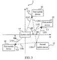
- FIG. 3is a diagram of the wireless communication system 1 in FIG. 1 positioning the first mobile device 10 .
- the system end 14cooperates with the second mobile device 12 to determine the coordinates of each of the first mobile devices 10 .
- a coordinate system 2is established in advance by the system end 14 .
- the system end 14is at the original point of the coordinate system 2 , and the coordinate system 2 has a X axis and a Y axis.
- the system end 14can use TOA algorithm, TDOA algorithm, or RSS algorithm to determine the distances LA 1 -LAn between the system end 14 and each of the first mobile devices 10 .
- DOA algorithmis used to determine the angles ⁇ 1 - ⁇ n corresponding to the X axis or the Y axis for each of the first mobile device 10 .
- the coordinate CB 1 of the second mobile device 12is already known.
- the second mobile device 12can use TOA algorithm, TDOA algorithm, or RSS algorithm to determine the distances LB 1 -LBn between the second mobile device 12 and each of the first mobile devices 10 .
- the system end 14can determine the coordinates C 1 -Cn of each of the first mobile devices 10 on the coordinate system 2 according to the distances LA 1 -LAn between the system end 14 and each of the first mobile devices 10 , the angles ⁇ 1 - ⁇ n, each of which the first mobile device 10 corresponds to the X axis or the Y axis, and the distances LB 1 -LBn between the second mobile device 12 and each of the first mobile devices 10 . By doing that, the coordinates C 1 -Cn of each of the first mobile devices 10 can be obtained.
- the function of the second mobile device 12is to cooperate with the system end 14 for the more accurate positioning of the first mobile device 10 .
- the number of the second mobile device 12can be larger than 1 to increase the efficiency and the accuracy of positioning.
- each of the first mobile devices 10When each of the first mobile devices 10 receives the signal from the system end 14 , each of the first mobile devices 10 would detect the corresponding RSSs. Then, each of the first mobile devices 10 can transmit the corresponding RSS to the system end 14 or the second mobile device 12 . Thus, the system end 14 or the second mobile device 12 can automatically generate the RSS distribution map 3 as shown in FIG. 2 according to the coordinates C 1 -Cn and the corresponding RSSs of each of the first mobile devices 10 .
- FIG. 4is a diagram of the wireless communication system 1 in FIG. 1 , positioning the first mobile device 10 of another preferred embodiment according to the invention.
- the wireless communication system 1has three second mobile devices 12 .
- Each of the second mobile devices 12respectively has at least one wireless positioning algorithm selected from a group consisting of: TOA algorithm, TDOA algorithm, RSS algorithm, and other similar wireless positioning algorithm.
- the coordinates CB 1 -CB 3 of the second mobile devicesare already known.
- the three second mobile devices 12can use TOA algorithm, TDOA algorithm, or RSS algorithm, and cooperate with a triangle positioning algorithm to determine the coordinates C 1 -Cn of the first mobile devices.
- the triangle positioning algorithmcan be easily achieved by those who knows the prior art well. It is not unnecessarily described here. In practical applications, the number of the second mobile devices 12 can be larger than 3 to increase the efficiency and the accuracy of positioning.
- each of the first mobile devices 10When each of the first mobile devices 10 receives the signal from the system end 14 , each of the first mobile devices 10 would detect the first corresponding RSS. Then, each of the first mobile devices 10 can transmit the first corresponding RSS to the system end 14 or the second mobile device 12 . Thus, the system end 14 or the second mobile device 12 can automatically generate the RSS distribution map 3 as shown in FIG. 2 , according to the coordinates C 1 -Cn of the first mobile devices 10 and the RSSs of the first mobile devices 10 .
- the RSS distribution map 3is used for positioning the target mobile device (not shown in the figure).
- the target mobile devicereceives the signals from the system end 14 , the target mobile device will detect the corresponding RSS. Then, the target mobile device can determine the coordinates of the target mobile device according to the RSSs and the RSS distribution map 3 . It should be noticed that when the larger the number of the first mobile device becomes, the more accurate the positioning method using the RSS distribution map 3 is.
- the wireless positioning algorithm of the system end 14 and/or the second mobile device 12can be cooperated to determine the coordinate of the target mobile device more accurately.
- the system end 14 or the second mobile device 12can calculate the RSS corresponding to the X value of the target coordinate and the RSS corresponding to the Y value, respectively, according to the coordinates in the RSS distribution map 3 and the corresponding RSS by using the least squares method. Then, an average RSS is obtained by averaging the RSS corresponding to the X value of the target coordinate and the RSS corresponding to the Y value to be the RSS of the target coordinate.
- the RSS calculated by the least squares methodis replaced by the real RSS.
- the RSS distribution map 3can be updated by the wireless communication system 1 to ensure more accurate positioning, and it will not be affected by the change of the environment.
- the wireless positioning function of the system end 14 and/or the second mobile device 12can be selectively stopped temporarily to save on the electricity cost.
- the second mobile device 12can selectively enable or disable the wireless positioning function of the second mobile device 12 any time according to the integrity of the RSS distribution map 3 in the positioning range of the second mobile device 12 to save on the electricity cost.
- the positioning range of the second mobile device 12depends on the wireless standard used in the second mobile device 12 .
- the positioning range of the UWB and the bluetoothis 10 meters; the positioning range of the 802.11b/g area network is 50-100 meters. It should be noticed that the wireless standard used in the second mobile device 12 is not limited to that.
- FIG. 5Please refer to FIG. 5 .
- a mobile device(not shown in FIG. 5 ) is in a region covered by a plurality of system ends 14 ( FIG. 5 shows only three system ends 14 )
- an RSS distribution map with higher accuracycan be generated according to the invention.
- the connecting ranges of three different system endsare represented by three circles with dotted line.
- the different regions covered by the three system ends 14are represented as A, B, C, D, respectively.
- the three system ends 14are connected with each other by network.
- the mobile devicemoves randomly in the regions A, B, C, or D, it is capable of communicating with each system end 14 respectively.
- the mobile deviceis capable of recording the RSSs of different system ends in the common regions A, B, C, D, and the RSS is the strongest among the regions.
- FIG. 6is a diagram of the RSS distribution map generated by the coordinates, system ends, and RSSs.
- the methodis not limited by the above RSS distribution map corresponding to single system end. That is to say, when a plurality of system ends covers a region jointly, the invention can position the mobile device more accurate. Furthermore, the invention can keep the best connecting state when the mobile device connects to the system end.
- the wireless communication system of the inventionis to use the coordinates of the mobile devices and the RSSs of the mobile devices for automatically generating the RSS distribution map 3 .
- the mobile devicecan promptly determine the coordinate of the mobile device itself by the RSS distribution map. Due to the number of the mobile device becomes larger and larger, the wireless communication system of the invention will be more efficient and cost-effective for establishing the RSS distribution map.
- the wireless communication system of the inventionmakes the positioning more accurate and would not be affected by the change of the environment.
Landscapes
- Engineering & Computer Science (AREA)
- Computer Networks & Wireless Communication (AREA)
- Signal Processing (AREA)
- Position Fixing By Use Of Radio Waves (AREA)
- Mobile Radio Communication Systems (AREA)
- Telephone Function (AREA)
Abstract
Description
Claims (14)
Applications Claiming Priority (3)
| Application Number | Priority Date | Filing Date | Title |
|---|---|---|---|
| TW096108710 | 2007-03-14 | ||
| TW96108710A | 2007-03-14 | ||
| TW096108710ATWI353140B (en) | 2007-03-14 | 2007-03-14 | Wireless communication system for automatically ge |
Publications (2)
| Publication Number | Publication Date |
|---|---|
| US20080227470A1 US20080227470A1 (en) | 2008-09-18 |
| US8103286B2true US8103286B2 (en) | 2012-01-24 |
Family
ID=39763223
Family Applications (1)
| Application Number | Title | Priority Date | Filing Date |
|---|---|---|---|
| US11/907,207Expired - Fee RelatedUS8103286B2 (en) | 2007-03-14 | 2007-10-10 | Wireless communication system for automatically generating a received signal strength distribution map |
Country Status (2)
| Country | Link |
|---|---|
| US (1) | US8103286B2 (en) |
| TW (1) | TWI353140B (en) |
Families Citing this family (5)
| Publication number | Priority date | Publication date | Assignee | Title |
|---|---|---|---|---|
| US8234272B2 (en)* | 2007-05-04 | 2012-07-31 | Sony Mobile Communications Ab | Searching and ranking contacts in contact database |
| US8792387B2 (en) | 2009-03-09 | 2014-07-29 | Sony Corporation | System and method for effectively populating a mesh network model |
| US8692667B2 (en) | 2011-01-19 | 2014-04-08 | Qualcomm Incorporated | Methods and apparatus for distributed learning of parameters of a fingerprint prediction map model |
| US9008695B2 (en) | 2013-01-08 | 2015-04-14 | Qualcomm Incorporated | Method, system and/or device for adjusting expected received signal strength signature values |
| TWI650973B (en)* | 2017-03-30 | 2019-02-11 | 財團法人電信技術中心 | Wireless communication based method for collecting data |
Citations (8)
| Publication number | Priority date | Publication date | Assignee | Title |
|---|---|---|---|---|
| WO2000050919A2 (en) | 1999-02-25 | 2000-08-31 | Microsoft Corporation | Method and computer-readable medium for locating and tracking a user in a wireless network using a table of dignal data |
| US6204812B1 (en)* | 1998-10-09 | 2001-03-20 | Cell-Loc Inc. | Methods and apparatus to position a mobile receiver using downlink signals, part II |
| US6266514B1 (en)* | 1998-11-06 | 2001-07-24 | Telefonaktiebolaget Lm Ericsson | Poor network coverage mapping |
| US6675009B1 (en)* | 2001-02-15 | 2004-01-06 | Sprint Communications Company, L.P. | Automated configuration of a wireless communication device |
| CN1570664A (en) | 2003-04-25 | 2005-01-26 | 微软公司 | Calibration of a device location measurement system that utilizes radio signal strengths |
| TWI237124B (en) | 2002-10-09 | 2005-08-01 | Accton Technology Corp | Wireless positioning method combining time of arrival and angle of arrival |
| CN1672061A (en) | 2002-07-31 | 2005-09-21 | 美商内数位科技公司 | Method and system for locating mobile units based on angular measurements |
| WO2005096568A1 (en) | 2004-03-31 | 2005-10-13 | Koninklijke Philips Electronics, N.V. | Method for positioning of wireless medical devices with short-range radio frequency technology |
- 2007
- 2007-03-14TWTW096108710Apatent/TWI353140B/ennot_activeIP Right Cessation
- 2007-10-10USUS11/907,207patent/US8103286B2/ennot_activeExpired - Fee Related
Patent Citations (8)
| Publication number | Priority date | Publication date | Assignee | Title |
|---|---|---|---|---|
| US6204812B1 (en)* | 1998-10-09 | 2001-03-20 | Cell-Loc Inc. | Methods and apparatus to position a mobile receiver using downlink signals, part II |
| US6266514B1 (en)* | 1998-11-06 | 2001-07-24 | Telefonaktiebolaget Lm Ericsson | Poor network coverage mapping |
| WO2000050919A2 (en) | 1999-02-25 | 2000-08-31 | Microsoft Corporation | Method and computer-readable medium for locating and tracking a user in a wireless network using a table of dignal data |
| US6675009B1 (en)* | 2001-02-15 | 2004-01-06 | Sprint Communications Company, L.P. | Automated configuration of a wireless communication device |
| CN1672061A (en) | 2002-07-31 | 2005-09-21 | 美商内数位科技公司 | Method and system for locating mobile units based on angular measurements |
| TWI237124B (en) | 2002-10-09 | 2005-08-01 | Accton Technology Corp | Wireless positioning method combining time of arrival and angle of arrival |
| CN1570664A (en) | 2003-04-25 | 2005-01-26 | 微软公司 | Calibration of a device location measurement system that utilizes radio signal strengths |
| WO2005096568A1 (en) | 2004-03-31 | 2005-10-13 | Koninklijke Philips Electronics, N.V. | Method for positioning of wireless medical devices with short-range radio frequency technology |
Non-Patent Citations (4)
| Title |
|---|
| English Translation of CN1570664. |
| English Translation of CN1672061. |
| English Translation of Office Action in related Chinese Patent Application. |
| Office Action in related Chinese Patent Application. |
Also Published As
| Publication number | Publication date |
|---|---|
| US20080227470A1 (en) | 2008-09-18 |
| TW200838217A (en) | 2008-09-16 |
| TWI353140B (en) | 2011-11-21 |
Similar Documents
| Publication | Publication Date | Title |
|---|---|---|
| US7174172B2 (en) | System and method for asset location in wireless networks | |
| US6956527B2 (en) | Wireless network access point configuration | |
| US20160033616A1 (en) | Location determination of a mobile device | |
| US20070265775A1 (en) | Dual-mode location position system | |
| CN104735781B (en) | A kind of indoor locating system and its localization method | |
| US8103286B2 (en) | Wireless communication system for automatically generating a received signal strength distribution map | |
| TWI354806B (en) | Local location-tracking system | |
| KR101121907B1 (en) | Real time locating system and method using directional antennas | |
| CN114051201A (en) | Indoor positioning method based on genetic algorithm optimization | |
| US20110244883A1 (en) | Method and mobile radio terminal device to determine position within mobile radio networks by means of direction finding | |
| US20120263050A1 (en) | Wireless network access device with positioning function and method thereof | |
| CN101282573B (en) | Wireless Communication System for Automatically Generating Received Signal Strength Profiles | |
| CN115052339A (en) | Wireless positioning method, system, device, electronic equipment and medium | |
| CN102236804A (en) | Reader-writer | |
| Wang et al. | Adaptive rfid positioning system using signal level matrix | |
| KR20090076236A (en) | Magnetic Position Recognition System and Method for Mobile Robot | |
| CN111918389A (en) | Outdoor positioning method and device based on unmanned aerial vehicle gateway | |
| Arigye et al. | NNT: nearest neighbour trapezoid algorithm for IoT WLAN smart indoor localization leveraging RSSI height estimation | |
| CN115963446A (en) | Positioning method, positioning device, electronic terminal, electronic device and storage medium | |
| KR20180074363A (en) | Method for wireless position estimation in multi-hop system | |
| KR101213171B1 (en) | Apparatus and method for estimating location of moving body | |
| KR20190108373A (en) | Wireless positioning traning system to measure indoor position | |
| Wu et al. | Localization of wireless sensor networks using a moving beacon with a directional antenna | |
| JP7264922B2 (en) | Two-way signal positioning method and its two-way signal positioning system | |
| CN201069880Y (en) | Positioning system for positioning wireless communication device |
Legal Events
| Date | Code | Title | Description |
|---|---|---|---|
| AS | Assignment | Owner name:QUANTA COMPUTER INC., TAIWAN Free format text:ASSIGNMENT OF ASSIGNORS INTEREST;ASSIGNOR:TIEN, KAI-WEN;REEL/FRAME:020011/0929 Effective date:20071001 | |
| ZAAA | Notice of allowance and fees due | Free format text:ORIGINAL CODE: NOA | |
| ZAAB | Notice of allowance mailed | Free format text:ORIGINAL CODE: MN/=. | |
| STCF | Information on status: patent grant | Free format text:PATENTED CASE | |
| FPAY | Fee payment | Year of fee payment:4 | |
| MAFP | Maintenance fee payment | Free format text:PAYMENT OF MAINTENANCE FEE, 8TH YEAR, LARGE ENTITY (ORIGINAL EVENT CODE: M1552); ENTITY STATUS OF PATENT OWNER: LARGE ENTITY Year of fee payment:8 | |
| FEPP | Fee payment procedure | Free format text:MAINTENANCE FEE REMINDER MAILED (ORIGINAL EVENT CODE: REM.); ENTITY STATUS OF PATENT OWNER: LARGE ENTITY | |
| LAPS | Lapse for failure to pay maintenance fees | Free format text:PATENT EXPIRED FOR FAILURE TO PAY MAINTENANCE FEES (ORIGINAL EVENT CODE: EXP.); ENTITY STATUS OF PATENT OWNER: LARGE ENTITY | |
| STCH | Information on status: patent discontinuation | Free format text:PATENT EXPIRED DUE TO NONPAYMENT OF MAINTENANCE FEES UNDER 37 CFR 1.362 | |
| FP | Lapsed due to failure to pay maintenance fee | Effective date:20240124 |