US8103111B2 - Coding method, electronic camera, recording medium storing coded program, and decoding method - Google Patents
Coding method, electronic camera, recording medium storing coded program, and decoding methodDownload PDFInfo
- Publication number
- US8103111B2 US8103111B2US11/963,940US96394007AUS8103111B2US 8103111 B2US8103111 B2US 8103111B2US 96394007 AUS96394007 AUS 96394007AUS 8103111 B2US8103111 B2US 8103111B2
- Authority
- US
- United States
- Prior art keywords
- information
- coding
- image
- data
- processing unit
- Prior art date
- Legal status (The legal status is an assumption and is not a legal conclusion. Google has not performed a legal analysis and makes no representation as to the accuracy of the status listed.)
- Expired - Fee Related, expires
Links
- 238000000034methodMethods0.000titleclaimsabstractdescription100
- 238000012545processingMethods0.000claimsabstractdescription124
- 230000008569processEffects0.000claimsabstractdescription72
- 238000006243chemical reactionMethods0.000claimsdescription15
- 230000003287optical effectEffects0.000claimsdescription10
- 230000006835compressionEffects0.000claimsdescription5
- 238000007906compressionMethods0.000claimsdescription5
- 230000007480spreadingEffects0.000claimsdescription3
- 241000338137Teratosphaeria nubilosaSpecies0.000description27
- 230000000875corresponding effectEffects0.000description19
- 238000010586diagramMethods0.000description19
- 230000006870functionEffects0.000description10
- 230000008901benefitEffects0.000description4
- 230000015572biosynthetic processEffects0.000description4
- 238000012937correctionMethods0.000description4
- 230000003247decreasing effectEffects0.000description4
- 230000004048modificationEffects0.000description3
- 238000012986modificationMethods0.000description3
- 230000002596correlated effectEffects0.000description2
- 239000011159matrix materialSubstances0.000description2
- 238000013139quantizationMethods0.000description2
- 230000006978adaptationEffects0.000description1
- 239000000284extractSubstances0.000description1
- 239000004973liquid crystal related substanceSubstances0.000description1
- 230000007246mechanismEffects0.000description1
- 238000005070samplingMethods0.000description1
- 239000004065semiconductorSubstances0.000description1
- 230000035945sensitivityEffects0.000description1
- 230000001360synchronised effectEffects0.000description1
- 238000012549trainingMethods0.000description1
Images


Classifications
- G—PHYSICS
- G02—OPTICS
- G02B—OPTICAL ELEMENTS, SYSTEMS OR APPARATUS
- G02B30/00—Optical systems or apparatus for producing three-dimensional [3D] effects, e.g. stereoscopic images
- G02B30/20—Optical systems or apparatus for producing three-dimensional [3D] effects, e.g. stereoscopic images by providing first and second parallax images to an observer's left and right eyes
- G02B30/26—Optical systems or apparatus for producing three-dimensional [3D] effects, e.g. stereoscopic images by providing first and second parallax images to an observer's left and right eyes of the autostereoscopic type
- G02B30/27—Optical systems or apparatus for producing three-dimensional [3D] effects, e.g. stereoscopic images by providing first and second parallax images to an observer's left and right eyes of the autostereoscopic type involving lenticular arrays
- H—ELECTRICITY
- H04—ELECTRIC COMMUNICATION TECHNIQUE
- H04N—PICTORIAL COMMUNICATION, e.g. TELEVISION
- H04N19/00—Methods or arrangements for coding, decoding, compressing or decompressing digital video signals
- H04N19/50—Methods or arrangements for coding, decoding, compressing or decompressing digital video signals using predictive coding
- H04N19/597—Methods or arrangements for coding, decoding, compressing or decompressing digital video signals using predictive coding specially adapted for multi-view video sequence encoding
- H—ELECTRICITY
- H04—ELECTRIC COMMUNICATION TECHNIQUE
- H04N—PICTORIAL COMMUNICATION, e.g. TELEVISION
- H04N13/00—Stereoscopic video systems; Multi-view video systems; Details thereof
- H04N13/20—Image signal generators
- H04N13/204—Image signal generators using stereoscopic image cameras
- H04N13/207—Image signal generators using stereoscopic image cameras using a single 2D image sensor
- H04N13/232—Image signal generators using stereoscopic image cameras using a single 2D image sensor using fly-eye lenses, e.g. arrangements of circular lenses
- H—ELECTRICITY
- H04—ELECTRIC COMMUNICATION TECHNIQUE
- H04N—PICTORIAL COMMUNICATION, e.g. TELEVISION
- H04N19/00—Methods or arrangements for coding, decoding, compressing or decompressing digital video signals
- H04N19/60—Methods or arrangements for coding, decoding, compressing or decompressing digital video signals using transform coding
- H—ELECTRICITY
- H04—ELECTRIC COMMUNICATION TECHNIQUE
- H04N—PICTORIAL COMMUNICATION, e.g. TELEVISION
- H04N19/00—Methods or arrangements for coding, decoding, compressing or decompressing digital video signals
- H04N19/90—Methods or arrangements for coding, decoding, compressing or decompressing digital video signals using coding techniques not provided for in groups H04N19/10-H04N19/85, e.g. fractals
- H04N19/93—Run-length coding
- H—ELECTRICITY
- H04—ELECTRIC COMMUNICATION TECHNIQUE
- H04N—PICTORIAL COMMUNICATION, e.g. TELEVISION
- H04N23/00—Cameras or camera modules comprising electronic image sensors; Control thereof
- H04N23/60—Control of cameras or camera modules
- H04N23/63—Control of cameras or camera modules by using electronic viewfinders
- H—ELECTRICITY
- H04—ELECTRIC COMMUNICATION TECHNIQUE
- H04N—PICTORIAL COMMUNICATION, e.g. TELEVISION
- H04N23/00—Cameras or camera modules comprising electronic image sensors; Control thereof
- H04N23/60—Control of cameras or camera modules
- H04N23/67—Focus control based on electronic image sensor signals
Definitions
- the present inventionrelates to a coding method for coding an image taken by a plenoptic camera, an electronic camera, a recording medium storing a coded program, and a decoding method of decoding a coded image.
- FIG. 20shows a focusing function of an ordinary camera.
- Lightis condensed through a focusing lens 21 and other not-shown optical systems (e.g., a zoom optical system), and projected on an image pickup element 27 arranged at an image plane 21 F.
- the position of the focusing lens 21 with respect to the image plane 21 Fis changeable along the optical axis 21 H, as indicated by the arrow 21 B.
- the position of the focusing lens 21is used for processing the firmware of a camera upon control of auto-focus (AF), for example.
- AFauto-focus
- the position of the focusing lens 21is managed by discrete numeric values.
- the reference numeral 21 A in the drawingindicates such a “focus value”.
- the focusing lens 21is composed of a lens group including two or more lenses.
- the focus value 21 A of such cameraindicates the changeable and controllable total conditions of such a lens group.
- a lens of a cameraforms, on a plane, an image of an object that exists on another plane.
- a plane whose image is formed on the image plane 21 F without a blur via the focusing lens 21 arranged at a predetermined focus valueis called “a best object plane”.
- the image of the subjectis formed on the image pickup element 27 in a completely focused state.
- the focus value 21 Athe subject distance 21 E, which is a distance from the image plane 21 F to the best object plane 21 D, can be changed.
- the focus value 21 A and subject distance 21 Ecorrespond one-to-one each other.
- FIG. 19Ashows the case of photographing with such an ordinary camera.
- the focus on a subject Xis adjusted by the operation of auto focus or manual focus. This operation corresponds to adjustment of the best object plane 21 D to the subject plane of a subject X by moving the focusing lens 21 in the direction of the optical axis 21 H.
- FIG. 19Ashows the state that the focusing lens 21 is moved to a certain focus value 21 A, and the best object plane 21 D coincides with the subject plane of the subject X.
- a release buttonis pressed in this state, light from the subject X is projected on the image pickup element 27 through the focusing lens 21 in focus.
- the micro lens array 25is provided on the image plane 21 F in FIG. 19B , and the image pickup element 27 is arranged on a plane behind the image plane 21 F.
- various rays of light K 1 , K 2 and K 3 from the subject X projected on the micro lens array 25are separated by each micro lens 25 A, and projected on a part 27 A of the image pickup element 27 . Therefore, the information formed by the part 27 A of the image pickup element includes the information about the directions of the rays of light.
- the light from the subject Xis projected on the micro lens array 25 . Therefore, the result of image formation by the image pickup element 27 may include position information indicating the position of a subject from which a ray of light is radiated.
- image information(light field image) as a result of the image formation by an image pickup element of a plenoptic camera includes information about rays of light in a space (light ray information). Therefore, a plenoptic camera can perform sampling of four-dimensional light ray information.
- U.S. Pat. No. 6,097,394describes a method of coding light ray information (light field image information).
- the methodadopts vector quantization to increase a decoding speed.
- vector quantized datais decoded by referring to an index in a codebook and outputting it, unlike the predictive coding adopted in a Moving Picture Experts Group (MPEG) system.
- MPEGMoving Picture Experts Group
- a method of coding light ray informationincluding information about a position on a predetermined plane and information about an incident angle to the plane when a ray of light from a subject enters the plane, comprising: dividing the light ray information into two or more processing unit blocks; executing a first coding process to obtain first block unit information composing first image information about the subject by coding each of the processing unit blocks; and executing a second coding process to obtain second block unit information composing second image information different types from the first image information by coding each of the processing unit blocks.
- a method of coding light ray informationthat is pixel data arranged in two dimensions obtained by receiving a ray of light from a subject by an image pickup element and includes information about a position on a predetermined plane and information about an incident angle when a ray of light from a subject enters the plane, comprising: dividing the light ray information into two or more two-dimensional blocks including two or more the pixel data and information about an angle of the ray of light spreading in a different direction from the subject; obtaining two or more processing unit blocks, wherein each of two or more processing unit blocks comprises of two or more two-dimensional blocks; executing a first coding process to obtain first block unit information composing first image information about the subject by coding each of the processing unit blocks; and executing a second coding process to obtain second block unit information composing second image information different types from the first image information by coding each of the processing unit blocks.
- an electronic cameracomprising: a focusing lens; a micro lens array which is arranged at a focal position of the focusing lens, and composed of two or more micro lenses; an image pickup element which is composed of two or more pixels arranged in two dimensions to convert a subject image formed by sequentially passing the focusing lens and micro lens array, into an electric signal; a coding unit which codes light ray information corresponding to the result of receiving light by the two or more pixels; wherein the light ray information includes information about a position on a plane of the micro lens array and information about an incident angle to the plane of the micro lens array when a ray of light from the subject enters the plane via the focusing lens and micro lens array, and the coding unit divides the light ray information into two or more processing unit blocks, and executes a first coding process to obtain first block unit information composing first image information about the subject by coding each of the two or more processing unit blocks and a second coding process to obtain second block unit information composing second image
- a computer readable recording mediumstoring a coded program for coding light ray information including information about a position on a predetermined plane and information about an angle incident to the plane when a ray of light from a subject enters the plane, wherein the program causes a computer to execute the following functions: a function for dividing the light ray information into two or more processing unit blocks; a function for executing a first coding process to obtain first block unit information composing first image information about the subject by coding each of the two or more processing unit blocks, for each of the processing unit blocks; and a function for executing a second coding process to obtain second block unit information composing second image information different types from the first image information by coding each of the processing unit blocks, for each of the processing unit blocks.
- a method of decoding coded light ray informationincluding information about a position on a predetermined plane and information about an incident angle to the plane when a ray of light from a subject enters the plane, comprising: generating first block unit information composing first decoded image information obtained by decoding first image information about the subject obtained by coding the light ray information for each predetermined processing unit block; and generating second block unit information composing second decoded image information obtained by decoding second image information related to the subject and coded using a coding method different from that of the first image information, for the each predetermined processing unit block.
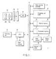
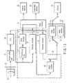
- FIG. 1is a block diagram of a digital camera according to an embodiment of the invention.
- FIG. 2is a diagram for explaining the relationship between a micro lens and a pixel of an image pickup unit shown in FIG. 1 ;
- FIG. 3is diagram for explaining a micro lens block
- FIG. 4is a block diagram for explaining some of the functions of a processing unit shown in FIG. 1 ;
- FIG. 5is a flowchart for explaining the processing steps of a pixel data generator shown in FIG. 4 ;
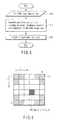
- FIG. 6is a diagram for explaining a micro lens block in an embodiment of the invention.
- FIG. 7is a diagram for explaining a processing block in an embodiment of the invention.
- FIG. 8Ais a diagram for explaining a coding method of a micro lens block in an embodiment of the invention.
- FIG. 8Bis a diagram for explaining another coding method of a micro lens block in an embodiment of the invention.
- FIG. 9is a diagram for explaining a zigzag scanning adopted in a coding method according to an embodiment of the invention.
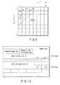
- FIG. 10is a diagram for explaining a recording format of image data coded in an embodiment of the invention.
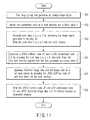
- FIG. 11is a flowchart for explaining the process of coding image data and writing the data into a work memory according to the result of image formation by the image pickup unit shown in FIG. 1 ;
- FIG. 12is a diagram for explaining the flow of data in the process shown in FIG. 11 ;
- FIG. 13is a flowchart for explaining the processes in the step S 24 shown in FIG. 11 ;
- FIG. 14is a flowchart for explaining a method of coding a thumbnail image in an embodiment of the invention.
- FIG. 15is a flowchart for explaining a reproducing process in an embodiment of the invention.
- FIG. 16is a diagram for explaining the flow of data in the reproducing process shown in FIG. 15 ;
- FIG. 17is a flowchart for explaining a process of displaying a live view image in an embodiment of the invention.
- FIG. 18is a diagram for explaining a modification of the coding process in an embodiment of the invention.
- FIG. 19Ais diagram for explaining the principle of image pickup of a conventional camera
- FIG. 19Bis a diagram for explaining the principle of image pickup of a plenoptic camera.
- FIG. 20is a diagram for explaining the principle of image pickup of an ordinary camera.
- FIG. 1is a block diagram of a digital camera 1 according to an embodiment of the invention.
- the digital camera 1has an operating unit 22 , an optical system 23 , a micro lens array 25 , an image pickup unit 27 , an analog front-end (AFE) 29 , a work memory 31 , a processing unit 32 , a memory interface 33 , an internal memory 35 , a memory interface 37 , a detachable memory 39 , a video memory 41 , a display 43 , an external interface 45 , a flash memory 47 , and a CPU 48 , for example.
- AFEanalog front-end
- the AFE 29 , work memory 31 , processing unit 32 , memory interface 33 , memory interface 37 , video memory 41 , external interface 45 , and CPU 48are electrically connected through a signal cable 21 .
- the operating unit 22outputs an operating signal corresponding to the user's operation, to the CPU 48 .
- the operating unit 22includes various operating members, such as a power supply button to turn on the power supply of the digital camera 1 , and a release button to execute photographing of a still picture.
- the optical system 23includes a focusing lens 23 a and a zoom lens 23 b , condenses the light from a subject, and emits it to the micro lens array 25 .
- the focusing lens 23 aprojects the light from points of a subject on one convergence point on the micro lens array 25 .
- the micro lens array 25comprises two or more micro lenses ML (s, t) arranged like an s ⁇ t matrix, as shown in FIG. 2 and FIG. 3 .
- Each micro lensseparates the light (a converged light beam) emitted from each of the points of the subject, according to the direction (angle) of each of the light emitted from those points, and projects each of the separated light on a corresponding pixel on the surface of the image pickup element of the image pickup unit 27 .
- the two-dimensional form of each micro lens composing the micro lens array 25is the same as the two-dimensional form of the focusing lens 23 a .
- the two-dimensional formis a rectangle, for example.
- the number of (wasted) pixels not to accept effective light, among 6 ⁇ 6 pixels composing a micro lens block MLB (s, t)can be reduced.
- the image pickup unit 27is a CCD sensor or a CMOS sensor, and is located on the opposite side of the optical system 23 with respect to the micro lens array 25 .
- the image pickup unit 27may be either a one-panel type or three-panel type.
- the image pickup element of the image pickup unit 27has a light-receiving surface composed of two or more pixels arranged as a matrix.
- the shape of the light-receiving surface of each pixelis rectangular, for example.
- the shapes of the focusing lens 23 a , each of the micro lenses, and the light-receiving surface of the image pickup elementare the same, rectangular. Therefore, of the light incident from the focusing lens 23 a , the ratio of the light not received by a pixel of the image pickup unit 27 can be decreased, and the light-receiving sensitivity of the image pickup unit 27 can be increased.
- the pixels composing the image pickup unit 27are handled as a unit of 6 ⁇ 6 pixels micro lens block MLB.
- a micro lens block MLB (s, t)is correlated to one micro lens ML (s, t), for example.
- a micro lens block MLB (s, t)is not necessarily correlated one-to-one to one micro lens ML (s, t), and may be generated by pixel interpolation, etc.
- a 6 ⁇ 6 pixel PIC(u, v) is assigned to each micro lens block MLB (s, t), as shown in FIG. 3 .
- the image pickup unit 27generates an analog RAW image signal corresponding to the electric charge generated by photoelectrical conversion of the light received by each pixel.
- the processing unit 32performs interpolation based on digital RAW image data obtained from a RAW image signal, and generates pixel data L (u, v, s, t) of a pixel PIC (u, v) of each micro lens block MLB (s, t).
- pixel data L (u, v, s, t) with 6 ⁇ 6 pixels of each micro lens block MLB (s, t)has light ray information.
- light ray informationis information about rays of light.
- general light ray informationmay be regarded as 4-dimensional light ray information.
- the light ray information mentioned hereis information including information about a position of a point where a ray of light crosses a predetermined 2-dimensional manifold and an angle incident to the manifold.
- the predetermined manifold mentioned hereis imaginary and optional.
- the predetermined manifoldis a plane or a spherical plane.
- the manifoldmay not be a single thing, and may be composed of two different planes.
- light ray informationmay not be 4-dimensional, and may be 3-dimensional by considering only a vector in one direction on a plane and the angle (1-dimensional) formed by the vector and its ray of light, among the position (2-dimensional) of a point where a ray of light crosses a predetermined plane and the angle (2-dimensional) incident to the plane.
- light ray informationmay be described as information about two locations where two predetermined planes, i.e., first and second planes, cross each other. Such a method is described in U.S. Pat. No. 6,097,394, for example.
- the plane of the micro lens array 25may be considered to be a predetermined plane.
- a position on the planemay be assumed to be expressed by the coordinates (s, t), and an incident angle to the plane may be expressed by the coordinates (u, v).
- the AFE 29executes predetermined analog front-end processing on an analog image signal input from the image pickup unit 27 . Further, the AFE 29 coverts the obtained image signal to a digital signal, and writes the A/D converted digital RAW image data into the work memory 31 .
- the work memory 31temporarily stores data before or after processing by the processing unit 32 .
- the work memory 31is a synchronous DRAM (SDRAM), for example.
- SDRAMsynchronous DRAM
- the processing unit 32encodes and decodes image data obtained by photographing, as described later.
- the processing unit 32is a digital signal processor (DSP), for example. The operation of the processing unit 32 will be explained later in detail.
- the processing unit 32is an example of a coding unit.
- the internal memory 35is a semiconductor memory, such as a flash memory, for example, and is incorporated in being fixed in the digital camera 1 .
- the internal memory 35stores data of an image obtained by photographing, and inputs/outputs the image data to/from the signal cable 21 through the memory interface 33 .
- the detachable memory 39is a memory card comprising a flash memory, for example, and is detachably incorporated in the digital camera 1 .
- the detachable memory 39stores data of an image obtained by photographing, and inputs/outputs the image data to/from the signal cable 21 through the memory interface 37 .
- the video memory 41temporarily stores image data for display generated by the processing unit 32 .
- the display 43displays an image corresponding to the image data stored in the video memory 41 .
- the display 43is a liquid crystal display, for example.
- the external interface 45inputs/outputs data to/from external equipment of the digital camera 1 .
- the external interface 45is a universal serial bus (USB interface), for example.
- the flash memory 47stores various programs to execute photographing, and parameters to execute various processing.
- the CPU 48executes a program read from the flash memory 47 , and totally controls the operations of the digital camera 1 .
- FIG. 4is a block diagram for explaining some of the functions of the processing unit 32 shown in FIG. 1 .
- the processing unit 32has a pixel data generator 50 , thinning-out unit 51 , a joint photographic experts group (JPEG) encoder 53 , a plenoptic encoder 55 , a header adder 61 , a header interpreter 63 , a JPEG decoder 65 , and a plenoptic decoder 67 , as function blocks.
- JPEGjoint photographic experts group
- Some of the hardwarei.e., pixel data generator 50 , thinning-out unit 51 , JPEG encoder 53 , plenoptic encoder 55 , header adder 61 , header interpreter 63 , JPEG decoder 65 , and plenoptic decoder 67 need not be configured as a DSP, and may be configured as an exclusive hardware circuit. Some or all of these functions may be realized by a processor other than a DSP.
- the processes of the processing unit 32are largely divided into generation of pixel data L (u, v, s, t), coding of pixel data L (u, v, s, t), decoding of the coded pixel data L (u, v, s, t), and display of an image corresponding to the decoded pixel data.
- FIG. 5is a flowchart for explaining the processing steps of the pixel data generator 50 .
- Step S 11
- the pixel data generator 50reads RAW image data from the work memory 31 , for example.
- Step S 12
- the pixel data generator 50executes de-mosaic, misalliance correction and interpolation, on the read RAW image data.
- the de-mosaicis a process to complete color information by collecting insufficient color information from surrounding pixels, and giving such information to each pixel upon photographing, and to create a full-color image.
- each pixelhas only single-color information, and requires de-mosaic.
- de-mosaicis unnecessary.
- Misalliance correctionis a process to correct lateral misalliance between the arrangement of a micro lens ML (s, t) of the micro lens array 25 shown in FIG. 3 and the arrangement of a micro lens block MLB of the image pickup unit 27 , by rotating the image indicated by the RAW image data, for example. Interpolation is performed to enable each micro lens block MLB to include a predetermined number of pixel data, for example.
- Step S 13
- the pixel data generator 50writes the pixel data L (u, v, s, t) of one frame generated in the step S 12 , into the work memory 31 , as an image data to be encoded TE.
- the pixel data L (u, v, s, t)is an example of light ray information.
- the thinning-out unit 51generates image data TE 2 by thinning out the pixel data L (u, v, s, t) of a pixel PCI (u, v) other than a pixel PIC (u 0 , v 0 ) that is a pixel PIC ( 4 , 4 ) in each micro lens block MLB, among the pixel data L (u, v, s, t) composing the image data to be encoded TE, as shown in FIG. 6 .
- the image data TE 2becomes data including pixel data L (u 0 , v 0 , s, t), as shown in FIG. 7 .
- the JPEG encoder 53executes JPEG coding on the image data TE 2 generated by the thinning-out unit 51 , and generates a JPEG Huffman code JF.
- the JPEG Huffman code JFis an example of first image information
- the coding by the JPEG encoder 53is an example of a first coding process.
- the JPEG codingis illustrated as an example of the first coding process, but another type of spatial frequency conversation may be used.
- the JPEG encoder 53subjects the image data TE 2 to DCT conversion, and generates a DCT conversion coefficient K.
- the JPEG encoder 53quantizes the DCT conversion coefficient K.
- the JPEG encoder 53scans the quantized DCT conversion coefficient in a zigzag fashion, from a low frequency component (DC) to a high frequency component.
- the JPEG encoder 53subjects the scanned DCT conversion coefficient to an entropy coding such as a Huffman coding, and generates a JPEG Huffman code JF.
- the plenoptic coding unit 55has a path scanner 57 , and a LZW processor 59 , as shown in FIG. 4 .
- the JPEG encoder 53encodes the image data TE 2 including the pixel data L (u 0 , v 0 , s, t).
- the plenoptic encoder 55generates a word string data WORD by lossless coding pixel data L (u, v, s, t) other than the pixel data L (u 0 , v 0 , s, t) in the image data to be encoded TE.
- the path scanner 57scans pixel data L (u, v, s, t) of a pixel PIC (u, v) other than the pixel PIC (u 0 , v 0 ), along five paths: PATH 1 , PATH 2 , PATH 3 , PATH 4 and PATH 5 , taking the pixel PIC (u 0 , v 0 ) in each micro lens block MLB as a starting point, as shown in FIG. 8A .
- the path scanner 57in scanning the PATH 1 , the path scanner 57 generates difference data D ( 5 , 4 , s, t) between pixel data L ( 5 , 4 , s, t) and pixel data L (u 0 , v 0 , S, t), difference data D ( 5 , 3 , s, t) between pixel data L ( 5 , 3 , s, t) and pixel data L ( 5 , 4 , s, t), difference data D ( 6 , 3 , s, t) between pixel data L ( 6 , 3 , s, t) and pixel data L ( 5 , 3 , s, t), and difference data D ( 6 , 4 , s, t) between pixel data L ( 6 , 4 , s, t) and pixel data L ( 6 , 3 , s, t).
- the path scanner 57generates a word, WORD 1 including the difference data D ( 5 , 4 , s, t), D ( 5 , 3 , s, t), D ( 6 , 3 , s, t) and D ( 6 , 4 , s, t).
- the path scanner 57generates difference data D ( 4 , 3 , s, t) between pixel data L ( 4 , 3 , s, t) and pixel data L (u 0 , v 0 , s, t), difference data D ( 4 , 2 , s, t) between pixel data L ( 4 , 2 , s, t) and pixel data L ( 4 , 3 , s, t), difference data D ( 5 , 2 , s, t) between pixel data L ( 5 , 2 , s, t) and pixel data L ( 4 , 2 , s, t), difference data D ( 4 , 1 , s, t) between pixel data L ( 4 , 1 , s, t) and pixel data L ( 5 , 2 , s, t), and difference data D ( 3 , 1 , s, t) between pixel data L ( 3 , s, t) between
- the path scanner 57generates a word, WORD 2 including the difference data D ( 4 , 3 , s, t), D ( 4 , 2 , s, t), D ( 5 , 2 , s, t), D ( 4 , 1 , s, t), and D ( 3 , 1 , s, t).
- the path scanner 57generates difference data D ( 3 , 3 , s, t) between pixel data L ( 3 , 3 , s, t) and pixel data L (u 0 , v 0 , s, t), difference data D ( 3 , 2 , s, t) between pixel data L ( 3 , 2 , s, t) and pixel data L ( 3 , 3 , s, t), difference data D ( 2 , 2 , s, t) between pixel data L ( 2 , 2 , s, t) and pixel data L ( 3 , 2 , s, t), difference data D ( 2 , 3 , s, t) between pixel data L ( 2 , 3 , s, t) and pixel data L ( 2 , 2 s, t), and difference data D ( 1 , 3 , s, t) between pixel data L ( 1 , 3 , s, t) between
- the path scannergenerates a word, WORD 3 including the difference data D ( 3 , 3 , s, t), D ( 3 , 2 , s, t) D ( 2 , 2 , s, t), D ( 2 , 3 , s, t), and D ( 1 , 3 , s, t).
- the path scanner 57generates difference data D ( 3 , 4 , s, t) between pixel data L ( 3 , 4 , s, t) and pixel data L (u 0 , v 0 , s, t), difference data D ( 2 , 5 , s, t) between pixel data L ( 2 , 5 , s, t) and pixel data L ( 3 , 4 , s, t), difference data D ( 2 , 4 , s, t) between pixel data L ( 2 , 4 , s, t), and pixel data L ( 2 , 5 , s, t), difference data D ( 1 , 4 , s, t) between pixel data L ( 1 , 4 , s, t) and pixel data L ( 2 , 4 , s, t).
- the path scannergenerates a word, WORD 4 including the difference data D ( 3 , 4 , s, t), D ( 2 , 5 , s, t) D ( 2 , 4 , s, t), and D ( 1 , 4 , s, t).
- the path scanner 57generates difference data D ( 4 , 5 , s, t) between pixel data L ( 4 , 5 , s, t) and pixel data L (u 0 , v 0 , s, t), difference data D ( 3 , 5 , s, t) between pixel data L ( 3 , 5 , s, t) and pixel data L ( 4 , 5 , s, t), difference data D ( 3 , 6 , s, t) between pixel data L ( 3 , 6 , s, t) and pixel data L ( 3 , 5 , s, t), difference data D ( 4 , 6 , s, t) between pixel data L ( 4 , 6 , s, t) and pixel data L ( 3 , 6 , s, t), and difference data D ( 5 , 5 , s, t) between pixel data L ( 5 , s, t), and difference
- the path scanner 57generates a word, WORD 5 including the difference data D ( 4 , 5 , s, t), D ( 3 , 5 , s, t), D ( 3 , 6 , s, t), D ( 4 , 6 , s, t), and D ( 5 , 5 , s, t).
- the above scanningis not performed for the pixel data L ( 1 , 1 , s, t), L ( 1 , 2 , s, t), L ( 2 , 1 , s, t), L ( 5 , 1 , s, t), L ( 6 , 1 , s, t) L ( 6 , 2 , s, t), L ( 1 , 5 , s, t), L ( 1 , 6 , s, t), L ( 2 , 6 , s, t), L ( 5 , 6 , s, t), L ( 6 , 5 , s, t), and L ( 6 , 6 , s, t) of the pixel PIC (u, v) at four corners in each micro lens block MLB, as shown in FIG.
- the reason why effective pixel data is not obtained in the pixels at four corners in each micro lens block MLBis that the focusing lens 23 a is shaped round, and a blurred circular image is projected on a micro lens block MLB through the focusing lens 23 a . If the focusing lens 23 a and zoom lens 23 b are shaped square, data of pixels other than each one pixel at four corners in the micro lens ML becomes effective, for example, as shown in FIG. 8B . In this case, the path scanner 57 may scan along paths PATH 11 -PATH 14 shown in FIG. 8B .
- the path scanner 57generates a word string data WORD by scanning the pixel data L (u, v, s, t) in each processing block data PRBK in the image data to be encoded TE shown in FIG. 7 , for example, as described above.
- the processing block data PRBKis an example of a processing unit block.
- the micro lens block MLBis an example of two-dimensional block data.
- the path scanner 57generates a word string data WORD by sequentially arranging the words WORD 1 - 5 generated for 64 (8 ⁇ 8) micro lens blocks MLB in a processing block data PRBK, for example, by zigzag scanning, as shown in FIG. 9 .
- the LZW processor 59compresses the word string data WORD input from the path scanner 57 to a LZW code, and generates a LZW compressed code LZ.
- the LZW processor 59may perform a universal coding (LZ coding) on the basis of a dictionary other than LZW.
- the word string data WORDis an example of second image information
- the coding by the plenoptic encoder 55is an example of a second coding process.
- the header adder 61generates a header data HEADER of the JPEG Huffman code JF generated by the JPEG encoder 53 and the LZW compressed code LZ generated by the LZW processor 59 .
- a pointer indicating the position of the LZW compressed code LZ, thumbnail image data, a file size, an image size, date/time of photographing, and other tag informationare written.
- the processing unit 32writes the header data HEADER generated by the header adder 61 , pointer LZP to LZW compressed code LZ, JPEG thumbnail data THM, and JPEG Huffman code JF, into the internal memory 35 and detachable memory 39 in a file format with a data structure shown in FIG. 10 .
- the header interpreter 63interprets the header data HEADER of the JPEG Huffman code JF and LZW compressed code LZ read from the work memory 31 .
- the header interpreter 63reads the pointer LZP to the LZW compressed code LZ, and holds it.
- the header interpreter 63accesses the LZW compressed code LZ as a reading object, based on the pointer LZP, when reading the LZW compressed code LZ later. Further, the header interpreter 63 outputs the JPEG Huffman code read from the work memory 31 to the JPEG decoder 65 , and outputs the LZW compressed code LZ to the plenoptic decoder 67 .
- the JPEG decoder 65decodes the JPEG Huffman code JF, and generates JPEG decoded image data.
- the JPEG decoded image dataincluding the pixel data L (u 0 , v 0 , s, t).
- the decoding by the JPEG decoder 65corresponds to the encoding by the JPEG encoder 53 described before. Namely, the JPEG decoder 65 sequentially executes Huffman decoding, reverse quantizing and reverse DCT, on the JPEG Huffman code JF.
- the plenoptic decoder 67decodes the LZW compressed code LZ, based on the JPEG decoded image data, and generates pixel data L (u, v, s, t) other than the pixel data L (u 0 , v 0 , s, t).
- the decoding by the plenoptic decoder 67corresponds to the encoding by the plenoptic encoder 55 described before, for example.
- FIG. 11is a flowchart for explaining the process of coding image data and writing the data into the work memory 31 , according to the result of image formation by the image pickup unit 27 .
- FIG. 12is a diagram for explaining the flow of data in the process shown in FIG. 11 .
- FIG. 11Each step shown in FIG. 11 will be explained hereinafter by referring to FIG. 12 .
- the order of executing some of the steps shown belowis optional. Some steps may be executed in parallel.
- Step S 21
- the image pickup unit 27receives light from a subject by each pixel, photoelectrically converts the light received by each pixel, and generates an analog RAW image signal corresponding to the electric charge generated by the photoelectric conversion.
- Step S 22
- the processing unit 32obtains the lens parameter and focus value f used in the optical system 23 .
- the focus value fcorresponds one-to-one to the subject distance 21 E in FIG. 19B . Therefore, it is possible to calculate and obtain a value of the subject distance corresponding to the focus value f, instead of the focus value f.
- the subject distance calculated in this waywill also be indicated by f. In a fixed-focal distance camera, it is unnecessary to obtain a focus value. However, for reproduction, it is allowable to obtain a value f of a Hyper-focal distance specific to a camera as a focus value.
- Step S 23
- the AFE 29executes predetermined analog front-end processing on the analog image signal input from the image pickup unit 27 , and writes the digital RAW image data obtained by A/D conversion of the processed image signal into the work memory 31 .
- the pixel data generator 50reads the RAW image data from the work memory 31 , executes de-mosaic, misalliance correction and interpolation, etc. of the image data, and generates pixel data L (u, v, s, t). Then, the pixel data generator 50 writes an image data to be encoded TE including pixel data L (u, v, s, t) into the work memory 31 for each frame.
- Step S 24
- the processing unit 32reads the image data to be encoded TE from the work memory 31 , encodes the data, and generates a JPEG Huffman code JF and a LZW compressed code LZ. Then, the processing unit 32 writes them into the work memory 31 , together with the lens parameter and focus value f obtained in the step S 22 .
- the coding and other processesare executed in the thinning-out unit 51 , JPEG encoder 53 , plenoptic coding unit 55 , and header adder 61 shown in FIG. 4 .
- the process in the step S 24will be described later in detail by referring to FIG. 13 .
- Step S 25
- the header interpreter 63reads the JPEG Huffman code JF from the work memory 31 , interprets the header data HEADER, and decodes the JPEG Huffman code JF by sending it to the JPEG decoder 65 .
- the pixel data L (u 0 , v 0 , s, t)is generated by this process.
- the processing unit 32generates thumbnail image data and quick view displaying image, based on the decoded pixel data L (u 0 , v 0 , s, t).
- the processing unit 32writes the quick view displaying image and thumbnail image data obtained by coding the thumbnail image data to JPEG data, into the work memory 31 .
- the processing unit 32when a thumbnail display instruction is received, the processing unit 32 generates thumbnail image data by decoding the coded thumbnail image data, and writes it into the video memory 41 .
- the thumbnail imageis displayed on the display 43 by this process.
- the thumbnail image dataare image data for displaying an index image including two or more thumbnail images on the display 43 , when an index display instruction is received.
- Step S 26
- the processing unit 32reads the JPEG Huffman code JF, LZW compressed code LZ and thumbnail JPEG image written into the work memory 31 , from the work memory 31 , and writes them into the internal memory 35 or detachable memory 39 .
- FIG. 13is a flowchart for explaining the processes in the step S 24 shown in FIG. 11 in detail.
- the processes in steps S 35 -S 37 (JPEG encoding) and processes in steps S 38 and S 39 (LZW encoding) shown in FIG. 13may be executed in parallel.
- Step S 31
- information for specifying a pixel PIC (u 0 , v 0 ) used to generate a JPEG Huffman code JFis input.
- the information for specifying the pixel PIC (u 0 , v 0 )is previously stored in a predetermined memory, for example.
- Step S 32
- the processing unit 32assigns an initial value “0” to a variable PBC.
- the value indicated by the variable PBCspecifies processing block data PRBK to be encoded shown in FIG. 7 .
- Step S 33
- the processing unit 32increments the value set in the variable PBC by only “1”.
- Step S 34
- the processing unit 32reads the pixel data L (u, v, s, t) in a processing block data PRBK, which is a coding object corresponding to the value indicated by the variable PBC, from the work memory 31 .
- Step S 35
- the thinning-out unit 51extracts the pixel data L (u 0 , v 0 , s, t) of the pixel data L (u, v, s, t) in the processing block data PEBK read in the step S 34 , and generates the image data TE 2 , based on the information input in the step S 31 .
- the JPEG encoder 53executes DCT conversion on the image data TE 2 , and generates a DCT conversion coefficient K (i, j).
- Step S 36
- the JPEG encoder 53quantizes the DCT conversion coefficient K (i, j) generated in the step S 35 .
- Step S 37
- the JPEG encoder 53scans the DCT conversion coefficient quantized in the step S 36 , in a zigzag form from a low frequency component (DC) to a high frequency component. Then, the JPEG encoder 53 executes entropy coding such as Huffman coding on the scanned DCT conversion coefficient, and generates a JPEG Huffman code JF 1 .
- Step S 38
- the path scanner 57 in the plenoptic encoder 55scans the pixel data of pixel PIC (u, v) other than the pixel PIC (u 0 , v 0 ), with respect to the pixel data L (u, v, s, t) in a processing block data PRBK to be encoded, along five paths of PATH 1 , PATH 2 , PATH 3 , PATH 4 and PATH 5 , taking the pixel PIC (n 0 , v 0 ) in each micro lens block MLB as a starting point, as shown in FIG. 8A .
- the path scanner 57generates difference data D (u, v, s, t) different from the immediately previous pixel data L (u, v, s, t), with respect the pixel data L (u, v, s, t) on the path, as described before.
- the path scanner 57generates a word including difference data D (u, v, s, t).
- the path scanner 57generates a word string data WORD by sequentially arranging the words WORD 1 - 5 generated for 64 (8 ⁇ 8) micro lens blocks MLB in a processing block data PRBK, for example, by zigzag scanning, as shown in FIG. 9 .
- Step S 39
- the LZW processor 59executes LZW compression on the word string data WORD input from the path scanner 57 , and generates a LZW compressed code LZ 1 .
- Step S 40
- the header adder 61generates a header data HEADER of the JPEG Huffman code JF generated by the JPEG encoder 53 and the LZW compressed code LZ generated by the LZ processor 59 , and writes it into the work memory 31 by correlating these codes with the header data.
- Step S 41
- the processing unit 32judges whether the process is completed for all processing data PRBKs in the image data to be encoded TE, and terminates the processes in the step S 24 , when the process is completed. Contrarily, when the process is not completed for all processing data PRBKs in the image data to be encoded TE, the process returns to the step S 33 .
- the processing unit 32writes the JPEG Huffman code JF (JF 1 , JF 2 , . . . ) and LZW compressed code LZ (LZ 1 , LZ 2 , . . . ) generated for each processing block data PRBK, into a JPEG Huffman code storing area and LZW compressed code storing area having a data structure shown in FIG. 10 .
- FIG. 14is a flowchart for explaining a process of coding a thumbnail image executed by the processing unit 32 .
- Step S 51
- the processing unit 32information for specifying a pixel PIC (u 0 , v 0 ) used to generate thumbnail image data is input.
- Step S 52
- the processing unit 32reads the pixel data L (u 0 , v 0 , s, t) among the pixel data L (u, v, s, t) composing the image data to be encoded TE stored in the work memory 31 , based on the information input in the step S 51 .
- Step S 53
- the processing unit 32thins out the pixel data L (u 0 , v 0 , s, t) read in the step S 52 , and generates thumbnail image data to be encoded.
- Step S 54
- the processing unit 32executes JPEG encoding on the thumbnail image data to be encoded generated in the step S 53 .
- Step S 55
- the processing unit 32writes the encoded thumbnail image data generated in the step S 54 , into the work memory 31 .
- FIG. 15is a flowchart for explaining a reproducing process. Each step shown in FIG. 15 will be explained by referring to FIG. 16 .
- Step 61
- the processing unit 32reads thumbnail image data (JPEG image data) from the internal memory 35 or detachable memory 39 shown in FIG. 1 , for example, decodes the read thumbnail image data, and writes the decoded data into the video memory 41 . Therefore, a thumbnail image is displayed on the display 43 .
- the JPEG encoded thumbnail image dataincluding pixel data (u 0 , v 0 , s, t) obtained after the thinning-out process upon encoding.
- Step S 62
- the processing unit 32judges whether one of the thumbnail images displayed on the display 43 is selected according to the user's operation of the operating unit and the process goes to the step S 63 , when one of the images is selected.
- Step S 63
- the processing unit 32reads the JPEG Huffman code JF and LZW compressed code LZ of the image corresponding to the thumbnail image selected in the step S 62 , from the internal memory 35 or detachable memory 39 , and writes the read codes into the work memory 31 .
- the JPEG decoder 65 in the processing unit 32reads the JPEG Huffman code JF corresponding to the thumbnail image selected in the step S 62 , from the work memory 31 , decodes it, and generates JPEG decoded image data.
- the JPEG decoded image dataincluding pixel data L (u 0 , v 0 , s, t).
- the processing unit 32writes the JPEG decoded image data into the video memory 41 , and displays an image on the display 43 based on the JPEG decoded image data.
- the processing unit 32writes the JPEG decoded image data into the work memory 31 .
- Step S 64
- the JPEG decoder 65generates pixel data L (u, v, s, t) other than the pixel data L (u 0 , v 0 , s, t) of the selected image, based on the JPEG decoded image data generated in the step S 63 and the LZW compressed code LZ corresponding to the thumbnail image selected in the step S 62 , and writes it into the work memory 31 .
- the processing unit 32generates image data of a focus value f based on the pixel data L (u, v, s, t), writes it into the video memory 41 , and displays a corresponding image on the display 43 .
- Step S 65
- the JPEG decoder 65generates image data corresponding to a focus value discretely adjacent to the focus value f that is read by correlating to an image, by using the decoded pixel data L (u, v, s, t), and writes the generated image data into the work memory 31 .
- the generation of the image datais performed based on the method disclosed in the aforementioned “Light Field Photography with a Hand-held Plenoptic Camera”, Ren Ng et al, Stanford Tech Report CTSR 2005-2002, 2005, for example.
- Step S 66
- the processing unit 32displays an image corresponding to the new focus value on the display 43 , and generates image data corresponding to a focus value adjacent to the new focus value, based on the pixel data L (u, v, s, t), and writes it into the work memory 31 .
- the JPEG decoder 65erases the image data corresponding to a focus value not adjacent to the newly selected focus value, from the work memory 31 .
- FIG. 17is a flowchart for explaining a process of displaying a live view image on the display 43 shown in FIG. 1 .
- Step S 71
- the image pickup unit 27generates an analog RAW image signal corresponding to the electric charge generated by photoelectric conversion of the light received by each pixel.
- Step S 72
- the AFE 29executes predetermined analog front-end processing on an analog image signal input from the image pickup unit 27 , and writes the processed digital RAW image data into the work memory 31 .
- the pixel data generator 50reads the RAW image data from the work memory 31 , and generates pixel data L (u, v, s, t) by executing de-mosaic, misalliance correction, and interpolation for the read RAW image data. Then, the pixel data generator 50 writes the image data to be encoded TE including the pixel data L (u, v, s, t) for one frame into the work memory 31 .
- Step S 73
- the processing unit 32reads the pixel data L (u 0 , v 0 , s, t) among the pixel data L (u, v, s, t) written into the work memory 31 in the step S 72 .
- Step S 74
- the processing unit 32generates live view image data based on the pixel data L (u 0 , v 0 , s, t) read in the step S 73 , and writes the generated live view image data into the video memory 41 . By this process, a live view image is displayed on the display 43 .
- an image data to be encoded including 4-dimensional light ray informationis encoded, taking a processing block data PRBK as a unit, as explained by using FIG. 7 and FIG. 13 .
- the load of the processing unit 32 caused by the codingcan be reduced.
- a chip with a relative low processing capacitycan be used, and a storage capacity demanded of the work memory 31 can be decreased.
- the pixel data L (u 0 , v 0 , s, t) in the micro lens block MLBis encoded to JPEG data together with other pixel data L (u 0 , v 0 , s, t) in the same processing block data PRBK.
- pixel data L (u, v, s, t) other than the pixel data L (u 0 , v 0 , s, t) in the micro lens block MLBis also encoded to LZW data together with pixel data L (u, v, s, t) other than the pixel data L (u 0 , v 0 , s, t) in the other micro lens blocks MLB in the same processing block data PRBK.
- processing of 8 ⁇ 8 blocks in the JPEG processingis executed in parallel with LZW compression of a processing block PRBK.
- a processing load caused by codingcan be decreased compared with spatial coding of all pixel data. This facilitates adaptation to a portable plenoptic camera. Further, the encoding speed is increased by executing the processing of 8 ⁇ 8 blocks in JPEG processing and LZW compression of a processing block PRBK in parallel in each processing block PRBK. Further, in the digital camera 1 , pixel data L (u, v, s, t) other than the pixel data L (u 0 , v 0 , s, t) is encoded (lossless encoded) to LZW data in a micro lens block MLB, and light ray information can be coded with high quality without losing the amount of information. Namely, information about the direction of propagation of a light ray is losslessly coded, and necessary information is recorded without loss upon refocusing to various focus values. Therefore, a refocused image is very clear.
- thumbnail image datais generated by thinning out the pixel data L (u 0 , v 0 , s, t) composing the image data to be encoded TE, and the generated image data is encoded, as shown in FIG. 14 . Therefore, thumbnail image data can be generated with a relatively small processing load.
- a live view imageis displayed on the display 43 by writing pixel data L (u, v, s, t) into the work memory 31 upon photographing, and writing an image resized from the image obtained by reading the pixel data (u 0 , v 0 , s, t) from the work memory 31 , into the video memory 41 , as shown in FIG. 17 .
- difference data D (u, v, s, t)between adjacent pixel data L (u, v, s, t) has been illustrated.
- a method of generating difference data D (u, v, s, t)is optional.
- itis allowed to generate difference data between one pixel data and two or more pixel data, and to encode that difference data.
- the number of pixels composing a micro lens block MLB indicated in this embodiment, and the number of micro lens block MLBs composing a processing block data PRBKare just an example, and they may be freely set.
- a case of forming an image on a pixel of the image pickup unit 27 by passing a light ray from a subject through the micro lens array 25has been illustrated.
- a method of forming an imageis not limited, as long as light enters a pixel just like including light ray information. It is allowed to form an image on a pixel of the image pickup unit 27 by reflecting a light ray from a subject by using a reflector.
Landscapes
- Engineering & Computer Science (AREA)
- Multimedia (AREA)
- Signal Processing (AREA)
- Physics & Mathematics (AREA)
- General Physics & Mathematics (AREA)
- Optics & Photonics (AREA)
- Studio Devices (AREA)
- Compression Or Coding Systems Of Tv Signals (AREA)
- Compression Of Band Width Or Redundancy In Fax (AREA)
- Transforming Light Signals Into Electric Signals (AREA)
Abstract
Description
Claims (11)
Applications Claiming Priority (2)
| Application Number | Priority Date | Filing Date | Title |
|---|---|---|---|
| JP2006350717 | 2006-12-26 | ||
| JP2006-350717 | 2006-12-26 |
Publications (2)
| Publication Number | Publication Date |
|---|---|
| US20080152215A1 US20080152215A1 (en) | 2008-06-26 |
| US8103111B2true US8103111B2 (en) | 2012-01-24 |
Family
ID=39542891
Family Applications (1)
| Application Number | Title | Priority Date | Filing Date |
|---|---|---|---|
| US11/963,940Expired - Fee RelatedUS8103111B2 (en) | 2006-12-26 | 2007-12-24 | Coding method, electronic camera, recording medium storing coded program, and decoding method |
Country Status (3)
| Country | Link |
|---|---|
| US (1) | US8103111B2 (en) |
| JP (1) | JP5142701B2 (en) |
| CN (1) | CN101212566B (en) |
Cited By (6)
| Publication number | Priority date | Publication date | Assignee | Title |
|---|---|---|---|---|
| US20100194917A1 (en)* | 2009-02-03 | 2010-08-05 | Kenji Funamoto | Imaging apparatus and live-view image display method thereof |
| US20120045118A1 (en)* | 2007-09-07 | 2012-02-23 | Microsoft Corporation | Image resizing for web-based image search |
| US8941750B2 (en) | 2011-12-27 | 2015-01-27 | Casio Computer Co., Ltd. | Image processing device for generating reconstruction image, image generating method, and storage medium |
| US20150312593A1 (en)* | 2014-04-24 | 2015-10-29 | Lytro, Inc. | Compression of light field images |
| US20160212443A1 (en)* | 2014-04-24 | 2016-07-21 | Lytro, Inc. | Predictive light field compression |
| US20160241855A1 (en)* | 2015-02-16 | 2016-08-18 | Canon Kabushiki Kaisha | Optimized plenoptic image encoding |
Families Citing this family (161)
| Publication number | Priority date | Publication date | Assignee | Title |
|---|---|---|---|---|
| US7620309B2 (en)* | 2006-04-04 | 2009-11-17 | Adobe Systems, Incorporated | Plenoptic camera |
| US8559705B2 (en) | 2006-12-01 | 2013-10-15 | Lytro, Inc. | Interactive refocusing of electronic images |
| US10298834B2 (en) | 2006-12-01 | 2019-05-21 | Google Llc | Video refocusing |
| US20100265385A1 (en)* | 2009-04-18 | 2010-10-21 | Knight Timothy J | Light Field Camera Image, File and Configuration Data, and Methods of Using, Storing and Communicating Same |
| US8290358B1 (en)* | 2007-06-25 | 2012-10-16 | Adobe Systems Incorporated | Methods and apparatus for light-field imaging |
| US8019215B2 (en)* | 2007-08-06 | 2011-09-13 | Adobe Systems Incorporated | Method and apparatus for radiance capture by multiplexing in the frequency domain |
| US7956924B2 (en)* | 2007-10-18 | 2011-06-07 | Adobe Systems Incorporated | Fast computational camera based on two arrays of lenses |
| US7962033B2 (en)* | 2008-01-23 | 2011-06-14 | Adobe Systems Incorporated | Methods and apparatus for full-resolution light-field capture and rendering |
| US8189065B2 (en)* | 2008-01-23 | 2012-05-29 | Adobe Systems Incorporated | Methods and apparatus for full-resolution light-field capture and rendering |
| US8155456B2 (en)* | 2008-04-29 | 2012-04-10 | Adobe Systems Incorporated | Method and apparatus for block-based compression of light-field images |
| DK3876510T3 (en) | 2008-05-20 | 2024-11-11 | Adeia Imaging Llc | CAPTURE AND PROCESSING OF IMAGES USING MONOLITHIC CAMERA ARRAY WITH HETEROGENEOUS IMAGES |
| US11792538B2 (en) | 2008-05-20 | 2023-10-17 | Adeia Imaging Llc | Capturing and processing of images including occlusions focused on an image sensor by a lens stack array |
| US8866920B2 (en) | 2008-05-20 | 2014-10-21 | Pelican Imaging Corporation | Capturing and processing of images using monolithic camera array with heterogeneous imagers |
| US8244058B1 (en) | 2008-05-30 | 2012-08-14 | Adobe Systems Incorporated | Method and apparatus for managing artifacts in frequency domain processing of light-field images |
| JP5169499B2 (en)* | 2008-06-02 | 2013-03-27 | 株式会社ニコン | Imaging device and imaging apparatus |
| JP4538766B2 (en)* | 2008-08-21 | 2010-09-08 | ソニー株式会社 | Imaging device, display device, and image processing device |
| JP5224046B2 (en)* | 2008-09-08 | 2013-07-03 | ソニー株式会社 | Image processing apparatus, imaging apparatus, and display apparatus |
| KR101441586B1 (en)* | 2008-10-06 | 2014-09-23 | 삼성전자 주식회사 | Apparatus and method for capturing image |
| AU2008246243B2 (en)* | 2008-11-19 | 2011-12-22 | Canon Kabushiki Kaisha | DVC as generic file format for plenoptic camera |
| US8279325B2 (en) | 2008-11-25 | 2012-10-02 | Lytro, Inc. | System and method for acquiring, editing, generating and outputting video data |
| US8289440B2 (en) | 2008-12-08 | 2012-10-16 | Lytro, Inc. | Light field data acquisition devices, and methods of using and manufacturing same |
| US8189089B1 (en) | 2009-01-20 | 2012-05-29 | Adobe Systems Incorporated | Methods and apparatus for reducing plenoptic camera artifacts |
| US8315476B1 (en) | 2009-01-20 | 2012-11-20 | Adobe Systems Incorporated | Super-resolution with the focused plenoptic camera |
| JP4706882B2 (en) | 2009-02-05 | 2011-06-22 | ソニー株式会社 | Imaging device |
| US8908058B2 (en)* | 2009-04-18 | 2014-12-09 | Lytro, Inc. | Storage and transmission of pictures including multiple frames |
| US8253712B2 (en)* | 2009-05-01 | 2012-08-28 | Sony Ericsson Mobile Communications Ab | Methods of operating electronic devices including touch sensitive interfaces using force/deflection sensing and related devices and computer program products |
| US8228417B1 (en) | 2009-07-15 | 2012-07-24 | Adobe Systems Incorporated | Focused plenoptic camera employing different apertures or filtering at different microlenses |
| US8345144B1 (en) | 2009-07-15 | 2013-01-01 | Adobe Systems Incorporated | Methods and apparatus for rich image capture with focused plenoptic cameras |
| EP2502115A4 (en) | 2009-11-20 | 2013-11-06 | Pelican Imaging Corp | CAPTURE AND IMAGE PROCESSING USING A MONOLITHIC CAMERAS NETWORK EQUIPPED WITH HETEROGENEOUS IMAGERS |
| US8558915B2 (en)* | 2009-12-22 | 2013-10-15 | Samsung Electronics Co., Ltd. | Photographing apparatus and method |
| JP5490514B2 (en)* | 2009-12-22 | 2014-05-14 | 三星電子株式会社 | Imaging apparatus and imaging method |
| US8749620B1 (en) | 2010-02-20 | 2014-06-10 | Lytro, Inc. | 3D light field cameras, images and files, and methods of using, operating, processing and viewing same |
| US8817015B2 (en) | 2010-03-03 | 2014-08-26 | Adobe Systems Incorporated | Methods, apparatus, and computer-readable storage media for depth-based rendering of focused plenoptic camera data |
| US8928793B2 (en) | 2010-05-12 | 2015-01-06 | Pelican Imaging Corporation | Imager array interfaces |
| US8358366B1 (en) | 2010-05-28 | 2013-01-22 | Adobe Systems Incorporate | Methods and apparatus for high-speed digital imaging |
| US8602893B2 (en)* | 2010-06-02 | 2013-12-10 | Sony Computer Entertainment Inc. | Input for computer device using pattern-based computer vision |
| US8749694B2 (en) | 2010-08-27 | 2014-06-10 | Adobe Systems Incorporated | Methods and apparatus for rendering focused plenoptic camera data using super-resolved demosaicing |
| US8724000B2 (en) | 2010-08-27 | 2014-05-13 | Adobe Systems Incorporated | Methods and apparatus for super-resolution in integral photography |
| US8803918B2 (en) | 2010-08-27 | 2014-08-12 | Adobe Systems Incorporated | Methods and apparatus for calibrating focused plenoptic camera data |
| US8665341B2 (en) | 2010-08-27 | 2014-03-04 | Adobe Systems Incorporated | Methods and apparatus for rendering output images with simulated artistic effects from focused plenoptic camera data |
| US8878950B2 (en) | 2010-12-14 | 2014-11-04 | Pelican Imaging Corporation | Systems and methods for synthesizing high resolution images using super-resolution processes |
| JP5906062B2 (en)* | 2010-12-17 | 2016-04-20 | キヤノン株式会社 | Imaging apparatus and control method thereof |
| US8768102B1 (en) | 2011-02-09 | 2014-07-01 | Lytro, Inc. | Downsampling light field images |
| US9197798B2 (en) | 2011-03-25 | 2015-11-24 | Adobe Systems Incorporated | Thin plenoptic cameras using microspheres |
| JP2012205111A (en)* | 2011-03-25 | 2012-10-22 | Casio Comput Co Ltd | Imaging apparatus |
| EP2708019B1 (en)* | 2011-05-11 | 2019-10-16 | FotoNation Limited | Systems and methods for transmitting and receiving array camera image data |
| US8531581B2 (en) | 2011-05-23 | 2013-09-10 | Ricoh Co., Ltd. | Focusing and focus metrics for a plenoptic imaging system |
| US20130265459A1 (en) | 2011-06-28 | 2013-10-10 | Pelican Imaging Corporation | Optical arrangements for use with an array camera |
| US9184199B2 (en) | 2011-08-01 | 2015-11-10 | Lytro, Inc. | Optical assembly including plenoptic microlens array |
| US20130070060A1 (en) | 2011-09-19 | 2013-03-21 | Pelican Imaging Corporation | Systems and methods for determining depth from multiple views of a scene that include aliasing using hypothesized fusion |
| CN104081414B (en) | 2011-09-28 | 2017-08-01 | Fotonation开曼有限公司 | Systems and methods for encoding and decoding light field image files |
| JP2013090059A (en)* | 2011-10-14 | 2013-05-13 | Sony Corp | Image pickup device, image generation system, server, and electronic equipment |
| JP5267708B2 (en)* | 2011-12-27 | 2013-08-21 | カシオ計算機株式会社 | Image processing apparatus, imaging apparatus, image generation method, and program |
| JP5871625B2 (en) | 2012-01-13 | 2016-03-01 | キヤノン株式会社 | IMAGING DEVICE, ITS CONTROL METHOD, AND IMAGING SYSTEM |
| US9137441B2 (en) | 2012-02-16 | 2015-09-15 | Ricoh Co., Ltd. | Spatial reconstruction of plenoptic images |
| EP2817955B1 (en) | 2012-02-21 | 2018-04-11 | FotoNation Cayman Limited | Systems and methods for the manipulation of captured light field image data |
| JP5895587B2 (en)* | 2012-02-24 | 2016-03-30 | カシオ計算機株式会社 | Image recording apparatus, image recording method, image reproducing apparatus, and image reproducing method |
| US8811769B1 (en) | 2012-02-28 | 2014-08-19 | Lytro, Inc. | Extended depth of field and variable center of perspective in light-field processing |
| US8995785B2 (en) | 2012-02-28 | 2015-03-31 | Lytro, Inc. | Light-field processing and analysis, camera control, and user interfaces and interaction on light-field capture devices |
| US8948545B2 (en) | 2012-02-28 | 2015-02-03 | Lytro, Inc. | Compensating for sensor saturation and microlens modulation during light-field image processing |
| US8831377B2 (en) | 2012-02-28 | 2014-09-09 | Lytro, Inc. | Compensating for variation in microlens position during light-field image processing |
| US9420276B2 (en) | 2012-02-28 | 2016-08-16 | Lytro, Inc. | Calibration of light-field camera geometry via robust fitting |
| US9210392B2 (en) | 2012-05-01 | 2015-12-08 | Pelican Imaging Coporation | Camera modules patterned with pi filter groups |
| US10129524B2 (en) | 2012-06-26 | 2018-11-13 | Google Llc | Depth-assigned content for depth-enhanced virtual reality images |
| US9858649B2 (en) | 2015-09-30 | 2018-01-02 | Lytro, Inc. | Depth-based image blurring |
| US9607424B2 (en) | 2012-06-26 | 2017-03-28 | Lytro, Inc. | Depth-assigned content for depth-enhanced pictures |
| JP2015534734A (en) | 2012-06-28 | 2015-12-03 | ペリカン イメージング コーポレイション | System and method for detecting defective camera arrays, optical arrays, and sensors |
| US20140002674A1 (en) | 2012-06-30 | 2014-01-02 | Pelican Imaging Corporation | Systems and Methods for Manufacturing Camera Modules Using Active Alignment of Lens Stack Arrays and Sensors |
| JP6016516B2 (en)* | 2012-08-13 | 2016-10-26 | キヤノン株式会社 | Image processing apparatus, control method therefor, image processing program, and imaging apparatus |
| IL221491A (en)* | 2012-08-15 | 2016-06-30 | Aspect Imaging Ltd | Mri apparatus combined with lightfield camera |
| PL4296963T3 (en) | 2012-08-21 | 2025-04-28 | Adeia Imaging Llc | Method for depth detection in images captured using array cameras |
| WO2014032020A2 (en) | 2012-08-23 | 2014-02-27 | Pelican Imaging Corporation | Feature based high resolution motion estimation from low resolution images captured using an array source |
| US9214013B2 (en) | 2012-09-14 | 2015-12-15 | Pelican Imaging Corporation | Systems and methods for correcting user identified artifacts in light field images |
| JP6071374B2 (en)* | 2012-09-21 | 2017-02-01 | キヤノン株式会社 | Image processing apparatus, image processing method and program, and imaging apparatus including image processing apparatus |
| EP4307659A1 (en) | 2012-09-28 | 2024-01-17 | Adeia Imaging LLC | Generating images from light fields utilizing virtual viewpoints |
| JP2014086968A (en)* | 2012-10-25 | 2014-05-12 | Ricoh Co Ltd | Image processing device, image processing method, and program |
| US8997021B2 (en) | 2012-11-06 | 2015-03-31 | Lytro, Inc. | Parallax and/or three-dimensional effects for thumbnail image displays |
| WO2014078443A1 (en) | 2012-11-13 | 2014-05-22 | Pelican Imaging Corporation | Systems and methods for array camera focal plane control |
| US9001226B1 (en) | 2012-12-04 | 2015-04-07 | Lytro, Inc. | Capturing and relighting images using multiple devices |
| JP6123341B2 (en)* | 2013-02-19 | 2017-05-10 | カシオ計算機株式会社 | Image processing apparatus, imaging apparatus, image processing method, and program |
| US9462164B2 (en) | 2013-02-21 | 2016-10-04 | Pelican Imaging Corporation | Systems and methods for generating compressed light field representation data using captured light fields, array geometry, and parallax information |
| US9374512B2 (en) | 2013-02-24 | 2016-06-21 | Pelican Imaging Corporation | Thin form factor computational array cameras and modular array cameras |
| US9774789B2 (en) | 2013-03-08 | 2017-09-26 | Fotonation Cayman Limited | Systems and methods for high dynamic range imaging using array cameras |
| US8866912B2 (en) | 2013-03-10 | 2014-10-21 | Pelican Imaging Corporation | System and methods for calibration of an array camera using a single captured image |
| US9124831B2 (en) | 2013-03-13 | 2015-09-01 | Pelican Imaging Corporation | System and methods for calibration of an array camera |
| WO2014165244A1 (en) | 2013-03-13 | 2014-10-09 | Pelican Imaging Corporation | Systems and methods for synthesizing images from image data captured by an array camera using restricted depth of field depth maps in which depth estimation precision varies |
| US9106784B2 (en) | 2013-03-13 | 2015-08-11 | Pelican Imaging Corporation | Systems and methods for controlling aliasing in images captured by an array camera for use in super-resolution processing |
| US9888194B2 (en) | 2013-03-13 | 2018-02-06 | Fotonation Cayman Limited | Array camera architecture implementing quantum film image sensors |
| US9578259B2 (en) | 2013-03-14 | 2017-02-21 | Fotonation Cayman Limited | Systems and methods for reducing motion blur in images or video in ultra low light with array cameras |
| WO2014153098A1 (en) | 2013-03-14 | 2014-09-25 | Pelican Imaging Corporation | Photmetric normalization in array cameras |
| US10122993B2 (en) | 2013-03-15 | 2018-11-06 | Fotonation Limited | Autofocus system for a conventional camera that uses depth information from an array camera |
| US9633442B2 (en) | 2013-03-15 | 2017-04-25 | Fotonation Cayman Limited | Array cameras including an array camera module augmented with a separate camera |
| WO2014150856A1 (en) | 2013-03-15 | 2014-09-25 | Pelican Imaging Corporation | Array camera implementing quantum dot color filters |
| US9438888B2 (en) | 2013-03-15 | 2016-09-06 | Pelican Imaging Corporation | Systems and methods for stereo imaging with camera arrays |
| US9445003B1 (en) | 2013-03-15 | 2016-09-13 | Pelican Imaging Corporation | Systems and methods for synthesizing high resolution images using image deconvolution based on motion and depth information |
| US9497429B2 (en) | 2013-03-15 | 2016-11-15 | Pelican Imaging Corporation | Extended color processing on pelican array cameras |
| JP6173006B2 (en)* | 2013-04-18 | 2017-08-02 | キヤノン株式会社 | Encoding apparatus, encoding method and program, and imaging apparatus |
| US10334151B2 (en) | 2013-04-22 | 2019-06-25 | Google Llc | Phase detection autofocus using subaperture images |
| US10107747B2 (en)* | 2013-05-31 | 2018-10-23 | Ecole Polytechnique Federale De Lausanne (Epfl) | Method, system and computer program for determining a reflectance distribution function of an object |
| JP2015060068A (en)* | 2013-09-18 | 2015-03-30 | 株式会社東芝 | Imaging lens and solid-state imaging device |
| US9898856B2 (en) | 2013-09-27 | 2018-02-20 | Fotonation Cayman Limited | Systems and methods for depth-assisted perspective distortion correction |
| US9264592B2 (en) | 2013-11-07 | 2016-02-16 | Pelican Imaging Corporation | Array camera modules incorporating independently aligned lens stacks |
| US10119808B2 (en) | 2013-11-18 | 2018-11-06 | Fotonation Limited | Systems and methods for estimating depth from projected texture using camera arrays |
| WO2015081279A1 (en) | 2013-11-26 | 2015-06-04 | Pelican Imaging Corporation | Array camera configurations incorporating multiple constituent array cameras |
| JP6135865B2 (en)* | 2013-12-05 | 2017-05-31 | パナソニックIpマネジメント株式会社 | Imaging system, imaging apparatus, and imaging method |
| US9538075B2 (en) | 2013-12-30 | 2017-01-03 | Indiana University Research And Technology Corporation | Frequency domain processing techniques for plenoptic images |
| US9344690B2 (en)* | 2014-01-24 | 2016-05-17 | Microsoft Technology Licensing, Llc | Image demosaicing |
| US10089740B2 (en) | 2014-03-07 | 2018-10-02 | Fotonation Limited | System and methods for depth regularization and semiautomatic interactive matting using RGB-D images |
| US9247117B2 (en) | 2014-04-07 | 2016-01-26 | Pelican Imaging Corporation | Systems and methods for correcting for warpage of a sensor array in an array camera module by introducing warpage into a focal plane of a lens stack array |
| US9521319B2 (en) | 2014-06-18 | 2016-12-13 | Pelican Imaging Corporation | Array cameras and array camera modules including spectral filters disposed outside of a constituent image sensor |
| EP3164950A1 (en)* | 2014-07-03 | 2017-05-10 | Philips Lighting Holding B.V. | Coded light symbol encoding |
| GB2544946B (en) | 2014-08-31 | 2021-03-10 | Berestka John | Systems and methods for analyzing the eye |
| US9635332B2 (en) | 2014-09-08 | 2017-04-25 | Lytro, Inc. | Saturated pixel recovery in light-field images |
| JP2017531976A (en) | 2014-09-29 | 2017-10-26 | フォトネイション ケイマン リミテッド | System and method for dynamically calibrating an array camera |
| US10444931B2 (en) | 2017-05-09 | 2019-10-15 | Google Llc | Vantage generation and interactive playback |
| US10469873B2 (en) | 2015-04-15 | 2019-11-05 | Google Llc | Encoding and decoding virtual reality video |
| US10419737B2 (en) | 2015-04-15 | 2019-09-17 | Google Llc | Data structures and delivery methods for expediting virtual reality playback |
| US10341632B2 (en) | 2015-04-15 | 2019-07-02 | Google Llc. | Spatial random access enabled video system with a three-dimensional viewing volume |
| US10567464B2 (en) | 2015-04-15 | 2020-02-18 | Google Llc | Video compression with adaptive view-dependent lighting removal |
| US10546424B2 (en) | 2015-04-15 | 2020-01-28 | Google Llc | Layered content delivery for virtual and augmented reality experiences |
| US10275898B1 (en) | 2015-04-15 | 2019-04-30 | Google Llc | Wedge-based light-field video capture |
| US10565734B2 (en) | 2015-04-15 | 2020-02-18 | Google Llc | Video capture, processing, calibration, computational fiber artifact removal, and light-field pipeline |
| US10540818B2 (en) | 2015-04-15 | 2020-01-21 | Google Llc | Stereo image generation and interactive playback |
| US11328446B2 (en) | 2015-04-15 | 2022-05-10 | Google Llc | Combining light-field data with active depth data for depth map generation |
| US10412373B2 (en) | 2015-04-15 | 2019-09-10 | Google Llc | Image capture for virtual reality displays |
| US10440407B2 (en) | 2017-05-09 | 2019-10-08 | Google Llc | Adaptive control for immersive experience delivery |
| US9942474B2 (en) | 2015-04-17 | 2018-04-10 | Fotonation Cayman Limited | Systems and methods for performing high speed video capture and depth estimation using array cameras |
| JP6355595B2 (en)* | 2015-06-02 | 2018-07-11 | キヤノン株式会社 | IMAGING ELEMENT, IMAGING DEVICE, IMAGING ELEMENT CONTROL METHOD, PROGRAM, AND STORAGE MEDIUM |
| EP3104595A1 (en)* | 2015-06-08 | 2016-12-14 | Thomson Licensing | Light field imaging device |
| US9979909B2 (en) | 2015-07-24 | 2018-05-22 | Lytro, Inc. | Automatic lens flare detection and correction for light-field images |
| EP3145168A1 (en) | 2015-09-17 | 2017-03-22 | Thomson Licensing | An apparatus and a method for generating data representing a pixel beam |
| JP6817961B2 (en) | 2015-12-14 | 2021-01-20 | パナソニック インテレクチュアル プロパティ コーポレーション オブ アメリカPanasonic Intellectual Property Corporation of America | 3D data coding method, 3D data decoding method, 3D data coding device and 3D data decoding device |
| US10275892B2 (en) | 2016-06-09 | 2019-04-30 | Google Llc | Multi-view scene segmentation and propagation |
| EP3261347A1 (en)* | 2016-06-22 | 2017-12-27 | Thomson Licensing | A method and a device for encoding a signal representative of a light-field content |
| US10771791B2 (en)* | 2016-08-08 | 2020-09-08 | Mediatek Inc. | View-independent decoding for omnidirectional video |
| WO2018061876A1 (en)* | 2016-09-29 | 2018-04-05 | 株式会社ニコン | Imaging device |
| US10679361B2 (en) | 2016-12-05 | 2020-06-09 | Google Llc | Multi-view rotoscope contour propagation |
| US10110869B2 (en)* | 2017-03-08 | 2018-10-23 | Ricoh Company, Ltd. | Real-time color preview generation for plenoptic imaging systems |
| US10594945B2 (en) | 2017-04-03 | 2020-03-17 | Google Llc | Generating dolly zoom effect using light field image data |
| US10474227B2 (en) | 2017-05-09 | 2019-11-12 | Google Llc | Generation of virtual reality with 6 degrees of freedom from limited viewer data |
| IT201700050848A1 (en)* | 2017-05-10 | 2018-11-10 | Sisvel Tech S R L | METHODS AND APPARATUSES FOR ENCODING AND DECODING DIGITAL LIGHT FIELD IMAGES |
| US10354399B2 (en) | 2017-05-25 | 2019-07-16 | Google Llc | Multi-view back-projection to a light-field |
| US10482618B2 (en) | 2017-08-21 | 2019-11-19 | Fotonation Limited | Systems and methods for hybrid depth regularization |
| US10545215B2 (en) | 2017-09-13 | 2020-01-28 | Google Llc | 4D camera tracking and optical stabilization |
| US10965862B2 (en) | 2018-01-18 | 2021-03-30 | Google Llc | Multi-camera navigation interface |
| US11270110B2 (en) | 2019-09-17 | 2022-03-08 | Boston Polarimetrics, Inc. | Systems and methods for surface modeling using polarization cues |
| WO2021071992A1 (en) | 2019-10-07 | 2021-04-15 | Boston Polarimetrics, Inc. | Systems and methods for augmentation of sensor systems and imaging systems with polarization |
| DE112020005932T5 (en) | 2019-11-30 | 2023-01-05 | Boston Polarimetrics, Inc. | SYSTEMS AND METHODS FOR SEGMENTATION OF TRANSPARENT OBJECTS USING POLARIZATION CHARACTERISTICS |
| EP4081933A4 (en) | 2020-01-29 | 2024-03-20 | Intrinsic Innovation LLC | Systems and methods for characterizing object pose detection and measurement systems |
| US11797863B2 (en) | 2020-01-30 | 2023-10-24 | Intrinsic Innovation Llc | Systems and methods for synthesizing data for training statistical models on different imaging modalities including polarized images |
| US11953700B2 (en) | 2020-05-27 | 2024-04-09 | Intrinsic Innovation Llc | Multi-aperture polarization optical systems using beam splitters |
| US12069227B2 (en) | 2021-03-10 | 2024-08-20 | Intrinsic Innovation Llc | Multi-modal and multi-spectral stereo camera arrays |
| US12020455B2 (en) | 2021-03-10 | 2024-06-25 | Intrinsic Innovation Llc | Systems and methods for high dynamic range image reconstruction |
| US11954886B2 (en) | 2021-04-15 | 2024-04-09 | Intrinsic Innovation Llc | Systems and methods for six-degree of freedom pose estimation of deformable objects |
| US11290658B1 (en) | 2021-04-15 | 2022-03-29 | Boston Polarimetrics, Inc. | Systems and methods for camera exposure control |
| US12067746B2 (en) | 2021-05-07 | 2024-08-20 | Intrinsic Innovation Llc | Systems and methods for using computer vision to pick up small objects |
| US12175741B2 (en) | 2021-06-22 | 2024-12-24 | Intrinsic Innovation Llc | Systems and methods for a vision guided end effector |
| US12340538B2 (en) | 2021-06-25 | 2025-06-24 | Intrinsic Innovation Llc | Systems and methods for generating and using visual datasets for training computer vision models |
| US12172310B2 (en) | 2021-06-29 | 2024-12-24 | Intrinsic Innovation Llc | Systems and methods for picking objects using 3-D geometry and segmentation |
| US11689813B2 (en) | 2021-07-01 | 2023-06-27 | Intrinsic Innovation Llc | Systems and methods for high dynamic range imaging using crossed polarizers |
| US12293535B2 (en) | 2021-08-03 | 2025-05-06 | Intrinsic Innovation Llc | Systems and methods for training pose estimators in computer vision |
Citations (11)
| Publication number | Priority date | Publication date | Assignee | Title |
|---|---|---|---|---|
| US5076687A (en) | 1990-08-28 | 1991-12-31 | Massachusetts Institute Of Technology | Optical ranging apparatus |
| US6009188A (en)* | 1996-02-16 | 1999-12-28 | Microsoft Corporation | Method and system for digital plenoptic imaging |
| US6097394A (en) | 1997-04-28 | 2000-08-01 | Board Of Trustees, Leland Stanford, Jr. University | Method and system for light field rendering |
| US6476805B1 (en)* | 1999-12-23 | 2002-11-05 | Microsoft Corporation | Techniques for spatial displacement estimation and multi-resolution operations on light fields |
| US20040114807A1 (en)* | 2002-12-13 | 2004-06-17 | Dan Lelescu | Statistical representation and coding of light field data |
| US20050244065A1 (en)* | 2004-04-30 | 2005-11-03 | Microsoft Corporation | Adaptive compression of multi-level images |
| US20050265444A1 (en)* | 2004-05-27 | 2005-12-01 | Daeyang Foundation | Moving image encoding/decoding apparatus and method |
| US20070252074A1 (en)* | 2004-10-01 | 2007-11-01 | The Board Of Trustees Of The Leland Stanford Junio | Imaging Arrangements and Methods Therefor |
| US20080131019A1 (en)* | 2006-12-01 | 2008-06-05 | Yi-Ren Ng | Interactive Refocusing of Electronic Images |
| US20080193026A1 (en)* | 2007-02-09 | 2008-08-14 | Kenichi Horie | Decoding method, decoding apparatus, storage medium in which decoding program is stored, and electronic camera |
| US20080266655A1 (en)* | 2005-10-07 | 2008-10-30 | Levoy Marc S | Microscopy Arrangements and Approaches |
Family Cites Families (4)
| Publication number | Priority date | Publication date | Assignee | Title |
|---|---|---|---|---|
| JP2001094982A (en)* | 1999-09-20 | 2001-04-06 | Nippon Telegr & Teleph Corp <Ntt> | Hierarchical image encoding method and apparatus, program recording medium used to implement the method, hierarchical image decoding method and apparatus, and program recording medium used to implement the method |
| JP4133357B2 (en)* | 2003-01-15 | 2008-08-13 | シャープ株式会社 | Image coding apparatus and image coding method |
| US7671321B2 (en)* | 2005-01-18 | 2010-03-02 | Rearden, Llc | Apparatus and method for capturing still images and video using coded lens imaging techniques |
| US20070058874A1 (en)* | 2005-09-14 | 2007-03-15 | Kabushiki Kaisha Toshiba | Image data compressing apparatus and method |
- 2007
- 2007-12-24USUS11/963,940patent/US8103111B2/ennot_activeExpired - Fee Related
- 2007-12-25CNCN2007101605444Apatent/CN101212566B/ennot_activeExpired - Fee Related
- 2007-12-26JPJP2007335324Apatent/JP5142701B2/ennot_activeExpired - Fee Related
Patent Citations (11)
| Publication number | Priority date | Publication date | Assignee | Title |
|---|---|---|---|---|
| US5076687A (en) | 1990-08-28 | 1991-12-31 | Massachusetts Institute Of Technology | Optical ranging apparatus |
| US6009188A (en)* | 1996-02-16 | 1999-12-28 | Microsoft Corporation | Method and system for digital plenoptic imaging |
| US6097394A (en) | 1997-04-28 | 2000-08-01 | Board Of Trustees, Leland Stanford, Jr. University | Method and system for light field rendering |
| US6476805B1 (en)* | 1999-12-23 | 2002-11-05 | Microsoft Corporation | Techniques for spatial displacement estimation and multi-resolution operations on light fields |
| US20040114807A1 (en)* | 2002-12-13 | 2004-06-17 | Dan Lelescu | Statistical representation and coding of light field data |
| US20050244065A1 (en)* | 2004-04-30 | 2005-11-03 | Microsoft Corporation | Adaptive compression of multi-level images |
| US20050265444A1 (en)* | 2004-05-27 | 2005-12-01 | Daeyang Foundation | Moving image encoding/decoding apparatus and method |
| US20070252074A1 (en)* | 2004-10-01 | 2007-11-01 | The Board Of Trustees Of The Leland Stanford Junio | Imaging Arrangements and Methods Therefor |
| US20080266655A1 (en)* | 2005-10-07 | 2008-10-30 | Levoy Marc S | Microscopy Arrangements and Approaches |
| US20080131019A1 (en)* | 2006-12-01 | 2008-06-05 | Yi-Ren Ng | Interactive Refocusing of Electronic Images |
| US20080193026A1 (en)* | 2007-02-09 | 2008-08-14 | Kenichi Horie | Decoding method, decoding apparatus, storage medium in which decoding program is stored, and electronic camera |
Non-Patent Citations (4)
| Title |
|---|
| "Survey of Image-Based Representations and Compression Techniques," Heung-Yeung Shum, et al, IEEE Transactions on Circuits and Systems for Video Technology, vol. 13, No. 11, Nov. 2003, pp. 1020-1037.* |
| Ren Ng, "Fourier Slice Photography," (presented at AMC SIGGRAPH 2005, pp. 735-744 (Jul. 31, 2005-Aug. 4, 2005)). |
| Ren Ng, et al., "Light Field Photography with a Hand-held Plenoptic Camera," Stanford Tech Report CTSR 2005-02. |
| T. Takano, et al., "3-D Space Coding Based on Light Ray Data," Journal of The Institute of Image Information and Television Engineers, vol. 52, No. 1, pp. 1321-1327, 1998 (Japan). |
Cited By (17)
| Publication number | Priority date | Publication date | Assignee | Title |
|---|---|---|---|---|
| US20120045118A1 (en)* | 2007-09-07 | 2012-02-23 | Microsoft Corporation | Image resizing for web-based image search |
| US8270772B2 (en)* | 2007-09-07 | 2012-09-18 | Microsoft Corporation | Image resizing for web-based image search |
| US8368775B2 (en)* | 2009-02-03 | 2013-02-05 | Fujifilm Corporation | Imaging apparatus and live-view image display method thereof |
| US20100194917A1 (en)* | 2009-02-03 | 2010-08-05 | Kenji Funamoto | Imaging apparatus and live-view image display method thereof |
| US9749601B2 (en) | 2011-12-27 | 2017-08-29 | Casio Computer Co., Ltd. | Imaging device, image display method, and storage medium for displaying reconstruction image |
| US8941750B2 (en) | 2011-12-27 | 2015-01-27 | Casio Computer Co., Ltd. | Image processing device for generating reconstruction image, image generating method, and storage medium |
| US20170280136A1 (en)* | 2014-04-24 | 2017-09-28 | Lytro, Inc. | Predictive light-field compression |
| US9414087B2 (en)* | 2014-04-24 | 2016-08-09 | Lytro, Inc. | Compression of light field images |
| US9712820B2 (en)* | 2014-04-24 | 2017-07-18 | Lytro, Inc. | Predictive light field compression |
| US20160212443A1 (en)* | 2014-04-24 | 2016-07-21 | Lytro, Inc. | Predictive light field compression |
| US20150312593A1 (en)* | 2014-04-24 | 2015-10-29 | Lytro, Inc. | Compression of light field images |
| US10038909B2 (en) | 2014-04-24 | 2018-07-31 | Google Llc | Compression of light field images |
| US10531082B2 (en)* | 2014-04-24 | 2020-01-07 | Google Llc | Predictive light-field compression |
| US20160241855A1 (en)* | 2015-02-16 | 2016-08-18 | Canon Kabushiki Kaisha | Optimized plenoptic image encoding |
| GB2535475A (en)* | 2015-02-16 | 2016-08-24 | Canon Kk | Optimized plenoptic image encoding |
| US10003806B2 (en)* | 2015-02-16 | 2018-06-19 | Canon Kabushiki Kaisha | Optimized plenoptic image encoding |
| GB2535475B (en)* | 2015-02-16 | 2019-09-18 | Canon Kk | Optimized plenoptic image encoding |
Also Published As
| Publication number | Publication date |
|---|---|
| JP2008182692A (en) | 2008-08-07 |
| US20080152215A1 (en) | 2008-06-26 |
| JP5142701B2 (en) | 2013-02-13 |
| CN101212566B (en) | 2010-07-28 |
| CN101212566A (en) | 2008-07-02 |
Similar Documents
| Publication | Publication Date | Title |
|---|---|---|
| US8103111B2 (en) | Coding method, electronic camera, recording medium storing coded program, and decoding method | |
| US8103112B2 (en) | Decoding method, decoding apparatus, storage medium in which decoding program is stored, and electronic camera | |
| US7151564B2 (en) | Image recording apparatus and method | |
| US8615140B2 (en) | Compression of image data in accordance with depth information of pixels | |
| US9609192B2 (en) | Image processing apparatus, image processing method and program, and imaging apparatus | |
| US10674110B2 (en) | Image encoding apparatus, and control method thereof | |
| JPWO2019142821A1 (en) | Encoding device, decoding device, coding method, decoding method, coding program, and decoding program | |
| WO2017068022A1 (en) | Method for encoding and method for decoding a light field based image and corresponding devices | |
| US20120050490A1 (en) | Method and system for depth-information based auto-focusing for a monoscopic video camera | |
| CN110999305A (en) | A method for encoding an image view matrix obtained from data acquired from a plenoptic camera | |
| JP2014086968A (en) | Image processing device, image processing method, and program | |
| JP2009194760A (en) | Image coding device, image decoding device, program for coding image, and program for decoding image | |
| CN113658128A (en) | Image blurring degree determining method, data set constructing method and deblurring method | |
| KR101476650B1 (en) | Apparatus and method for processing image data successively photographed in a digital image processor | |
| Monteiro et al. | Light field image coding: objective performance assessment of Lenslet and 4D LF data representations | |
| JP5869839B2 (en) | Image processing apparatus and control method thereof | |
| JP5407651B2 (en) | Image processing apparatus and image processing program | |
| JP5247346B2 (en) | Imaging apparatus, control method and program thereof, image processing apparatus, and image processing method | |
| Corcoran et al. | Consumer imaging i–processing pipeline, focus and exposure | |
| JP4375662B2 (en) | Image processing apparatus, image processing method, program, information recording medium, and imaging apparatus | |
| JP6450288B2 (en) | Image encoding device, image decoding device, image encoding method, and image decoding method | |
| JP2018088600A (en) | Image processing apparatus, image processing method, and program | |
| JP7076983B2 (en) | Coding device, image processing device and image processing method | |
| JP2018182621A (en) | Image pickup apparatus, control method therefor, program and recording medium | |
| JP4458408B2 (en) | Image processing apparatus, image processing method, program, and information recording medium |
Legal Events
| Date | Code | Title | Description |
|---|---|---|---|
| AS | Assignment | Owner name:OLYMPUS IMAGING CORP., JAPAN Free format text:ASSIGNMENT OF ASSIGNORS INTEREST;ASSIGNORS:HORIE, KENICHI;SAKATA, SEIICHIRO;REEL/FRAME:020297/0302 Effective date:20071210 | |
| FEPP | Fee payment procedure | Free format text:PAYOR NUMBER ASSIGNED (ORIGINAL EVENT CODE: ASPN); ENTITY STATUS OF PATENT OWNER: LARGE ENTITY | |
| STCF | Information on status: patent grant | Free format text:PATENTED CASE | |
| FPAY | Fee payment | Year of fee payment:4 | |
| AS | Assignment | Owner name:OLYMPUS CORPORATION, JAPAN Free format text:MERGER;ASSIGNOR:OLYMPUS IMAGING CORP.;REEL/FRAME:036616/0332 Effective date:20150401 | |
| AS | Assignment | Owner name:OLYMPUS CORPORATION, JAPAN Free format text:CHANGE OF ADDRESS;ASSIGNOR:OLYMPUS CORPORATION;REEL/FRAME:039344/0502 Effective date:20160401 | |
| FEPP | Fee payment procedure | Free format text:MAINTENANCE FEE REMINDER MAILED (ORIGINAL EVENT CODE: REM.); ENTITY STATUS OF PATENT OWNER: LARGE ENTITY | |
| LAPS | Lapse for failure to pay maintenance fees | Free format text:PATENT EXPIRED FOR FAILURE TO PAY MAINTENANCE FEES (ORIGINAL EVENT CODE: EXP.); ENTITY STATUS OF PATENT OWNER: LARGE ENTITY | |
| STCH | Information on status: patent discontinuation | Free format text:PATENT EXPIRED DUE TO NONPAYMENT OF MAINTENANCE FEES UNDER 37 CFR 1.362 | |
| FP | Lapsed due to failure to pay maintenance fee | Effective date:20200124 |