US8102779B2 - System and method of detecting and locating intermittent electrical faults in electrical systems - Google Patents
System and method of detecting and locating intermittent electrical faults in electrical systemsDownload PDFInfo
- Publication number
- US8102779B2 US8102779B2US12/262,664US26266408AUS8102779B2US 8102779 B2US8102779 B2US 8102779B2US 26266408 AUS26266408 AUS 26266408AUS 8102779 B2US8102779 B2US 8102779B2
- Authority
- US
- United States
- Prior art keywords
- receiver
- fault
- signals
- electrical
- bits
- Prior art date
- Legal status (The legal status is an assumption and is not a legal conclusion. Google has not performed a legal analysis and makes no representation as to the accuracy of the status listed.)
- Active, expires
Links
- 238000000034methodMethods0.000titleclaimsdescription17
- 238000013459approachMethods0.000description41
- 230000005540biological transmissionEffects0.000description12
- 230000008878couplingEffects0.000description11
- 238000010168coupling processMethods0.000description11
- 238000005859coupling reactionMethods0.000description11
- 238000004891communicationMethods0.000description7
- 238000010586diagramMethods0.000description6
- 230000006378damageEffects0.000description5
- 238000001514detection methodMethods0.000description4
- 238000001914filtrationMethods0.000description4
- 230000008569processEffects0.000description4
- 238000012545processingMethods0.000description4
- 238000002310reflectometryMethods0.000description3
- 208000027418Wounds and injuryDiseases0.000description2
- 239000002828fuel tankSubstances0.000description2
- 230000006870functionEffects0.000description2
- 230000014509gene expressionEffects0.000description2
- 208000014674injuryDiseases0.000description2
- 238000009413insulationMethods0.000description2
- 230000008054signal transmissionEffects0.000description2
- 238000001228spectrumMethods0.000description2
- 230000009471actionEffects0.000description1
- 230000004397blinkingEffects0.000description1
- 239000000872bufferSubstances0.000description1
- 230000003139buffering effectEffects0.000description1
- 239000003990capacitorSubstances0.000description1
- 230000008859changeEffects0.000description1
- 230000007797corrosionEffects0.000description1
- 238000005260corrosionMethods0.000description1
- 230000034994deathEffects0.000description1
- 231100000517deathToxicity0.000description1
- 230000003247decreasing effectEffects0.000description1
- 238000002592echocardiographyMethods0.000description1
- 238000004880explosionMethods0.000description1
- 238000007689inspectionMethods0.000description1
- 239000004973liquid crystal related substanceSubstances0.000description1
- 239000000463materialSubstances0.000description1
- 238000012986modificationMethods0.000description1
- 230000004048modificationEffects0.000description1
- 230000009993protective functionEffects0.000description1
- 230000000246remedial effectEffects0.000description1
- 230000004044responseEffects0.000description1
- 239000000126substanceSubstances0.000description1
- 238000012360testing methodMethods0.000description1
- 230000001052transient effectEffects0.000description1
- 230000000007visual effectEffects0.000description1
- XLYOFNOQVPJJNP-UHFFFAOYSA-NwaterSubstancesOXLYOFNOQVPJJNP-UHFFFAOYSA-N0.000description1
- 238000004804windingMethods0.000description1
Images


Classifications
- H—ELECTRICITY
- H04—ELECTRIC COMMUNICATION TECHNIQUE
- H04L—TRANSMISSION OF DIGITAL INFORMATION, e.g. TELEGRAPHIC COMMUNICATION
- H04L1/00—Arrangements for detecting or preventing errors in the information received
- H04L1/24—Testing correct operation
- H—ELECTRICITY
- H04—ELECTRIC COMMUNICATION TECHNIQUE
- H04L—TRANSMISSION OF DIGITAL INFORMATION, e.g. TELEGRAPHIC COMMUNICATION
- H04L1/00—Arrangements for detecting or preventing errors in the information received
- H04L2001/0092—Error control systems characterised by the topology of the transmission link
- H04L2001/0095—Ring
Definitions
- This applicationrelates to approaches for detecting and/or locating electrical faults in electrical systems or networks.
- Intermittent electrical faultsare physical events that manifest themselves occasionally and in often unpredictable ways within electrical systems or networks. When an intermittent fault occurs in a system, the system may produce erroneous results or could fail.
- a wiremay rub against a neighboring wire and a small electrical arc may be created as a result of the contact.
- a clampmay break through the insulation surrounding the wire and touch the wire creating a fault.
- a wiremay break at the back end of a connector thereby creating a fault.
- corrosionmay create intermittent non-contact between wires and pins within a given system.
- cracks on wires within the systemmay have water dripping on them (or the wires may be in contact with other substances) thereby creating electrical faults.
- Internal coil turn-to-turn insulation in electric machinesmay also fail in systems with electrical coils creating electrical faults.
- intermittent electrical faultscan be severe and, in many instances, can cause substantial damage to the electrical equipment, can result in injury to users, or can even cause the loss of human life. For instance electrical fires may be sparked because of the occurrence of some electrical faults. When the faults occur in aircraft, fuel tank explosions may occur if electrical faults occur near a fuel tank. Even if catastrophic damage or injury does not occur, the operational lifetime of machines or systems may be reduced as the result of the occurrence of intermittent electrical faults.
- One characteristic of intermittent faultsis that they are random and unpredictable. Their recurrence is also unpredictable. However, if an intermittent fault is left undetected and un-repaired, a major, disastrous, and permanent fault might follow that may cause deaths, failures, or destruction.
- Another problem with this techniquewas that it required the transmission of high voltage pulses, which some electrical systems with thin coils (e.g., with short wires or thin windings) could not endure.
- Another time domain reflectometry methodemployed spread-spectrum techniques, but this approach did not solve the above-mentioned problems since high voltage pulse transmission was still required and reflection still occurred on branches of the electrical network.
- Still another problem of the reflectometry approachwas that the location of the device must be close to one end of the electrical system, either the line end or the source end. Otherwise, the injected signal would be reflected from both ends and result in a combined, distorted, and reflected signal. This requirement of locating the device at either end is very difficult to meet since many electrical networks are connected in a complicated format, often in a mesh architecture.
- FIG. 1comprises a block diagram of a fault determination system according to various embodiments of the present invention
- FIG. 2comprises one example of a byte-map for use in a fault determination system according to various embodiments of the present invention
- FIG. 3comprises a block diagram and fault determination table illustrating one approach for fault determination according to various embodiments of the present invention
- FIG. 4comprises a block diagram of a fault determination apparatus according to various embodiments of the present invention.
- FIG. 5comprises a flow chart of one approach for determining faults according to various embodiments of the present invention.
- FIG. 6comprises a flow chart of one approach for determining faults according to various embodiments of the present invention.
- FIG. 7comprises a block diagram and flow chart of one approach for determining electrical faults according to various embodiments of the present invention.
- FIG. 8comprises a block diagram of a transmitter and receiver according to various embodiments of the present invention.
- FIG. 9comprises a block diagram of a transmitter or a receiver according to various embodiments of the present invention.
- the approachesutilize one or more transmitters to send signals (e.g., packets) to one receiver and, based upon the mismatch between the signal sent and the signal received at the receiver due to the distortion in the signal transmission caused by the transient of intermittent fault, to determine the presence and/or location of electrical faults.
- signalse.g., packets
- the approaches described hereinare easy and cost effective to use, do not rely upon the transmission of high voltage signals, can be installed at any location within the electrical network, are an effective detection solution for the unpredictable intermittent event of faults that occur between transmitter and receiver, and are not susceptible to the false fault indications obtained in previous approaches.
- signalsare transmitted from a plurality of transmitters that are positioned in an electrical network.
- the signals transmitted by the transmittersare received at a single receiver positioned within the electrical network.
- the received signalsare analyzed and it is determined from the analysis of the received signals whether a fault has occurred in the electrical network between transmitters and receiver. The location of the fault may also be determined.
- a random pause durationis inserted between successively transmitted signals.
- Each of the plurality of transmittershas an associated unique combination of bits that uniquely identifies the transmitter and the unique combination bits is included in the signals sent to the receiver.
- the receiveranalyzes the received combination of bits and compares the combination of bits to an expected combination of bits (expected to be received from the transmitter) and when there is not a match, determines that an electrical fault exists in the segment of the electrical network between the transmitter and the receiver. The location of the electrical fault may also be determined based upon the analysis.
- each of the plurality of transmittersreceives a command signal from the single receiver.
- Each transmitteronly transmits signals to the single receiver when the command signal has been received at the selected transmitter. The total absence of an expected message from a transmitter or the mismatching of any message received (compared to an expected value) of a message sent in response to the command signal indicates the existence of open circuit or potential faults.
- An electrical interconnect backbone 102is coupled to transmitters 104 , 106 , 108 , 110 , 112 , 114 and 116 via electrical branches 120 , 122 , 124 , 126 , 128 and 130 respectively.
- the electrical interconnect backbone 102is also connected to a receiver 118 .
- the electrical interconnect backbone 102may be any type of electrical connection of any voltage level or any current type, e.g., direct or alternating.
- the backbone 102may include two wires (e.g., one ground and the other a wire transmitting a DC current and voltage).
- Other examples of backbone arrangements and any number of electrical wiresare possible to distribute electrical power.
- electrical sources having voltages of approximately 100 vRMS (or 28V DC)are distributed across the backbone 102 and the branches of the network 100 .
- the transmitters 104 , 106 , 108 , 110 , 112 , 114 and 116are any type of device capable of transmitting any type of modulated communication signal, over electrical circuit 102 without compromising the power delivering function of the electrical network 102 , that includes any type of information.
- the transmitters 104 , 106 , 108 , 110 , 112 , 114 and 116may include controllers to form packets or messages, modems to convert the messages to suitable signals through modulation (e.g., having the proper voltage levels) for transmission, and a coupling network to provide filtering and protective functions to connect any of the transmitters to the electrical interconnect backbone 102 .
- the transmitters 104 , 106 , 108 , 110 , 112 , 114 and 116may operate and transmit packets or messages at any voltage level appropriate for the electrical interconnect backbone 102 .
- the receiver 118is any device capable of receiving modulated communication signals from any of the transmitters 104 , 106 , 108 , 110 , 112 , 114 and 116 via the electrical interconnect backbone 102 .
- the receiver 118may include a controller, a modem and a coupling network.
- the coupling networkbuffers the receiver or transmitter from the electrical interconnect backbone 102 by a filtering function so that the receiver or transmitter insulates it from the high voltages of the electrical network while effectively sending and receiving the modulated signal.
- the modem in the transmittermodulates the digital signal formed by the controller and the modulated signal travels through the coupling network into the electrical network.
- the modem in the receiveraccepts the modulated signal via the coupling network sent from the transmitters, demodulates the signals into a digital byte format, and sends the digital data to its controller.
- the receiver controllerprocesses the signals for data errors or mismatch to determine whether a fault has been detected or the likelihood that a fault has been detected and/or the possible location of faults. Various error rates can be determined from the process.
- the receiver 118communicates with a port 132 and the port 132 is coupled to an external device 134 .
- the external device 134may be a personal computer, display, enunciator or any other type of device that is capable of alerting a user that a fault has been detected somewhere in the network 100 .
- the location of faults and message error rate calculated for the locationmay also be displayed to give the severity (likelihood) or status of the fault progress.
- the external device 134may provide some or all of the fault determination processing capabilities rather than the receiver 118 when the receiver 118 is limited to provide the mismatch or error occurrence only.
- the transmitters 104 , 106 , 108 , 110 , 112 , 114 and 116transmit messages to the receiver 118 .
- the receiver 118analyzes the messages that it receives and based upon the results of the analysis determines whether a fault exists, the likelihood that a fault exists, and/or the possible (or determined) location(s) of faults (e.g., within a particular branch 120 , 122 , 124 , 126 and 128 or 130 of the network 100 ). It will be appreciated that although a single receiver is shown in the example of FIG. 1 , any number of receivers may be used in the network 100 . Additionally, any number of transmitters may be employed in the network 100 .
- remedial actioncan be taken. For example, a user can access the potential site of the error, determine if a problem exists, and, if a problem exists remedy the problem (e.g., replace a wire).
- a message or packet 200includes a preamble byte 202 , a receiver information byte 204 , a transmitter information byte 206 , and 4 to m message bytes 208 where m is an integer greater than 4.
- each transmitter within the systeme.g., transmitters 106 , 108 , 110 , 112 , 114 , or 116 of FIG. 1
- has a uniquely identifiable message bytee.g., some unique pattern of binary ones and zeros
- a transmittere.g., the receiver 118 of FIG. 1
- All information in the message or packet 200is included in the data stream that is transmitted to the receiver.
- the receivercompares the data received from the transmitter against pre-assigned data that it has stored regarding each transmitter. In the case of a mismatch between the received data and the expected data, a fault is potentially detected.
- the non-reception at the receiver of an expected message or packet expected to be sent from the transmittermay also indicate the existence of a fault in the form of open circuit in the network.
- each transmittermonitors the wire via a “carrier detect” approach that detects if there are any modulated signals on the wire, and waits to send its signal until there is no signal on the wire. Therefore, at any one moment, only one transmitter is allowed to send signals.
- multiple transmitterssend signals without the control of the receiver.
- a random pause durationis inserted after each signal transmission.
- Each transmitterhas an equal chance to send a signal to the receiver and, therefore, each wire segment (e.g., each branch of the network) is monitored at the same priority with an equal chance of detecting errors compared with any other electrical branch.
- the receiveris the master of this single-master and multiple-slave protocol.
- the receiversends a message or packet (e.g., a command) to a transmitter, for example, the message of FIG. 2 .
- this messageis copied and sent back to the receiver.
- the comparison of the received message at the receiver against the sent messagedetermines if there is an error in the signal, which in turn indicates that a fault exists in the wire segment between the receiver and the commanded transmitter.
- an erroris detected if no return message is detected by the receiver (e.g., within a predetermined amount of time), indicating possible disconnected, open circuit.
- an electrical backbone 302is coupled to transmitters 304 , 306 and 308 and a receiver 310 .
- the network 300is divided into segments S 1 , S 2 and S 3 and branches Br 1 , Br 2 and Br 3 .
- a table 312is stored in a memory at the receiver and used to determine the possible location or locations of electrical faults within the network 300 . For example, using the techniques described herein, it is determined if a particular error exists in one of the branches associated with a particular transmitter. For example, the mismatch of expected data from the transmitter 304 versus expected data, while there is no mismatch from the transmitters 306 and 308 , may indicate that a fault exists in branch Br 1 .
- the table 312may be any type of data structure and is also not limited to the format shown in FIG. 3 . Moreover, the examples shown in table 312 may vary depending upon the placement of the transmitters and the receiver and the exact configuration of the network or other circumstances.
- the device 400can be configured to operate as either a transmitter or receiver and includes a controller 402 , a modem 404 , a coupling network 406 , and a memory 408 .
- the controller 402may form messages (e.g., packets) to send to a receiver via the modem 404 and coupling network 406 .
- the modem 404forms signals according to appropriate voltage levels or protocols and the coupling network 406 provides appropriate buffering and/or filtering capabilities that protect the modem 404 and controller 402 from electrical hazards (e.g., overvoltage conditions) present on the backbone and, at the same time, effectively inject the modulated signals into the backbone.
- electrical hazardse.g., overvoltage conditions
- the coupling network 406filters in only the modulated signal from the backbone and the modem 404 demodulates the signal into digital data and sends it to the controller 402 .
- the device 400may store in the memory 408 a table as has been described above with respect to FIG. 3 .
- the controller 402then may perform an analysis to determine the potential location or locations of faults within a particular network. Further, the controller 402 may be coupled to a port, which communicates with external devices to indicate to a user the presence and potential locations of faults. Further, the controller 402 , modem 404 , and/or coupling network 406 may be coupled to an external power supply.
- a message or packetis sent from a transmitter.
- the messagemaybe in the format as indicated in FIG. 2 .
- a random pause durationis inserted after the message.
- the receivercompares the received message to the expected message and determines that a fault exists if there is a mismatch. When a mismatch exists, a potential fault may exist in the portion of the network associated with the transmitter that sent the message.
- a transmitterwaits to receive a message from a receiver.
- the transmitterechoes the same message back to the receiver. Then, it waits for another command from the receiver. In the meantime, if the receiver never receives an echoed message back (e.g., after waiting for a predetermined time period) or the message returned to the receiver is in error (as would be indicated by a comparison of the received message with the expected message), then a fault (including open circuit) is indicated to exist.
- a packet 701(having pre-set values) is sent from transmitters 702 , 704 , and 705 to a controller 703 of a receiver, and read through serial communication port 736 of the controller 703 .
- the packet 701includes, for example, preamble byte 732 , and a transmitter identification byte 733 , and a packet number byte 734 , followed by n data bytes 735 , D 1 through Dn.
- Nmay be any integer value.
- n24 and, consequently, 24 bytes of data are used.
- the rate of the data transmission, or bit ratecan become any speed or any modulation scheme suitable for the modem.
- a 2400 bps power line modemis used that provides approximately 130 kHz of Frequency Shift Keying (FSK) modulation.
- FSKFrequency Shift Keying
- other numbers of data bytesmay be used along with other bit rates and other modulation schemes.
- a longer packet with slower bit rate with a modulation schememay have better chance of intermittent fault detection than a shorter packet with higher bit rate with another modulation scheme.
- the controller 703 of the receiverafter detecting the preamble byte 732 , followed by identification byte 733 , then reads the rest of the bytes (step 760 ) one at a time and store the packet into internal memory space 741 .
- the packet 701is stored as a packet 742 and is used for a comparison with an expected (and previously stored) packet 743 .
- the expected packet 743includes the expected values of information for the packet 742 .
- the packet information stored in memorycan be compared against each of the transmitters.
- the controller 703 at step 762reads the stored packets 742 and 743 and makes a bit-by-bit comparison of all n data bytes against the pre-set values of the n data bytes between the packets 742 and 743 .
- the first analysisis to decide which transmitter sent the packet and the subsequent analysis result for packet mismatch is stored and associated with the transmitter. If the two packets are the same, then the result of no error is registered for the transmitter. Then, with for example, the decision table of FIG. 3 , a fault detection and location decision is made and displayed 753 or uploaded to an upper level computer 755 . Then, the next packet sent from a transmitter is read at step 762 .
- the error detailsmay be stored.
- a faulte.g., “1”
- no-faulte.g., “0
- the final decision on fault determination using the tableis made and communicated to one or more of a port 750 (for display on an enunciator 751 ), a communication port 752 (for presentation on a display 753 ) and/or port 754 (for display on a personal computer 755 ).
- a port 750for display on an enunciator 751
- a communication port 752for presentation on a display 753
- port 754for display on a personal computer 755 .
- graphical imagesmaybe formed to be displayed on some or all of the mentioned external devices.
- a pausemay be inserted between transmitted packets.
- the pause between two consecutive packetsin a system using a microcontroller of 8-bits and 20 MHz speed, is about 100 milliseconds.
- the pause timeis selected so as to be sufficient for processing to occur.
- the pause durationmay be selected to allow for the fault determination process to finish and also for error messages to be sent to external devices (e.g., the enunciator 751 , the display 753 , and/or the personal computer 755 ).
- the pause durationcan also include time to allow processing to occur for a given number of packets, for example, 1000 packets.
- the threshold level of the rate of error that initiates the faultcan be any predetermined value or, alternatively, be determined after a run of the system under clean electrical wire status. Further, the threshold can be automatically determined using the error rate by comparing the error rates during actual/normal operating status and those of actual intermittent fault status.
- a test runmay be executed in a staged intermittent fault condition that sets the threshold level for a fault or no-fault boundary, and thus increases the detection probability while at the same time decreasing false alarm and nuisance readings.
- a first error type that can be calculatedis a Net Packet Error Rate (NPER), which is the percentage of packets that contained errors out of the total number of received packets. In the NPER case, the lost packets by the error in identification byte(s) are ignored.
- NPERNet Packet Error Rate
- TPERTotal Packet Error Rate
- a Net Byte Error Rate(NBER) can be calculated.
- the NBERis the percentage of the number of packets received with just 1 data byte error caused by 1 or 2 bit errors in the byte out of the received packets with no error.
- the NBERfocuses, unlike NPER or TPER, on very short disruptions. Very short disruptions in time rooted from an intermittent fault may cause error in a bit or two in a byte data, not across the data bytes.
- TBERTotal Byte Error Rate
- a receiver 801receives packets over electrical wires 810 and 811 that are transmitted by a transmitter 802 . If the electrical wire carries DC current, then one of the wires 810 or 811 can be a ground wire. In the example of FIG. 8 , both the receiver 801 and the transmitter 802 have the same functional structure and includes a power line modem 802 or 804 and a controller 803 or 805 .
- the receiver 801includes additional interface outputs or ports 812 , 813 and 814 .
- the output 813is connected to an indicator/enunciator 807 to send an alarm when an intermittent fault is detected.
- the port 813is used to display the alarm condition on a display 806 (e.g., a liquid crystal display (LCD)) with texts and graphics.
- the output 814is further used to send the alarm condition to a computer system 820 via serial communication port 808 for displaying on a computer screen or for further analysis of the alarm condition data.
- the errors and error rates discussed hereincan be displayed according to any of the display approaches described herein.
- the transmitter 802includes the power line modem 804 and the controller 805 .
- the controller 805is a microcontroller or microprocessor which includes computing code, controls digital logic, and sends bytes of digital data (e.g., packets).
- the computing codemanages the number of packets sent and how often the packets are sent.
- a power line modem 921 in the transmitter 900receives the serially transmitted digital data stream from a controller 903 , converts the digital data to analog data, and modulates the analog data in FSK (Frequency Shift Keying) scheme (in which digital logic 1 is coded to analog signal of a certain frequency and digital logic 0 is to another frequency).
- FSKFrequency Shift Keying
- the modulated signalis amplified by an amplifier 922 and sent through a coupler 923 , which sends the modulated signals and blocks all other signals outside the frequency band, to the electrical wires 910 and 911 .
- the modern 921may be any commercially available modem chip.
- the modem 921may include a filter that band passes only the frequency band used in the particular FSK scheme that is employed.
- the modem 921has four control and data communication lines with the controller 903 . These include RX control 930 for controlling the reception of digital data, TX control 931 for controlling the transmission of digital data, carrier detect (CD) control 932 for indicating to the controller 903 if and when the modem 922 receives a modulated signal from an electrical wire, and RX/TX control 933 for indicating if a digital signal has been received and is to be transmitted.
- RX control 930for controlling the reception of digital data
- TX control 931for controlling the transmission of digital data
- carrier detect (CD) control 932for indicating to the controller 903 if and when the modem 922 receives a modulated signal from an electrical wire
- RX/TX control 933for indicating if a digital signal has been received and is to be transmitted.
- a modulated signalautomatically is transmitted from the modem 921 and amplified by the amplifier circuit 922 .
- the amplified modulated signalthen is presented to the electrical wires via a coupler 923 , which passes the signals of the frequency band and blocks all other signals.
- the coupler 923in one example, is a transformer coil 924 with filtering capacitors 925 and 926 .
- the structure of the receiveris identical (or nearly identical with the receiver having ports to communicate with external devices) with the structure of the transmitter 900 .
- Various transmission protocolsmay be used. For example, a byte of any data can be sent from the receiver to indicate to the transmitter to send data.
- a packetmay be sent to the receiver with various bytes of data. For example, a preamble byte may be included. The next byte is sent to identify the transmitter and the receiver. To take one example, if the identification byte is a preset data value such as a byte data of 10110011, then the receiver checks if the received identification byte is 10110011. If the received identification byte is the same as the preset data, then the receiver is now ready to receive the data stream that follows. One or more bytes can be used for identification purposes.
- the group of data bytes including the preamble, identification, and actual dataform a packet.
- one packetis transmitted from a transmitter and reception of the same one packet made by a receiver.
- the transmittertransmits the same one packet repeatedly, with a pause between two packets, until, for example, a set number of packets are sent (e.g., 956 packets). Then, packet transmission resumes.
- a set number of packetse.g. 956 packets.
- the receiverignores the packet with the contaminated identification byte since the packet is interpreted as not meant to be sent to the receiver. In this case, one packet is lost and a packet error exists.
- approachesare provided to detect the presence and locations of faults within an existing electrical network.
- the approachesutilize one or more transmitters to send signals (e.g., packets) to one more receivers and based upon the signal received at the receiver, to determine the presence and location of electrical faults.
- signalse.g., packets
- the approaches described hereinare easy and cost effective to use, do not rely upon the transmission of high voltage signals, can be implemented at any place within the electrical system, and are not susceptible to false results as have been obtained in previous approaches.
Landscapes
- Engineering & Computer Science (AREA)
- Computer Networks & Wireless Communication (AREA)
- Signal Processing (AREA)
- Monitoring And Testing Of Transmission In General (AREA)
- Small-Scale Networks (AREA)
Abstract
Description
Application entitled “Housing Arrangement for a Fault Determination Apparatus and Method of Installing the Same” naming Charles Kim as inventor and having Ser. No. 12/262,717 and being filed on the same day as the present application, and provisional application No. 60/846,718 entitled “Method of Detecting Intermittent Faults in Electrical Wire by Utilizing Data Communication Error Over Time,” naming Charles Kim as inventor, filed Sep. 24, 2005, the contents of both of which are incorporated herein by reference in their entirety.
This application relates to approaches for detecting and/or locating electrical faults in electrical systems or networks.
Intermittent electrical faults are physical events that manifest themselves occasionally and in often unpredictable ways within electrical systems or networks. When an intermittent fault occurs in a system, the system may produce erroneous results or could fail. To take some specific examples of particular electrical faults that occur in networks, a wire may rub against a neighboring wire and a small electrical arc may be created as a result of the contact. In another example, a clamp may break through the insulation surrounding the wire and touch the wire creating a fault. In yet another example, a wire may break at the back end of a connector thereby creating a fault. In still another example, corrosion may create intermittent non-contact between wires and pins within a given system. In another example, cracks on wires within the system may have water dripping on them (or the wires may be in contact with other substances) thereby creating electrical faults. Internal coil turn-to-turn insulation in electric machines may also fail in systems with electrical coils creating electrical faults.
The consequences of intermittent electrical faults can be severe and, in many instances, can cause substantial damage to the electrical equipment, can result in injury to users, or can even cause the loss of human life. For instance electrical fires may be sparked because of the occurrence of some electrical faults. When the faults occur in aircraft, fuel tank explosions may occur if electrical faults occur near a fuel tank. Even if catastrophic damage or injury does not occur, the operational lifetime of machines or systems may be reduced as the result of the occurrence of intermittent electrical faults. One characteristic of intermittent faults is that they are random and unpredictable. Their recurrence is also unpredictable. However, if an intermittent fault is left undetected and un-repaired, a major, disastrous, and permanent fault might follow that may cause deaths, failures, or destruction.
Previous attempts at identifying electrical faults have relied upon the visual or instrument-aided inspection of electrical systems. However, various disadvantages exist with these previous approaches. For example, the operation of the system frequently had to be suspended to determine if a fault existed thereby causing various problems such as loss of revenue for the owner or operator of the system. Moreover, many locations within existing systems were frequently hard to reach and/or observe thereby severely limiting the effectiveness of these approaches. These previous approaches also proved unable to detect the fault in many cases since the duration of the fault was often short and the system would behave normally as if nothing happened after this short-lived intermittent fault event. Therefore, it was relatively easy for the observer to miss the occurrence of the fault. Additionally, these approaches often relied upon intrusive placement of any equipment used frequently leading to at least some disruption of the existing system.
Other previous approaches relied upon transmitting electromagnetic waves across the network being observed. In one previous example, pulses were transmitted in networks and any reflections were analyzed to determine if a fault existed. More specifically, incident standing waves or impulses were transmitted and then reflected in the network, and then the time between the incident pulse and the reflected pulse was calculated to determine the distance to the location where the pulse was reflected. Different criteria were then used to determine if the reflection was a potential fault. One problem with this technique was that any change in the wire material (e.g., a branch-out in the network) reflected the incident waves resulting in erroneous fault determination. Another problem with this technique was that it required the transmission of high voltage pulses, which some electrical systems with thin coils (e.g., with short wires or thin windings) could not endure. Another time domain reflectometry method employed spread-spectrum techniques, but this approach did not solve the above-mentioned problems since high voltage pulse transmission was still required and reflection still occurred on branches of the electrical network.
Another previous approach transmitted direct-sequence spread-spectrum modulated signals, instead of high voltage signals, and employed signal processing techniques in an attempt to find and locate electrical faults. These approaches, however, still relied on reflectometry that is, sending incident signal and receiving reflected signal and the timing of them for distance calculation. As a result, although this approach may have, under some circumstances, overcome the need to use high voltage incident voltage pulses, it still had the problem of reflection occurring at all points of branching in the network and in the devices that were connected.
Still another problem of the reflectometry approach was that the location of the device must be close to one end of the electrical system, either the line end or the source end. Otherwise, the injected signal would be reflected from both ends and result in a combined, distorted, and reflected signal. This requirement of locating the device at either end is very difficult to meet since many electrical networks are connected in a complicated format, often in a mesh architecture.
Skilled artisans will appreciate that elements in the figures are illustrated for simplicity and clarity and have not necessarily been drawn to scale. For example, the dimensions and/or relative positioning of some of the elements in the figures may be exaggerated relative to other elements to help to improve understanding of various embodiments of the present invention. Also, common but well-understood elements that are useful or necessary in a commercially feasible embodiment are often not depicted in order to facilitate a less obstructed view of these various embodiments of the present invention. It will further be appreciated that certain actions and/or steps may be described or depicted in a particular order of occurrence while those skilled in the art will understand that such specificity with respect to sequence is not actually required. It will also be understood that the terms and expressions used herein have the ordinary meaning as is accorded to such terms and expressions with respect to their corresponding respective areas of inquiry and study except where specific meanings have otherwise been set forth herein.
Approaches are provided to detect the presence and locations of faults within an electrical network. The approaches utilize one or more transmitters to send signals (e.g., packets) to one receiver and, based upon the mismatch between the signal sent and the signal received at the receiver due to the distortion in the signal transmission caused by the transient of intermittent fault, to determine the presence and/or location of electrical faults. The approaches described herein are easy and cost effective to use, do not rely upon the transmission of high voltage signals, can be installed at any location within the electrical network, are an effective detection solution for the unpredictable intermittent event of faults that occur between transmitter and receiver, and are not susceptible to the false fault indications obtained in previous approaches.
In many of these embodiments, signals are transmitted from a plurality of transmitters that are positioned in an electrical network. The signals transmitted by the transmitters are received at a single receiver positioned within the electrical network. At the single receiver, the received signals are analyzed and it is determined from the analysis of the received signals whether a fault has occurred in the electrical network between transmitters and receiver. The location of the fault may also be determined.
In some examples, a random pause duration is inserted between successively transmitted signals. Each of the plurality of transmitters has an associated unique combination of bits that uniquely identifies the transmitter and the unique combination bits is included in the signals sent to the receiver. The receiver analyzes the received combination of bits and compares the combination of bits to an expected combination of bits (expected to be received from the transmitter) and when there is not a match, determines that an electrical fault exists in the segment of the electrical network between the transmitter and the receiver. The location of the electrical fault may also be determined based upon the analysis.
In other examples, each of the plurality of transmitters receives a command signal from the single receiver. Each transmitter only transmits signals to the single receiver when the command signal has been received at the selected transmitter. The total absence of an expected message from a transmitter or the mismatching of any message received (compared to an expected value) of a message sent in response to the command signal indicates the existence of open circuit or potential faults.
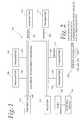
Referring now toFIG. 1 , one example of an approach for determining and detecting electrical faults in anelectrical network 100 is described. Anelectrical interconnect backbone 102 is coupled totransmitters electrical branches electrical interconnect backbone 102 is also connected to areceiver 118. Theelectrical interconnect backbone 102 may be any type of electrical connection of any voltage level or any current type, e.g., direct or alternating. For instance, thebackbone 102 may include two wires (e.g., one ground and the other a wire transmitting a DC current and voltage). Other examples of backbone arrangements and any number of electrical wires are possible to distribute electrical power. In one example, electrical sources having voltages of approximately 100 vRMS (or 28V DC) are distributed across thebackbone 102 and the branches of thenetwork 100.
Thetransmitters electrical circuit 102 without compromising the power delivering function of theelectrical network 102, that includes any type of information. For example, thetransmitters electrical interconnect backbone 102. As mentioned, thetransmitters electrical interconnect backbone 102.
Thereceiver 118 is any device capable of receiving modulated communication signals from any of thetransmitters electrical interconnect backbone 102. As with thetransmitters receiver 118 may include a controller, a modem and a coupling network. As mentioned, the coupling network buffers the receiver or transmitter from theelectrical interconnect backbone 102 by a filtering function so that the receiver or transmitter insulates it from the high voltages of the electrical network while effectively sending and receiving the modulated signal. The modem in the transmitter modulates the digital signal formed by the controller and the modulated signal travels through the coupling network into the electrical network. The modem in the receiver accepts the modulated signal via the coupling network sent from the transmitters, demodulates the signals into a digital byte format, and sends the digital data to its controller. The receiver controller processes the signals for data errors or mismatch to determine whether a fault has been detected or the likelihood that a fault has been detected and/or the possible location of faults. Various error rates can be determined from the process.
Thereceiver 118 communicates with aport 132 and theport 132 is coupled to anexternal device 134. Theexternal device 134 may be a personal computer, display, enunciator or any other type of device that is capable of alerting a user that a fault has been detected somewhere in thenetwork 100. The location of faults and message error rate calculated for the location may also be displayed to give the severity (likelihood) or status of the fault progress. In an alternative approach, theexternal device 134 may provide some or all of the fault determination processing capabilities rather than thereceiver 118 when thereceiver 118 is limited to provide the mismatch or error occurrence only.
In one example of the operation of the system ofFIG. 1 , thetransmitters receiver 118. Thereceiver 118 analyzes the messages that it receives and based upon the results of the analysis determines whether a fault exists, the likelihood that a fault exists, and/or the possible (or determined) location(s) of faults (e.g., within aparticular branch FIG. 1 , any number of receivers may be used in thenetwork 100. Additionally, any number of transmitters may be employed in thenetwork 100.
Once errors are detected and/or their locations determined remedial action can be taken. For example, a user can access the potential site of the error, determine if a problem exists, and, if a problem exists remedy the problem (e.g., replace a wire).
Referring now toFIG. 2 , one example of a message format for messages transmitted according to the approaches described herein is described. A message orpacket 200 includes apreamble byte 202, areceiver information byte 204, atransmitter information byte transmitters FIG. 1 ) has a uniquely identifiable message byte (e.g., some unique pattern of binary ones and zeros) that is known to the receiver and that uniquely identifies a transmitter (e.g., thereceiver 118 ofFIG. 1 ). All information in the message orpacket 200 is included in the data stream that is transmitted to the receiver.
To detect an error or fault, in one approach, the receiver compares the data received from the transmitter against pre-assigned data that it has stored regarding each transmitter. In the case of a mismatch between the received data and the expected data, a fault is potentially detected. The non-reception at the receiver of an expected message or packet expected to be sent from the transmitter may also indicate the existence of a fault in the form of open circuit in the network.
For transmissions across the network, various approaches may be used to ensure signal integrity (e.g., to ensure signals sent by multiple transmitters do not interfere with each other). In any approach used, the modem of each transmitter monitors the wire via a “carrier detect” approach that detects if there are any modulated signals on the wire, and waits to send its signal until there is no signal on the wire. Therefore, at any one moment, only one transmitter is allowed to send signals. In one approach, multiple transmitters send signals without the control of the receiver. To ensure signal integrity, a random pause duration is inserted after each signal transmission. Each transmitter has an equal chance to send a signal to the receiver and, therefore, each wire segment (e.g., each branch of the network) is monitored at the same priority with an equal chance of detecting errors compared with any other electrical branch.
In another approach that may be used to achieve signal arbitration, only a transmitter that is ordered by the receiver is allowed to send a signal. In other words, the receiver is the master of this single-master and multiple-slave protocol. The receiver sends a message or packet (e.g., a command) to a transmitter, for example, the message ofFIG. 2 . After the transmitter receives the message or packet from the receiver, this message is copied and sent back to the receiver. The comparison of the received message at the receiver against the sent message determines if there is an error in the signal, which in turn indicates that a fault exists in the wire segment between the receiver and the commanded transmitter. In some approaches and as described elsewhere herein, an error is detected if no return message is detected by the receiver (e.g., within a predetermined amount of time), indicating possible disconnected, open circuit.
Referring now toFIG. 3 , one example of using these approaches to detect an error or fault in anetwork 300 is described. In this example, anelectrical backbone 302 is coupled totransmitters receiver 310. Thenetwork 300 is divided into segments S1, S2 and S3 and branches Br1, Br2 and Br3.
A table312 is stored in a memory at the receiver and used to determine the possible location or locations of electrical faults within thenetwork 300. For example, using the techniques described herein, it is determined if a particular error exists in one of the branches associated with a particular transmitter. For example, the mismatch of expected data from thetransmitter 304 versus expected data, while there is no mismatch from thetransmitters
To take a few examples and utilizing the table312, if no errors are determined fortransmitters transmitters transmitter 306 then a fault may exist at segment S2 and/or both branches Br2 and Br3. It will be appreciated that the table312 maybe any type of data structure and is also not limited to the format shown inFIG. 3 . Moreover, the examples shown in table312 may vary depending upon the placement of the transmitters and the receiver and the exact configuration of the network or other circumstances.
Referring now toFIG. 4 , one example of a transmitter orreceiver 400 is described. Thedevice 400 can be configured to operate as either a transmitter or receiver and includes acontroller 402, amodem 404, acoupling network 406, and amemory 408.
If used as a transmitter, thecontroller 402 may form messages (e.g., packets) to send to a receiver via themodem 404 andcoupling network 406. Themodem 404 forms signals according to appropriate voltage levels or protocols and thecoupling network 406 provides appropriate buffering and/or filtering capabilities that protect themodem 404 andcontroller 402 from electrical hazards (e.g., overvoltage conditions) present on the backbone and, at the same time, effectively inject the modulated signals into the backbone.
If used as a receiver, thecoupling network 406 filters in only the modulated signal from the backbone and themodem 404 demodulates the signal into digital data and sends it to thecontroller 402. As a receiver, thedevice 400 may store in the memory408 a table as has been described above with respect toFIG. 3 . Thecontroller 402 then may perform an analysis to determine the potential location or locations of faults within a particular network. Further, thecontroller 402 may be coupled to a port, which communicates with external devices to indicate to a user the presence and potential locations of faults. Further, thecontroller 402,modem 404, and/orcoupling network 406 may be coupled to an external power supply.
Referring now toFIG. 5 , one example of a transmission arbitration protocol is described. Atstep 502, a message or packet is sent from a transmitter. For example, the message maybe in the format as indicated inFIG. 2 . Atstep 504, after the message is sent, a random pause duration is inserted after the message. Then, the same message is sent again, and this process continues, and to take one example, the receiver compares the received message to the expected message and determines that a fault exists if there is a mismatch. When a mismatch exists, a potential fault may exist in the portion of the network associated with the transmitter that sent the message.
Referring now toFIG. 6 , another example of a transmission arbitration protocol is described. Atstep 602, a transmitter waits to receive a message from a receiver. Atstep 604, after receiving a message the transmitter echoes the same message back to the receiver. Then, it waits for another command from the receiver. In the meantime, if the receiver never receives an echoed message back (e.g., after waiting for a predetermined time period) or the message returned to the receiver is in error (as would be indicated by a comparison of the received message with the expected message), then a fault (including open circuit) is indicated to exist.
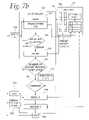
Referring now toFIG. 7 , another example of approaches for fault determination is described. As shown inFIG. 7 , through a coupling network andmodem 761, a packet701 (having pre-set values) is sent fromtransmitters controller 703 of a receiver, and read throughserial communication port 736 of thecontroller 703.
Thepacket 701 includes, for example,preamble byte 732, and atransmitter identification byte 733, and apacket number byte 734, followed byn data bytes 735, D1 through Dn. N may be any integer value. In one example, n=24 and, consequently, 24 bytes of data are used. The rate of the data transmission, or bit rate, can become any speed or any modulation scheme suitable for the modem. In the some examples, a 2400 bps power line modem is used that provides approximately 130 kHz of Frequency Shift Keying (FSK) modulation. However, other numbers of data bytes may be used along with other bit rates and other modulation schemes. In some examples, a longer packet with slower bit rate with a modulation scheme may have better chance of intermittent fault detection than a shorter packet with higher bit rate with another modulation scheme.
Thecontroller 703 of the receiver, after detecting thepreamble byte 732, followed byidentification byte 733, then reads the rest of the bytes (step760) one at a time and store the packet intointernal memory space 741. In another part of thememory 741, thepacket 701 is stored as apacket 742 and is used for a comparison with an expected (and previously stored)packet 743. The expectedpacket 743 includes the expected values of information for thepacket 742. The packet information stored in memory can be compared against each of the transmitters.
Thecontroller 703 atstep 762 reads the storedpackets packets FIG. 3 , a fault detection and location decision is made and displayed753 or uploaded to anupper level computer 755. Then, the next packet sent from a transmitter is read atstep 762.
Atstep 764, the error details (including the identity of the transmitter that sent the packet) may be stored. Atstep 766 it is determined if an adequate number of packets has been received in order to determine whether an alarm should be given a user. If the answer atstep 766 is negative, control returns to step760. If the answer is affirmative, execution continues atstep 768 where a comparison is made with athreshold 770. If the number of erred packets exceeds the threshold, aresult 772 is formed as a fault (e.g., “1”) or no-fault (e.g., “0”) result of a particular transmitter as in the table ofFIG. 3 . The final decision on fault determination using the table (stored in memory) is made and communicated to one or more of a port750 (for display on an enunciator751), a communication port752 (for presentation on a display753) and/or port754 (for display on a personal computer755). Depending upon the type of display, graphical images maybe formed to be displayed on some or all of the mentioned external devices.
As described herein, a pause may be inserted between transmitted packets. In one example, the pause between two consecutive packets, in a system using a microcontroller of 8-bits and 20 MHz speed, is about 100 milliseconds. The pause time is selected so as to be sufficient for processing to occur. For example, the pause duration may be selected to allow for the fault determination process to finish and also for error messages to be sent to external devices (e.g., theenunciator 751, thedisplay 753, and/or the personal computer755). The pause duration can also include time to allow processing to occur for a given number of packets, for example, 1000 packets.
The threshold level of the rate of error that initiates the fault (e.g., “1”) or no-fault (e.g., “0”) can be any predetermined value or, alternatively, be determined after a run of the system under clean electrical wire status. Further, the threshold can be automatically determined using the error rate by comparing the error rates during actual/normal operating status and those of actual intermittent fault status. Before deploying the above-mentioned approaches, a test run may be executed in a staged intermittent fault condition that sets the threshold level for a fault or no-fault boundary, and thus increases the detection probability while at the same time decreasing false alarm and nuisance readings.
Various error rates can be determined. For example, a first error type that can be calculated is a Net Packet Error Rate (NPER), which is the percentage of packets that contained errors out of the total number of received packets. In the NPER case, the lost packets by the error in identification byte(s) are ignored.
Alternatively, a Total Packet Error Rate (TPER), can be calculated. This rate is the percentage of the number of packets received with error out of the total number packets sent.
In another example, a Net Byte Error Rate (NBER) can be calculated. The NBER is the percentage of the number of packets received with just 1 data byte error caused by 1 or 2 bit errors in the byte out of the received packets with no error. The NBER focuses, unlike NPER or TPER, on very short disruptions. Very short disruptions in time rooted from an intermittent fault may cause error in a bit or two in a byte data, not across the data bytes.
Yet another alternative error rate that can be determined is the Total Byte Error Rate (TBER), which is the percentage of the number of packets received with 1 data byte error caused by 1 or 2 bit errors in the byte out of the total number of packets sent. The TBER ignores any disruptions which are long enough to cause errors in multiple data bytes. This rate does not include or consider long disruptions possibly caused by normal switching operations and, as such, could reduce the number of false alarms.
Referring now toFIG. 8 , areceiver 801 receives packets overelectrical wires transmitter 802. If the electrical wire carries DC current, then one of thewires FIG. 8 , both thereceiver 801 and thetransmitter 802 have the same functional structure and includes apower line modem controller receiver 801 includes additional interface outputs orports output 813 is connected to an indicator/enunciator 807 to send an alarm when an intermittent fault is detected. This may be in the form of blinking light (e.g., light emitting diode (LED))and/or audible indication. Theport 813 is used to display the alarm condition on a display806 (e.g., a liquid crystal display (LCD)) with texts and graphics. Theoutput 814 is further used to send the alarm condition to acomputer system 820 viaserial communication port 808 for displaying on a computer screen or for further analysis of the alarm condition data. The errors and error rates discussed herein can be displayed according to any of the display approaches described herein.
Thetransmitter 802 includes thepower line modem 804 and thecontroller 805. Thecontroller 805 is a microcontroller or microprocessor which includes computing code, controls digital logic, and sends bytes of digital data (e.g., packets). The computing code manages the number of packets sent and how often the packets are sent.
Referring now toFIG. 9 , one example of atransmitter 900 is described. Apower line modem 921 in thetransmitter 900 receives the serially transmitted digital data stream from acontroller 903, converts the digital data to analog data, and modulates the analog data in FSK (Frequency Shift Keying) scheme (in whichdigital logic 1 is coded to analog signal of a certain frequency anddigital logic 0 is to another frequency). The modulated signal is amplified by anamplifier 922 and sent through acoupler 923, which sends the modulated signals and blocks all other signals outside the frequency band, to theelectrical wires
The modern921 may be any commercially available modem chip. Themodem 921 may include a filter that band passes only the frequency band used in the particular FSK scheme that is employed. Themodem 921 has four control and data communication lines with thecontroller 903. These include RX control930 for controlling the reception of digital data,TX control 931 for controlling the transmission of digital data, carrier detect (CD) control932 for indicating to thecontroller 903 if and when themodem 922 receives a modulated signal from an electrical wire, and RX/TX control 933 for indicating if a digital signal has been received and is to be transmitted.
A modulated signal automatically is transmitted from themodem 921 and amplified by theamplifier circuit 922. The amplified modulated signal then is presented to the electrical wires via acoupler 923, which passes the signals of the frequency band and blocks all other signals. Thecoupler 923, in one example, is atransformer coil 924 withfiltering capacitors 925 and926. In one approach, the structure of the receiver is identical (or nearly identical with the receiver having ports to communicate with external devices) with the structure of thetransmitter 900.
Various transmission protocols may be used. For example, a byte of any data can be sent from the receiver to indicate to the transmitter to send data.
A packet may be sent to the receiver with various bytes of data. For example, a preamble byte may be included. The next byte is sent to identify the transmitter and the receiver. To take one example, if the identification byte is a preset data value such as a byte data of 10110011, then the receiver checks if the received identification byte is 10110011. If the received identification byte is the same as the preset data, then the receiver is now ready to receive the data stream that follows. One or more bytes can be used for identification purposes.
As mentioned, in one example, the group of data bytes including the preamble, identification, and actual data form a packet. In one approach, one packet is transmitted from a transmitter and reception of the same one packet made by a receiver. In one approach, the transmitter transmits the same one packet repeatedly, with a pause between two packets, until, for example, a set number of packets are sent (e.g., 956 packets). Then, packet transmission resumes. Under an intermittent fault condition, the preamble byte may be noised out, or the identification byte may be contaminated, then the receiver ignores the packet with the contaminated identification byte since the packet is interpreted as not meant to be sent to the receiver. In this case, one packet is lost and a packet error exists.
Thus, approaches are provided to detect the presence and locations of faults within an existing electrical network. The approaches utilize one or more transmitters to send signals (e.g., packets) to one more receivers and based upon the signal received at the receiver, to determine the presence and location of electrical faults. The approaches described herein are easy and cost effective to use, do not rely upon the transmission of high voltage signals, can be implemented at any place within the electrical system, and are not susceptible to false results as have been obtained in previous approaches.
While the invention herein disclosed has been described by means of specific embodiments and applications thereof, numerous modifications and variations could be made thereto by those skilled in the art without departing from the scope of the invention.
Claims (8)
1. A method of determining intermittent electrical faults comprising:
transmitting signals from a plurality of transmitters that are positioned in an electrical network;
receiving the signals transmitted by each of the plurality of transmitters at a single receiver positioned within the electrical network;
at the single receiver, analyzing the received signals and determining from the analyzing of the received signals whether a fault has occurred in the electrical network;
wherein transmitting the signals comprises inserting a random pause duration between successively transmitted signals.
2. The method ofclaim 1 wherein each of the plurality of transmitters has an associated unique combination of bits that uniquely identifies the transmitter and wherein the unique combination bits is included in the signals sent to the receiver.
3. The method ofclaim 2 wherein the receiver analyzes the received combination of bits and compares the combination of bits to an expected combination of bits and when there is not a match, determines that an electrical fault exist.
4. The method ofclaim 3 further comprising determining the location of the electrical fault based upon the analyzing.
5. A fault determination system comprising:
a plurality of transmitters, each of the plurality of transmitters configured to transmit signals across at least a portion of an electrical network;
a single receiver communicatively coupled to the plurality of transmitters, the single receiver configured to receive the signals transmitted by each of the plurality of transmitters and to analyze the received signals and determine from analyzing the received signals when a fault has occurred in the electrical network;
wherein the each of the plurality of transmitters is configured to insert a random pause duration between successively transmitted signals.
6. The system ofclaim 5 wherein each of the plurality of transmitters has a unique combination of bits that identifies each transmitter and the unique combination of bits is included in signals sent to the single receiver.
7. The system ofclaim 6 wherein the single receiver is configured to analyze the received bits and to perform a comparison between the received bits to expected bits and when a match does not exist between the received bits and the expected bits, to determine that a fault exist.
8. The system ofclaim 7 wherein the single receiver is configured to determine the location of the fault based upon the comparison between the received bits and the expected bits.
Priority Applications (10)
| Application Number | Priority Date | Filing Date | Title |
|---|---|---|---|
| US12/262,664US8102779B2 (en) | 2008-10-31 | 2008-10-31 | System and method of detecting and locating intermittent electrical faults in electrical systems |
| US12/464,561US8897635B2 (en) | 2008-10-31 | 2009-05-12 | System and method of detecting and locating intermittent and other faults |
| EP09824037.7AEP2356475A4 (en) | 2008-10-31 | 2009-10-23 | SYSTEM AND METHOD FOR DETECTING AND LOCATING INTERMITTENT ELECTRICAL FAILURES IN ELECTRICAL SYSTEMS |
| PCT/US2009/061770WO2010051221A1 (en) | 2008-10-31 | 2009-10-23 | Housing arrangement for fault determination apparatus and method for installing the same |
| PCT/US2009/061779WO2010051224A1 (en) | 2008-10-31 | 2009-10-23 | System and method of detecting and locating intermittent electrical faults in electrical systems |
| CN2009801435991ACN102246050A (en) | 2008-10-31 | 2009-10-23 | System and method of detecting and locating intermittent electrical faults in electrical systems |
| JP2011534639AJP5840495B2 (en) | 2008-10-31 | 2009-10-23 | System and method for detecting and locating intermittent electrical faults in electrical systems |
| US13/089,906US8711711B2 (en) | 2008-10-31 | 2011-04-19 | System and method of detecting and locating intermittent and other faults |
| US13/355,660US9215045B2 (en) | 2008-10-31 | 2012-01-23 | System and method of detecting and locating intermittent electrical faults in electrical systems |
| US14/261,642US9423443B2 (en) | 2008-10-31 | 2014-04-25 | System and method of detecting and locating intermittent and other faults |
Applications Claiming Priority (1)
| Application Number | Priority Date | Filing Date | Title |
|---|---|---|---|
| US12/262,664US8102779B2 (en) | 2008-10-31 | 2008-10-31 | System and method of detecting and locating intermittent electrical faults in electrical systems |
Related Child Applications (2)
| Application Number | Title | Priority Date | Filing Date |
|---|---|---|---|
| US12/464,561Continuation-In-PartUS8897635B2 (en) | 2008-10-31 | 2009-05-12 | System and method of detecting and locating intermittent and other faults |
| US13/355,660ContinuationUS9215045B2 (en) | 2008-10-31 | 2012-01-23 | System and method of detecting and locating intermittent electrical faults in electrical systems |
Publications (2)
| Publication Number | Publication Date |
|---|---|
| US20100110900A1 US20100110900A1 (en) | 2010-05-06 |
| US8102779B2true US8102779B2 (en) | 2012-01-24 |
Family
ID=42131260
Family Applications (2)
| Application Number | Title | Priority Date | Filing Date |
|---|---|---|---|
| US12/262,664Active2030-06-10US8102779B2 (en) | 2008-10-31 | 2008-10-31 | System and method of detecting and locating intermittent electrical faults in electrical systems |
| US13/355,660Active2030-04-26US9215045B2 (en) | 2008-10-31 | 2012-01-23 | System and method of detecting and locating intermittent electrical faults in electrical systems |
Family Applications After (1)
| Application Number | Title | Priority Date | Filing Date |
|---|---|---|---|
| US13/355,660Active2030-04-26US9215045B2 (en) | 2008-10-31 | 2012-01-23 | System and method of detecting and locating intermittent electrical faults in electrical systems |
Country Status (1)
| Country | Link |
|---|---|
| US (2) | US8102779B2 (en) |
Cited By (164)
| Publication number | Priority date | Publication date | Assignee | Title |
|---|---|---|---|---|
| US20120119753A1 (en)* | 2008-10-31 | 2012-05-17 | Kim Charles J | System and Method of Detecting and Locating Intermittent Electrical Faults In Electrical Systems |
| US20160080839A1 (en)* | 2014-09-17 | 2016-03-17 | At&T Intellectual Property I, Lp | Monitoring and mitigating conditions in a communication network |
| US9423443B2 (en) | 2008-10-31 | 2016-08-23 | Howard University | System and method of detecting and locating intermittent and other faults |
| US9461706B1 (en) | 2015-07-31 | 2016-10-04 | At&T Intellectual Property I, Lp | Method and apparatus for exchanging communication signals |
| US9467870B2 (en) | 2013-11-06 | 2016-10-11 | At&T Intellectual Property I, L.P. | Surface-wave communications and methods thereof |
| US9479266B2 (en) | 2013-12-10 | 2016-10-25 | At&T Intellectual Property I, L.P. | Quasi-optical coupler |
| US9490869B1 (en) | 2015-05-14 | 2016-11-08 | At&T Intellectual Property I, L.P. | Transmission medium having multiple cores and methods for use therewith |
| US9503189B2 (en) | 2014-10-10 | 2016-11-22 | At&T Intellectual Property I, L.P. | Method and apparatus for arranging communication sessions in a communication system |
| US9509415B1 (en) | 2015-06-25 | 2016-11-29 | At&T Intellectual Property I, L.P. | Methods and apparatus for inducing a fundamental wave mode on a transmission medium |
| US9520945B2 (en) | 2014-10-21 | 2016-12-13 | At&T Intellectual Property I, L.P. | Apparatus for providing communication services and methods thereof |
| US9525524B2 (en) | 2013-05-31 | 2016-12-20 | At&T Intellectual Property I, L.P. | Remote distributed antenna system |
| US9525210B2 (en) | 2014-10-21 | 2016-12-20 | At&T Intellectual Property I, L.P. | Guided-wave transmission device with non-fundamental mode propagation and methods for use therewith |
| US9531427B2 (en) | 2014-11-20 | 2016-12-27 | At&T Intellectual Property I, L.P. | Transmission device with mode division multiplexing and methods for use therewith |
| US9564947B2 (en) | 2014-10-21 | 2017-02-07 | At&T Intellectual Property I, L.P. | Guided-wave transmission device with diversity and methods for use therewith |
| US9571209B2 (en) | 2014-10-21 | 2017-02-14 | At&T Intellectual Property I, L.P. | Transmission device with impairment compensation and methods for use therewith |
| US9577307B2 (en) | 2014-10-21 | 2017-02-21 | At&T Intellectual Property I, L.P. | Guided-wave transmission device and methods for use therewith |
| US9608692B2 (en) | 2015-06-11 | 2017-03-28 | At&T Intellectual Property I, L.P. | Repeater and methods for use therewith |
| US9608740B2 (en) | 2015-07-15 | 2017-03-28 | At&T Intellectual Property I, L.P. | Method and apparatus for launching a wave mode that mitigates interference |
| US9615269B2 (en) | 2014-10-02 | 2017-04-04 | At&T Intellectual Property I, L.P. | Method and apparatus that provides fault tolerance in a communication network |
| US9628854B2 (en) | 2014-09-29 | 2017-04-18 | At&T Intellectual Property I, L.P. | Method and apparatus for distributing content in a communication network |
| US9628116B2 (en) | 2015-07-14 | 2017-04-18 | At&T Intellectual Property I, L.P. | Apparatus and methods for transmitting wireless signals |
| US9640850B2 (en) | 2015-06-25 | 2017-05-02 | At&T Intellectual Property I, L.P. | Methods and apparatus for inducing a non-fundamental wave mode on a transmission medium |
| US9653770B2 (en) | 2014-10-21 | 2017-05-16 | At&T Intellectual Property I, L.P. | Guided wave coupler, coupling module and methods for use therewith |
| US9654173B2 (en) | 2014-11-20 | 2017-05-16 | At&T Intellectual Property I, L.P. | Apparatus for powering a communication device and methods thereof |
| US9667317B2 (en) | 2015-06-15 | 2017-05-30 | At&T Intellectual Property I, L.P. | Method and apparatus for providing security using network traffic adjustments |
| US9680670B2 (en) | 2014-11-20 | 2017-06-13 | At&T Intellectual Property I, L.P. | Transmission device with channel equalization and control and methods for use therewith |
| US9685992B2 (en) | 2014-10-03 | 2017-06-20 | At&T Intellectual Property I, L.P. | Circuit panel network and methods thereof |
| US9692101B2 (en) | 2014-08-26 | 2017-06-27 | At&T Intellectual Property I, L.P. | Guided wave couplers for coupling electromagnetic waves between a waveguide surface and a surface of a wire |
| US9699785B2 (en) | 2012-12-05 | 2017-07-04 | At&T Intellectual Property I, L.P. | Backhaul link for distributed antenna system |
| US9705561B2 (en) | 2015-04-24 | 2017-07-11 | At&T Intellectual Property I, L.P. | Directional coupling device and methods for use therewith |
| US9705571B2 (en) | 2015-09-16 | 2017-07-11 | At&T Intellectual Property I, L.P. | Method and apparatus for use with a radio distributed antenna system |
| US9722318B2 (en) | 2015-07-14 | 2017-08-01 | At&T Intellectual Property I, L.P. | Method and apparatus for coupling an antenna to a device |
| US9729197B2 (en) | 2015-10-01 | 2017-08-08 | At&T Intellectual Property I, L.P. | Method and apparatus for communicating network management traffic over a network |
| US9735833B2 (en) | 2015-07-31 | 2017-08-15 | At&T Intellectual Property I, L.P. | Method and apparatus for communications management in a neighborhood network |
| US9742462B2 (en) | 2014-12-04 | 2017-08-22 | At&T Intellectual Property I, L.P. | Transmission medium and communication interfaces and methods for use therewith |
| US9749013B2 (en) | 2015-03-17 | 2017-08-29 | At&T Intellectual Property I, L.P. | Method and apparatus for reducing attenuation of electromagnetic waves guided by a transmission medium |
| US9749053B2 (en) | 2015-07-23 | 2017-08-29 | At&T Intellectual Property I, L.P. | Node device, repeater and methods for use therewith |
| US9748626B2 (en) | 2015-05-14 | 2017-08-29 | At&T Intellectual Property I, L.P. | Plurality of cables having different cross-sectional shapes which are bundled together to form a transmission medium |
| US9755697B2 (en) | 2014-09-15 | 2017-09-05 | At&T Intellectual Property I, L.P. | Method and apparatus for sensing a condition in a transmission medium of electromagnetic waves |
| US9762289B2 (en) | 2014-10-14 | 2017-09-12 | At&T Intellectual Property I, L.P. | Method and apparatus for transmitting or receiving signals in a transportation system |
| US9769128B2 (en) | 2015-09-28 | 2017-09-19 | At&T Intellectual Property I, L.P. | Method and apparatus for encryption of communications over a network |
| US9769020B2 (en) | 2014-10-21 | 2017-09-19 | At&T Intellectual Property I, L.P. | Method and apparatus for responding to events affecting communications in a communication network |
| US9780834B2 (en) | 2014-10-21 | 2017-10-03 | At&T Intellectual Property I, L.P. | Method and apparatus for transmitting electromagnetic waves |
| US9793955B2 (en) | 2015-04-24 | 2017-10-17 | At&T Intellectual Property I, Lp | Passive electrical coupling device and methods for use therewith |
| US9793951B2 (en) | 2015-07-15 | 2017-10-17 | At&T Intellectual Property I, L.P. | Method and apparatus for launching a wave mode that mitigates interference |
| US9793954B2 (en) | 2015-04-28 | 2017-10-17 | At&T Intellectual Property I, L.P. | Magnetic coupling device and methods for use therewith |
| US9800327B2 (en) | 2014-11-20 | 2017-10-24 | At&T Intellectual Property I, L.P. | Apparatus for controlling operations of a communication device and methods thereof |
| US9820146B2 (en) | 2015-06-12 | 2017-11-14 | At&T Intellectual Property I, L.P. | Method and apparatus for authentication and identity management of communicating devices |
| US9838896B1 (en) | 2016-12-09 | 2017-12-05 | At&T Intellectual Property I, L.P. | Method and apparatus for assessing network coverage |
| US9836957B2 (en) | 2015-07-14 | 2017-12-05 | At&T Intellectual Property I, L.P. | Method and apparatus for communicating with premises equipment |
| US9847850B2 (en) | 2014-10-14 | 2017-12-19 | At&T Intellectual Property I, L.P. | Method and apparatus for adjusting a mode of communication in a communication network |
| US9847566B2 (en) | 2015-07-14 | 2017-12-19 | At&T Intellectual Property I, L.P. | Method and apparatus for adjusting a field of a signal to mitigate interference |
| US9853342B2 (en) | 2015-07-14 | 2017-12-26 | At&T Intellectual Property I, L.P. | Dielectric transmission medium connector and methods for use therewith |
| US9860075B1 (en) | 2016-08-26 | 2018-01-02 | At&T Intellectual Property I, L.P. | Method and communication node for broadband distribution |
| US9865911B2 (en) | 2015-06-25 | 2018-01-09 | At&T Intellectual Property I, L.P. | Waveguide system for slot radiating first electromagnetic waves that are combined into a non-fundamental wave mode second electromagnetic wave on a transmission medium |
| US9866309B2 (en) | 2015-06-03 | 2018-01-09 | At&T Intellectual Property I, Lp | Host node device and methods for use therewith |
| US9871282B2 (en) | 2015-05-14 | 2018-01-16 | At&T Intellectual Property I, L.P. | At least one transmission medium having a dielectric surface that is covered at least in part by a second dielectric |
| US9871283B2 (en) | 2015-07-23 | 2018-01-16 | At&T Intellectual Property I, Lp | Transmission medium having a dielectric core comprised of plural members connected by a ball and socket configuration |
| US9876605B1 (en) | 2016-10-21 | 2018-01-23 | At&T Intellectual Property I, L.P. | Launcher and coupling system to support desired guided wave mode |
| US9876570B2 (en) | 2015-02-20 | 2018-01-23 | At&T Intellectual Property I, Lp | Guided-wave transmission device with non-fundamental mode propagation and methods for use therewith |
| US9876264B2 (en) | 2015-10-02 | 2018-01-23 | At&T Intellectual Property I, Lp | Communication system, guided wave switch and methods for use therewith |
| US9882277B2 (en) | 2015-10-02 | 2018-01-30 | At&T Intellectual Property I, Lp | Communication device and antenna assembly with actuated gimbal mount |
| US9882257B2 (en) | 2015-07-14 | 2018-01-30 | At&T Intellectual Property I, L.P. | Method and apparatus for launching a wave mode that mitigates interference |
| US9893795B1 (en) | 2016-12-07 | 2018-02-13 | At&T Intellectual Property I, Lp | Method and repeater for broadband distribution |
| US9904535B2 (en) | 2015-09-14 | 2018-02-27 | At&T Intellectual Property I, L.P. | Method and apparatus for distributing software |
| US9913139B2 (en) | 2015-06-09 | 2018-03-06 | At&T Intellectual Property I, L.P. | Signal fingerprinting for authentication of communicating devices |
| US9912382B2 (en) | 2015-06-03 | 2018-03-06 | At&T Intellectual Property I, Lp | Network termination and methods for use therewith |
| US9912027B2 (en) | 2015-07-23 | 2018-03-06 | At&T Intellectual Property I, L.P. | Method and apparatus for exchanging communication signals |
| US9912419B1 (en) | 2016-08-24 | 2018-03-06 | At&T Intellectual Property I, L.P. | Method and apparatus for managing a fault in a distributed antenna system |
| US9911020B1 (en) | 2016-12-08 | 2018-03-06 | At&T Intellectual Property I, L.P. | Method and apparatus for tracking via a radio frequency identification device |
| US9917341B2 (en) | 2015-05-27 | 2018-03-13 | At&T Intellectual Property I, L.P. | Apparatus and method for launching electromagnetic waves and for modifying radial dimensions of the propagating electromagnetic waves |
| US9927517B1 (en) | 2016-12-06 | 2018-03-27 | At&T Intellectual Property I, L.P. | Apparatus and methods for sensing rainfall |
| US9948354B2 (en) | 2015-04-28 | 2018-04-17 | At&T Intellectual Property I, L.P. | Magnetic coupling device with reflective plate and methods for use therewith |
| US9948333B2 (en) | 2015-07-23 | 2018-04-17 | At&T Intellectual Property I, L.P. | Method and apparatus for wireless communications to mitigate interference |
| US9954287B2 (en) | 2014-11-20 | 2018-04-24 | At&T Intellectual Property I, L.P. | Apparatus for converting wireless signals and electromagnetic waves and methods thereof |
| US9967173B2 (en) | 2015-07-31 | 2018-05-08 | At&T Intellectual Property I, L.P. | Method and apparatus for authentication and identity management of communicating devices |
| US9973940B1 (en) | 2017-02-27 | 2018-05-15 | At&T Intellectual Property I, L.P. | Apparatus and methods for dynamic impedance matching of a guided wave launcher |
| US9991580B2 (en) | 2016-10-21 | 2018-06-05 | At&T Intellectual Property I, L.P. | Launcher and coupling system for guided wave mode cancellation |
| US9998870B1 (en) | 2016-12-08 | 2018-06-12 | At&T Intellectual Property I, L.P. | Method and apparatus for proximity sensing |
| US9999038B2 (en) | 2013-05-31 | 2018-06-12 | At&T Intellectual Property I, L.P. | Remote distributed antenna system |
| US9997819B2 (en) | 2015-06-09 | 2018-06-12 | At&T Intellectual Property I, L.P. | Transmission medium and method for facilitating propagation of electromagnetic waves via a core |
| US10009067B2 (en) | 2014-12-04 | 2018-06-26 | At&T Intellectual Property I, L.P. | Method and apparatus for configuring a communication interface |
| US10009063B2 (en) | 2015-09-16 | 2018-06-26 | At&T Intellectual Property I, L.P. | Method and apparatus for use with a radio distributed antenna system having an out-of-band reference signal |
| US10009901B2 (en) | 2015-09-16 | 2018-06-26 | At&T Intellectual Property I, L.P. | Method, apparatus, and computer-readable storage medium for managing utilization of wireless resources between base stations |
| US10009065B2 (en) | 2012-12-05 | 2018-06-26 | At&T Intellectual Property I, L.P. | Backhaul link for distributed antenna system |
| US10020844B2 (en) | 2016-12-06 | 2018-07-10 | T&T Intellectual Property I, L.P. | Method and apparatus for broadcast communication via guided waves |
| US10020587B2 (en) | 2015-07-31 | 2018-07-10 | At&T Intellectual Property I, L.P. | Radial antenna and methods for use therewith |
| US10027397B2 (en) | 2016-12-07 | 2018-07-17 | At&T Intellectual Property I, L.P. | Distributed antenna system and methods for use therewith |
| US10033107B2 (en) | 2015-07-14 | 2018-07-24 | At&T Intellectual Property I, L.P. | Method and apparatus for coupling an antenna to a device |
| US10033108B2 (en) | 2015-07-14 | 2018-07-24 | At&T Intellectual Property I, L.P. | Apparatus and methods for generating an electromagnetic wave having a wave mode that mitigates interference |
| US10044409B2 (en) | 2015-07-14 | 2018-08-07 | At&T Intellectual Property I, L.P. | Transmission medium and methods for use therewith |
| US10051629B2 (en) | 2015-09-16 | 2018-08-14 | At&T Intellectual Property I, L.P. | Method and apparatus for use with a radio distributed antenna system having an in-band reference signal |
| US10051483B2 (en) | 2015-10-16 | 2018-08-14 | At&T Intellectual Property I, L.P. | Method and apparatus for directing wireless signals |
| US10069535B2 (en) | 2016-12-08 | 2018-09-04 | At&T Intellectual Property I, L.P. | Apparatus and methods for launching electromagnetic waves having a certain electric field structure |
| US10074890B2 (en) | 2015-10-02 | 2018-09-11 | At&T Intellectual Property I, L.P. | Communication device and antenna with integrated light assembly |
| US10079661B2 (en) | 2015-09-16 | 2018-09-18 | At&T Intellectual Property I, L.P. | Method and apparatus for use with a radio distributed antenna system having a clock reference |
| US10090594B2 (en) | 2016-11-23 | 2018-10-02 | At&T Intellectual Property I, L.P. | Antenna system having structural configurations for assembly |
| US10090606B2 (en) | 2015-07-15 | 2018-10-02 | At&T Intellectual Property I, L.P. | Antenna system with dielectric array and methods for use therewith |
| US10103801B2 (en) | 2015-06-03 | 2018-10-16 | At&T Intellectual Property I, L.P. | Host node device and methods for use therewith |
| US10103422B2 (en) | 2016-12-08 | 2018-10-16 | At&T Intellectual Property I, L.P. | Method and apparatus for mounting network devices |
| US10135145B2 (en) | 2016-12-06 | 2018-11-20 | At&T Intellectual Property I, L.P. | Apparatus and methods for generating an electromagnetic wave along a transmission medium |
| US10136434B2 (en) | 2015-09-16 | 2018-11-20 | At&T Intellectual Property I, L.P. | Method and apparatus for use with a radio distributed antenna system having an ultra-wideband control channel |
| US10135146B2 (en) | 2016-10-18 | 2018-11-20 | At&T Intellectual Property I, L.P. | Apparatus and methods for launching guided waves via circuits |
| US10135147B2 (en) | 2016-10-18 | 2018-11-20 | At&T Intellectual Property I, L.P. | Apparatus and methods for launching guided waves via an antenna |
| US10142086B2 (en) | 2015-06-11 | 2018-11-27 | At&T Intellectual Property I, L.P. | Repeater and methods for use therewith |
| US10139820B2 (en) | 2016-12-07 | 2018-11-27 | At&T Intellectual Property I, L.P. | Method and apparatus for deploying equipment of a communication system |
| US10148016B2 (en) | 2015-07-14 | 2018-12-04 | At&T Intellectual Property I, L.P. | Apparatus and methods for communicating utilizing an antenna array |
| US10144036B2 (en) | 2015-01-30 | 2018-12-04 | At&T Intellectual Property I, L.P. | Method and apparatus for mitigating interference affecting a propagation of electromagnetic waves guided by a transmission medium |
| US10154493B2 (en) | 2015-06-03 | 2018-12-11 | At&T Intellectual Property I, L.P. | Network termination and methods for use therewith |
| US10168695B2 (en) | 2016-12-07 | 2019-01-01 | At&T Intellectual Property I, L.P. | Method and apparatus for controlling an unmanned aircraft |
| US10170840B2 (en) | 2015-07-14 | 2019-01-01 | At&T Intellectual Property I, L.P. | Apparatus and methods for sending or receiving electromagnetic signals |
| US10178445B2 (en) | 2016-11-23 | 2019-01-08 | At&T Intellectual Property I, L.P. | Methods, devices, and systems for load balancing between a plurality of waveguides |
| US10205655B2 (en) | 2015-07-14 | 2019-02-12 | At&T Intellectual Property I, L.P. | Apparatus and methods for communicating utilizing an antenna array and multiple communication paths |
| US10225025B2 (en) | 2016-11-03 | 2019-03-05 | At&T Intellectual Property I, L.P. | Method and apparatus for detecting a fault in a communication system |
| US10224634B2 (en) | 2016-11-03 | 2019-03-05 | At&T Intellectual Property I, L.P. | Methods and apparatus for adjusting an operational characteristic of an antenna |
| US10243784B2 (en) | 2014-11-20 | 2019-03-26 | At&T Intellectual Property I, L.P. | System for generating topology information and methods thereof |
| US10243270B2 (en) | 2016-12-07 | 2019-03-26 | At&T Intellectual Property I, L.P. | Beam adaptive multi-feed dielectric antenna system and methods for use therewith |
| US10264586B2 (en) | 2016-12-09 | 2019-04-16 | At&T Mobility Ii Llc | Cloud-based packet controller and methods for use therewith |
| US10291311B2 (en) | 2016-09-09 | 2019-05-14 | At&T Intellectual Property I, L.P. | Method and apparatus for mitigating a fault in a distributed antenna system |
| US10291334B2 (en) | 2016-11-03 | 2019-05-14 | At&T Intellectual Property I, L.P. | System for detecting a fault in a communication system |
| US10298293B2 (en) | 2017-03-13 | 2019-05-21 | At&T Intellectual Property I, L.P. | Apparatus of communication utilizing wireless network devices |
| US10305190B2 (en) | 2016-12-01 | 2019-05-28 | At&T Intellectual Property I, L.P. | Reflecting dielectric antenna system and methods for use therewith |
| US10312567B2 (en) | 2016-10-26 | 2019-06-04 | At&T Intellectual Property I, L.P. | Launcher with planar strip antenna and methods for use therewith |
| US10320586B2 (en) | 2015-07-14 | 2019-06-11 | At&T Intellectual Property I, L.P. | Apparatus and methods for generating non-interfering electromagnetic waves on an insulated transmission medium |
| US10326689B2 (en) | 2016-12-08 | 2019-06-18 | At&T Intellectual Property I, L.P. | Method and system for providing alternative communication paths |
| US10326494B2 (en) | 2016-12-06 | 2019-06-18 | At&T Intellectual Property I, L.P. | Apparatus for measurement de-embedding and methods for use therewith |
| US10340603B2 (en) | 2016-11-23 | 2019-07-02 | At&T Intellectual Property I, L.P. | Antenna system having shielded structural configurations for assembly |
| US10340601B2 (en) | 2016-11-23 | 2019-07-02 | At&T Intellectual Property I, L.P. | Multi-antenna system and methods for use therewith |
| US10340600B2 (en) | 2016-10-18 | 2019-07-02 | At&T Intellectual Property I, L.P. | Apparatus and methods for launching guided waves via plural waveguide systems |
| US10340983B2 (en) | 2016-12-09 | 2019-07-02 | At&T Intellectual Property I, L.P. | Method and apparatus for surveying remote sites via guided wave communications |
| US10340573B2 (en) | 2016-10-26 | 2019-07-02 | At&T Intellectual Property I, L.P. | Launcher with cylindrical coupling device and methods for use therewith |
| US10341142B2 (en) | 2015-07-14 | 2019-07-02 | At&T Intellectual Property I, L.P. | Apparatus and methods for generating non-interfering electromagnetic waves on an uninsulated conductor |
| US10348391B2 (en) | 2015-06-03 | 2019-07-09 | At&T Intellectual Property I, L.P. | Client node device with frequency conversion and methods for use therewith |
| US10355367B2 (en) | 2015-10-16 | 2019-07-16 | At&T Intellectual Property I, L.P. | Antenna structure for exchanging wireless signals |
| US10361489B2 (en) | 2016-12-01 | 2019-07-23 | At&T Intellectual Property I, L.P. | Dielectric dish antenna system and methods for use therewith |
| US10359749B2 (en) | 2016-12-07 | 2019-07-23 | At&T Intellectual Property I, L.P. | Method and apparatus for utilities management via guided wave communication |
| US10374316B2 (en) | 2016-10-21 | 2019-08-06 | At&T Intellectual Property I, L.P. | System and dielectric antenna with non-uniform dielectric |
| US10382976B2 (en) | 2016-12-06 | 2019-08-13 | At&T Intellectual Property I, L.P. | Method and apparatus for managing wireless communications based on communication paths and network device positions |
| US10389037B2 (en) | 2016-12-08 | 2019-08-20 | At&T Intellectual Property I, L.P. | Apparatus and methods for selecting sections of an antenna array and use therewith |
| US10389029B2 (en) | 2016-12-07 | 2019-08-20 | At&T Intellectual Property I, L.P. | Multi-feed dielectric antenna system with core selection and methods for use therewith |
| US10396887B2 (en) | 2015-06-03 | 2019-08-27 | At&T Intellectual Property I, L.P. | Client node device and methods for use therewith |
| US10411356B2 (en) | 2016-12-08 | 2019-09-10 | At&T Intellectual Property I, L.P. | Apparatus and methods for selectively targeting communication devices with an antenna array |
| US10439675B2 (en) | 2016-12-06 | 2019-10-08 | At&T Intellectual Property I, L.P. | Method and apparatus for repeating guided wave communication signals |
| US10446936B2 (en) | 2016-12-07 | 2019-10-15 | At&T Intellectual Property I, L.P. | Multi-feed dielectric antenna system and methods for use therewith |
| US10498044B2 (en) | 2016-11-03 | 2019-12-03 | At&T Intellectual Property I, L.P. | Apparatus for configuring a surface of an antenna |
| US10530505B2 (en) | 2016-12-08 | 2020-01-07 | At&T Intellectual Property I, L.P. | Apparatus and methods for launching electromagnetic waves along a transmission medium |
| US10535928B2 (en) | 2016-11-23 | 2020-01-14 | At&T Intellectual Property I, L.P. | Antenna system and methods for use therewith |
| US10547348B2 (en) | 2016-12-07 | 2020-01-28 | At&T Intellectual Property I, L.P. | Method and apparatus for switching transmission mediums in a communication system |
| US10601494B2 (en) | 2016-12-08 | 2020-03-24 | At&T Intellectual Property I, L.P. | Dual-band communication device and method for use therewith |
| US10637149B2 (en) | 2016-12-06 | 2020-04-28 | At&T Intellectual Property I, L.P. | Injection molded dielectric antenna and methods for use therewith |
| US10650940B2 (en) | 2015-05-15 | 2020-05-12 | At&T Intellectual Property I, L.P. | Transmission medium having a conductive material and methods for use therewith |
| US10665942B2 (en) | 2015-10-16 | 2020-05-26 | At&T Intellectual Property I, L.P. | Method and apparatus for adjusting wireless communications |
| US10679767B2 (en) | 2015-05-15 | 2020-06-09 | At&T Intellectual Property I, L.P. | Transmission medium having a conductive material and methods for use therewith |
| US10694379B2 (en) | 2016-12-06 | 2020-06-23 | At&T Intellectual Property I, L.P. | Waveguide system with device-based authentication and methods for use therewith |
| US10727599B2 (en) | 2016-12-06 | 2020-07-28 | At&T Intellectual Property I, L.P. | Launcher with slot antenna and methods for use therewith |
| US10755542B2 (en) | 2016-12-06 | 2020-08-25 | At&T Intellectual Property I, L.P. | Method and apparatus for surveillance via guided wave communication |
| US10777873B2 (en) | 2016-12-08 | 2020-09-15 | At&T Intellectual Property I, L.P. | Method and apparatus for mounting network devices |
| US10784670B2 (en) | 2015-07-23 | 2020-09-22 | At&T Intellectual Property I, L.P. | Antenna support for aligning an antenna |
| US10811767B2 (en) | 2016-10-21 | 2020-10-20 | At&T Intellectual Property I, L.P. | System and dielectric antenna with convex dielectric radome |
| US10819035B2 (en) | 2016-12-06 | 2020-10-27 | At&T Intellectual Property I, L.P. | Launcher with helical antenna and methods for use therewith |
| US10916969B2 (en) | 2016-12-08 | 2021-02-09 | At&T Intellectual Property I, L.P. | Method and apparatus for providing power using an inductive coupling |
| US10938108B2 (en) | 2016-12-08 | 2021-03-02 | At&T Intellectual Property I, L.P. | Frequency selective multi-feed dielectric antenna system and methods for use therewith |
| US11032819B2 (en) | 2016-09-15 | 2021-06-08 | At&T Intellectual Property I, L.P. | Method and apparatus for use with a radio distributed antenna system having a control channel reference signal |
| US11368384B2 (en) | 2016-03-02 | 2022-06-21 | Fisher-Rosemount Systems, Inc. | Detecting and locating process control communication line faults from a handheld maintenance tool |
Families Citing this family (14)
| Publication number | Priority date | Publication date | Assignee | Title |
|---|---|---|---|---|
| US8897635B2 (en)* | 2008-10-31 | 2014-11-25 | Howard University | System and method of detecting and locating intermittent and other faults |
| US9680722B2 (en)* | 2010-09-30 | 2017-06-13 | Telefonaktiebolaget Lm Ericsson (Publ) | Method for determining a severity of a network incident |
| US9727431B2 (en)* | 2013-12-30 | 2017-08-08 | Sital Ltd. | Communication monitoring system |
| CN105281806A (en)* | 2015-11-10 | 2016-01-27 | Comlab(北京)通信系统设备有限公司 | FPGA-based direct sequence spread spectrum system range finding positioning method |
| US10784986B2 (en) | 2017-02-28 | 2020-09-22 | Intel Corporation | Forward error correction mechanism for peripheral component interconnect-express (PCI-e) |
| US10250436B2 (en) | 2017-03-01 | 2019-04-02 | Intel Corporation | Applying framing rules for a high speed data link |
| US10771189B2 (en) | 2018-12-18 | 2020-09-08 | Intel Corporation | Forward error correction mechanism for data transmission across multi-lane links |
| US11637657B2 (en) | 2019-02-15 | 2023-04-25 | Intel Corporation | Low-latency forward error correction for high-speed serial links |
| US11249837B2 (en) | 2019-03-01 | 2022-02-15 | Intel Corporation | Flit-based parallel-forward error correction and parity |
| US11296994B2 (en) | 2019-05-13 | 2022-04-05 | Intel Corporation | Ordered sets for high-speed interconnects |
| EP3799320A1 (en)* | 2019-09-27 | 2021-03-31 | Gulfstream Aerospace Corporation | System and methods of employing data over power in aircraft |
| US11740958B2 (en) | 2019-11-27 | 2023-08-29 | Intel Corporation | Multi-protocol support on common physical layer |
| US12189470B2 (en) | 2020-09-18 | 2025-01-07 | Intel Corporation | Forward error correction and cyclic redundancy check mechanisms for latency-critical coherency and memory interconnects |
| CN113408145B (en)* | 2021-07-14 | 2023-05-23 | 西安邮电大学 | Workshop key manufacturing resource SIS identification method for reversible recovery fault |
Citations (35)
| Publication number | Priority date | Publication date | Assignee | Title |
|---|---|---|---|---|
| US4868826A (en)* | 1987-08-31 | 1989-09-19 | Triplex | Fault-tolerant output circuits |
| US4887041A (en) | 1988-02-17 | 1989-12-12 | University Of Connecticut | Method and instrumentation for the detection, location and characterization of partial discharges and faults in electric power cables |
| US4929887A (en) | 1989-01-19 | 1990-05-29 | Minnesota Mining And Manufacturing Company | Electrical outlet monitor |
| US5029274A (en) | 1988-07-14 | 1991-07-02 | Cline Professional Corp. | Apparatus and method for testing the integrity of wiring ensembles |
| US5237511A (en)* | 1990-10-29 | 1993-08-17 | Westronic, Inc. | Distribution automation smart remote terminal unit |
| US5448176A (en) | 1993-12-30 | 1995-09-05 | The University Of Connecticut | Cable fault detection using a high voltage alternating polarity DC signal superposed with a system frequency AC signal |
| US5600248A (en) | 1995-06-21 | 1997-02-04 | Dipl.-Ing H. Horstmann Gmbh | Fault distance locator for underground cable circuits |
| US5729144A (en) | 1996-12-02 | 1998-03-17 | Cummins; Kenneth L. | Systems and methods for determining location of a fault on an electric utility power distribution system |
| US5784393A (en) | 1995-03-01 | 1998-07-21 | Unisys Corporation | Method and apparatus for providing fault detection to a bus within a computer system |
| US5790537A (en) | 1996-05-15 | 1998-08-04 | Mcgill University | Interference suppression in DS-CDMA systems |
| US6181140B1 (en) | 1998-06-08 | 2001-01-30 | Norscan Inc. | Method of estimating the location of a cable break including a means to measure resistive fault levels for cable sections |
| US6198401B1 (en) | 1999-02-12 | 2001-03-06 | Mcgraw Edison Company | Detection of sub-cycle, self-clearing faults |
| US6313642B1 (en) | 1995-03-13 | 2001-11-06 | Square D Company | Apparatus and method for testing an arcing fault detection system |
| US6385561B1 (en) | 1996-09-28 | 2002-05-07 | University Of Strathclyde | Automatic fault location in cabling systems |
| US6477475B1 (en)* | 1998-11-12 | 2002-11-05 | Nippon Kouatsu Electric Co., Ltd. | Fault point location system |
| US20030085715A1 (en) | 2001-08-15 | 2003-05-08 | David Lubkeman | System and method for locating a fault on ungrounded and high-impedance grounded power systems |
| US20030125893A1 (en) | 2001-07-07 | 2003-07-03 | Furse Cynthia M. | Frequency domain reflectometry system for testing wires and cables utilizing in-situ connectors, passive connectivity, cable fray detection, and live wire testing |
| US6646447B2 (en) | 1999-12-30 | 2003-11-11 | Ambient Corporation | Identifying one of a plurality of wires of a power transmission cable |
| US20040017203A1 (en) | 2001-09-20 | 2004-01-29 | Becker Thomas P. | Fuse saving tester for fused circuit |
| US6725176B1 (en) | 2001-08-03 | 2004-04-20 | Centilliune Communications, Inc. | Loop diagnostics for ADSL systems |
| US6759851B2 (en) | 2002-07-02 | 2004-07-06 | Delphi Technologies, Inc. | Method and apparatus for control and fault detection of an electric load circuit |
| US6842011B1 (en) | 2002-06-27 | 2005-01-11 | Nortel Networks Limited | Method and apparatus for locating impedance mismatches in a radio frequency communication system |
| US6856936B1 (en) | 2001-08-02 | 2005-02-15 | Turnstone Systems, Inc. | Method and system to provide an improved time domain reflectrometry technique |
| US6927579B2 (en) | 2001-01-24 | 2005-08-09 | Astronics Advanced Electronic Systems, Corp. | Parallel arc fault diagnostic for aircraft wiring |
| US6934655B2 (en) | 2001-03-16 | 2005-08-23 | Mindspeed Technologies, Inc. | Method and apparatus for transmission line analysis |
| US20050231326A1 (en) | 1999-01-22 | 2005-10-20 | Marc Enrico | Maintenance of an anticollision channel in an electronic identification system |
| US6965303B2 (en) | 2002-12-10 | 2005-11-15 | Current Technologies, Llc | Power line communication system and method |
| US6972574B2 (en) | 2001-01-31 | 2005-12-06 | Cm Technologies Corporation | Method and apparatus for monitoring integrity of wires or electrical cables |
| US20060061368A1 (en) | 2002-11-19 | 2006-03-23 | University Of Utah Research Foundation. | Device and method for detecting anomolies in a wire and related sensing methods |
| US7319574B2 (en) | 2005-05-23 | 2008-01-15 | Eaton Corporation | Arc fault detection apparatus, method and system for an underground electrical conductor |
| US7368919B2 (en) | 2004-09-02 | 2008-05-06 | Ziota Technology Inc. | Wireless portable automated harness scanner system and method therefor |
| US7432720B1 (en) | 2006-08-04 | 2008-10-07 | Cisco Technology, Inc. | Method and system for isolated current and voltage monitoring |
| US20080273527A1 (en)* | 2007-05-03 | 2008-11-06 | The University Of Leicester | Distributed system |
| US20090228223A1 (en) | 2008-03-04 | 2009-09-10 | Zhenning Liu | Power line communication based aircraft power distribution system with real time wiring integrity monitoring capability |
| US20100171630A1 (en) | 2009-01-07 | 2010-07-08 | Michael Alexander Carralero | Vehicle health management system |
Family Cites Families (40)
| Publication number | Priority date | Publication date | Assignee | Title |
|---|---|---|---|---|
| US4022988A (en) | 1976-06-14 | 1977-05-10 | Bell Telephone Laboratories, Incorporated | Fault locating apparatus for digital transmission system |
| US4414539A (en) | 1978-12-22 | 1983-11-08 | The Boeing Company | Built-in passive fault detection circuitry for an aircraft's electrical/electronic systems |
| US5715407A (en) | 1992-03-06 | 1998-02-03 | Rambus, Inc. | Process and apparatus for collision detection on a parallel bus by monitoring a first line of the bus during even bus cycles for indications of overlapping packets |
| DE4427253C2 (en) | 1994-07-30 | 1996-05-23 | Kiekert Ag | Locking system for a motor vehicle |
| US5682100A (en) | 1995-09-06 | 1997-10-28 | Electric Power Research Institute Inc. | System and method for locating faults in electric power cables |
| JPH11239160A (en) | 1998-02-24 | 1999-08-31 | Toshiba Corp | Data transmission equipment |
| JP2002158668A (en) | 2000-11-17 | 2002-05-31 | Denso Corp | Abnormality detector of network system for vehicle |
| EP1345354A1 (en)* | 2002-03-13 | 2003-09-17 | Alcatel | Electrical network for data transmission |
| US20030194588A1 (en) | 2002-04-10 | 2003-10-16 | Laukhuf Gregg E. | Worksurface power modules powered by fuel cells |
| AU2003234448A1 (en)* | 2002-05-06 | 2003-11-11 | Enikia Llc | Method and system for power line network fault detection and quality monitoring |
| US6756776B2 (en) | 2002-05-28 | 2004-06-29 | Amperion, Inc. | Method and device for installing and removing a current transformer on and from a current-carrying power line |
| US7319411B2 (en) | 2002-07-18 | 2008-01-15 | Kmg2 Sensors Corporation | Network of sensor nodes assemblies and method of remote sensing within liquid environments |
| US7250772B2 (en) | 2002-11-19 | 2007-07-31 | University Of Utah Research Foundation | Method and apparatus for characterizing a signal path carrying an operational signal |
| US20050049754A1 (en) | 2003-08-29 | 2005-03-03 | Craig Ogawa | Power and data configurations for building automation systems |
| US7165200B2 (en) | 2004-02-04 | 2007-01-16 | University Of Utah Research Foundation | System and method for characterizing a signal path using a sub-chip sampler |
| US7414380B2 (en) | 2004-09-21 | 2008-08-19 | Lear Corporation | Apparatus for inductively recharging batteries of a portable convenience device |
| US7724650B2 (en) | 2004-11-30 | 2010-05-25 | Cisco Technology, Inc. | Multi-station physical layer communication over TP cable |
| EP1688811A2 (en) | 2005-02-08 | 2006-08-09 | Relcom, Inc. | Networks for process control |
| JPWO2006120757A1 (en) | 2005-05-11 | 2008-12-18 | 株式会社日立製作所 | Vehicles and communication and control devices in vehicles |
| US7315768B2 (en) | 2006-02-15 | 2008-01-01 | International Business Machines Corporation | Remote monitoring and servicing of computer data centers |
| US8232667B2 (en) | 2006-02-24 | 2012-07-31 | Bendix Commercial Vehicle Systems Llc | System and method for data transmission over a power line of a switch mode power supply by frequency modulating the switch frequency thereof |
| US20070217414A1 (en) | 2006-03-14 | 2007-09-20 | Berkman William H | System and method for multicasting over power lines |
| US20070223165A1 (en) | 2006-03-22 | 2007-09-27 | Itri Benedict A | Line powering in a multi-line environment |
| US7812617B2 (en) | 2006-07-07 | 2010-10-12 | Sital Technology & Hw Design 1997 Ltd. | System and method for detecting and locating faults in electronic communication bus systems |
| EP1895180A2 (en) | 2006-08-30 | 2008-03-05 | Ebara Corporation | Magnetic bearing device, rotating system therewith and method of identification of the model of the main unit in a rotating system |
| TWI350071B (en)* | 2006-09-11 | 2011-10-01 | Univ Nat Taiwan Science Tech | Detection system for identifying faults in a passive optical network |
| GB2443002A (en)* | 2006-10-16 | 2008-04-23 | Converteam Ltd | dc power distribution system |
| FR2907910B1 (en) | 2006-10-25 | 2009-01-16 | Commissariat Energie Atomique | METHOD AND DEVICE FOR ANALYZING ELECTRICAL CABLES NETWORKS BY PSEUDO-RANDOM SEQUENCES |
| US7496472B2 (en) | 2007-01-25 | 2009-02-24 | Johnson Controls Technology Company | Method and system for assessing performance of control systems |
| GB2463827B (en) | 2007-07-17 | 2012-09-05 | Johnson Controls Tech Co | Extremum seeking control with actuator saturation control |
| US20090045925A1 (en) | 2007-08-17 | 2009-02-19 | Franklin Fueling Systems, Inc. | System, Apparatus, and Method for Communicating Sensor Information of a System Component that is Disposed in a Hazardous Location |
| US8442702B2 (en) | 2008-10-22 | 2013-05-14 | Airbus Operations Gmbh | Fault diagnosis device and method for optimizing maintenance measures in technical systems |
| US7986585B2 (en) | 2008-10-30 | 2011-07-26 | The United States Of America As Represented By The Secretary Of The Navy | Reception of uplink data from sonobuoys |
| US8711711B2 (en) | 2008-10-31 | 2014-04-29 | Howard University | System and method of detecting and locating intermittent and other faults |
| US8102779B2 (en) | 2008-10-31 | 2012-01-24 | Howard University | System and method of detecting and locating intermittent electrical faults in electrical systems |
| US8897635B2 (en) | 2008-10-31 | 2014-11-25 | Howard University | System and method of detecting and locating intermittent and other faults |
| TWI400900B (en)* | 2009-01-20 | 2013-07-01 | Univ Nat Chiao Tung | Optical sensing system with self - sensing mechanism |
| US9753455B2 (en) | 2009-06-22 | 2017-09-05 | Johnson Controls Technology Company | Building management system with fault analysis |
| US8532839B2 (en) | 2009-06-22 | 2013-09-10 | Johnson Controls Technology Company | Systems and methods for statistical control and fault detection in a building management system |
| US9606520B2 (en) | 2009-06-22 | 2017-03-28 | Johnson Controls Technology Company | Automated fault detection and diagnostics in a building management system |
- 2008
- 2008-10-31USUS12/262,664patent/US8102779B2/enactiveActive
- 2012
- 2012-01-23USUS13/355,660patent/US9215045B2/enactiveActive
Patent Citations (36)
| Publication number | Priority date | Publication date | Assignee | Title |
|---|---|---|---|---|
| US4868826A (en)* | 1987-08-31 | 1989-09-19 | Triplex | Fault-tolerant output circuits |
| US4887041A (en) | 1988-02-17 | 1989-12-12 | University Of Connecticut | Method and instrumentation for the detection, location and characterization of partial discharges and faults in electric power cables |
| US5029274A (en) | 1988-07-14 | 1991-07-02 | Cline Professional Corp. | Apparatus and method for testing the integrity of wiring ensembles |
| US4929887A (en) | 1989-01-19 | 1990-05-29 | Minnesota Mining And Manufacturing Company | Electrical outlet monitor |
| US5237511A (en)* | 1990-10-29 | 1993-08-17 | Westronic, Inc. | Distribution automation smart remote terminal unit |
| US5448176A (en) | 1993-12-30 | 1995-09-05 | The University Of Connecticut | Cable fault detection using a high voltage alternating polarity DC signal superposed with a system frequency AC signal |
| US5784393A (en) | 1995-03-01 | 1998-07-21 | Unisys Corporation | Method and apparatus for providing fault detection to a bus within a computer system |
| US6313642B1 (en) | 1995-03-13 | 2001-11-06 | Square D Company | Apparatus and method for testing an arcing fault detection system |
| US5600248A (en) | 1995-06-21 | 1997-02-04 | Dipl.-Ing H. Horstmann Gmbh | Fault distance locator for underground cable circuits |
| US5790537A (en) | 1996-05-15 | 1998-08-04 | Mcgill University | Interference suppression in DS-CDMA systems |
| US6385561B1 (en) | 1996-09-28 | 2002-05-07 | University Of Strathclyde | Automatic fault location in cabling systems |
| US5729144A (en) | 1996-12-02 | 1998-03-17 | Cummins; Kenneth L. | Systems and methods for determining location of a fault on an electric utility power distribution system |
| US6181140B1 (en) | 1998-06-08 | 2001-01-30 | Norscan Inc. | Method of estimating the location of a cable break including a means to measure resistive fault levels for cable sections |
| US6477475B1 (en)* | 1998-11-12 | 2002-11-05 | Nippon Kouatsu Electric Co., Ltd. | Fault point location system |
| US20050231326A1 (en) | 1999-01-22 | 2005-10-20 | Marc Enrico | Maintenance of an anticollision channel in an electronic identification system |
| US6198401B1 (en) | 1999-02-12 | 2001-03-06 | Mcgraw Edison Company | Detection of sub-cycle, self-clearing faults |
| US6646447B2 (en) | 1999-12-30 | 2003-11-11 | Ambient Corporation | Identifying one of a plurality of wires of a power transmission cable |
| US6927579B2 (en) | 2001-01-24 | 2005-08-09 | Astronics Advanced Electronic Systems, Corp. | Parallel arc fault diagnostic for aircraft wiring |
| US6972574B2 (en) | 2001-01-31 | 2005-12-06 | Cm Technologies Corporation | Method and apparatus for monitoring integrity of wires or electrical cables |
| US6934655B2 (en) | 2001-03-16 | 2005-08-23 | Mindspeed Technologies, Inc. | Method and apparatus for transmission line analysis |
| US20030125893A1 (en) | 2001-07-07 | 2003-07-03 | Furse Cynthia M. | Frequency domain reflectometry system for testing wires and cables utilizing in-situ connectors, passive connectivity, cable fray detection, and live wire testing |
| US6868357B2 (en) | 2001-07-07 | 2005-03-15 | Cynthia M. Furse | Frequency domain reflectometry system for testing wires and cables utilizing in-situ connectors, passive connectivity, cable fray detection, and live wire testing |
| US6856936B1 (en) | 2001-08-02 | 2005-02-15 | Turnstone Systems, Inc. | Method and system to provide an improved time domain reflectrometry technique |
| US6725176B1 (en) | 2001-08-03 | 2004-04-20 | Centilliune Communications, Inc. | Loop diagnostics for ADSL systems |
| US20030085715A1 (en) | 2001-08-15 | 2003-05-08 | David Lubkeman | System and method for locating a fault on ungrounded and high-impedance grounded power systems |
| US20040017203A1 (en) | 2001-09-20 | 2004-01-29 | Becker Thomas P. | Fuse saving tester for fused circuit |
| US6842011B1 (en) | 2002-06-27 | 2005-01-11 | Nortel Networks Limited | Method and apparatus for locating impedance mismatches in a radio frequency communication system |
| US6759851B2 (en) | 2002-07-02 | 2004-07-06 | Delphi Technologies, Inc. | Method and apparatus for control and fault detection of an electric load circuit |
| US20060061368A1 (en) | 2002-11-19 | 2006-03-23 | University Of Utah Research Foundation. | Device and method for detecting anomolies in a wire and related sensing methods |
| US6965303B2 (en) | 2002-12-10 | 2005-11-15 | Current Technologies, Llc | Power line communication system and method |
| US7368919B2 (en) | 2004-09-02 | 2008-05-06 | Ziota Technology Inc. | Wireless portable automated harness scanner system and method therefor |
| US7319574B2 (en) | 2005-05-23 | 2008-01-15 | Eaton Corporation | Arc fault detection apparatus, method and system for an underground electrical conductor |
| US7432720B1 (en) | 2006-08-04 | 2008-10-07 | Cisco Technology, Inc. | Method and system for isolated current and voltage monitoring |
| US20080273527A1 (en)* | 2007-05-03 | 2008-11-06 | The University Of Leicester | Distributed system |
| US20090228223A1 (en) | 2008-03-04 | 2009-09-10 | Zhenning Liu | Power line communication based aircraft power distribution system with real time wiring integrity monitoring capability |
| US20100171630A1 (en) | 2009-01-07 | 2010-07-08 | Michael Alexander Carralero | Vehicle health management system |
Non-Patent Citations (18)
| Title |
|---|
| "Power Line Modem Application-Remote control using ST7537 and ST6:Application Note", SGS-Thomson Microelectronics, 1994. |
| "Power Line Modem Application—Remote control using ST7537 and ST6:Application Note", SGS—Thomson Microelectronics, 1994. |
| "ST7537HS1"-Home Automation Modem, SGS-Thomson Microelectronics, 1995. |
| "ST7537HS1"—Home Automation Modem, SGS—Thomson Microelectronics, 1995. |
| "ST7537-Power Line Application Modem" Application Note, SGS-Thomson Microelectronics, 1995. |
| "ST7537—Power Line Application Modem" Application Note, SGS—Thomson Microelectronics, 1995. |
| Charles Kim and Michael Carraleo, "Functionality Test of PLC Data Error Approach for Detecting Intermittent Faults," 11th joint FAA/DOD/NASA Conference on Aging Aircraft, Apr. 21-24, 2008. |
| Charles Kim and Nicholas Johnson, "Detection of Intermittent Faults in Aircraft Electrical Wire by Utilizing Power Line Communication", 9th joint FAA/DOD/NASA Conference on Aging Aircraft, Mar. 7, 2006, Atlanta, GA. |
| Chun-Hung Liu, Eric Wade, and H. Harry Asada, "Reduced-Cable smart Motors Using DC Power Line Communication", IEEE International Conference on Robotics and Automation, Proceedings, vol. 4., pp. 3831-3838, 2001. |
| I. Hakki Cavdar, "Performance Analysis of FSK Power Line Communications Systems Over the Time-Varying Channels: Measurements and Modeling", IEEE Transactions on Power Delivery, vol. 19, issue 1, pp. 111-117, Jan. 2004. |
| IBEE Sensors Journal, vol. 5, No. 6, Dec. 2005; Feasibility of Spread Spectrum Sensors for Location of Arcs on Live Wires Cynthia Furse, Senior Member, IEEE, Paul Smith, Member, IEEE, Mehdi Safavi, and Chet Lo, Member, IEEE (6 pgs.). |
| International Search Report dated Dec. 14, 2010 relating to PCT/US2010/034228. |
| International Search Report dated Dec. 22, 2009. |
| Paul Smith, Cynthia Furse, and Jacob Gunther, "Analysis of spread spectrum time domain Reflectometry for Wire Fault Location", IEEE Sensors Journal, vol. 5, No. 6, Dec. 2005. |
| Sandia Report; Unlimited Release, Printed Sep. 2006 R. Kevin Howard, Steven F. Glover, Gary E. Pena, Matthew B. Higgins, Larry X Schneider and Thomas R. Lockner (38 pgs.). |
| Slenski, G.A., Walz, M.F., "Novel Technologies for Improving Wire System Integrity,"Ninth Aging Aircraft Conference, Atlanta, Mar. 6-9, 2006. |
| V. Taylor, and M. Faulkner, "Line Monitoring and Fault Location using Spread Spectrum on Power Line Carrier", IEE Electronics Letters, vol. 143, issue 5, pp. 427-434, Sep. 1996. |
| V.B. Prasad, "The Effects of Intermittent Faults in the Reliability of Digital Systems", IEEE Southeastern '90. Proceedings, vol. 3. pp. 948-952, Apr. 1990. |
Cited By (221)
| Publication number | Priority date | Publication date | Assignee | Title |
|---|---|---|---|---|
| US9423443B2 (en) | 2008-10-31 | 2016-08-23 | Howard University | System and method of detecting and locating intermittent and other faults |
| US9215045B2 (en)* | 2008-10-31 | 2015-12-15 | Howard University | System and method of detecting and locating intermittent electrical faults in electrical systems |
| US20120119753A1 (en)* | 2008-10-31 | 2012-05-17 | Kim Charles J | System and Method of Detecting and Locating Intermittent Electrical Faults In Electrical Systems |
| US10009065B2 (en) | 2012-12-05 | 2018-06-26 | At&T Intellectual Property I, L.P. | Backhaul link for distributed antenna system |
| US9699785B2 (en) | 2012-12-05 | 2017-07-04 | At&T Intellectual Property I, L.P. | Backhaul link for distributed antenna system |
| US10194437B2 (en) | 2012-12-05 | 2019-01-29 | At&T Intellectual Property I, L.P. | Backhaul link for distributed antenna system |
| US9788326B2 (en) | 2012-12-05 | 2017-10-10 | At&T Intellectual Property I, L.P. | Backhaul link for distributed antenna system |
| US10091787B2 (en) | 2013-05-31 | 2018-10-02 | At&T Intellectual Property I, L.P. | Remote distributed antenna system |
| US9525524B2 (en) | 2013-05-31 | 2016-12-20 | At&T Intellectual Property I, L.P. | Remote distributed antenna system |
| US9930668B2 (en) | 2013-05-31 | 2018-03-27 | At&T Intellectual Property I, L.P. | Remote distributed antenna system |
| US9999038B2 (en) | 2013-05-31 | 2018-06-12 | At&T Intellectual Property I, L.P. | Remote distributed antenna system |
| US10051630B2 (en) | 2013-05-31 | 2018-08-14 | At&T Intellectual Property I, L.P. | Remote distributed antenna system |
| US9661505B2 (en) | 2013-11-06 | 2017-05-23 | At&T Intellectual Property I, L.P. | Surface-wave communications and methods thereof |
| US9674711B2 (en) | 2013-11-06 | 2017-06-06 | At&T Intellectual Property I, L.P. | Surface-wave communications and methods thereof |
| US9467870B2 (en) | 2013-11-06 | 2016-10-11 | At&T Intellectual Property I, L.P. | Surface-wave communications and methods thereof |
| US9479266B2 (en) | 2013-12-10 | 2016-10-25 | At&T Intellectual Property I, L.P. | Quasi-optical coupler |
| US9794003B2 (en) | 2013-12-10 | 2017-10-17 | At&T Intellectual Property I, L.P. | Quasi-optical coupler |
| US9876584B2 (en) | 2013-12-10 | 2018-01-23 | At&T Intellectual Property I, L.P. | Quasi-optical coupler |
| US9692101B2 (en) | 2014-08-26 | 2017-06-27 | At&T Intellectual Property I, L.P. | Guided wave couplers for coupling electromagnetic waves between a waveguide surface and a surface of a wire |
| US10096881B2 (en) | 2014-08-26 | 2018-10-09 | At&T Intellectual Property I, L.P. | Guided wave couplers for coupling electromagnetic waves to an outer surface of a transmission medium |
| US9755697B2 (en) | 2014-09-15 | 2017-09-05 | At&T Intellectual Property I, L.P. | Method and apparatus for sensing a condition in a transmission medium of electromagnetic waves |
| US9768833B2 (en) | 2014-09-15 | 2017-09-19 | At&T Intellectual Property I, L.P. | Method and apparatus for sensing a condition in a transmission medium of electromagnetic waves |
| US10075212B2 (en) | 2014-09-17 | 2018-09-11 | At&T Intellectual Property I, L.P. | Monitoring and mitigating conditions in a communication network |
| US10361750B2 (en) | 2014-09-17 | 2019-07-23 | At&T Intellectual Property I, L.P. | Monitoring and mitigating conditions in a communication network |
| US10135491B2 (en) | 2014-09-17 | 2018-11-20 | At&T Intellectual Property I, L.P. | Monitoring and mitigating conditions in a communication network |
| US10063280B2 (en)* | 2014-09-17 | 2018-08-28 | At&T Intellectual Property I, L.P. | Monitoring and mitigating conditions in a communication network |
| US20160080839A1 (en)* | 2014-09-17 | 2016-03-17 | At&T Intellectual Property I, Lp | Monitoring and mitigating conditions in a communication network |
| US9906269B2 (en) | 2014-09-17 | 2018-02-27 | At&T Intellectual Property I, L.P. | Monitoring and mitigating conditions in a communication network |
| US9628854B2 (en) | 2014-09-29 | 2017-04-18 | At&T Intellectual Property I, L.P. | Method and apparatus for distributing content in a communication network |
| US9998932B2 (en) | 2014-10-02 | 2018-06-12 | At&T Intellectual Property I, L.P. | Method and apparatus that provides fault tolerance in a communication network |
| US9973416B2 (en) | 2014-10-02 | 2018-05-15 | At&T Intellectual Property I, L.P. | Method and apparatus that provides fault tolerance in a communication network |
| US9615269B2 (en) | 2014-10-02 | 2017-04-04 | At&T Intellectual Property I, L.P. | Method and apparatus that provides fault tolerance in a communication network |
| US9685992B2 (en) | 2014-10-03 | 2017-06-20 | At&T Intellectual Property I, L.P. | Circuit panel network and methods thereof |
| US9503189B2 (en) | 2014-10-10 | 2016-11-22 | At&T Intellectual Property I, L.P. | Method and apparatus for arranging communication sessions in a communication system |
| US9866276B2 (en) | 2014-10-10 | 2018-01-09 | At&T Intellectual Property I, L.P. | Method and apparatus for arranging communication sessions in a communication system |
| US9847850B2 (en) | 2014-10-14 | 2017-12-19 | At&T Intellectual Property I, L.P. | Method and apparatus for adjusting a mode of communication in a communication network |
| US9762289B2 (en) | 2014-10-14 | 2017-09-12 | At&T Intellectual Property I, L.P. | Method and apparatus for transmitting or receiving signals in a transportation system |
| US9973299B2 (en) | 2014-10-14 | 2018-05-15 | At&T Intellectual Property I, L.P. | Method and apparatus for adjusting a mode of communication in a communication network |
| US9871558B2 (en) | 2014-10-21 | 2018-01-16 | At&T Intellectual Property I, L.P. | Guided-wave transmission device and methods for use therewith |
| US9954286B2 (en) | 2014-10-21 | 2018-04-24 | At&T Intellectual Property I, L.P. | Guided-wave transmission device with non-fundamental mode propagation and methods for use therewith |
| US9525210B2 (en) | 2014-10-21 | 2016-12-20 | At&T Intellectual Property I, L.P. | Guided-wave transmission device with non-fundamental mode propagation and methods for use therewith |
| US9627768B2 (en) | 2014-10-21 | 2017-04-18 | At&T Intellectual Property I, L.P. | Guided-wave transmission device with non-fundamental mode propagation and methods for use therewith |
| US9912033B2 (en) | 2014-10-21 | 2018-03-06 | At&T Intellectual Property I, Lp | Guided wave coupler, coupling module and methods for use therewith |
| US9596001B2 (en) | 2014-10-21 | 2017-03-14 | At&T Intellectual Property I, L.P. | Apparatus for providing communication services and methods thereof |
| US9577306B2 (en) | 2014-10-21 | 2017-02-21 | At&T Intellectual Property I, L.P. | Guided-wave transmission device and methods for use therewith |
| US9948355B2 (en) | 2014-10-21 | 2018-04-17 | At&T Intellectual Property I, L.P. | Apparatus for providing communication services and methods thereof |
| US9653770B2 (en) | 2014-10-21 | 2017-05-16 | At&T Intellectual Property I, L.P. | Guided wave coupler, coupling module and methods for use therewith |
| US9876587B2 (en) | 2014-10-21 | 2018-01-23 | At&T Intellectual Property I, L.P. | Transmission device with impairment compensation and methods for use therewith |
| US9564947B2 (en) | 2014-10-21 | 2017-02-07 | At&T Intellectual Property I, L.P. | Guided-wave transmission device with diversity and methods for use therewith |
| US9960808B2 (en) | 2014-10-21 | 2018-05-01 | At&T Intellectual Property I, L.P. | Guided-wave transmission device and methods for use therewith |
| US9705610B2 (en) | 2014-10-21 | 2017-07-11 | At&T Intellectual Property I, L.P. | Transmission device with impairment compensation and methods for use therewith |
| US9571209B2 (en) | 2014-10-21 | 2017-02-14 | At&T Intellectual Property I, L.P. | Transmission device with impairment compensation and methods for use therewith |
| US9769020B2 (en) | 2014-10-21 | 2017-09-19 | At&T Intellectual Property I, L.P. | Method and apparatus for responding to events affecting communications in a communication network |
| US9520945B2 (en) | 2014-10-21 | 2016-12-13 | At&T Intellectual Property I, L.P. | Apparatus for providing communication services and methods thereof |
| US9780834B2 (en) | 2014-10-21 | 2017-10-03 | At&T Intellectual Property I, L.P. | Method and apparatus for transmitting electromagnetic waves |
| US9577307B2 (en) | 2014-10-21 | 2017-02-21 | At&T Intellectual Property I, L.P. | Guided-wave transmission device and methods for use therewith |
| US9544006B2 (en) | 2014-11-20 | 2017-01-10 | At&T Intellectual Property I, L.P. | Transmission device with mode division multiplexing and methods for use therewith |
| US9749083B2 (en) | 2014-11-20 | 2017-08-29 | At&T Intellectual Property I, L.P. | Transmission device with mode division multiplexing and methods for use therewith |
| US9712350B2 (en) | 2014-11-20 | 2017-07-18 | At&T Intellectual Property I, L.P. | Transmission device with channel equalization and control and methods for use therewith |
| US9654173B2 (en) | 2014-11-20 | 2017-05-16 | At&T Intellectual Property I, L.P. | Apparatus for powering a communication device and methods thereof |
| US9531427B2 (en) | 2014-11-20 | 2016-12-27 | At&T Intellectual Property I, L.P. | Transmission device with mode division multiplexing and methods for use therewith |
| US9800327B2 (en) | 2014-11-20 | 2017-10-24 | At&T Intellectual Property I, L.P. | Apparatus for controlling operations of a communication device and methods thereof |
| US9680670B2 (en) | 2014-11-20 | 2017-06-13 | At&T Intellectual Property I, L.P. | Transmission device with channel equalization and control and methods for use therewith |
| US9954287B2 (en) | 2014-11-20 | 2018-04-24 | At&T Intellectual Property I, L.P. | Apparatus for converting wireless signals and electromagnetic waves and methods thereof |
| US10243784B2 (en) | 2014-11-20 | 2019-03-26 | At&T Intellectual Property I, L.P. | System for generating topology information and methods thereof |
| US9742521B2 (en) | 2014-11-20 | 2017-08-22 | At&T Intellectual Property I, L.P. | Transmission device with mode division multiplexing and methods for use therewith |
| US9742462B2 (en) | 2014-12-04 | 2017-08-22 | At&T Intellectual Property I, L.P. | Transmission medium and communication interfaces and methods for use therewith |
| US10009067B2 (en) | 2014-12-04 | 2018-06-26 | At&T Intellectual Property I, L.P. | Method and apparatus for configuring a communication interface |
| US10144036B2 (en) | 2015-01-30 | 2018-12-04 | At&T Intellectual Property I, L.P. | Method and apparatus for mitigating interference affecting a propagation of electromagnetic waves guided by a transmission medium |
| US9876571B2 (en) | 2015-02-20 | 2018-01-23 | At&T Intellectual Property I, Lp | Guided-wave transmission device with non-fundamental mode propagation and methods for use therewith |
| US9876570B2 (en) | 2015-02-20 | 2018-01-23 | At&T Intellectual Property I, Lp | Guided-wave transmission device with non-fundamental mode propagation and methods for use therewith |
| US9749013B2 (en) | 2015-03-17 | 2017-08-29 | At&T Intellectual Property I, L.P. | Method and apparatus for reducing attenuation of electromagnetic waves guided by a transmission medium |
| US10224981B2 (en) | 2015-04-24 | 2019-03-05 | At&T Intellectual Property I, Lp | Passive electrical coupling device and methods for use therewith |
| US9831912B2 (en) | 2015-04-24 | 2017-11-28 | At&T Intellectual Property I, Lp | Directional coupling device and methods for use therewith |
| US9705561B2 (en) | 2015-04-24 | 2017-07-11 | At&T Intellectual Property I, L.P. | Directional coupling device and methods for use therewith |
| US9793955B2 (en) | 2015-04-24 | 2017-10-17 | At&T Intellectual Property I, Lp | Passive electrical coupling device and methods for use therewith |
| US9793954B2 (en) | 2015-04-28 | 2017-10-17 | At&T Intellectual Property I, L.P. | Magnetic coupling device and methods for use therewith |
| US9948354B2 (en) | 2015-04-28 | 2018-04-17 | At&T Intellectual Property I, L.P. | Magnetic coupling device with reflective plate and methods for use therewith |
| US9887447B2 (en) | 2015-05-14 | 2018-02-06 | At&T Intellectual Property I, L.P. | Transmission medium having multiple cores and methods for use therewith |
| US9871282B2 (en) | 2015-05-14 | 2018-01-16 | At&T Intellectual Property I, L.P. | At least one transmission medium having a dielectric surface that is covered at least in part by a second dielectric |
| US9490869B1 (en) | 2015-05-14 | 2016-11-08 | At&T Intellectual Property I, L.P. | Transmission medium having multiple cores and methods for use therewith |
| US9748626B2 (en) | 2015-05-14 | 2017-08-29 | At&T Intellectual Property I, L.P. | Plurality of cables having different cross-sectional shapes which are bundled together to form a transmission medium |
| US10650940B2 (en) | 2015-05-15 | 2020-05-12 | At&T Intellectual Property I, L.P. | Transmission medium having a conductive material and methods for use therewith |
| US10679767B2 (en) | 2015-05-15 | 2020-06-09 | At&T Intellectual Property I, L.P. | Transmission medium having a conductive material and methods for use therewith |
| US9917341B2 (en) | 2015-05-27 | 2018-03-13 | At&T Intellectual Property I, L.P. | Apparatus and method for launching electromagnetic waves and for modifying radial dimensions of the propagating electromagnetic waves |
| US10154493B2 (en) | 2015-06-03 | 2018-12-11 | At&T Intellectual Property I, L.P. | Network termination and methods for use therewith |
| US9912382B2 (en) | 2015-06-03 | 2018-03-06 | At&T Intellectual Property I, Lp | Network termination and methods for use therewith |
| US9967002B2 (en) | 2015-06-03 | 2018-05-08 | At&T Intellectual I, Lp | Network termination and methods for use therewith |
| US10797781B2 (en) | 2015-06-03 | 2020-10-06 | At&T Intellectual Property I, L.P. | Client node device and methods for use therewith |
| US10348391B2 (en) | 2015-06-03 | 2019-07-09 | At&T Intellectual Property I, L.P. | Client node device with frequency conversion and methods for use therewith |
| US9935703B2 (en) | 2015-06-03 | 2018-04-03 | At&T Intellectual Property I, L.P. | Host node device and methods for use therewith |
| US9866309B2 (en) | 2015-06-03 | 2018-01-09 | At&T Intellectual Property I, Lp | Host node device and methods for use therewith |
| US10103801B2 (en) | 2015-06-03 | 2018-10-16 | At&T Intellectual Property I, L.P. | Host node device and methods for use therewith |
| US10050697B2 (en) | 2015-06-03 | 2018-08-14 | At&T Intellectual Property I, L.P. | Host node device and methods for use therewith |
| US10396887B2 (en) | 2015-06-03 | 2019-08-27 | At&T Intellectual Property I, L.P. | Client node device and methods for use therewith |
| US9912381B2 (en) | 2015-06-03 | 2018-03-06 | At&T Intellectual Property I, Lp | Network termination and methods for use therewith |
| US10812174B2 (en) | 2015-06-03 | 2020-10-20 | At&T Intellectual Property I, L.P. | Client node device and methods for use therewith |
| US9997819B2 (en) | 2015-06-09 | 2018-06-12 | At&T Intellectual Property I, L.P. | Transmission medium and method for facilitating propagation of electromagnetic waves via a core |
| US9913139B2 (en) | 2015-06-09 | 2018-03-06 | At&T Intellectual Property I, L.P. | Signal fingerprinting for authentication of communicating devices |
| US10027398B2 (en) | 2015-06-11 | 2018-07-17 | At&T Intellectual Property I, Lp | Repeater and methods for use therewith |
| US10142010B2 (en) | 2015-06-11 | 2018-11-27 | At&T Intellectual Property I, L.P. | Repeater and methods for use therewith |
| US9608692B2 (en) | 2015-06-11 | 2017-03-28 | At&T Intellectual Property I, L.P. | Repeater and methods for use therewith |
| US10142086B2 (en) | 2015-06-11 | 2018-11-27 | At&T Intellectual Property I, L.P. | Repeater and methods for use therewith |
| US9820146B2 (en) | 2015-06-12 | 2017-11-14 | At&T Intellectual Property I, L.P. | Method and apparatus for authentication and identity management of communicating devices |
| US9667317B2 (en) | 2015-06-15 | 2017-05-30 | At&T Intellectual Property I, L.P. | Method and apparatus for providing security using network traffic adjustments |
| US10069185B2 (en) | 2015-06-25 | 2018-09-04 | At&T Intellectual Property I, L.P. | Methods and apparatus for inducing a non-fundamental wave mode on a transmission medium |
| US10090601B2 (en) | 2015-06-25 | 2018-10-02 | At&T Intellectual Property I, L.P. | Waveguide system and methods for inducing a non-fundamental wave mode on a transmission medium |
| US9865911B2 (en) | 2015-06-25 | 2018-01-09 | At&T Intellectual Property I, L.P. | Waveguide system for slot radiating first electromagnetic waves that are combined into a non-fundamental wave mode second electromagnetic wave on a transmission medium |
| US9509415B1 (en) | 2015-06-25 | 2016-11-29 | At&T Intellectual Property I, L.P. | Methods and apparatus for inducing a fundamental wave mode on a transmission medium |
| US9640850B2 (en) | 2015-06-25 | 2017-05-02 | At&T Intellectual Property I, L.P. | Methods and apparatus for inducing a non-fundamental wave mode on a transmission medium |
| US9882657B2 (en) | 2015-06-25 | 2018-01-30 | At&T Intellectual Property I, L.P. | Methods and apparatus for inducing a fundamental wave mode on a transmission medium |
| US9787412B2 (en) | 2015-06-25 | 2017-10-10 | At&T Intellectual Property I, L.P. | Methods and apparatus for inducing a fundamental wave mode on a transmission medium |
| US9853342B2 (en) | 2015-07-14 | 2017-12-26 | At&T Intellectual Property I, L.P. | Dielectric transmission medium connector and methods for use therewith |
| US10205655B2 (en) | 2015-07-14 | 2019-02-12 | At&T Intellectual Property I, L.P. | Apparatus and methods for communicating utilizing an antenna array and multiple communication paths |
| US10148016B2 (en) | 2015-07-14 | 2018-12-04 | At&T Intellectual Property I, L.P. | Apparatus and methods for communicating utilizing an antenna array |
| US9628116B2 (en) | 2015-07-14 | 2017-04-18 | At&T Intellectual Property I, L.P. | Apparatus and methods for transmitting wireless signals |
| US10341142B2 (en) | 2015-07-14 | 2019-07-02 | At&T Intellectual Property I, L.P. | Apparatus and methods for generating non-interfering electromagnetic waves on an uninsulated conductor |
| US10320586B2 (en) | 2015-07-14 | 2019-06-11 | At&T Intellectual Property I, L.P. | Apparatus and methods for generating non-interfering electromagnetic waves on an insulated transmission medium |
| US9847566B2 (en) | 2015-07-14 | 2017-12-19 | At&T Intellectual Property I, L.P. | Method and apparatus for adjusting a field of a signal to mitigate interference |
| US10033107B2 (en) | 2015-07-14 | 2018-07-24 | At&T Intellectual Property I, L.P. | Method and apparatus for coupling an antenna to a device |
| US9836957B2 (en) | 2015-07-14 | 2017-12-05 | At&T Intellectual Property I, L.P. | Method and apparatus for communicating with premises equipment |
| US9929755B2 (en) | 2015-07-14 | 2018-03-27 | At&T Intellectual Property I, L.P. | Method and apparatus for coupling an antenna to a device |
| US9722318B2 (en) | 2015-07-14 | 2017-08-01 | At&T Intellectual Property I, L.P. | Method and apparatus for coupling an antenna to a device |
| US9882257B2 (en) | 2015-07-14 | 2018-01-30 | At&T Intellectual Property I, L.P. | Method and apparatus for launching a wave mode that mitigates interference |
| US10044409B2 (en) | 2015-07-14 | 2018-08-07 | At&T Intellectual Property I, L.P. | Transmission medium and methods for use therewith |
| US10170840B2 (en) | 2015-07-14 | 2019-01-01 | At&T Intellectual Property I, L.P. | Apparatus and methods for sending or receiving electromagnetic signals |
| US10033108B2 (en) | 2015-07-14 | 2018-07-24 | At&T Intellectual Property I, L.P. | Apparatus and methods for generating an electromagnetic wave having a wave mode that mitigates interference |
| US10090606B2 (en) | 2015-07-15 | 2018-10-02 | At&T Intellectual Property I, L.P. | Antenna system with dielectric array and methods for use therewith |
| US9608740B2 (en) | 2015-07-15 | 2017-03-28 | At&T Intellectual Property I, L.P. | Method and apparatus for launching a wave mode that mitigates interference |
| US9793951B2 (en) | 2015-07-15 | 2017-10-17 | At&T Intellectual Property I, L.P. | Method and apparatus for launching a wave mode that mitigates interference |
| US9806818B2 (en) | 2015-07-23 | 2017-10-31 | At&T Intellectual Property I, Lp | Node device, repeater and methods for use therewith |
| US9871283B2 (en) | 2015-07-23 | 2018-01-16 | At&T Intellectual Property I, Lp | Transmission medium having a dielectric core comprised of plural members connected by a ball and socket configuration |
| US10784670B2 (en) | 2015-07-23 | 2020-09-22 | At&T Intellectual Property I, L.P. | Antenna support for aligning an antenna |
| US9749053B2 (en) | 2015-07-23 | 2017-08-29 | At&T Intellectual Property I, L.P. | Node device, repeater and methods for use therewith |
| US9912027B2 (en) | 2015-07-23 | 2018-03-06 | At&T Intellectual Property I, L.P. | Method and apparatus for exchanging communication signals |
| US9948333B2 (en) | 2015-07-23 | 2018-04-17 | At&T Intellectual Property I, L.P. | Method and apparatus for wireless communications to mitigate interference |
| US10074886B2 (en) | 2015-07-23 | 2018-09-11 | At&T Intellectual Property I, L.P. | Dielectric transmission medium comprising a plurality of rigid dielectric members coupled together in a ball and socket configuration |
| US9967173B2 (en) | 2015-07-31 | 2018-05-08 | At&T Intellectual Property I, L.P. | Method and apparatus for authentication and identity management of communicating devices |
| US10020587B2 (en) | 2015-07-31 | 2018-07-10 | At&T Intellectual Property I, L.P. | Radial antenna and methods for use therewith |
| US9735833B2 (en) | 2015-07-31 | 2017-08-15 | At&T Intellectual Property I, L.P. | Method and apparatus for communications management in a neighborhood network |
| US9838078B2 (en) | 2015-07-31 | 2017-12-05 | At&T Intellectual Property I, L.P. | Method and apparatus for exchanging communication signals |
| US9461706B1 (en) | 2015-07-31 | 2016-10-04 | At&T Intellectual Property I, Lp | Method and apparatus for exchanging communication signals |
| US9904535B2 (en) | 2015-09-14 | 2018-02-27 | At&T Intellectual Property I, L.P. | Method and apparatus for distributing software |
| US10136434B2 (en) | 2015-09-16 | 2018-11-20 | At&T Intellectual Property I, L.P. | Method and apparatus for use with a radio distributed antenna system having an ultra-wideband control channel |
| US10009063B2 (en) | 2015-09-16 | 2018-06-26 | At&T Intellectual Property I, L.P. | Method and apparatus for use with a radio distributed antenna system having an out-of-band reference signal |
| US10051629B2 (en) | 2015-09-16 | 2018-08-14 | At&T Intellectual Property I, L.P. | Method and apparatus for use with a radio distributed antenna system having an in-band reference signal |
| US10225842B2 (en) | 2015-09-16 | 2019-03-05 | At&T Intellectual Property I, L.P. | Method, device and storage medium for communications using a modulated signal and a reference signal |
| US10009901B2 (en) | 2015-09-16 | 2018-06-26 | At&T Intellectual Property I, L.P. | Method, apparatus, and computer-readable storage medium for managing utilization of wireless resources between base stations |
| US9705571B2 (en) | 2015-09-16 | 2017-07-11 | At&T Intellectual Property I, L.P. | Method and apparatus for use with a radio distributed antenna system |
| US10349418B2 (en) | 2015-09-16 | 2019-07-09 | At&T Intellectual Property I, L.P. | Method and apparatus for managing utilization of wireless resources via use of a reference signal to reduce distortion |
| US10079661B2 (en) | 2015-09-16 | 2018-09-18 | At&T Intellectual Property I, L.P. | Method and apparatus for use with a radio distributed antenna system having a clock reference |
| US9769128B2 (en) | 2015-09-28 | 2017-09-19 | At&T Intellectual Property I, L.P. | Method and apparatus for encryption of communications over a network |
| US9729197B2 (en) | 2015-10-01 | 2017-08-08 | At&T Intellectual Property I, L.P. | Method and apparatus for communicating network management traffic over a network |
| US9882277B2 (en) | 2015-10-02 | 2018-01-30 | At&T Intellectual Property I, Lp | Communication device and antenna assembly with actuated gimbal mount |
| US9876264B2 (en) | 2015-10-02 | 2018-01-23 | At&T Intellectual Property I, Lp | Communication system, guided wave switch and methods for use therewith |
| US10074890B2 (en) | 2015-10-02 | 2018-09-11 | At&T Intellectual Property I, L.P. | Communication device and antenna with integrated light assembly |
| US10665942B2 (en) | 2015-10-16 | 2020-05-26 | At&T Intellectual Property I, L.P. | Method and apparatus for adjusting wireless communications |
| US10051483B2 (en) | 2015-10-16 | 2018-08-14 | At&T Intellectual Property I, L.P. | Method and apparatus for directing wireless signals |
| US10355367B2 (en) | 2015-10-16 | 2019-07-16 | At&T Intellectual Property I, L.P. | Antenna structure for exchanging wireless signals |
| US11368384B2 (en) | 2016-03-02 | 2022-06-21 | Fisher-Rosemount Systems, Inc. | Detecting and locating process control communication line faults from a handheld maintenance tool |
| US9912419B1 (en) | 2016-08-24 | 2018-03-06 | At&T Intellectual Property I, L.P. | Method and apparatus for managing a fault in a distributed antenna system |
| US9860075B1 (en) | 2016-08-26 | 2018-01-02 | At&T Intellectual Property I, L.P. | Method and communication node for broadband distribution |
| US10291311B2 (en) | 2016-09-09 | 2019-05-14 | At&T Intellectual Property I, L.P. | Method and apparatus for mitigating a fault in a distributed antenna system |
| US11032819B2 (en) | 2016-09-15 | 2021-06-08 | At&T Intellectual Property I, L.P. | Method and apparatus for use with a radio distributed antenna system having a control channel reference signal |
| US10135147B2 (en) | 2016-10-18 | 2018-11-20 | At&T Intellectual Property I, L.P. | Apparatus and methods for launching guided waves via an antenna |
| US10340600B2 (en) | 2016-10-18 | 2019-07-02 | At&T Intellectual Property I, L.P. | Apparatus and methods for launching guided waves via plural waveguide systems |
| US10135146B2 (en) | 2016-10-18 | 2018-11-20 | At&T Intellectual Property I, L.P. | Apparatus and methods for launching guided waves via circuits |
| US9991580B2 (en) | 2016-10-21 | 2018-06-05 | At&T Intellectual Property I, L.P. | Launcher and coupling system for guided wave mode cancellation |
| US10811767B2 (en) | 2016-10-21 | 2020-10-20 | At&T Intellectual Property I, L.P. | System and dielectric antenna with convex dielectric radome |
| US10374316B2 (en) | 2016-10-21 | 2019-08-06 | At&T Intellectual Property I, L.P. | System and dielectric antenna with non-uniform dielectric |
| US9876605B1 (en) | 2016-10-21 | 2018-01-23 | At&T Intellectual Property I, L.P. | Launcher and coupling system to support desired guided wave mode |
| US10340573B2 (en) | 2016-10-26 | 2019-07-02 | At&T Intellectual Property I, L.P. | Launcher with cylindrical coupling device and methods for use therewith |
| US10312567B2 (en) | 2016-10-26 | 2019-06-04 | At&T Intellectual Property I, L.P. | Launcher with planar strip antenna and methods for use therewith |
| US10224634B2 (en) | 2016-11-03 | 2019-03-05 | At&T Intellectual Property I, L.P. | Methods and apparatus for adjusting an operational characteristic of an antenna |
| US10291334B2 (en) | 2016-11-03 | 2019-05-14 | At&T Intellectual Property I, L.P. | System for detecting a fault in a communication system |
| US10225025B2 (en) | 2016-11-03 | 2019-03-05 | At&T Intellectual Property I, L.P. | Method and apparatus for detecting a fault in a communication system |
| US10498044B2 (en) | 2016-11-03 | 2019-12-03 | At&T Intellectual Property I, L.P. | Apparatus for configuring a surface of an antenna |
| US10535928B2 (en) | 2016-11-23 | 2020-01-14 | At&T Intellectual Property I, L.P. | Antenna system and methods for use therewith |
| US10178445B2 (en) | 2016-11-23 | 2019-01-08 | At&T Intellectual Property I, L.P. | Methods, devices, and systems for load balancing between a plurality of waveguides |
| US10340603B2 (en) | 2016-11-23 | 2019-07-02 | At&T Intellectual Property I, L.P. | Antenna system having shielded structural configurations for assembly |
| US10340601B2 (en) | 2016-11-23 | 2019-07-02 | At&T Intellectual Property I, L.P. | Multi-antenna system and methods for use therewith |
| US10090594B2 (en) | 2016-11-23 | 2018-10-02 | At&T Intellectual Property I, L.P. | Antenna system having structural configurations for assembly |
| US10305190B2 (en) | 2016-12-01 | 2019-05-28 | At&T Intellectual Property I, L.P. | Reflecting dielectric antenna system and methods for use therewith |
| US10361489B2 (en) | 2016-12-01 | 2019-07-23 | At&T Intellectual Property I, L.P. | Dielectric dish antenna system and methods for use therewith |
| US10439675B2 (en) | 2016-12-06 | 2019-10-08 | At&T Intellectual Property I, L.P. | Method and apparatus for repeating guided wave communication signals |
| US10755542B2 (en) | 2016-12-06 | 2020-08-25 | At&T Intellectual Property I, L.P. | Method and apparatus for surveillance via guided wave communication |
| US10326494B2 (en) | 2016-12-06 | 2019-06-18 | At&T Intellectual Property I, L.P. | Apparatus for measurement de-embedding and methods for use therewith |
| US9927517B1 (en) | 2016-12-06 | 2018-03-27 | At&T Intellectual Property I, L.P. | Apparatus and methods for sensing rainfall |
| US10819035B2 (en) | 2016-12-06 | 2020-10-27 | At&T Intellectual Property I, L.P. | Launcher with helical antenna and methods for use therewith |
| US10637149B2 (en) | 2016-12-06 | 2020-04-28 | At&T Intellectual Property I, L.P. | Injection molded dielectric antenna and methods for use therewith |
| US10020844B2 (en) | 2016-12-06 | 2018-07-10 | T&T Intellectual Property I, L.P. | Method and apparatus for broadcast communication via guided waves |
| US10694379B2 (en) | 2016-12-06 | 2020-06-23 | At&T Intellectual Property I, L.P. | Waveguide system with device-based authentication and methods for use therewith |
| US10382976B2 (en) | 2016-12-06 | 2019-08-13 | At&T Intellectual Property I, L.P. | Method and apparatus for managing wireless communications based on communication paths and network device positions |
| US10135145B2 (en) | 2016-12-06 | 2018-11-20 | At&T Intellectual Property I, L.P. | Apparatus and methods for generating an electromagnetic wave along a transmission medium |
| US10727599B2 (en) | 2016-12-06 | 2020-07-28 | At&T Intellectual Property I, L.P. | Launcher with slot antenna and methods for use therewith |
| US10359749B2 (en) | 2016-12-07 | 2019-07-23 | At&T Intellectual Property I, L.P. | Method and apparatus for utilities management via guided wave communication |
| US10389029B2 (en) | 2016-12-07 | 2019-08-20 | At&T Intellectual Property I, L.P. | Multi-feed dielectric antenna system with core selection and methods for use therewith |
| US9893795B1 (en) | 2016-12-07 | 2018-02-13 | At&T Intellectual Property I, Lp | Method and repeater for broadband distribution |
| US10446936B2 (en) | 2016-12-07 | 2019-10-15 | At&T Intellectual Property I, L.P. | Multi-feed dielectric antenna system and methods for use therewith |
| US10243270B2 (en) | 2016-12-07 | 2019-03-26 | At&T Intellectual Property I, L.P. | Beam adaptive multi-feed dielectric antenna system and methods for use therewith |
| US10139820B2 (en) | 2016-12-07 | 2018-11-27 | At&T Intellectual Property I, L.P. | Method and apparatus for deploying equipment of a communication system |
| US10168695B2 (en) | 2016-12-07 | 2019-01-01 | At&T Intellectual Property I, L.P. | Method and apparatus for controlling an unmanned aircraft |
| US10547348B2 (en) | 2016-12-07 | 2020-01-28 | At&T Intellectual Property I, L.P. | Method and apparatus for switching transmission mediums in a communication system |
| US10027397B2 (en) | 2016-12-07 | 2018-07-17 | At&T Intellectual Property I, L.P. | Distributed antenna system and methods for use therewith |
| US10601494B2 (en) | 2016-12-08 | 2020-03-24 | At&T Intellectual Property I, L.P. | Dual-band communication device and method for use therewith |
| US10389037B2 (en) | 2016-12-08 | 2019-08-20 | At&T Intellectual Property I, L.P. | Apparatus and methods for selecting sections of an antenna array and use therewith |
| US10069535B2 (en) | 2016-12-08 | 2018-09-04 | At&T Intellectual Property I, L.P. | Apparatus and methods for launching electromagnetic waves having a certain electric field structure |
| US10530505B2 (en) | 2016-12-08 | 2020-01-07 | At&T Intellectual Property I, L.P. | Apparatus and methods for launching electromagnetic waves along a transmission medium |
| US9911020B1 (en) | 2016-12-08 | 2018-03-06 | At&T Intellectual Property I, L.P. | Method and apparatus for tracking via a radio frequency identification device |
| US10411356B2 (en) | 2016-12-08 | 2019-09-10 | At&T Intellectual Property I, L.P. | Apparatus and methods for selectively targeting communication devices with an antenna array |
| US10326689B2 (en) | 2016-12-08 | 2019-06-18 | At&T Intellectual Property I, L.P. | Method and system for providing alternative communication paths |
| US10777873B2 (en) | 2016-12-08 | 2020-09-15 | At&T Intellectual Property I, L.P. | Method and apparatus for mounting network devices |
| US9998870B1 (en) | 2016-12-08 | 2018-06-12 | At&T Intellectual Property I, L.P. | Method and apparatus for proximity sensing |
| US10938108B2 (en) | 2016-12-08 | 2021-03-02 | At&T Intellectual Property I, L.P. | Frequency selective multi-feed dielectric antenna system and methods for use therewith |
| US10103422B2 (en) | 2016-12-08 | 2018-10-16 | At&T Intellectual Property I, L.P. | Method and apparatus for mounting network devices |
| US10916969B2 (en) | 2016-12-08 | 2021-02-09 | At&T Intellectual Property I, L.P. | Method and apparatus for providing power using an inductive coupling |
| US10264586B2 (en) | 2016-12-09 | 2019-04-16 | At&T Mobility Ii Llc | Cloud-based packet controller and methods for use therewith |
| US10340983B2 (en) | 2016-12-09 | 2019-07-02 | At&T Intellectual Property I, L.P. | Method and apparatus for surveying remote sites via guided wave communications |
| US9838896B1 (en) | 2016-12-09 | 2017-12-05 | At&T Intellectual Property I, L.P. | Method and apparatus for assessing network coverage |
| US9973940B1 (en) | 2017-02-27 | 2018-05-15 | At&T Intellectual Property I, L.P. | Apparatus and methods for dynamic impedance matching of a guided wave launcher |
| US10298293B2 (en) | 2017-03-13 | 2019-05-21 | At&T Intellectual Property I, L.P. | Apparatus of communication utilizing wireless network devices |
Also Published As
| Publication number | Publication date |
|---|---|
| US20100110900A1 (en) | 2010-05-06 |
| US20120119753A1 (en) | 2012-05-17 |
| US9215045B2 (en) | 2015-12-15 |
Similar Documents
| Publication | Publication Date | Title |
|---|---|---|
| US8102779B2 (en) | System and method of detecting and locating intermittent electrical faults in electrical systems | |
| US8897635B2 (en) | System and method of detecting and locating intermittent and other faults | |
| US9423443B2 (en) | System and method of detecting and locating intermittent and other faults | |
| EP2356475A1 (en) | System and method of detecting and locating intermittent electrical faults in electrical systems | |
| EP1604488B1 (en) | Non-intrusive cable connection monitoring for use in HFC networks | |
| CN1592224B (en) | Data transmission method for a multiprotocol handheld field maintenance tool | |
| CN101042420B (en) | Method, system and device for line detection | |
| US20090063674A1 (en) | Method and system for monitoring and instantly identifying faults in data communication cables | |
| CN105340189A (en) | Method for dealing with anomalous conditions in a reverse power network, and power injector for use in such a method | |
| CN105765812A (en) | Method for detecting electrical faults in a circuit | |
| EP2149181B1 (en) | Intrinsically safe communications circuit | |
| SE438932B (en) | MODEM DIAGNOSTIC DEVICE | |
| Kim | Detection and location of intermittent faults by monitoring carrier signal channel behavior of electrical interconnection system | |
| US8050002B2 (en) | Housing arrangement for fault determination apparatus and method for installing the same | |
| HK40064101B (en) | System and method of detecting and locating intermittent and other faults | |
| HK40064101A (en) | System and method of detecting and locating intermittent and other faults | |
| CN110133435B (en) | Electricity larceny prevention method and device for direct current network system | |
| AU2013351412A1 (en) | Circuit arrangement for revealing light signal errors | |
| EP1198111A2 (en) | Telephonic apparatus and input device for telephonic apparatus | |
| KR20010038863A (en) | Apparatus for detecting error in a signal transmission system | |
| JP2000261526A (en) | Transceiver with fault detector | |
| JPH1022921A (en) | Optical communication device | |
| JPH06311258A (en) | Line terminal equipment | |
| JPWO2010007941A1 (en) | Transmission system |
Legal Events
| Date | Code | Title | Description |
|---|---|---|---|
| AS | Assignment | Owner name:HOWARD UNIVERSITY,DISTRICT OF COLUMBIA Free format text:ASSIGNMENT OF ASSIGNORS INTEREST;ASSIGNOR:KIM, CHARLES J;REEL/FRAME:021769/0657 Effective date:20081030 Owner name:HOWARD UNIVERSITY, DISTRICT OF COLUMBIA Free format text:ASSIGNMENT OF ASSIGNORS INTEREST;ASSIGNOR:KIM, CHARLES J;REEL/FRAME:021769/0657 Effective date:20081030 | |
| STCF | Information on status: patent grant | Free format text:PATENTED CASE | |
| FPAY | Fee payment | Year of fee payment:4 | |
| MAFP | Maintenance fee payment | Free format text:PAYMENT OF MAINTENANCE FEE, 8TH YEAR, LARGE ENTITY (ORIGINAL EVENT CODE: M1552); ENTITY STATUS OF PATENT OWNER: LARGE ENTITY Year of fee payment:8 | |
| MAFP | Maintenance fee payment | Free format text:PAYMENT OF MAINTENANCE FEE, 12TH YEAR, LARGE ENTITY (ORIGINAL EVENT CODE: M1553); ENTITY STATUS OF PATENT OWNER: LARGE ENTITY Year of fee payment:12 |