US8100981B2 - Tibial prosthesis - Google Patents
Tibial prosthesisDownload PDFInfo
- Publication number
- US8100981B2 US8100981B2US12/393,682US39368209AUS8100981B2US 8100981 B2US8100981 B2US 8100981B2US 39368209 AUS39368209 AUS 39368209AUS 8100981 B2US8100981 B2US 8100981B2
- Authority
- US
- United States
- Prior art keywords
- region
- bone
- sidewall
- port
- bone cement
- Prior art date
- Legal status (The legal status is an assumption and is not a legal conclusion. Google has not performed a legal analysis and makes no representation as to the accuracy of the status listed.)
- Expired - Fee Related, expires
Links
- 239000002639bone cementSubstances0.000claimsabstractdescription81
- 239000007943implantSubstances0.000claimsabstractdescription45
- 210000002303tibiaAnatomy0.000claimsabstractdescription35
- 238000001356surgical procedureMethods0.000claimsabstractdescription23
- 238000013150knee replacementMethods0.000claimsabstractdescription7
- 210000000988bone and boneAnatomy0.000claimsdescription47
- 239000000463materialSubstances0.000claimsdescription20
- 230000002093peripheral effectEffects0.000claimsdescription10
- 230000009969flowable effectEffects0.000claimsdescription7
- 238000004891communicationMethods0.000claimsdescription5
- 239000004568cementSubstances0.000abstractdescription22
- 210000003127kneeAnatomy0.000abstractdescription8
- 238000002513implantationMethods0.000abstractdescription7
- 238000002355open surgical procedureMethods0.000abstract1
- 239000012530fluidSubstances0.000description11
- 238000002347injectionMethods0.000description9
- 239000007924injectionSubstances0.000description9
- 238000000034methodMethods0.000description8
- 230000008901benefitEffects0.000description5
- 210000000629knee jointAnatomy0.000description5
- 230000009977dual effectEffects0.000description4
- 238000001125extrusionMethods0.000description4
- 208000014674injuryDiseases0.000description4
- 238000002271resectionMethods0.000description4
- 230000008733traumaEffects0.000description4
- 208000002847Surgical WoundDiseases0.000description3
- 239000000560biocompatible materialSubstances0.000description2
- 239000011346highly viscous materialSubstances0.000description2
- 238000002360preparation methodMethods0.000description2
- 210000000689upper legAnatomy0.000description2
- 229930188970JustinNatural products0.000description1
- 229920010741Ultra High Molecular Weight Polyethylene (UHMWPE)Polymers0.000description1
- 230000001070adhesive effectEffects0.000description1
- 210000000845cartilageAnatomy0.000description1
- 238000007796conventional methodMethods0.000description1
- 230000002708enhancing effectEffects0.000description1
- -1for exampleSubstances0.000description1
- 230000005484gravityEffects0.000description1
- 238000003780insertionMethods0.000description1
- 230000037431insertionEffects0.000description1
- 230000001788irregularEffects0.000description1
- 230000002262irrigationEffects0.000description1
- 238000003973irrigationMethods0.000description1
- 230000007774longtermEffects0.000description1
- 230000013011matingEffects0.000description1
- 239000002184metalSubstances0.000description1
- 238000012856packingMethods0.000description1
- 229920003229poly(methyl methacrylate)Polymers0.000description1
- 239000004926polymethyl methacrylateSubstances0.000description1
- 239000011148porous materialSubstances0.000description1
- 238000011084recoveryMethods0.000description1
- 210000003813thumbAnatomy0.000description1
Images


Classifications
- A—HUMAN NECESSITIES
- A61—MEDICAL OR VETERINARY SCIENCE; HYGIENE
- A61F—FILTERS IMPLANTABLE INTO BLOOD VESSELS; PROSTHESES; DEVICES PROVIDING PATENCY TO, OR PREVENTING COLLAPSING OF, TUBULAR STRUCTURES OF THE BODY, e.g. STENTS; ORTHOPAEDIC, NURSING OR CONTRACEPTIVE DEVICES; FOMENTATION; TREATMENT OR PROTECTION OF EYES OR EARS; BANDAGES, DRESSINGS OR ABSORBENT PADS; FIRST-AID KITS
- A61F2/00—Filters implantable into blood vessels; Prostheses, i.e. artificial substitutes or replacements for parts of the body; Appliances for connecting them with the body; Devices providing patency to, or preventing collapsing of, tubular structures of the body, e.g. stents
- A61F2/02—Prostheses implantable into the body
- A61F2/30—Joints
- A61F2/38—Joints for elbows or knees
- A61F2/389—Tibial components
- A—HUMAN NECESSITIES
- A61—MEDICAL OR VETERINARY SCIENCE; HYGIENE
- A61F—FILTERS IMPLANTABLE INTO BLOOD VESSELS; PROSTHESES; DEVICES PROVIDING PATENCY TO, OR PREVENTING COLLAPSING OF, TUBULAR STRUCTURES OF THE BODY, e.g. STENTS; ORTHOPAEDIC, NURSING OR CONTRACEPTIVE DEVICES; FOMENTATION; TREATMENT OR PROTECTION OF EYES OR EARS; BANDAGES, DRESSINGS OR ABSORBENT PADS; FIRST-AID KITS
- A61F2/00—Filters implantable into blood vessels; Prostheses, i.e. artificial substitutes or replacements for parts of the body; Appliances for connecting them with the body; Devices providing patency to, or preventing collapsing of, tubular structures of the body, e.g. stents
- A61F2/02—Prostheses implantable into the body
- A61F2/30—Joints
- A61F2002/30001—Additional features of subject-matter classified in A61F2/28, A61F2/30 and subgroups thereof
- A61F2002/30316—The prosthesis having different structural features at different locations within the same prosthesis; Connections between prosthetic parts; Special structural features of bone or joint prostheses not otherwise provided for
- A61F2002/30329—Connections or couplings between prosthetic parts, e.g. between modular parts; Connecting elements
- A61F2002/30448—Connections or couplings between prosthetic parts, e.g. between modular parts; Connecting elements using adhesives
- A61F2002/30449—Connections or couplings between prosthetic parts, e.g. between modular parts; Connecting elements using adhesives the adhesive being cement
- A—HUMAN NECESSITIES
- A61—MEDICAL OR VETERINARY SCIENCE; HYGIENE
- A61F—FILTERS IMPLANTABLE INTO BLOOD VESSELS; PROSTHESES; DEVICES PROVIDING PATENCY TO, OR PREVENTING COLLAPSING OF, TUBULAR STRUCTURES OF THE BODY, e.g. STENTS; ORTHOPAEDIC, NURSING OR CONTRACEPTIVE DEVICES; FOMENTATION; TREATMENT OR PROTECTION OF EYES OR EARS; BANDAGES, DRESSINGS OR ABSORBENT PADS; FIRST-AID KITS
- A61F2/00—Filters implantable into blood vessels; Prostheses, i.e. artificial substitutes or replacements for parts of the body; Appliances for connecting them with the body; Devices providing patency to, or preventing collapsing of, tubular structures of the body, e.g. stents
- A61F2/02—Prostheses implantable into the body
- A61F2/30—Joints
- A61F2/38—Joints for elbows or knees
- A61F2002/3895—Joints for elbows or knees unicompartimental
- A—HUMAN NECESSITIES
- A61—MEDICAL OR VETERINARY SCIENCE; HYGIENE
- A61F—FILTERS IMPLANTABLE INTO BLOOD VESSELS; PROSTHESES; DEVICES PROVIDING PATENCY TO, OR PREVENTING COLLAPSING OF, TUBULAR STRUCTURES OF THE BODY, e.g. STENTS; ORTHOPAEDIC, NURSING OR CONTRACEPTIVE DEVICES; FOMENTATION; TREATMENT OR PROTECTION OF EYES OR EARS; BANDAGES, DRESSINGS OR ABSORBENT PADS; FIRST-AID KITS
- A61F2220/00—Fixations or connections for prostheses classified in groups A61F2/00 - A61F2/26 or A61F2/82 or A61F9/00 or A61F11/00 or subgroups thereof
- A61F2220/0025—Connections or couplings between prosthetic parts, e.g. between modular parts; Connecting elements
- A61F2220/005—Connections or couplings between prosthetic parts, e.g. between modular parts; Connecting elements using adhesives
- A—HUMAN NECESSITIES
- A61—MEDICAL OR VETERINARY SCIENCE; HYGIENE
- A61F—FILTERS IMPLANTABLE INTO BLOOD VESSELS; PROSTHESES; DEVICES PROVIDING PATENCY TO, OR PREVENTING COLLAPSING OF, TUBULAR STRUCTURES OF THE BODY, e.g. STENTS; ORTHOPAEDIC, NURSING OR CONTRACEPTIVE DEVICES; FOMENTATION; TREATMENT OR PROTECTION OF EYES OR EARS; BANDAGES, DRESSINGS OR ABSORBENT PADS; FIRST-AID KITS
- A61F2310/00—Prostheses classified in A61F2/28 or A61F2/30 - A61F2/44 being constructed from or coated with a particular material
- A61F2310/00005—The prosthesis being constructed from a particular material
- A61F2310/00353—Bone cement, e.g. polymethylmethacrylate or PMMA
Definitions
- the present inventiongenerally relates to prosthetic implants and, more particularly, to tibial prostheses for human knee joints.
- Bone cementis typically used to secure implant components to a resurfaced bone. Misalignment of components may occur when too much or too little bone cement is placed on the implant and the implant positioned on the bone surface. If excess bone cement is used, bone cement may escape from between the bone and the edges of the implant requiring additional surgical steps or processes to remove the escaped cement. Alternatively, if too little bone cement is used, the inadequate amounts of bone cement may result in inadequate fixation of the implant to the bone, resulting in the loosening of the implant, necessitating revision surgery to correct.
- Caspari et al U.S. Pat. No. 5,336,266discloses tibial and femoral knee joint prosthesis which include open channels through which bone cement can be passed to an inner surface of the implant to at least assist in fixing the implant to the tibia/femur bone.
- Caspari et aldiscloses a two piece tibial implant including a polymeric insert fitted into a metal implant body.
- Caspari et alemploys a sharp rim on the implant to form a seal around the cement receiving chamber.
- the Caspari et al devicestend to have problems, for example, with cement leakage, too much or too little cement being injected, uneven distribution of the cement, which can cause discomfort and/or other harm to the patient and/or revision surgery.
- the present inventionprovides new, for example, improved or enhanced, tibial prosthesis devices for a human knee joint, and which may be, and preferably are, structured to be implantable by means of arthroscopic surgical techniques as well as conventional, open surgical techniques.
- the present prosthetic devicesmay be used as unicondylar implants in either compartment of the knee or in both compartments of the knee.
- the present devicesmay be sized and structured to reduce the required size of surgical incisions and/or reduce the amount of bone that must be removed during surgery, when compared to prior art implant devices and surgical procedures.
- the present devicesmay be structured to prohibit or substantially prevent or reduce undesirable leakage of bone cement away from the implant, for example, leakage of bone cement into a joint space adjacent the implant.
- the devicemay include structure effective to facilitate delivery of bone cement to the appropriate interface region between the implant device and the resurfaced region of the bone, for example, the tibia bone.
- the devices of the inventionmay be structured to reduce occurrence of subsidence of the implant device.
- the devicesmay be structured to require or to be used in combination with no more than a minimal, or substantially a minimal, resection of bone such that bone architecture is left substantially intact and better able to adequately support the implants.
- the present devicesmay be used with less resection of bone relative to another implant device, for example, an identical implant device, without one or more of the structural features of the present devices.
- Another object of the present inventionis to reduce surgical trauma by providing devices, for example, tibial prostheses, that reduce the required size of surgical incisions and/or that reduce the amount of bone that must be removed during implantation when compared to prior art tibial prosthetic devices or identical prosthetic devices which are without one or more structural features of the present devices.
- the present devicesmay be surgically implanted into an articular surface of a knee using either conventional open surgical methods or arthroscopic surgical methods.
- the devicescomprise tibial prostheses which are structured, for example, sized, shaped or otherwise configured, to be implantable through a single surgical incision, or skin portal, which may be less than about 40 mm, or less than about 30 mm or less than about 25 mm.
- Yet another object of the present inventionis to provide an implant that, in the event that revision surgery is required, would allow the use of a standard unicompartment replacement knee prosthesis.
- the present implant devicesare structured to require a minimal or substantially minimal resection of bone such that the bone architecture is left substantially intact leaving more bone stock available for use in revision surgery when compared to prior art devices or identical prosthetic devices which are without one or more structural features of the present devices, and prior art surgical procedures.
- the devices useful in knee replacement surgerycomprise a proximal articulating region, hereinafter sometimes referred to a proximal region; and a distal fixation region, hereinafter sometimes referred to as a distal region, substantially opposing the proximal region and structured to substantially interface with a resurfaced region of a bone, such as a tibia bone.
- the proximal regionprovides a prosthetic articulating surface of a resurfaced bone, for example, a resurfaced tibia bone.
- the distal regionis generally structured to substantially interface with a resurfaced region of a bone, for example, a tibia bone, and may be implanted on or into a resurfaced region of a bone, for example, a tibia bone.
- the present tibial prosthetic devicesinclude a peripheral sidewall between the proximal region and the distal region and including a substantially straight sidewall portion and a curved or substantially curved sidewall portion, so as to form a somewhat semi-circular or D-shaped configuration of the device, and defining an area approximating a resurfaced area of a tibia bone.
- the present prosthetic devicesmay be structured to be effective to facilitate introduction of and effective containment of bone cement used to bond the device to a resurfaced region of a bone, for example, a tibia bone.
- a resurfaced region of a bonefor example, a tibia bone.
- at least one portmay be positioned and structured for receiving and passing bone cement introduced or injected through the port or ports during the surgical procedure, for example, after the device is placed in contact with or on the tibia bone.
- the present devicesmay be structured to facilitate containing the bone cement and substantially preventing undesirable leakage thereof into the joint space.
- the devicemay be structured to prevent undesirable extrusion of cement exterior to the device after implantation of the device.
- the present prosthetic devicescomprise at least one port, for example, defined by a bore, positioned to facilitate introduction or injection of bone cement, for example, through the at least one port, to the distal region.
- the at least one port, or each of the ports if more than one port is employedincludes an inlet, an outlet and a closed or substantially closed passageway there between, that is between the inlet and the outlet, in the device.
- the inlet of the at least one portis structured and positioned to receive bone cement, for example, from a cement injection system allowing delivery of cement, for example, from the proximal region or outside the proximal region, to the distal region, for example, while the implant is positioned on the prepared tibial surface.
- the structure and/or location or position of the present at least one port of the present devicesis useful in facilitating one or more benefits provided by the present devices, such as providing for enhanced passing of bone cement to an appropriate location between device and bone, enhanced containment of the bone cement, reduced leakage, for example, unwanted leakage, of bone cement around the periphery of the device or implant near the cement port at the bone implant interface, for example, into the joint space and/or reduced extrusion of the bone cement exterior of the device.
- the closed passageway between the inlet and outlet of the present port or portsprovides better control of bone cement injection, bone cement containment or positioning between device and bone, bone cement leakage and/or bone cement extrusion outside the device relative to an identical prosthesis device in which the at least one port including a closed passageway is replaced by an open channel.
- the at least one portcomprises two ports, for example, in a substantially side-by-side relationship, which generally extend through the device, for example generally through or adjacent a sidewall, for example, the peripheral sidewall and/or the distally extending sidewall.
- the port or portsmay extend at an oblique or obtuse angle with respect to the support region.
- the portsmay be located approximate a juncture of the straight sidewall portion and the curved sidewall portion of the device, for example, along the curved sidewall portion.
- the inlet of at least one portis located at the anterior of the tibial component, for example, near the proximal region of the device.
- more than one portmay be advantageous.
- the overall diameter of the portis greater for a given area of cement flow relative to using two smaller ports, for example, set side-by-side.
- two substantially equally sized portsallows for less bone resectioning and/or results in less trauma to the patient relative to using a device with a single port to provide the same area for cement flow.
- the use of at least dual or two portsmay allow the use of a double pronged insertion instrument to hold and/or manipulate the device or implant during surgery.
- a dual pronged instrumentmay provide a better grip and/or allow for finer control of the device or implant during surgery.
- Dual or two closed portsmay allow irrigation and/or suction of the implant bone interface. Pulse lavage may be used effectively.
- the at least one portmay be, and often is, located at an anterior region of the joint, for example, the knee joint.
- the distal region of the present deviceincludes a support region comprising a fixation structure effective to enhance fixation of the device to a resurfaced region of a bone relative to an identical device without the fixation structure.
- the fixation structuremay form a plurality of channels in the support region in communication with the at least one port.
- the bone cement introduced or injected through the port or portsmay flow into and through the channels in facilitating fixation of the device to a resurfaced area of a bone.
- the fixation structuremay comprise a plurality of undercuts or distally extending projections effective to facilitate bone cement from, for example, introduced or injected from, the at least one port, forming a cement bond, for example, an enhanced cement bond, between the device and a resurfaced region of a bone, for example, relative to an identical device without such undercuts or projections, such as an identical device having a support region with a featureless, planar distal surface.
- the channels in the support regionmay be formed by a appropriate positioning/ordering of the undercuts or projections. Therefore, a prosthetic device which includes both such channels and such undercuts or projections can be provided and is included within the scope of the present invention.
- the present devicesdo not require that a through hole be provided for inserting a bone screw through the device into a tibia bone.
- the present deviceincludes no through hole, that is, the device is free of a through hole, for inserting a bone screw through the device into a tibia bone. This feature of the present devices facilitates maintaining the integrity of the bone remaining after the device is implanted, and reduces surgical trauma.
- the distal regionincludes a distally extending sidewall at least partially or even substantially entirely circumscribing the support region.
- the recessmay comprise a groove which at least partially or even substantially entirely circumscribes the support region.
- the peripheral sidewall/distally extending sidewall and recessprovide structure effective to at least facilitate containment of bone cement used to secure the implant device to the resurfaced tibia bone, as well as prevent undesirable leakage of bone cement into the joint space.
- one or both of the peripheral sidewall and the distally extending sidewallincludes a flow control structure effective in controlling the flow of bone cement from the distal region.
- a flow control structureeffective in controlling the flow of bone cement from the distal region.
- Such flow control structureis effective in enhancing the fixation of the present prosthesis device to the bone, for example, relative to an identical prosthesis device without the flow control structure.
- the devicemay be structured to control flow of bone cement, that is to allow a limited or controlled flow of bone cement, for example, from the distal region, as discussed elsewhere herein, as well as prevent undesirable extrusion of bone cement exterior to the device, for example, into the joint space, after implantation of the device.
- the flow control structuremay include one or more notches and/or one or more sidewall grooves and/or one or more flow control ports into which the bone cement, for example, a limited or controlled amount of the bone cement, may enter to form an improved or enhanced bond, such as an improved or enhanced cement bond, between the bone, for example, the resurfaced region of the tibia bone, and the device.
- FIG. 1is a top plan view of a tibial prosthesis device in accordance with the present invention showing a proximal region, for example, an articulating surface, of the device.
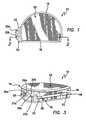
- FIG. 2is a cross-section of the device taken along line 2 - 2 of FIG. 1 .
- FIG. 3is a perspective view of the device of FIG. 1 showing the proximal region of the device.
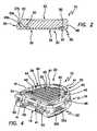
- FIG. 4is a perspective view of the device of FIG. 1 showing the distal fixation region, including the support region, of the device.
- FIG. 5is a bottom plan view of the device of FIG. 1 showing the distal fixation region of the device.
- FIG. 6is a side elevational view of the device.
- the device 10includes a curved peripheral wall or sidewall 16 and a generally straight peripheral wall or sidewall 18 , which together form, in cross-section, a generally semi-circular shape, or a generally D-shape, which approximates a resurfaced area of a bone, for example, a resurfaced area of a tibia bone, on or into which the device is to be implanted.
- Resurfacing of the tibia bone in preparation for implantation of tibial prosthesis device 10may be performed using conventional techniques, for example conventional, open surgical techniques.
- preparationmay be performed using the arthroscopic surgical devices and methods described in the co-pending U.S. provisional patent application Ser. No. 61/067,741, filed Feb. 29, 2008, entitled INSTRUMENTS AND METHOD FOR ARTHROSCOPY OF THE KNEE and commonly owned herewith, the entire disclosure of said application being incorporated herein by this specific reference.
- the device 10further comprises a distal fixation region or distal region 20 , shown perhaps most clearly in FIGS. 4 and 5 , and a proximal articulating region or proximal region 22 , shown in FIGS. 1 and 3 .
- the distal region 20is generally structured to interface with and be implanted onto or in a resurfaced region or area of a tibia bone.
- the proximal region 22 of the device 10which substantially opposes the distal region 20 , is slightly curved inwardly toward the center, for example, concave, and provides an articulating surface of the device 10 , for example, with a femur bone or a femoral prosthesis device (not shown), after the device 10 is implanted on or into a resurfaced region of a tibia bone.
- the distal region 20includes a support region 34 comprising a fixation structure, shown generally at 44 , for example, a regular or irregular fixation structure, effective to enhance fixation of the device 10 to a resurfaced region of a tibia bone relative to an identical device without the fixation structure.
- the support region 34 , and the fixation structure 44in particular, comprise a system or network or plurality of undercuts or distally extending projections 45 and channels 36 .
- the plurality of undercuts or projections 45form the channels 36 .
- some of the channels 36are positioned substantially parallel to each other and some of the channels are substantially perpendicular to each other.
- the fixation structure 44is effective so that when bone cement, for example, bone cement in a fluid state, is introduced or injected into the distal region 20 , in particular the support region 34 , for example, through the ports 32 , discussed hereinafter, while the device 10 is located in or on a resurfaced region of a tibia bone, an enhanced cement bond between the device 10 and the tibia bone is obtained.
- bone cementfor example, bone cement in a fluid state
- fixation structure 44such as the channels 36 /undercuts or projections 45 of fixation structure 44 shown in the drawings, provides the support region 34 with an increased amount of surface area, for example, relative to a substantially planar support region.
- Such increased surface areaprovides more area for the cement to bond with the device 10 and, ultimately, provides for an enhanced cement bond, for example, a cement bond of increased strength, between the device 10 and the tibia bone, for example, relative to an identical device having a planar support region.
- Bone cement useful with the present inventionmay be any suitable bone cement known to those of skill in the art.
- the bone cementmay be a grout-like material, such as polymethyl methacrylate material and/or other suitable biocompatible material known to those of skill in the art which is effective to provide long term, for example, permanent or substantially permanent, fixation of a prosthesis to a surface of a bone.
- the device 10is structured to be effective to facilitate introduction or injection and containment of bone cement during the surgical implantation procedure.
- the device 10further comprises structure for facilitating introduction of bone cement to the distal region 20 .
- the device 10comprises a port structure, shown generally at 32 , including at least one port, for example, two ports 32 a and 32 b , for facilitating introduction or injection of bone cement to the distal region 20 .
- the ports 32 a and 32 bare defined by bores extending through a surface region, for example, an angled surface region 33 , of port structure 32 , which extends outwardly and distally from the proximal region 22 of the device 10 .
- the ports 32 a and 32 binclude closed passageways defined by closed bore sidewalls 35 a and 35 b , respectively, between inlets 37 a and 37 b , respectively, and outlets 39 a and 39 b ( FIG. 5 ), respectively.
- the ports 32 a and 32 bare disposed substantially directly adjacent one another, for example, in a substantially side-by-side relationship.
- the ports 32 a and 32 bare appropriately sized and positioned to facilitate introduction or injection of a suitable bone cement in a suitable amount to the bone/implant interface during surgical implantation of the device 10 on or into a resurfaced region of a tibia bone.
- Each of the ports 32 a and 32 bhas an inlet 37 a , 37 b away from or outside of the distal region 20 , and an outlet 39 a , 39 b through which bone cement passes to be placed in the distal region 20 .
- Each of the ports 32 a and 32 bis oriented so that the closed passageway or bore 35 a , 35 b slants or slopes distally from the inlet to the outlet, for example, at an oblique or obtuse angle with respect to the support region 34 . This orientation may facilitate injection of the bone cement and/or containment of the bone cement in the desired location or locations.
- the ports 32 a and 32 b of the shown embodimentare located so that the inlets 37 a and 37 b are positioned outwardly from, and distally from the proximal region 22 of the device 10 .
- the ports 32 a and 32 bare positioned to facilitate introduction or injection of bone cement to the distal portion 20 .
- the ports 32 a and 32 bmay have any of various geometric shapes and may pass through the device 10 at an oblique or obtuse angle relative to the support region 34 , for example, as shown in FIG. 2 .
- the ports 32 a and 32 bmay be positioned generally outside of the patella-tibial articulation region of the knee joint when the device 10 is implanted or affixed to the resurfaced region of a tibia bone.
- the ports 32 a and 32 bin particular the inlets 37 a and 37 b of such ports, are located on angled surface 33 , which is positioned in proximity to the intersection of substantially straight sidewall 18 and substantially curved sidewall 16 of the device 10 .
- the angled surface 33extends outwardly from the sidewalls 16 and 18 . In one embodiment, the angled surface 33 may be joined at least partially or substantially entirely to the curved sidewall 16 .
- the device 10may comprise only one port or, alternatively, three or more ports. All such embodiments are included within the scope of the present invention.
- the introduction or injection of the bone cement or bone cement materialmay be achieved through a pressurizing syringe or similar fluid mover.
- the bone cement injectedmay be a highly viscous material or a less viscous or a more fluid material, for example, relative to the highly viscous bone cement material conventionally introduced to bond an implant to bone.
- Injecting a more fluid material, such as a material which is flowable or readily flowable at normal or atmospheric pressure under the influence of gravity,is different from injecting highly viscous material, which is not readily flowable at such conditions.
- the fluid or more fluid bone cement materialhas a viscosity (at room temperature) in a range of about 5,000 centipoise or less to about 50,000 centipoise or about 100,000 centipoise.
- the injected fluid bone cement materialhas increased effectiveness, for example, relative to highly viscous bone cement material, for example, injected highly viscous bone cement material, in filling interstitials or small regions between the prosthesis device and the bone, and/or in bonding with mating surfaces.
- the present inventionallows the surgeon to take advantage of bone cement in a more fluid state.
- Such more fluid bone cement materialfor example, more fluid bone cement material injected through one or more ports including closed passageways in the present prosthesis device, allows the pores in the bone to be filled with bonding material, as well as providing more adhesive properties to the implant itself.
- a marked or substantial increase in cement bond strength relative to conventional thumb packing techniques with “set up” bone cementhave been shown when more fluid bone cement material is injected, for example, using the prosthesis devices of the present invention.
- the distal region 20further comprises a distally extending flange or sidewall 38 .
- Flange or sidewall 38may be defined or considered as a distally extending portion of, and/or may be contiguous with, curved sidewall 16 and/or the straight sidewall 18 .
- the distally extending flange or sidewall 38may substantially entirely circumscribe the recess 40 .
- the distally extending flange or sidewall 38includes a flow control structure effective in providing for an amount, for example, a controlled or limited amount, of bone cement to flow from the distal region 20 .
- the flow control structuremay include a plurality of spaced apart, open ended notches 41 in distally extending flange 38 for receiving bone cement to form additional bonding regions between the device 10 and the resurfaced region of a tibia bone about the outer periphery of the device 10 .
- the distal region 20further includes a groove or recess 40 , which may substantially entirely circumscribe the support region 34 .
- the recess 40may be flush with and/or otherwise in communication with the notches 41 .
- This recess 40provides additional space or volume in the distal region 20 for the introduction and containment of bone cement, which may result in an enhanced cement bond between the device 10 and the tibia bone. Since the recess 40 is in communication with the notches 41 , the recess provides a supply of bone cement to be received in the notches 41 .
- recess 40is effective in controlling the placement and containment of the bone cement introduced into the distal region 20 and in reducing the risk of undesirable leakage of the bone cement from the device 10 into the joint space.
- the flow control structurein the shown embodiment, includes open sidewall groove 48 .
- Open sidewall groove 48 in the outside of sidewall 18is in communication with notches 41 and is positioned and structured to be effective to facilitate the introduction of, placement of and/or containment of bone cement used to bond the device 10 to a resurfaced region of the tibia bone by permitting bone cement, for example, a controlled or limited amount of bone cement, extruded through the notches 41 from the distal region 20 to flow around the outer periphery of the device 10 .
- the sidewall groove 48can be segmented into a plurality, that is two or more, spaced apart sidewall groove segments, for example, separated from each other by portions of the peripheral sidewall/distally extending sidewall without the sidewall groove. Such embodiment is included within the scope of the present invention.
- the flow control structure of device 10includes control bores or flow control bores 50 .
- Flow control bores 50provide additional bone cement passageways between the distal region 20 , for example, the recess 40 of the distal region, and the sidewall groove 48 .
- Such control bores 50are effective in controlling the placement of bone cement around the outer periphery of the device 10 when the device is implanted on or into a tibia bone.
- the flow control structure in accordance with the present inventionmay include any one or more of the notches 41 , the sidewall groove 48 and the flow control bores 50 .
- the device 10is a single unitary structure and has no moving parts.
- the device 10may be made of a durable, biocompatible material.
- the device 10may be made from a polymeric material, for example, any suitable polymeric material. Examples of suitable materials include ultra high molecular weight polyethylene (UHMWPE), for example, cast conforming to ASTM F75 Specification.
- UHMWPEultra high molecular weight polyethylene
- the device 10may be present in any suitable size or sizes.
Landscapes
- Health & Medical Sciences (AREA)
- Orthopedic Medicine & Surgery (AREA)
- Physical Education & Sports Medicine (AREA)
- Cardiology (AREA)
- Oral & Maxillofacial Surgery (AREA)
- Transplantation (AREA)
- Engineering & Computer Science (AREA)
- Biomedical Technology (AREA)
- Heart & Thoracic Surgery (AREA)
- Vascular Medicine (AREA)
- Life Sciences & Earth Sciences (AREA)
- Animal Behavior & Ethology (AREA)
- General Health & Medical Sciences (AREA)
- Public Health (AREA)
- Veterinary Medicine (AREA)
- Prostheses (AREA)
Abstract
Description
Claims (11)
Priority Applications (1)
| Application Number | Priority Date | Filing Date | Title |
|---|---|---|---|
| US12/393,682US8100981B2 (en) | 2008-02-29 | 2009-02-26 | Tibial prosthesis |
Applications Claiming Priority (4)
| Application Number | Priority Date | Filing Date | Title |
|---|---|---|---|
| US6774208P | 2008-02-29 | 2008-02-29 | |
| US6774108P | 2008-02-29 | 2008-02-29 | |
| US6774008P | 2008-02-29 | 2008-02-29 | |
| US12/393,682US8100981B2 (en) | 2008-02-29 | 2009-02-26 | Tibial prosthesis |
Publications (2)
| Publication Number | Publication Date |
|---|---|
| US20090228112A1 US20090228112A1 (en) | 2009-09-10 |
| US8100981B2true US8100981B2 (en) | 2012-01-24 |
Family
ID=41016467
Family Applications (2)
| Application Number | Title | Priority Date | Filing Date |
|---|---|---|---|
| US12/393,682Expired - Fee RelatedUS8100981B2 (en) | 2008-02-29 | 2009-02-26 | Tibial prosthesis |
| US12/393,658Expired - Fee RelatedUS8226727B2 (en) | 2008-02-29 | 2009-02-26 | Femoral prosthesis |
Family Applications After (1)
| Application Number | Title | Priority Date | Filing Date |
|---|---|---|---|
| US12/393,658Expired - Fee RelatedUS8226727B2 (en) | 2008-02-29 | 2009-02-26 | Femoral prosthesis |
Country Status (2)
| Country | Link |
|---|---|
| US (2) | US8100981B2 (en) |
| WO (2) | WO2009108789A1 (en) |
Cited By (6)
| Publication number | Priority date | Publication date | Assignee | Title |
|---|---|---|---|---|
| US20100217400A1 (en)* | 2009-02-24 | 2010-08-26 | Mako Surgical Corp. | Prosthetic device, method of planning bone removal for implantation of prosthetic device, and robotic system |
| US20110029090A1 (en)* | 2007-09-25 | 2011-02-03 | Depuy Products, Inc. | Prosthesis with modular extensions |
| US20140277548A1 (en)* | 2013-03-15 | 2014-09-18 | Mako Surgical Corp. | Unicondylar tibial knee implant |
| US9204967B2 (en) | 2007-09-28 | 2015-12-08 | Depuy (Ireland) | Fixed-bearing knee prosthesis having interchangeable components |
| US9278003B2 (en) | 2007-09-25 | 2016-03-08 | Depuy (Ireland) | Prosthesis for cementless fixation |
| US9937059B2 (en) | 2013-03-08 | 2018-04-10 | Stryker Corporation | Bone pads |
Families Citing this family (33)
| Publication number | Priority date | Publication date | Assignee | Title |
|---|---|---|---|---|
| US20230080207A1 (en) | 2005-02-25 | 2023-03-16 | Shoulder Innovations, Inc. | Methods and devices for less invasive glenoid replacement |
| US8778028B2 (en)* | 2005-02-25 | 2014-07-15 | Shoulder Innovations, Inc. | Methods and devices for less invasive glenoid replacement |
| US8007538B2 (en) | 2005-02-25 | 2011-08-30 | Shoulder Innovations, Llc | Shoulder implant for glenoid replacement |
| WO2009108789A1 (en)* | 2008-02-29 | 2009-09-03 | Vot, Llc | Tibial prosthesis |
| WO2010080511A1 (en) | 2008-12-18 | 2010-07-15 | 4-Web Spine, Inc. | Truss implant |
| US12279964B2 (en) | 2008-12-18 | 2025-04-22 | 4Web, Llc | Implants having bone growth promoting agents and methods of using such implants to repair bone structures |
| US8821579B2 (en)* | 2009-08-26 | 2014-09-02 | Zimmer Gmbh | Tibial component with flexible rim |
| WO2012021764A2 (en)* | 2010-08-13 | 2012-02-16 | Smith & Nephew, Inc. | Orthopaedic implants and methods |
| US8940046B2 (en)* | 2010-10-01 | 2015-01-27 | Maxx Orthopedics, Inc. | Method of implanting a prosthesis device using bone cement in liquid form |
| US20130030529A1 (en)* | 2011-07-29 | 2013-01-31 | Jessee Hunt | Implant interface system and method |
| US8771354B2 (en)* | 2011-10-26 | 2014-07-08 | George J. Picha | Hard-tissue implant |
| EP2787929B1 (en)* | 2011-12-07 | 2019-05-15 | Smith&Nephew, Inc. | Orthopedic augments having recessed pockets |
| EP2630935B1 (en)* | 2012-02-27 | 2014-12-31 | Arthrex, Inc. | Glenoid extension block |
| US12115071B2 (en) | 2012-09-25 | 2024-10-15 | 4Web, Llc | Programmable intramedullary implants and methods of using programmable intramedullary implants to repair bone structures |
| JP6310922B2 (en) | 2012-09-25 | 2018-04-11 | フォー−ウェブ・インコーポレイテッド | Programmable graft and method of using a programmable graft to repair bone structure |
| US9949837B2 (en) | 2013-03-07 | 2018-04-24 | Howmedica Osteonics Corp. | Partially porous bone implant keel |
| US20170319348A1 (en)* | 2015-08-10 | 2017-11-09 | Catalyst Orthoscience Inc. | Arthroplasty prostheses with multi-axis fixation |
| US11007063B2 (en) | 2013-03-11 | 2021-05-18 | Catalyst Orthoscience Inc. | Offset reamers |
| US10973646B2 (en) | 2013-03-11 | 2021-04-13 | Catalyst Orthoscience Inc. | Stabilized drill guide |
| KR20150130528A (en) | 2013-03-15 | 2015-11-23 | 4웹, 인코포레이티드 | Traumatic bone fracture repair systems and methods |
| US10492926B1 (en) | 2014-09-04 | 2019-12-03 | Shoulder Innovations, Inc. | Alignment guide for humeral or femoral stem replacement prostheses |
| TWI607746B (en)* | 2015-02-13 | 2017-12-11 | 花世源 | Knee joint prosthesis and tibial component and femoral component thereof |
| EP3056171B1 (en) | 2015-02-13 | 2019-03-13 | InnoLux Corporation | Knee joint prosthesis and tibial component and femoral component thereof |
| US11324606B2 (en) | 2017-03-10 | 2022-05-10 | Gary A. Zwick | Spinal interbody cage comprising a bulk interbody cage, a top face, a bottom face, pillars, and slots |
| EP3592283B1 (en) | 2017-03-10 | 2024-05-08 | Alps Holding Llc | Hard-tissue implant comprising a bulk implant, a face, pillars, slots, and at least one support member |
| EP4520302A3 (en) | 2017-04-14 | 2025-04-16 | Shoulder Innovations, Inc. | Total shoulder prosthesis having inset glenoid implant convertible from anatomic to reverse |
| US11278427B2 (en) | 2018-04-10 | 2022-03-22 | Gary A. Zick, Trustee Of The Everest Trust Uta April 20, 2017 | Spinal interbody cage comprising top and bottom faces with mesh structures, pillars and slots |
| US12138172B2 (en) | 2018-04-30 | 2024-11-12 | Shoulder Innovations, Inc. | Inset/onlay glenoid, porous coated convertible glenoid, and humeral heads with textured undersides |
| AU2020237088B2 (en) | 2019-03-11 | 2025-09-04 | Shoulder Innovations, Inc. | Total reverse shoulder systems and methods |
| USD977643S1 (en) | 2019-03-12 | 2023-02-07 | Shoulder Innovations, Inc. | Humeral stem implant |
| JP7335428B2 (en) | 2019-09-11 | 2023-08-29 | アルプス ホールディング エルエルシー | An implant comprising a first set and a second set of pillars for attaching a tendon or ligament to hard tissue |
| WO2021097438A1 (en) | 2019-11-15 | 2021-05-20 | 4Web, Inc. | Piezoelectric coated implants and methods of using piezoelectric coated implants to repair bone structures |
| EP4178496A4 (en) | 2020-07-08 | 2024-08-14 | 4Web, Inc. | Implants having bone growth promoting agents contained within biodegradable materials |
Citations (34)
| Publication number | Priority date | Publication date | Assignee | Title |
|---|---|---|---|---|
| US4166292A (en) | 1977-09-08 | 1979-09-04 | Carbomedics, Inc. | Stress reinforced artificial joint prostheses |
| US4778473A (en) | 1983-11-28 | 1988-10-18 | The University Of Michigan | Prosthesis interface surface and method of implanting |
| US4963152A (en) | 1986-10-27 | 1990-10-16 | Intermedics Orthopedics, Inc. | Asymmetric prosthetic tibial component |
| US5171276A (en) | 1990-01-08 | 1992-12-15 | Caspari Richard B | Knee joint prosthesis |
| US5266075A (en) | 1992-10-05 | 1993-11-30 | Roy Clark | Tendon threader for endosteal ligament mounting |
| US5405395A (en) | 1993-05-03 | 1995-04-11 | Wright Medical Technology, Inc. | Modular femoral implant |
| US5643273A (en) | 1995-02-17 | 1997-07-01 | Clark; Ron | ACL bone tunnel projection drill guide and method for its use |
| US5766256A (en) | 1996-01-23 | 1998-06-16 | Tornier Sa | Tibial prosthesis |
| US5954747A (en) | 1997-11-20 | 1999-09-21 | Clark; Ron | Meniscus repair anchor system |
| US6306138B1 (en) | 1997-09-24 | 2001-10-23 | Ethicon, Inc. | ACL fixation pin and method |
| US6423096B1 (en) | 1997-12-22 | 2002-07-23 | Depuy France | Knee prosthesis femoral implant and orthopaedic equipment set comprising such a femoral implant |
| US20020161448A1 (en) | 2000-07-20 | 2002-10-31 | Hayes, Jr. Daniel E. E. | Bimetal tibial component construct for knee joint prosthesis |
| US20030009232A1 (en) | 1999-03-01 | 2003-01-09 | Robert Metzger | Floating bearing knee joint prosthesis with a fixed tibial post |
| US6558389B2 (en) | 1999-11-30 | 2003-05-06 | Ron Clark | Endosteal tibial ligament fixation with adjustable tensioning |
| US6723102B2 (en) | 2001-06-14 | 2004-04-20 | Alexandria Research Technologies, Llc | Apparatus and method for minimally invasive total joint replacement |
| US20040167631A1 (en) | 2003-02-21 | 2004-08-26 | Kenny Luchesi | Fixation surface for ankle prosthesis |
| US6821300B2 (en) | 1998-03-05 | 2004-11-23 | Medidea Llc | Apparatus for positioning prosthetic component prior to cement injection |
| US20040243134A1 (en) | 2003-05-30 | 2004-12-02 | Walker Peter Stanley | Bone shaping device for knee replacement |
| US6884246B1 (en) | 1999-11-10 | 2005-04-26 | Depuy International Limited | Bone resection device |
| US6923817B2 (en) | 2001-02-27 | 2005-08-02 | Smith & Nephew, Inc. | Total knee arthroplasty systems and processes |
| US6966928B2 (en) | 1999-05-10 | 2005-11-22 | Fell Barry M | Surgically implantable knee prosthesis having keels |
| US20050283253A1 (en) | 2002-02-20 | 2005-12-22 | Coon Thomas M | Knee arthroplasty prosthesis and method |
| US20060052875A1 (en) | 2001-05-01 | 2006-03-09 | Amedica Corporation | Knee prosthesis with ceramic tibial component |
| US7083652B2 (en) | 1998-05-13 | 2006-08-01 | Depuy Products, Inc. | Tibial tray with adjustable keel |
| US7105027B2 (en) | 2002-05-08 | 2006-09-12 | Mathys Medical Ltd. | Self-aligning knee prosthesis |
| US20060235537A1 (en) | 2005-04-18 | 2006-10-19 | Accin Corporation | Unicondylar knee implant |
| US7141053B2 (en) | 2001-11-28 | 2006-11-28 | Wright Medical Technology, Inc. | Methods of minimally invasive unicompartmental knee replacement |
| US20070005142A1 (en) | 2005-06-30 | 2007-01-04 | Rhodes James M | Tibial insert and associated surgical method |
| US20070032876A1 (en) | 2005-08-05 | 2007-02-08 | Ron Clark | Knee joint prosthesis |
| US20070198022A1 (en) | 2001-05-25 | 2007-08-23 | Conformis, Inc. | Patient Selectable Joint Arthroplasty Devices and Surgical Tools |
| US20070213735A1 (en) | 2004-10-15 | 2007-09-13 | Vahid Saadat | Powered tissue modification devices and methods |
| US7297164B2 (en) | 2002-11-22 | 2007-11-20 | Zimmer Technology, Inc. | Modular knee prosthesis |
| US20070288029A1 (en) | 2005-06-10 | 2007-12-13 | Medicinelodge, Inc. | Milling system for resecting a joint articulation surface |
| US20070299532A1 (en) | 2006-06-22 | 2007-12-27 | Depuy Products, Inc. | Tibial insert having a keel including a bore formed therein |
Family Cites Families (35)
| Publication number | Priority date | Publication date | Assignee | Title |
|---|---|---|---|---|
| US3852830A (en)* | 1973-02-15 | 1974-12-10 | Richards Mfg Co | Knee prosthesis |
| US4274163A (en)* | 1979-07-16 | 1981-06-23 | The Regents Of The University Of California | Prosthetic fixation technique |
| US4711233A (en)* | 1985-06-26 | 1987-12-08 | Brown Byron L | Method and apparatus for cementing an acetabular cup to an acetabulum |
| US4888024A (en)* | 1985-11-08 | 1989-12-19 | Powlan Roy Y | Prosthetic device and method of fixation within the medullary cavity of bones |
| US4892550A (en)* | 1985-12-30 | 1990-01-09 | Huebsch Donald L | Endoprosthesis device and method |
| GB8802671D0 (en)* | 1988-02-05 | 1988-03-02 | Goodfellow J W | Orthopaedic joint components tools & methods |
| US4969888A (en)* | 1989-02-09 | 1990-11-13 | Arie Scholten | Surgical protocol for fixation of osteoporotic bone using inflatable device |
| DE3912465C1 (en)* | 1989-04-15 | 1990-11-08 | Orthoplant Endoprothetik Gmbh, 2800 Bremen, De | |
| CH680564A5 (en)* | 1989-12-07 | 1992-09-30 | Experimentelle Chirurgie Schwe | |
| DE4143453C2 (en)* | 1991-07-11 | 1997-09-11 | Haerle Anton | Centering element for bone implants |
| US5340362A (en)* | 1991-10-16 | 1994-08-23 | Carbone John J | Method and apparatus for cementing intramedullary bone prosthesis |
| GB9322327D0 (en)* | 1993-10-29 | 1993-12-15 | Howmedica | Method and apparatus for implanting an acetabular cup |
| US5702446A (en)* | 1992-11-09 | 1997-12-30 | Board Of Regents, The University Of Texas System | Bone prosthesis |
| ATE181814T1 (en)* | 1992-11-20 | 1999-07-15 | Sulzer Orthopaedie Ag | BODY FOR DISTRIBUTING BONE CEMENT FOR ANCHORING IMPLANTS |
| DE4424883A1 (en)* | 1994-07-14 | 1996-01-18 | Merck Patent Gmbh | Femoral prosthesis |
| US5976149A (en)* | 1997-02-11 | 1999-11-02 | Medidea, Llc | Method and apparatus for aligning a prosthetic element |
| US6017350A (en)* | 1997-10-03 | 2000-01-25 | Depuy Orthopaedics, Inc. | Pressurizer apparatus |
| US6500208B1 (en)* | 1998-10-16 | 2002-12-31 | Biomet, Inc. | Nonmodular joint prosthesis convertible in vivo to a modular prosthesis |
| US7488320B2 (en)* | 2001-11-01 | 2009-02-10 | Renova Orthopedics, Llc | Orthopaedic implant fixation using an in-situ formed anchor |
| JP2003153924A (en)* | 2001-11-21 | 2003-05-27 | Tomihisa Koshino | Stem of perforated prosthetic hip joint |
| US6979336B2 (en)* | 2002-03-26 | 2005-12-27 | Depuy Orthopaedics, Inc. | System and method for delivering biological materials to a prosthesis implantation site |
| US6827739B2 (en)* | 2002-08-26 | 2004-12-07 | Zimmer Technology, Inc. | Easily assembled provisional orthopaedic implant |
| US20040153087A1 (en)* | 2003-02-04 | 2004-08-05 | Sanford Adam H. | Provisional orthopedic implant with removable guide |
| US6916324B2 (en)* | 2003-02-04 | 2005-07-12 | Zimmer Technology, Inc. | Provisional orthopedic prosthesis for partially resected bone |
| US20050137708A1 (en)* | 2003-12-23 | 2005-06-23 | Ron Clark | Device and method of arthroscopic knee joint resurfacing |
| JP4510030B2 (en)* | 2004-01-12 | 2010-07-21 | デピュイ・プロダクツ・インコーポレイテッド | System and method for splitting and replacing a knee |
| US7211113B2 (en)* | 2004-05-18 | 2007-05-01 | Lev Zelener | Hip prosthesis |
| US7530982B1 (en)* | 2004-10-07 | 2009-05-12 | Biomet Manufacturing Corp. | Composite allograft formation instrument |
| NL1032851C2 (en)* | 2006-11-10 | 2008-05-14 | Fondel Finance B V | Kit and method for fixing a prosthesis or part thereof and / or filling bony defects. |
| US7842095B2 (en)* | 2007-09-11 | 2010-11-30 | Howmedica Osteonics Corp. | Antibiotic bone cement spacer |
| US8317869B2 (en)* | 2008-02-06 | 2012-11-27 | Exactech, Inc. | Femoral component of knee prosthesis, the femoral component having anterior/posterior claw(s) for digging into bone and/or a raised rib with a bulbous terminus |
| WO2009108789A1 (en)* | 2008-02-29 | 2009-09-03 | Vot, Llc | Tibial prosthesis |
| US20090299373A1 (en)* | 2008-05-30 | 2009-12-03 | Cook Incorporated | Kyphoplasty banded balloon catheter |
| AU2009291646B2 (en)* | 2008-09-12 | 2014-11-27 | Exactech, Inc. | Systems and methods relating to a knee prosthesis capable of conversion from a cruciate retaining type prosthesis to a posterior stablizing type prosthesis |
| US8454706B2 (en)* | 2009-02-25 | 2013-06-04 | Brian C. de Beaubien | Antibiotic delivery system and method for treating an infected synovial joint during re-implantation of an orthopedic prosthesis |
- 2009
- 2009-02-26WOPCT/US2009/035304patent/WO2009108789A1/enactiveApplication Filing
- 2009-02-26USUS12/393,682patent/US8100981B2/ennot_activeExpired - Fee Related
- 2009-02-26WOPCT/US2009/035301patent/WO2009111266A2/enactiveApplication Filing
- 2009-02-26USUS12/393,658patent/US8226727B2/ennot_activeExpired - Fee Related
Patent Citations (40)
| Publication number | Priority date | Publication date | Assignee | Title |
|---|---|---|---|---|
| US4166292A (en) | 1977-09-08 | 1979-09-04 | Carbomedics, Inc. | Stress reinforced artificial joint prostheses |
| US4778473A (en) | 1983-11-28 | 1988-10-18 | The University Of Michigan | Prosthesis interface surface and method of implanting |
| US4963152A (en) | 1986-10-27 | 1990-10-16 | Intermedics Orthopedics, Inc. | Asymmetric prosthetic tibial component |
| US5336266A (en) | 1990-01-08 | 1994-08-09 | Caspari Richard B | Knee joint prosthesis |
| US5171276A (en) | 1990-01-08 | 1992-12-15 | Caspari Richard B | Knee joint prosthesis |
| US5393302A (en) | 1992-10-05 | 1995-02-28 | Clark; Ron | Process for endosteal ligament mounting |
| US5266075A (en) | 1992-10-05 | 1993-11-30 | Roy Clark | Tendon threader for endosteal ligament mounting |
| US5405395A (en) | 1993-05-03 | 1995-04-11 | Wright Medical Technology, Inc. | Modular femoral implant |
| US5643273A (en) | 1995-02-17 | 1997-07-01 | Clark; Ron | ACL bone tunnel projection drill guide and method for its use |
| US5766256A (en) | 1996-01-23 | 1998-06-16 | Tornier Sa | Tibial prosthesis |
| US6780188B2 (en) | 1997-09-24 | 2004-08-24 | Ethicon, Inc. | ACL fixation pin |
| US6306138B1 (en) | 1997-09-24 | 2001-10-23 | Ethicon, Inc. | ACL fixation pin and method |
| US5954747A (en) | 1997-11-20 | 1999-09-21 | Clark; Ron | Meniscus repair anchor system |
| US6306156B1 (en) | 1997-11-20 | 2001-10-23 | Ron Clark | Meniscus repair anchor system |
| US6423096B1 (en) | 1997-12-22 | 2002-07-23 | Depuy France | Knee prosthesis femoral implant and orthopaedic equipment set comprising such a femoral implant |
| US6821300B2 (en) | 1998-03-05 | 2004-11-23 | Medidea Llc | Apparatus for positioning prosthetic component prior to cement injection |
| US7083652B2 (en) | 1998-05-13 | 2006-08-01 | Depuy Products, Inc. | Tibial tray with adjustable keel |
| US20030009232A1 (en) | 1999-03-01 | 2003-01-09 | Robert Metzger | Floating bearing knee joint prosthesis with a fixed tibial post |
| US6966928B2 (en) | 1999-05-10 | 2005-11-22 | Fell Barry M | Surgically implantable knee prosthesis having keels |
| US6884246B1 (en) | 1999-11-10 | 2005-04-26 | Depuy International Limited | Bone resection device |
| US6558389B2 (en) | 1999-11-30 | 2003-05-06 | Ron Clark | Endosteal tibial ligament fixation with adjustable tensioning |
| US20020161448A1 (en) | 2000-07-20 | 2002-10-31 | Hayes, Jr. Daniel E. E. | Bimetal tibial component construct for knee joint prosthesis |
| US6923817B2 (en) | 2001-02-27 | 2005-08-02 | Smith & Nephew, Inc. | Total knee arthroplasty systems and processes |
| US20060052875A1 (en) | 2001-05-01 | 2006-03-09 | Amedica Corporation | Knee prosthesis with ceramic tibial component |
| US20070198022A1 (en) | 2001-05-25 | 2007-08-23 | Conformis, Inc. | Patient Selectable Joint Arthroplasty Devices and Surgical Tools |
| US6723102B2 (en) | 2001-06-14 | 2004-04-20 | Alexandria Research Technologies, Llc | Apparatus and method for minimally invasive total joint replacement |
| US7141053B2 (en) | 2001-11-28 | 2006-11-28 | Wright Medical Technology, Inc. | Methods of minimally invasive unicompartmental knee replacement |
| US20050283253A1 (en) | 2002-02-20 | 2005-12-22 | Coon Thomas M | Knee arthroplasty prosthesis and method |
| US7105027B2 (en) | 2002-05-08 | 2006-09-12 | Mathys Medical Ltd. | Self-aligning knee prosthesis |
| US7297164B2 (en) | 2002-11-22 | 2007-11-20 | Zimmer Technology, Inc. | Modular knee prosthesis |
| US20040167631A1 (en) | 2003-02-21 | 2004-08-26 | Kenny Luchesi | Fixation surface for ankle prosthesis |
| US20050192583A1 (en) | 2003-05-30 | 2005-09-01 | Walker Peter S. | Bone shaping device for knee replacement |
| US20040243134A1 (en) | 2003-05-30 | 2004-12-02 | Walker Peter Stanley | Bone shaping device for knee replacement |
| US20050192584A1 (en) | 2003-05-30 | 2005-09-01 | Walker Peter S. | Bone shaping device for knee replacement |
| US20070213735A1 (en) | 2004-10-15 | 2007-09-13 | Vahid Saadat | Powered tissue modification devices and methods |
| US20060235537A1 (en) | 2005-04-18 | 2006-10-19 | Accin Corporation | Unicondylar knee implant |
| US20070288029A1 (en) | 2005-06-10 | 2007-12-13 | Medicinelodge, Inc. | Milling system for resecting a joint articulation surface |
| US20070005142A1 (en) | 2005-06-30 | 2007-01-04 | Rhodes James M | Tibial insert and associated surgical method |
| US20070032876A1 (en) | 2005-08-05 | 2007-02-08 | Ron Clark | Knee joint prosthesis |
| US20070299532A1 (en) | 2006-06-22 | 2007-12-27 | Depuy Products, Inc. | Tibial insert having a keel including a bore formed therein |
Non-Patent Citations (3)
| Title |
|---|
| International Search Report and Written Opinion dated Jun. 2, 2009 in PCT Application No. PCT/US09/35301. |
| International Search Report and Written Opinion dated May 26, 2009 in PCT Application No. PCT/US09/35304. |
| U.S. Appl. No. 12/393,658, filed Feb. 26, 2009. |
Cited By (17)
| Publication number | Priority date | Publication date | Assignee | Title |
|---|---|---|---|---|
| US20110029090A1 (en)* | 2007-09-25 | 2011-02-03 | Depuy Products, Inc. | Prosthesis with modular extensions |
| US8632600B2 (en)* | 2007-09-25 | 2014-01-21 | Depuy (Ireland) | Prosthesis with modular extensions |
| US9278003B2 (en) | 2007-09-25 | 2016-03-08 | Depuy (Ireland) | Prosthesis for cementless fixation |
| US9398956B2 (en) | 2007-09-25 | 2016-07-26 | Depuy (Ireland) | Fixed-bearing knee prosthesis having interchangeable components |
| US9204967B2 (en) | 2007-09-28 | 2015-12-08 | Depuy (Ireland) | Fixed-bearing knee prosthesis having interchangeable components |
| US10085804B2 (en) | 2009-02-24 | 2018-10-02 | Mako Surgical Corp. | Prosthetic device, method of planning bone removal for implantation of prosthetic device, and robotic system |
| US12193767B2 (en) | 2009-02-24 | 2025-01-14 | Mako Surgical Corp. | System and method for preparing bone |
| US11877812B2 (en) | 2009-02-24 | 2024-01-23 | Mako Surgical Corp. | System and method for preparing bone |
| US11065067B2 (en) | 2009-02-24 | 2021-07-20 | Mako Surgical Corp. | System and method for preparing bone |
| US20100217400A1 (en)* | 2009-02-24 | 2010-08-26 | Mako Surgical Corp. | Prosthetic device, method of planning bone removal for implantation of prosthetic device, and robotic system |
| US10537441B2 (en) | 2013-03-08 | 2020-01-21 | Stryker Corporation | Bone pads |
| US9937059B2 (en) | 2013-03-08 | 2018-04-10 | Stryker Corporation | Bone pads |
| US11318027B2 (en) | 2013-03-08 | 2022-05-03 | Stryker Corporation | Bone pads |
| US9907658B2 (en) | 2013-03-15 | 2018-03-06 | Mako Surgical Corp. | Unicondylar tibial knee implant |
| US9744044B2 (en)* | 2013-03-15 | 2017-08-29 | Mako Surgical Corp. | Unicondylar tibial knee implant |
| US9445909B2 (en) | 2013-03-15 | 2016-09-20 | Mako Surgical Corp. | Unicondylar tibial knee implant |
| US20140277548A1 (en)* | 2013-03-15 | 2014-09-18 | Mako Surgical Corp. | Unicondylar tibial knee implant |
Also Published As
| Publication number | Publication date |
|---|---|
| US8226727B2 (en) | 2012-07-24 |
| US20090228114A1 (en) | 2009-09-10 |
| WO2009108789A1 (en) | 2009-09-03 |
| WO2009111266A3 (en) | 2009-12-30 |
| WO2009111266A2 (en) | 2009-09-11 |
| US20090228112A1 (en) | 2009-09-10 |
Similar Documents
| Publication | Publication Date | Title |
|---|---|---|
| US8100981B2 (en) | Tibial prosthesis | |
| US20210393412A1 (en) | Orthopedic augments having recessed pockets | |
| US5336266A (en) | Knee joint prosthesis | |
| US5207711A (en) | Knee joint prosthesis | |
| US5201768A (en) | Prosthesis for implant on the tibial plateau of the knee | |
| US8709091B2 (en) | Tibial insert and associated surgical method | |
| US8287545B2 (en) | Methods and apparatus for enhanced retention of prosthetic implants | |
| US7862619B2 (en) | Knee joint prosthesis | |
| US20190091032A1 (en) | Talar Ankle Implant | |
| US20230200874A1 (en) | Orthopaedic surgical instruments for direct anterior approach hip arthroplasty and methods of use |
Legal Events
| Date | Code | Title | Description |
|---|---|---|---|
| AS | Assignment | Owner name:VOT, LLC, INDIANA Free format text:ASSIGNMENT OF ASSIGNORS INTEREST;ASSIGNORS:CLARK, RON;BLAKEMORE, DAVID M.;MACK, ROSS;REEL/FRAME:022696/0621;SIGNING DATES FROM 20090404 TO 20090504 Owner name:VOT, LLC, INDIANA Free format text:ASSIGNMENT OF ASSIGNORS INTEREST;ASSIGNORS:CLARK, RON;BLAKEMORE, DAVID M.;MACK, ROSS;SIGNING DATES FROM 20090404 TO 20090504;REEL/FRAME:022696/0621 | |
| STCF | Information on status: patent grant | Free format text:PATENTED CASE | |
| AS | Assignment | Owner name:DENNIS TIPPMANN, SR. FAMILY PARTNERSHIP, LLP, INDI Free format text:ASSIGNMENT OF ASSIGNORS INTEREST;ASSIGNOR:VOT, LLC;REEL/FRAME:032252/0160 Effective date:20140115 | |
| AS | Assignment | Owner name:MAXX ORTHOPEDICS, INC., PENNSYLVANIA Free format text:ASSIGNMENT OF ASSIGNORS INTEREST;ASSIGNOR:DENNIS TIPPMANN, SR. FAMILY PARTNERSHIP, LLP;REEL/FRAME:032348/0180 Effective date:20140115 | |
| FPAY | Fee payment | Year of fee payment:4 | |
| FEPP | Fee payment procedure | Free format text:MAINTENANCE FEE REMINDER MAILED (ORIGINAL EVENT CODE: REM.); ENTITY STATUS OF PATENT OWNER: SMALL ENTITY | |
| LAPS | Lapse for failure to pay maintenance fees | Free format text:PATENT EXPIRED FOR FAILURE TO PAY MAINTENANCE FEES (ORIGINAL EVENT CODE: EXP.); ENTITY STATUS OF PATENT OWNER: SMALL ENTITY | |
| STCH | Information on status: patent discontinuation | Free format text:PATENT EXPIRED DUE TO NONPAYMENT OF MAINTENANCE FEES UNDER 37 CFR 1.362 | |
| FP | Expired due to failure to pay maintenance fee | Effective date:20200124 |