US8100959B2 - Loading device for a pulmonary implant - Google Patents
Loading device for a pulmonary implantDownload PDFInfo
- Publication number
- US8100959B2 US8100959B2US12/043,404US4340408AUS8100959B2US 8100959 B2US8100959 B2US 8100959B2US 4340408 AUS4340408 AUS 4340408AUS 8100959 B2US8100959 B2US 8100959B2
- Authority
- US
- United States
- Prior art keywords
- tubular structure
- catheter
- implant
- outer tubular
- inner tubular
- Prior art date
- Legal status (The legal status is an assumption and is not a legal conclusion. Google has not performed a legal analysis and makes no representation as to the accuracy of the status listed.)
- Active, expires
Links
- 239000007943implantSubstances0.000titleclaimsabstractdescription134
- 238000011068loading methodMethods0.000titleclaimsabstractdescription70
- 230000002685pulmonary effectEffects0.000titleclaimsdescription18
- 239000012780transparent materialSubstances0.000claimsdescription2
- 230000006835compressionEffects0.000description18
- 238000007906compressionMethods0.000description18
- 230000007246mechanismEffects0.000description6
- 210000003811fingerAnatomy0.000description5
- 238000003780insertionMethods0.000description5
- 230000037431insertionEffects0.000description5
- 230000008901benefitEffects0.000description3
- HLXZNVUGXRDIFK-UHFFFAOYSA-Nnickel titaniumChemical compound[Ti].[Ti].[Ti].[Ti].[Ti].[Ti].[Ti].[Ti].[Ti].[Ti].[Ti].[Ni].[Ni].[Ni].[Ni].[Ni].[Ni].[Ni].[Ni].[Ni].[Ni].[Ni].[Ni].[Ni].[Ni]HLXZNVUGXRDIFK-UHFFFAOYSA-N0.000description3
- 229910001000nickel titaniumInorganic materials0.000description3
- 239000000463materialSubstances0.000description2
- 238000012986modificationMethods0.000description2
- 230000004048modificationEffects0.000description2
- 230000037361pathwayEffects0.000description2
- 239000012781shape memory materialSubstances0.000description2
- 206010003598AtelectasisDiseases0.000description1
- 208000019693Lung diseaseDiseases0.000description1
- 208000007123Pulmonary AtelectasisDiseases0.000description1
- 230000015556catabolic processEffects0.000description1
- 238000006731degradation reactionMethods0.000description1
- 239000012530fluidSubstances0.000description1
- 239000011521glassSubstances0.000description1
- 238000002513implantationMethods0.000description1
- 238000007373indentationMethods0.000description1
- 230000001939inductive effectEffects0.000description1
- 239000003562lightweight materialSubstances0.000description1
- 238000000034methodMethods0.000description1
- 238000004806packaging method and processMethods0.000description1
- 238000002360preparation methodMethods0.000description1
- 230000001681protective effectEffects0.000description1
- 230000000284resting effectEffects0.000description1
- 239000007787solidSubstances0.000description1
- 230000000087stabilizing effectEffects0.000description1
- 210000003813thumbAnatomy0.000description1
- 230000032258transportEffects0.000description1
- 230000002485urinary effectEffects0.000description1
- 230000002792vascularEffects0.000description1
Images


Classifications
- A—HUMAN NECESSITIES
- A61—MEDICAL OR VETERINARY SCIENCE; HYGIENE
- A61B—DIAGNOSIS; SURGERY; IDENTIFICATION
- A61B17/00—Surgical instruments, devices or methods
- A61B17/12—Surgical instruments, devices or methods for ligaturing or otherwise compressing tubular parts of the body, e.g. blood vessels or umbilical cord
- A61B17/12022—Occluding by internal devices, e.g. balloons or releasable wires
- A61B17/12099—Occluding by internal devices, e.g. balloons or releasable wires characterised by the location of the occluder
- A61B17/12104—Occluding by internal devices, e.g. balloons or releasable wires characterised by the location of the occluder in an air passage
- A—HUMAN NECESSITIES
- A61—MEDICAL OR VETERINARY SCIENCE; HYGIENE
- A61B—DIAGNOSIS; SURGERY; IDENTIFICATION
- A61B17/00—Surgical instruments, devices or methods
- A61B17/12—Surgical instruments, devices or methods for ligaturing or otherwise compressing tubular parts of the body, e.g. blood vessels or umbilical cord
- A61B17/12022—Occluding by internal devices, e.g. balloons or releasable wires
- A61B17/12131—Occluding by internal devices, e.g. balloons or releasable wires characterised by the type of occluding device
- A61B17/12168—Occluding by internal devices, e.g. balloons or releasable wires characterised by the type of occluding device having a mesh structure
- A61B17/12172—Occluding by internal devices, e.g. balloons or releasable wires characterised by the type of occluding device having a mesh structure having a pre-set deployed three-dimensional shape
- A—HUMAN NECESSITIES
- A61—MEDICAL OR VETERINARY SCIENCE; HYGIENE
- A61F—FILTERS IMPLANTABLE INTO BLOOD VESSELS; PROSTHESES; DEVICES PROVIDING PATENCY TO, OR PREVENTING COLLAPSING OF, TUBULAR STRUCTURES OF THE BODY, e.g. STENTS; ORTHOPAEDIC, NURSING OR CONTRACEPTIVE DEVICES; FOMENTATION; TREATMENT OR PROTECTION OF EYES OR EARS; BANDAGES, DRESSINGS OR ABSORBENT PADS; FIRST-AID KITS
- A61F2/00—Filters implantable into blood vessels; Prostheses, i.e. artificial substitutes or replacements for parts of the body; Appliances for connecting them with the body; Devices providing patency to, or preventing collapsing of, tubular structures of the body, e.g. stents
- A61F2/95—Instruments specially adapted for placement or removal of stents or stent-grafts
- A61F2/9522—Means for mounting a stent or stent-graft onto or into a placement instrument
- A61F2/9525—Means for mounting a stent or stent-graft onto or into a placement instrument using a funnel
- A—HUMAN NECESSITIES
- A61—MEDICAL OR VETERINARY SCIENCE; HYGIENE
- A61B—DIAGNOSIS; SURGERY; IDENTIFICATION
- A61B17/00—Surgical instruments, devices or methods
- A61B2017/00526—Methods of manufacturing
- A61B2017/0053—Loading magazines or sutures into applying tools
- A—HUMAN NECESSITIES
- A61—MEDICAL OR VETERINARY SCIENCE; HYGIENE
- A61B—DIAGNOSIS; SURGERY; IDENTIFICATION
- A61B17/00—Surgical instruments, devices or methods
- A61B2017/00743—Type of operation; Specification of treatment sites
- A61B2017/00809—Lung operations
- A—HUMAN NECESSITIES
- A61—MEDICAL OR VETERINARY SCIENCE; HYGIENE
- A61B—DIAGNOSIS; SURGERY; IDENTIFICATION
- A61B17/00—Surgical instruments, devices or methods
- A61B2017/00831—Material properties
- A61B2017/00867—Material properties shape memory effect
- A—HUMAN NECESSITIES
- A61—MEDICAL OR VETERINARY SCIENCE; HYGIENE
- A61B—DIAGNOSIS; SURGERY; IDENTIFICATION
- A61B17/00—Surgical instruments, devices or methods
- A61B17/12—Surgical instruments, devices or methods for ligaturing or otherwise compressing tubular parts of the body, e.g. blood vessels or umbilical cord
- A61B17/12022—Occluding by internal devices, e.g. balloons or releasable wires
- A61B2017/1205—Introduction devices
- A61B2017/12054—Details concerning the detachment of the occluding device from the introduction device
- A—HUMAN NECESSITIES
- A61—MEDICAL OR VETERINARY SCIENCE; HYGIENE
- A61B—DIAGNOSIS; SURGERY; IDENTIFICATION
- A61B50/00—Containers, covers, furniture or holders specially adapted for surgical or diagnostic appliances or instruments, e.g. sterile covers
- A61B50/30—Containers specially adapted for packaging, protecting, dispensing, collecting or disposing of surgical or diagnostic appliances or instruments
- A—HUMAN NECESSITIES
- A61—MEDICAL OR VETERINARY SCIENCE; HYGIENE
- A61F—FILTERS IMPLANTABLE INTO BLOOD VESSELS; PROSTHESES; DEVICES PROVIDING PATENCY TO, OR PREVENTING COLLAPSING OF, TUBULAR STRUCTURES OF THE BODY, e.g. STENTS; ORTHOPAEDIC, NURSING OR CONTRACEPTIVE DEVICES; FOMENTATION; TREATMENT OR PROTECTION OF EYES OR EARS; BANDAGES, DRESSINGS OR ABSORBENT PADS; FIRST-AID KITS
- A61F2/00—Filters implantable into blood vessels; Prostheses, i.e. artificial substitutes or replacements for parts of the body; Appliances for connecting them with the body; Devices providing patency to, or preventing collapsing of, tubular structures of the body, e.g. stents
- A61F2/02—Prostheses implantable into the body
- A61F2/04—Hollow or tubular parts of organs, e.g. bladders, tracheae, bronchi or bile ducts
- A—HUMAN NECESSITIES
- A61—MEDICAL OR VETERINARY SCIENCE; HYGIENE
- A61F—FILTERS IMPLANTABLE INTO BLOOD VESSELS; PROSTHESES; DEVICES PROVIDING PATENCY TO, OR PREVENTING COLLAPSING OF, TUBULAR STRUCTURES OF THE BODY, e.g. STENTS; ORTHOPAEDIC, NURSING OR CONTRACEPTIVE DEVICES; FOMENTATION; TREATMENT OR PROTECTION OF EYES OR EARS; BANDAGES, DRESSINGS OR ABSORBENT PADS; FIRST-AID KITS
- A61F2/00—Filters implantable into blood vessels; Prostheses, i.e. artificial substitutes or replacements for parts of the body; Appliances for connecting them with the body; Devices providing patency to, or preventing collapsing of, tubular structures of the body, e.g. stents
- A61F2/02—Prostheses implantable into the body
- A61F2/24—Heart valves ; Vascular valves, e.g. venous valves; Heart implants, e.g. passive devices for improving the function of the native valve or the heart muscle; Transmyocardial revascularisation [TMR] devices; Valves implantable in the body
- A61F2/2427—Devices for manipulating or deploying heart valves during implantation
- A61F2/2436—Deployment by retracting a sheath
- A—HUMAN NECESSITIES
- A61—MEDICAL OR VETERINARY SCIENCE; HYGIENE
- A61F—FILTERS IMPLANTABLE INTO BLOOD VESSELS; PROSTHESES; DEVICES PROVIDING PATENCY TO, OR PREVENTING COLLAPSING OF, TUBULAR STRUCTURES OF THE BODY, e.g. STENTS; ORTHOPAEDIC, NURSING OR CONTRACEPTIVE DEVICES; FOMENTATION; TREATMENT OR PROTECTION OF EYES OR EARS; BANDAGES, DRESSINGS OR ABSORBENT PADS; FIRST-AID KITS
- A61F2/00—Filters implantable into blood vessels; Prostheses, i.e. artificial substitutes or replacements for parts of the body; Appliances for connecting them with the body; Devices providing patency to, or preventing collapsing of, tubular structures of the body, e.g. stents
- A61F2/95—Instruments specially adapted for placement or removal of stents or stent-grafts
- A61F2/9522—Means for mounting a stent or stent-graft onto or into a placement instrument
- A—HUMAN NECESSITIES
- A61—MEDICAL OR VETERINARY SCIENCE; HYGIENE
- A61F—FILTERS IMPLANTABLE INTO BLOOD VESSELS; PROSTHESES; DEVICES PROVIDING PATENCY TO, OR PREVENTING COLLAPSING OF, TUBULAR STRUCTURES OF THE BODY, e.g. STENTS; ORTHOPAEDIC, NURSING OR CONTRACEPTIVE DEVICES; FOMENTATION; TREATMENT OR PROTECTION OF EYES OR EARS; BANDAGES, DRESSINGS OR ABSORBENT PADS; FIRST-AID KITS
- A61F2/00—Filters implantable into blood vessels; Prostheses, i.e. artificial substitutes or replacements for parts of the body; Appliances for connecting them with the body; Devices providing patency to, or preventing collapsing of, tubular structures of the body, e.g. stents
- A61F2/02—Prostheses implantable into the body
- A61F2/04—Hollow or tubular parts of organs, e.g. bladders, tracheae, bronchi or bile ducts
- A61F2002/043—Bronchi
Definitions
- This inventionrelates generally to implants, and specifically to devices for loading a collapsible implant onto a delivery catheter, and more particularly for loading a collapsible pulmonary implant onto a delivery catheter.
- Collapsible self-expanding implantsare well known in the medical device field. Historical medical uses for such implants include maintaining openings in vascular, urinary, biliary, esophageal, and renal tracts, and vena cava filters. Recently, modified pulmonary implants are being contemplated for the treatment of pulmonary disorders. Some such pulmonary devices differ from conventional occlusive devices in that they are designed to constrict, block, or significantly restrict fluid flow in a pulmonary passageway, rather than maintain an opening in it.
- Self-expanding pulmonary implantsmust be compressed to enable delivery through relatively small and curved body pathways.
- a delivery devicesuch as a delivery catheter, retains the pulmonary implant in its radially compressed state as it transports the implant to a treatment site through relevant bodily passageways. There, the implant is released and expands to its non-compressed shape.
- implants that are already pre-loaded onto a cathetermight lose some of their functionality as they remain on the shelf for extended periods of time before they are used in a patient.
- the devicewould be maintained in its native state until it is ready to be used in a patient.
- the physicianshould be able to load the implant onto the delivery catheter using a simple maneuver.
- the implantshould be well protected during shipping and transfer until it is ready to be used. A simple system that would meet all the above needs would be highly desirable.
- U.S. Pat. No. 6,096,027discloses an apparatus for loading a stent onto a catheter using a flexible sleeve to encase the stent as it is pulled through a tapered passageway.
- Commonly assigned published U.S. patent application No. 20060162731 A1discloses a loading mandrel positioned within a loading body, wherein the loading mandrel is manipulated to load an occlusal stent into a wide-mouthed end of the loading body and move the occlusal stent to a narrow-mouthed end within the loading body.
- a loading deviceaccepts a flexible and self-expanding implant, as well as the distal end of a delivery catheter.
- the loading deviceguides the implant through a narrowing passage that feeds into the distal end of the catheter. As the implant passes through the narrowing passage, it is compressed to a diameter that allows the implant to be inserted into the catheter.
- a loading devicecomprises an outer tubular structure and an inner tubular structure.
- the outer tubular structurecomprises a narrowing passage configured to receive a catheter at one end and a collapsible implant at another end.
- the inner tubular structureis configured to move slidably and co-axially within the outer tubular structure.
- the inner tubular structurecomprises a carrier pin configured to move within the narrowing passage as the inner tubular structure slides into the outer tubular structure. The sliding of the inner tubular structure into the outer tubular structure causes an implant mounted on the carrier pin to collapse as the implant moves through the narrowing passage and into the distal end of a catheter.
- the outer tubular structurefurther comprises a grasper to stabilize the catheter for receipt of the collapsible implant, and the internal diameter of the inner tubular structure varies to cause the grasper to first contract and stabilize the catheter, and then expand and release the catheter, as the grasper moves into the inner tubular structure.
- the loading devicecomprises an outer shaft comprising a narrowing passage leading to an opening for receiving the distal end of a catheter, an opening for accepting a collapsible implant, and two compression members.
- the first compression memberis configured to move slidably within the outer shaft and guides the implant through the narrowing passage, thereby collapsing it.
- the second compression memberthen inserts the implant into the catheter.
- the loading devicecomprises two tubular structures with opposing narrowing inner diameters, with one tubular structure configured to move slidably over the other. Placement of an implant between the structures, followed by sliding one tubular structure over the other, causes the implant to radially compress within the two opposing narrowing cavities.
- a catheter with a slotted rodis configured to hold and pull a collapsible implant through a narrowing passage and into the distal opening of the catheter.
- the slotted rodcomprises a spring loaded ball configured to increase the grip on the implant.
- the rodcomprises a grasping or latching mechanism configured to latch onto the implant as the implant is pulled through the narrowing passage and into the catheter.
- the rodcomprises a loop wire configured to secure the implant as the implant is pulled through the narrowing passage and into the catheter.
- the loop wiremay comprise shape-memory material such as Nitinol to allow it to release the implant by increasing the slack in the loop wire.
- kitsfor distributing and storing the system components.
- the kitswill include packaging for holding the components, usually including a primary package which may be a box, pouch, cylinder, or other protective package.
- the individual system componentsare usually held within separate sterile containers within the primary package, usually being in pouches, cylinders, or the like.
- self-expanding implantsmay be preloaded within the loading device and held in their uncollapsed configuration, thus reducing the risk of damaging the elastic implant materials prior to loading and implantation.
- the kitsmay comprise instructions for use setting forth any of the loading methods described herein.
- FIGS. 1 a - 1 gshow a loading device, in accordance with a first embodiment of the present invention.
- FIG. 2shows an alternative embodiment of the loading tool according to the present invention.
- FIGS. 3 a - 3 eshow a loading tool according to yet another embodiment of the present invention.
- FIGS. 4 a - 4 eillustrate a catheter with a slotted rod configured to hold and pull on the proximal end of a compressible implant.
- FIG. 5illustrates a catheter with a rod comprising a spring loaded ball to increase the grip on a compressible implant.
- FIG. 6illustrates a catheter with a rod comprising a latch mechanism to secure and pull a compressible implant.
- FIG. 7illustrates a catheter with a rod comprising a loop wire to secure and pull an implant.
- a loading devicefor loading a collapsible pulmonary implant onto a delivery system, in preparation for delivering the implant into the pulmonary airways of a patient.
- the delivery systemmay comprise a catheter.
- Collapsible pulmonary implantsare made of memory-shape materials, such as Nitinol, and are compressed to enable delivery through relatively small and curved bodily pathways to the treatment site.
- Delivery devicessuch as catheters, retain the collapsed pulmonary implants in a radially compressed state for delivery to the treatment site, where the implant is released into the airway and regains its non-compressed shape.
- the present inventiondiscloses various embodiments of a loading device that collapses such implants and optionally inserts them onto a delivery catheter.
- the present inventionfurther discloses various embodiments of catheters comprising rods for securing and pulling a collapsible pulmonary implant through a narrowing passage and into the catheter, collapsing the implant before it enters the catheter.
- the present embodimentscan be used with any implants that are delivered bronchoscopically for inducing atelectasis. Such implants may be restrictive or occlusive in nature, or valve-based.
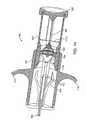
- FIGS. 1 a - 1 gillustrate a loading device 100 according to a preferred embodiment of the present invention.
- FIG. 1 ashows the assembled loading device 100 .
- An inner tubular structure 102is configured to move slidably into and out of an outer tubular structure 101 .
- the inner tubular structure 102is hereinafter also referred to as a plunger 102
- the outer tubular structure 101is hereinafter also referred to as a barrel 101 .
- the plunger 102comprises an optional cap 107 .
- a carrier pin 104may be attached to the plunger 102 itself, or alternatively attached to the cap 107 as is shown in the Figures.
- a collapsible pulmonary implant 103is mounted on the carrier pin 104 , positioned for compression through a narrowing passage and insertion into a catheter.
- One end of the barrel 101is configured to receive the implant 103 mounted on the carrier pin 104 , and the other end is configured to receive a catheter (as is shown in the additional figures below).
- the carrier pin 104guides the implant 103 through the narrowing passage 106 , compressing the implant 103 and inserting it into the opening at the distal end of the catheter.
- the barrel 101comprises optional finger rests 110 .
- Finger rests 110 and cap 107allow a user to place two fingers in the finger rests 110 and hold the loading device 100 while using the thumb or the palm of the hand to slide the plunger 102 into the barrel 101 , similar to using a syringe or a pump, as shown in FIG. 1 e.
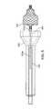
- FIG. 1 bshows an exploded view of the components of the loading device 100 , showing the barrel 101 with optional finger rests 110 , the plunger 102 , a cap 107 , a carrier pin 104 , a narrowing passage 106 , a catheter passage 109 , an optional grasper 108 , and a collapsible implant 103 .
- FIGS. 1 c and 1 dshow interior and cross-sectional views of the loading device 100 , with a catheter 105 inserted into the loading device 100 .
- the loading device 100comprises a narrowing passage 106 . Movement of the implant 103 into the narrowing passage 106 compresses the implant 103 , thereby reducing its diameter until the diameter is small enough to fit into the catheter 105 . A continuation of the same plunging motion that compresses the implant 103 also inserts it into the catheter 105 .
- the catheter 105comes to rest as it comes in contact with indentations 112 .
- a usercompresses the loading device, as shown in FIG. 1 e , thereby causing tubular structure 102 to move into tubular structure 101 .
- the loading device 100optionally comprises a grasper 108 .
- the grasper 108is configured to grasp down on an inserted catheter 105 upon application of a force, which is provided by the tapered cavity of the plunger 102 .
- This cavitycomprises a first section with a reduced internal diameter 111 a and a second section with a larger internal diameter 111 b , as depicted in FIG. 1 d.
- the grasper 108Prior to the plunger 102 sliding into the barrel 101 , the grasper 108 is in an open, released state. The sliding of the plunger 102 into the barrel 101 forces the grasper 108 through the reduced diameter section of the plunger 102 and causes the grasper 108 arms to close. As a result, the grasper 108 grasps and holds down the catheter 105 , thereby stabilizing the catheter 105 for the insertion of the compressed implant 103 during the movement of the loading device 100 . Upon moving through and exiting the reduced diameter section of the plunger 102 and entering the larger diameter section, the grasper 108 arms return to their open state, thereby releasing the loaded catheter 105 and allowing a user to remove the catheter 105 from the loading device 100 .
- FIG. 1 fshows the loading device 100 in a partially compressed state.
- the plunger 102has moved into the tubular structure 101 , and the carrier pin 104 has guided the implant 103 through the narrowing passage 106 and compressed it.
- FIG. 1 gshows the loading device 100 in a fully compressed state.
- the loading device 100is fully compressed, i.e., the plunger 102 has completed its travel from the proximal end of the barrel 101 to the distal end of the barrel 101 , the implant 103 has been inserted into the catheter 105 , and the grasper 108 has released the catheter 105 after passing through the reduced diameter section of the plunger 102 .
- the loading device 100has, in one continuous motion, grasped (stabilized) the delivery catheter 105 , loaded the implant 103 onto the catheter 105 , and released the catheter 105 when the implant 103 has been loaded. This enables the user to conveniently load an implant 103 with the least amount of effort and ensure that it is loaded properly.
- the loading device 100is configured to allow a user to visually verify that the implant 103 is loaded onto the catheter 105 .
- the plunger 102 and/or barrel 101may comprise at least partially transparent material, such as glass or plastic.
- the device 100may comprise a cut-away portion serving as a viewing port.
- the loading device 100it allows for loading the implant 103 at an accurate and predictable location within the catheter 105 . It is another advantageous aspect of the loading device 100 that it facilitates simple, straightforward, repeatable operation, providing ease of use. It is yet another advantageous aspect of the loading device 100 that it prevents damage to the implant 103 during shipping, storage, and loading operation. It is yet another advantageous aspect of the loading device 100 that it prevents the implant 103 from resting on its side over an extended period of time, thereby preventing damage to, or functional degradation of, the implant 103 .
- One of the most important advantages offered by the loading device 100is that it prevents insertion of the implant 103 onto the catheter 105 in an incorrect (i.e., reversed) distal-proximal orientation.
- the loading device 100may be made of light-weight materials, as well as an intuitive form factor, and thus making it easy it to handle.
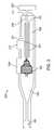
- FIG. 2shows a loading device 200 according to a second alternative embodiment of the present invention.
- Loading device 200comprises an elongate outer shaft 208 comprising a narrowing passage 206 leading to an opening 205 for receiving the distal end of a catheter (not shown).
- the loading device 200comprises a first stage compression member 207 configured to move slidably within the outer shaft 208 , and a second stage compression member 204 configured to move slidably within the first stage compression member 207 .
- the first stage compression member 207comprises a handle 201 protruding through an opening 210 on the side of the outer shaft 208 .
- the second stage compression member 204comprises a handle 202 protruding through an opening 211 of the outer shaft 208 .
- the two compression members 207 and 204are connected to each other via a tether 212 .
- the implant 103is inserted into through an opening 209 into the loading device 200 , and the distal tip of a catheter 105 is inserted into the opening 205 .
- the catheter's tipis secured to the loading device 200 prior to insertion of the implant 103 .
- a useruses handle 201 to slide the first stage compression member 207 towards the narrowing passage 206 .
- the first stage compression member 207guides the implant 103 through the narrowing passage 206 , thereby compressing the implant 103 .
- the implant 103is sufficiently compressed to allow the second stage compression member 204 to insert the implant 103 into the catheter 105 . Since the two compression members are tethered together, the second stage compression member 204 follows as the first stage compression member 207 completes its range of motion.
- the useruses the handle 202 to slide the second stage compression member 204 forward, guiding the now compressed implant 103 through the remainder of the narrowing passage 206 and into the opening at the distal end of the catheter 105 .
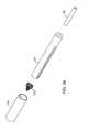
- FIGS. 3 a - 3 eshow a loading device 300 according to a third alternative embodiment of the present invention.
- the loading device 300comprises two tubular structures 301 and 302 , with tubular structure 302 configured to move slidably over tubular structure 301 .
- the tubular structures 301 and 302each have a narrowing inner cavity, with opposing directions of narrowing, as can be seen in FIG. 3 b .
- Tubular structure 301has an opening for insertion of a catheter 105 . Placement of the implant 103 between tubular structures 301 and 302 , followed by the sliding of tubular structure 302 over tubular structure 301 , causes the implant 103 to radially compress within the two opposing narrowing cavities and slide into the catheter 105 .
- FIG. 3 cshows a cross-sectional view of the separated tubular structures 301 and 302 .
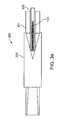
- FIGS. 4 a - 4 e , 5 , 6 and 7show catheter 105 comprising members for loading an uncompressed implant 103 onto the catheter 105 , in accordance with embodiments of the present invention.
- the catheter 105comprises a lumen or sheath, and a member within the lumen or sheath that extends distally out of the catheter 105 and attaches itself to an uncompressed implant 103 , pulls the implant 103 through a narrowing passage to compress the implant 103 , and then continues to pull the now compressed implant 103 into the catheter 105 .
- FIGS. 4 a - 4 eillustrate a catheter 105 with a slotted rod 601 configured to hold the proximal end (such as a bushing) of a compressible implant 103 , in accordance with an embodiment of the present invention.
- the catheteris inserted through a narrowing passage 602 .
- the rodmay be a hypotube, a coil, a solid wire, or any other such element that can be rigid.
- the slotted rod 601is extended distally out of its encasing catheter 105 .
- the uncompressed implant 103is placed within the slot.
- the slotted rod 601then pulls the implant 103 through the narrowing passage 602 and compresses it (not shown) to a diameter that is small enough to be inserted into the internal lumen of the catheter 105 .
- the collapsed implant 103is pulled into the catheter 105 , as shown in FIG. 4 c.
- the implant 103can be released from the catheter 105 by extending the rod 601 distally out of the catheter 105 , or alternatively by pulling the catheter lumen or sheath back to expose the rod 601 . Referring to FIGS. 4 d and 4 e , once the implant 103 has been deployed into the bronchial passageway of a patient, the user can twist or turn the rod 601 and disengage the implant 103 .
- the rodmay comprise a mechanism for more tightly gripping the implant 103 .
- a rod 603is shown comprising a spring 603 a and a spring loaded ball 603 b to increase the grip on the implant 103 .
- the slotted rod 603is pushed out of its catheter (not shown).
- the bushing of the implant 103is placed within the slot and the spring loaded ball 603 b exerts a gripping pressure against the implant 103 , holding it tightly in place.
- the implant 103is then pulled into the narrowing passage 602 and compressed to a diameter smaller than that of the internal lumen of the catheter (not shown) and further pulled into the catheter.
- the implant 103can be released again from the catheter by pushing the rod 603 out of the catheter, or alternatively by pulling the catheter lumen or sheath back to expose the rod 603 .
- the usercan twist and turn the rod 603 to disengage the implant 103 .
- the rodmay comprise an attachment mechanism such as a latch mechanism to latch onto the implant 103 .
- the rod 604comprises a latch 604 a and is extended distally out of its encasing catheter 105 .
- the bushing of the implant 103is placed within the latch 604 a and locked into place.
- the implant 103is then pulled through the narrowing passage 602 and compressed to a diameter smaller than that of the internal lumen of the catheter 105 .
- the implant 103can be released again from the catheter 105 by pushing the rod 604 out of the catheter 105 (or alternatively by pulling the catheter lumen or sheath back to expose the rod 604 ) and releasing the latch 604 a .
- releasing the latch 604 acauses the rod 604 to disengage from and release the implant 103 .
- the rodmay comprise a loop wire as an attachment mechanism to secure the implant 103 to the rod.
- the rod 605comprises a loop wire 605 a that protrudes out of its encasing catheter 105 and loops around the bushing of the implant 103 , pulling the implant 103 into the narrowing passage 602 and compressing it to a diameter smaller than that of the internal lumen of the catheter 105 .
- the loop wire 605 amay comprise shape memory material such as Nitinol to allow it to release the implant 103 by increasing the slack in the loop wire 605 a.
Landscapes
- Health & Medical Sciences (AREA)
- Life Sciences & Earth Sciences (AREA)
- Surgery (AREA)
- Engineering & Computer Science (AREA)
- Biomedical Technology (AREA)
- Animal Behavior & Ethology (AREA)
- Veterinary Medicine (AREA)
- Vascular Medicine (AREA)
- Public Health (AREA)
- Heart & Thoracic Surgery (AREA)
- General Health & Medical Sciences (AREA)
- Molecular Biology (AREA)
- Medical Informatics (AREA)
- Nuclear Medicine, Radiotherapy & Molecular Imaging (AREA)
- Reproductive Health (AREA)
- Cardiology (AREA)
- Oral & Maxillofacial Surgery (AREA)
- Transplantation (AREA)
- Media Introduction/Drainage Providing Device (AREA)
- Prostheses (AREA)
Abstract
Description
Claims (7)
Priority Applications (4)
| Application Number | Priority Date | Filing Date | Title |
|---|---|---|---|
| US12/043,404US8100959B2 (en) | 2007-03-09 | 2008-03-06 | Loading device for a pulmonary implant |
| PCT/US2008/056289WO2008112574A2 (en) | 2007-03-09 | 2008-03-07 | Loading a device for a pulmonary implant |
| EP08743733.1AEP2120821B1 (en) | 2007-03-09 | 2008-03-07 | Loading a device for a pulmonary implant |
| JP2009553704AJP5528818B2 (en) | 2007-03-09 | 2008-03-07 | Lung graft loading device |
Applications Claiming Priority (2)
| Application Number | Priority Date | Filing Date | Title |
|---|---|---|---|
| US89394007P | 2007-03-09 | 2007-03-09 | |
| US12/043,404US8100959B2 (en) | 2007-03-09 | 2008-03-06 | Loading device for a pulmonary implant |
Publications (2)
| Publication Number | Publication Date |
|---|---|
| US20080221703A1 US20080221703A1 (en) | 2008-09-11 |
| US8100959B2true US8100959B2 (en) | 2012-01-24 |
Family
ID=39742462
Family Applications (1)
| Application Number | Title | Priority Date | Filing Date |
|---|---|---|---|
| US12/043,404Active2029-10-11US8100959B2 (en) | 2007-03-09 | 2008-03-06 | Loading device for a pulmonary implant |
Country Status (4)
| Country | Link |
|---|---|
| US (1) | US8100959B2 (en) |
| EP (1) | EP2120821B1 (en) |
| JP (1) | JP5528818B2 (en) |
| WO (1) | WO2008112574A2 (en) |
Cited By (3)
| Publication number | Priority date | Publication date | Assignee | Title |
|---|---|---|---|---|
| US20090143852A1 (en)* | 2007-12-04 | 2009-06-04 | Chambers Sean D | Storage and loading system for implantable medical devices |
| US20150320539A1 (en)* | 2012-06-28 | 2015-11-12 | Qvanteq Ag | Packaging and transfer system for an implant application |
| US20210186692A1 (en)* | 2019-12-20 | 2021-06-24 | Medtronic Vascular, Inc. | Hydraulic crimping device |
Families Citing this family (47)
| Publication number | Priority date | Publication date | Assignee | Title |
|---|---|---|---|---|
| DE102005003632A1 (en) | 2005-01-20 | 2006-08-17 | Fraunhofer-Gesellschaft zur Förderung der angewandten Forschung e.V. | Catheter for the transvascular implantation of heart valve prostheses |
| US7896915B2 (en) | 2007-04-13 | 2011-03-01 | Jenavalve Technology, Inc. | Medical device for treating a heart valve insufficiency |
| BR112012021347A2 (en) | 2008-02-26 | 2019-09-24 | Jenavalve Tecnology Inc | stent for positioning and anchoring a valve prosthesis at an implantation site in a patient's heart |
| US9044318B2 (en) | 2008-02-26 | 2015-06-02 | Jenavalve Technology Gmbh | Stent for the positioning and anchoring of a valvular prosthesis |
| EP2358280A4 (en)* | 2008-12-19 | 2015-05-06 | Covidien Lp | Method and apparatus for storage and/or introduction of implant for hollow anatomical structure |
| JP2013500792A (en)* | 2009-07-30 | 2013-01-10 | ストライカー コーポレイション | Stent delivery system |
| US8579964B2 (en) | 2010-05-05 | 2013-11-12 | Neovasc Inc. | Transcatheter mitral valve prosthesis |
| US10856978B2 (en) | 2010-05-20 | 2020-12-08 | Jenavalve Technology, Inc. | Catheter system |
| WO2011147849A1 (en) | 2010-05-25 | 2011-12-01 | Jenavalve Technology Inc. | Prosthetic heart valve and transcatheter delivered endoprosthesis comprising a prosthetic heart valve and a stent |
| WO2012036742A2 (en) | 2010-09-17 | 2012-03-22 | St. Jude Medical, Cardiology Division, Inc. | Assembly and method for loading a self-expanding collapsible heart valve |
| WO2012106491A1 (en)* | 2011-02-02 | 2012-08-09 | St. Jude Medical, Inc. | System and method for loading a collapsile heart valve into a delivery device |
| US9155619B2 (en)* | 2011-02-25 | 2015-10-13 | Edwards Lifesciences Corporation | Prosthetic heart valve delivery apparatus |
| US9308087B2 (en) | 2011-04-28 | 2016-04-12 | Neovasc Tiara Inc. | Sequentially deployed transcatheter mitral valve prosthesis |
| US9554897B2 (en) | 2011-04-28 | 2017-01-31 | Neovasc Tiara Inc. | Methods and apparatus for engaging a valve prosthesis with tissue |
| US8893370B2 (en) | 2011-07-28 | 2014-11-25 | St. Jude Medical, Cardiology Division, Inc. | System for loading a collapsible heart valve |
| BR112014002002A2 (en) | 2011-07-28 | 2017-02-21 | St Jude Medical Cardiology Div Inc | unit and method for charging a self-expanding prosthetic device to a delivery device |
| WO2013044267A1 (en) | 2011-09-23 | 2013-03-28 | Pulmonx, Inc. | Implant loading device and system |
| EP2760374A1 (en)* | 2011-09-30 | 2014-08-06 | Jenavalve Technology INC. | System and method for loading a stent into a medical delivery system |
| US9510947B2 (en) | 2011-10-21 | 2016-12-06 | Jenavalve Technology, Inc. | Catheter system for introducing an expandable heart valve stent into the body of a patient |
| EP2849678B1 (en) | 2012-05-16 | 2022-08-10 | JenaValve Technology, Inc. | Catheter delivery system for introducing an expandable heart valve prosthesis and medical device for the treatment of a heart valve defect |
| US9345573B2 (en) | 2012-05-30 | 2016-05-24 | Neovasc Tiara Inc. | Methods and apparatus for loading a prosthesis onto a delivery system |
| US20140277341A1 (en)* | 2013-03-15 | 2014-09-18 | Cook Medical Technologies Llc | Wireless medical device release mechanism |
| US9572665B2 (en) | 2013-04-04 | 2017-02-21 | Neovasc Tiara Inc. | Methods and apparatus for delivering a prosthetic valve to a beating heart |
| CN105491978A (en) | 2013-08-30 | 2016-04-13 | 耶拿阀门科技股份有限公司 | Radially collapsible frame for a prosthetic valve and method for manufacturing such a frame |
| US10182910B2 (en)* | 2013-10-23 | 2019-01-22 | Biotronik Ag | Method for fitting an implant to a catheter |
| US10925611B2 (en) | 2015-01-20 | 2021-02-23 | Neurogami Medical, Inc. | Packaging for surgical implant |
| EP3270825B1 (en) | 2015-03-20 | 2020-04-22 | JenaValve Technology, Inc. | Heart valve prosthesis delivery system |
| US10709555B2 (en) | 2015-05-01 | 2020-07-14 | Jenavalve Technology, Inc. | Device and method with reduced pacemaker rate in heart valve replacement |
| CA3007660A1 (en) | 2015-12-15 | 2017-06-22 | Neovasc Tiara Inc. | Transseptal delivery system |
| US10433952B2 (en) | 2016-01-29 | 2019-10-08 | Neovasc Tiara Inc. | Prosthetic valve for avoiding obstruction of outflow |
| US10926093B2 (en) | 2016-05-05 | 2021-02-23 | Pacesetter, Inc. | System and method for loading a leadless pacemaker onto a catheter-based delivery system |
| WO2017195125A1 (en) | 2016-05-13 | 2017-11-16 | Jenavalve Technology, Inc. | Heart valve prosthesis delivery system and method for delivery of heart valve prosthesis with introducer sheath and loading system |
| US10576099B2 (en) | 2016-10-21 | 2020-03-03 | Covidien Lp | Injectable scaffold for treatment of intracranial aneurysms and related technology |
| CA3042588A1 (en) | 2016-11-21 | 2018-05-24 | Neovasc Tiara Inc. | Methods and systems for rapid retraction of a transcatheter heart valve delivery system |
| WO2018138658A1 (en) | 2017-01-27 | 2018-08-02 | Jenavalve Technology, Inc. | Heart valve mimicry |
| EP3654883A1 (en) | 2017-07-18 | 2020-05-27 | St. Jude Medical, Cardiology Division, Inc. | Flushable loading base |
| CA3073834A1 (en) | 2017-08-25 | 2019-02-28 | Neovasc Tiara Inc. | Sequentially deployed transcatheter mitral valve prosthesis |
| US12053207B2 (en) | 2018-03-21 | 2024-08-06 | Pacesetter, Inc. | Loading tool for a biostimulator |
| CN113271890B (en) | 2018-11-08 | 2024-08-30 | 内奥瓦斯克迪亚拉公司 | Ventricular deployment of transcatheter mitral valve prosthesis |
| CA3132873A1 (en) | 2019-03-08 | 2020-09-17 | Neovasc Tiara Inc. | Retrievable prosthesis delivery system |
| CA3135753C (en) | 2019-04-01 | 2023-10-24 | Neovasc Tiara Inc. | Controllably deployable prosthetic valve |
| US11491006B2 (en) | 2019-04-10 | 2022-11-08 | Neovasc Tiara Inc. | Prosthetic valve with natural blood flow |
| US20220211481A1 (en)* | 2019-04-22 | 2022-07-07 | Eolo Medical Inc. | Devices for the treatment of pulmonary disorders with implantable valves |
| US11779742B2 (en) | 2019-05-20 | 2023-10-10 | Neovasc Tiara Inc. | Introducer with hemostasis mechanism |
| JP7520897B2 (en) | 2019-06-20 | 2024-07-23 | ニオバスク ティアラ インコーポレイテッド | Thin prosthetic mitral valve |
| WO2021092618A1 (en) | 2019-11-04 | 2021-05-14 | Covidien Lp | Devices, systems, and methods for treatment of intracranial aneurysms |
| WO2024102411A1 (en) | 2022-11-09 | 2024-05-16 | Jenavalve Technology, Inc. | Catheter system for sequential deployment of an expandable implant |
Citations (66)
| Publication number | Priority date | Publication date | Assignee | Title |
|---|---|---|---|---|
| US3322126A (en) | 1963-04-19 | 1967-05-30 | Willy Rusch Fa | Endotracheal catheter |
| US3498286A (en) | 1966-09-21 | 1970-03-03 | American Optical Corp | Catheters |
| US3542026A (en) | 1968-07-23 | 1970-11-24 | Billy M Bledsoe | Thoracostomy device |
| US3669098A (en) | 1968-10-05 | 1972-06-13 | Olympus Optical Co | Endotracheal tube |
| US3677262A (en) | 1970-07-23 | 1972-07-18 | Henry J Zukowski | Surgical instrument illuminating endotracheal tube inserter |
| US3776222A (en) | 1971-12-23 | 1973-12-04 | Lurosso A | Fiber optic entubator and method of entubation of the trachea through the nasopharynx |
| US3866599A (en) | 1972-01-21 | 1975-02-18 | Univ Washington | Fiberoptic catheter |
| US3913568A (en) | 1973-01-22 | 1975-10-21 | American Optical Corp | Nasopharyngoscope |
| US4041936A (en) | 1975-04-23 | 1977-08-16 | Medical Engineering Corporation | Bronchoscopy tube |
| US4327721A (en) | 1978-07-07 | 1982-05-04 | George Hanover | Endotracheal tube with topical agent delivery system and method of using the same |
| US4327720A (en) | 1979-01-22 | 1982-05-04 | Bronson Paul A | Esophageal-endotracheal airway |
| US4453545A (en) | 1981-05-07 | 1984-06-12 | Hiroshi Inoue | Endotracheal tube with movable endobronchial blocker for one-lung anesthesia |
| US4468216A (en) | 1982-05-20 | 1984-08-28 | Rudolph Muto | Irrigation suction catheter |
| US4567882A (en) | 1982-12-06 | 1986-02-04 | Vanderbilt University | Method for locating the illuminated tip of an endotracheal tube |
| US4716896A (en) | 1986-08-01 | 1988-01-05 | Ackrad Laboratories | Bronchial catheter |
| US4742819A (en) | 1987-03-23 | 1988-05-10 | George Gordon P | Intubating scope with camera and screen |
| US4784133A (en) | 1987-01-28 | 1988-11-15 | Mackin Robert A | Working well balloon angioscope and method |
| US4819664A (en) | 1984-11-15 | 1989-04-11 | Stefano Nazari | Device for selective bronchial intubation and separate lung ventilation, particularly during anesthesia, intensive therapy and reanimation |
| US4846153A (en) | 1988-06-10 | 1989-07-11 | George Berci | Intubating video endoscope |
| US4850371A (en) | 1988-06-13 | 1989-07-25 | Broadhurst John H | Novel endotracheal tube and mass spectrometer |
| US4862874A (en) | 1987-06-10 | 1989-09-05 | Kellner Hans Joerg | Endoscope for removal of thrombi from pulmonary arterial vessels |
| US4896941A (en) | 1985-04-27 | 1990-01-30 | Doryokuro Kakunenryo Kaihatsu Jigyodan | Image-transmitting fiber |
| US4949716A (en) | 1988-10-31 | 1990-08-21 | Medical Devices, Inc. | Nasal intubation adjunct |
| US4955375A (en) | 1989-01-23 | 1990-09-11 | Ricardo Martinez | Endotracheal tube with channel for delivering drugs |
| US4958932A (en) | 1988-08-18 | 1990-09-25 | Mcdonnell Douglas Corporation | Optical measuring apparatus |
| US4961738A (en) | 1987-01-28 | 1990-10-09 | Mackin Robert A | Angioplasty catheter with illumination and visualization within angioplasty balloon |
| US4976710A (en) | 1987-01-28 | 1990-12-11 | Mackin Robert A | Working well balloon method |
| US5056529A (en) | 1990-04-03 | 1991-10-15 | Groot William J De | Apparatus and method for performing a transbroncheal biopsy |
| WO1992010971A1 (en) | 1990-12-21 | 1992-07-09 | Ballard Medical Products | Bronchoalveolar lavage catheter |
| US5143062A (en) | 1990-10-26 | 1992-09-01 | Mallinckrodt Medical, Inc. | Endotracheal tube having irrigation means |
| US5146916A (en) | 1990-01-05 | 1992-09-15 | Catalani Angelo S | Endotracheal tube incorporating a drug-irrigation device |
| US5285778A (en) | 1991-04-19 | 1994-02-15 | Mackin Robert A | Endotracheal tube wih fibers optic illumination and viewing and auxiliary tube |
| US5309903A (en) | 1989-12-12 | 1994-05-10 | Burroughs Wellcome Co. | Method for administering surfactant to the lungs while concurrently providing one-lung ventilation |
| US5331947A (en) | 1992-05-01 | 1994-07-26 | Shturman Cardiology Systems, Inc. | Inflatable sheath for introduction of ultrasonic catheter through the lumen of a fiber optic endoscope |
| US5361753A (en) | 1992-07-07 | 1994-11-08 | Deutsche Aerospace Ag | Method of measuring and regulating the pressure in the sealing cuff of a tracheal tube and apparatus for implementing the method |
| WO1995033506A1 (en) | 1994-06-04 | 1995-12-14 | Archibald Ian Jeremy Brain | A fibreoptic intubating laryngeal mask airway |
| US5477851A (en) | 1995-01-26 | 1995-12-26 | Callaghan; Eric B. | Laryngeal mask assembly and method for removing same |
| US5499625A (en) | 1994-01-27 | 1996-03-19 | The Kendall Company | Esophageal-tracheal double lumen airway |
| US5598840A (en) | 1995-03-17 | 1997-02-04 | Sorenson Critical Care, Inc. | Apparatus and method for ventilation and aspiration |
| US5642730A (en) | 1994-06-17 | 1997-07-01 | Trudell Medical Limited | Catheter system for delivery of aerosolized medicine for use with pressurized propellant canister |
| US5645519A (en) | 1994-03-18 | 1997-07-08 | Jai S. Lee | Endoscopic instrument for controlled introduction of tubular members in the body and methods therefor |
| US5653231A (en) | 1995-11-28 | 1997-08-05 | Medcare Medical Group, Inc. | Tracheostomy length single use suction catheter |
| US5660175A (en) | 1995-08-21 | 1997-08-26 | Dayal; Bimal | Endotracheal device |
| US5682880A (en) | 1996-07-26 | 1997-11-04 | Brain; Archibald Ian Jeremy | Laryngeal-mask airway with guide element, stiffener, and fiberoptic access |
| US5707352A (en) | 1989-08-28 | 1998-01-13 | Alliance Pharmaceutical Corp. | Pulmonary delivery of therapeutic agent |
| US5725519A (en)* | 1996-09-30 | 1998-03-10 | Medtronic Instent Israel Ltd. | Stent loading device for a balloon catheter |
| US5752921A (en) | 1996-01-11 | 1998-05-19 | Korr Medical Technologies, Inc. | Method and apparatus for determining tracheal pressure |
| US5830222A (en) | 1995-10-13 | 1998-11-03 | Transvascular, Inc. | Device, system and method for intersititial transvascular intervention |
| WO1998048706A1 (en) | 1997-04-30 | 1998-11-05 | Bradford Hospitals Nhs Trust | Occlusion device |
| US5840064A (en) | 1994-03-31 | 1998-11-24 | United States Surgical Corporation | Method and apparatus for treating stenosis or other constriction in a bodily conduit |
| US5957949A (en) | 1997-05-01 | 1999-09-28 | World Medical Manufacturing Corp. | Percutaneous placement valve stent |
| US5974652A (en) | 1998-05-05 | 1999-11-02 | Advanced Cardiovascular Systems, Inc. | Method and apparatus for uniformly crimping a stent onto a catheter |
| US5992000A (en)* | 1997-10-16 | 1999-11-30 | Scimed Life Systems, Inc. | Stent crimper |
| US6068635A (en)* | 1998-03-04 | 2000-05-30 | Schneider (Usa) Inc | Device for introducing an endoprosthesis into a catheter shaft |
| US6096027A (en)* | 1998-09-30 | 2000-08-01 | Impra, Inc., A Subsidiary Of C.R. Bard, Inc. | Bag enclosed stent loading apparatus |
| US6132458A (en)* | 1998-05-15 | 2000-10-17 | American Medical Systems, Inc. | Method and device for loading a stent |
| US6165209A (en)* | 1997-12-15 | 2000-12-26 | Prolifix Medical, Inc. | Vascular stent for reduction of restenosis |
| US6287290B1 (en) | 1999-07-02 | 2001-09-11 | Pulmonx | Methods, systems, and kits for lung volume reduction |
| US6398775B1 (en) | 1999-10-21 | 2002-06-04 | Pulmonx | Apparatus and method for isolated lung access |
| US6527761B1 (en) | 2000-10-27 | 2003-03-04 | Pulmonx, Inc. | Methods and devices for obstructing and aspirating lung tissue segments |
| US20030083730A1 (en)* | 2001-10-25 | 2003-05-01 | Scimed Life Systems, Inc. | Loading cartridge for self-expanding stent |
| US6585639B1 (en) | 2000-10-27 | 2003-07-01 | Pulmonx | Sheath and method for reconfiguring lung viewing scope |
| US20030225445A1 (en)* | 2002-05-14 | 2003-12-04 | Derus Patricia M. | Surgical stent delivery devices and methods |
| US20060162731A1 (en)* | 2004-11-16 | 2006-07-27 | Pulmonx | Pulmonary occlusal stent delivery catheter, loading system and methods of use |
| US20070270937A1 (en)* | 2006-05-19 | 2007-11-22 | Boston Scientific Scimed, Inc. | Apparatus and method for loading and delivering a stent |
| US7780697B2 (en)* | 1997-11-07 | 2010-08-24 | Salviac Limited | Embolic protection system |
Family Cites Families (3)
| Publication number | Priority date | Publication date | Assignee | Title |
|---|---|---|---|---|
| DE3736680C1 (en)* | 1987-10-29 | 1988-10-27 | Didier Werke Ag | Process for the production of carbon-bonded refractory molded parts |
| US5984944A (en)* | 1997-09-12 | 1999-11-16 | B. Braun Medical, Inc. | Introducer for an expandable vascular occlusion device |
| US20040210248A1 (en)* | 2003-03-12 | 2004-10-21 | Spiration, Inc. | Apparatus, method and assembly for delivery of intra-bronchial devices |
- 2008
- 2008-03-06USUS12/043,404patent/US8100959B2/enactiveActive
- 2008-03-07JPJP2009553704Apatent/JP5528818B2/enactiveActive
- 2008-03-07EPEP08743733.1Apatent/EP2120821B1/enactiveActive
- 2008-03-07WOPCT/US2008/056289patent/WO2008112574A2/enactiveApplication Filing
Patent Citations (68)
| Publication number | Priority date | Publication date | Assignee | Title |
|---|---|---|---|---|
| US3322126A (en) | 1963-04-19 | 1967-05-30 | Willy Rusch Fa | Endotracheal catheter |
| US3498286A (en) | 1966-09-21 | 1970-03-03 | American Optical Corp | Catheters |
| US3542026A (en) | 1968-07-23 | 1970-11-24 | Billy M Bledsoe | Thoracostomy device |
| US3669098A (en) | 1968-10-05 | 1972-06-13 | Olympus Optical Co | Endotracheal tube |
| US3677262A (en) | 1970-07-23 | 1972-07-18 | Henry J Zukowski | Surgical instrument illuminating endotracheal tube inserter |
| US3776222A (en) | 1971-12-23 | 1973-12-04 | Lurosso A | Fiber optic entubator and method of entubation of the trachea through the nasopharynx |
| US3866599A (en) | 1972-01-21 | 1975-02-18 | Univ Washington | Fiberoptic catheter |
| US3913568A (en) | 1973-01-22 | 1975-10-21 | American Optical Corp | Nasopharyngoscope |
| US4041936A (en) | 1975-04-23 | 1977-08-16 | Medical Engineering Corporation | Bronchoscopy tube |
| US4327721A (en) | 1978-07-07 | 1982-05-04 | George Hanover | Endotracheal tube with topical agent delivery system and method of using the same |
| US4327720A (en) | 1979-01-22 | 1982-05-04 | Bronson Paul A | Esophageal-endotracheal airway |
| US4453545A (en) | 1981-05-07 | 1984-06-12 | Hiroshi Inoue | Endotracheal tube with movable endobronchial blocker for one-lung anesthesia |
| US4468216A (en) | 1982-05-20 | 1984-08-28 | Rudolph Muto | Irrigation suction catheter |
| US4567882A (en) | 1982-12-06 | 1986-02-04 | Vanderbilt University | Method for locating the illuminated tip of an endotracheal tube |
| US4819664A (en) | 1984-11-15 | 1989-04-11 | Stefano Nazari | Device for selective bronchial intubation and separate lung ventilation, particularly during anesthesia, intensive therapy and reanimation |
| US4896941A (en) | 1985-04-27 | 1990-01-30 | Doryokuro Kakunenryo Kaihatsu Jigyodan | Image-transmitting fiber |
| US4716896A (en) | 1986-08-01 | 1988-01-05 | Ackrad Laboratories | Bronchial catheter |
| US4784133A (en) | 1987-01-28 | 1988-11-15 | Mackin Robert A | Working well balloon angioscope and method |
| US4961738A (en) | 1987-01-28 | 1990-10-09 | Mackin Robert A | Angioplasty catheter with illumination and visualization within angioplasty balloon |
| US4976710A (en) | 1987-01-28 | 1990-12-11 | Mackin Robert A | Working well balloon method |
| US4742819A (en) | 1987-03-23 | 1988-05-10 | George Gordon P | Intubating scope with camera and screen |
| US4862874A (en) | 1987-06-10 | 1989-09-05 | Kellner Hans Joerg | Endoscope for removal of thrombi from pulmonary arterial vessels |
| US4846153A (en) | 1988-06-10 | 1989-07-11 | George Berci | Intubating video endoscope |
| US4850371A (en) | 1988-06-13 | 1989-07-25 | Broadhurst John H | Novel endotracheal tube and mass spectrometer |
| US4958932A (en) | 1988-08-18 | 1990-09-25 | Mcdonnell Douglas Corporation | Optical measuring apparatus |
| US4949716A (en) | 1988-10-31 | 1990-08-21 | Medical Devices, Inc. | Nasal intubation adjunct |
| US4955375A (en) | 1989-01-23 | 1990-09-11 | Ricardo Martinez | Endotracheal tube with channel for delivering drugs |
| US5707352A (en) | 1989-08-28 | 1998-01-13 | Alliance Pharmaceutical Corp. | Pulmonary delivery of therapeutic agent |
| US5309903A (en) | 1989-12-12 | 1994-05-10 | Burroughs Wellcome Co. | Method for administering surfactant to the lungs while concurrently providing one-lung ventilation |
| US5146916A (en) | 1990-01-05 | 1992-09-15 | Catalani Angelo S | Endotracheal tube incorporating a drug-irrigation device |
| US5056529A (en) | 1990-04-03 | 1991-10-15 | Groot William J De | Apparatus and method for performing a transbroncheal biopsy |
| US5143062A (en) | 1990-10-26 | 1992-09-01 | Mallinckrodt Medical, Inc. | Endotracheal tube having irrigation means |
| WO1992010971A1 (en) | 1990-12-21 | 1992-07-09 | Ballard Medical Products | Bronchoalveolar lavage catheter |
| US5285778A (en) | 1991-04-19 | 1994-02-15 | Mackin Robert A | Endotracheal tube wih fibers optic illumination and viewing and auxiliary tube |
| US5331947A (en) | 1992-05-01 | 1994-07-26 | Shturman Cardiology Systems, Inc. | Inflatable sheath for introduction of ultrasonic catheter through the lumen of a fiber optic endoscope |
| US5361753A (en) | 1992-07-07 | 1994-11-08 | Deutsche Aerospace Ag | Method of measuring and regulating the pressure in the sealing cuff of a tracheal tube and apparatus for implementing the method |
| US5499625A (en) | 1994-01-27 | 1996-03-19 | The Kendall Company | Esophageal-tracheal double lumen airway |
| US5645519A (en) | 1994-03-18 | 1997-07-08 | Jai S. Lee | Endoscopic instrument for controlled introduction of tubular members in the body and methods therefor |
| US5840064A (en) | 1994-03-31 | 1998-11-24 | United States Surgical Corporation | Method and apparatus for treating stenosis or other constriction in a bodily conduit |
| WO1995033506A1 (en) | 1994-06-04 | 1995-12-14 | Archibald Ian Jeremy Brain | A fibreoptic intubating laryngeal mask airway |
| US5642730A (en) | 1994-06-17 | 1997-07-01 | Trudell Medical Limited | Catheter system for delivery of aerosolized medicine for use with pressurized propellant canister |
| US5477851A (en) | 1995-01-26 | 1995-12-26 | Callaghan; Eric B. | Laryngeal mask assembly and method for removing same |
| US5598840A (en) | 1995-03-17 | 1997-02-04 | Sorenson Critical Care, Inc. | Apparatus and method for ventilation and aspiration |
| US5660175A (en) | 1995-08-21 | 1997-08-26 | Dayal; Bimal | Endotracheal device |
| US5830222A (en) | 1995-10-13 | 1998-11-03 | Transvascular, Inc. | Device, system and method for intersititial transvascular intervention |
| US5653231A (en) | 1995-11-28 | 1997-08-05 | Medcare Medical Group, Inc. | Tracheostomy length single use suction catheter |
| US5752921A (en) | 1996-01-11 | 1998-05-19 | Korr Medical Technologies, Inc. | Method and apparatus for determining tracheal pressure |
| US5682880A (en) | 1996-07-26 | 1997-11-04 | Brain; Archibald Ian Jeremy | Laryngeal-mask airway with guide element, stiffener, and fiberoptic access |
| US5725519A (en)* | 1996-09-30 | 1998-03-10 | Medtronic Instent Israel Ltd. | Stent loading device for a balloon catheter |
| WO1998048706A1 (en) | 1997-04-30 | 1998-11-05 | Bradford Hospitals Nhs Trust | Occlusion device |
| US5957949A (en) | 1997-05-01 | 1999-09-28 | World Medical Manufacturing Corp. | Percutaneous placement valve stent |
| US5992000A (en)* | 1997-10-16 | 1999-11-30 | Scimed Life Systems, Inc. | Stent crimper |
| US7780697B2 (en)* | 1997-11-07 | 2010-08-24 | Salviac Limited | Embolic protection system |
| US6165209A (en)* | 1997-12-15 | 2000-12-26 | Prolifix Medical, Inc. | Vascular stent for reduction of restenosis |
| US6068635A (en)* | 1998-03-04 | 2000-05-30 | Schneider (Usa) Inc | Device for introducing an endoprosthesis into a catheter shaft |
| US5974652A (en) | 1998-05-05 | 1999-11-02 | Advanced Cardiovascular Systems, Inc. | Method and apparatus for uniformly crimping a stent onto a catheter |
| US6132458A (en)* | 1998-05-15 | 2000-10-17 | American Medical Systems, Inc. | Method and device for loading a stent |
| US6096027A (en)* | 1998-09-30 | 2000-08-01 | Impra, Inc., A Subsidiary Of C.R. Bard, Inc. | Bag enclosed stent loading apparatus |
| US20050203483A1 (en) | 1999-07-02 | 2005-09-15 | Pulmonx | Methods, systems, and kits for lung volume reduction |
| US6709401B2 (en) | 1999-07-02 | 2004-03-23 | Pulmonx | Methods, systems, and kits for lung volume reduction |
| US6287290B1 (en) | 1999-07-02 | 2001-09-11 | Pulmonx | Methods, systems, and kits for lung volume reduction |
| US6398775B1 (en) | 1999-10-21 | 2002-06-04 | Pulmonx | Apparatus and method for isolated lung access |
| US6527761B1 (en) | 2000-10-27 | 2003-03-04 | Pulmonx, Inc. | Methods and devices for obstructing and aspirating lung tissue segments |
| US6585639B1 (en) | 2000-10-27 | 2003-07-01 | Pulmonx | Sheath and method for reconfiguring lung viewing scope |
| US20030083730A1 (en)* | 2001-10-25 | 2003-05-01 | Scimed Life Systems, Inc. | Loading cartridge for self-expanding stent |
| US20030225445A1 (en)* | 2002-05-14 | 2003-12-04 | Derus Patricia M. | Surgical stent delivery devices and methods |
| US20060162731A1 (en)* | 2004-11-16 | 2006-07-27 | Pulmonx | Pulmonary occlusal stent delivery catheter, loading system and methods of use |
| US20070270937A1 (en)* | 2006-05-19 | 2007-11-22 | Boston Scientific Scimed, Inc. | Apparatus and method for loading and delivering a stent |
Non-Patent Citations (1)
| Title |
|---|
| PCT International Search Report and Written Opinion of PCT Application No. PCT/US08/56289, dated Aug. 26, 2008, 9 pages total. |
Cited By (6)
| Publication number | Priority date | Publication date | Assignee | Title |
|---|---|---|---|---|
| US20090143852A1 (en)* | 2007-12-04 | 2009-06-04 | Chambers Sean D | Storage and loading system for implantable medical devices |
| US8663320B2 (en)* | 2007-12-04 | 2014-03-04 | Cook Medical Technologies Llc | Storage and loading system for implantable medical devices |
| US20150320539A1 (en)* | 2012-06-28 | 2015-11-12 | Qvanteq Ag | Packaging and transfer system for an implant application |
| US20210186692A1 (en)* | 2019-12-20 | 2021-06-24 | Medtronic Vascular, Inc. | Hydraulic crimping device |
| US11974917B2 (en)* | 2019-12-20 | 2024-05-07 | Medtronic Vascular, Inc. | Hydraulic crimping device |
| US12364613B2 (en) | 2019-12-20 | 2025-07-22 | Medtronic Vascular, Inc. | Hydraulic crimping device |
Also Published As
| Publication number | Publication date |
|---|---|
| WO2008112574A2 (en) | 2008-09-18 |
| WO2008112574A3 (en) | 2008-10-30 |
| JP5528818B2 (en) | 2014-06-25 |
| US20080221703A1 (en) | 2008-09-11 |
| EP2120821A2 (en) | 2009-11-25 |
| EP2120821B1 (en) | 2020-05-27 |
| EP2120821A4 (en) | 2017-01-04 |
| JP2010520803A (en) | 2010-06-17 |
Similar Documents
| Publication | Publication Date | Title |
|---|---|---|
| US8100959B2 (en) | Loading device for a pulmonary implant | |
| CN102596083B (en) | implant delivery system | |
| US10034670B2 (en) | Medical implant detachment mechanism and introducer assembly | |
| US8454536B2 (en) | Guide wire advancer assembly and methods for advancing a guide wire | |
| US8075608B2 (en) | Medical device delivery system | |
| CN102711664B (en) | Stent delivery system with pusher assembly | |
| EP1800624B1 (en) | Spring-biased injector for an intraocular lens | |
| US8043352B2 (en) | Medical device delivery system with captive inner member | |
| AU2011335890B2 (en) | Device for retrieving a body from a tubular structure | |
| US10159489B2 (en) | Systems and methods for delivering multiple embolization coils | |
| EP1832250A1 (en) | Stent extractor | |
| WO2011005957A1 (en) | Spring action wire guide | |
| CN117098506A (en) | Thrombectomy device and method | |
| CN117122448A (en) | Heart valve transporter | |
| WO2003092782A1 (en) | Indwelling tube guide device | |
| CN106255478B (en) | Mount device | |
| CN118453216A (en) | A delivery device and a medical system | |
| HK1186367A (en) | Device for retrieving a body from a tubular structure | |
| HK1186367B (en) | Device for retrieving a body from a tubular structure |
Legal Events
| Date | Code | Title | Description |
|---|---|---|---|
| AS | Assignment | Owner name:PULMONX, CALIFORNIA Free format text:ASSIGNMENT OF ASSIGNORS INTEREST;ASSIGNORS:QUE, LIKE;NGUYEN, HOANG;GIA, SON;AND OTHERS;REEL/FRAME:020928/0919;SIGNING DATES FROM 20080402 TO 20080505 Owner name:PULMONX, CALIFORNIA Free format text:ASSIGNMENT OF ASSIGNORS INTEREST;ASSIGNORS:QUE, LIKE;NGUYEN, HOANG;GIA, SON;AND OTHERS;SIGNING DATES FROM 20080402 TO 20080505;REEL/FRAME:020928/0919 | |
| AS | Assignment | Owner name:PULMONX,CALIFORNIA Free format text:CORRECTIVE ASSIGNMENT TO CORRECT THE CORRECTIVE ASSIGNMENT TO RE-RECORD ASSIGNMENT PREVIOUSLY RECORDED ON REEL 020928 FRAME 0919. ASSIGNOR(S) HEREBY CONFIRMS THE CORRECT NAME FOR ONE OF THE ASSIGNORS IS FROM FARNHOLTZ, ROBERT TO FARNHOLTZ, ROGER.;ASSIGNORS:QUE, LIKE;NGUYEN, HOANG;GIA, SON;AND OTHERS;SIGNING DATES FROM 20080402 TO 20080505;REEL/FRAME:023912/0516 Owner name:PULMONX, CALIFORNIA Free format text:CORRECTIVE ASSIGNMENT TO CORRECT THE CORRECTIVE ASSIGNMENT TO RE-RECORD ASSIGNMENT PREVIOUSLY RECORDED ON REEL 020928 FRAME 0919. ASSIGNOR(S) HEREBY CONFIRMS THE CORRECT NAME FOR ONE OF THE ASSIGNORS IS FROM FARNHOLTZ, ROBERT TO FARNHOLTZ, ROGER.;ASSIGNORS:QUE, LIKE;NGUYEN, HOANG;GIA, SON;AND OTHERS;SIGNING DATES FROM 20080402 TO 20080505;REEL/FRAME:023912/0516 | |
| STCF | Information on status: patent grant | Free format text:PATENTED CASE | |
| FPAY | Fee payment | Year of fee payment:4 | |
| AS | Assignment | Owner name:OXFORD FINANCE LLC, AS COLLATERAL AGENT, VIRGINIA Free format text:SECURITY INTEREST;ASSIGNOR:PULMONX CORPORATION;REEL/FRAME:042466/0349 Effective date:20170515 | |
| AS | Assignment | Owner name:BOSTON SCIENTIFIC CORPORATION, MASSACHUSETTS Free format text:SECURITY INTEREST;ASSIGNOR:PULMONX CORPORATION;REEL/FRAME:043349/0725 Effective date:20170515 | |
| AS | Assignment | Owner name:PULMONX CORPORATION, DELAWARE Free format text:MERGER;ASSIGNOR:PULMONX;REEL/FRAME:048964/0563 Effective date:20131230 | |
| MAFP | Maintenance fee payment | Free format text:PAYMENT OF MAINTENANCE FEE, 8TH YR, SMALL ENTITY (ORIGINAL EVENT CODE: M2552); ENTITY STATUS OF PATENT OWNER: SMALL ENTITY Year of fee payment:8 | |
| AS | Assignment | Owner name:CANADIAN IMPERIAL BANK OF COMMERCE, CANADA Free format text:SECURITY INTEREST;ASSIGNOR:PULMONX CORPORATION;REEL/FRAME:052916/0213 Effective date:20200220 | |
| AS | Assignment | Owner name:PULMONX CORPORATION, CALIFORNIA Free format text:RELEASE BY SECURED PARTY;ASSIGNOR:OXFORD FINANCE LLC, AS COLLATERAL AGENT;REEL/FRAME:053952/0044 Effective date:20200930 Owner name:PULMONX CORPORATION, CALIFORNIA Free format text:RELEASE BY SECURED PARTY;ASSIGNOR:BOSTON SCIENTIFIC CORPORATION;REEL/FRAME:053953/0548 Effective date:20200930 | |
| MAFP | Maintenance fee payment | Free format text:PAYMENT OF MAINTENANCE FEE, 12TH YR, SMALL ENTITY (ORIGINAL EVENT CODE: M2553); ENTITY STATUS OF PATENT OWNER: SMALL ENTITY Year of fee payment:12 |