US8100911B2 - Fracture fixation apparatus - Google Patents
Fracture fixation apparatusDownload PDFInfo
- Publication number
- US8100911B2 US8100911B2US12/164,475US16447508AUS8100911B2US 8100911 B2US8100911 B2US 8100911B2US 16447508 AUS16447508 AUS 16447508AUS 8100911 B2US8100911 B2US 8100911B2
- Authority
- US
- United States
- Prior art keywords
- lag screw
- transverse aperture
- proximal
- control member
- bone
- Prior art date
- Legal status (The legal status is an assumption and is not a legal conclusion. Google has not performed a legal analysis and makes no representation as to the accuracy of the status listed.)
- Expired - Fee Related, expires
Links
- 210000000988bone and boneAnatomy0.000claimsabstractdescription48
- 208000010392Bone FracturesDiseases0.000claimsabstractdescription37
- 230000000087stabilizing effectEffects0.000claimsdescription29
- 230000013011matingEffects0.000claimsdescription2
- 230000005012migrationEffects0.000abstractdescription5
- 238000013508migrationMethods0.000abstractdescription5
- 230000000149penetrating effectEffects0.000abstract1
- 206010017076FractureDiseases0.000description36
- 210000000689upper legAnatomy0.000description16
- 230000006835compressionEffects0.000description7
- 238000007906compressionMethods0.000description7
- 208000008924Femoral FracturesDiseases0.000description5
- 230000008901benefitEffects0.000description4
- 230000035876healingEffects0.000description3
- 210000000501femur bodyAnatomy0.000description2
- 239000012634fragmentSubstances0.000description2
- 210000001624hipAnatomy0.000description2
- 239000007943implantSubstances0.000description2
- 238000002513implantationMethods0.000description2
- 230000007246mechanismEffects0.000description2
- 238000000034methodMethods0.000description2
- 230000009467reductionEffects0.000description2
- 210000000588acetabulumAnatomy0.000description1
- 230000004075alterationEffects0.000description1
- 210000003484anatomyAnatomy0.000description1
- 230000009286beneficial effectEffects0.000description1
- 210000002436femur neckAnatomy0.000description1
- 210000004394hip jointAnatomy0.000description1
- 238000012986modificationMethods0.000description1
- 230000004048modificationEffects0.000description1
- 210000004197pelvisAnatomy0.000description1
- 230000001737promoting effectEffects0.000description1
- 230000004044responseEffects0.000description1
- 238000001356surgical procedureMethods0.000description1
Images


Classifications
- A—HUMAN NECESSITIES
- A61—MEDICAL OR VETERINARY SCIENCE; HYGIENE
- A61B—DIAGNOSIS; SURGERY; IDENTIFICATION
- A61B17/00—Surgical instruments, devices or methods
- A61B17/56—Surgical instruments or methods for treatment of bones or joints; Devices specially adapted therefor
- A61B17/58—Surgical instruments or methods for treatment of bones or joints; Devices specially adapted therefor for osteosynthesis, e.g. bone plates, screws or setting implements
- A61B17/68—Internal fixation devices, including fasteners and spinal fixators, even if a part thereof projects from the skin
- A61B17/72—Intramedullary devices, e.g. pins or nails
- A61B17/7233—Intramedullary devices, e.g. pins or nails with special means of locking the nail to the bone
- A61B17/7241—Intramedullary devices, e.g. pins or nails with special means of locking the nail to the bone the nail having separate elements through which screws pass
- A—HUMAN NECESSITIES
- A61—MEDICAL OR VETERINARY SCIENCE; HYGIENE
- A61B—DIAGNOSIS; SURGERY; IDENTIFICATION
- A61B17/00—Surgical instruments, devices or methods
- A61B17/56—Surgical instruments or methods for treatment of bones or joints; Devices specially adapted therefor
- A61B17/58—Surgical instruments or methods for treatment of bones or joints; Devices specially adapted therefor for osteosynthesis, e.g. bone plates, screws or setting implements
- A61B17/68—Internal fixation devices, including fasteners and spinal fixators, even if a part thereof projects from the skin
- A61B17/72—Intramedullary devices, e.g. pins or nails
- A61B17/7233—Intramedullary devices, e.g. pins or nails with special means of locking the nail to the bone
- A61B17/725—Intramedullary devices, e.g. pins or nails with special means of locking the nail to the bone with locking pins or screws of special form
- A—HUMAN NECESSITIES
- A61—MEDICAL OR VETERINARY SCIENCE; HYGIENE
- A61B—DIAGNOSIS; SURGERY; IDENTIFICATION
- A61B17/00—Surgical instruments, devices or methods
- A61B17/56—Surgical instruments or methods for treatment of bones or joints; Devices specially adapted therefor
- A61B17/58—Surgical instruments or methods for treatment of bones or joints; Devices specially adapted therefor for osteosynthesis, e.g. bone plates, screws or setting implements
- A61B17/68—Internal fixation devices, including fasteners and spinal fixators, even if a part thereof projects from the skin
- A61B17/74—Devices for the head or neck or trochanter of the femur
- A61B17/742—Devices for the head or neck or trochanter of the femur having one or more longitudinal elements oriented along or parallel to the axis of the neck
- A61B17/744—Devices for the head or neck or trochanter of the femur having one or more longitudinal elements oriented along or parallel to the axis of the neck the longitudinal elements coupled to an intramedullary nail
- A—HUMAN NECESSITIES
- A61—MEDICAL OR VETERINARY SCIENCE; HYGIENE
- A61B—DIAGNOSIS; SURGERY; IDENTIFICATION
- A61B17/00—Surgical instruments, devices or methods
- A61B17/56—Surgical instruments or methods for treatment of bones or joints; Devices specially adapted therefor
- A61B17/58—Surgical instruments or methods for treatment of bones or joints; Devices specially adapted therefor for osteosynthesis, e.g. bone plates, screws or setting implements
- A61B17/68—Internal fixation devices, including fasteners and spinal fixators, even if a part thereof projects from the skin
- A61B17/72—Intramedullary devices, e.g. pins or nails
- A61B17/7216—Intramedullary devices, e.g. pins or nails for bone lengthening or compression
- A61B17/7225—Intramedullary devices, e.g. pins or nails for bone lengthening or compression for bone compression
- A—HUMAN NECESSITIES
- A61—MEDICAL OR VETERINARY SCIENCE; HYGIENE
- A61B—DIAGNOSIS; SURGERY; IDENTIFICATION
- A61B17/00—Surgical instruments, devices or methods
- A61B17/56—Surgical instruments or methods for treatment of bones or joints; Devices specially adapted therefor
- A61B17/58—Surgical instruments or methods for treatment of bones or joints; Devices specially adapted therefor for osteosynthesis, e.g. bone plates, screws or setting implements
- A61B17/68—Internal fixation devices, including fasteners and spinal fixators, even if a part thereof projects from the skin
- A61B17/84—Fasteners therefor or fasteners being internal fixation devices
- A61B17/86—Pins or screws or threaded wires; nuts therefor
- A61B17/8685—Pins or screws or threaded wires; nuts therefor comprising multiple separate parts
Definitions
- the present disclosurerelates to orthopaedic devices, and particularly to devices and apparatus for the reduction and fixation of fractures.
- the disclosed apparatusis useful, for instance, as a compression hip screw to treat femoral fractures occurring at the neck, head or trochanteric region of the femur.
- the hip jointis the most heavily loaded and stressed joint of the human body.
- the jointis essentially a ball and socket joint, with the top of the femur fashioned into the ball that pivots within the cup-shaped acetabulum of the pelvis.
- the ball or head of the femuris connected to the shaft of the bone by the neck.
- the neck of the femuris particularly susceptible to fracture under certain loading conditions.
- a lag screwextends through an aperture bored through the upper part of the femur and into the broken fragment to hold the broken fragment in proper position during healing.
- a plate secured to the outside of the shaft of the femurincludes a barrel for supporting for the lag screw.
- a compression screwconnects the lag screw to the barrel so that adjusting tension of the compression screw compresses or reduces the femoral fracture as the lag screw is drawn laterally toward the plate.
- Intramedullary deviceshave also been used successfully to treat femoral fractures.
- a rod or nailis inserted into the medullary canal of the shaft of the femur.
- Intramedullary rodsare frequently used to treat fractures of the lower portions of the femoral shaft.
- Intramedullary rodsare also used to support a lag screw and compression screw for treatment of fractures at the femoral head and neck.
- the intramedullary rodthus includes one or more transverse apertures to receive the lag screw and compression screw, if present.
- two separate screwsare engaged through the intramedullary rod and into the fractured portion of the bone to prevent rotation of the femoral head relative to the remainder of the femur.
- An example of a device of this typeis disclosed in U.S. Pat. No. 5,562,666 to Brumfield, the disclosure of which is incorporated herein by reference.
- lag screw systemsOne problem associated with many lag screw systems is excessive lateral collapse and/or back-out of the lag screw.
- the fracturewill collapse, meaning the femoral head shifts laterally toward the femoral shaft. If this lateral shift is great enough, the lag screw can extend significantly from the femur, which can lead to patient discomfort and in more extreme cases disengagement of the lag screw from the fixation plate or intramedullary rod. Excessive lateral collapse may also lead to rotation of the fractured femoral head relative to the remainder of the bone, which can compromise proper healing. In these cases, revision surgery may be required.
- the apparatusfurther comprises an elongated lag screw assembly having a distal portion configured to engage a second bone segment of the fractured bone and a proximal portion configured to slidably extend through the first transverse aperture.
- the proximal portiondefines an elongated groove.
- the apparatusincludes a control member having an elongated shank with a portion configured to engage the second transverse aperture of the stabilizing member and a proximal head that is enlarged relative to the shank.
- the proximal headis configured to slidably engage the elongated groove when the lag screw assembly extends through the first transverse aperture and the control member extends through the second transverse aperture. This engagement controls or prevents rotation of the lag screw assembly relative to the stabilizing member.
- the grooveincludes a terminus that is configured to abut the proximal head of the control member after the lag screw assembly has migrated laterally a predetermined distance.
- the control memberthus controls or limits the amount of lateral movement of the lag screw assembly, which ultimately limits the amount of collapse of the fracture.
- the lag screw assemblyincludes a lag screw including the distal portion and the proximal portion, and a cylindrical sleeve sized to rotatably fit over the lag screw at the proximal portion, the sleeve defining the elongated groove.
- a clamping elementmay be provided for clamping the cylindrical sleeve to the proximal portion of the elongated shank against relative rotation and longitudinal movement.
- the clamping elementincludes a radially expandable segment at the proximal portion of the lag screw within the cylindrical sleeve and an expander element configured to expand the radially expandable segment into clamping engagement with the cylindrical sleeve.
- the clamping elementincludes a castellated segment at the proximal portion of the cylindrical sleeve, at least two notches defined in the proximal portion of the lag screw assembly, and an element including at least two prongs configured for simultaneous mating engagement with the castellated segment of the cylindrical sleeve and the at least two notches of the lag screw assembly.
- the stabilizing memberdefines a longitudinal bore therethrough intersecting the first transverse aperture, and includes a locking element configured to engage the lag screw assembly and the longitudinal bore.
- the locking elementmay include opposite prongs defining a slot therebetween, the slot being configured to receive the elongated shank of the control member extending through the second transverse aperture while the opposite prongs engage the lag screw assembly.
- a capture elementmay be disposed within the longitudinal bore to capture the locking element within the bore.
- the present inventionfurther contemplates an apparatus for treating a bone fracture comprising a stabilizing member configured to engage a first bone segment of the fractured bone, the stabilizing member defining a first transverse aperture and a second transverse aperture offset from the first transverse aperture longitudinally along the length of the stabilizing member, the second transverse aperture having an aperture diameter.
- the apparatusfurther comprises an elongated lag screw assembly having a distal portion configured to engage a second bone segment of the fractured bone and a proximal portion configured to slidably extend through the first transverse aperture.
- a control memberhaving a distal portion configured to penetrate the second bone segment, an intermediate elongated shank having a portion configured to extend through the second transverse aperture of the stabilizing member and a proximal head having a diameter greater than the aperture diameter of the second transverse aperture.
- the second transverse apertureis offset from the first transverse aperture by a distance slightly less than half the diameter of the proximal head. The lag screw assembly and control member are thus offset from each other within the fractured bone segment to prevent rotation of the bone segment.
- a method for treating a bone fracturecomprises introducing a stabilizing member into a first bone segment of the fractured bone, introducing a lag screw transversely through the stabilizing member, through the first bone segment, across the fracture and into the second bone segment of the fractured bone, and engaging a control member between the stabilizing member and the lag screw to permit limited lateral movement of the lag screw relative to the stabilizing member as the fracture collapses.
- the methodmay further comprise engaging the control member between the stabilizing member and the lag screw to prevent rotation of the lag screw relative to the stabilizing member.
- One object of the present inventionis to provide a fracture fixation apparatus that adequately addresses fracture collapse. More particularly, the object is to control or prevent lateral movement of the lag screw to thereby control or prevent fracture collapse. A further object is to control or prevent rotation of the lag screw relative to a stabilizing member. Yet another object is to control or prevent rotation between the fractured bone segments.
- FIG. 1is a representation of the upper portion of the femur with one embodiment of the fracture fixation apparatus disclosed herein engaged within the femur to fix and reduce a femoral fracture.
- FIG. 2is an exploded perspective view of one embodiment of the fracture fixation apparatus disclosed herein.
- FIG. 3is a side cross-sectional view of the fracture fixation apparatus shown in FIG. 2 , depicted in its assembled configuration.
- FIG. 4is a transverse view of the fracture fixation apparatus shown in FIG. 3 .
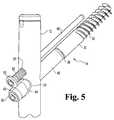
- FIG. 5is an enlarged perspective view of the assembled apparatus shown in FIGS. 3-4 .
- FIG. 6is an enlarged view of a portion labeled 6 of the apparatus shown in FIG. 3 .
- FIG. 7is an enlarged view of the portion labeled 7 of the apparatus shown in FIG. 3 .
- FIG. 8is an enlarged view of an alternative configuration of the portion labeled 7 in FIG. 3 .
- FIG. 9is an exploded perspective view of an alternative embodiment of the fracture fixation apparatus disclosed herein.
- FIG. 10is an enlarged cross-sectional view of the embodiment shown in FIG. 9 .
- FIG. 11is an exploded perspective view of a further embodiment of the fracture fixation apparatus disclosed herein.
- a fracture fixation apparatus 10is shown in FIG. 1 implanted within a femur having a fracture F at the neck N of the bone.
- the apparatus 10includes a stabilizing member in the form of an intramedullary rod or nail 12 extending through the medullary canal of the femoral shaft S, a lag screw assembly spanning the fracture F and engaging the femoral head, and a control member 16 .
- the intramedullary rod 12defines a central bore 20 that extends along substantially the entire length of the body 22 .
- the body 22may be configured in a known manner to be implanted within the medullary canal of a long bone, such as the femur. For instance, the body may define a distal aperture to receive a transverse screw for fixing the distal end of the rod to the femur.
- the rod 12further defines a pair of apertures near its proximal end, namely a first transverse aperture 24 and a second transverse aperture 26 .
- the second transverse apertureincludes internal threads for engaging the control member 16 as described herein.
- the rodfurther includes an upper threaded portion 28 within the central bore 20 for engaging a locking post, as also described herein.
- the lag screw assembly 14includes a lag screw 30 having a distal portion 32 configured to engage the head H of the fractured femur, as shown in FIG. 1 .
- the distal portion 32defines bone threads 33 that can be configured in a manner typical for a lag screw.
- the lag screw 30may define a bore 34 along its entire length.
- the boremay define an internal driving feature, such as a hex or Torx configuration, for engagement by a driving tool to implant the lag screw in a known manner.
- the lag screwfurther includes a proximal portion 35 that interfaces with the distal portion 32 at a shoulder 36 .
- the proximal portion 35has a smaller diameter than the distal portion 32 , so the shoulder 36 represents a step between the two portions.
- the lag screwincludes a radially expandable segment 37 in one embodiment, with internal threads 38 defined within the bore 34 immediately distally adjacent the expandable segment. The segment 37 and threads 38 form part of a mechanism for locking the components of the lag screw assembly together, as described in more detail herein.
- the lag screw assembly 14further includes an elongated sleeve 40 that is cylindrical and defines a bore 42 therethrough.
- the bore 42is sized so that the sleeve 40 fits over the proximal portion 35 of the lag screw 30 but the distal end 43 of the sleeve butts up against the shoulder 36 .
- the inner diameter of the sleeve bore 42is greater than the diameter of the lag screw proximal portion but smaller than the diameter of the lag screw distal portion.
- the sleeve boreis sized to allow the lag screw to freely rotate within the sleeve while the lag screw is threaded into the fractured head H of the femur in the illustrated embodiment.
- the length of the sleeveis preferably at least equal to the length of the proximal portion 35 of the lag screw measured from the shoulder 36 .
- the sleeve 40defines a longitudinal outer groove 44 having an open end 45 at the proximal end 47 of the sleeve and a terminus 46 part way along the length of the sleeve. This groove interfaces with the control member 16 as described herein.
- the sleeve 40When the lag screw assembly is constructed, the sleeve 40 is disposed over the proximal portion 35 of the lag screw 30 .
- the lag screwis inserted through the first transverse aperture 20 in the intramedullary rod 12 , as shown in FIGS. 2 , 3 and 5 .
- the aperture 20is sized to accept the lag screw and sleeve in a close running fit to allow the lag screw assembly to slide longitudinally through the aperture.
- the lag screwAs the lag screw is threaded into the femoral head H, it rotates freely within the sleeve 40 .
- the sleeve 40When the lag screw 30 has been fully threaded into the fractured bone segment, the sleeve 40 is rotated so that the outer groove 44 is directly aligned with the second transverse aperture 24 .
- the second apertureis immediately above or proximal to the first aperture for the lag screw.
- the sleeveis rotated until the groove 44 faces upward toward the second aperture.
- the lag screw assembly 14further includes a locking screw 50 having a threaded end 51 and a conical head 53 .
- the threaded end 51is configured to engage the internal threads 38 at the end of the proximal portion 35 of the lag screw.
- the locking screw 50thus extends through the radially expandable segment 37 of the lag screw and into engagement with the threads 38 .
- the conical head 53contacts the radially expandable segment, as shown in the enlarged view of FIG. 6 .
- the conical headincreases in diameter from a diameter smaller than the un-expanded diameter of the segment 37 to a diameter that is larger than that of the segment.
- the locking screw 50thus further acts to compress and clamp the sleeve between the locking screw and the lag screw shoulder.
- the locking sleeve and lag screware thus firmly locked together so that the two components move or are prevented from moving as one.
- the head 53preferably incorporates a driving feature, such as an internal hex or Torx configuration for engagement by a driving tool to implant the thread the locking screw into the radially expandable segment.
- the fracture fixation apparatus 10further contemplates means for preventing excessive collapse of the fracture F and excessive lateral movement of the lag screw relative to the femoral shaft S.
- the apparatusincludes a control member 16 that engages both the intramedullary rod 12 and the lag screw 14 in a manner that prevents rotation of the lag screw (and consequently the fractured bone segment) while also restricting lateral movement.
- the control member 16includes a non-threaded distal portion 60 that is configured to penetrate the fractured bone segment, as shown in FIG. 1 .
- the distal portion 60may be in the form of an orthopaedic nail.
- the memberfurther includes an intermediate portion 62 that includes outer threads 63 .
- the threads 63are configured to mate with the internal threads 27 of the second transverse aperture 24 in the intramedullary rod 12 when the control member extends through that aperture.
- the memberterminates in a proximal head 65 that is sized to prevent passage of the head through the second transverse aperture.
- the head 65is, however, sized to slidingly engage the groove 44 in the locking sleeve 40 of the lag screw assembly, as best seen in the enlarged view of FIG. 5 .
- the groove 44is defined at a radius that is substantially equal to the radius of the head 65 .
- the depth of the grooveis sufficient to capture the head and prevent its dislodgement when the fixation apparatus is under load.
- the headhas a diameter of about 15 mm and a radius of about 7.5 mm.
- the groove 44is thus formed at a radius of about 7.5 mm at a depth of about 0.4 mm, subtending an angle of about 40-50°.
- a driving featureis preferably incorporated into the head 65 , such as an internal hex or Torx configuration for engagement by an appropriate driving tool.
- the head 65rotates and slides along the groove 44 . It can be appreciated that as the control member 16 is advanced through the second transverse aperture 26 the distal portion 60 is extending essentially parallel to the lag screw 30 into the fractured bone segment.
- This placement of the control member relative to the lag screw within the fractured femoral head Hprevents the head H from rotating about the longitudinal axis of the lag screw relative to the remainder of the femur. Any torque that may be exerted on the femoral head H that might otherwise cause the fractured segment to rotate is absorbed by the offset lag screw and control member.
- the fixation apparatus 10provides greater resistance to fracture segment rotation than prior devices due to the greater offset achieved between the lag screw and control member.
- the two transverse apertures 24 , 26are offset by the radius of the proximal head 65 of the control member (less the depth of the groove 44 within which a portion of the head resides). The greater the offset, the greater the torque resistance capability of the construct.
- the proximal head 65operates to prevent excessive lateral movement of the lag screw assembly 14 .
- the lag screwmoves laterally, essentially moving retrograde through the first transverse aperture 24 .
- the control member 16and more importantly the proximal head 65 , remains stationary due to the threaded engagement between the control member and the intramedullary rod.
- the locking sleeve 40 and its groove 44thus slide along the proximal head until the terminus 46 reaches the head. Since the groove 44 ends, the sleeve can no longer travel past the proximal head 65 . The lateral movement of the sleeve 40 and consequently the lag screw 30 locked to the sleeve is stopped.
- the groovehas a length of about 40 mm from the open end 45 to the terminus 46 .
- the maximum lateral travel permitted by the control member 16 in this embodimentcannot exceed 40 mm.
- the actual maximum traveldepends upon the position of the proximal head 65 relative to the terminus 46 of the groove 44 when the apparatus 10 is implanted, which will typically be less than the length of the groove.
- This relative travel, and consequently the maximum lateral movement of the lag screwcan be adjusted when the apparatus is implanted by varying the relative position of the head to the groove terminus. The closer the head 65 is to the terminus 46 at the initial implantation, the less lateral travel that is permitted by the control member 16 .
- a locking mechanismmay be provided for locking the control member 16 to the intramedullary rod 12 .
- a locking post 70is disposed within the central bore 20 of the intramedullary rod 12 .
- the locking postincludes a threaded end 71 that engages the internal threads 38 of the central bore.
- An engagement tip 72projects from the threaded end and is configured to engage the threaded portion 63 of the control member 16 .
- a capture screw 75may be provided to lock the locking post 70 in position and to prevent its backing out.
- the capture screw 75thus includes a threaded end 76 that engages the internal threads 38 of the central bore and bears against the proximal face of the locking post.
- An enlarged head 75may be provided to seal against the top of the intramedullary rod 12 .
- a driving featureis preferably provided in the proximal faces of the locking post 70 and capture screw 75 for engagement by a driving tool.
- the locking postbears against the control member 16 within the second transverse aperture 26 .
- the engagement tip 72may be conical, as shown in FIG. 7 , or may have other configurations that provide a firm grip against the control member. In certain embodiments, the tip 72 may be malleable to conform to the threaded portion 63 of the control member.
- the locking post 70When fully engaged, the locking post 70 operates to maintain the control member fixed within the transverse aperture 26 . The locking post thus prevents back out of the control member 16 which would otherwise thwart a central purpose of the member to restrict lateral movement of the lag screw.
- the fracture fixation apparatus 10is preferably used with both the lag screw 14 and the control member 16 .
- the control member 16is not necessary to prevent or restrict back out or lateral movement, or even rotation, of the lag screw. In those applications the control member 16 is not used.
- the locking post 70may then be threaded more deeply into the internal threads 38 of the central bore until the tip 72 engages the sleeve 40 , as shown in FIG. 8 , which is itself locked to the lag screw in the manner explained above.
- the capture screwmay be modified so that the threaded end 76 can be threaded deeper into the central bore 20 to contact the proximal face of the locking post.
- a locking post 80may be provided as shown in FIGS. 9-10 .
- the locking postincludes an unthreaded upper tube 81 sized to freely slide within the central bore.
- the distal end of the tubeis formed into opposite prongs 82 that are spaced apart to pass around the threaded portion 63 of the control member 16 disposed within the second transverse aperture 26 , as best seen in FIG. 10 .
- the prongsare sized so that the tips 83 of the prongs can bear against the sleeve 40 (or sleeve 40 ′ shown in FIG. 10 ).
- the tips 83are preferably angled to conform to the surface of the locking sleeve. This surface to surface engagement increases the frictional locking capability of the locking post 80 to prevent or significantly restrict the lateral migration of the lag screw assembly.
- This alternative embodiment locking post 80may be particularly useful with the lag screw assembly 14 ′ embodiment shown in FIGS. 9-10 .
- This lag screw assembly 14 ′includes a modified lag screw 30 ′ that does not incorporate the radially expandable segment 37 of the embodiment shown in FIGS. 2 , 6 .
- the modified lag screw 30 ′includes a shoulder that is modified to provide a circumferential depression 36 ′ at the interface between the distal portion 32 ′ and proximal portion 35 ′.
- the locking sleeve 40 ′is also modified so that its distal end 43 ′ curves inward to engage the circumferential depression 36 ′, as best seen in FIG. 10 .
- the modified lag screw assembly 14 ′also includes a modified locking screw 50 ′.
- the locking screwincludes a threaded post 51 configured to engage internal threads 38 ′ of the lag screw 30 ′.
- the head 53 ′is configured to bear against the proximal end 47 ′ of the modified locking sleeve 40 ′.
- the proximal end 37 ′ of the lag screw 30 ′is offset from the proximal end 47 ′ of the locking sleeve 40 ′ so that threading the locking screw 50 ′ into the threads 38 ′ allows the locking screw to exert a compressive force against the sleeve.
- This compressionwill clamp the sleeve 40 ′ between the depression 36 ′ and the shoulder formed by the distal portion 32 ′ of the lag screw and the head 53 ′ of the locking screw 50 ′
- the locking screwthus locks the sleeve 40 ′ to the lag screw 30 ′.
- the modified locking post 80provides further locking force to the sleeve.
- the engagement between the locking sleeve and the lag screwmay be modified as shown in FIG. 11 .
- the lag screw assembly 14 ′′includes a locking sleeve 40 ′′ with a slot 44 ′′ that is configured like the other embodiments 40 and 40 ′.
- the proximal end 47 ′′ of the sleeve 40 ′′is castellated to include a series of circumferentially arranged recesses 48 ′′.
- the locking screw 50 ′′is also modified from the prior embodiments to mate with a nut 85 .
- the nut 85includes at least two prongs 86 that are configured to fit within diametrically opposite recesses 48 ′′ in the locking sleeve 40 ′′.
- the nut 85defines an opening 87 through which the locking screw 50 ′′ passes.
- the head 53 ′′ of the screwis contoured to fit within a contoured seat 88 of the nut.
- the screwfurther includes a threaded stem 51 ′′ that is configured to engage the internal threads of the lag screw, such as threads 38 shown in FIG. 6 , in the manner described above.
- the lag screw 30 ′′ of the assembly 14 ′′is also modified from the prior embodiments.
- the end of the proximal portion 35 ′′is modified to incorporate at least two diametrically opposite notches 37 ′′.
- the notches 37 ′′are adapted to receive the prongs 86 of the nut 85 .
- the lag screw assembly 14 ′′is assembled by sliding the sleeve 40 ′′ over the proximal portion 35 ′′ of the lag screw 30 ′′.
- the sleeveis oriented so that the groove 44 ′′ is aligned with the second transverse aperture 26 of the intramedullary rod 12 for engagement by the control member 16 in the manner described.
- the lag screw and locking sleevemay be rotated slightly so that the notches 37 ′′ align with recesses 48 ′′ in the castellated proximal end 47 ′′ of the sleeve.
- the nutmay then be positioned over of the two components with the prongs 86 positioned with aligned pairs of notches 37 ′′ and recesses 48 ′′.
- the locking screw 50 ′′is then advanced into the threaded end of the lag screw and the head 53 ′′ is tightened down into the contoured seat 88 of the nut.
- Tightening the locking screw 50 ′′not only compresses and clamps the locking sleeve 40 ′′ against the distal portion 32 ′′ of the lag screw, it also rotationally locks the sleeve and lag screw together by way of the prongs 86 .
- the entire lag screw assembly 14 ′′is locked against rotation relative to the intramedullary rod. The completed assembly thus prevents rotation of the fractured bone segment as well as limits collapse of the fracture and lateral migration of the lag screw.
- control member 16 ′need not engage the fractured bone segment in the manner shown in FIG. 1 .
- an abbreviated control member 16 ′may be provided as depicted in FIG. 9 .
- This modified control memberonly includes the proximal head 65 ′ and the threaded portion 63 ′ adapted to engage the internal threads of the second transverse aperture 26 in the intramedullary rod.
- This abbreviated control memberdoes not include the elongated distal portion of the prior embodiment (i.e., the distal portion 60 of the control member 16 shown in FIG. 2 ), so the control member 16 ′ does not operate to prevent rotation of the fractured bone segment about the axis of the lag screw.
- this embodiment of the control member 16 ′is acceptable for fracture fixation where there is little risk of fracture rotation.
- the groove 44 / 44 ′/ 44 ′′ in the corresponding locking sleeve 40 / 40 ′/ 40 ′′has a length sized to permit a limited amount of lateral migration of the lag screw during fracture collapse.
- the length of the groovecan be made much shorter to reduce or even eliminate the lateral movement of the lag screw.
- each of the componentsis sized for implantation within the proximal portion of the femur.
- the intramedullary rod 12 , lag screw 40 / 40 ′/ 40 ′′ and control member 16 / 16 ′can be provided in diameters and lengths suitable for the patient's anatomy.
- the fracture fixation apparatus 10may be adapted for fixation of fractures other than of the femur.
- the intramedullary rod 12may be replaced by a bone plate, for instance, that incorporates the first and second transverse apertures 24 , 26 .
- Appropriate changes to the geometry and dimensions of the lag screw assembly and control membermay also be made for these other fracture fixation applications, while retaining the anti-rotation and anti-lateral migration features provided by the apparatus of the embodiments disclosed herein.
Landscapes
- Health & Medical Sciences (AREA)
- Orthopedic Medicine & Surgery (AREA)
- Surgery (AREA)
- Life Sciences & Earth Sciences (AREA)
- Heart & Thoracic Surgery (AREA)
- Nuclear Medicine, Radiotherapy & Molecular Imaging (AREA)
- Engineering & Computer Science (AREA)
- Biomedical Technology (AREA)
- Neurology (AREA)
- Medical Informatics (AREA)
- Molecular Biology (AREA)
- Animal Behavior & Ethology (AREA)
- General Health & Medical Sciences (AREA)
- Public Health (AREA)
- Veterinary Medicine (AREA)
- Surgical Instruments (AREA)
Abstract
Description
Claims (15)
Priority Applications (2)
| Application Number | Priority Date | Filing Date | Title |
|---|---|---|---|
| US12/164,475US8100911B2 (en) | 2008-06-30 | 2008-06-30 | Fracture fixation apparatus |
| PCT/US2009/047622WO2010002588A1 (en) | 2008-06-30 | 2009-06-17 | Fracture fixation apparatus |
Applications Claiming Priority (1)
| Application Number | Priority Date | Filing Date | Title |
|---|---|---|---|
| US12/164,475US8100911B2 (en) | 2008-06-30 | 2008-06-30 | Fracture fixation apparatus |
Publications (2)
| Publication Number | Publication Date |
|---|---|
| US20090326534A1 US20090326534A1 (en) | 2009-12-31 |
| US8100911B2true US8100911B2 (en) | 2012-01-24 |
Family
ID=40941766
Family Applications (1)
| Application Number | Title | Priority Date | Filing Date |
|---|---|---|---|
| US12/164,475Expired - Fee RelatedUS8100911B2 (en) | 2008-06-30 | 2008-06-30 | Fracture fixation apparatus |
Country Status (2)
| Country | Link |
|---|---|
| US (1) | US8100911B2 (en) |
| WO (1) | WO2010002588A1 (en) |
Cited By (18)
| Publication number | Priority date | Publication date | Assignee | Title |
|---|---|---|---|---|
| US20090048600A1 (en)* | 2007-06-22 | 2009-02-19 | Anthem Orthopaedics Van, Llc | Intramedullary rod with pivotable fastener and method for using same |
| US20100094293A1 (en)* | 2008-10-11 | 2010-04-15 | Anthem Orthopaedics Van, Llc | Intramedullary rod with pivotable and fixed fasteners and method for using same |
| US20120143192A1 (en)* | 2009-06-30 | 2012-06-07 | Kohsuke Watanabe | Polyaxial fastener systems and methods |
| USD680221S1 (en)* | 2012-03-09 | 2013-04-16 | Yechiel Gotfried | Surgical nail |
| USD714938S1 (en) | 2013-08-01 | 2014-10-07 | Yechiel Gotfried | Surgical nail |
| US8939978B2 (en) | 2007-03-20 | 2015-01-27 | Smith & Nephew, Inc. | Orthopaedic plate and screw assembly |
| US9782206B2 (en) | 2011-02-08 | 2017-10-10 | Stryker European Holdings I, Llc | Implant system for bone fixation |
| US9861418B2 (en) | 2012-02-08 | 2018-01-09 | Epix Orthopaedics, Inc. | Implant insertion device with continuously adjustable targeting assembly |
| US9895177B2 (en) | 2016-01-15 | 2018-02-20 | ARTHREX, GmbH | Bone fixation device for treatment of femoral fractures |
| US10092334B2 (en)* | 2016-09-01 | 2018-10-09 | Omic Corporation | Femur fixation apparatus |
| US10123828B2 (en) | 2013-03-15 | 2018-11-13 | Epix Orthopaedics, Inc. | Implantable device with pivotable fastener and self-adjusting set screw |
| US10492803B2 (en) | 2016-09-22 | 2019-12-03 | Globus Medical, Inc. | Systems and methods for intramedullary nail implantation |
| US10543026B2 (en) | 2014-04-21 | 2020-01-28 | The General Hospital Corporation | Fracture fixation device having clip for stabilizing intramedullary nail |
| US10758280B2 (en) | 2017-10-09 | 2020-09-01 | Acumed Llc | System and method for bone fixation using a nail locked to an encircling anchor |
| US11083503B2 (en) | 2016-09-22 | 2021-08-10 | Globus Medical, Inc. | Systems and methods for intramedullary nail implantation |
| US11633219B2 (en) | 2019-06-26 | 2023-04-25 | Globus Medical, Inc. | Fenestrated pedicle nail |
| US11857228B2 (en) | 2020-03-06 | 2024-01-02 | Stryker European Operations Limited | Set screw for femoral nail |
| US12207849B2 (en) | 2020-03-06 | 2025-01-28 | Stryker European Operations Limited | Set screw for femoral nail |
Families Citing this family (42)
| Publication number | Priority date | Publication date | Assignee | Title |
|---|---|---|---|---|
| EP2094197B8 (en) | 2006-12-07 | 2016-03-09 | IHip Surgical, LLC | Apparatus for total hip replacement |
| US8974540B2 (en) | 2006-12-07 | 2015-03-10 | Ihip Surgical, Llc | Method and apparatus for attachment in a modular hip replacement or fracture fixation device |
| US8579985B2 (en) | 2006-12-07 | 2013-11-12 | Ihip Surgical, Llc | Method and apparatus for hip replacement |
| US20080262498A1 (en)* | 2007-04-18 | 2008-10-23 | Fernandez Dell Oca Alberto Angel | Double locked hip implant |
| US9017329B2 (en) | 2008-06-24 | 2015-04-28 | Extremity Medical, Llc | Intramedullary fixation assembly and method of use |
| US9044282B2 (en) | 2008-06-24 | 2015-06-02 | Extremity Medical Llc | Intraosseous intramedullary fixation assembly and method of use |
| US9289220B2 (en) | 2008-06-24 | 2016-03-22 | Extremity Medical Llc | Intramedullary fixation assembly and method of use |
| US8313487B2 (en)* | 2008-06-24 | 2012-11-20 | Extremity Medical Llc | Fixation system, an intramedullary fixation assembly and method of use |
| US8303589B2 (en) | 2008-06-24 | 2012-11-06 | Extremity Medical Llc | Fixation system, an intramedullary fixation assembly and method of use |
| US8328806B2 (en) | 2008-06-24 | 2012-12-11 | Extremity Medical, Llc | Fixation system, an intramedullary fixation assembly and method of use |
| CA2749684C (en) | 2009-01-16 | 2016-04-26 | Carbofix Orthopedics Ltd. | Composite material bone implant |
| EP2737865B1 (en)* | 2010-01-08 | 2016-04-20 | Biedermann Technologies GmbH & Co. KG | Bone screw |
| US20130041414A1 (en)* | 2010-03-10 | 2013-02-14 | Advanced Orthopaedic Solutions, Inc. | Telescoping Bone Screw |
| CN102232863A (en)* | 2010-04-23 | 2011-11-09 | 常州奥斯迈医疗器械有限公司 | Intramedullary nail device |
| CN105877829B (en)* | 2010-06-07 | 2018-06-22 | 卡波菲克斯整形有限公司 | Composite material bone implant |
| US10154867B2 (en) | 2010-06-07 | 2018-12-18 | Carbofix In Orthopedics Llc | Multi-layer composite material bone screw |
| CN101912299B (en)* | 2010-09-03 | 2012-03-21 | 唐佩福 | Integrated intramedullary nail system for treating proximal femoral fracture |
| JP5931924B2 (en)* | 2011-01-21 | 2016-06-08 | シンセス・ゲーエムベーハーSynthes GmbH | Augmentable trochanteric femoral nail |
| US20140031934A1 (en)* | 2012-07-26 | 2014-01-30 | Warsaw Orthopedic, Inc. | Sacro-iliac joint implant system and method |
| DE202012103384U1 (en)* | 2012-09-05 | 2012-09-24 | Signus Medizintechnik Gmbh | Pelvic ring implant |
| ES2628324T3 (en)* | 2013-01-31 | 2017-08-02 | Stryker European Holdings I, Llc | Modular background |
| JP5914771B2 (en)* | 2013-10-11 | 2016-05-11 | プロスパー株式会社 | Osteosynthesis and osteosynthesis |
| US9480509B2 (en) | 2013-11-07 | 2016-11-01 | Four Studies Ltd. | Osteosynthesis apparatus for proximal femur fracture and master screw-type screw apparatus for osteosynthesis apparatus for proximal femur fracture |
| US10080596B2 (en) | 2013-12-09 | 2018-09-25 | Acumed Llc | Hip fixation with load-controlled dynamization |
| US9526542B2 (en)* | 2014-05-07 | 2016-12-27 | Acumed Llc | Hip fixation with load-controlled dynamization |
| US9463055B2 (en) | 2013-12-09 | 2016-10-11 | Acumed Llc | Plate-based compliant hip fixation system |
| US9433451B2 (en) | 2013-12-09 | 2016-09-06 | Acumed Llc | Hip fixation system with a compliant fixation element |
| ES2805053T3 (en) | 2013-12-09 | 2021-02-10 | Acumed Llc | Nail-based elastic hip fixation system |
| US9517094B1 (en)* | 2014-05-09 | 2016-12-13 | Savage Medical Design LLC | Intramedullary fixation apparatus for use in hip and femur fracture surgery |
| CN104055567A (en)* | 2014-07-10 | 2014-09-24 | 苏州吉美瑞医疗器械有限公司 | Locking nail of PFNA |
| US10617458B2 (en) | 2015-12-23 | 2020-04-14 | Carbofix In Orthopedics Llc | Multi-layer composite material bone screw |
| JP6491625B2 (en)* | 2016-08-31 | 2019-03-27 | 株式会社ビー・アイ・テック | Gamma type nail device |
| PL232289B1 (en)* | 2017-03-22 | 2019-05-31 | Medgal Spolka Z Ograniczona Odpowiedzialnoscia | Reconstructive thigh nail for treatment of fractures within the neck of femur and the greater trochanter |
| US10932828B2 (en) | 2018-01-25 | 2021-03-02 | Advanced Orthopaedic Solutions, Inc. | Bone nail |
| CN111904579B (en)* | 2020-09-01 | 2022-12-06 | 东南大学 | Intramedullary nail for treating femoral fracture |
| US11553950B2 (en)* | 2020-10-27 | 2023-01-17 | Spinal Generations, Llc | Lag screw systems and nail systems and methods incorporating the same |
| CN113648041B (en)* | 2021-02-02 | 2023-03-10 | 浙江德康医疗器械有限公司 | An internal fixation repair system for intertrochanteric fracture |
| WO2023086256A1 (en)* | 2021-11-12 | 2023-05-19 | Smith & Nephew, Inc. | Orthopedic fixation device with lag screw and compression screw |
| CN114259287B (en)* | 2021-12-24 | 2025-08-08 | 北京理贝尔生物工程研究所有限公司 | Intramedullary locking nail assembly |
| CN119730802A (en)* | 2022-11-07 | 2025-03-28 | I.T.S.有限责任公司 | Device for treating bone fractures |
| AT527159A1 (en)* | 2023-04-21 | 2024-11-15 | I T S Gmbh | Flexible device for treating a bone fracture |
| CN119896526B (en)* | 2024-12-19 | 2025-07-25 | 中国人民解放军总医院第四医学中心 | Sleeve combined type tension pressurizing internal fixing screw |
Citations (16)
| Publication number | Priority date | Publication date | Assignee | Title |
|---|---|---|---|---|
| US5032125A (en) | 1990-02-06 | 1991-07-16 | Smith & Nephew Richards Inc. | Intramedullary hip screw |
| US5041116A (en) | 1990-05-21 | 1991-08-20 | Wilson James T | Compression hip screw system |
| US5176681A (en) | 1987-12-14 | 1993-01-05 | Howmedica International Inc. | Intramedullary intertrochanteric fracture fixation appliance and fitting device |
| US5454813A (en) | 1991-06-24 | 1995-10-03 | Howmedica International Inc. | Intramedullary intertrochanteric fracture fixation appliance |
| US5562666A (en) | 1986-12-30 | 1996-10-08 | Smith & Nephew Richards Inc. | Method for treating intertrochanteric fracture utilizing a femoral fracture device |
| US5713902A (en) | 1993-06-01 | 1998-02-03 | Endocare Ag | Osteosynthesis auxiliary for the treatment of subtrochanteric peritrochanteric and femoral-neck fractures |
| US6228086B1 (en) | 1997-03-19 | 2001-05-08 | Stryker Trauma-Selzach Ag | Modular intramedullary nail |
| US6235031B1 (en)* | 2000-02-04 | 2001-05-22 | Encore Medical Corporation | Intramedullary fracture fixation device |
| EP1175872A2 (en) | 2000-07-27 | 2002-01-30 | KOI Inc. | Intramedullary nail and lag screw |
| US6423066B1 (en)* | 1998-12-28 | 2002-07-23 | Stryker Trauma Gmbh | Neck screw |
| US6443954B1 (en)* | 2001-04-24 | 2002-09-03 | Dale G. Bramlet | Femoral nail intramedullary system |
| US20030004514A1 (en) | 1999-12-03 | 2003-01-02 | Robert Frigg | Intramedullary nail |
| WO2003028567A1 (en) | 2001-10-01 | 2003-04-10 | Synthes (U.S.A.) | Device for rotational stabilization of bone segments |
| EP0968685B1 (en) | 1998-06-30 | 2004-09-01 | Aesculap AG & Co. KG | Device for treating bone fractures |
| US20050055024A1 (en) | 2003-09-08 | 2005-03-10 | James Anthony H. | Orthopaedic implant and screw assembly |
| US20080119856A1 (en) | 2006-11-20 | 2008-05-22 | Yechiel Gotfried | Intramedullary nail system and method for fixation of a fractured bone |
- 2008
- 2008-06-30USUS12/164,475patent/US8100911B2/ennot_activeExpired - Fee Related
- 2009
- 2009-06-17WOPCT/US2009/047622patent/WO2010002588A1/enactiveApplication Filing
Patent Citations (19)
| Publication number | Priority date | Publication date | Assignee | Title |
|---|---|---|---|---|
| US5562666A (en) | 1986-12-30 | 1996-10-08 | Smith & Nephew Richards Inc. | Method for treating intertrochanteric fracture utilizing a femoral fracture device |
| US5176681A (en) | 1987-12-14 | 1993-01-05 | Howmedica International Inc. | Intramedullary intertrochanteric fracture fixation appliance and fitting device |
| US5032125A (en) | 1990-02-06 | 1991-07-16 | Smith & Nephew Richards Inc. | Intramedullary hip screw |
| US5041116A (en) | 1990-05-21 | 1991-08-20 | Wilson James T | Compression hip screw system |
| US5454813A (en) | 1991-06-24 | 1995-10-03 | Howmedica International Inc. | Intramedullary intertrochanteric fracture fixation appliance |
| US5713902A (en) | 1993-06-01 | 1998-02-03 | Endocare Ag | Osteosynthesis auxiliary for the treatment of subtrochanteric peritrochanteric and femoral-neck fractures |
| US6228086B1 (en) | 1997-03-19 | 2001-05-08 | Stryker Trauma-Selzach Ag | Modular intramedullary nail |
| EP0968685B1 (en) | 1998-06-30 | 2004-09-01 | Aesculap AG & Co. KG | Device for treating bone fractures |
| US6423066B1 (en)* | 1998-12-28 | 2002-07-23 | Stryker Trauma Gmbh | Neck screw |
| US20030004514A1 (en) | 1999-12-03 | 2003-01-02 | Robert Frigg | Intramedullary nail |
| US6235031B1 (en)* | 2000-02-04 | 2001-05-22 | Encore Medical Corporation | Intramedullary fracture fixation device |
| US20020032445A1 (en)* | 2000-07-27 | 2002-03-14 | Hiroo Fujiwara | Intramedullary nail |
| EP1175872A2 (en) | 2000-07-27 | 2002-01-30 | KOI Inc. | Intramedullary nail and lag screw |
| US6443954B1 (en)* | 2001-04-24 | 2002-09-03 | Dale G. Bramlet | Femoral nail intramedullary system |
| WO2003028567A1 (en) | 2001-10-01 | 2003-04-10 | Synthes (U.S.A.) | Device for rotational stabilization of bone segments |
| US20050055024A1 (en) | 2003-09-08 | 2005-03-10 | James Anthony H. | Orthopaedic implant and screw assembly |
| US20050149025A1 (en) | 2003-09-08 | 2005-07-07 | Joseph Ferrante | Orthopaedic plate and screw assembly |
| US7527627B2 (en)* | 2003-09-08 | 2009-05-05 | Smith & Nephew, Inc. | Orthopaedic implant and screw assembly |
| US20080119856A1 (en) | 2006-11-20 | 2008-05-22 | Yechiel Gotfried | Intramedullary nail system and method for fixation of a fractured bone |
Non-Patent Citations (2)
| Title |
|---|
| PCT Search Report for PCT/US2009/047622, mailed on Sep. 1, 2009. |
| Stryker, "Gamma3 tm-The Compact Titanium Version of the Gamma tm Nail System", 2005, US. |
Cited By (27)
| Publication number | Priority date | Publication date | Assignee | Title |
|---|---|---|---|---|
| US8939978B2 (en) | 2007-03-20 | 2015-01-27 | Smith & Nephew, Inc. | Orthopaedic plate and screw assembly |
| US9861403B2 (en) | 2007-06-22 | 2018-01-09 | Epix Orthopaedics, Inc. | Method for pivoting a fastener |
| US10687871B2 (en) | 2007-06-22 | 2020-06-23 | Epix Orthopaedics, Inc. | Intramedullary rod for pivoting a fastener |
| US20090048600A1 (en)* | 2007-06-22 | 2009-02-19 | Anthem Orthopaedics Van, Llc | Intramedullary rod with pivotable fastener and method for using same |
| US8906023B2 (en) | 2007-06-22 | 2014-12-09 | Epix Orthopaedics, Inc. | Intramedullary rod for pivoting a fastener |
| US20100094293A1 (en)* | 2008-10-11 | 2010-04-15 | Anthem Orthopaedics Van, Llc | Intramedullary rod with pivotable and fixed fasteners and method for using same |
| US8790343B2 (en)* | 2008-10-11 | 2014-07-29 | Epix Orthopaedics, Inc. | Intramedullary rod with pivotable and fixed fasteners and method for using same |
| US20120143192A1 (en)* | 2009-06-30 | 2012-06-07 | Kohsuke Watanabe | Polyaxial fastener systems and methods |
| US8834469B2 (en)* | 2009-06-30 | 2014-09-16 | Smith & Nephew, Inc. | Orthopaedic implant and fastener assembly |
| US9782206B2 (en) | 2011-02-08 | 2017-10-10 | Stryker European Holdings I, Llc | Implant system for bone fixation |
| US10034696B2 (en) | 2011-02-08 | 2018-07-31 | Stryker European Holdings I, Llc | Implant system for bone fixation |
| US9861418B2 (en) | 2012-02-08 | 2018-01-09 | Epix Orthopaedics, Inc. | Implant insertion device with continuously adjustable targeting assembly |
| USD680221S1 (en)* | 2012-03-09 | 2013-04-16 | Yechiel Gotfried | Surgical nail |
| US10123828B2 (en) | 2013-03-15 | 2018-11-13 | Epix Orthopaedics, Inc. | Implantable device with pivotable fastener and self-adjusting set screw |
| USD714938S1 (en) | 2013-08-01 | 2014-10-07 | Yechiel Gotfried | Surgical nail |
| US10543026B2 (en) | 2014-04-21 | 2020-01-28 | The General Hospital Corporation | Fracture fixation device having clip for stabilizing intramedullary nail |
| US9895177B2 (en) | 2016-01-15 | 2018-02-20 | ARTHREX, GmbH | Bone fixation device for treatment of femoral fractures |
| US10092334B2 (en)* | 2016-09-01 | 2018-10-09 | Omic Corporation | Femur fixation apparatus |
| US10492803B2 (en) | 2016-09-22 | 2019-12-03 | Globus Medical, Inc. | Systems and methods for intramedullary nail implantation |
| US11083503B2 (en) | 2016-09-22 | 2021-08-10 | Globus Medical, Inc. | Systems and methods for intramedullary nail implantation |
| US11490905B2 (en) | 2016-09-22 | 2022-11-08 | Globus Medical, Inc. | Systems and methods for intramedullary nail implantation |
| US12285178B2 (en) | 2016-09-22 | 2025-04-29 | Globus Medical, Inc. | Systems and methods for intramedullary nail implantation |
| US10758280B2 (en) | 2017-10-09 | 2020-09-01 | Acumed Llc | System and method for bone fixation using a nail locked to an encircling anchor |
| US11633219B2 (en) | 2019-06-26 | 2023-04-25 | Globus Medical, Inc. | Fenestrated pedicle nail |
| US11857228B2 (en) | 2020-03-06 | 2024-01-02 | Stryker European Operations Limited | Set screw for femoral nail |
| US12207849B2 (en) | 2020-03-06 | 2025-01-28 | Stryker European Operations Limited | Set screw for femoral nail |
| US12349948B2 (en) | 2020-03-06 | 2025-07-08 | Stryker European Operations Limited | Set screw for femoral nail |
Also Published As
| Publication number | Publication date |
|---|---|
| WO2010002588A1 (en) | 2010-01-07 |
| US20090326534A1 (en) | 2009-12-31 |
Similar Documents
| Publication | Publication Date | Title |
|---|---|---|
| US8100911B2 (en) | Fracture fixation apparatus | |
| CN101631505B (en) | Hip fracture device with barrel and end caps for load control | |
| US9788862B2 (en) | Sacral fixation system | |
| US9247963B2 (en) | Bone compression device and methods | |
| US10064670B2 (en) | Sacral fixation system | |
| RU2634663C2 (en) | Pelvic ring implant | |
| US8177786B2 (en) | Orthopaedic trauma hip screw assembly and associated method | |
| US5034012A (en) | Intramedullary nail with loop tip | |
| CA2701062C (en) | Bone anchoring device for the operative repair of fractures | |
| EP2185091B9 (en) | Multi-axial bone anchor assembly | |
| EP0486483A1 (en) | Intramedullary intertrochanteric fracture fixation appliance and fitting device | |
| US10575883B2 (en) | Active fracture compression implants | |
| US20030149436A1 (en) | Fixation and compression fastener assembly for bone fractures | |
| CN106102613B (en) | Bone screw assembly | |
| US11701147B2 (en) | Bone anchor for triangular iliosacral osteosynthesis | |
| US9101420B2 (en) | Device for fixation of bone fragments at bone fractures | |
| US10736675B2 (en) | Endosseous screw assembly and internal fixation system comprising said endosseous screw assembly | |
| EP3150154A1 (en) | Endosseous screw assembly and internal fixation system comprising said endosseous screw assembly | |
| AU2013373795B2 (en) | MTV implantation set |
Legal Events
| Date | Code | Title | Description |
|---|---|---|---|
| AS | Assignment | Owner name:DEPUY PRODUCTS, INC., INDIANA Free format text:ASSIGNMENT OF ASSIGNORS INTEREST;ASSIGNORS:YAMAZAKI, KEN, DR.;BERTHUSEN, ANDREW H.;METZINGER, ANTHONY J.;AND OTHERS;REEL/FRAME:021512/0079;SIGNING DATES FROM 20080801 TO 20080902 Owner name:DEPUY PRODUCTS, INC., INDIANA Free format text:ASSIGNMENT OF ASSIGNORS INTEREST;ASSIGNORS:YAMAZAKI, KEN, DR.;BERTHUSEN, ANDREW H.;METZINGER, ANTHONY J.;AND OTHERS;SIGNING DATES FROM 20080801 TO 20080902;REEL/FRAME:021512/0079 | |
| ZAAA | Notice of allowance and fees due | Free format text:ORIGINAL CODE: NOA | |
| ZAAB | Notice of allowance mailed | Free format text:ORIGINAL CODE: MN/=. | |
| STCF | Information on status: patent grant | Free format text:PATENTED CASE | |
| AS | Assignment | Owner name:BIOMET C.V., GIBRALTAR Free format text:ASSIGNMENT OF ASSIGNORS INTEREST;ASSIGNOR:DEPUY PRODUCTS, INC.;REEL/FRAME:028565/0519 Effective date:20120612 | |
| CC | Certificate of correction | ||
| FPAY | Fee payment | Year of fee payment:4 | |
| MAFP | Maintenance fee payment | Free format text:PAYMENT OF MAINTENANCE FEE, 8TH YEAR, LARGE ENTITY (ORIGINAL EVENT CODE: M1552); ENTITY STATUS OF PATENT OWNER: LARGE ENTITY Year of fee payment:8 | |
| FEPP | Fee payment procedure | Free format text:MAINTENANCE FEE REMINDER MAILED (ORIGINAL EVENT CODE: REM.); ENTITY STATUS OF PATENT OWNER: LARGE ENTITY | |
| LAPS | Lapse for failure to pay maintenance fees | Free format text:PATENT EXPIRED FOR FAILURE TO PAY MAINTENANCE FEES (ORIGINAL EVENT CODE: EXP.); ENTITY STATUS OF PATENT OWNER: LARGE ENTITY | |
| STCH | Information on status: patent discontinuation | Free format text:PATENT EXPIRED DUE TO NONPAYMENT OF MAINTENANCE FEES UNDER 37 CFR 1.362 | |
| FP | Lapsed due to failure to pay maintenance fee | Effective date:20240124 |