US8100909B2 - Self-contained assembly for installation of orthopedic implant components onto an orthopedic implant - Google Patents
Self-contained assembly for installation of orthopedic implant components onto an orthopedic implantDownload PDFInfo
- Publication number
- US8100909B2 US8100909B2US12/412,701US41270109AUS8100909B2US 8100909 B2US8100909 B2US 8100909B2US 41270109 AUS41270109 AUS 41270109AUS 8100909 B2US8100909 B2US 8100909B2
- Authority
- US
- United States
- Prior art keywords
- orthopedic implant
- component
- orthopedic
- driver
- implant component
- Prior art date
- Legal status (The legal status is an assumption and is not a legal conclusion. Google has not performed a legal analysis and makes no representation as to the accuracy of the status listed.)
- Active, expires
Links
- 239000007943implantSubstances0.000titleclaimsabstractdescription237
- 230000000399orthopedic effectEffects0.000titleclaimsabstractdescription205
- 238000009434installationMethods0.000titleclaimsabstractdescription45
- 230000015572biosynthetic processEffects0.000claimsabstractdescription61
- 238000005755formation reactionMethods0.000claimsabstractdescription61
- 230000002153concerted effectEffects0.000claimsabstractdescription18
- 210000000988bone and boneAnatomy0.000claimsdescription19
- 238000000034methodMethods0.000claimsdescription8
- 230000008878couplingEffects0.000claimsdescription2
- 238000010168coupling processMethods0.000claimsdescription2
- 238000005859coupling reactionMethods0.000claimsdescription2
- 241000722921Tulipa gesnerianaSpecies0.000description13
- 230000000712assemblyEffects0.000description8
- 238000000429assemblyMethods0.000description8
- 239000000560biocompatible materialSubstances0.000description4
- 230000008901benefitEffects0.000description3
- 238000012937correctionMethods0.000description3
- RTAQQCXQSZGOHL-UHFFFAOYSA-NTitaniumChemical compound[Ti]RTAQQCXQSZGOHL-UHFFFAOYSA-N0.000description2
- 230000004323axial lengthEffects0.000description2
- 238000013461designMethods0.000description2
- 229910001220stainless steelInorganic materials0.000description2
- 239000010935stainless steelSubstances0.000description2
- 238000001356surgical procedureMethods0.000description2
- 229910052719titaniumInorganic materials0.000description2
- 239000010936titaniumSubstances0.000description2
- 206010058907Spinal deformityDiseases0.000description1
- 238000004891communicationMethods0.000description1
- 238000011900installation processMethods0.000description1
- 238000012986modificationMethods0.000description1
- 230000004048modificationEffects0.000description1
- 230000009467reductionEffects0.000description1
- 239000007787solidSubstances0.000description1
- 230000001225therapeutic effectEffects0.000description1
- 210000000115thoracic cavityAnatomy0.000description1
Images


Classifications
- A—HUMAN NECESSITIES
- A61—MEDICAL OR VETERINARY SCIENCE; HYGIENE
- A61B—DIAGNOSIS; SURGERY; IDENTIFICATION
- A61B17/00—Surgical instruments, devices or methods
- A61B17/56—Surgical instruments or methods for treatment of bones or joints; Devices specially adapted therefor
- A61B17/58—Surgical instruments or methods for treatment of bones or joints; Devices specially adapted therefor for osteosynthesis, e.g. bone plates, screws or setting implements
- A61B17/68—Internal fixation devices, including fasteners and spinal fixators, even if a part thereof projects from the skin
- A61B17/70—Spinal positioners or stabilisers, e.g. stabilisers comprising fluid filler in an implant
- A61B17/7001—Screws or hooks combined with longitudinal elements which do not contact vertebrae
- A61B17/7035—Screws or hooks, wherein a rod-clamping part and a bone-anchoring part can pivot relative to each other
- A—HUMAN NECESSITIES
- A61—MEDICAL OR VETERINARY SCIENCE; HYGIENE
- A61B—DIAGNOSIS; SURGERY; IDENTIFICATION
- A61B17/00—Surgical instruments, devices or methods
- A61B17/56—Surgical instruments or methods for treatment of bones or joints; Devices specially adapted therefor
- A61B17/58—Surgical instruments or methods for treatment of bones or joints; Devices specially adapted therefor for osteosynthesis, e.g. bone plates, screws or setting implements
- A61B17/68—Internal fixation devices, including fasteners and spinal fixators, even if a part thereof projects from the skin
- A61B17/70—Spinal positioners or stabilisers, e.g. stabilisers comprising fluid filler in an implant
- A61B17/7001—Screws or hooks combined with longitudinal elements which do not contact vertebrae
- A61B17/7032—Screws or hooks with U-shaped head or back through which longitudinal rods pass
- A—HUMAN NECESSITIES
- A61—MEDICAL OR VETERINARY SCIENCE; HYGIENE
- A61B—DIAGNOSIS; SURGERY; IDENTIFICATION
- A61B90/00—Instruments, implements or accessories specially adapted for surgery or diagnosis and not covered by any of the groups A61B1/00 - A61B50/00, e.g. for luxation treatment or for protecting wound edges
- A61B90/03—Automatic limiting or abutting means, e.g. for safety
- A61B2090/037—Automatic limiting or abutting means, e.g. for safety with a frangible part, e.g. by reduced diameter
Definitions
- the present inventionrelates to orthopedic implants such as spine fixation components, constructs and assemblies and, more particularly, to installation components for such orthopedic implants.
- Orthopedic implantshave made a profound contribution to the correction of orthopedic deformities, accidents and other problems. During orthopedic surgery, it is often necessary to install certain orthopedic implants in several steps. One or more of these steps may require that various implant components be added to or installed in the overall orthopedic implant. However, the more steps and implant components that need to be added to or installed in the overall orthopedic implant, the more likely that assembly problems such as misalignment or the like are encountered.
- orthopedic implantssuch as spine plates, spinal bone screw assemblies for spinal rods and other devices (spinal components) are used for spine problems in the cervical, thoracic, lumbar and sacral spine.
- spinal devicesare typically fixed to vertebrae using vertebral bone screws.
- Vertebral bone screwsare specially designed and manufactured bone screws that are placed into the bone of a vertebra.
- One typical placement of a bone screw for the fixation of a spinal componentis through a pedicle of the vertebral body.
- Vertebral bone screws placed in this manneroffer superior strength and pull-out resistance as compared to other forms of fixation in spine surgery.
- the ability to achieve pedicle fixationhas allowed surgeons to obtain more secure fixation of the involved vertebral segments, which permits more powerful correction of spine problems and reported better clinical outcomes.
- Vertebral bone screws for pedicle fixationmay be known as pedicle screws.
- Pedicle screwsprovide a solid foundation for the attachment of spinal rods.
- Spinal rodsare used for the fixation of a plurality of vertebrae in order to provide orthopedic solutions for various spinal problems.
- a spinal rodis held relative to a pedicle screw by a spinal rod connector or connector assembly that is pivotally coupled to the pedicle screw.
- the spinal rodis locked to the spinal rod connector assembly in the last step of several separate steps of the installation process. With the number of separate steps, it is oftentimes difficult to correctly align the spinal rod connector assembly while trying to lock up the spinal rod. Correct alignment is necessary for the proper therapeutic benefit of spinal rod usage.
- spinal rod fixation componentsit is particularly desirable in the case of spinal rod fixation components to reduce or consolidate the number of steps involved in locking up a spinal rod in a spinal rod connector assembly.
- a self-contained orthopedic implant component assemblyprovides for concerted installation of orthopedic components onto an orthopedic implant.
- the assemblyincludes a first orthopedic component formation for installation of a first orthopedic component thereof onto the orthopedic implant and a second orthopedic component formation for installation of a second orthopedic component thereof onto the orthopedic implant.
- the second orthopedic implant formationis carried by the first orthopedic implant formation such that installation of the first orthopedic implant formation into the orthopedic implant at least partially installs the second orthopedic implant formation into the orthopedic implant.
- One or both of the first and second orthopedic component formationsincludes a component driver for receipt of installation torque whereby application of rotational torque installs the orthopedic component(s) onto the orthopedic implant.
- a component driveris detachable from its formation during or after installation of the corresponding orthopedic component depending on the form of the self-contained orthopedic implant component assembly.
- the self-contained orthopedic implant component assemblyis a two-part spinal implant component assembly having a first combined spinal component and spinal component driver formation, and a second combined spinal component and spinal component driver formation.
- the first and second combined spinal component and spinal component driver formationsare situated relative to one another to provide independent and concerted installation of the first and second spinal components thereof onto a spinal implant.
- the first component and component driver formationmay be formed by two, detachable portions that are separated from one another after installation of the first component.
- the second component and component driver formationmay be formed by two, detachable portions that are separated from one another after installation of the second component.
- the two-part spinal implant component assemblycomprises a combined spinal rod holder end cap and spinal rod holder end cap driver, and a combined spinal rod set screw and spinal rod set screw driver, particularly for a spinal rod holder of a spinal rod bone screw assembly, that provides independent but concerted installation of the spinal rod holder end cap of the combined spinal rod holder end cap and spinal rod holder end cap driver along with the spinal rod set screw of the combined spinal rod set screw and spinal rod set screw driver onto and/or into the spinal rod holder.
- Rotational movement of the combined spinal rod holder end cap and spinal rod holder end cap driver with the combined spinal rod set screw and spinal rod set screw driverinstalls the spinal rod holder end cap into the spinal rod holder along with the spinal rod set screw.
- Independent rotation of the combined spinal rod set screw and spinal rod set screw driverfixes the spinal rod set screw relative to the spinal rod holder end cap and onto a spinal rod.
- the spinal rod holder end cap driveris detached from the spinal rod holder end cap and removed.
- the spinal rod set screw driveris also detached from the spinal rod set screw and removed. Detachment is accomplished by breaking or snapping off the driver portion from the component portion.
- a methodis also provided for independently but concertedly installing two-part orthopedic components onto/into an orthopedic implant.
- the self-contained orthopedic implant component assemblyis a two-part spinal implant component assembly operatively coupled to one another by a driving pin that keys the two spinal implant component assemblies together.
- the coupled two-part orthopedic implant component assemblyhas a first combined spinal component and spinal component driver formation, and a second combined spinal component and spinal component driver formation that, along with the driving pin, provides concerted installation of the first spinal implement component and the second spinal implement component, and then the independent installation of the second spinal implement component.
- the first and second combined spinal component and spinal component driver formationsare situated relative to one another to provide concerted installation of the first and second spinal components thereof onto a spinal implant with torque applied only to the first component driver.
- the first component and component driver formationmay be formed by two, detachable portions that are separated from one another after installation of the first component.
- the second component and component driver formationmay be formed by two, detachable portions that are separated from one another after installation of the second component.
- the first component driverdetaches first, while continued rotation thereof rotates the second component driver (since it is coupled to the first component driver by the driving pin) to install the second component. Once the second component is installed, the second component driver detaches therefrom.
- a methodis also provided for concertedly installing two-part orthopedic components onto an orthopedic implant.
- the second implant formationis installed within a bore of the first implant formation, and cross pinned through a slot by means of the transverse driving pin.
- the first implantis comprised of the spinal implant component as well as the only spinal component driver formation, which is then loaded into the orthopedic implant.
- the spinal implant componentis detached from the spinal component driver at a predetermined (or pre-designated) level or amount of torque (or torque value), however, the spinal component driver remains fixed to the second implant formation by means of the transverse driving pin.
- Torquecontinues to be applied to the spinal component driver of the first implant formation which then rotates the transverse driving pin (now that the first spinal implant component is detached) forcing the second implant formation to rotate and be driven axially downward by means of the internal threading.
- the second implant formationspinal rod set screw
- the coupled, two-part spinal implant component assemblycomprises a combined spinal rod holder end cap and spinal rod holder end cap driver, and a combined spinal rod set screw and spinal rod set screw driver, particularly for a spinal rod holder of a spinal rod bone screw assembly, that provides concerted installation of the spinal rod holder end cap of the combined spinal rod holder end cap and spinal rod holder end cap driver along with the spinal rod set screw of the combined spinal rod set screw and spinal rod set screw driver onto the spinal rod holder.
- the present self-contained orthopedic implant component assemblymay take various forms for various applications as well as various dimensions. Moreover, the present self-contained orthopedic implant component assembly may be embodied in an implant other than for the spine.
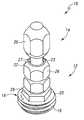
- FIG. 1is a perspective view of a self-contained orthopedic implant component assembly for installing orthopedic implant components onto an orthopedic implant, the self-contained orthopedic implant component assembly embodied as a spinal implant component assembly for installing spinal implant components onto a spinal implant, and particularly for installing a spinal rod holder end cap and spinal rod set screw onto a spinal rod holder assembly;
- FIG. 2is a front plan view of the self-contained spinal implant component assembly of FIG. 1 ;
- FIG. 3is a sectional view of the self-contained spinal implant component assembly of FIG. 1 taken along line 3 - 3 of FIG. 2 ;
- FIG. 4is a top plan view of the self-contained spinal implant component assembly of FIG. 1 taken along line 4 - 4 of FIG. 2 ;
- FIG. 5is a bottom plan view of the self-contained spinal implant component assembly of FIG. 1 taken along line 3 - 3 of FIG. 2 ;
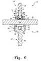
- FIG. 6is a sectional view of a spinal rod holder or vertebral bone screw assembly having a spinal rod holder with a spinal rod therein, the self-contained spinal implant component assembly of FIG. 1 situated thereon and ready to fix the spinal rod into the spinal rod holder with its spinal rod end cap and spinal rod set screw;
- FIG. 7is the sectional view of the spinal rod holder assembly having a spinal rod holder with a spinal rod therein of FIG. 6 with the spinal rod holder end cap and the spinal rod set screw installed therein, the spinal rod holder end cap driver and the spinal rod set screw driver (detachable portions) having been removed therefrom;
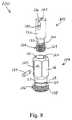
- FIG. 8is an exploded perspective view of another self-contained orthopedic implant component assembly for installing orthopedic implant components onto an orthopedic implant, the self-contained orthopedic implant component assembly embodied as another spinal implant component assembly for installing spinal implant components onto a spinal implant, and particularly for installing a spinal rod holder end cap and spinal rod set screw onto a spinal rod holder assembly;
- FIG. 9is a front plan view of the assembled self-contained spinal implant component assembly of FIG. 8 ;
- FIG. 10is a bottom plan view of the self-contained spinal implant component assembly of FIG. 8 taken along line 10 - 10 of FIG. 9 ;
- FIG. 11is a top plan view of the self-contained spinal implant component assembly of FIG. 8 taken along line 11 - 11 of FIG. 9 ;
- FIG. 12is sectional view of the self-contained spinal implant component assembly of FIG. 8 taken along line 12 - 12 of FIG. 9 ;
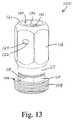
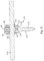
- FIG. 13is an enlarged perspective view of the assembled self-contained spinal implant component assembly of FIG. 8 ;
- FIG. 14is a sectional view of another spinal rod holder or vertebral bone screw assembly having a spinal rod holder with a spinal rod therein, the self-contained spinal implant component assembly of FIG. 8 situated thereon and ready to fix the spinal rod into the spinal rod holder with its spinal rod end cap and spinal rod set screw; and
- FIG. 15is the sectional view of the another spinal rod holder assembly having a spinal rod holder with a spinal rod therein of FIG. 14 with the spinal rod holder end cap and the spinal rod set screw installed therein, the spinal rod holder end cap driver and the spinal rod set screw driver (detachable portions) having been removed therefrom.
- FIGS. 1-5depict various views of an exemplary self-contained orthopedic implant component assembly fashioned in accordance with the present principles.
- the self-contained orthopedic implant component assemblyis embodied in FIGS. 1-5 as a two-part self-contained orthopedic implant component assembly and includes first and second component and component driver formations 12 , 14 .
- the first and second component and component driver formations 12 , 14are configured for independent and/or concerted installation of the first and second components thereof into and/or onto an orthopedic implant and for the removal of the first and second component drivers thereof from the first and second components.
- Each one of the first and second component and component driver formationsis formed by two, detachable portions that are separable from one another after installation of the corresponding component.
- the two-part orthopedic implant component assembly as embodied in FIGS. 1-5has a first combined spinal component and spinal component driver formation, and a second combined spinal component and spinal component driver formation.
- the first and second combined spinal component and spinal component driver formationsare situated relative to one another to provide independent but concerted installation of the first and second spinal components thereof onto and/or into a spinal implant.
- the two-part spinal implant component assembly 10comprises a combined spinal rod holder end cap and spinal rod holder end cap driver 12 , and a combined spinal rod set screw and spinal rod set screw driver 14 , particularly for a spinal rod holder of a spinal rod bone screw assembly (see spinal rod bone screw assembly 50 of FIGS. 6 and 7 ), that provides independent but concerted installation of the spinal rod holder end cap along with the spinal rod set screw onto and/or into the spinal rod holder.
- the two-part orthopedic implant component assembly 10is used for concertedly installing an end cap 16 and a spinal rod set screw 30 into a spinal rod connector head or holder 60 (of the spinal rod connector assembly 50 of FIGS. 6 and 7 ) and locking up a spinal rod (see, e.g., spinal rod 80 of FIGS. 6 and 7 ) in the spinal rod connector assembly of a pedicle screw assembly (see, e.g. pedicle screw assembly 50 of FIGS. 6 and 7 ) independent of the setting of the end cap.
- the various components of the present two-part orthopedic implant component assembly 10are made from a bio-compatible material such as stainless steel or titanium. Other bio-compatible materials, of course, may be used.
- the two-part orthopedic implant component assembly 10consists of a first part end cap assembly 12 (end cap assembly 12 ) and a second part spinal rod set screw assembly 14 (spinal rod set screw assembly 14 ).
- the end cap assembly 12receives the spinal rod set screw assembly 14 both of which are installable or implantable into a spinal rod connector assembly in a concerted manner while allowing for independent fixation of a portion of the end cap assembly 12 relative to the fixation of a portion of the spinal rod set screw assembly 14 .
- the end cap assemblyis characterized by a body defining an end cap 16 and a collar 26 forming a component (end cap) driver.
- the end cap 16is generally annular in shape and has external threads 18 thereon.
- the end cap 16includes a hex portion 20 axially above the threads 18 that is sized to receive a hex driver of a first size.
- the collar 26is configured as a hex shape in like manner as the hex portion 20 of the end cap 16 but of a smaller size than that of the hex portion 20 .
- the collar 26also receives a hex driver but of a second size that is smaller than the hex driver for the hex portion 20 .
- the end cap assembly 12also has a bore 23 that extends axially through the end cap assembly 12 and particularly extends from an end 27 of the collar 26 to an end 22 of the end cap 16 .
- the bore 23includes a threaded portion 24 that axially extends a distance from the end 22 towards the collar 26 .
- a junction or juncture 28 between the collar 26 and the hex portion 20 of the end cap 16 of the end cap assembly 12is reduced in thickness between the inner and outer surface thereof or scored relative to the collar 16 and the hex portion 20 . This allows the collar 26 to be snapped off, broken away or removed from the end cap 16 so as to allow the end cap 16 to remain. The collar 26 thus is and forms a detachable portion of the end cap assembly 12 .
- the spinal rod set screw assembly 14is characterized by a body defining a generally cylindrical shaft 32 having a set screw or set screw portion 30 on one axial end thereof and an elongated hex head 36 on another axial end thereof.
- the elongated hex head 36is sized to that of the collar 36 such that the same sized hex driver can concertedly drive the spinal rod set screw assembly 14 and the end cap assembly 12 .
- the set screw 30has external threads 31 on an axial length thereof that are sized to be threadedly received by the internal threads 24 of the axial bore 23 of the end cap assembly 12 .
- the spinal rod set screw assembly 14is threadedly received in and by the end cap assembly 12 by threaded reception of the set screw 30 in the bore 23 .
- a junction or juncture 34 between the shaft 32 and the set screw 30 of the spinal rod set screw assembly 14is reduced in diameter or is scored. This allows the shaft 32 and the elongated hex head 36 to be snapped off, broken away or removed from the set screw 30 so as to allow the set screw 30 to remain. The shaft 32 and the elongated hex head 36 thus is and forms a detachable portion of the spinal rod set screw assembly 14 .
- the force or bias from the second hex driverremoves both the detachable portion of the end cap assembly 12 and the detachable portion of the spinal rod set screw assembly 14 .
- installation of the two-part orthopedic implant component assembly 10 in one formresults in the breakage of the detachable portion of the end cap assembly 12 before the breakage of the detachable portion of the spinal rod set screw assembly 14 .
- the end cap assembly 12“bottoms out” before the spinal rod set screw assembly “bottoms out.”
- installation of the two-part orthopedic implant component assembly 10results in the breakage of the detachable portion of the end cap assembly 12 and the breakage of the detachable portion of the spinal rod set screw assembly 14 at the same time (simultaneously). In this form, the end cap assembly 12 “bottoms out” at the same time that the spinal rod set screw assembly “bottoms out.”
- installation of the two-part orthopedic implant component assembly 10results in the breakage of the detachable portion of the end cap assembly 12 and the breakage of the detachable portion of the spinal rod set screw assembly 14 at virtually or close to the same time (near simultaneously). In this form, the end cap assembly 12 “bottoms out” just before the spinal rod set screw assembly “bottoms out.”
- FIGS. 6 and 7depict a manner of use of the present two-part orthopedic implant component assembly 10 .
- FIGS. 6 and 7depict a pedicle screw assembly 50 comprised of a pedicle screw 52 and a spinal rod connector assembly 60 .
- the pedicle screw 52is characterized by an externally threaded shaft or shank 54 (of which a lower portion is not shown in FIGS. 6 and 7 ) and a rounded head 56 having a configured socket 58 .
- the spinal rod connector assembly 60is characterized by a “tulip head” 62 having a lower opening 63 sized to allow the shaft 54 of the pedicle screw 52 to extend therethough but to rotatably capture the head 58 of the pedicle screw 52 .
- the tulip head 62has first and second openings 64 and 66 through which a spinal rod 80 extends (of which only a portion is shown in the figures).
- the tulip head 62further has a threaded upper opening 68 that is sized to receive the end cap 16 of the two-part orthopedic implant component assembly 10 (and particularly of the end cap assembly 12 thereof).
- the present inventionmay be and is contemplated for use in other types of implants or orthopedic implants including spinal rod fixation assemblies of types other than the tulip head design shown in FIGS. 6 and 7 (collectively, implant devices) that require multi-torque settings and/or to lock up implant devices requiring two settings to lock in one step.
- implant devicesspinal rod fixation assemblies of types other than the tulip head design shown in FIGS. 6 and 7 (collectively, implant devices) that require multi-torque settings and/or to lock up implant devices requiring two settings to lock in one step.
- the principles of the present inventionapply to orthopedic implant components that provide more than the installation of two components.
- the end cap assembly 12 with the spinal rod set screw assembly 14is threadedly received in the threaded upper opening 68 of the tulip head 62 via a hex driver of appropriate size (not shown) that receives the hex portion 20 of the end cap assembly 12 and the hex head 26 of the spinal rod set screw assembly 14 .
- the spinal rod set screw assembly 14is thus first threaded into the end cap assembly 12 for a particular distance. Via the hex driver, the set screw assembly 14 and the end cap assembly 12 are simultaneously driven downwardly or situated in or on the tulip head 62 .
- the end cap 16abuts, contacts or bottoms out onto the upper end 69 of the taper lock 65 .
- the torque of continued rotation of the hex driverbreaks or snaps off from the hex portion 20 (the detachable portion) of the end cap assembly 12 and into the hex driver.
- the spinal rod set screw assembly 14is driven downward through the end cap assembly 12 until the set screw 30 axially abuts, contacts or bottoms out (compresses) against the spinal rod 80 .
- the torquebreaks or snaps off the hex head 26 (detachable portion) of the spinal rod set screw assembly 14 into the hex driver.
- the two detachable portionsremain in the hex driver to be removed therefrom.
- Removal of the remaining assembly 10is accomplished using the hex portion 20 of the end cap 16 .
- FIGS. 8-13depict various views of another exemplary self-contained orthopedic implant component assembly 100 fashioned in accordance with the present principles.
- the self-contained orthopedic implant component assemblyis embodied in FIGS. 8-13 as a self-contained coupled orthopedic implant component assembly and includes first and second component formations 102 , 104 that are coupled to one another via a driving pin 124 .
- the first and second component formations 102 , 104together with the driving pin 124 , are configured for concerted installation of the first and second components thereof into and/or onto an orthopedic implant and for the removal of the first and second component drivers thereof from the first and second components after installation.
- Each one of the first and second component and component driver formationsis formed by two, detachable portions that are separable from one another for a given amount of torque.
- the coupled spinal implant component assembly 100comprises a combined spinal rod holder end cap and spinal rod holder end cap driver 102 , and a combined spinal rod set screw and spinal rod set screw driver 104 , along with driving pin 124 particularly for a spinal rod holder of a spinal rod bone screw assembly (see spinal rod bone screw assembly 150 of FIGS. 13 and 14 ), that provides independent but concerted installation of the spinal rod holder end cap 106 along with the spinal rod set screw 128 onto and/or into the spinal rod holder.
- the two-part orthopedic implant component assembly 100is used for concertedly installing the end cap 106 and a spinal rod set screw 128 into a spinal rod connector head or holder 160 (of spinal rod connector assembly 160 of FIGS. 13 and 14 ) and then locking up a spinal rod (see the spinal rod 200 of FIGS. 13 and 14 ) therein by the setting of the end cap during continued rotation of the end cap driver.
- the various components of the present coupled orthopedic implant component assembly 100are made from a bio-compatible material such as stainless steel or titanium. Other bio-compatible materials, of course, may be used.
- the coupled orthopedic implant component assembly 100consists of a first part end cap assembly 102 (end cap assembly 102 ) and a second part spinal rod set screw assembly 104 (spinal rod set screw assembly 104 ).
- the end cap assembly 102receives the spinal rod set screw assembly 104 within a bore 120 thereof, both of which are installable or implantable into a spinal rod connector assembly in a concerted manner while allowing for independent fixation of the set screw 128 .
- the end cap assembly 102is characterized by a body defining an end cap 106 with a component driver 116 (i.e. an end cap driver) extending from a collar 117 .
- the end cap 106is generally annular in shape and has external threads 108 thereon.
- a hex portion 110is disposed axially above the threads 108 , and is sized to receive a hex driver of a first size.
- the collar 117is axially above the hex portion 110 and is generally annular.
- the component driver 116is configured as a hex shape for receiving a hex driver (not shown).
- the end cap assembly 102also has a bore 120 that extends axially through the end cap assembly 102 and particularly extends from an end or rim (top) 121 of the driver 116 to an end (bottom) 112 of the end cap 106 .
- the bore 120includes a threaded portion 114 that axially extends a distance from the end 112 towards the driver 116 .
- a junction or juncture 118 between the driver 116 (collar 117 ) and the hex portion 110 of the end cap 106 of the end cap assembly 102is reduced in thickness between the inner and outer surface thereof or scored relative to the driver 116 and the hex portion 110 .
- the driver 116thus is and forms a detachable portion (detachable component driver) of the end cap assembly 102 .
- the driver 116has a bore 122 that extends through opposite sides of the driver 116 (of which only one side of the bore 122 in the driver 116 can be seen) that constitutes a transverse bore 122 such that the bore 122 is in communication with the axial bore 120 of the driver 116 .
- the transverse bore 122is sized to receive the driving or driver pin (i.e. a transverse driving pin) therein and to allow the driving pin 124 to extend through the axial bore 120 and be held by the opposite sides of the driver (see, e.g. FIG. 12 ).
- the driving pinis used to drive the spinal rod set screw assembly 104 in conjunction or concertedly with the driver 116 . This is true when the driver 116 is attached to the end cap 106 and when the driver 116 has been detached from the end cap 106 and is still used for driving the spinal rod set screw assembly 104 for installing the set screw 128 .
- the spinal rod set screw assembly 104is characterized by a body or driver defining a generally cylindrical shaft 130 having the set screw or set screw portion 128 on one axial end thereof.
- the shaft or driver 130is sized for reception into the end cap assembly 102 and particularly, the bore 120 thereof.
- the set screw 128has external threads 129 on an axial length thereof that are sized to be threadedly received by the internal threads 114 of the axial bore 120 of the end cap 106 .
- the spinal rod set screw assembly 104is threadedly received in and by the end cap assembly 102 by threaded reception of the set screw 130 in the bore 120 .
- the shaft or driver 130has an elongated bore 134 extending therethrough from one side of the driver to the other side of the driver (see, e.g., FIG. 12 ).
- the elongated bore 134is generally oval shaped and defines an elongated or axial cavity therein that is sized to receive the driving pin 124 .
- the bore 134is so sized to allow axial movement of the set screw assembly 104 within the end cap assembly 102 with the driving pin installed, thereby coupling the two assemblies 102 , 104 to each other. Since the two assemblies 102 , 104 are coupled to one another, rotation of the end cap assembly 102 will rotate the set screw assembly 104 .
- a junction or juncture 132 between the shaft 130 or shaft reduction portion 133 (collectively, shaft or driver 130 ) and the set screw 128 of the spinal rod set screw assembly 104is reduced in diameter or is scored or otherwise made to allow the shaft 130 to be detached therefrom.
- the junction 132allows the shaft 130 to be snapped off, broken away or removed from the set screw 128 so as to allow the set screw 128 to remain.
- junction 132 of the spinal rod set screw assembly 104 and the junction 118 of the end cap assembly 102are essentially situated radially of one another, and the component driver 116 of the end cap assembly 102 is coupled to the component driver 130 of the set screw assembly 104 , the force or bias from a hex driver on the component driver 116 removes (detaches) both the component driver 116 from the spinal rod end cap assembly 102 and the component driver 130 from the spinal rod set screw assembly 104 .
- Installation of the self-contained coupled orthopedic implant component assembly 100results in the breakage of the detachable portion of the end cap assembly 102 before the breakage of the detachable portion of the spinal rod set screw assembly 104 .
- the end cap assembly 102“bottoms out” before the spinal rod set screw assembly 104 “bottoms out.” While the detached driver 116 is freely rotatable, continued rotation of the driver 116 continues to rotate the set screw assembly 104 (the driver 130 thereof) and thus the set screw 128 thereof until the set screw 128 “bottoms out” on the spinal rod 200 (see, e.g. FIG. 15 ). The driver 130 detaches after bottoming out and continued torque is applied. The set screw assembly 104 axially moves relative to the driving pin 124 by virtue of the elongated slot 134 thereof.
- a slotted driver(not shown) may be used to further install (screw or thread) the set screw assembly 104 and thus the set screw 128 thereof into a final position.
- the bore 134 of the driver 130is axially elongated, the set screw assembly 104 may be driven axially further downward relative to the end cap assembly 102 .
- FIGS. 13 and 14depict a manner of use of the present two-part orthopedic implant component assembly 100 .
- FIGS. 13 and 14depict a pedicle screw assembly 150 comprised of a pedicle screw 152 and a spinal rod holder 160 .
- the pedicle screw 152is characterized by an externally threaded shaft or shank 154 and a rounded head 156 having a configured socket 158 .
- the spinal rod holder 160is characterized by a lower head portion 162 having a lower opening sized to allow the shaft 154 of the pedicle screw 152 to extend there though but to rotatably capture the head 158 of the pedicle screw 152 .
- the holder 160has first and second openings through which a spinal rod 200 extends.
- the holder 160further has an upper head portion 166 with internal threads 167 that are sized to receive the end cap 106
- the present inventionmay be and is contemplated for use in other types of implants or orthopedic implants including spinal rod fixation assemblies of types other than the spinal rod holder/bone screw assembly design shown in FIGS. 13 and 14 (collectively, implant devices) that require multi-torque settings and/or to lock up implant devices requiring two settings to lock in one step.
- implant devicesspinal rod fixation assemblies of types other than the spinal rod holder/bone screw assembly design shown in FIGS. 13 and 14 (collectively, implant devices) that require multi-torque settings and/or to lock up implant devices requiring two settings to lock in one step.
- the principles of the present inventionapply to orthopedic implant components that provide more than the installation of two components.
- the end cap assembly 10 with the spinal rod set screw assembly 104is threadedly received in the threaded upper portion 166 (opening) of the holder 160 .
- the spinal rod set screw assembly 104is thus first threaded into the end cap assembly 102 for a particular distance via a hex driver on the component driver 116 .
- the end cap assembly 102 and the set screw assembly 104are simultaneously (concertedly) driven downwardly or situated in or on the holder 160 .
- the end cap 106abuts, contacts or bottoms out within the holder 160 .
- the angular orientation of the screw 152is thus fixed relative to the holder 162 .
- the predetermined amount of torque of continued rotation of the hex driverbreaks or snaps off the component driver 116 (the detachable portion) of the end cap assembly 10 .
- the spinal rod set screw 128 of the spinal rod set screw assembly 104is driven downward through the end cap assembly 102 until the set screw 128 axially abuts, contacts or bottoms out (compresses) against the spinal rod 200 . This forces the spinal rod 200 axially downward to compress against the openings the holder 160 thereby fixing the spinal rod 200 against the holder 160 .
- the continued torquebreaks or snaps off the component driver 130 (detachable portion) of the spinal rod set screw assembly 104 into the hex driver.
- the two detachable portionsremain in the hex driver to be removed therefrom.
Landscapes
- Health & Medical Sciences (AREA)
- Orthopedic Medicine & Surgery (AREA)
- Life Sciences & Earth Sciences (AREA)
- Neurology (AREA)
- Surgery (AREA)
- Heart & Thoracic Surgery (AREA)
- Engineering & Computer Science (AREA)
- Biomedical Technology (AREA)
- Nuclear Medicine, Radiotherapy & Molecular Imaging (AREA)
- Medical Informatics (AREA)
- Molecular Biology (AREA)
- Animal Behavior & Ethology (AREA)
- General Health & Medical Sciences (AREA)
- Public Health (AREA)
- Veterinary Medicine (AREA)
- Surgical Instruments (AREA)
- Prostheses (AREA)
Abstract
Description
Claims (19)
Priority Applications (1)
| Application Number | Priority Date | Filing Date | Title |
|---|---|---|---|
| US12/412,701US8100909B2 (en) | 2008-03-27 | 2009-03-27 | Self-contained assembly for installation of orthopedic implant components onto an orthopedic implant |
Applications Claiming Priority (2)
| Application Number | Priority Date | Filing Date | Title |
|---|---|---|---|
| US7207008P | 2008-03-27 | 2008-03-27 | |
| US12/412,701US8100909B2 (en) | 2008-03-27 | 2009-03-27 | Self-contained assembly for installation of orthopedic implant components onto an orthopedic implant |
Publications (2)
| Publication Number | Publication Date |
|---|---|
| US20090248030A1 US20090248030A1 (en) | 2009-10-01 |
| US8100909B2true US8100909B2 (en) | 2012-01-24 |
Family
ID=41114783
Family Applications (1)
| Application Number | Title | Priority Date | Filing Date |
|---|---|---|---|
| US12/412,701Active2030-06-25US8100909B2 (en) | 2008-03-27 | 2009-03-27 | Self-contained assembly for installation of orthopedic implant components onto an orthopedic implant |
Country Status (2)
| Country | Link |
|---|---|
| US (1) | US8100909B2 (en) |
| WO (1) | WO2009120985A2 (en) |
Cited By (11)
| Publication number | Priority date | Publication date | Assignee | Title |
|---|---|---|---|---|
| US20100160981A1 (en)* | 2008-12-22 | 2010-06-24 | Butler Michael S | Posterior Cervical Cross Connector Assemblies |
| US20110213424A1 (en)* | 2009-08-12 | 2011-09-01 | Lutz Biedermann | receiving part for receiving a rod for coupling the rod to a bone anchoring element |
| US20140135839A1 (en)* | 2012-11-09 | 2014-05-15 | Blackstone Medical, Inc. | Percutaneous modular head-to-head cross connector |
| US8956361B2 (en) | 2011-12-19 | 2015-02-17 | Amendia, Inc. | Extended tab bone screw system |
| US9603634B1 (en) | 2015-11-13 | 2017-03-28 | Amendia, Inc. | Percutaneous rod-to-rod cross connector |
| US9707015B2 (en) | 2014-01-14 | 2017-07-18 | Life Spine, Inc. | Implant for immobilizing cervical vertebrae |
| USD797167S1 (en)* | 2015-07-02 | 2017-09-12 | Damian Rodriguez | Two-part taper lock assembly |
| US9795422B2 (en) | 2016-01-06 | 2017-10-24 | Aesculap Implant Systems, Llc | Rod inserter, system and method |
| US9968387B2 (en) | 2016-01-06 | 2018-05-15 | Aesculap Implant Systems, Llc | Rod inserter, system and method |
| US10039573B2 (en) | 2013-07-25 | 2018-08-07 | Amendia, Inc. | Percutaneous pedicle screw revision system |
| US11298163B2 (en)* | 2019-04-22 | 2022-04-12 | Warsaw Orthopedic, Inc. | Internal breakoff set screw and driver |
Families Citing this family (54)
| Publication number | Priority date | Publication date | Assignee | Title |
|---|---|---|---|---|
| US7833250B2 (en) | 2004-11-10 | 2010-11-16 | Jackson Roger P | Polyaxial bone screw with helically wound capture connection |
| US7862587B2 (en) | 2004-02-27 | 2011-01-04 | Jackson Roger P | Dynamic stabilization assemblies, tool set and method |
| US8876868B2 (en) | 2002-09-06 | 2014-11-04 | Roger P. Jackson | Helical guide and advancement flange with radially loaded lip |
| WO2006052796A2 (en) | 2004-11-10 | 2006-05-18 | Jackson Roger P | Helical guide and advancement flange with break-off extensions |
| US7621918B2 (en) | 2004-11-23 | 2009-11-24 | Jackson Roger P | Spinal fixation tool set and method |
| US7377923B2 (en) | 2003-05-22 | 2008-05-27 | Alphatec Spine, Inc. | Variable angle spinal screw assembly |
| US8398682B2 (en) | 2003-06-18 | 2013-03-19 | Roger P. Jackson | Polyaxial bone screw assembly |
| US7766915B2 (en) | 2004-02-27 | 2010-08-03 | Jackson Roger P | Dynamic fixation assemblies with inner core and outer coil-like member |
| US8377102B2 (en) | 2003-06-18 | 2013-02-19 | Roger P. Jackson | Polyaxial bone anchor with spline capture connection and lower pressure insert |
| US8137386B2 (en) | 2003-08-28 | 2012-03-20 | Jackson Roger P | Polyaxial bone screw apparatus |
| US8926670B2 (en) | 2003-06-18 | 2015-01-06 | Roger P. Jackson | Polyaxial bone screw assembly |
| US7776067B2 (en) | 2005-05-27 | 2010-08-17 | Jackson Roger P | Polyaxial bone screw with shank articulation pressure insert and method |
| US7527638B2 (en) | 2003-12-16 | 2009-05-05 | Depuy Spine, Inc. | Methods and devices for minimally invasive spinal fixation element placement |
| US7179261B2 (en) | 2003-12-16 | 2007-02-20 | Depuy Spine, Inc. | Percutaneous access devices and bone anchor assemblies |
| US11419642B2 (en) | 2003-12-16 | 2022-08-23 | Medos International Sarl | Percutaneous access devices and bone anchor assemblies |
| US8152810B2 (en) | 2004-11-23 | 2012-04-10 | Jackson Roger P | Spinal fixation tool set and method |
| JP2007525274A (en) | 2004-02-27 | 2007-09-06 | ロジャー・ピー・ジャクソン | Orthopedic implant rod reduction instrument set and method |
| US11241261B2 (en) | 2005-09-30 | 2022-02-08 | Roger P Jackson | Apparatus and method for soft spinal stabilization using a tensionable cord and releasable end structure |
| US7160300B2 (en) | 2004-02-27 | 2007-01-09 | Jackson Roger P | Orthopedic implant rod reduction tool set and method |
| US8926672B2 (en) | 2004-11-10 | 2015-01-06 | Roger P. Jackson | Splay control closure for open bone anchor |
| US8308782B2 (en) | 2004-11-23 | 2012-11-13 | Jackson Roger P | Bone anchors with longitudinal connecting member engaging inserts and closures for fixation and optional angulation |
| US9168069B2 (en) | 2009-06-15 | 2015-10-27 | Roger P. Jackson | Polyaxial bone anchor with pop-on shank and winged insert with lower skirt for engaging a friction fit retainer |
| US9980753B2 (en) | 2009-06-15 | 2018-05-29 | Roger P Jackson | pivotal anchor with snap-in-place insert having rotation blocking extensions |
| WO2006057837A1 (en) | 2004-11-23 | 2006-06-01 | Jackson Roger P | Spinal fixation tool attachment structure |
| US8444681B2 (en) | 2009-06-15 | 2013-05-21 | Roger P. Jackson | Polyaxial bone anchor with pop-on shank, friction fit retainer and winged insert |
| US10076361B2 (en) | 2005-02-22 | 2018-09-18 | Roger P. Jackson | Polyaxial bone screw with spherical capture, compression and alignment and retention structures |
| US7901437B2 (en) | 2007-01-26 | 2011-03-08 | Jackson Roger P | Dynamic stabilization member with molded connection |
| CA2670988C (en) | 2006-12-08 | 2014-03-25 | Roger P. Jackson | Tool system for dynamic spinal implants |
| US10792074B2 (en) | 2007-01-22 | 2020-10-06 | Roger P. Jackson | Pivotal bone anchor assemly with twist-in-place friction fit insert |
| US8979904B2 (en) | 2007-05-01 | 2015-03-17 | Roger P Jackson | Connecting member with tensioned cord, low profile rigid sleeve and spacer with torsion control |
| AU2010260521C1 (en) | 2008-08-01 | 2013-08-01 | Roger P. Jackson | Longitudinal connecting member with sleeved tensioned cords |
| US8216237B2 (en)* | 2009-06-04 | 2012-07-10 | Edwards Scott G | Intramedullary device assembly and associated method |
| US11229457B2 (en) | 2009-06-15 | 2022-01-25 | Roger P. Jackson | Pivotal bone anchor assembly with insert tool deployment |
| US9668771B2 (en) | 2009-06-15 | 2017-06-06 | Roger P Jackson | Soft stabilization assemblies with off-set connector |
| US8998959B2 (en) | 2009-06-15 | 2015-04-07 | Roger P Jackson | Polyaxial bone anchors with pop-on shank, fully constrained friction fit retainer and lock and release insert |
| CN103826560A (en) | 2009-06-15 | 2014-05-28 | 罗杰.P.杰克逊 | Polyaxial Bone Anchor with Socket Stem and Winged Inserts with Friction Fit Compression Collars |
| EP2485654B1 (en) | 2009-10-05 | 2021-05-05 | Jackson P. Roger | Polyaxial bone anchor with non-pivotable retainer and pop-on shank, some with friction fit |
| US12383311B2 (en) | 2010-05-14 | 2025-08-12 | Roger P. Jackson | Pivotal bone anchor assembly and method for use thereof |
| AU2011324058A1 (en) | 2010-11-02 | 2013-06-20 | Roger P. Jackson | Polyaxial bone anchor with pop-on shank and pivotable retainer |
| US20120116458A1 (en)* | 2010-11-08 | 2012-05-10 | Warsaw Orthopedic, Inc. | Modular pivotable screw assembly and method |
| JP5865479B2 (en) | 2011-03-24 | 2016-02-17 | ロジャー・ピー・ジャクソン | Multiaxial bone anchor with compound joint and pop-mounted shank |
| US8911479B2 (en) | 2012-01-10 | 2014-12-16 | Roger P. Jackson | Multi-start closures for open implants |
| ES2549634T3 (en)* | 2012-05-31 | 2015-10-30 | Biedermann Technologies Gmbh & Co. Kg | Polyaxial bone anchoring device |
| US8911478B2 (en) | 2012-11-21 | 2014-12-16 | Roger P. Jackson | Splay control closure for open bone anchor |
| US10058354B2 (en) | 2013-01-28 | 2018-08-28 | Roger P. Jackson | Pivotal bone anchor assembly with frictional shank head seating surfaces |
| US8852239B2 (en) | 2013-02-15 | 2014-10-07 | Roger P Jackson | Sagittal angle screw with integral shank and receiver |
| US9566092B2 (en) | 2013-10-29 | 2017-02-14 | Roger P. Jackson | Cervical bone anchor with collet retainer and outer locking sleeve |
| US20150119945A1 (en)* | 2013-10-31 | 2015-04-30 | Orthopaedic International, Inc. | Set screw to minimize splaying in pedicle screws |
| US9717533B2 (en) | 2013-12-12 | 2017-08-01 | Roger P. Jackson | Bone anchor closure pivot-splay control flange form guide and advancement structure |
| US9451993B2 (en) | 2014-01-09 | 2016-09-27 | Roger P. Jackson | Bi-radial pop-on cervical bone anchor |
| US10064658B2 (en) | 2014-06-04 | 2018-09-04 | Roger P. Jackson | Polyaxial bone anchor with insert guides |
| US9597119B2 (en) | 2014-06-04 | 2017-03-21 | Roger P. Jackson | Polyaxial bone anchor with polymer sleeve |
| FR3052658A1 (en)* | 2016-06-21 | 2017-12-22 | Innoprod Medical | MEDICAL IMPLANT FOR TARGETED INJECTION |
| US20180228516A1 (en)* | 2017-02-14 | 2018-08-16 | Warsaw Orthopedic, Inc. | Spinal implant system and method |
Citations (13)
| Publication number | Priority date | Publication date | Assignee | Title |
|---|---|---|---|---|
| US4946458A (en) | 1986-04-25 | 1990-08-07 | Harms Juergen | Pedicle screw |
| US5941885A (en) | 1996-10-08 | 1999-08-24 | Jackson; Roger P. | Tools for use in installing osteosynthesis apparatus utilizing set screw with break-off head |
| US20040039383A1 (en) | 2002-08-26 | 2004-02-26 | Jackson Roger P | Nested closure plug and set screw with break-off heads |
| US20080077139A1 (en)* | 2002-10-30 | 2008-03-27 | Landry Michael E | Spinal stabilization systems with quick-connect sleeve assemblies for use in surgical procedures |
| US20090005787A1 (en)* | 2007-06-28 | 2009-01-01 | Angela Crall | Device and system for implanting polyaxial bone fasteners |
| US20090248089A1 (en)* | 2008-03-25 | 2009-10-01 | Jacofsky Marc C | Spinal facet fixation device |
| US20090254125A1 (en)* | 2008-04-03 | 2009-10-08 | Daniel Predick | Top Loading Polyaxial Spine Screw Assembly With One Step Lockup |
| US20090281579A1 (en)* | 2008-05-08 | 2009-11-12 | Aesculap Implant Systems, Inc. | Minimally invasive spinal stabilization system |
| US20100057136A1 (en)* | 2008-09-02 | 2010-03-04 | Heiges Bradley A | Modular pedicle screw system with tap and screw driver device |
| US20100094349A1 (en)* | 2004-08-27 | 2010-04-15 | Michael Hammer | Multi-Axial Connection System |
| US20100168796A1 (en)* | 2008-07-29 | 2010-07-01 | Kenneth Arden Eliasen | Bone anchoring member with clamp mechanism |
| US20100198272A1 (en)* | 2007-07-20 | 2010-08-05 | Thomas Keyer | Polyaxial bone fixation element |
| US20100204735A1 (en)* | 2009-02-11 | 2010-08-12 | Gephart Matthew P | Wide Angulation Coupling Members For Bone Fixation System |
Family Cites Families (1)
| Publication number | Priority date | Publication date | Assignee | Title |
|---|---|---|---|---|
| AU2001267863A1 (en)* | 2000-06-29 | 2002-01-08 | Japan Absorbent Technology Institute | Absorber product |
- 2009
- 2009-03-27USUS12/412,701patent/US8100909B2/enactiveActive
- 2009-03-27WOPCT/US2009/038602patent/WO2009120985A2/enactiveApplication Filing
Patent Citations (13)
| Publication number | Priority date | Publication date | Assignee | Title |
|---|---|---|---|---|
| US4946458A (en) | 1986-04-25 | 1990-08-07 | Harms Juergen | Pedicle screw |
| US5941885A (en) | 1996-10-08 | 1999-08-24 | Jackson; Roger P. | Tools for use in installing osteosynthesis apparatus utilizing set screw with break-off head |
| US20040039383A1 (en) | 2002-08-26 | 2004-02-26 | Jackson Roger P | Nested closure plug and set screw with break-off heads |
| US20080077139A1 (en)* | 2002-10-30 | 2008-03-27 | Landry Michael E | Spinal stabilization systems with quick-connect sleeve assemblies for use in surgical procedures |
| US20100094349A1 (en)* | 2004-08-27 | 2010-04-15 | Michael Hammer | Multi-Axial Connection System |
| US20090005787A1 (en)* | 2007-06-28 | 2009-01-01 | Angela Crall | Device and system for implanting polyaxial bone fasteners |
| US20100198272A1 (en)* | 2007-07-20 | 2010-08-05 | Thomas Keyer | Polyaxial bone fixation element |
| US20090248089A1 (en)* | 2008-03-25 | 2009-10-01 | Jacofsky Marc C | Spinal facet fixation device |
| US20090254125A1 (en)* | 2008-04-03 | 2009-10-08 | Daniel Predick | Top Loading Polyaxial Spine Screw Assembly With One Step Lockup |
| US20090281579A1 (en)* | 2008-05-08 | 2009-11-12 | Aesculap Implant Systems, Inc. | Minimally invasive spinal stabilization system |
| US20100168796A1 (en)* | 2008-07-29 | 2010-07-01 | Kenneth Arden Eliasen | Bone anchoring member with clamp mechanism |
| US20100057136A1 (en)* | 2008-09-02 | 2010-03-04 | Heiges Bradley A | Modular pedicle screw system with tap and screw driver device |
| US20100204735A1 (en)* | 2009-02-11 | 2010-08-12 | Gephart Matthew P | Wide Angulation Coupling Members For Bone Fixation System |
Cited By (24)
| Publication number | Priority date | Publication date | Assignee | Title |
|---|---|---|---|---|
| US8246665B2 (en)* | 2008-12-22 | 2012-08-21 | Life Spine, Inc. | Posterior cervical cross connector assemblies |
| US20100160981A1 (en)* | 2008-12-22 | 2010-06-24 | Butler Michael S | Posterior Cervical Cross Connector Assemblies |
| US11931079B2 (en) | 2009-08-12 | 2024-03-19 | Biedermann Technologies Gmbh & Co. Kg | Receiving part for receiving a rod for coupling the rod to a bone anchoring element |
| US20110213424A1 (en)* | 2009-08-12 | 2011-09-01 | Lutz Biedermann | receiving part for receiving a rod for coupling the rod to a bone anchoring element |
| US9895172B2 (en)* | 2009-08-12 | 2018-02-20 | Biedermann Technologies Gmbh & Co. Kg | Receiving part for receiving a rod for coupling the rod to a bone anchoring element |
| US11160582B2 (en) | 2009-08-12 | 2021-11-02 | Biedermann Technologies Gmbh & Co. Kg | Receiving part for receiving a rod for coupling the rod to a bone anchoring element |
| US9283000B2 (en)* | 2009-08-12 | 2016-03-15 | Biedermann Technologies Gmbh & Co. Kg | Receiving part for receiving a rod for coupling the rod to a bone anchoring element |
| US10426522B2 (en) | 2009-08-12 | 2019-10-01 | Biedermann Technologies Gmbh & Co. Kg | Receiving part for receiving a rod for coupling the rod to a bone anchoring element |
| US12408951B2 (en) | 2009-08-12 | 2025-09-09 | Biedermann Technologies Gmbh & Co. Kg | Receiving part for receiving a rod for coupling the rod to a bone anchoring element |
| US8956361B2 (en) | 2011-12-19 | 2015-02-17 | Amendia, Inc. | Extended tab bone screw system |
| US9439684B2 (en)* | 2012-11-09 | 2016-09-13 | Amendia, Inc. | Percutaneous modular head-to-head cross connector |
| US20150230830A1 (en)* | 2012-11-09 | 2015-08-20 | Neurovent Llc | Percutaneous modular head-to-head cross connector |
| US9023087B2 (en)* | 2012-11-09 | 2015-05-05 | Blackstone Medical, Inc. | Percutaneous modular head-to-head cross connector |
| US20140135839A1 (en)* | 2012-11-09 | 2014-05-15 | Blackstone Medical, Inc. | Percutaneous modular head-to-head cross connector |
| US10888355B2 (en) | 2013-07-25 | 2021-01-12 | Spinal Elements, Inc. | Percutaneous pedicle screw revision system |
| US10039573B2 (en) | 2013-07-25 | 2018-08-07 | Amendia, Inc. | Percutaneous pedicle screw revision system |
| US10512488B2 (en) | 2014-01-14 | 2019-12-24 | Life Spine, Inc. | Implant for immobilizing cervical vertebrae |
| US10166046B2 (en) | 2014-01-14 | 2019-01-01 | Life Spine, Inc. | Implant for immobilizing cervical vertebrae |
| US9707015B2 (en) | 2014-01-14 | 2017-07-18 | Life Spine, Inc. | Implant for immobilizing cervical vertebrae |
| USD797167S1 (en)* | 2015-07-02 | 2017-09-12 | Damian Rodriguez | Two-part taper lock assembly |
| US9603634B1 (en) | 2015-11-13 | 2017-03-28 | Amendia, Inc. | Percutaneous rod-to-rod cross connector |
| US9968387B2 (en) | 2016-01-06 | 2018-05-15 | Aesculap Implant Systems, Llc | Rod inserter, system and method |
| US9795422B2 (en) | 2016-01-06 | 2017-10-24 | Aesculap Implant Systems, Llc | Rod inserter, system and method |
| US11298163B2 (en)* | 2019-04-22 | 2022-04-12 | Warsaw Orthopedic, Inc. | Internal breakoff set screw and driver |
Also Published As
| Publication number | Publication date |
|---|---|
| WO2009120985A2 (en) | 2009-10-01 |
| US20090248030A1 (en) | 2009-10-01 |
| WO2009120985A3 (en) | 2009-12-30 |
Similar Documents
| Publication | Publication Date | Title |
|---|---|---|
| US8100909B2 (en) | Self-contained assembly for installation of orthopedic implant components onto an orthopedic implant | |
| US8246665B2 (en) | Posterior cervical cross connector assemblies | |
| US9095386B2 (en) | Spinal rod guide for a vertebral screw spinal rod connector assembly | |
| US9936986B2 (en) | Systems and methods for spinal rod insertion and reduction | |
| US9247965B2 (en) | Polyaxial bone anchoring device with enlarged pivot angle | |
| US20090254125A1 (en) | Top Loading Polyaxial Spine Screw Assembly With One Step Lockup | |
| US9277938B2 (en) | Polyaxial bone anchoring system | |
| US9877747B2 (en) | Spine stabilization system | |
| US20060036252A1 (en) | Polyaxial screw | |
| US8216237B2 (en) | Intramedullary device assembly and associated method | |
| US20110160775A1 (en) | Locking Device And Method Employing A Posted Member To Control Positioning Of A Stabilization Member Of A Bone Stabilization System | |
| US20240268866A1 (en) | Bone anchor housing limiter | |
| KR20110112306A (en) | Rod Conquer Device for Chiropractic Surgery | |
| EP2772212B1 (en) | Instrument for inserting a bone anchoring element and system of such an instrument and a polyaxial bone anchoring element | |
| WO2005037067A2 (en) | Polyaxial bone anchor and method of spinal fixation | |
| WO2006124987A1 (en) | Axial compression fastener system | |
| US20050245933A1 (en) | Multi coaxial screw system | |
| US20070288003A1 (en) | Locking device and method, for use in a bone stabilization system, employing a break-away interface member rigidly coupled to a seating member | |
| US10470802B2 (en) | Revision assembly for an item of vertebral osteosynthesis equipment | |
| FI3565491T3 (en) | Bone screw for osteosynthesis device, assembly formed by a screw, a connector and a nut, and kit comprising at least one such assembly |
Legal Events
| Date | Code | Title | Description |
|---|---|---|---|
| AS | Assignment | Owner name:LIFE SPINE, INC., ILLINOIS Free format text:ASSIGNMENT OF ASSIGNORS INTEREST;ASSIGNORS:BUTLER, MICHAEL S.;PREDICK, DANIEL;REEL/FRAME:022464/0422 Effective date:20090324 | |
| AS | Assignment | Owner name:SILICON VALLEY BANK, COLORADO Free format text:SECURITY AGREEMENT;ASSIGNOR:LIFE SPINE, INC.;REEL/FRAME:025846/0010 Effective date:20110208 | |
| AS | Assignment | Owner name:LIFE SPINE, INC., ILLINOIS Free format text:RELEASE BY SECURED PARTY;ASSIGNOR:SILICON VALLEY BANK;REEL/FRAME:026944/0931 Effective date:20110920 | |
| STCF | Information on status: patent grant | Free format text:PATENTED CASE | |
| AS | Assignment | Owner name:BMO HARRIS BANK N.A., ILLINOIS Free format text:SECURITY INTEREST;ASSIGNOR:LIFE SPINE, INC.;REEL/FRAME:033276/0408 Effective date:20140626 | |
| FPAY | Fee payment | Year of fee payment:4 | |
| AS | Assignment | Owner name:MB FINANCIAL BANK, N.A., ILLINOIS Free format text:SECURITY INTEREST;ASSIGNORS:LIFE SPINE, INC.;GIZMO MEDICAL, LLC;REEL/FRAME:040491/0791 Effective date:20161025 Owner name:ST CLOUD CAPITAL PARTNERS III SBIC, LP, CALIFORNIA Free format text:SECURITY INTEREST;ASSIGNORS:GIZMO MEDICAL, LLC;LIFE SPINE, INC.;REEL/FRAME:040497/0926 Effective date:20161025 | |
| AS | Assignment | Owner name:LIFE SPINE, INC., ILLINOIS Free format text:RELEASE BY SECURED PARTY;ASSIGNOR:BMO HARRIS BANK N.A.;REEL/FRAME:040511/0788 Effective date:20161028 | |
| AS | Assignment | Owner name:ST CLOUD CAPITAL PARTNERS III SBIC, LP, CALIFORNIA Free format text:CORRECTIVE ASSIGNMENT TO CORRECT THE LEGAL DOCUMENT ATTACHED TO THE FILING PREVIOUSLY RECORDED AT REEL: 040497 FRAME: 0926. ASSIGNOR(S) HEREBY CONFIRMS THE SECURITY INTEREST;ASSIGNORS:GIZMO MEDIACL, LLC;LIFE SPINE, INC.;REEL/FRAME:042084/0917 Effective date:20161025 Owner name:ST CLOUD CAPITAL PARTNERS III SBIC, LP, CALIFORNIA Free format text:CORRECTIVE ASSIGNMENT TO CORRECT THE LEGAL DOCUMENT PREVIOUSLY RECORDED AT REEL: 040497 FRAME: 0926. ASSIGNOR(S) HEREBY CONFIRMS THE ASSIGNMENT;ASSIGNORS:GIZMO MEDICAL, LLC;LIFE SPINE, INC.;REEL/FRAME:042243/0607 Effective date:20161025 | |
| FEPP | Fee payment procedure | Free format text:MAINTENANCE FEE REMINDER MAILED (ORIGINAL EVENT CODE: REM.); ENTITY STATUS OF PATENT OWNER: SMALL ENTITY | |
| FEPP | Fee payment procedure | Free format text:7.5 YR SURCHARGE - LATE PMT W/IN 6 MO, SMALL ENTITY (ORIGINAL EVENT CODE: M2555); ENTITY STATUS OF PATENT OWNER: SMALL ENTITY | |
| MAFP | Maintenance fee payment | Free format text:PAYMENT OF MAINTENANCE FEE, 8TH YR, SMALL ENTITY (ORIGINAL EVENT CODE: M2552); ENTITY STATUS OF PATENT OWNER: SMALL ENTITY Year of fee payment:8 | |
| AS | Assignment | Owner name:LIFE SPINE, INC., ILLINOIS Free format text:RELEASE BY SECURED PARTY;ASSIGNOR:FIFTH THIRD BANK, NATIONAL ASSOCIATION;REEL/FRAME:054843/0755 Effective date:20201218 Owner name:GIZMO MEDICAL, LLC, ILLINOIS Free format text:RELEASE BY SECURED PARTY;ASSIGNOR:FIFTH THIRD BANK, NATIONAL ASSOCIATION;REEL/FRAME:054843/0755 Effective date:20201218 Owner name:ST. CLOUD CAPITAL PARTNERS III SBIC, LP, CALIFORNIA Free format text:SECURITY INTEREST;ASSIGNORS:LIFE SPINE, INC.;GIZMO MEDICAL, LLC;REEL/FRAME:054844/0239 Effective date:20201218 | |
| AS | Assignment | Owner name:ASSOCIATED BANK, NATIONAL ASSOCIATION, AS AGENT, ILLINOIS Free format text:SECURITY INTEREST;ASSIGNOR:LIFE SPINE, INC.;REEL/FRAME:056728/0438 Effective date:20210630 | |
| AS | Assignment | Owner name:LIFE SPINE, INC., ILLINOIS Free format text:RELEASE BY SECURED PARTY;ASSIGNOR:ASSOCIATED BANK, NATIONAL ASSOCIATION;REEL/FRAME:064275/0446 Effective date:20230526 | |
| FEPP | Fee payment procedure | Free format text:MAINTENANCE FEE REMINDER MAILED (ORIGINAL EVENT CODE: REM.); ENTITY STATUS OF PATENT OWNER: SMALL ENTITY | |
| FEPP | Fee payment procedure | Free format text:11.5 YR SURCHARGE- LATE PMT W/IN 6 MO, SMALL ENTITY (ORIGINAL EVENT CODE: M2556); ENTITY STATUS OF PATENT OWNER: SMALL ENTITY | |
| MAFP | Maintenance fee payment | Free format text:PAYMENT OF MAINTENANCE FEE, 12TH YR, SMALL ENTITY (ORIGINAL EVENT CODE: M2553); ENTITY STATUS OF PATENT OWNER: SMALL ENTITY Year of fee payment:12 |