US8100881B2 - Flexible medical device for clot removal from small vessels - Google Patents
Flexible medical device for clot removal from small vesselsDownload PDFInfo
- Publication number
- US8100881B2 US8100881B2US12/535,229US53522909AUS8100881B2US 8100881 B2US8100881 B2US 8100881B2US 53522909 AUS53522909 AUS 53522909AUS 8100881 B2US8100881 B2US 8100881B2
- Authority
- US
- United States
- Prior art keywords
- wire
- strands
- delivery member
- wire strands
- polygon
- Prior art date
- Legal status (The legal status is an assumption and is not a legal conclusion. Google has not performed a legal analysis and makes no representation as to the accuracy of the status listed.)
- Active, expires
Links
- 229910052751metalInorganic materials0.000claimsabstractdescription45
- 239000002184metalSubstances0.000claimsabstractdescription45
- 229920000642polymerPolymers0.000claimsabstractdescription25
- 239000003527fibrinolytic agentSubstances0.000claimsabstractdescription20
- 239000000463materialSubstances0.000claimsdescription21
- 238000001802infusionMethods0.000claimsdescription14
- 230000003480fibrinolytic effectEffects0.000claimsdescription9
- 239000000203mixtureSubstances0.000claimsdescription6
- KDLHZDBZIXYQEI-UHFFFAOYSA-NPalladiumChemical compound[Pd]KDLHZDBZIXYQEI-UHFFFAOYSA-N0.000claimsdescription4
- BASFCYQUMIYNBI-UHFFFAOYSA-NplatinumChemical compound[Pt]BASFCYQUMIYNBI-UHFFFAOYSA-N0.000claimsdescription4
- 229920002313fluoropolymerPolymers0.000claimsdescription3
- 239000004811fluoropolymerSubstances0.000claimsdescription3
- PCHJSUWPFVWCPO-UHFFFAOYSA-NgoldChemical compound[Au]PCHJSUWPFVWCPO-UHFFFAOYSA-N0.000claimsdescription3
- 229910052737goldInorganic materials0.000claimsdescription3
- 239000010931goldSubstances0.000claimsdescription3
- 229920000098polyolefinPolymers0.000claimsdescription3
- 229920001971elastomerPolymers0.000claimsdescription2
- 239000000806elastomerSubstances0.000claimsdescription2
- 238000002594fluoroscopyMethods0.000claimsdescription2
- 229910052741iridiumInorganic materials0.000claimsdescription2
- GKOZUEZYRPOHIO-UHFFFAOYSA-Niridium atomChemical compound[Ir]GKOZUEZYRPOHIO-UHFFFAOYSA-N0.000claimsdescription2
- 229910052763palladiumInorganic materials0.000claimsdescription2
- 229910052697platinumInorganic materials0.000claimsdescription2
- 229910052703rhodiumInorganic materials0.000claimsdescription2
- 239000010948rhodiumSubstances0.000claimsdescription2
- MHOVAHRLVXNVSD-UHFFFAOYSA-Nrhodium atomChemical compound[Rh]MHOVAHRLVXNVSD-UHFFFAOYSA-N0.000claimsdescription2
- 238000000034methodMethods0.000abstractdescription13
- 208000007536ThrombosisDiseases0.000abstractdescription10
- 230000002792vascularEffects0.000abstractdescription5
- 210000004872soft tissueAnatomy0.000abstractdescription3
- 229940079593drugDrugs0.000abstractdescription2
- 239000003814drugSubstances0.000abstractdescription2
- -1ethylene-tetrafluoroethyleneChemical group0.000description10
- 210000004204blood vesselAnatomy0.000description9
- 230000020764fibrinolysisEffects0.000description6
- 238000007917intracranial administrationMethods0.000description6
- 238000000576coating methodMethods0.000description5
- 238000004804windingMethods0.000description5
- 239000011248coating agentSubstances0.000description4
- 210000005166vasculatureAnatomy0.000description4
- 238000010438heat treatmentMethods0.000description3
- 238000012986modificationMethods0.000description3
- 230000004048modificationEffects0.000description3
- 229920001343polytetrafluoroethylenePolymers0.000description3
- 239000004810polytetrafluoroethyleneSubstances0.000description3
- 238000012546transferMethods0.000description3
- 102000009123FibrinHuman genes0.000description2
- 108010073385FibrinProteins0.000description2
- BWGVNKXGVNDBDI-UHFFFAOYSA-NFibrin monomerChemical compoundCNC(=O)CNC(=O)CNBWGVNKXGVNDBDI-UHFFFAOYSA-N0.000description2
- 239000004812Fluorinated ethylene propyleneSubstances0.000description2
- HTTJABKRGRZYRN-UHFFFAOYSA-NHeparinChemical compoundOC1C(NC(=O)C)C(O)OC(COS(O)(=O)=O)C1OC1C(OS(O)(=O)=O)C(O)C(OC2C(C(OS(O)(=O)=O)C(OC3C(C(O)C(O)C(O3)C(O)=O)OS(O)(=O)=O)C(CO)O2)NS(O)(=O)=O)C(C(O)=O)O1HTTJABKRGRZYRN-UHFFFAOYSA-N0.000description2
- VYPSYNLAJGMNEJ-UHFFFAOYSA-NSilicium dioxideChemical compoundO=[Si]=OVYPSYNLAJGMNEJ-UHFFFAOYSA-N0.000description2
- 102100033571Tissue-type plasminogen activatorHuman genes0.000description2
- 238000005452bendingMethods0.000description2
- 210000004556brainAnatomy0.000description2
- 229920001577copolymerPolymers0.000description2
- 230000007423decreaseEffects0.000description2
- 238000004090dissolutionMethods0.000description2
- 239000013013elastic materialSubstances0.000description2
- 229920000840ethylene tetrafluoroethylene copolymerPolymers0.000description2
- 229950003499fibrinDrugs0.000description2
- 229960002897heparinDrugs0.000description2
- 229920000669heparinPolymers0.000description2
- 238000003754machiningMethods0.000description2
- 229920009441perflouroethylene propylenePolymers0.000description2
- 239000002987primer (paints)Substances0.000description2
- 238000007789sealingMethods0.000description2
- BFKJFAAPBSQJPD-UHFFFAOYSA-NtetrafluoroetheneChemical groupFC(F)=C(F)FBFKJFAAPBSQJPD-UHFFFAOYSA-N0.000description2
- SMZOUWXMTYCWNB-UHFFFAOYSA-N2-(2-methoxy-5-methylphenyl)ethanamineChemical compoundCOC1=CC=C(C)C=C1CCNSMZOUWXMTYCWNB-UHFFFAOYSA-N0.000description1
- NIXOWILDQLNWCW-UHFFFAOYSA-N2-Propenoic acidNatural productsOC(=O)C=CNIXOWILDQLNWCW-UHFFFAOYSA-N0.000description1
- HRPVXLWXLXDGHG-UHFFFAOYSA-NAcrylamideChemical compoundNC(=O)C=CHRPVXLWXLXDGHG-UHFFFAOYSA-N0.000description1
- 241001631457CannulaSpecies0.000description1
- 229920002134Carboxymethyl cellulosePolymers0.000description1
- 241000218202CoptisSpecies0.000description1
- 235000002991Coptis groenlandicaNutrition0.000description1
- 241001272720Medialuna californiensisSpecies0.000description1
- 102000013566PlasminogenHuman genes0.000description1
- 108010051456PlasminogenProteins0.000description1
- 229920003171Poly (ethylene oxide)Polymers0.000description1
- 239000004698PolyethyleneSubstances0.000description1
- 229920002873PolyethyleniminePolymers0.000description1
- 239000004743PolypropyleneSubstances0.000description1
- 229910001260Pt alloyInorganic materials0.000description1
- 108090000373Tissue Plasminogen ActivatorProteins0.000description1
- 108050006955Tissue-type plasminogen activatorProteins0.000description1
- RTAQQCXQSZGOHL-UHFFFAOYSA-NTitaniumChemical compound[Ti]RTAQQCXQSZGOHL-UHFFFAOYSA-N0.000description1
- 229910045601alloyInorganic materials0.000description1
- 239000000956alloySubstances0.000description1
- 230000010100anticoagulationEffects0.000description1
- 230000000740bleeding effectEffects0.000description1
- 230000017531blood circulationEffects0.000description1
- 239000001768carboxy methyl celluloseSubstances0.000description1
- 235000010948carboxy methyl celluloseNutrition0.000description1
- 239000008112carboxymethyl-celluloseSubstances0.000description1
- 210000000269carotid artery externalAnatomy0.000description1
- 210000004004carotid artery internalAnatomy0.000description1
- 239000002131composite materialSubstances0.000description1
- 230000006835compressionEffects0.000description1
- 238000007906compressionMethods0.000description1
- 238000007887coronary angioplastyMethods0.000description1
- 238000005520cutting processMethods0.000description1
- 230000003467diminishing effectEffects0.000description1
- 238000006073displacement reactionMethods0.000description1
- 238000012377drug deliveryMethods0.000description1
- 230000000694effectsEffects0.000description1
- HQQADJVZYDDRJT-UHFFFAOYSA-Nethene;prop-1-eneChemical groupC=C.CC=CHQQADJVZYDDRJT-UHFFFAOYSA-N0.000description1
- 239000000945fillerSubstances0.000description1
- 239000012530fluidSubstances0.000description1
- 239000011521glassSubstances0.000description1
- 238000010348incorporationMethods0.000description1
- 238000007373indentationMethods0.000description1
- 230000003993interactionEffects0.000description1
- 210000004185liverAnatomy0.000description1
- 239000003550markerSubstances0.000description1
- 230000013011matingEffects0.000description1
- 229920000609methyl cellulosePolymers0.000description1
- 239000001923methylcelluloseSubstances0.000description1
- HLXZNVUGXRDIFK-UHFFFAOYSA-Nnickel titaniumChemical compound[Ti].[Ti].[Ti].[Ti].[Ti].[Ti].[Ti].[Ti].[Ti].[Ti].[Ti].[Ni].[Ni].[Ni].[Ni].[Ni].[Ni].[Ni].[Ni].[Ni].[Ni].[Ni].[Ni].[Ni].[Ni]HLXZNVUGXRDIFK-UHFFFAOYSA-N0.000description1
- 229910001000nickel titaniumInorganic materials0.000description1
- TWNQGVIAIRXVLR-UHFFFAOYSA-Noxo(oxoalumanyloxy)alumaneChemical compoundO=[Al]O[Al]=OTWNQGVIAIRXVLR-UHFFFAOYSA-N0.000description1
- 239000004033plasticSubstances0.000description1
- 229920003023plasticPolymers0.000description1
- 229920002401polyacrylamidePolymers0.000description1
- 229920000058polyacrylatePolymers0.000description1
- 229920002239polyacrylonitrilePolymers0.000description1
- 229920000573polyethylenePolymers0.000description1
- 229920000193polymethacrylatePolymers0.000description1
- 229920001155polypropylenePolymers0.000description1
- 229920002451polyvinyl alcoholPolymers0.000description1
- 230000001737promoting effectEffects0.000description1
- 238000009877renderingMethods0.000description1
- 238000006748scratchingMethods0.000description1
- 230000002393scratching effectEffects0.000description1
- 239000000377silicon dioxideSubstances0.000description1
- 235000012239silicon dioxideNutrition0.000description1
- 238000005476solderingMethods0.000description1
- 239000010935stainless steelSubstances0.000description1
- 229910001220stainless steelInorganic materials0.000description1
- 238000007655standard test methodMethods0.000description1
- 238000005482strain hardeningMethods0.000description1
- 239000000126substanceSubstances0.000description1
- BDHFUVZGWQCTTF-UHFFFAOYSA-Nsulfonic acidChemical compoundOS(=O)=OBDHFUVZGWQCTTF-UHFFFAOYSA-N0.000description1
- 239000013589supplementSubstances0.000description1
- 229910052715tantalumInorganic materials0.000description1
- GUVRBAGPIYLISA-UHFFFAOYSA-Ntantalum atomChemical compound[Ta]GUVRBAGPIYLISA-UHFFFAOYSA-N0.000description1
- 238000012360testing methodMethods0.000description1
- 229910052719titaniumInorganic materials0.000description1
- 239000010936titaniumSubstances0.000description1
- 238000003466weldingMethods0.000description1
Images


Classifications
- A—HUMAN NECESSITIES
- A61—MEDICAL OR VETERINARY SCIENCE; HYGIENE
- A61M—DEVICES FOR INTRODUCING MEDIA INTO, OR ONTO, THE BODY; DEVICES FOR TRANSDUCING BODY MEDIA OR FOR TAKING MEDIA FROM THE BODY; DEVICES FOR PRODUCING OR ENDING SLEEP OR STUPOR
- A61M25/00—Catheters; Hollow probes
- A61M25/0021—Catheters; Hollow probes characterised by the form of the tubing
- A61M25/0023—Catheters; Hollow probes characterised by the form of the tubing by the form of the lumen, e.g. cross-section, variable diameter
- A—HUMAN NECESSITIES
- A61—MEDICAL OR VETERINARY SCIENCE; HYGIENE
- A61B—DIAGNOSIS; SURGERY; IDENTIFICATION
- A61B17/00—Surgical instruments, devices or methods
- A61B17/22—Implements for squeezing-off ulcers or the like on inner organs of the body; Implements for scraping-out cavities of body organs, e.g. bones; for invasive removal or destruction of calculus using mechanical vibrations; for removing obstructions in blood vessels, not otherwise provided for
- A—HUMAN NECESSITIES
- A61—MEDICAL OR VETERINARY SCIENCE; HYGIENE
- A61M—DEVICES FOR INTRODUCING MEDIA INTO, OR ONTO, THE BODY; DEVICES FOR TRANSDUCING BODY MEDIA OR FOR TAKING MEDIA FROM THE BODY; DEVICES FOR PRODUCING OR ENDING SLEEP OR STUPOR
- A61M25/00—Catheters; Hollow probes
- A61M25/0043—Catheters; Hollow probes characterised by structural features
- A61M25/005—Catheters; Hollow probes characterised by structural features with embedded materials for reinforcement, e.g. wires, coils, braids
- A61M25/0053—Catheters; Hollow probes characterised by structural features with embedded materials for reinforcement, e.g. wires, coils, braids having a variable stiffness along the longitudinal axis, e.g. by varying the pitch of the coil or braid
- A—HUMAN NECESSITIES
- A61—MEDICAL OR VETERINARY SCIENCE; HYGIENE
- A61M—DEVICES FOR INTRODUCING MEDIA INTO, OR ONTO, THE BODY; DEVICES FOR TRANSDUCING BODY MEDIA OR FOR TAKING MEDIA FROM THE BODY; DEVICES FOR PRODUCING OR ENDING SLEEP OR STUPOR
- A61M25/00—Catheters; Hollow probes
- A61M25/0043—Catheters; Hollow probes characterised by structural features
- A61M25/0054—Catheters; Hollow probes characterised by structural features with regions for increasing flexibility
- A—HUMAN NECESSITIES
- A61—MEDICAL OR VETERINARY SCIENCE; HYGIENE
- A61B—DIAGNOSIS; SURGERY; IDENTIFICATION
- A61B17/00—Surgical instruments, devices or methods
- A61B17/22—Implements for squeezing-off ulcers or the like on inner organs of the body; Implements for scraping-out cavities of body organs, e.g. bones; for invasive removal or destruction of calculus using mechanical vibrations; for removing obstructions in blood vessels, not otherwise provided for
- A61B2017/22038—Implements for squeezing-off ulcers or the like on inner organs of the body; Implements for scraping-out cavities of body organs, e.g. bones; for invasive removal or destruction of calculus using mechanical vibrations; for removing obstructions in blood vessels, not otherwise provided for with a guide wire
- A—HUMAN NECESSITIES
- A61—MEDICAL OR VETERINARY SCIENCE; HYGIENE
- A61B—DIAGNOSIS; SURGERY; IDENTIFICATION
- A61B17/00—Surgical instruments, devices or methods
- A61B17/22—Implements for squeezing-off ulcers or the like on inner organs of the body; Implements for scraping-out cavities of body organs, e.g. bones; for invasive removal or destruction of calculus using mechanical vibrations; for removing obstructions in blood vessels, not otherwise provided for
- A61B2017/22079—Implements for squeezing-off ulcers or the like on inner organs of the body; Implements for scraping-out cavities of body organs, e.g. bones; for invasive removal or destruction of calculus using mechanical vibrations; for removing obstructions in blood vessels, not otherwise provided for with suction of debris
- A—HUMAN NECESSITIES
- A61—MEDICAL OR VETERINARY SCIENCE; HYGIENE
- A61B—DIAGNOSIS; SURGERY; IDENTIFICATION
- A61B17/00—Surgical instruments, devices or methods
- A61B17/22—Implements for squeezing-off ulcers or the like on inner organs of the body; Implements for scraping-out cavities of body organs, e.g. bones; for invasive removal or destruction of calculus using mechanical vibrations; for removing obstructions in blood vessels, not otherwise provided for
- A61B2017/22082—Implements for squeezing-off ulcers or the like on inner organs of the body; Implements for scraping-out cavities of body organs, e.g. bones; for invasive removal or destruction of calculus using mechanical vibrations; for removing obstructions in blood vessels, not otherwise provided for after introduction of a substance
- A61B2017/22084—Implements for squeezing-off ulcers or the like on inner organs of the body; Implements for scraping-out cavities of body organs, e.g. bones; for invasive removal or destruction of calculus using mechanical vibrations; for removing obstructions in blood vessels, not otherwise provided for after introduction of a substance stone- or thrombus-dissolving
- A—HUMAN NECESSITIES
- A61—MEDICAL OR VETERINARY SCIENCE; HYGIENE
- A61M—DEVICES FOR INTRODUCING MEDIA INTO, OR ONTO, THE BODY; DEVICES FOR TRANSDUCING BODY MEDIA OR FOR TAKING MEDIA FROM THE BODY; DEVICES FOR PRODUCING OR ENDING SLEEP OR STUPOR
- A61M25/00—Catheters; Hollow probes
- A61M25/0021—Catheters; Hollow probes characterised by the form of the tubing
- A61M2025/0042—Microcatheters, cannula or the like having outside diameters around 1 mm or less
- A—HUMAN NECESSITIES
- A61—MEDICAL OR VETERINARY SCIENCE; HYGIENE
- A61M—DEVICES FOR INTRODUCING MEDIA INTO, OR ONTO, THE BODY; DEVICES FOR TRANSDUCING BODY MEDIA OR FOR TAKING MEDIA FROM THE BODY; DEVICES FOR PRODUCING OR ENDING SLEEP OR STUPOR
- A61M25/00—Catheters; Hollow probes
- A61M25/0043—Catheters; Hollow probes characterised by structural features
- A61M25/0045—Catheters; Hollow probes characterised by structural features multi-layered, e.g. coated
Definitions
- This inventionrelates generally to medical devices used in the vasculature of a patient and more particularly to devices used to deliver drugs and to remove thrombus or soft tissue clots from vascular or other lumens in a patient.
- catheter-directed fibrinolysisis frequently considered to be the best available treatment.
- the goal associated with catheter-directed fibrinolysisis to deliver a fibrinolytic agent directly to a thrombus in order to activate the plasminogen bound to the fibrin clot.
- an infusion catheter or wireis typically embedded within the thrombus and a fibrinolytic agent, such as a tissue-type plasminogen activator (t-PA), is continuously infused through the catheter at a rate of 1-2 mg per hour until successful dissolution of the thrombus is achieved between 12-18 hours later.
- t-PAtissue-type plasminogen activator
- Pericatheter thrombosisresults from poor blood flow along the length of the catheter.
- a low dosage of intraveneous heparin500-1000 units/hr
- Anticoagulation with heparinis also known to be helpful to prevent rebound thrombosis after the fibrinolytic infusion is completed.
- Additional methods used to reduce the occurrence of pericatheter thrombosisis to keep the intravascular length of catheter to a minimum, to use a catheter with the smallest possible diameter, and to reduce the overall length of time associated with the infusion.
- An additional complication that can be encountered during catheter-directed fibrinolysisis related to the occurrence of bleeding at the arterial puncture site. This type of complication is usually considered minor, but can be life threatening if it occurs at a remote site (i.e., intracranial, etc.). The risk associated with the occurrence of this complication is known to increase with the length of time associated with the infusion.
- the present inventionprovides a medical device for clot removal from small vessels by fibrinolytic infusion or vacuum retrieval.
- a medical deviceconstructed in accordance with the teachings of the present invention, generally comprises an elongated tubular delivery member having a proximal portion and a distal portion and a leak-free connector that is in contact with the proximal portion of the delivery member and is compatible for use with fibrinolytic agents and application of a vacuum.
- the delivery memberis comprised of a metal core made out of multiple shaped-wire strands and a polymer overlay disposed about the metal core.
- the wire strandswhich have both an A-side and a B-side, are helically wound to form a lumen whose inner diameter is defined by the A-side of the strands.
- the helically wound wire strandsform a first polygon defined by the B-side of the strands and a second polygon defined by the A-side of the strands.
- the second polygondefines the shape of the delivery member's lumen.
- the first polygonis further defined to inscribe a first circle having a radius, R 1
- the second polygoncircumscribes a second circle having radius, R 2 .
- the difference in magnitude between R 1 and R 2is about equal to the thickness of the wire strands.
- the ratio of the area (A 1 ) of the first polygon to the area (A 2 ) of the second polygonis about equal to the quotient of [(R 1 ) 2 ⁇ cos 2 ( ⁇ /N)]/(R 2 ) 2 , where N is the number of wire strands.
- Another aspect of the delivery member of the present inventiondivides said member into proximal and distal portions with each portion being different in their predetermined degree of rigidity.
- the difference in rigidity between the proximal and distal portionscan result from a variation in one of the wall thickness of the metal core, the hardness of the overlay, and a combination thereof.
- the variation in wall thickness of the coremay result from a grinding operation being performed on the outer diameter of the corers distal portion.
- the variation in wall thickness of the hollow coremay also result from using at least one different core for the proximal portion and the distal portion that have substantially similar inner diameters, but different outer diameters.
- Another objective of the present inventionis to provide a method for clot removal from small vessels by fibrinolytic infusion or vacuum retrieval.
- This methodcomprises the steps of introducing a sheath having a lumen into a blood vessel; inserting a guide wire through the lumen of the sheath; deploying the elongated tubular delivery member of the medical device of the present invention; positioning the distal end of the delivery member of the medical device proximate to a clot; removing the guide wire; injecting a fibrinolytic agent into the blood vessel through the delivery member until the clot is dissolved; and removing the delivery member of the medical device from the blood vessel.
- the methodmay further comprise the steps of applying a vacuum through the delivery member to a clot that is only partially dissolved and removing the partially dissolved clot via the vacuum.
- FIG. 1is a perspective view of a medical device used for removal of a clot from a patient's vasculature having a delivery member and a leak-free connector according to the teachings of the present invention
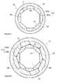
- FIG. 2is an axial cross-sectional view of the delivery member used in the medical device of FIG. 1 according to one aspect of the present invention
- FIG. 3is a geometric representation of the cross-sectional area of the delivery member used in the medical device of FIG. 1 according to one aspect of the present invention
- FIG. 4is an axial cross-sectional view of the delivery member of the medical device of FIG. 1 according to another aspect of the present invention.
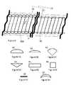
- FIG. 5Ais a cross-sectional view of a wire strand having a half-round shape according to one aspect of the present invention.
- FIG. 5Bis a cross-sectional view of a wire strand having less than half-round shape according to another aspect of the present invention.
- FIG. 5Cis a cross-sectional view of a wire strand having pie shape according to another aspect of the present invention.
- FIG. 5Dis a cross-sectional view of a wire strand having a triangular shape according to another aspect of the present invention.
- FIG. 5Eis a cross-sectional view of a wire strand having a rectangular shape according to another aspect of the present invention.
- FIG. 5Fis a cross-sectional view of a wire strand having a square shape according to another aspect of the present invention.
- FIG. 5Gis a cross-sectional view of a wire strand having flat shape according to another aspect of the present invention.
- FIG. 5His a cross-sectional view of a wire strand having half moon shape according to another aspect of the present invention.
- FIG. 6is a longitudinal cross-sectional view of the delivery member of the medical device of FIG. 1 according to yet another aspect of the present invention.
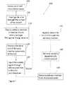
- FIG. 7is a schematical representation of a method for using the medical device of FIG. 1 for the removal of emboli according to the teachings of the present invention.
- a medical device 10 for intracranial clot removalhaving a distal end 30 , an elongated tubular delivery member 15 extending from the distal end 30 to a proximal end 35 .
- the delivery member 15has both a proximal portion 20 and a distal portion 25 with the proximal portion 20 being in contact with a leak-free connector 40 that is compatible for use with fibrinolytic infusion, vacuum retrieval methodology, or both.
- the proximal portion 20 and the distal portion 25 of the delivery member 15may be different in their predetermined degree of rigidity.
- the delivery member 15is comprised of a metal core 52 of helically wound multiple wire strands 50 A.
- Each wire strand 50 Ahas an A-side 47 and a B-side 48 with the A-side 47 of the combined strands 50 A forming a central longitudinally extending lumen 45 .
- Each of the metal strandshas a width and thickness defined as W 1 and T, respectively.
- a polymer overlay 55is disposed about the metal core 52 or about the B-side 48 of the wire strands 50 A.
- the helically wound wire strands 50 Ageometrically form a first polygon defined by the B-side 48 of the strands 50 A and a second polygon defined by the A-side 47 of the strands 50 A.
- the geometry associated with the metal core 52is further described.
- the B-side 48 and the A-side 47 of the helically wound wire strands 50 Aform a first polygon 70 and a second polygon 75 , respectively, with the second polygon defining the shape of the lumen 45 of the metal core 52 .
- the polygonal shape of the lumen 45is preferable in order to maintain a wide open working channel or lumen through which a fibrinolytic agent may be delivered to a clot or thrombus. This wide open channel or lumen allows for the fibrinolytic agent to be effectively delivered in the shortest amount of time.
- the first polygon 70can be shown to inscribe a first circle 80 , while the second polygon 75 is shown to circumscribe a second circle 85 , respectively.
- the first circle 80may further be defined as having a radius, R 1 .
- the inscribed first polygon 70may be defined by N-sides (S 1 ) with the length of each side being further described by the relationship shown in Equation 1 .
- the second circle 85may further be defined as having a radius, R 2 .
- the circumscribed second polygon 75may be defined by N-sides (S 2 ) with the length of each side being further described by the relationship provided in Equation 2.
- Nrepresents the number of wire strands 50 A used to form the wire core 52 .
- R 1 and R 2are due to the thickness (T) associated with the wire strands 50 A.
- Tthickness associated with the wire strands 50 A.
- the cross-sectional area (A 1 ) of the first polygon 70can be described by the relationship depicted in Equation 3.
- the cross-sectional area (A 2 ) of the second polygon 75can be described by the relationship shown in Equation 4.
- the polygonal shape of the metal core 52provides for a cross-sectional area (A 2 ) of the lumen 45 formed therein to be greater than the circular cross-sectional area of a lumen formed by conventional helical wire winding that has a radius equivalent to R 1 .
- a 1 /A 2⁇ [( R 1 ) 2 ⁇ cos 2 ( ⁇ / N )]/( R 2 ) 2 Eq. 5
- the delivery member 15may further comprise a second layer of helically wound multiple wire strands 50 B where the A-side 51 of the wire strands 50 B of this second layer are disposed about the B-side 48 of the first layer of helically wound wire strands 50 A.
- this second layer of wire strands 50 Bis similar to the first layer of wire strands 50 A in the number of strands, it differs in that the width (W 2 ) of each strand in the second layer is larger than the width (W 1 ) of each strand in the first layer.
- the use of a second layer of wire strands 50 Bcan enhance the impermeability of the delivery member 15 , it also may reduce the flexibility of the delivery member 15 .
- the polymer overlayis disposed about the B-side 53 of the wire strands 50 B.
- the delivery member 15 of the medical device 10may be a catheter that is normally open ended at both the proximal 35 and the distal end 30 .
- a cathetercan be used for the intracranial removal of a clot after subjecting said clot to fibrinolytic infusion and/or assisting the removal of the clot through the application of a vacuum.
- the medical device 10 of the present inventionmay be useful in a variety of other applications, including but not limited to percutaneous transluminal coronary angioplasty, drug delivery, and as a guiding catheter.
- the wire strands 50 A that are helically wound into the metal core 52may be comprised of any linear elastic material, including but not limited to stainless steel platinum alloys, titanium, tantalum, or a superelastic alloy, such as nitinol.
- the wire strands 50 Ahave a tensile strength in the range of 1800 to 2700 N/mm 2 but lower or higher values are also possible.
- the metal core 52 of the delivery member 15may be made by winding the metal strands 50 A according to any method known to one skilled-in-the-art. For example, a group of about five to twelve wire strands 50 A having the desired wire diameter may be placed in a row next to or closely adjacent to each other.
- the wire strands 50 Aare then wound according to the desired pitch angle into an elongated, tubular metal core 52 . Because a row of wires is wound, each individual wire strand 50 A is restricted in movement by the other wire strands 50 A and is plastically deformed into a permanent helical shape which is kept without any further restraints other than each wire assists in keeping the other wires aligned in the row.
- the helical winding of the strands 50 Aforms a lumen 45 defined by the A-side 47 of the strands 50 A.
- the coiled wire strands 50 Acan be subjected to heat treatment or drawing in order to further define the tubular structure and to reduce the presence of any residual stresses.
- heat treatmentmay be performed over a period of about two to twenty hours at a temperature between about 400 to 600° C.
- the wire strands 50 A in the resulting helically wound metal core 52will maintain their position even when heavy torque is applied and the metal core 52 is bent or pushed in a specific direction. Such resiliency results presumably because each single wire strand 50 A is supported by the other contiguous wire strands 50 A in the wound metal core 52 .
- the size of the pitch angle ( ⁇ ) as defined in FIG. 6depends on the width of the wire strands 50 A, the diameter of the desired lumen 45 and the number of wire strands 50 A used to form the metal core 52 .
- the most preferred pitch angle for a catheteris in the range of 40° to 70° with the specific angle being determined by the desired balance in the metal core 52 between torque transferability and transverse flexibility.
- the width (w 1 ) of the individual wire strands 50 Ais typically in the range of about 0.10 to 1.25 mm, and preferably in the range of 0.15 to 0.50 mm.
- the present inventionincludes providing a medical device having different segments wherein the row of wires is set to different pitch angles, or wherein different rows of wires have different pitch angles.
- each wire strand 50is a type of shaped wire with the shape being selected as one from the group of half round shaped D-wire 60 , less than half round shaped D-wire 61 , pie angle shaped wire 62 with greater than about a 90° degree angle, triangular shaped wire 63 having an obtuse angle, rectangular shaped wire 64 , square shaped wire 65 , flat shaped wire 66 , crescent shaped wire 67 , and combinations thereof.
- the shaped wireis one selected from the group of half-round 60 shaped wire, less than half-round 61 shaped wire, triangular 63 shaped wire, rectangular 64 shaped wire, and combinations thereof.
- a polymer overlay 55is disposed about the wound wire strands 50 A that form the metal core 52 .
- the polymer overlay 55is provided on to the B-side 48 , 53 of the wire strands 50 A, 50 B or the external surface of the metal core 52 .
- the polymer overlay 55may be a material coated onto the outer surface of the core 52 , a material extruded around the core 52 , or a shrink tubing material that is pushed over the core 52 .
- the polymer overlay 55is preferably a thin layer of an elastic material that extends along the entire length of the delivery member 15 .
- the polymer overlay 55will reduce the tendency of the delivery member 15 to stick to the vascular wall.
- the polymer overlay 55is typically applied after the winding and heat treatment of the metal core 52 has been completed.
- the polymer overlay 55may be a PTFE coating applied onto the external surface of the metal core 52 in the same manner as such a coating is traditionally applied onto the exterior of a guide wire.
- the polymer overlay 55 as disposed about the metal core 52i.e., on the B-side 48 of the metal strands 50 A, results in less than about a 5 to 15% increase in the outer diameter of the delivery member 15 .
- the composition of the polymer overlay 55may include, but not be limited to, fluoropolymers, hyrdrophilic elastomers, polyolefins, and combinations or mixtures thereof.
- fluoropolymersinclude ethylene-tetrafluoroethylene (ETFE), perfluroralkoxyethylene-tetrafluoroethylene (PFA), fluorinated ethylene propylene (FEP), copolymers of tetrafluoroethylene (TFE) and polytetrafluoroethylene (PTFE).
- hydrophilic coatingsinclude crosslinked polyacrylates, copolymers of acrylic acid, polymethacrylate, polyacrylamides, poly(vinyl alcohol), poly(ethylene oxide), poly(ethylene imine), carboxymethylcellulose, methylcellulose, poly(acrylamide sulphonic acid), polyacrylonitrile, and poly(vinyl pyrrolidone).
- polyolefinsinclude polyethylene and polypropylene.
- biomedical polymersexist that are suitable for use as a polymer overlay 55 .
- the hardness of the polymer overlay 55 disposed about the metal core 52can affect the flexibility associated with the delivery member 15 .
- Hardnessis one of the more important physiomechanical characteristics of a material that influences the ability of the material to resist elastic and plastic deformation of the material's surface. The term adequately applies to the resistance of a material against deformation that arises from indentation, scratching, cutting, or bending phenomena.
- the application of a load that induces a shear strain in a materialcan cause the various structural elements of the material to become displaced relative to one another. The degree or magnitude of this displacement depends upon the hardness exhibited by the material and the magnitude of the applied load.
- the hardness exhibited by a materialis a composite of multiple contributing factors, such as yield strength, work hardening, tensile stress, and modulus, rather than a basic property of the material itself.
- Hardnesscan be readily measured using a variety of standard test methods known to one skilled-in-the-art, including but not limited to Shore, Brinell, Vickers, and Rockwell testing.
- the hardness of the polymer overlay 55can be predetermined and varied by modifying the contributing factors described above or through the incorporation of various types and amounts of inert filler materials, such as glass, silicon dioxide, and aluminum oxide, into the polymer overlay 55 .
- the delivery member 15can be made with a uniform diameter (d) throughout its elongated traverse length.
- the distal portion 25as a whole or in specific locations may exhibit a diminishing wall thickness (T) associated with the wire strands 50 A in the metal core 52 .
- Such a distal portion 25may be fabricated by machining or grinding a region of the wire strands 50 A to a desired thickness dimension after they are helically wound into the metal core 52 .
- This machined regioncan extend along the entire length of the delivery member 15 , so that the delivery member 15 may exhibit a very precise outer dimension overall.
- the machined regionis part of the distal portion 25 of the delivery member 15 .
- the machined regionmay be tapered, i.e., diameter decreases, which allows the device to exhibit increasing flexibility as one moves towards the distal end 30 of the delivery member 15 .
- This increased level of flexibility in the distal portion 25 of the delivery member 15facilitates the introduction of the delivery member 15 into very diminutive vessels.
- the reduced cross-sectional area of the wire strands 50 A produced by the machining operationgreatly increases the bending flexibility of the medical device 10 without sacrificing its ability to transfer torque.
- the delivery member 15may be composed of several segments in which the wires have mutually different thicknesses (T). However, the cross-sectional area of the lumen is maintained substantially similar between the different segments in order to prevent the occurrence of any obstruction to the advancement of a guide wire or other device through the lumen.
- the different segmentsmay be joined together in axial extension by laser welding, soldering, bracing, or any other method known to one skilled-in-the-art.
- the distal portion 25 of the delivery member 15may also be tapered towards its distal end 30 in order to enhance an interaction with a guide wire.
- the tapercan either be restricted to the distal end 30 or extend along any desired length of the distal portion 25 of the delivery member 15 . Due to this taper, the distal portion 25 will benefit from gradually increasing transverse flexibility and a higher degree of softness.
- the distal end 30may optionally include some type of radiopaque material, such as gold, platinum, iridium, palladium, or rhodium, or a mixture thereof.
- the radiopaque materialcan be of annular shape located at a predetermined distance from the distal end or the distal end 30 of the delivery member 15 can be provided with a marker means for making it radiopaque, such as a gold layer or a gold thread.
- the leak-free connector 40may be selected as any vacuum fitting or fluid fitting known to one skilled-in-the-art.
- the leak-free connector 40is a Luer-taper fitting, such as a Luer-Lok or Luer-Slip fitting.
- a Luer-Lok fittingutilizes a tabbed hub on the female portion of the fitting to engage threads positioned on the sleeve of the mating male portion of the fitting in order to achieve leak-free behavior.
- a Luer-Slip fittingtypically utilizes frictional forces to maintain connectivity throughout the tapered fitting.
- the metal core 52By making the metal core 52 from a group of at least five wire strands 50 A that are helically wound with a pitch angle roughly corresponding to the aggregate width of the adjacent strands 50 A, the strands 50 A transfer torque and also force components directed in the axial direction of the delivery member 15 , i.e., from the proximal end 35 to its distal end 30 .
- the delivery member 15exhibits a very high resistance to kinking and less concentration of transmitted forces in areas where the delivery member bends due to the influence of the vascular walls.
- the medical device 10can be used with very small and distant vessels, such as deep brain sites accessed by intracranial catheterization.
- the delivery member 15 of the present inventionexhibits a more pronounced ability to transfer torque, low windup, whip, pushability, and use tension as other commonly used unifilar or multifilar coiled cannulas without sacrificing compression strength, hoop strength, or thin wall thickness.
- the group or row of wiresis made up of from about 5 to 12 helically wound wires, preferably from 6 to 9 helically wound wires. Since several wires are used, their aggregate width can be adapted to correspond to the desired pitch for the given diameter of the device. A row of more than 12 wires would have a tendency to buckle when the wires are helically wound in a conventional winding operation.
- the wire strands 50 A when positioned in a roware preferably located closely next to each other so that they can mutually contact and support each other. Any possible deflection of a single wire strand 50 A is therefore reduced to a minimum by the others strands 50 A located in the row.
- the inside surface of the metal core 52 of the present inventionis found to be consistent, thereby, promoting the axial advancement of a guide wire or other device through the delivery member 15 .
- the wire strands 50 Ahave a pitch angle in the range of about 25° to 77°, preferably a pitch angle in the range of 40° to 65°.
- angles chosen in these rangesprovide a balanced solution to the requirements for desired high flexibility, high column strength, and fine torqueability.
- the preferred range of 40° to 65°is useful for advancing a catheter through small sized vessels, such as in blood vessels in the brain.
- a pitch angle in the range of about 35° to 40°is useful when a very high degree of flexibility is required.
- a pitch angle in the range of about 70° to 75°is useful when the application calls for a very high amount of pushability.
- One skilled-in-the-artwill realize that it is possible to choose different pitch angles in different segments of the delivery member 15 .
- the wire strands 50 Aare to a large extent mutually locked in position because the strands 50 A are wound and drawn together. Thus one wire strand 50 A is kept in place by the other strands 50 A. However, some mutual movement can occur between the wire strands 50 A.
- the polymer overlay 55is useful in sealing any interstice that may exist between the wire strands 50 A, thereby, rendering the delivery member 15 leak-proof.
- the elasticity of the polymer overlay 55allows small mutual movements of the wire strands 50 A to occur, thereby, imparting excellent flexibility to the helically wound metal core 52 .
- the distal portion 25 of the delivery member 15be at least 30 cm in length with the maximum outer diameter of said distal portion being less than 2.0 mm.
- the maximum outer diameter of the delivery member 15has a profound effect on suitable application of the medical device 10 .
- An outer diameter of less than about 1.00 mmallows the introduction of the delivery member 15 into fine, diminutive vessels, such as the external and internal carotid arteries.
- An outer diameter less than about 0.75 mmallows an operator to advance the delivery member into the liver and other soft tissue areas.
- An outer diameter less than about 0.30 mm in at least the last 10 cm length of the distal portion 25 before the distal end 30makes distant vascular regions accessible allowing the delivery member 15 to be used as a neuro-microcatheter.
- the polymer overlay 55can be deposit as a multilayer coating, e.g., a coating comprising a primer-coating and a top-coat where the primer-coating is chosen to provide strong bonding to the wire strands 50 A, and the top-coat providing the sealing and acting as a hydrophilic, low friction surface.
- a multilayer coatinge.g., a coating comprising a primer-coating and a top-coat where the primer-coating is chosen to provide strong bonding to the wire strands 50 A, and the top-coat providing the sealing and acting as a hydrophilic, low friction surface.
- Another objective of the present inventionis to provide a method for performing fibrinolysis by chemical infusion and/or the vacuum removal of emboli present in a vasculature of a patient.
- FIG. 7a method of addressing fibrin clots formed in a small vessel, such as an intracranial vasculature, is shown according to the teachings of the present invention.
- This methodcomprises the steps of introducing a sheath having a lumen into a blood vessel; inserting a guide wire through the lumen of the sheath; deploying the elongated tubular delivery member of a medical device having distal and proximal portions with a common lumen over the guide wire into the blood vessel; positioning the distal end of the delivery member proximate to a clot; removing the guide wire; injecting a fibrinolytic agent into the blood vessel through the delivery member until the clot is dissolved; and removing the delivery member of the medical device from the blood vessel.
- the delivery member 15 of the medical device 10has a metal core 52 comprising multiple shaped-wire strands 50 A having an A-side 47 and a B-side 48 , the wire strands 50 A helically wound to form a lumen 45 with its inner diameter being defined by the A-side 47 of the strands and a polymer overlay 55 disposed about the B-side 48 of the metal core 52 ; said helically wound wire strands 50 A further forming a first polygon 70 defined by the B-side 48 of the strands and a second polygon 75 defined by the A-side 47 of the strands 50 A; the second polygon 75 defining the shape of the lumen 45 .
- the medical device 10further comprising a connector 40 engaged with the proximal portion of the delivery member 15 .
- the connector 40being compatible for use with fibrinolytic agents, application of a vacuum, or both.
- the step of positioning the delivery member proximate to the clotcan be accomplished due to the rigidity of the proximal portion being greater than the rigidity of the distal portion.
- the step of injecting a fibrinolytic agent into the blood vessel through the delivery member until the clot is dissolvedis facilitated by the metal core having an inside diameter that is less than about 1.25 mm and an outside diameter that is greater than about 0.30 mm; with the ratio of the inside diameter to the outside diameter being greater than about 1.5.
- the method 100may further comprise the steps of applying a vacuum to through the delivery member to a clot that is only partially dissolved and removing the partially dissolved clot via the vacuum.
Landscapes
- Health & Medical Sciences (AREA)
- Life Sciences & Earth Sciences (AREA)
- Animal Behavior & Ethology (AREA)
- Veterinary Medicine (AREA)
- Public Health (AREA)
- Engineering & Computer Science (AREA)
- Biomedical Technology (AREA)
- Heart & Thoracic Surgery (AREA)
- General Health & Medical Sciences (AREA)
- Anesthesiology (AREA)
- Hematology (AREA)
- Pulmonology (AREA)
- Biophysics (AREA)
- Surgery (AREA)
- Orthopedic Medicine & Surgery (AREA)
- Vascular Medicine (AREA)
- Nuclear Medicine, Radiotherapy & Molecular Imaging (AREA)
- Medical Informatics (AREA)
- Molecular Biology (AREA)
- Media Introduction/Drainage Providing Device (AREA)
- Surgical Instruments (AREA)
Abstract
Description
S1≈2·(R1)·sin(π/N) Eq. 1
S2≈2·(R2)·tan(π/N) Eq. 2
A1≈[N·(S1)2]/[4·tan(π/N)] Eq. 3
A2≈[N·(S2)2]/[4·tan(π/N)] Eq. 4
A1/A2≈[(R1)2·cos2(π/N)]/(R2)2 Eq. 5
Claims (20)
[(R1)2·cos2(π/N)]/(R2)2,
Priority Applications (2)
| Application Number | Priority Date | Filing Date | Title |
|---|---|---|---|
| US12/535,229US8100881B2 (en) | 2009-08-04 | 2009-08-04 | Flexible medical device for clot removal from small vessels |
| PCT/US2010/044398WO2011017423A1 (en) | 2009-08-04 | 2010-08-04 | Flexible medical device for clot removal from small vessels |
Applications Claiming Priority (1)
| Application Number | Priority Date | Filing Date | Title |
|---|---|---|---|
| US12/535,229US8100881B2 (en) | 2009-08-04 | 2009-08-04 | Flexible medical device for clot removal from small vessels |
Publications (2)
| Publication Number | Publication Date |
|---|---|
| US20110034863A1 US20110034863A1 (en) | 2011-02-10 |
| US8100881B2true US8100881B2 (en) | 2012-01-24 |
Family
ID=42983373
Family Applications (1)
| Application Number | Title | Priority Date | Filing Date |
|---|---|---|---|
| US12/535,229Active2029-12-03US8100881B2 (en) | 2009-08-04 | 2009-08-04 | Flexible medical device for clot removal from small vessels |
Country Status (2)
| Country | Link |
|---|---|
| US (1) | US8100881B2 (en) |
| WO (1) | WO2011017423A1 (en) |
Cited By (16)
| Publication number | Priority date | Publication date | Assignee | Title |
|---|---|---|---|---|
| US20130317476A1 (en)* | 2012-05-23 | 2013-11-28 | Gary Searle | Collapse-resistant swellable catheter |
| US9039637B2 (en) | 2013-03-13 | 2015-05-26 | Cook Medical Technologies Llc | Flexible cytology coil |
| US9095330B2 (en) | 2013-03-13 | 2015-08-04 | Cook Medical Technologies Llc | Perforated tube for cell collection |
| US9119609B2 (en) | 2013-03-13 | 2015-09-01 | Cook Medical Technologies Llc | Rotating cell collection device |
| US9320502B2 (en) | 2013-03-12 | 2016-04-26 | Cook Medical Technologies Llc | Cytology balloon |
| US9332998B2 (en) | 2012-08-13 | 2016-05-10 | Covidien Lp | Apparatus and methods for clot disruption and evacuation |
| US9332999B2 (en) | 2012-08-13 | 2016-05-10 | Covidien Lp | Apparatus and methods for clot disruption and evacuation |
| US9427550B2 (en) | 2012-11-09 | 2016-08-30 | St. Jude Medical, Cardiology Division, Inc. | Devices and methods for delivering vascular implants |
| US20170095641A1 (en)* | 2015-10-06 | 2017-04-06 | Covidien Lp | Catheter with curvilinear polygon cross-sectional shape |
| US9737672B2 (en) | 2007-08-07 | 2017-08-22 | Belmont Instrument Corporation | Hyperthermia, system, method, and components |
| US10137257B2 (en) | 2016-11-30 | 2018-11-27 | Belmont Instrument, Llc | Slack-time heating system for blood and fluid warming |
| US10485936B2 (en) | 2016-11-30 | 2019-11-26 | Belmont Instrument, Llc | Rapid infuser with advantageous flow path for blood and fluid warming |
| US10507292B2 (en) | 2016-11-30 | 2019-12-17 | Belmont Instrument, Llc | Rapid infuser with vacuum release valve |
| US11000407B2 (en) | 2007-08-07 | 2021-05-11 | Belmont Instrument, Llc | Hyperthermia, system, method, and components |
| US11123484B2 (en) | 2005-09-02 | 2021-09-21 | Belmont Instrument, Llc | Pressure responsive fluid flow control valves |
| US12397129B2 (en) | 2015-07-30 | 2025-08-26 | Normedix, Inc. | Coronary guide catheter |
Families Citing this family (15)
| Publication number | Priority date | Publication date | Assignee | Title |
|---|---|---|---|---|
| US10207069B2 (en) | 2008-03-31 | 2019-02-19 | Covidien Lp | System and method for determining ventilator leakage during stable periods within a breath |
| US8267085B2 (en)* | 2009-03-20 | 2012-09-18 | Nellcor Puritan Bennett Llc | Leak-compensated proportional assist ventilation |
| US8272380B2 (en)* | 2008-03-31 | 2012-09-25 | Nellcor Puritan Bennett, Llc | Leak-compensated pressure triggering in medical ventilators |
| US8746248B2 (en)* | 2008-03-31 | 2014-06-10 | Covidien Lp | Determination of patient circuit disconnect in leak-compensated ventilatory support |
| US20100071696A1 (en)* | 2008-09-25 | 2010-03-25 | Nellcor Puritan Bennett Llc | Model-predictive online identification of patient respiratory effort dynamics in medical ventilators |
| US8250844B2 (en)* | 2008-10-09 | 2012-08-28 | W. C. Heraeus Gmbh | Helically-wound cable and method |
| US8117817B2 (en)* | 2008-10-09 | 2012-02-21 | W. C. Heraeus Gmbh | Helically-wound cable and method |
| US8424521B2 (en)* | 2009-02-27 | 2013-04-23 | Covidien Lp | Leak-compensated respiratory mechanics estimation in medical ventilators |
| US8418691B2 (en)* | 2009-03-20 | 2013-04-16 | Covidien Lp | Leak-compensated pressure regulated volume control ventilation |
| IL215655B (en) | 2011-10-10 | 2018-05-31 | Amnis Therapeutics Ltd | System for retrieving and anchoring a corpus |
| KR20140098794A (en)* | 2011-11-23 | 2014-08-08 | 마이크로벤션, 인코포레이티드 | Embolic device with shaped wire |
| US9498589B2 (en) | 2011-12-31 | 2016-11-22 | Covidien Lp | Methods and systems for adaptive base flow and leak compensation |
| JP2013158588A (en)* | 2012-02-08 | 2013-08-19 | Sumitomo Bakelite Co Ltd | Medical coil, medical device and method for producing medical coil |
| US9675771B2 (en) | 2013-10-18 | 2017-06-13 | Covidien Lp | Methods and systems for leak estimation |
| EP2893950A1 (en)* | 2014-01-14 | 2015-07-15 | Alvimedica Vascular Research B.V. | Catheter and method for manufacturing such catheter |
Citations (33)
| Publication number | Priority date | Publication date | Assignee | Title |
|---|---|---|---|---|
| US4932419A (en) | 1988-03-21 | 1990-06-12 | Boston Scientific Corporation | Multi-filar, cross-wound coil for medical devices |
| US5290230A (en) | 1992-05-11 | 1994-03-01 | Advanced Cardiovascular Systems, Inc. | Intraluminal catheter with a composite shaft |
| US5601539A (en) | 1993-11-03 | 1997-02-11 | Cordis Corporation | Microbore catheter having kink-resistant metallic tubing |
| EP0806596A1 (en) | 1996-04-30 | 1997-11-12 | Target Therapeutics, Inc. | Super-elastic alloy braid structure |
| US5769830A (en) | 1991-06-28 | 1998-06-23 | Cook Incorporated | Soft tip guiding catheter |
| US5891090A (en) | 1994-03-14 | 1999-04-06 | Advanced Cardiovascular Systems, Inc. | Perfusion dilatation catheter with expanded support coil |
| US6193686B1 (en) | 1999-06-30 | 2001-02-27 | Advanced Cardiovascular Systems, Inc. | Catheter with enhanced flexibility |
| US20010016728A1 (en) | 1996-10-21 | 2001-08-23 | Gregory Kelley | Flexiable and reinforced tubing |
| US6306124B1 (en) | 1995-11-13 | 2001-10-23 | Micro Therapeutics, Inc. | Microcatheter |
| US20020139785A1 (en) | 1994-03-14 | 2002-10-03 | Peacock James C. | Catheter providing intraluminal access |
| US20020198492A1 (en) | 2001-06-26 | 2002-12-26 | John Miller | Balloon catheter |
| US6524300B2 (en) | 2000-01-03 | 2003-02-25 | Angiodynamics, Inc. | Infusion catheter with non-uniform drug delivery density |
| US6530935B2 (en) | 1996-02-02 | 2003-03-11 | Regents Of The University Of California, The | Clot capture coil and method of using the same |
| US6589227B2 (en) | 2000-01-28 | 2003-07-08 | William Cook Europe Aps | Endovascular medical device with plurality of wires |
| US20040087968A1 (en) | 2002-10-25 | 2004-05-06 | Nmt Medical, Inc. | Expandable sheath tubing |
| US20040153110A1 (en) | 1999-05-17 | 2004-08-05 | Kurz Daniel R. | Clot retrieval device |
| US20040181207A1 (en) | 2003-03-12 | 2004-09-16 | Vitullo Jeffrey M. | Catheter with limited longitudinal extension |
| US6818001B2 (en) | 2000-04-05 | 2004-11-16 | Pathway Medical Technologies, Inc. | Intralumenal material removal systems and methods |
| US6881194B2 (en) | 2001-03-21 | 2005-04-19 | Asahi Intec Co., Ltd. | Wire-stranded medical hollow tube, and a medical guide wire |
| WO2006020044A1 (en) | 2004-07-21 | 2006-02-23 | Cook Incorporated | Introducer sheath and method for making |
| US7020947B2 (en) | 2003-09-23 | 2006-04-04 | Fort Wayne Metals Research Products Corporation | Metal wire with filaments for biomedical applications |
| US20060095018A1 (en) | 2004-10-28 | 2006-05-04 | Pursley Matt D | Catheter with curved distal end and method of making the same |
| US20060100602A1 (en) | 2001-01-26 | 2006-05-11 | William Cook Europe Aps | Endovascular medical device with plurality of wires |
| US20060111649A1 (en)* | 2004-11-19 | 2006-05-25 | Scimed Life Systems, Inc. | Catheter having improved torque response and curve retention |
| US7100891B2 (en) | 2001-08-10 | 2006-09-05 | Cardinal Health 303, Inc. | Valved male luer with vacuum feature |
| US20060200074A1 (en) | 1996-05-20 | 2006-09-07 | Gholam-Reza Zadno-Azizi | Method and apparatus for emboli containment |
| US7117703B2 (en) | 2002-12-11 | 2006-10-10 | Asahi Intecc Co., Ltd. | Wire-stranded hollow coil body, a medical equipment made therefrom and a method of making the same |
| US20070016233A1 (en) | 1997-12-05 | 2007-01-18 | Ferrera David A | Vasoocclusive device for treatment of aneurysms |
| US7182757B2 (en) | 2003-12-25 | 2007-02-27 | Asahi Intecc Co., Ltd. | Medical guide wire |
| US20080045881A1 (en) | 2004-03-26 | 2008-02-21 | University Of Southern California | Devices and methods for removing a matter from a body cavity of a patient |
| US20080065045A1 (en) | 2002-07-23 | 2008-03-13 | Von Hoffmann Gerard | Intracranial aspiration catheter |
| US20090054826A1 (en) | 2007-08-21 | 2009-02-26 | Cook Critical Care Incorporated | Multi-lumen catheter |
| US7501579B2 (en) | 2004-02-11 | 2009-03-10 | Fort Wayne Metals Research Products Corporation | Drawn strand filled tubing wire |
- 2009
- 2009-08-04USUS12/535,229patent/US8100881B2/enactiveActive
- 2010
- 2010-08-04WOPCT/US2010/044398patent/WO2011017423A1/enactiveApplication Filing
Patent Citations (34)
| Publication number | Priority date | Publication date | Assignee | Title |
|---|---|---|---|---|
| US4932419A (en) | 1988-03-21 | 1990-06-12 | Boston Scientific Corporation | Multi-filar, cross-wound coil for medical devices |
| US5769830A (en) | 1991-06-28 | 1998-06-23 | Cook Incorporated | Soft tip guiding catheter |
| US5290230A (en) | 1992-05-11 | 1994-03-01 | Advanced Cardiovascular Systems, Inc. | Intraluminal catheter with a composite shaft |
| US5601539A (en) | 1993-11-03 | 1997-02-11 | Cordis Corporation | Microbore catheter having kink-resistant metallic tubing |
| US5891090A (en) | 1994-03-14 | 1999-04-06 | Advanced Cardiovascular Systems, Inc. | Perfusion dilatation catheter with expanded support coil |
| US20020139785A1 (en) | 1994-03-14 | 2002-10-03 | Peacock James C. | Catheter providing intraluminal access |
| US6306124B1 (en) | 1995-11-13 | 2001-10-23 | Micro Therapeutics, Inc. | Microcatheter |
| US6530935B2 (en) | 1996-02-02 | 2003-03-11 | Regents Of The University Of California, The | Clot capture coil and method of using the same |
| EP0806596A1 (en) | 1996-04-30 | 1997-11-12 | Target Therapeutics, Inc. | Super-elastic alloy braid structure |
| US20060200074A1 (en) | 1996-05-20 | 2006-09-07 | Gholam-Reza Zadno-Azizi | Method and apparatus for emboli containment |
| US20010016728A1 (en) | 1996-10-21 | 2001-08-23 | Gregory Kelley | Flexiable and reinforced tubing |
| US20070016233A1 (en) | 1997-12-05 | 2007-01-18 | Ferrera David A | Vasoocclusive device for treatment of aneurysms |
| US20040153110A1 (en) | 1999-05-17 | 2004-08-05 | Kurz Daniel R. | Clot retrieval device |
| US6193686B1 (en) | 1999-06-30 | 2001-02-27 | Advanced Cardiovascular Systems, Inc. | Catheter with enhanced flexibility |
| US6524300B2 (en) | 2000-01-03 | 2003-02-25 | Angiodynamics, Inc. | Infusion catheter with non-uniform drug delivery density |
| US6589227B2 (en) | 2000-01-28 | 2003-07-08 | William Cook Europe Aps | Endovascular medical device with plurality of wires |
| US6818001B2 (en) | 2000-04-05 | 2004-11-16 | Pathway Medical Technologies, Inc. | Intralumenal material removal systems and methods |
| US20060100602A1 (en) | 2001-01-26 | 2006-05-11 | William Cook Europe Aps | Endovascular medical device with plurality of wires |
| US6881194B2 (en) | 2001-03-21 | 2005-04-19 | Asahi Intec Co., Ltd. | Wire-stranded medical hollow tube, and a medical guide wire |
| US20020198492A1 (en) | 2001-06-26 | 2002-12-26 | John Miller | Balloon catheter |
| US7100891B2 (en) | 2001-08-10 | 2006-09-05 | Cardinal Health 303, Inc. | Valved male luer with vacuum feature |
| US20080065045A1 (en) | 2002-07-23 | 2008-03-13 | Von Hoffmann Gerard | Intracranial aspiration catheter |
| US20040087968A1 (en) | 2002-10-25 | 2004-05-06 | Nmt Medical, Inc. | Expandable sheath tubing |
| US7117703B2 (en) | 2002-12-11 | 2006-10-10 | Asahi Intecc Co., Ltd. | Wire-stranded hollow coil body, a medical equipment made therefrom and a method of making the same |
| US20040181207A1 (en) | 2003-03-12 | 2004-09-16 | Vitullo Jeffrey M. | Catheter with limited longitudinal extension |
| US7020947B2 (en) | 2003-09-23 | 2006-04-04 | Fort Wayne Metals Research Products Corporation | Metal wire with filaments for biomedical applications |
| US7182757B2 (en) | 2003-12-25 | 2007-02-27 | Asahi Intecc Co., Ltd. | Medical guide wire |
| US7501579B2 (en) | 2004-02-11 | 2009-03-10 | Fort Wayne Metals Research Products Corporation | Drawn strand filled tubing wire |
| US20080045881A1 (en) | 2004-03-26 | 2008-02-21 | University Of Southern California | Devices and methods for removing a matter from a body cavity of a patient |
| WO2006020044A1 (en) | 2004-07-21 | 2006-02-23 | Cook Incorporated | Introducer sheath and method for making |
| US20060095018A1 (en) | 2004-10-28 | 2006-05-04 | Pursley Matt D | Catheter with curved distal end and method of making the same |
| WO2006055201A1 (en) | 2004-11-19 | 2006-05-26 | Boston Scientific Limited, Inc. | Catheter having improved torque response and curve retention |
| US20060111649A1 (en)* | 2004-11-19 | 2006-05-25 | Scimed Life Systems, Inc. | Catheter having improved torque response and curve retention |
| US20090054826A1 (en) | 2007-08-21 | 2009-02-26 | Cook Critical Care Incorporated | Multi-lumen catheter |
Non-Patent Citations (11)
| Title |
|---|
| A. Pusz, K. Michalik Article entitled "Examining the hardness of the high density polyethylene with method of the cone," Archives of Materials Science and Engineering, www.archivesmse.org, vol. 28, Issue 8, Aug. 200, pp. 467-470. |
| Article entitled "Biomedical Coatings," Fort Wayne Metals, www.fwmetals.com, pp. 7.1-8.1. |
| Article entitled "Helical Hollow Strand," Fort Wayne Metals, www.fwmetals.com, pp. 6.4-6.5. |
| Article entitled "Shaped Wire," Fort Wayne Metals, www.fwmetals.com, p. 6.2. |
| Article entitled "Trigonometric Formulas and Relationships," http://ca.geocities.com/xpf51/ANGLE-FORMULAS/TRIG-FORMULAS.html, 2 pages. |
| CA Jungreis, et al., Article entitled "Intracranial thrombolysis via a catheter embedded in the given clot," Journal of the American Heart Association, http://stroke.aha.journals.org, 1989, pp. 1578-1580. |
| Dan Ismailescu, Article entitled "Circumscribed Polygons of Small Area," Springer Science+Business Media, LLC, Feb. 27, 2008, 7 pages. |
| Joseph M. Eskridge, M.D., et al., Article entitled "Catheter-Related Thrombosis and Fibrinolytic Therapy," Radiology, Nov. 1983, pp. 429-432. |
| L D R Smith, et al., Article entitled "Use of a hollow wire to facilitate angioplasty of occluded vessels," Br Heart J 1989;61, pp. 326-330. |
| Muharrem Aktümen, et al., Article entitled "The Method Using Regular Polygons," The Journal of the Online Mathematics and Its Applications, http://www.maa.org/joma/Volume7/Aktumen/Polygon.html, vol. 7, 2007, 5 pages. |
| Ron Roth, Article entitled "Design Considerations in Small-Diameter Medical Tubing," Medical Device & Diagnostic Industry Magazine, www.medicaldevicelink.com, Jan. 2001, 6 pages. |
Cited By (20)
| Publication number | Priority date | Publication date | Assignee | Title |
|---|---|---|---|---|
| US11123484B2 (en) | 2005-09-02 | 2021-09-21 | Belmont Instrument, Llc | Pressure responsive fluid flow control valves |
| US9737672B2 (en) | 2007-08-07 | 2017-08-22 | Belmont Instrument Corporation | Hyperthermia, system, method, and components |
| US11000407B2 (en) | 2007-08-07 | 2021-05-11 | Belmont Instrument, Llc | Hyperthermia, system, method, and components |
| US11123520B2 (en) | 2012-05-23 | 2021-09-21 | Becton, Dickinson And Company | Collapse-resistant swellable catheter |
| US10220186B2 (en)* | 2012-05-23 | 2019-03-05 | Becton, Dickinson And Company | Collapse-resistant swellable catheter |
| US20130317476A1 (en)* | 2012-05-23 | 2013-11-28 | Gary Searle | Collapse-resistant swellable catheter |
| US9332998B2 (en) | 2012-08-13 | 2016-05-10 | Covidien Lp | Apparatus and methods for clot disruption and evacuation |
| US9332999B2 (en) | 2012-08-13 | 2016-05-10 | Covidien Lp | Apparatus and methods for clot disruption and evacuation |
| US9808266B2 (en) | 2012-08-13 | 2017-11-07 | Covidien Lp | Apparatus and methods for clot disruption and evacuation |
| US9427550B2 (en) | 2012-11-09 | 2016-08-30 | St. Jude Medical, Cardiology Division, Inc. | Devices and methods for delivering vascular implants |
| US9320502B2 (en) | 2013-03-12 | 2016-04-26 | Cook Medical Technologies Llc | Cytology balloon |
| US9095330B2 (en) | 2013-03-13 | 2015-08-04 | Cook Medical Technologies Llc | Perforated tube for cell collection |
| US9119609B2 (en) | 2013-03-13 | 2015-09-01 | Cook Medical Technologies Llc | Rotating cell collection device |
| US9039637B2 (en) | 2013-03-13 | 2015-05-26 | Cook Medical Technologies Llc | Flexible cytology coil |
| US12397129B2 (en) | 2015-07-30 | 2025-08-26 | Normedix, Inc. | Coronary guide catheter |
| US20170095641A1 (en)* | 2015-10-06 | 2017-04-06 | Covidien Lp | Catheter with curvilinear polygon cross-sectional shape |
| US10137257B2 (en) | 2016-11-30 | 2018-11-27 | Belmont Instrument, Llc | Slack-time heating system for blood and fluid warming |
| US10485936B2 (en) | 2016-11-30 | 2019-11-26 | Belmont Instrument, Llc | Rapid infuser with advantageous flow path for blood and fluid warming |
| US10507292B2 (en) | 2016-11-30 | 2019-12-17 | Belmont Instrument, Llc | Rapid infuser with vacuum release valve |
| US11872382B2 (en) | 2016-11-30 | 2024-01-16 | Belmont Instrument, Llc | Rapid infuser with advantageous flow path for blood and fluid warming, and associated components, systems, and methods |
Also Published As
| Publication number | Publication date |
|---|---|
| US20110034863A1 (en) | 2011-02-10 |
| WO2011017423A1 (en) | 2011-02-10 |
Similar Documents
| Publication | Publication Date | Title |
|---|---|---|
| US8100881B2 (en) | Flexible medical device for clot removal from small vessels | |
| US11191924B2 (en) | Catheter assembly | |
| US20220257901A1 (en) | Catheter | |
| US9144661B2 (en) | Reinforced elongate medical device and method of manufacture | |
| KR102770735B1 (en) | Integrated coil vascular device | |
| US8377035B2 (en) | Unbalanced reinforcement members for medical device | |
| US8231551B2 (en) | Elongate medical device with continuous reinforcement member | |
| US20170072165A1 (en) | Catheter shaft and associated devices, systems, and methods | |
| US20110245775A1 (en) | Tapered sheath | |
| JPH07178176A (en) | Catheter | |
| JP2008229160A (en) | Catheter | |
| EP3347078B1 (en) | Polymeric catheter shaft with reinforcement | |
| EP3347079A1 (en) | Catheter shaft and associated devices, systems, and methods | |
| US11633574B2 (en) | Guide wire | |
| JP7524080B2 (en) | Extension catheter and method for manufacturing same | |
| JP2011206174A (en) | Guide wire | |
| EP1120127B1 (en) | Catheter made of a multifilar row of wires | |
| JP3944395B2 (en) | Cerebral artery catheter and catheter device | |
| JP6372173B2 (en) | Medical equipment | |
| JP4316252B2 (en) | catheter | |
| EP1120128B1 (en) | A catheter system | |
| WO2024143282A1 (en) | Catheter | |
| JP2000140119A (en) | Catheter and catheter appliance | |
| JP2023149727A (en) | catheter assembly |
Legal Events
| Date | Code | Title | Description |
|---|---|---|---|
| AS | Assignment | Owner name:COOK INCORPORATED, INDIANA Free format text:ASSIGNMENT OF ASSIGNORS INTEREST;ASSIGNOR:HOFFA, ANDREW K.;REEL/FRAME:023049/0955 Effective date:20090729 | |
| AS | Assignment | Owner name:COOK MEDICAL TECHNOLOGIES LLC, INDIANA Free format text:ASSIGNMENT OF ASSIGNORS INTEREST;ASSIGNOR:COOK INCORPORATED;REEL/FRAME:027419/0159 Effective date:20111004 | |
| STCF | Information on status: patent grant | Free format text:PATENTED CASE | |
| FPAY | Fee payment | Year of fee payment:4 | |
| MAFP | Maintenance fee payment | Free format text:PAYMENT OF MAINTENANCE FEE, 8TH YEAR, LARGE ENTITY (ORIGINAL EVENT CODE: M1552); ENTITY STATUS OF PATENT OWNER: LARGE ENTITY Year of fee payment:8 | |
| MAFP | Maintenance fee payment | Free format text:PAYMENT OF MAINTENANCE FEE, 12TH YEAR, LARGE ENTITY (ORIGINAL EVENT CODE: M1553); ENTITY STATUS OF PATENT OWNER: LARGE ENTITY Year of fee payment:12 | |
| AS | Assignment | Owner name:WILMINGTON TRUST, NATIONAL ASSOCIATION, AS COLLATERAL AGENT, DELAWARE Free format text:SECURITY INTEREST;ASSIGNOR:COOK MEDICAL TECHNOLOGIES LLC;REEL/FRAME:066700/0277 Effective date:20240227 |