US8100869B2 - Medical valve with expandable member - Google Patents
Medical valve with expandable memberDownload PDFInfo
- Publication number
- US8100869B2 US8100869B2US11/837,417US83741707AUS8100869B2US 8100869 B2US8100869 B2US 8100869B2US 83741707 AUS83741707 AUS 83741707AUS 8100869 B2US8100869 B2US 8100869B2
- Authority
- US
- United States
- Prior art keywords
- valve
- aperture
- medical
- actuator
- resilient member
- Prior art date
- Legal status (The legal status is an assumption and is not a legal conclusion. Google has not performed a legal analysis and makes no representation as to the accuracy of the status listed.)
- Active, expires
Links
Images


Classifications
- A—HUMAN NECESSITIES
- A61—MEDICAL OR VETERINARY SCIENCE; HYGIENE
- A61M—DEVICES FOR INTRODUCING MEDIA INTO, OR ONTO, THE BODY; DEVICES FOR TRANSDUCING BODY MEDIA OR FOR TAKING MEDIA FROM THE BODY; DEVICES FOR PRODUCING OR ENDING SLEEP OR STUPOR
- A61M39/00—Tubes, tube connectors, tube couplings, valves, access sites or the like, specially adapted for medical use
- A61M39/22—Valves or arrangement of valves
- A61M39/26—Valves closing automatically on disconnecting the line and opening on reconnection thereof
- A61M2039/262—Valves closing automatically on disconnecting the line and opening on reconnection thereof having a fluid space within the valve remaining the same upon connection and disconnection, i.e. neutral-drawback valve
- A—HUMAN NECESSITIES
- A61—MEDICAL OR VETERINARY SCIENCE; HYGIENE
- A61M—DEVICES FOR INTRODUCING MEDIA INTO, OR ONTO, THE BODY; DEVICES FOR TRANSDUCING BODY MEDIA OR FOR TAKING MEDIA FROM THE BODY; DEVICES FOR PRODUCING OR ENDING SLEEP OR STUPOR
- A61M39/00—Tubes, tube connectors, tube couplings, valves, access sites or the like, specially adapted for medical use
- A61M39/22—Valves or arrangement of valves
- A61M39/26—Valves closing automatically on disconnecting the line and opening on reconnection thereof
- A61M2039/263—Valves closing automatically on disconnecting the line and opening on reconnection thereof where the fluid space within the valve is decreasing upon disconnection
- A—HUMAN NECESSITIES
- A61—MEDICAL OR VETERINARY SCIENCE; HYGIENE
- A61M—DEVICES FOR INTRODUCING MEDIA INTO, OR ONTO, THE BODY; DEVICES FOR TRANSDUCING BODY MEDIA OR FOR TAKING MEDIA FROM THE BODY; DEVICES FOR PRODUCING OR ENDING SLEEP OR STUPOR
- A61M39/00—Tubes, tube connectors, tube couplings, valves, access sites or the like, specially adapted for medical use
- A61M39/02—Access sites
- A61M39/04—Access sites having pierceable self-sealing members
- A61M39/045—Access sites having pierceable self-sealing members pre-slit to be pierced by blunt instrument
Definitions
- the inventiongenerally relates to medical valves and, more particularly, the invention relates to mitigating fluid drawback through medical valves.
- medical valving devicesoften act as a sealed port that may be repeatedly accessed to non-invasively inject fluid into (or withdraw fluid from) a patient's vasculature. Consequently, a medical valve permits the patient's vasculature to be freely accessed without requiring such patient's skin be repeatedly pierced by a needle.
- Medical personnelinsert a medical instrument into the medical valve to inject fluid into (or withdraw fluid from) a patient who has an appropriately secured medical valve. Once inserted, fluid may be freely injected into or withdrawn from the patient. Problems can arise, however, when the medical instrument is withdrawn from the valve. Specifically, suction produced by the withdrawing medical instrument can undesirably cause blood to be drawn proximally into or toward the valve. In addition to coagulating and impeding the mechanical operation of the valve, blood in the valve also compromises the sterility of the valve.
- a medical valvetransitions between an open mode that permits fluid flow, and a closed mode that prevents fluid flow.
- the medical valvehas a housing having an inlet and an outlet, an actuator, and a resilient member having an aperture that may or may not be self-sealing.
- the aperturemay be a pinhole or a slit.
- the actuatoris moveable distally within the housing after insertion of a medical implement into the inlet. Distal movement of the actuator opens the aperture, thereby transitioning the valve from the closed to the open mode. Proximal movement of the actuator can close the aperture and transition the valve from the open to the closed mode.
- the resilient membermay proximally bias the actuator.
- the actuatormay include a body portion, and a plurality of leg members extending from the body portion.
- the leg membersmay be connected to the body portion by a hinge that allows the leg members to flex or pivot with respect to the body portion.
- the moveable leg membersmay flex radially outward and apply a radial force on the aperture, causing the aperture to open.
- some or all of the leg memberscan be stationary with respect to the body portion.
- the resilient membercan include a plurality of protrusions that cooperate with the stationary leg members.
- the protrusionsmay extend proximally, and the stationary leg members may engage the protrusions as the valve transitions from the closed mode to the open mode. By engaging the protrusions, the stationary leg members prevent the aperture from closing.
- the medical valvemay include a valve seat against which the resilient member may seal.
- the valve seatmay be angled such that the resilient member deforms to the shape of the valve seat as the valve transitions from the closed to the open mode.
- the medical valvemay also have a swabbable member sealing the inlet.
- the swabbable membermay have a recloseable aperture there through.
- the housingmay also include a plurality of protrusions extending proximally from the outlet. The protrusions prevent the aperture from closing as the valve transitions from the closed mode to the open mode.
- the medical valvemay also include a plug member extending proximally, and passing through the aperture in the resilient member.
- the aperture and the plug membercooperate with one another to prevent flow through the valve in the closed mode.
- the plug membermay have a lower portion distal to the resilient member and an upper portion proximal to the resilient member.
- the lower portionmay have a plurality of channels for allowing fluid flow through the valve when in the open mode.
- the upper portion and the aperturemay have similar cross-sectional geometries (e.g., they may both be circular, oval, etc.), and the resilient member may seal against the upper portion when in the closed mode.
- the actuatormay include an actuator channel through it.
- the actuatormay have a distally extending portion
- the resilient membermay have a raised portion (e.g., a proximally extending portion) that extends into the actuator's distally extending portion.
- the distally extending portionmay provide a radially compressive force to the raised portion, and keep the aperture closed when the valve is in the closed mode.
- the valvemay produce a positive or substantially neutral fluid displacement at the outlet during disconnection of the medical implement.
- the actuator and the resilient membermay be chemically bonded to one another to form a single internal valve mechanism. Additionally or alternatively, the actuator and the resilient member may be formed using a two-shot manufacturing process, thereby creating a single internal valve mechanism.
- a methodconnects a medical valve to a patient.
- the medical valvehas a housing with an inlet and an outlet, an actuator, and a resilient member. The method then inserts a medical implement through the inlet to contact the actuator, and moves the medical implement distally within the housing to move the actuator distally. The actuator's distal movement opens an aperture within the resilient member, causing the inlet and outlet to be in fluid communication. Finally, the method transfers fluid between the medical implement and the patient through the valve.
- the valvemay form a longitudinally directed fluid channel between the inlet and the outlet when the actuator opens the aperture.
- the medical instrumentmay have a standard luer taper at its distal end. Additionally, transferring fluid can include injecting fluid from the medical implement to the patient, or removing fluid from the patient.
- FIG. 1schematically shows one use of a medical valve configured in accordance with one embodiment of the present invention.
- FIG. 2Aschematically shows a perspective view of a medical valve configured in accordance with illustrative embodiments of the present invention.
- FIG. 2Bschematically shows a perspective view of a medical valve of FIG. 2A with a Y-site branch.
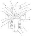
- FIG. 3schematically shows a cross-sectional view of the valve shown in FIG. 2A in the closed mode along line 3 - 3 .
- FIG. 4schematically shows a perspective exploded view of the medical valve shown in FIG. 2A .
- FIG. 5schematically shows a cross-sectional view of the valve shown in FIG. 2A in the open mode along line 3 - 3 .
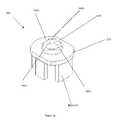
- FIG. 6schematically shows a perspective view of an illustrative embodiment of an actuator within the valve of FIG. 2A .
- FIG. 7schematically shows a perspective view of an illustrative embodiment of a resilient member within the valve of FIG. 2A .
- FIG. 8shows a process of using the medical valve shown in FIG. 2A in accordance with illustrative embodiments of the invention.
- FIG. 9Aschematically shows a cross-sectional view of an alternative embodiment having an actuator with two leg members. This figure shows the valve in the closed mode.
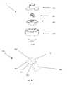
- FIG. 9Bschematically shows a perspective exploded view of the medical valve shown in FIG. 9A .
- FIG. 9Cschematically shows an illustrative embodiment of the actuator within the valve of FIG. 9A .
- FIG. 10Aschematically shows a cross-sectional view of another alternative embodiment having an outlet with proximally extending post members. This figure shows the valve in the closed mode.
- FIG. 10Bschematically shows a perspective exploded view of the medical valve shown in FIG. 10A .
- FIG. 10Cschematically shows an illustrative embodiment of the actuator within the valve of FIG. 10A .
- FIG. 10Dschematically shows an illustrative embodiment of the resilient member within the valve of FIG. 10A .
- This figureshows the resilient member as molded.
- FIG. 10Eschematically shows an illustrative embodiment of the resilient member within the valve of FIG. 10A . This figure shows the resilient member after assembly.
- FIG. 10Fschematically shows an illustrative embodiment of the outlet of the valve of FIG. 10A .
- This figureshows a section of the outlet cut-away to illustrate the proximally extending protrusion.
- FIG. 11Aschematically shows a front cross-sectional view of an alternative embodiment having two stationary and two moveable leg members. This figure shows the stationary leg members, a moveable leg member, and the valve in the closed mode.
- FIG. 11Bschematically shows a side cross-sectional view of the alternative embodiment shown in FIG. 11A . This figure shows the moveable leg members and the valve in the closed mode.
- FIG. 11Cschematically shows an illustrative embodiment of the actuator within the valve of FIG. 11A and 11B .
- FIG. 11Dschematically shows an illustrative embodiment of the resilient member within the valve of FIG. 11A and 11B .
- FIG. 11Eschematically shows a cross sectional view of the outlet of the alternative embodiment shown in 11 A
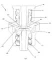
- FIG. 12Aschematically shows a front cross-sectional view an alternative embodiment having an actuator with a distally extending portion and a resilient member having a proximally extending portion. This figure shows the valve in the closed mode.
- FIG. 12Bschematically shows a perspective exploded view of the medical valve shown in FIG. 12A .
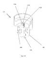
- FIG. 13Aschematically shows a front cross-sectional view an alternative embodiment having a proximally extending post member. This figure shows the valve in the closed mode.
- FIG. 13Bschematically shows a perspective exploded view of the medical valve shown in FIG. 13A .
- FIG. 13Cschematically shows an illustrative embodiment of the outlet of the valve of FIG. 13A .
- This figureshows a section of the outlet cut-away to illustrate the proximally extending post member.
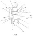
- FIG. 14schematically shows an alternative embodiment of an actuator with improved flushing.
- This alternative actuatorcan be used in conjunction with any of the above shown medical valves.
- a medical valvehas an internal valve mechanism with an actuator member that is moveable to open an aperture in a resilient member. Details of illustrative embodiments are discussed below.
- FIG. 1schematically shows one illustrative use of a medical valve 10 configured in accordance with illustrative embodiments of the invention.
- a catheter 70connects the valve 10 with a patient's vein (the patient is identified by reference number 30 ).
- Adhesive tape or similar materialmay be coupled with the catheter 70 and patient's arm to ensure that the valve remains in place.
- a nurse, doctor, technician, practitioner, or other usermay intravenously deliver medication to the patient 30 , who is lying in a hospital bed.
- the nurse 20swabs the top surface of the valve 10 to remove contaminants.
- the nurse 20uses a medical instrument (e.g., a syringe having a distally located blunt, luer tip complying with ANSI/ISO standards) to inject medication into the patient 30 through the valve 10 .
- the medical practitioner 20may use the valve 10 to inject drugs such as heparin, antibiotic, pain medication, other intravenous medication, or other fluid deemed medically appropriate.
- the nurse 20(or other user) may withdraw blood from the patient 30 through the valve 10 .
- the medical valve 10may receive medication or other fluids from other means, such as through a gravity feed system 45 .
- traditional gravity feeding systems 45often have a bag 50 (or bottle) containing a fluid (e.g., anesthesia medication) to be introduced into the patient 30 .
- the bag 50 (or bottle)typically hangs from a pole 47 to allow for gravity feeding.
- the medical practitioner 20then connects the bag/bottle 50 to the medical valve 10 using tubing 60 having an attached blunt tip.
- the blunt tip of the tubinghas a luer taper that complies with the ANSI/ISO standard.
- the feeding system 45may include additional shut-off valves on the tubing 60 (e.g., stop-cock valves or clamps) to stop fluid flow without having to disconnect the tubing 60 from the valve 10 . Accordingly, the valve 10 can be used in long-term “indwell” procedures.
- the nurse 20should appropriately swab and flush the valve 10 and catheter 70 to remove contaminants and ensure proper operation.
- valve swabbing and flushing protocolthat should mitigate the likelihood of infection.
- this protocolrequires proper flushing and swabbing before and after the valve is used to deliver fluid to, or withdraw fluid from the patient.
- FIG. 2Aschematically shows a perspective view of the medical valve 10 shown in FIG. 1
- FIG. 2Bschematically shows the same valve with a Y-site branch (discussed below).
- the valve 10may be configured to have a substantially positive fluid displacement or a substantially neutral fluid displacement (between about plus or minus 1 microliter of fluid displacement, discussed below).
- withdrawal of a medical instrument 40causes either a positive fluid displacement or essentially no or negligible fluid displacement at the distal end of the valve 10 .
- fluid displacementgenerally refers to the flow of fluid through the distal port 120 of the valve 10 (discussed below). Accordingly, a positive fluid displacement generally refers to fluid flowing in a distal direction through the distal port 120 , while a negative fluid displacement generally refers to a fluid flowing in a proximal direction through the distal port 120 .
- the valve 10may have a negative fluid displacement when the instrument 40 is withdrawn.
- the fluid displacements discussed hereinrefer to the “net” fluid displaced through the distal port 120 .
- the actual flow of fluid through the distal port 120may change direction and thus, fluctuate.
- the net change in fluid flow through the distal port 120should be 1) positive when the valve exhibits a “positive fluid displacement,” and 2) negative when the valve exhibits a “negative fluid displacement.”
- a substantially neutral fluid displacementoccurs when, as noted above, the valve 10 has a net fluid displacement of about plus or minus one microliter.
- the fluid displacement of the valve 10is discussed herein in terms of one stroke of the instrument 40 (i.e., insertion or withdrawal of the instrument 40 ).
- a valve with a neutral displacementhas 0.0 microliters of positive or negative fluid displacement.
- a neutral displacementactually can have a very slight positive or negative displacement (e.g., caused by a manufacturing tolerance), such as a displacement on the order of positive or negative one microliter, or less.
- the volumes of fluid forced through the distal port 120 in a neutral displacement valveare negligible (ideally zero microliters) and should have a negligible impact on the goals of the valve.
- Some embodimentsmay have a very low negative fluid displacement upon withdrawal.
- such valvesmay have a negative fluid displacement of about one to two microliters (i.e., about one to two microliters of fluid drawback, which is proximally directed), or about one to two microliters positive fluid displacement (i.e., about one to two microliters of positively pushed fluid, which is distally directed).
- negative fluid displacementof about one to two microliters (i.e., about one to two microliters of fluid drawback, which is proximally directed), or about one to two microliters positive fluid displacement (i.e., about one to two microliters of positively pushed fluid, which is distally directed).
- the neutral, positive, or negative fluid displacement of a valvemay be corrupted by manual handling of the valve 10 , catheter 70 or the instrument 40 during the fluid transfer.
- a slight inward force applied to the shaft of the medical instrument 40e.g., by the nurse's hand when simply holding the medical instrument 40
- the nurse 20can hold another part of the medical instrument that does not contain the fluid (e.g., stubs at the proximal end of the medical instrument 40 ).
- the valve 10has a housing 100 forming an interior having a proximal port 110 for receiving the instrument 40 , and the noted distal port 120 having the discussed fluid displacement properties.
- the valve 10has an open mode that permits fluid flow through the valve 10 , and a closed mode that prevents fluid flow through the valve 10 .
- the interiorcontains a valve mechanism that selectively controls (i.e., allow/permits) fluid flow through the valve 10 .
- the fluidpasses through a complete fluid path that extends between the proximal port 110 and the distal port 120 .
- proximal port 110as an inlet
- distal port 120as an outlet
- proximal and distal ports 110 and 120also may be respectively used as outlet and inlet ports. Discussion of these ports in either configuration therefore is for illustrative purposes only.
- the valve 10is considered to provide a low pressure seal at its proximal end 110 .
- the proximal end 110 of the medical valve 10has a resilient proximal gland 80 with a resealable aperture 130 that extends entirely through its profile.
- the aperture 130may, for example, be a pierced hole or a slit.
- the proximal gland 80may be molded with the aperture 130 .
- the aperture 130may be held closed by the inner surface of the housing 100 .
- the inner diameter of the proximal port 110is smaller than the outer diameter of the proximal gland 80 and thus, the proximal port 110 squeezes the aperture 130 closed.
- the resilient membermay be formed so that the aperture 130 normally stays closed in the absence of radially inward force provided by the inner diameter of the proximal port 110 .
- the proximal gland 80is formed so that the aperture 130 normally is closed.
- the proximal gland 80may be flush with or extend slightly above the exterior inlet face 140 of the inlet housing 160 (see FIG. 9A ).
- the proximal gland 80 and the exterior inlet face 140thus present a swabbable surface, i.e., it may be easily wiped clean with an alcohol swab, for example, or other swab.
- the proximal gland 80can be molded over the proximal port 110 (see FIG. 2A ), to provide the swabbable surface.
- Such valvestypically have been referred to in the art as “swabbable valves.”
- Various other embodiments, however,may relate to other types of valves and thus, not all embodiments are limited to swabbable valves.
- some embodimentsmay be used with instruments 40 having blunt tips that do not comply with the ANSI/ISO luer standard.
- the outside surface of the valve proximal port 110may also have inlet threads 90 for connecting the medical instrument 40 .
- the proximal endmay have a slip design for accepting instruments 40 that do not have a threaded interconnect.
- the distal end of the valve 10has a skirt 150 containing threads 280 (see FIG. 3 ) for connecting a threaded port of the catheter of FIG. 1 , or a different medical instrument, to the valve distal port 120 .
- the skirt 150may also include ribs 172 that allow the medical practitioner 20 to easily grasp and handle the valve 10 .
- the proximal end inlet threads 90 and the distal end threads 280preferably comply with ANSI/ISO standards (e.g., they are able to receive/connect to medical instruments complying with ANSI/ISO standards).
- the internal geometry of the inlet housing 160e.g., shown in FIG. 3 , discussed below
- FIG. 3schematically shows the cross section of the valve shown in FIG. 2A along the line 3 - 3 .
- the proximal seal 80is molded over the proximal port 110 .
- FIG. 3shows the valve 10 in the closed position when no medical instrument or other instrument is inserted through the proximal port 110 .
- the housing 100includes an inlet housing 160 and an outlet housing 170 , which connect together to form the interior of the medical valve 10 .
- the medical valve 10has a valve mechanism.
- the inlet housing 160 and the outlet housing 170may be joined together in a variety of ways, including a snap-fit connection, ultrasonic welding, plastic welding, or other method conventionally used in the art.
- the internal valve mechanismincludes an actuator 330 that cooperates with a resilient member 340 to selectively open and close the valve 10 .
- the actuator 330is typically formed from a relatively rigid material (e.g., plastic).
- the resilient member 340is typically formed from a resilient material that allows it to easily deform (e.g., silicone). Details of the interaction between the actuator 330 and the resilient member 340 are discussed in greater detail below, with respect to FIG. 5 .
- the actuator 330may have leg members 360 extending out from a body portion 370 .
- the leg members 360apply a force to the resilient member 340 as the actuator 330 moves distally (e.g., when a medical implement is inserted into the valve 10 ).
- the force applied to the resilient member 340causes the resilient member 340 to deform causing an aperture 350 through the resilient member 340 to open. Once the aperture 350 is open, the valve 10 is considered to be in the open mode.
- the valve 10can also include a valve seat 380 located distally from the resilient member 340 .
- the resilient member 340can seal against the valve seat to prevent leakage past the valve seat 380 and resilient member 340 and into space 382 .
- the valve seat 380can be angled (as shown in FIG. 3 ). As discussed in greater detail below, the angled valve seat 380 aids in valve 10 and aperture 350 opening because the resilient member 340 can deform to the shape of the valve seat 380 as the actuator 330 moves distally.
- FIG. 4schematically shows an exploded perspective view of the medical valve 10 shown in FIG. 3 .
- FIG. 4shows five pieces that may be assembled to form the valve 10 (i.e., the proximal gland 80 , the inlet housing 160 , the actuator 330 , the resilient member 340 , and the outlet housing 170 )
- alternative manufacturing processescan be used to reduce the total number of components.
- the proximal gland 80 and the inlet housing 160can be manufactured in a “two-shot” or “over-mold” process.
- the two-shot manufacturing processcreates one piece formed with two materials (i.e., the elastomeric proximal gland 80 material and the material forming the rigid inlet housing 160 ) that are chemically bonded to one another.
- the resilient member 340 and the outlet housing 170can be manufactured in a two-shot process to form a one-piece bottom housing.
- the actuator 330 and the resilient member 340can be manufactured in a two-shot process to form a single internal valve mechanism. Therefore, the “two-shot” manufacturing process can reduce the total number of valve components to as few as three, significantly reducing assembly complexity.
- use of a two-shot processcan significantly minimize the possibility of fluid leaking between the proximal gland 80 and inlet housing 160 .
- use of a two shot processcan significantly minimize the possibility of fluid leaking between the resilient member 340 and the outlet housing 170 , or the resilient member 340 and the actuator 330 .
- distal movement of the actuator 330opens the valve 10 .
- the resilient member 340will begin to deform into space 382 .
- the actuator 330radially expands the resilient member 340 to open the valve 10 .
- the aperture 350 through the resilient member 340opens, fluidly communicating the proximal port 110 and the distal port 120 .
- the nurse or medical practitioner 20can then transfer fluid to or from the patient 30 .
- FIGS. 6 and 7schematically show perspective views of the actuator 330 and resilient member 340 , respectively.
- FIG. 6schematically shows additional details of the actuator 330 , which, as noted above, has a body portion 370 and a plurality of leg members 360 extending from the body portion 370 .
- the leg members 360can be connected to the body portion 370 using hinges 620 that allow the leg members 360 to flex and/or move with respect to the body portion 370 .
- the leg members 360can pivot about the body portion 370 and flex/move radially outwardly as the actuator 330 moves distally. This flexing and pivoting by the leg members 360 applies a radially outward force against the resilient member 340 and causes the aperture 350 to open.
- the leg members 360can include enlarged end portions 630 located near the bottom of the leg member 360 .
- the enlarged end portions 630can cooperate with leg recesses 710 ( FIG. 7 ) within the resilient member 340 to provide a larger surface area for the application of the radial force on the aperture 350 .
- the cooperation between the enlarged leg portions 630 and the leg recesses 710also secures the actuator 330 within the valve 10 (e.g., prevents the actuator 330 from moving or spinning within the valve 10 ).
- the actuator 330may only have two leg members 360 .
- the hinge 620allows the leg members 360 to flex/move and pivot with respect to the body portion 370 .
- the hingecan be any number of elements that allow such flexion/movement and pivoting.
- the hinge 620may simply be a thinned area between each of the leg members 360 and the body portion 370 (e.g., a living hinge).
- the hinge 620can be a separate and distinct element that connects the leg member 360 to the body portion 370 .
- the hinge 620may be an elastomeric sleeve or elastomeric portion located between each leg member 360 and the body portion 370 .
- the actuator 330has an actuator channel 610 passing through the body portion 370 .
- the actuator channel 610may be part of the fluid channel through the valve.
- FIG. 6shows an actuator channel 610 with a circular opening, any shape or size opening that allows appropriate fluid flow through the actuator 330 can be used.
- FIG. 7schematically shows more details of the resilient member 340 shown in the previous figures.
- the resilient memberhas a proximal surface 720 and an aperture surface 740 .
- the aperture surface 740may be recessed from the proximal surface 720 to create an actuator recess 730 having a vertical wall 745 between the proximal surface 720 and the aperture surface 740 .
- the resilient member 340may have leg recesses 710 located on the vertical wall 745 between the aperture surface 740 and the proximal surface 720 .
- the leg recesses 710are sized appropriately to receive the leg members 360 , and in particular, the leg ends 630 , and form a fluid tight seal between the actuator 330 and the resilient member 340 .
- the actuator 330can sit within the resilient member recess 730 , such that the leg ends 630 are within the leg recesses 710 and the top surface of the body portion 370 is substantially flush with the proximal surface 720 .
- the resilient memberhas an aperture 350 that opens as the actuator moves distally.
- the aperture 350is located on and passes through the aperture surface 740 .
- the aperture 350can be any number of elements that allow fluid to pass through the valve when the valve is in the open mode (e.g., a slit, a pinhole, a cut-out, etc.), in preferred embodiments, the aperture 350 is a slit, similar to the slit 130 passing through the proximal gland 80 .
- the slitcan be self-sealing such that it automatically closes and seals when the valve 10 is in the closed mode. In other words, no additional elements or interactions are required to close and seal the slit.
- the resilient member 340may provide a force against the actuator 330 that biases the actuator 330 proximally. Therefore, as the medical practitioner 20 begins to remove the medical instrument 40 (e.g., as the medical practitioner 20 moves the medical instrument 40 proximally), the proximal bias provided by the resilient member 340 will begin to force the actuator 330 proximally. As the actuator 330 moves proximally, the leg members 360 will begin to flex inward towards their at rest position, and the radial force on the resilient member 340 and aperture 350 will decrease. As the radial force decreases, the aperture 350 will continue to close until the aperture 350 and the valve 10 are fully closed.
- some embodimentscan exhibit a positive or substantially neutral displacement upon withdrawal of the instrument 40 .
- the volume around the actuator 330 and the resilient member 340expands as the resilient member 340 stretches and deforms.
- this volumecollapses and forces the fluid above the resilient member 340 to move distally, thereby creating a positive displacement at the distal port 120 .
- the amount that the resilient member 340 stretches and/or the length of the leg members 360may be adjusted (e.g., adjusting the amount the actuator 330 deforms the resilient member 340 ).
- the amount that the resilient member stretches and/or the length of the leg membersdecrease, the amount of fluid displacement will also decrease because the change in volume around the actuator 330 and resilient member 340 will decrease. Therefore, when the leg member length is sufficiently short and/or the amount of resilient member 340 stretching is sufficiently small, there will be only a minimal volume change around the actuator 330 and resilient member 340 , and a substantially neutral displacement at the distal port 120 .
- FIG. 8shows a process illustrating one of a plurality of illustrative uses of the medical valve 10 .
- the proximal port 110 and distal port 120 of medical valve 10should be cleaned (e.g., swabbed) prior to any connection and after any disconnection.
- a medical practitioner 20connects the medical valve 10 to the patient 30 (step 810 ). To do so, the medical practitioner 20 may connect the distal port 120 of the medical valve 10 to the catheter 70 , which terminates at a needle inserted into the patient 30 (see FIG. 1 ).
- the medical practitioner 20After connecting the valve 10 to the patient 30 , the medical practitioner 20 swabs the valve proximal port 110 and inserts the medical instrument 40 into the proximal port 110 (step 820 ). As the medical practitioner 20 moves the medical instrument distally (step 830 ) into the medical valve 10 , the tip of the instrument 40 contacts the proximal surface of the actuator 330 and begins to move the actuator 330 distally within the valve 10 . As the actuator 330 continues to move distally, the leg members 360 begin to flex and pivot about the body portion 370 and begin to apply a radially outward force to the resilient member 340 and aperture 350 . As the actuator 330 and leg members 360 move and flex further, the aperture 350 opens providing fluid communication between the proximal port 110 and the distal port 120 . At this point, the valve 10 is open.
- valve 10requires a relatively low prime volume because the medical instrument 40 used to open the medical valve 10 takes up much of the volume within the medical valve 10 (see FIG. 5 ). Additionally, because the disconnect and valve closing time may be short, a vacuum may be formed in the void volume when the medical instrument 40 is disconnected.
- the medical practitioner 20can transfer fluids to or from the patient (step 840 ). For example, if the medical practitioner 20 wishes to administer a medication to the patient 30 , he/she may depress the medical instrument plunger 40 (e.g., for a syringe) and transfer the medication into the patient 30 . Alternatively, the medical practitioner 20 may withdraw blood from the patient 30 .
- the medical instrument plunger 40e.g., for a syringe
- the medical practitioner 20can remove the medical instrument (step 850 ). As discussed above, the medical practitioner 20 should take care not to squeeze the sides of the medical instrument 40 . Doing so may create a false positive or negative displacement at the distal port 120 of the medical valve 10 . If done properly, removal of the medical instrument 40 may result in a substantially neutral or positive displacement at the valve distal port 120 .
- the actuator 330will begin to move proximally as the medical practitioner 30 withdraws the medical instrument 40 from the medical valve 10 .
- the actuatormoves proximally towards the at rest position, the radially outward force applied to the resilient member and aperture will decrease, allowing the resilient member 340 to return to its at rest position, and closing the aperture 350 .
- the medical valve 10can include a Y-site branch 100 A (e.g., see FIG. 2B ).
- the Y-site branch 100 Amay extend from the housing 100 to form a Y-site channel.
- the Y-site channelmay be in fluid communication with the valve distal port 120 .
- the Y-site channelmay have a resilient diaphragm, or a valve of some type.
- the Y-site channelmay have no valving means.
- some embodiments of the present inventioncan have a different number of leg members 360 .
- some embodimentsmay have an actuator 330 with only two leg members 360 .
- the leg members 360should be oriented such that they are located on either side of the aperture 350 in the resilient member 340 so that the force applied to the resilient member 340 by the leg members (e.g., during valve opening) opens the aperture 350 (as opposed to keeping the aperture 350 closed if positioned at the ends of the aperture 350 ).
- the actuator 330need not sit within resilient member recess 730 .
- the majority of the body portion 370can extend proximally from the proximal surface 720 of the resilient member 340 .
- valve componentsinlet housing 160 , outlet housing 170 , resilient member 340 , and actuator 330
- this embodimentoperates in a substantially similar manner as the embodiments described above and shown in FIGS. 3 and 5 .
- the body portion 370 of the actuator 330can have a raised contact surface 915 .
- the medical instrument 40contacts the raised contact surface 915 as the valve 10 opens and closes.
- FIG. 10Aschematically shows a front cross-sectional view of another embodiment of the medical valve 10 .
- the leg members 360can be substantially stationary with respect to the body portion 370 (e.g., they are not connected by the hinge 620 ).
- the stationary leg members 1010do not flex or move with respect to the body portion 370 , they perform substantially the same function as the moveable leg members 360 .
- the actuator 330moves distally within the valve 10
- the stationary leg members 1010 and the actuator 330deform the resilient member 340 to open the aperture 350 and the valve 10 .
- the aperture 350opens because of the deformation of the resilient member 340 over the protrusions 1070 A-D (see FIG. 10F ), which are described in more detail below.
- the resilient member 340can have a slightly different structure from the embodiments described above.
- the resilient member 340can have a proximal portion 1030 and a distal portion 1040 connected by an intermediate portion 1050 .
- the intermediate portion 1050has a reduced diameter as compared to the proximal portion 1030 and distal portion 1040 so that a gap 1060 is created between the proximal portion 1030 and distal portion 1040 ( FIG. 10A ) when the valve 10 is assembled.
- the proximal portion 1030 of the resilient member 340can have three portions—an angled left portion 1032 , a middle portion 1034 , and an angled right portion 1036 .
- the left portion 1032 and the right portion 1036deform creating a substantially flat surface across the proximal portion 1030 ( FIG. 10E ).
- the deformation of the angled left portion 1032 and the angled right portion 1036creates a compressive force on the sides of the aperture 350 , helping to keep the aperture 350 closed when the valve 10 is in the closed mode.
- the leg recesses 710 and the aperture 350are not located in a recess. Rather, the leg recesses 710 and the aperture 350 are located on the proximal surface 720 .
- the outlet 170 of this embodimentcan include a number of protrusions 1070 A, B, C, and D extending proximally from the outlet 170 .
- protrusions 1070 A and 1070 Ccan be taller than protrusions 1070 B and 1070 D.
- the taller protrusions 1070 A and 1070 Ccan support the ends 1080 A/B of the aperture 350 and prevent the aperture 350 from closing when the valve 10 is transitioning from the closed mode to the open mode.
- the actuator 330 and the stationary leg members 1010deform the proximal portion 1030 of the resilient member 340 into the gap 1060 between the proximal portion 1030 and the distal portion 1040 .
- the cooperation between the stationary legs 1010 and the protrusions 1070 A, B, C, and Dbegins to open the aperture 350 .
- the taller protrusions 1070 A and 1070 Cwhich are located beneath the ends 1080 A/B of the aperture 350 , support the ends 1080 A/B and prevent them from closing as the valve 10 is opening.
- the stationary leg members 1010begin to deform the resilient member 340 and the stationary leg members 1010 and the protrusions 1070 A, B, C, and D cooperate to open the sides of the aperture 350 , the ends 1080 A and B begin to close inwardly and begin to close the aperture 350 .
- the taller protrusions 1070 A and 1070 Cprevent the ends from closing inwardly in this manner. In some embodiments, the taller protrusions 1070 A and 1070 C may extend into the aperture 350 when open.
- some embodiments of the present inventioncan include a combination of stationary leg members 1010 and moveable leg members 360 .
- some embodimentsmay include moveable leg members 360 located on either side of the aperture 350 (see FIG. 11B ) and stationary leg members 1010 located at each aperture end 1080 A/B (see FIG. 11A ).
- the moveable leg members 360act to open the aperture 350
- the stationary members 1010prevent the ends 1080 A/B from closing inwardly as the valve opens.
- the resilient member 340has a very similar structure to that described above with reference to 10 D and 10 E.
- the resilient membercan be sized so that the outer diameter is larger than the inner diameter of the outlet housing 170 .
- the outlet housing 170will apply a radially compressive force to the resilient member 340 when the valve is assembled. This radially compressive force will force the sides of the aperture 350 to remain closed when the valve 10 is in the closed mode.
- the resilient membermay have thinned sections 1120 A/B ( FIG. 11A ) located at either aperture end 1080 A/B. The thinned sections 1120 A/B relieve some of the radial compressive forces applied to the aperture ends 1080 A/B so that the aperture 350 remains closed.
- the resilient member 340may also include resilient member protrusions 1110 A/B. As described in more detail below, the resilient member protrusions 1110 A/B cooperate with the stationary leg members 1010 to prevent the aperture ends 1080 A/B from closing inwardly as the sides expand outwards.
- the outlet 170may also have a center post member 1130 protruding proximally.
- the center post member 1130aids in the opening of the aperture by providing proximally directed resistance around the aperture as the resilient member 340 deforms distally.
- the center post member 1130can be a substantially uninterrupted structure, it may also have center post channels 1135 that interrupt the structure of the center post member 1130 .
- the center post channels 1135improve valve flushing.
- the moveable leg members 360In operation, as the medical practitioner 20 moves the instrument 40 (and therefore the actuator 330 ) distally, the moveable leg members 360 begin to flex outwardly and apply a force to the sides of the aperture 350 , opening the aperture 350 .
- the stationary leg members 1010which may be shorter than the moveable leg members 360 , engage the resilient member protrusions 1110 A/B. Once engaged, the resilient member protrusions 1110 A/B and stationary leg members 1010 cooperate to prevent the aperture ends 1080 A/B from closing inwardly as the sides of the aperture 350 expand outwardly.
- FIGS. 12A and 12Bschematically show another embodiment of the medical valve in which the actuator 330 provides a radially compressive force to the resilient member 340 to keep the aperture 350 closed when the valve 10 is in the closed mode.
- the radially compressive forcealso improves the valve's ability to withstand backpressure.
- the actuator 330has a distally extending portion 1210 that cooperates with a proximally extending portion 1220 of the resilient member 340 .
- the resilient member 340can have a structure similar to that described above with respect to FIGS. 10A through 10F .
- the resilient membercan have a proximal portion 1030 , a distal portion 1040 , and an intermediate portion 1050 .
- the proximally extending portion 1220can extend proximally from the proximal portion 1030 .
- the distally extending portion 1210 of the actuator 330can be any number of structures that are capable of applying a radially compressive force to the proximally extending portion 1220 of the resilient member 340 .
- the distally extending portion 1210can be a skirt or a set of leg members similar to those described above. In either scenario, the distally extending portion 1210 may sit over the proximally extending portion 1220 such that the proximally extending portion 1220 extends into the space 1230 within the skirt/distally extending portion 1210 .
- the distally extending portion 1210may also include an enlarged portion 1240 .
- the enlarged portion 1240ensures that sufficient radially compressive force is applied to the aperture 350 when the valve is in the closed mode. Additionally, if the enlarged portion 1240 is spherical (as shown in FIGS. 12A and 12B ), the enlarged portion 1240 will have a minimal contact area with the resilient member 340 .
- the proximal surface 1030 of the resilient member 340will begin to deform into space 1060 . Additionally, the proximally extending portion 1220 will begin to deform into the space 1230 within the distally extending portion 1210 . As the proximally extending portion 1220 begins to deform, the aperture 350 will open into the space 1230 (e.g., the material at the sides of the aperture 350 will deform proximally into the space 1230 ).
- a body portion proximal surface 1215 of the actuator 330can contact an inner surface 1225 of the inlet housing 160 .
- the interaction between the body portion proximal surface 1215 and the inner surface 1225 of the inlet housing 160keep the actuator 330 in place when the valve 10 is in the closed mode (e.g., the interaction prevents the actuator 330 from moving within the interior of the housing 100 ).
- the interactionmay also create a pre-load on the resilient member (e.g., the actuator 330 and the inlet housing 160 may be sized such that there is a distally directed force on the resilient member 340 ).
- some embodiments of the present inventioncan include a plug member 1310 that extends proximally from the outlet 170 .
- the plug member 1310may pass through the aperture 350 and cooperate with the resilient member 340 to prevent flow through the valve 10 , when the valve 10 is in the closed mode.
- the plug member 1310may have a proximal portion 1312 that is proximal to the resilient member 340 and a distal portion 1314 that is distal to the resilient member 340 .
- the proximal portion 1312may be “o-shaped” and the resilient member can seal against the outer diameter of the “o-shaped” portion.
- the plug member 1310can have a button top 1316 against which the resilient member can seal.
- the actuator 330will deform the resilient member 340 and unseal the resilient member 340 from the plug member 1310 .
- the actuator 330will create fluid communication between the proximal port 110 and the distal port 120 through a series of plug member channels 1320 located on the distal portion 1314 of the plug member 1310 .
- the actuatormay have a raised contact surface 915 that is substantially uninterrupted (e.g., no channels or grooves).
- the actuator 330may have an interrupted contact surface 1410 having channels 1420 to improve flushing.
- the channelsmay extend radially outward from the center of the contact surface 1410 .
- the channelscan be located on the actuator's proximal surface.
Landscapes
- Health & Medical Sciences (AREA)
- Heart & Thoracic Surgery (AREA)
- Pulmonology (AREA)
- Engineering & Computer Science (AREA)
- Anesthesiology (AREA)
- Biomedical Technology (AREA)
- Hematology (AREA)
- Life Sciences & Earth Sciences (AREA)
- Animal Behavior & Ethology (AREA)
- General Health & Medical Sciences (AREA)
- Public Health (AREA)
- Veterinary Medicine (AREA)
- Infusion, Injection, And Reservoir Apparatuses (AREA)
Abstract
Description
Claims (36)
Priority Applications (1)
| Application Number | Priority Date | Filing Date | Title |
|---|---|---|---|
| US11/837,417US8100869B2 (en) | 2006-08-11 | 2007-08-10 | Medical valve with expandable member |
Applications Claiming Priority (2)
| Application Number | Priority Date | Filing Date | Title |
|---|---|---|---|
| US83740006P | 2006-08-11 | 2006-08-11 | |
| US11/837,417US8100869B2 (en) | 2006-08-11 | 2007-08-10 | Medical valve with expandable member |
Publications (2)
| Publication Number | Publication Date |
|---|---|
| US20080039802A1 US20080039802A1 (en) | 2008-02-14 |
| US8100869B2true US8100869B2 (en) | 2012-01-24 |
Family
ID=38712390
Family Applications (1)
| Application Number | Title | Priority Date | Filing Date |
|---|---|---|---|
| US11/837,417Active2029-01-27US8100869B2 (en) | 2006-08-11 | 2007-08-10 | Medical valve with expandable member |
Country Status (7)
| Country | Link |
|---|---|
| US (1) | US8100869B2 (en) |
| EP (1) | EP2049194A1 (en) |
| AU (1) | AU2007286053B2 (en) |
| BR (1) | BRPI0714767A2 (en) |
| CA (1) | CA2660838A1 (en) |
| CR (1) | CR10597A (en) |
| WO (1) | WO2008022040A1 (en) |
Cited By (18)
| Publication number | Priority date | Publication date | Assignee | Title |
|---|---|---|---|---|
| US20110048540A1 (en)* | 2008-03-04 | 2011-03-03 | Stroup David K | Devices, assemblies, and methods for controlling fluid flow |
| US8568371B2 (en) | 2009-06-22 | 2013-10-29 | Np Medical Inc. | Medical valve with improved back-pressure sealing |
| US8758306B2 (en) | 2010-05-17 | 2014-06-24 | Icu Medical, Inc. | Medical connectors and methods of use |
| US8870850B2 (en) | 2000-07-11 | 2014-10-28 | Icu Medical, Inc. | Medical connector |
| US9138572B2 (en) | 2010-06-24 | 2015-09-22 | Np Medical Inc. | Medical valve with fluid volume alteration |
| US9278206B2 (en) | 2009-03-25 | 2016-03-08 | Icu Medical, Inc. | Medical connectors and methods of use |
| USD786427S1 (en) | 2014-12-03 | 2017-05-09 | Icu Medical, Inc. | Fluid manifold |
| USD793551S1 (en) | 2014-12-03 | 2017-08-01 | Icu Medical, Inc. | Fluid manifold |
| US9884176B2 (en) | 2004-11-05 | 2018-02-06 | Icu Medical, Inc. | Medical connector |
| DE102016015205A1 (en)* | 2016-12-21 | 2018-06-21 | Fresenius Medical Care Deutschland Gmbh | Coupling component and fluid coupling |
| USD851759S1 (en) | 2018-01-17 | 2019-06-18 | Site Saver, Inc. | Breakaway connector for medical lines |
| US10369349B2 (en) | 2013-12-11 | 2019-08-06 | Icu Medical, Inc. | Medical fluid manifold |
| US10655768B2 (en) | 2015-08-13 | 2020-05-19 | Site Saver, Inc. | Breakaway connector |
| US10864362B2 (en) | 2015-08-13 | 2020-12-15 | Site Saver, Inc. | Breakaway medical tubing connector |
| USD1003434S1 (en) | 2010-03-23 | 2023-10-31 | Icu Medical, Inc. | Medical connector seal |
| US11918357B2 (en) | 2018-09-28 | 2024-03-05 | Velano Vascular, Inc. | Devices and methods for phlebotomy through a closed system intravenous catheter |
| US11969562B2 (en) | 2017-12-27 | 2024-04-30 | Velano Vascular, Inc. | Support devices for bodily fluid transfer systems and methods of using the same |
| US12440661B2 (en) | 2022-05-18 | 2025-10-14 | Icu Medical, Inc. | Medical fluid transfer device |
Families Citing this family (21)
| Publication number | Priority date | Publication date | Assignee | Title |
|---|---|---|---|---|
| US7857284B2 (en)* | 2006-04-11 | 2010-12-28 | Nypro Inc. | Medical valve with movable member |
| BRPI0717401A2 (en) | 2006-10-25 | 2013-11-12 | Icu Medical Inc | CONNECTOR FOR MEDICAL USE |
| US8870233B2 (en) | 2007-07-03 | 2014-10-28 | S.P.M. Flow Control, Inc. | Swivel joint with uniform ball bearing requirements |
| US20100030164A1 (en)* | 2008-08-04 | 2010-02-04 | Np Medical Inc. | Medical Valve with Raised Seal |
| WO2010117791A1 (en)* | 2009-03-30 | 2010-10-14 | Np Medical Inc. | Medical valve with distal seal actuator |
| CN102803801B (en) | 2009-04-20 | 2014-05-21 | S.P.M.流量控制股份有限公司 | Flowline flapper valve |
| MX2011012944A (en) | 2009-06-03 | 2012-06-12 | Spm Flow Control Inc | Plug valve indicator. |
| CN104023786B (en)* | 2011-12-27 | 2017-03-22 | 尼普洛株式会社 | Needleless connector |
| US9103448B2 (en) | 2012-08-16 | 2015-08-11 | S.P.M. Flow Control, Inc. | Plug valve having preloaded seal segments |
| US9273543B2 (en) | 2012-08-17 | 2016-03-01 | S.P.M. Flow Control, Inc. | Automated relief valve control system and method |
| US9322243B2 (en) | 2012-08-17 | 2016-04-26 | S.P.M. Flow Control, Inc. | Automated relief valve control system and method |
| USD707332S1 (en) | 2013-03-15 | 2014-06-17 | S.P.M. Flow Control, Inc. | Seal assembly |
| DE102013205813A1 (en)* | 2013-04-02 | 2014-10-02 | Parker Hannifin Manufacturing Germany GmbH & Co. KG | Fluid valve and connection device |
| CA2916699A1 (en) | 2013-07-01 | 2015-01-08 | S.P.M. Flow Control, Inc. | Manifold assembly |
| US10052474B2 (en)* | 2014-03-18 | 2018-08-21 | I-V Access Technoiogy, Inc. | Intravenous catheter with pressure activated valve |
| KR102559338B1 (en)* | 2014-12-18 | 2023-07-24 | 가부시키가이샤 오츠카 세이야쿠 고죠 | Port, and drug solution bag |
| CA2989626C (en) | 2015-06-15 | 2023-08-29 | S.P.M. Flow Control, Inc. | Full-root-radius-threaded wing nut having increased wall thickness |
| US10677365B2 (en) | 2015-09-04 | 2020-06-09 | S.P.M. Flow Control, Inc. | Pressure relief valve assembly and methods |
| EP3532143B1 (en)* | 2016-10-27 | 2020-08-19 | B. Braun Melsungen AG | Catheter devices with valves and related methods |
| JP7539168B2 (en)* | 2022-02-15 | 2024-08-23 | 株式会社八光 | Medical Connectors |
| US11607525B1 (en) | 2022-06-30 | 2023-03-21 | I-V Access Technology, Inc. | Methods and devices for vascular access |
Citations (158)
| Publication number | Priority date | Publication date | Assignee | Title |
|---|---|---|---|---|
| US2594405A (en) | 1946-01-24 | 1952-04-29 | Red Jacket Mfg Co | Pressure maintaining device |
| US2693801A (en) | 1951-01-08 | 1954-11-09 | Forcman Joseph | Safety cutoff valve for liquid administering apparatus |
| US2705501A (en) | 1953-04-09 | 1955-04-05 | Cincinnati Shaper Co | Non-repeat valve |
| US3087492A (en) | 1960-12-29 | 1963-04-30 | May L Chester | Valved catheters |
| US3105511A (en) | 1961-08-10 | 1963-10-01 | Cordis Corp | Infusion safety valve |
| US3192949A (en) | 1962-07-10 | 1965-07-06 | Halkey Roberts Corp | Spring biased check valve |
| US3385301A (en) | 1965-10-11 | 1968-05-28 | American Hospital Supply Corp | Balloon catheter having a deformable one-way inflation valve |
| US3399677A (en) | 1966-07-01 | 1968-09-03 | Goodrich Co B F | Catheter and valve therefor |
| US3416567A (en) | 1964-02-20 | 1968-12-17 | Viggo Ab | Syringe valve |
| US3538950A (en) | 1969-04-16 | 1970-11-10 | Locking Devices Inc | Quick connect lugged coupling |
| US3570484A (en) | 1967-08-31 | 1971-03-16 | Eschmann Bros & Walsh Ltd | Intravenous valve assembly |
| US3572375A (en) | 1967-06-02 | 1971-03-23 | David Rosenberg | Twin valve t-connector |
| US3806086A (en) | 1973-03-15 | 1974-04-23 | Nosco Plastics | Automatic shut-off valve for administration of sterile fluids |
| US3831629A (en) | 1972-01-24 | 1974-08-27 | Halkey Roberts Corp | Check valve |
| US3838843A (en) | 1971-10-05 | 1974-10-01 | Pro Medical Eng Ab | Coupling means for use with blood sampling apparatus |
| US3923065A (en) | 1974-09-09 | 1975-12-02 | Jerome Nozick | Embolectomy catheter |
| US3965910A (en) | 1975-04-28 | 1976-06-29 | Walpak Company | Urinary irrigation valve |
| US3994293A (en) | 1974-05-07 | 1976-11-30 | Crinospital S.P.A. | Injector assembly for use in transfusions and perfusions |
| US4063555A (en) | 1975-01-24 | 1977-12-20 | Aktiebolaget Stille-Werner | Cannula assembly |
| US4080965A (en) | 1976-09-30 | 1978-03-28 | Baxter Travenol Laboratories, Inc. | In-line cannula valve assembly |
| US4116201A (en) | 1976-12-20 | 1978-09-26 | The Kendall Company | Catheter with inflation control device |
| US4121585A (en) | 1977-01-24 | 1978-10-24 | Becker Jr Karl E | Anti backflow injection device |
| US4143853A (en) | 1977-07-14 | 1979-03-13 | Metatech Corporation | Valve for use with a catheter or the like |
| US4223808A (en) | 1978-07-21 | 1980-09-23 | Spray Safe Company, Inc. | Refillable dispensing device having wiper seal |
| US4324239A (en) | 1980-06-20 | 1982-04-13 | Whitman Medical Corp. | Safety valve for preventing air embolism and hemorrhage |
| US4334551A (en) | 1979-04-30 | 1982-06-15 | Becton Dickinson & Company | Connector |
| US4344435A (en) | 1978-12-15 | 1982-08-17 | Aubin Norbert T | Method and surgically implantable apparatus for providing fluid communication with the interior of the body |
| US4387879A (en)* | 1978-04-19 | 1983-06-14 | Eduard Fresenius Chemisch Pharmazeutische Industrie Kg | Self-sealing connector for use with plastic cannulas and vessel catheters |
| GB2079162B (en) | 1980-07-04 | 1983-11-16 | Commw Ind Gases | Resuscitator valve assembly |
| US4421296A (en) | 1980-07-17 | 1983-12-20 | Medical Valve Corporation | Disposable plastic reciprocating valve |
| US4496348A (en) | 1979-11-29 | 1985-01-29 | Abbott Laboratories | Venipuncture device |
| US4498658A (en) | 1981-09-07 | 1985-02-12 | Nitto Kohki Co., Ltd. | Pipe coupler arrangement |
| US4535820A (en) | 1984-05-24 | 1985-08-20 | Burron Medical Inc. | Normally closed check valve |
| US4585435A (en) | 1984-05-31 | 1986-04-29 | The Telescope Folding Furniture Co., Inc. | Extension set for drug delivery |
| US4596557A (en) | 1984-06-26 | 1986-06-24 | Pexa Charles E | Air eliminator for intravenous tube |
| US4617015A (en) | 1984-08-10 | 1986-10-14 | Halkey-Roberts Corporation | Visual pressure indicator for endotracheal cuff |
| US4675003A (en) | 1985-12-23 | 1987-06-23 | Cordis Corporation | Three stage pressure regulator valve |
| US4681132A (en) | 1986-05-23 | 1987-07-21 | Halkey-Roberts Corporation | Check valve with preset cracking pressure |
| US4683916A (en) | 1986-09-25 | 1987-08-04 | Burron Medical Inc. | Normally closed automatic reflux valve |
| US4683905A (en) | 1985-01-18 | 1987-08-04 | Duffour Et Igon S.A. (D.I.) | Fluid distribution connector, in particular for hospitals |
| US4710168A (en) | 1985-04-19 | 1987-12-01 | Egon Schwab | Non-return valve for medical purposes in particular for balloon catheters |
| US4712583A (en) | 1986-05-27 | 1987-12-15 | Pacesetter Infusion, Ltd. | Precision passive flat-top valve for medication infusion system |
| US4743235A (en) | 1986-09-05 | 1988-05-10 | Medex, Inc. | Flush control device |
| US4745950A (en) | 1985-04-12 | 1988-05-24 | Fresenius Ag | Connector for peritoneal dialysis |
| EP0268480A1 (en) | 1986-11-20 | 1988-05-25 | Pharmacia Biosystems Limited | Improvements in or relating to devices for sampling, drainage or infusion of liquids from or to the human or animal body |
| US4752292A (en) | 1983-01-24 | 1988-06-21 | Icu Medical, Inc. | Medical connector |
| US4752287A (en) | 1986-12-30 | 1988-06-21 | Bioresearch, Inc. | Syringe check valve |
| US4758224A (en) | 1985-03-25 | 1988-07-19 | Siposs George G | Suction control valve for left ventricle venting |
| US4776369A (en) | 1987-02-24 | 1988-10-11 | Halkey-Roberts Corporation | Check valve having snap-on clamping sleeve |
| US4809679A (en) | 1986-11-19 | 1989-03-07 | Olympus Optical Co., Ltd. | Forceps plug for endoscopes |
| US4816020A (en) | 1987-09-28 | 1989-03-28 | Sherwood Medical Company | Retainer device for attaching members to flexible tubes and the like to flexible tubes and the like |
| US4819684A (en) | 1986-04-11 | 1989-04-11 | Intermedicat Gmbh | Injection shut-off valve |
| US4830331A (en) | 1988-07-22 | 1989-05-16 | Vindum Jorgen O | High pressure fluid valve |
| US4842591A (en)* | 1988-01-21 | 1989-06-27 | Luther Ronald B | Connector with one-way septum valve, and assembly |
| US4850978A (en) | 1987-10-29 | 1989-07-25 | Baxter International Inc. | Drug delivery cartridge with protective cover |
| US4874377A (en) | 1988-05-26 | 1989-10-17 | Davis Newgard Revocable Family Living Trust | Self-occluding intravascular cannula assembly |
| US4915687A (en) | 1989-02-17 | 1990-04-10 | Sivert George A | Needleless injection port arrangement |
| US4917668A (en)* | 1988-03-18 | 1990-04-17 | B.. Braun Melsungen Ag | Valve for permanent venous cannulae or for catheter insertion means |
| US5006114A (en) | 1990-04-20 | 1991-04-09 | Rogers Bobby E | Medical valve assembly |
| US5041087A (en) | 1988-08-11 | 1991-08-20 | Loo George D H | Needle-less parenteral fluid injector |
| US5048537A (en) | 1990-05-15 | 1991-09-17 | Medex, Inc. | Method and apparatus for sampling blood |
| US5049128A (en) | 1990-02-06 | 1991-09-17 | Duquette Irene A | Valved infusion port |
| US5065783A (en) | 1990-09-20 | 1991-11-19 | George Braddock Ogle, II | Valve with self-sealing internal cannula |
| US5080654A (en) | 1989-09-18 | 1992-01-14 | Applied Medical Technology, Inc. | Fluid injection device for intravenous delivery system |
| US5085645A (en) | 1990-08-15 | 1992-02-04 | Becton, Dickinson And Company | Apparatus and method for a catheter adapter with valve |
| US5100394A (en) | 1988-01-25 | 1992-03-31 | Baxter International Inc. | Pre-slit injection site |
| US5108380A (en) | 1990-01-12 | 1992-04-28 | B. Braun Melsungen Ag | Hub member |
| US5147333A (en) | 1991-05-13 | 1992-09-15 | Burron Medical Inc. | Needleless injection port with automatic backcheck valve |
| US5171230A (en) | 1991-11-29 | 1992-12-15 | Medex, Inc. | Fast flush catheter valve |
| US5190067A (en)* | 1990-05-29 | 1993-03-02 | Nypro, Inc. | Directional flow control |
| US5199947A (en) | 1983-01-24 | 1993-04-06 | Icu Medical, Inc. | Method of locking an influent line to a piggyback connector |
| US5203775A (en) | 1990-09-18 | 1993-04-20 | Medex, Inc. | Needleless connector sample site |
| US5215538A (en) | 1992-02-05 | 1993-06-01 | Abbott Laboratories | Connector-activated in-line valve |
| US5221271A (en) | 1991-08-15 | 1993-06-22 | Medex, Inc. | Sample site with flow directors |
| US5230706A (en) | 1992-03-12 | 1993-07-27 | Duquette Irene A | Bi-directional valve assembly used in needleless injection or infusion ports |
| US5242393A (en) | 1992-06-18 | 1993-09-07 | Becton, Dickinson And Company | Valved blunt cannula injection site |
| US5242432A (en) | 1991-09-26 | 1993-09-07 | Ivac | Needleless adapter |
| US5269771A (en) | 1993-02-24 | 1993-12-14 | Thomas Medical Products, Inc. | Needleless introducer with hemostatic valve |
| US5280876A (en) | 1993-03-25 | 1994-01-25 | Roger Atkins | Limited restriction quick disconnect valve |
| US5300034A (en) | 1992-07-29 | 1994-04-05 | Minnesota Mining And Manufacturing Company | Iv injection site for the reception of a blunt cannula |
| US5320328A (en) | 1993-08-09 | 1994-06-14 | Sherwood Medical Company | Suction control valve with vacuum breaker |
| US5330435A (en) | 1993-04-08 | 1994-07-19 | Vaillancourt Vincent L | Valve for a catheter assembly |
| US5349984A (en) | 1993-01-25 | 1994-09-27 | Halkey-Roberts Corporation | Check valve |
| US5360413A (en) | 1991-12-06 | 1994-11-01 | Filtertek, Inc. | Needleless access device |
| US5380306A (en) | 1991-11-25 | 1995-01-10 | Vygon | Unitary composite connector for a liquid circuit, in particular for medical applications |
| US5390898A (en)* | 1994-04-06 | 1995-02-21 | Habley Medical Technology Corporation | Needleless dual direction check valve |
| US5401255A (en) | 1993-07-20 | 1995-03-28 | Baxter International Inc. | Multi-functional valve with unitary valving member and improved safety |
| US5439451A (en) | 1994-03-22 | 1995-08-08 | B. Braun Medical, Inc. | Capless medical backcheck valve |
| US5456675A (en)* | 1993-04-08 | 1995-10-10 | Fresenius Ag | Port cannula arrangement for connection to a port |
| US5458640A (en) | 1993-01-29 | 1995-10-17 | Gerrone; Carmen J. | Cannula valve and seal system |
| US5465938A (en)* | 1990-05-29 | 1995-11-14 | Werge; Robert W. | Universal fluid flow control |
| US5474536A (en) | 1992-03-11 | 1995-12-12 | Bonaldo; Jean M. | Medical valve |
| US5474544A (en) | 1994-05-25 | 1995-12-12 | Lynn; Lawrence A. | Luer-receiving medical valve |
| US5509912A (en) | 1994-10-24 | 1996-04-23 | Vlv Associates | Connector |
| US5509433A (en) | 1993-10-13 | 1996-04-23 | Paradis; Joseph R. | Control of fluid flow |
| US5520666A (en) | 1994-12-06 | 1996-05-28 | Abbott Laboratories | Valved intravenous fluid line connector |
| US5533708A (en) | 1992-06-04 | 1996-07-09 | Vernay Laboratories, Inc. | Medical coupling site valve body |
| US5533983A (en) | 1993-11-26 | 1996-07-09 | Haining; Michael L. | Valved medical connector |
| US5535785A (en)* | 1994-09-08 | 1996-07-16 | Nypro, Inc. | Luer-activated check valve |
| US5540661A (en)* | 1994-05-03 | 1996-07-30 | Medex, Inc. | Needleless valve having a covalently bonded lubricious coating |
| US5549566A (en) | 1994-10-27 | 1996-08-27 | Abbott Laboratories | Valved intravenous fluid line infusion device |
| US5569209A (en) | 1994-12-21 | 1996-10-29 | Jemm Tran-Safe Systems, Inc. | Needleless transfer system |
| US5569235A (en) | 1994-06-21 | 1996-10-29 | Modern Medical Devices | Valve and valved container for use with a syringe fitting |
| US5573516A (en) | 1995-09-18 | 1996-11-12 | Medical Connexions, Inc. | Needleless connector |
| US5578059A (en)* | 1993-11-30 | 1996-11-26 | Medex, Inc. | Anti-reflux valve with environmental barrier |
| US5613663A (en)* | 1994-11-29 | 1997-03-25 | B. Braun Melsungen Ag | Valve device |
| US5616129A (en) | 1994-06-20 | 1997-04-01 | Nima Enterprises, Inc. | Needleless injection site |
| US5616130A (en) | 1994-06-20 | 1997-04-01 | Nima Enterprises, Inc. | Needleless injection site |
| US5620434A (en) | 1994-03-14 | 1997-04-15 | Brony; Seth K. | Medicine vial link for needleless syringes |
| US5674206A (en) | 1996-07-19 | 1997-10-07 | Benlan Inc. | Intravenous injection site having wipeable septum and valve structure |
| US5676346A (en) | 1995-05-16 | 1997-10-14 | Ivac Holdings, Inc. | Needleless connector valve |
| US5685866A (en) | 1991-12-18 | 1997-11-11 | Icu Medical, Inc. | Medical valve and method of use |
| US5694686A (en) | 1991-12-18 | 1997-12-09 | Icu Medical, Inc. | Method for assembling a medical valve |
| US5695466A (en) | 1993-07-23 | 1997-12-09 | Icu Medical, Inc. | Medical connection indicator and method of use |
| US5700248A (en) | 1995-12-15 | 1997-12-23 | Icu Medical, Inc. | Medical valve with tire seal |
| US5699821A (en) | 1993-10-13 | 1997-12-23 | Paradis; Joseph R. | Control of fluid flow |
| US5730418A (en) | 1996-09-30 | 1998-03-24 | The Kipp Group | Minimum fluid displacement medical connector |
| US5749861A (en) | 1996-02-26 | 1998-05-12 | Industrie Borla S.P.A. | Connector with protection valve for medical infusion/transfusion lines and the like |
| US5775671A (en)* | 1996-06-13 | 1998-07-07 | Nypro Inc. | Luer-activated valve |
| US5806831A (en) | 1993-10-13 | 1998-09-15 | Paradis; Joseph R. | Control of fluid flow with internal cannula |
| US5820601A (en) | 1994-06-20 | 1998-10-13 | Critical Device Corporation | Needleless injection site |
| US5921264A (en) | 1997-08-28 | 1999-07-13 | Paradis; Joseph R. | Swabbable needleless valve |
| US5957898A (en) | 1997-05-20 | 1999-09-28 | Baxter International Inc. | Needleless connector |
| US6029946A (en) | 1997-09-15 | 2000-02-29 | Tiva Medical Inc. | Needleless valve |
| US6036171A (en) | 1997-09-17 | 2000-03-14 | Halkey-Roberts Corporation | Swabbable valve assembly |
| US6039302A (en) | 1996-11-18 | 2000-03-21 | Nypro Inc. | Swabbable luer-activated valve |
| US6050978A (en) | 1997-05-09 | 2000-04-18 | Becton Dickinson And Company | Needleless valve connector |
| US6063062A (en) | 1997-04-18 | 2000-05-16 | Paradis; Joseph R. | Universal luer activatable and swabbable antireflux valve |
| US6068011A (en) | 1993-10-13 | 2000-05-30 | Paradis; Joseph R. | Control of fluid flow |
| US6079432A (en) | 1996-07-02 | 2000-06-27 | Paradis; Joseph R. | Control of fluid flow by oval shaped valve member containing a cam interface |
| US6089541A (en) | 1998-09-10 | 2000-07-18 | Halkey-Roberts Corporation | Valve having a valve body and a deformable stem therein |
| US6142446A (en) | 1995-05-16 | 2000-11-07 | Alaris Medical Systems, Inc. | Medical adapter having needleless valve and sharpened cannula |
| WO2001020218A1 (en) | 1999-09-16 | 2001-03-22 | Terumo Kabushiki Kaisha | Connector |
| US6228069B1 (en) | 1999-04-05 | 2001-05-08 | Filtertek Inc. | Needleless access device |
| US6245048B1 (en) | 1996-12-16 | 2001-06-12 | Icu Medical, Inc. | Medical valve with positive flow characteristics |
| US20020029020A1 (en)* | 2000-01-06 | 2002-03-07 | Cote Andrew L. | Apparatus for reducing fluid drawback through a medical valve |
| US6428520B1 (en) | 1996-12-16 | 2002-08-06 | Icu Medical, Inc. | Positive-flow valve |
| WO2003018105A1 (en) | 2001-08-23 | 2003-03-06 | Occupational & Medical Innovations Ltd | A valve for use with a syringe and which prevents backflow |
| WO2003018104A2 (en) | 2001-08-22 | 2003-03-06 | Nypro, Inc. | Medical valve with expandable seal member |
| US6543745B1 (en) | 2001-10-09 | 2003-04-08 | Halkey-Roberts Corporation | Male luer valve |
| US20030093061A1 (en) | 2001-11-13 | 2003-05-15 | Ganem Charles F. | Anti-drawback medical valve |
| US20030098430A1 (en) | 2001-11-29 | 2003-05-29 | Leinsing Karl R. | Needle free medical connector with expanded valve mechanism and method of fluid flow control |
| US6595981B2 (en)* | 1999-12-16 | 2003-07-22 | Vygon | Automatically-closing connector for connecting a liquid injection head to an injection outlet |
| US6595964B2 (en) | 2000-12-22 | 2003-07-22 | Baxter International Inc. | Luer activated thread coupler |
| US20030141477A1 (en) | 2002-01-31 | 2003-07-31 | Miller Pavel T. | Slit-type swabbable valve |
| US20040006330A1 (en) | 2000-07-11 | 2004-01-08 | Fangrow Thomas F | Medical valve with positive flow characteristics |
| US20040049158A1 (en)* | 2002-09-06 | 2004-03-11 | Cardiac Pacemakers, Inc. | Hemostasis valve for use with a left ventricular pacing lead |
| US20040073171A1 (en) | 2002-10-10 | 2004-04-15 | Rogers Bobby E. | Needle-free valve and catheter assembly |
| EP1243285B1 (en) | 1999-12-17 | 2005-04-13 | Terumo Kabushiki Kaisha | Tube connector |
| US20050228362A1 (en) | 2001-09-06 | 2005-10-13 | Vaillancourt Vincent L | Closed system connector assembly |
| US7008404B2 (en)* | 2001-03-12 | 2006-03-07 | Medikit Co., Ltd. | Indwelling catheter |
| US20060161115A1 (en) | 2004-11-05 | 2006-07-20 | Fangrow Thomas F | Soft-grip medical connector |
| US20060200072A1 (en) | 2005-03-02 | 2006-09-07 | Peppel Peter W | Needleless access port valves |
| US7184825B2 (en) | 1999-07-27 | 2007-02-27 | Cardinal Health 303, Inc. | Needless medical connector having antimicrobial agent |
| US20070218757A1 (en) | 2006-03-17 | 2007-09-20 | Industrie Borla S.P.A. | Valve connector for medical lines |
| US20080172003A1 (en) | 2006-10-18 | 2008-07-17 | Michael Plishka | Luer activated device |
| US20080172005A1 (en) | 2006-10-18 | 2008-07-17 | Jepson Steven C | Luer activated device with valve element under tension |
| US20080190485A1 (en) | 2004-07-27 | 2008-08-14 | Industrie Borla S.P.A. | Valve Connector For Medical Infusion Lines |
Family Cites Families (3)
| Publication number | Priority date | Publication date | Assignee | Title |
|---|---|---|---|---|
| US5064416A (en)* | 1988-05-26 | 1991-11-12 | Newgard Kent W | Self-occluding intravascular cannula assembly |
| US5618268A (en)* | 1995-06-06 | 1997-04-08 | B. Braun Medical Inc. | Medical infusion devices and medicine delivery systems employing the same |
| US8177760B2 (en)* | 2004-05-12 | 2012-05-15 | C. R. Bard, Inc. | Valved connector |
- 2007
- 2007-08-10CACA002660838Apatent/CA2660838A1/ennot_activeAbandoned
- 2007-08-10BRBRPI0714767-8Apatent/BRPI0714767A2/ennot_activeIP Right Cessation
- 2007-08-10USUS11/837,417patent/US8100869B2/enactiveActive
- 2007-08-10AUAU2007286053Apatent/AU2007286053B2/ennot_activeCeased
- 2007-08-10WOPCT/US2007/075735patent/WO2008022040A1/enactiveApplication Filing
- 2007-08-10EPEP07800081Apatent/EP2049194A1/ennot_activeWithdrawn
- 2009
- 2009-02-04CRCR10597Apatent/CR10597A/ennot_activeApplication Discontinuation
Patent Citations (180)
| Publication number | Priority date | Publication date | Assignee | Title |
|---|---|---|---|---|
| US2594405A (en) | 1946-01-24 | 1952-04-29 | Red Jacket Mfg Co | Pressure maintaining device |
| US2693801A (en) | 1951-01-08 | 1954-11-09 | Forcman Joseph | Safety cutoff valve for liquid administering apparatus |
| US2705501A (en) | 1953-04-09 | 1955-04-05 | Cincinnati Shaper Co | Non-repeat valve |
| US3087492A (en) | 1960-12-29 | 1963-04-30 | May L Chester | Valved catheters |
| US3105511A (en) | 1961-08-10 | 1963-10-01 | Cordis Corp | Infusion safety valve |
| US3192949A (en) | 1962-07-10 | 1965-07-06 | Halkey Roberts Corp | Spring biased check valve |
| US3416567A (en) | 1964-02-20 | 1968-12-17 | Viggo Ab | Syringe valve |
| US3385301A (en) | 1965-10-11 | 1968-05-28 | American Hospital Supply Corp | Balloon catheter having a deformable one-way inflation valve |
| US3399677A (en) | 1966-07-01 | 1968-09-03 | Goodrich Co B F | Catheter and valve therefor |
| US3572375A (en) | 1967-06-02 | 1971-03-23 | David Rosenberg | Twin valve t-connector |
| US3570484A (en) | 1967-08-31 | 1971-03-16 | Eschmann Bros & Walsh Ltd | Intravenous valve assembly |
| US3538950A (en) | 1969-04-16 | 1970-11-10 | Locking Devices Inc | Quick connect lugged coupling |
| US3838843A (en) | 1971-10-05 | 1974-10-01 | Pro Medical Eng Ab | Coupling means for use with blood sampling apparatus |
| US3831629A (en) | 1972-01-24 | 1974-08-27 | Halkey Roberts Corp | Check valve |
| US3806086A (en) | 1973-03-15 | 1974-04-23 | Nosco Plastics | Automatic shut-off valve for administration of sterile fluids |
| US3994293A (en) | 1974-05-07 | 1976-11-30 | Crinospital S.P.A. | Injector assembly for use in transfusions and perfusions |
| US3923065A (en) | 1974-09-09 | 1975-12-02 | Jerome Nozick | Embolectomy catheter |
| US4063555A (en) | 1975-01-24 | 1977-12-20 | Aktiebolaget Stille-Werner | Cannula assembly |
| US3965910A (en) | 1975-04-28 | 1976-06-29 | Walpak Company | Urinary irrigation valve |
| US4080965A (en) | 1976-09-30 | 1978-03-28 | Baxter Travenol Laboratories, Inc. | In-line cannula valve assembly |
| US4116201A (en) | 1976-12-20 | 1978-09-26 | The Kendall Company | Catheter with inflation control device |
| US4121585A (en) | 1977-01-24 | 1978-10-24 | Becker Jr Karl E | Anti backflow injection device |
| US4143853A (en) | 1977-07-14 | 1979-03-13 | Metatech Corporation | Valve for use with a catheter or the like |
| US4387879A (en)* | 1978-04-19 | 1983-06-14 | Eduard Fresenius Chemisch Pharmazeutische Industrie Kg | Self-sealing connector for use with plastic cannulas and vessel catheters |
| US4223808A (en) | 1978-07-21 | 1980-09-23 | Spray Safe Company, Inc. | Refillable dispensing device having wiper seal |
| US4344435A (en) | 1978-12-15 | 1982-08-17 | Aubin Norbert T | Method and surgically implantable apparatus for providing fluid communication with the interior of the body |
| US4334551A (en) | 1979-04-30 | 1982-06-15 | Becton Dickinson & Company | Connector |
| US4496348A (en) | 1979-11-29 | 1985-01-29 | Abbott Laboratories | Venipuncture device |
| US4324239A (en) | 1980-06-20 | 1982-04-13 | Whitman Medical Corp. | Safety valve for preventing air embolism and hemorrhage |
| GB2079162B (en) | 1980-07-04 | 1983-11-16 | Commw Ind Gases | Resuscitator valve assembly |
| US4421296A (en) | 1980-07-17 | 1983-12-20 | Medical Valve Corporation | Disposable plastic reciprocating valve |
| US4498658A (en) | 1981-09-07 | 1985-02-12 | Nitto Kohki Co., Ltd. | Pipe coupler arrangement |
| US5199947A (en) | 1983-01-24 | 1993-04-06 | Icu Medical, Inc. | Method of locking an influent line to a piggyback connector |
| US4752292A (en) | 1983-01-24 | 1988-06-21 | Icu Medical, Inc. | Medical connector |
| US4535820A (en) | 1984-05-24 | 1985-08-20 | Burron Medical Inc. | Normally closed check valve |
| US4585435A (en) | 1984-05-31 | 1986-04-29 | The Telescope Folding Furniture Co., Inc. | Extension set for drug delivery |
| US4596557A (en) | 1984-06-26 | 1986-06-24 | Pexa Charles E | Air eliminator for intravenous tube |
| US4617015A (en) | 1984-08-10 | 1986-10-14 | Halkey-Roberts Corporation | Visual pressure indicator for endotracheal cuff |
| US4683905A (en) | 1985-01-18 | 1987-08-04 | Duffour Et Igon S.A. (D.I.) | Fluid distribution connector, in particular for hospitals |
| US4758224A (en) | 1985-03-25 | 1988-07-19 | Siposs George G | Suction control valve for left ventricle venting |
| US4745950A (en) | 1985-04-12 | 1988-05-24 | Fresenius Ag | Connector for peritoneal dialysis |
| US4710168A (en) | 1985-04-19 | 1987-12-01 | Egon Schwab | Non-return valve for medical purposes in particular for balloon catheters |
| US4675003A (en) | 1985-12-23 | 1987-06-23 | Cordis Corporation | Three stage pressure regulator valve |
| US4819684A (en) | 1986-04-11 | 1989-04-11 | Intermedicat Gmbh | Injection shut-off valve |
| US4681132A (en) | 1986-05-23 | 1987-07-21 | Halkey-Roberts Corporation | Check valve with preset cracking pressure |
| US4712583A (en) | 1986-05-27 | 1987-12-15 | Pacesetter Infusion, Ltd. | Precision passive flat-top valve for medication infusion system |
| US4743235A (en) | 1986-09-05 | 1988-05-10 | Medex, Inc. | Flush control device |
| US4683916A (en) | 1986-09-25 | 1987-08-04 | Burron Medical Inc. | Normally closed automatic reflux valve |
| US4809679A (en) | 1986-11-19 | 1989-03-07 | Olympus Optical Co., Ltd. | Forceps plug for endoscopes |
| US4935010A (en) | 1986-11-20 | 1990-06-19 | Pharmacia Limited | Devices for sampling, drainage or infusion of liquids from or to the human or animal body |
| EP0268480A1 (en) | 1986-11-20 | 1988-05-25 | Pharmacia Biosystems Limited | Improvements in or relating to devices for sampling, drainage or infusion of liquids from or to the human or animal body |
| US4752287A (en) | 1986-12-30 | 1988-06-21 | Bioresearch, Inc. | Syringe check valve |
| US4776369A (en) | 1987-02-24 | 1988-10-11 | Halkey-Roberts Corporation | Check valve having snap-on clamping sleeve |
| US4816020A (en) | 1987-09-28 | 1989-03-28 | Sherwood Medical Company | Retainer device for attaching members to flexible tubes and the like to flexible tubes and the like |
| US4850978A (en) | 1987-10-29 | 1989-07-25 | Baxter International Inc. | Drug delivery cartridge with protective cover |
| US4842591A (en)* | 1988-01-21 | 1989-06-27 | Luther Ronald B | Connector with one-way septum valve, and assembly |
| US5100394A (en) | 1988-01-25 | 1992-03-31 | Baxter International Inc. | Pre-slit injection site |
| US4917668A (en)* | 1988-03-18 | 1990-04-17 | B.. Braun Melsungen Ag | Valve for permanent venous cannulae or for catheter insertion means |
| US4874377A (en) | 1988-05-26 | 1989-10-17 | Davis Newgard Revocable Family Living Trust | Self-occluding intravascular cannula assembly |
| US4830331A (en) | 1988-07-22 | 1989-05-16 | Vindum Jorgen O | High pressure fluid valve |
| US5041087A (en) | 1988-08-11 | 1991-08-20 | Loo George D H | Needle-less parenteral fluid injector |
| US4915687A (en) | 1989-02-17 | 1990-04-10 | Sivert George A | Needleless injection port arrangement |
| US5080654A (en) | 1989-09-18 | 1992-01-14 | Applied Medical Technology, Inc. | Fluid injection device for intravenous delivery system |
| US5108380A (en) | 1990-01-12 | 1992-04-28 | B. Braun Melsungen Ag | Hub member |
| US5049128A (en) | 1990-02-06 | 1991-09-17 | Duquette Irene A | Valved infusion port |
| US5006114A (en) | 1990-04-20 | 1991-04-09 | Rogers Bobby E | Medical valve assembly |
| US5048537A (en) | 1990-05-15 | 1991-09-17 | Medex, Inc. | Method and apparatus for sampling blood |
| US5465938A (en)* | 1990-05-29 | 1995-11-14 | Werge; Robert W. | Universal fluid flow control |
| US5190067A (en)* | 1990-05-29 | 1993-03-02 | Nypro, Inc. | Directional flow control |
| US5085645A (en) | 1990-08-15 | 1992-02-04 | Becton, Dickinson And Company | Apparatus and method for a catheter adapter with valve |
| USRE35841E (en) | 1990-09-18 | 1998-07-07 | Medex, Inc. | Needleless connector sample site |
| US5203775A (en) | 1990-09-18 | 1993-04-20 | Medex, Inc. | Needleless connector sample site |
| US5065783A (en) | 1990-09-20 | 1991-11-19 | George Braddock Ogle, II | Valve with self-sealing internal cannula |
| US5147333A (en) | 1991-05-13 | 1992-09-15 | Burron Medical Inc. | Needleless injection port with automatic backcheck valve |
| US5221271A (en) | 1991-08-15 | 1993-06-22 | Medex, Inc. | Sample site with flow directors |
| US5242432A (en) | 1991-09-26 | 1993-09-07 | Ivac | Needleless adapter |
| US5380306A (en) | 1991-11-25 | 1995-01-10 | Vygon | Unitary composite connector for a liquid circuit, in particular for medical applications |
| US5171230A (en) | 1991-11-29 | 1992-12-15 | Medex, Inc. | Fast flush catheter valve |
| US5360413A (en) | 1991-12-06 | 1994-11-01 | Filtertek, Inc. | Needleless access device |
| US6669673B2 (en) | 1991-12-18 | 2003-12-30 | Icu Medical, Inc. | Medical valve |
| US5694686A (en) | 1991-12-18 | 1997-12-09 | Icu Medical, Inc. | Method for assembling a medical valve |
| US5685866A (en) | 1991-12-18 | 1997-11-11 | Icu Medical, Inc. | Medical valve and method of use |
| US5215538A (en) | 1992-02-05 | 1993-06-01 | Abbott Laboratories | Connector-activated in-line valve |
| US5474536A (en) | 1992-03-11 | 1995-12-12 | Bonaldo; Jean M. | Medical valve |
| US5230706A (en) | 1992-03-12 | 1993-07-27 | Duquette Irene A | Bi-directional valve assembly used in needleless injection or infusion ports |
| US5533708A (en) | 1992-06-04 | 1996-07-09 | Vernay Laboratories, Inc. | Medical coupling site valve body |
| US5242393A (en) | 1992-06-18 | 1993-09-07 | Becton, Dickinson And Company | Valved blunt cannula injection site |
| US5300034A (en) | 1992-07-29 | 1994-04-05 | Minnesota Mining And Manufacturing Company | Iv injection site for the reception of a blunt cannula |
| US5349984A (en) | 1993-01-25 | 1994-09-27 | Halkey-Roberts Corporation | Check valve |
| US5458640A (en) | 1993-01-29 | 1995-10-17 | Gerrone; Carmen J. | Cannula valve and seal system |
| US5269771A (en) | 1993-02-24 | 1993-12-14 | Thomas Medical Products, Inc. | Needleless introducer with hemostatic valve |
| US5280876A (en) | 1993-03-25 | 1994-01-25 | Roger Atkins | Limited restriction quick disconnect valve |
| US5456675A (en)* | 1993-04-08 | 1995-10-10 | Fresenius Ag | Port cannula arrangement for connection to a port |
| US5330435A (en) | 1993-04-08 | 1994-07-19 | Vaillancourt Vincent L | Valve for a catheter assembly |
| US5401255A (en) | 1993-07-20 | 1995-03-28 | Baxter International Inc. | Multi-functional valve with unitary valving member and improved safety |
| US5695466A (en) | 1993-07-23 | 1997-12-09 | Icu Medical, Inc. | Medical connection indicator and method of use |
| US5320328A (en) | 1993-08-09 | 1994-06-14 | Sherwood Medical Company | Suction control valve with vacuum breaker |
| US6068011A (en) | 1993-10-13 | 2000-05-30 | Paradis; Joseph R. | Control of fluid flow |
| US5806831A (en) | 1993-10-13 | 1998-09-15 | Paradis; Joseph R. | Control of fluid flow with internal cannula |
| US5509433A (en) | 1993-10-13 | 1996-04-23 | Paradis; Joseph R. | Control of fluid flow |
| US5699821A (en) | 1993-10-13 | 1997-12-23 | Paradis; Joseph R. | Control of fluid flow |
| US5533983A (en) | 1993-11-26 | 1996-07-09 | Haining; Michael L. | Valved medical connector |
| US5578059A (en)* | 1993-11-30 | 1996-11-26 | Medex, Inc. | Anti-reflux valve with environmental barrier |
| US5620434A (en) | 1994-03-14 | 1997-04-15 | Brony; Seth K. | Medicine vial link for needleless syringes |
| US5439451A (en) | 1994-03-22 | 1995-08-08 | B. Braun Medical, Inc. | Capless medical backcheck valve |
| US5390898A (en)* | 1994-04-06 | 1995-02-21 | Habley Medical Technology Corporation | Needleless dual direction check valve |
| US5540661A (en)* | 1994-05-03 | 1996-07-30 | Medex, Inc. | Needleless valve having a covalently bonded lubricious coating |
| US5474544A (en) | 1994-05-25 | 1995-12-12 | Lynn; Lawrence A. | Luer-receiving medical valve |
| US5820601A (en) | 1994-06-20 | 1998-10-13 | Critical Device Corporation | Needleless injection site |
| US5616129A (en) | 1994-06-20 | 1997-04-01 | Nima Enterprises, Inc. | Needleless injection site |
| US5616130A (en) | 1994-06-20 | 1997-04-01 | Nima Enterprises, Inc. | Needleless injection site |
| US6152900A (en) | 1994-06-20 | 2000-11-28 | Becton, Dickinson And Company | Needleless injection site |
| US6048335A (en) | 1994-06-20 | 2000-04-11 | Becton Dickinson & Co. | Needleless injection site |
| US5569235A (en) | 1994-06-21 | 1996-10-29 | Modern Medical Devices | Valve and valved container for use with a syringe fitting |
| US5535785A (en)* | 1994-09-08 | 1996-07-16 | Nypro, Inc. | Luer-activated check valve |
| US5509912A (en) | 1994-10-24 | 1996-04-23 | Vlv Associates | Connector |
| US5549566A (en) | 1994-10-27 | 1996-08-27 | Abbott Laboratories | Valved intravenous fluid line infusion device |
| US5613663A (en)* | 1994-11-29 | 1997-03-25 | B. Braun Melsungen Ag | Valve device |
| US5520666A (en) | 1994-12-06 | 1996-05-28 | Abbott Laboratories | Valved intravenous fluid line connector |
| US5569209A (en) | 1994-12-21 | 1996-10-29 | Jemm Tran-Safe Systems, Inc. | Needleless transfer system |
| US6142446A (en) | 1995-05-16 | 2000-11-07 | Alaris Medical Systems, Inc. | Medical adapter having needleless valve and sharpened cannula |
| US5676346A (en) | 1995-05-16 | 1997-10-14 | Ivac Holdings, Inc. | Needleless connector valve |
| US5573516A (en) | 1995-09-18 | 1996-11-12 | Medical Connexions, Inc. | Needleless connector |
| US5700248A (en) | 1995-12-15 | 1997-12-23 | Icu Medical, Inc. | Medical valve with tire seal |
| US5749861A (en) | 1996-02-26 | 1998-05-12 | Industrie Borla S.P.A. | Connector with protection valve for medical infusion/transfusion lines and the like |
| US5775671A (en)* | 1996-06-13 | 1998-07-07 | Nypro Inc. | Luer-activated valve |
| US6079432A (en) | 1996-07-02 | 2000-06-27 | Paradis; Joseph R. | Control of fluid flow by oval shaped valve member containing a cam interface |
| US5674206A (en) | 1996-07-19 | 1997-10-07 | Benlan Inc. | Intravenous injection site having wipeable septum and valve structure |
| US5730418A (en) | 1996-09-30 | 1998-03-24 | The Kipp Group | Minimum fluid displacement medical connector |
| US6039302A (en) | 1996-11-18 | 2000-03-21 | Nypro Inc. | Swabbable luer-activated valve |
| US6428520B1 (en) | 1996-12-16 | 2002-08-06 | Icu Medical, Inc. | Positive-flow valve |
| US6245048B1 (en) | 1996-12-16 | 2001-06-12 | Icu Medical, Inc. | Medical valve with positive flow characteristics |
| US20010049508A1 (en) | 1996-12-16 | 2001-12-06 | Fangrow Thomas F. | Medical valve with positive flow characteristics |
| US6063062A (en) | 1997-04-18 | 2000-05-16 | Paradis; Joseph R. | Universal luer activatable and swabbable antireflux valve |
| US6050978A (en) | 1997-05-09 | 2000-04-18 | Becton Dickinson And Company | Needleless valve connector |
| US5957898A (en) | 1997-05-20 | 1999-09-28 | Baxter International Inc. | Needleless connector |
| US6344033B1 (en) | 1997-05-20 | 2002-02-05 | Baxter International, Inc. | Needleless connector |
| US5921264A (en) | 1997-08-28 | 1999-07-13 | Paradis; Joseph R. | Swabbable needleless valve |
| US6290206B1 (en) | 1997-09-15 | 2001-09-18 | Alaris Medical Systems, Inc. | Needleless valve |
| US6029946A (en) | 1997-09-15 | 2000-02-29 | Tiva Medical Inc. | Needleless valve |
| US6036171A (en) | 1997-09-17 | 2000-03-14 | Halkey-Roberts Corporation | Swabbable valve assembly |
| US6089541A (en) | 1998-09-10 | 2000-07-18 | Halkey-Roberts Corporation | Valve having a valve body and a deformable stem therein |
| US6228069B1 (en) | 1999-04-05 | 2001-05-08 | Filtertek Inc. | Needleless access device |
| US7184825B2 (en) | 1999-07-27 | 2007-02-27 | Cardinal Health 303, Inc. | Needless medical connector having antimicrobial agent |
| WO2001020218A1 (en) | 1999-09-16 | 2001-03-22 | Terumo Kabushiki Kaisha | Connector |
| US6595981B2 (en)* | 1999-12-16 | 2003-07-22 | Vygon | Automatically-closing connector for connecting a liquid injection head to an injection outlet |
| EP1243285B1 (en) | 1999-12-17 | 2005-04-13 | Terumo Kabushiki Kaisha | Tube connector |
| US20020029020A1 (en)* | 2000-01-06 | 2002-03-07 | Cote Andrew L. | Apparatus for reducing fluid drawback through a medical valve |
| US7497849B2 (en) | 2000-07-11 | 2009-03-03 | Icu Medical, Inc. | High flow rate needleless medical connector |
| US6916309B2 (en) | 2000-07-11 | 2005-07-12 | Icu Medical, Inc. | Medical valve with positive flow characteristics |
| US20040006330A1 (en) | 2000-07-11 | 2004-01-08 | Fangrow Thomas F | Medical valve with positive flow characteristics |
| US6695817B1 (en) | 2000-07-11 | 2004-02-24 | Icu Medical, Inc. | Medical valve with positive flow characteristics |
| US6595964B2 (en) | 2000-12-22 | 2003-07-22 | Baxter International Inc. | Luer activated thread coupler |
| US7008404B2 (en)* | 2001-03-12 | 2006-03-07 | Medikit Co., Ltd. | Indwelling catheter |
| US20030050610A1 (en) | 2001-08-22 | 2003-03-13 | Newton Brian L. | Medical valve with expandable member |
| WO2003018104A2 (en) | 2001-08-22 | 2003-03-06 | Nypro, Inc. | Medical valve with expandable seal member |
| WO2003018105A1 (en) | 2001-08-23 | 2003-03-06 | Occupational & Medical Innovations Ltd | A valve for use with a syringe and which prevents backflow |
| US7004934B2 (en) | 2001-09-06 | 2006-02-28 | Vaillancourt Vincent L | Closed system connector assembly |
| US20050228362A1 (en) | 2001-09-06 | 2005-10-13 | Vaillancourt Vincent L | Closed system connector assembly |
| US6609696B2 (en) | 2001-10-09 | 2003-08-26 | Halkey-Roberts Corporation | Male luer valve |
| US6543745B1 (en) | 2001-10-09 | 2003-04-08 | Halkey-Roberts Corporation | Male luer valve |
| US20030093061A1 (en) | 2001-11-13 | 2003-05-15 | Ganem Charles F. | Anti-drawback medical valve |
| US20030098430A1 (en) | 2001-11-29 | 2003-05-29 | Leinsing Karl R. | Needle free medical connector with expanded valve mechanism and method of fluid flow control |
| US20030141477A1 (en) | 2002-01-31 | 2003-07-31 | Miller Pavel T. | Slit-type swabbable valve |
| US20040049158A1 (en)* | 2002-09-06 | 2004-03-11 | Cardiac Pacemakers, Inc. | Hemostasis valve for use with a left ventricular pacing lead |
| US20040073171A1 (en) | 2002-10-10 | 2004-04-15 | Rogers Bobby E. | Needle-free valve and catheter assembly |
| US20080190485A1 (en) | 2004-07-27 | 2008-08-14 | Industrie Borla S.P.A. | Valve Connector For Medical Infusion Lines |
| US20060211998A1 (en) | 2004-11-05 | 2006-09-21 | Fangrow Thomas F | Soft-grip medical connector |
| US20060211999A1 (en) | 2004-11-05 | 2006-09-21 | Fangrow Thomas F | Soft-grip medical connector |
| US20060264848A1 (en) | 2004-11-05 | 2006-11-23 | Fangrow Thomas F | Soft-grip medical connector |
| US20060270999A1 (en) | 2004-11-05 | 2006-11-30 | Fangrow Thomas F | Soft-grip medical connector |
| US20060271016A1 (en) | 2004-11-05 | 2006-11-30 | Fangrow Thomas F | Soft-grip medical connector |
| US20060211997A1 (en) | 2004-11-05 | 2006-09-21 | Fangrow Thomas F | Soft-grip medical connector |
| US20070112313A1 (en) | 2004-11-05 | 2007-05-17 | Fangrow Thomas F | Soft-grip medical connector |
| US20070112312A1 (en) | 2004-11-05 | 2007-05-17 | Fangrow Thomas F | Soft-grip medical connector |
| US20060161115A1 (en) | 2004-11-05 | 2006-07-20 | Fangrow Thomas F | Soft-grip medical connector |
| US20060200072A1 (en) | 2005-03-02 | 2006-09-07 | Peppel Peter W | Needleless access port valves |
| US20070218757A1 (en) | 2006-03-17 | 2007-09-20 | Industrie Borla S.P.A. | Valve connector for medical lines |
| US20080172003A1 (en) | 2006-10-18 | 2008-07-17 | Michael Plishka | Luer activated device |
| US20080172005A1 (en) | 2006-10-18 | 2008-07-17 | Jepson Steven C | Luer activated device with valve element under tension |
Cited By (48)
| Publication number | Priority date | Publication date | Assignee | Title |
|---|---|---|---|---|
| US9238129B2 (en) | 2000-07-11 | 2016-01-19 | Icu Medical, Inc. | Medical connector |
| US8870850B2 (en) | 2000-07-11 | 2014-10-28 | Icu Medical, Inc. | Medical connector |
| US11883623B2 (en) | 2004-11-05 | 2024-01-30 | Icu Medical, Inc. | Medical connector |
| US10722698B2 (en) | 2004-11-05 | 2020-07-28 | Icu Medical, Inc. | Medical connector |
| US9884176B2 (en) | 2004-11-05 | 2018-02-06 | Icu Medical, Inc. | Medical connector |
| US8251346B2 (en)* | 2008-03-04 | 2012-08-28 | Infusion Innovations, Inc. | Devices, assemblies, and methods for controlling fluid flow |
| US20110048540A1 (en)* | 2008-03-04 | 2011-03-03 | Stroup David K | Devices, assemblies, and methods for controlling fluid flow |
| US10391293B2 (en) | 2009-03-25 | 2019-08-27 | Icu Medical, Inc. | Medical connectors and methods of use |
| US10799692B2 (en) | 2009-03-25 | 2020-10-13 | Icu Medical, Inc. | Medical connectors and methods of use |
| US11896795B2 (en) | 2009-03-25 | 2024-02-13 | Icu Medical, Inc | Medical connector having elongated portion within closely conforming seal collar |
| US9278206B2 (en) | 2009-03-25 | 2016-03-08 | Icu Medical, Inc. | Medical connectors and methods of use |
| US9440060B2 (en) | 2009-03-25 | 2016-09-13 | Icu Medical, Inc. | Medical connectors and methods of use |
| US12285584B2 (en) | 2009-03-25 | 2025-04-29 | Icu Medical, Inc. | Medical connector with elongated portion within seal collar |
| US12102786B2 (en) | 2009-03-25 | 2024-10-01 | Icu Medical, Inc. | Medical connector with elongated portion within seal collar |
| US11376411B2 (en) | 2009-03-25 | 2022-07-05 | Icu Medical, Inc. | Medical connectors and methods of use |
| US11986618B1 (en) | 2009-03-25 | 2024-05-21 | Icu Medical, Inc. | Medical connector having elongated portion within seal collar |
| US11931539B2 (en) | 2009-03-25 | 2024-03-19 | Icu Medical, Inc. | Medical connectors and methods of use |
| US12059545B2 (en) | 2009-03-25 | 2024-08-13 | Icu Medical, Inc. | Medical connector with elongated portion within seal collar |
| US10086188B2 (en) | 2009-03-25 | 2018-10-02 | Icu Medical, Inc. | Medical connectors and methods of use |
| US8568371B2 (en) | 2009-06-22 | 2013-10-29 | Np Medical Inc. | Medical valve with improved back-pressure sealing |
| US9849274B2 (en) | 2009-06-22 | 2017-12-26 | Np Medical Inc. | Medical valve with improved back-pressure sealing |
| US10744314B2 (en) | 2009-06-22 | 2020-08-18 | Np Medical Inc. | Medical valve with improved back-pressure sealing |
| US9259565B2 (en) | 2009-06-22 | 2016-02-16 | Np Medical Inc. | Medical valve with improved back-pressure sealing |
| USD1003434S1 (en) | 2010-03-23 | 2023-10-31 | Icu Medical, Inc. | Medical connector seal |
| USD1029246S1 (en) | 2010-03-23 | 2024-05-28 | Icu Medical, Inc. | Medical connector seal |
| US9750926B2 (en) | 2010-05-17 | 2017-09-05 | Icu Medical, Inc. | Medical connectors and methods of use |
| US8758306B2 (en) | 2010-05-17 | 2014-06-24 | Icu Medical, Inc. | Medical connectors and methods of use |
| US10195413B2 (en) | 2010-05-17 | 2019-02-05 | Icu Medical, Inc. | Medical connectors and methods of use |
| US9205243B2 (en) | 2010-05-17 | 2015-12-08 | Icu Medical, Inc. | Medical connectors and methods of use |
| US11071852B2 (en) | 2010-05-17 | 2021-07-27 | Icu Medical, Inc. | Medical connectors and methods of use |
| US9192753B2 (en) | 2010-05-17 | 2015-11-24 | Icu Medical, Inc. | Medical connectors and methods of use |
| US9138572B2 (en) | 2010-06-24 | 2015-09-22 | Np Medical Inc. | Medical valve with fluid volume alteration |
| US10369349B2 (en) | 2013-12-11 | 2019-08-06 | Icu Medical, Inc. | Medical fluid manifold |
| US11364372B2 (en) | 2013-12-11 | 2022-06-21 | Icu Medical, Inc. | Check valve |
| USD826400S1 (en) | 2014-12-03 | 2018-08-21 | Icu Medical, Inc. | Fluid manifold |
| USD786427S1 (en) | 2014-12-03 | 2017-05-09 | Icu Medical, Inc. | Fluid manifold |
| USD890335S1 (en) | 2014-12-03 | 2020-07-14 | Icu Medical, Inc. | Fluid manifold |
| USD849939S1 (en) | 2014-12-03 | 2019-05-28 | Icu Medical, Inc. | Fluid manifold |
| USD793551S1 (en) | 2014-12-03 | 2017-08-01 | Icu Medical, Inc. | Fluid manifold |
| US10864362B2 (en) | 2015-08-13 | 2020-12-15 | Site Saver, Inc. | Breakaway medical tubing connector |
| US10655768B2 (en) | 2015-08-13 | 2020-05-19 | Site Saver, Inc. | Breakaway connector |
| US11291823B2 (en) | 2016-12-21 | 2022-04-05 | Fresenius Medical Care Deutschland Gmbh | Coupling component and fluid coupling |
| DE102016015205A1 (en)* | 2016-12-21 | 2018-06-21 | Fresenius Medical Care Deutschland Gmbh | Coupling component and fluid coupling |
| US12303658B2 (en) | 2017-12-27 | 2025-05-20 | Velano Vascular, Inc. | Support devices for bodily fluid transfer systems and methods of using the same |
| US11969562B2 (en) | 2017-12-27 | 2024-04-30 | Velano Vascular, Inc. | Support devices for bodily fluid transfer systems and methods of using the same |
| USD851759S1 (en) | 2018-01-17 | 2019-06-18 | Site Saver, Inc. | Breakaway connector for medical lines |
| US11918357B2 (en) | 2018-09-28 | 2024-03-05 | Velano Vascular, Inc. | Devices and methods for phlebotomy through a closed system intravenous catheter |
| US12440661B2 (en) | 2022-05-18 | 2025-10-14 | Icu Medical, Inc. | Medical fluid transfer device |
Also Published As
| Publication number | Publication date |
|---|---|
| EP2049194A1 (en) | 2009-04-22 |
| AU2007286053B2 (en) | 2012-11-15 |
| US20080039802A1 (en) | 2008-02-14 |
| WO2008022040A1 (en) | 2008-02-21 |
| AU2007286053A2 (en) | 2009-04-02 |
| CR10597A (en) | 2009-04-22 |
| AU2007286053A1 (en) | 2008-02-21 |
| BRPI0714767A2 (en) | 2013-07-16 |
| CA2660838A1 (en) | 2008-02-21 |
Similar Documents
| Publication | Publication Date | Title |
|---|---|---|
| US8100869B2 (en) | Medical valve with expandable member | |
| AU2011270960B2 (en) | Medical valve with fluid volume alteration | |
| US10744314B2 (en) | Medical valve with improved back-pressure sealing | |
| US20100249725A1 (en) | Medical Valve with Multiple Variable Volume Regions | |
| US7857284B2 (en) | Medical valve with movable member | |
| US20060264841A1 (en) | Valve with internal lifter |
Legal Events
| Date | Code | Title | Description |
|---|---|---|---|
| AS | Assignment | Owner name:NYPRO INC., MASSACHUSETTS Free format text:ASSIGNMENT OF ASSIGNORS INTEREST;ASSIGNORS:VANGSNESS, TODD S.;KANE, JEFFREY F.;KIMBALL, IAN;REEL/FRAME:019815/0384;SIGNING DATES FROM 20070816 TO 20070821 Owner name:NYPRO INC., MASSACHUSETTS Free format text:ASSIGNMENT OF ASSIGNORS INTEREST;ASSIGNORS:VANGSNESS, TODD S.;KANE, JEFFREY F.;KIMBALL, IAN;SIGNING DATES FROM 20070816 TO 20070821;REEL/FRAME:019815/0384 | |
| STCF | Information on status: patent grant | Free format text:PATENTED CASE | |
| AS | Assignment | Owner name:NP MEDICAL INC., MASSACHUSETTS Free format text:ASSIGNMENT OF ASSIGNORS INTEREST;ASSIGNOR:NYPRO INC.;REEL/FRAME:029079/0310 Effective date:20120927 | |
| FEPP | Fee payment procedure | Free format text:PAYOR NUMBER ASSIGNED (ORIGINAL EVENT CODE: ASPN); ENTITY STATUS OF PATENT OWNER: LARGE ENTITY | |
| FPAY | Fee payment | Year of fee payment:4 | |
| FEPP | Fee payment procedure | Free format text:7.5 YR SURCHARGE - LATE PMT W/IN 6 MO, LARGE ENTITY (ORIGINAL EVENT CODE: M1555); ENTITY STATUS OF PATENT OWNER: LARGE ENTITY Free format text:MAINTENANCE FEE REMINDER MAILED (ORIGINAL EVENT CODE: REM.); ENTITY STATUS OF PATENT OWNER: LARGE ENTITY | |
| MAFP | Maintenance fee payment | Free format text:PAYMENT OF MAINTENANCE FEE, 8TH YEAR, LARGE ENTITY (ORIGINAL EVENT CODE: M1552); ENTITY STATUS OF PATENT OWNER: LARGE ENTITY Year of fee payment:8 | |
| MAFP | Maintenance fee payment | Free format text:PAYMENT OF MAINTENANCE FEE, 12TH YEAR, LARGE ENTITY (ORIGINAL EVENT CODE: M1553); ENTITY STATUS OF PATENT OWNER: LARGE ENTITY Year of fee payment:12 |